WO2015189642A1 - Method and apparatus for evaluating defocus in an image of a scene - Google Patents
Method and apparatus for evaluating defocus in an image of a scene Download PDFInfo
- Publication number
- WO2015189642A1 WO2015189642A1 PCT/GB2015/051743 GB2015051743W WO2015189642A1 WO 2015189642 A1 WO2015189642 A1 WO 2015189642A1 GB 2015051743 W GB2015051743 W GB 2015051743W WO 2015189642 A1 WO2015189642 A1 WO 2015189642A1
- Authority
- WO
- WIPO (PCT)
- Prior art keywords
- image
- defocus
- recovered
- modulation
- data
- Prior art date
- Legal status (The legal status is an assumption and is not a legal conclusion. Google has not performed a legal analysis and makes no representation as to the accuracy of the status listed.)
- Ceased
Links
Classifications
-
- G—PHYSICS
- G06—COMPUTING OR CALCULATING; COUNTING
- G06T—IMAGE DATA PROCESSING OR GENERATION, IN GENERAL
- G06T5/00—Image enhancement or restoration
- G06T5/50—Image enhancement or restoration using two or more images, e.g. averaging or subtraction
Definitions
- the present, invention relates to a method of evaluating defocus in an image of a scene.
- the present invention also relates to an apparatus for evaluating defocus in an image of a scene.
- the present invention also relates to methods and apparatus for producing an image of a scene, for example an extended depth of field image of the scene with minimal defocus -induced artefacts .
- an image of a scene is formed by focussing light from the scene onto an image plane, for example an imaging device such as a CCD or CMOS image sensor, using an imaging lens.
- An imaging lens can precisely focus at only one distance from the imaging lens at. a time.
- the decrease in focus (sharpness) on moving away from the focussed distance is gradual on each side of the focussed distance, Therefore, the imaging lens is able to focus acceptably over a range of distances distributed around the focussed distance. Elements (i.e. features or objects) of the scene within this range of distances will appear acceptably focussed (sharp) in the image.
- elements of the scene outside of this range of distances will not appear acceptably sharp in the image and will instead be unacceptably
- the distance between the nearest and furthest objects in the image that appear acceptably focussed is known as the depth of field.
- the greater the depth of field the greater the range of distances over which elements in the scene are acceptably focussed in the image.
- FIG. 1 shows an optical microscope image of seeds and pine-leaf sections acquired using a conventional optical microscope, in which only a part of the image is acceptably sharp and large parts of the image are instead unacceptable/ defocussed.
- the average modulation-transfer function (MTF) of swept-focus imaging exhibits no nulls and the absence of phase effects enabled simple recovery using coherent optical processing based on a photographic
- a technique including such a combination of optica.! image formation modified in conjunction with post-detection image processing may be referred to as a hybrid imaging technique.
- the blur can be approximately corrected for all elements of the scene by deconvo1ution (which, is performed using digital image processing) of the captured image to remove the approximately constant blur, thereby producing a final image with an extended depth of field.
- Hybrid imaging techniques such as this, in which phase modulation is applied, when imaging a scene in order to facilitate correction of defocus and to achieve an extended depth of field, can be called Wavefront Coding techniques .
- Control of focus-related aberrations is a ajor challenge in lens design and so hybrid imaging, using cubic or other antisymmetric phase functions such as trefoil [S. Prasad, . C, Torgersen, V, P. Pauca , R. J . PleKimons, and J. van der
- Non-linear filtering instead of a conventional Wiener filter has succeeded, only in suppressing rather than removing artefacts [ R . N. Zahreddine, R. H. Cormack, and C. J.
- the present invention may address one or more of these problems .
- defocus data such as a defocus map
- the determined defocus may be used to generate a higher quality recovered image from the captured image by using a recovery kernel corresponding to the applied modulation and the determined defocus to produce a higher quality recovered image .
- the present inventors have realised that if two independent images of the same scene are captured with different (dissimilar ⁇ applied modulations, and two recovered images are generated from the two captured images using recovery kernels corresponding to the respective modulations and the same predetermined defocus, there will be different range-dependent translations in the two recovered images, and these range-dependent translations will depend on the actual defocus in the first and second image.
- information relating to, or indicative of, differences in the range dependent translations between such recovered images can be used to infer the defocus in the captured images.
- the present inventors have realised that translation (s) between the first and second recovered image data depends on the range -dependent translations in the first and second recovered image data, which themselves depend on the actual defocus values in the captured images. Therefore, the translation ( s ) between the first and second recovered image data are representative of the defocus in the regions.
- the present inventors have realised that by comparing the first and second recovered image data, it may foe possible to determine information indicative of the translation (s) and to thus infer the defocus in the first and second images.
- a raethod of evaluating defocus in an image of a scene comprising:
- first recovered image data is calculated from the first image using a first recovery kernel corresponding to the first modulation and specified defocus data
- second recovered image data is calculated from the second image using a second recovery kernel
- range-dependent translations may be caused in the first, and second recovered image data by the image recovery.
- these range-dependent translations may be different between the first and second recovered image data if the defocus used in the image recovery is not the same as the actual defocus in the images (due to the differing response of the different modulations to defocus) . Differences between the first and second recovered image data may therefore encode information about the differing range-dependent translations between the firs and second recovered image data, which may itself encode information about the range-dependent
- the method according to the first aspect of the present invention exploits this information to mere accurately determine the defocus in the images.
- the defocus data is
- Such a comparison may provide information relating to, or indicative of,
- the present invention therefore provides a method of accurately determining the defocus in an image of the scene that is simple and not time-consuming to implement, and which, may be used, to produce high quality images of the scene,
- Defocus may mean a measure of how focused or sharp elements (e.g. feature or objects) are in the captured image, e.g. as an absolute or a relative value.
- defocus is widely used and understood in the field of optics.
- an accepted definition of the term “defocus” is given in N.V. Mahajan, Optical Imaging and
- defocus may be defined as the distance between the points of two spheres, at the edge of a pu il of an optical system, one converging to the image plane of the imaging s stem and the other converging to an axially displaced (defocused) plane .
- Values for the defocus can be given in units of length, or in units of wavelengths of light (in which case the defocus becomes a dimensioniess parameter and is measured by "waves”: a wave of defocus is the wavefront aberra ion at. the edge of the pupil such that the difference in ideal and real wavefronts is one wavelength) .
- modulation' may mean a spatially varying or non-uniform variation or modulation applied to the incident light.
- the method may have any one, or, to the extent that they are compatible, any combination of the following optional
- the recovery kernels which may be determined by both the modulation and the specified defocus data, may be used, to deconvolve the captured i .aaes.
- the modulation in combination with the actual defocus may constitue/ rovide a pupil function, which will provide an imaging kernel, and the recovery kernel may be used to deconvolve the captured image to generate the recovered image.
- the recovery kernel will only correctly/accurately deconvolve the captured image if the defocus data used in the image recovery is the same as the actual defocus, otherwise the pupil function assumed in the image recovery will be different to the actual pupil function and the image recovery will introduce artefacts in the recovered image.
- the image recovery may employ any formula, calculation, algorithm, etc, that can be used to calculate the recovered images from the captured images.
- the recovery kernels are the following formula, calculation, algorithm, etc, that can be used to calculate the recovered images from the captured images.
- ' • 'corresponding" to the respective modulation and specified defocus data may mean that the recovery kernel is configured or designed to remove the effects of the respective modulation and specified defocus, for example the respective modulation and specified defocus may be inputs into the recovery kernel, or may be used to determine a variable or value in the recovery kernel.
- Appl ing fir t modulation to incident light, fro the scene may comprise capturing the first image with an optical system having a first point-spread function.
- the point-spread function may describe the response of the imaging system to a point source or point object.
- the terra "imaging system” may mean one or more optical components defining an optical path for generating an image.
- Applying second modulation to incident light from the scene may comprise capturing the second image with an optical system having a second point-spread function.
- the first image may be captured with an optical system (for example an optical path) having a first point-spread function and the second image may be captured with an optical system having a second point-spread function. Therefore, the first and second images may be captured using different point spread functions .
- the first and second point- spread functions may respond differently to defocus .
- the differences in response may cause different artefacts in the recovered images when recovering images from images captured using the first and second point-spread functions. For example, the differences in response may cause different range-dependent translations in the recovered images.
- Applying first mod.ulat.ion to incident light from the scene may comprise applying phase modulation to incident light from the scene. Applying phase modulation may comprise
- phase modulation may be applied using a phase modulating optical component, such as a phase mask,
- Applying second modulation to incident light from the scene may comprise applying phase modulation to incident light from the scene.
- the phase modulation may be applied using a phase modulating optical component, such as a phase mask.
- Applying first modulation to incident, light from the scene may comprise applying first phase modulation to incident light from the scene to generate the first image
- applying second modulation to incident light from the scene may comprise applying second pha.se modulation to incident light from the scene to generate the second image.
- the first and second images may be captured using different phase modulations as the different
- the different phase modulations may lead to two different point-spread functions or pupil functions for the first and second images, which may respond differently to defocus .
- the second phase modulation may correspond to the complex conjugate of the first phase modulation. For example, in some cases this may be achieved by rotating the first phase modulation by 180 degrees around a central axis thereof.
- the first phase modulation may be applied using a first phase mask and the second phase modulation may be applied using a second phase mask.
- Phase masks may be an effective way of providing the first and second phase modulations.
- a phase mask may be positioned so tha incident light from the scene passes through the phase mask to produce phase modulate incident light , which may generate the first image or the second image.
- the phase modulation may be applied, at, or adjacent to, pupil or aperture stop of an imaging- system.
- the method may comprise applying modulation to incident light from the scene to generate modulated incident light.
- the method may further comprise generating the first and second, images from the modulated incident light, wherein generating the first and second images from the modulated incident light comprises generating a different fixed amount of clefocus between the first and second images,
- Applying modulation to the incident light may comprise applying phase modulation to the incident light to generate phase modulated incident light.
- the first and second modulations may both comprise the same ⁇ phase) modulation applied to incident light from the scene.
- the first and second modulations may also comprise different fixed amounts of defocus between the first and second images.
- the two different combinations of the applied (phase) modulation and the different fixed amounts of defocus may therefore provide the two modulations applied to the first and second images, e.g. they may provide two different point-spread functions or pupil functions that respond differently to defocus .
- This may be particularly useful where the applied (phase) modulation leads to range dependent translations in the recovered images that are not a linear function of defocus .
- a cubic phase mask may generate translation in. the recovered image that is a quadratic function of defocus, and therefore a cubic phase modulation with two different fixed defocuses provides valid dissimilar modulations for the first and second images.
- This technique means the method may be practically implemented using only a single physical phase modulation optical
- Generating the different fixed amount of defocus between the first and second images may comprise generating the first and second images with different imaging path lengths. This may provide a simple way of readily implementing the different fixed amounts of defocus between the first and second images.
- the two different optical path lengths may be achieved by splitting off some of the phase modulated incident light using a beam splitter, to form first and second optical paths of different length for generating the first and second images.
- Each of the optical paths may be considered to be an optical system providing a. different point-spread function.
- phase modulation may be applied using a phase mask. This may be an appropriate way of applying the phase
- the method may comprise applying modulation to incident light from the scene to generate modulated incident light; and generating the first and second images from the modulated incident light, wherein generating the first and second images from the modulated incident light comprises generating chromatic aberration in the modulated incident light and subsequently capturing the first and second images from different colour components of the modulated incident light.
- the method may comprise generating chromatic aberration in incident light from the scene using an optical element that exhibits chromatic aberration.
- Chromatic aberration may effectively provide dissimilar modulation (e.g. dissimilar image defoc ses) for each of the colour components of the incident light at an image plane. Therefore, first and second, images having different applied modulations may be generated using the different colour components of the incident light ,
- applying first modulation to incident light from, the scene may comprise applying modulation to the incident light to form modulated incident, light, generating chromatic aberration in the incident light, and then forming a first image of the scene from a first colour component of the modulated, incident light.
- Applying second modulation to incident light from the scene may involve forming the second image from a second, colour component of the modulated incident light.
- the first and second images will have the same commonly applied modulation but dissimilar image defocuses due to the chromatic aberration, which provides the first and second modulations, e.g. different point-spread functions or pupil functions that responsd differently to defocus .
- the first and second images may be captured using the same colour image sensor, for example a Bayer pattern image sensor.
- the first and second images may be formed at. the same, position on an image plane and may
- the same detector (provided, the detector is able to differentiate between the respective colour components in order to form the first and second images) . Therefore this may provide a single snapshot, single detector implementation of the method.
- the applied modulation may be an applied phase
- the first modulation or the second modulation may comprise: a generalised cubic phase modulation (for a suitable example see [S, Prasad et at, "Engineering the pupil phase to improve image quality", Proc. SPIE 5108, Visual Information Processing XII, 1 (August 11, 2003) ; doi : 10.1117/12.487572] ) an asymmetric tangent phase modulation (for a suitable example see [V. Le et ai , "Optimised asymmetrical tangent phase mask to obtain defocus invariant modulation transfer function in incoherent imaging systems", Optics Letters, vol. 39, Issue 7, pp.
- a generalised cubic phase modulation for a suitable example see [S, Prasad et at, "Engineering the pupil phase to improve image quality", Proc. SPIE 5108, Visual Information Processing XII, 1 (August 11, 2003) ; doi : 10.1117/12.487572]
- an asymmetric tangent phase modulation for
- the first modulation or the second modulation may comprise an anti-symmetric modulation.
- One or both of the first and second modulations may respond asymmetrically with defocus.
- the method may comprise incorporating an aberration in the optical system which is not symmetrical to defocus, such as an astigmatism, or a differently fixed amount of defocus between the first and second images. This may avoid an ambiguity in determining defocus that may arise if both of the modulations respond symmetrically to defocus.
- Calculating defocus data may comprise calculating defocus data based on information indicative of translation (s ) between the first and second recovered image data.
- the information may be indicative of translation between the first and second recovered image data, or translations between
- regions of the first or second recovered image data may be indicative of the relative positions of the first and second recovered image data.
- Calculating defocus data may comprise determining a defocus amount for each of a plurality of regions of the first or second image. Therefore, the method may determine a defocus map, or defocus matrix, made up of localised defocus values for each of the plurality of regions.
- the defocus data may therefore be spatially varying ⁇ i.e. non-uniform) defocus data.
- the defocus amount in the captured images is likely to be spatially varying, for the reasons discussed above, and thus it is ad antageous to determine the localised defocus in the captured images to build up spatially varying (non-uniform) defocus data.
- Each of the plurality of regions may be a single pixel.
- a defocus value may be determined for each pixel in the captured images. This may provide high- resolution and accurate defocus data that may be used to recover a high-quality recovered image from the first or second image.
- Each of the plurality of regions may be a plurality of pixels. Considering a plurality of pixels (e.g. a sub-region of the captured image) may improve the robustness of the determination of the defocus data and reduce the sensitivity to noise.
- Calculating defocus data may comprise determining specified defocus data for use in calculating the first and second recovered image data that results in the first and second recovered image data being substantially the same, or substantiall equal. The calculation may be performed i erative.!// ,
- the defocus data determined by this method ⁇ approximately ⁇ corresponds to the actual defocus in the first and second images.
- Calculating defocus data may comprise calculating specified defocus data for use in calculating both the first recovered image data and the second recovered image data that minimises a metric that represents a difference between the first recovered image data and the second recovered image data. This may be achieved in practice by iterative
- recovered image data recovered from the first image and the second recovered image data recovered from the second image is determined, This can be considered as being equivalent to determining defocus data for use in the image recovery that minimises translations between the first recovered image data and the second recovered image data, since where there are no translations between the first and second recovered image data the first and second recovered image data will be the same and therefore the difference between them will be zero.
- the defocus data determined by this method corresponds to the actual defocus in the first and second images.
- Determining the defocus data may comprises determining; for each of a plurality of regions of the first or second image, a defocus amount that minimises the metric for the region. Therefore, the method may determine a defocus map, or defocus matrix, made up of localised defocus values for each of the plurality of regions.
- the defocus data may therefore be spatially varying (i.e. non-uniform) defocus data.
- the defocus amount in the captured images is likely to be spatially varying , for the reasons discussed above, and thus it is advantageous to determine the localised defocus in the captured images to build up spatially varying (nonuniform) defocus data.
- the metric for the region may represent a difference between first recovered image data recovered from that region of the first image and second recovered image data recovered from that region of the second image.
- the metric may represent subtraction of the first recovered image data and the second recovered image data.
- the metric may represent the subtraction of pixel intensity values of corresponding pixels in the first and second recovered images.
- the metric may represent a smoothed representation of the difference between the first recovered image data and the second recovered image data. This may be achieved, for example, by applying a filter to the recovered image data, such as a low-pass filter, a Gaussian filter, or an
- Using a smoothed representation may improve the robustness of the determination of the defocus data and may reduce the sensitivity of the determination to noise.
- the metric being minimised may be:
- Fj are coordinates in the image plane, W20 i- s the defocus amount used when recovering the first and second recovered image data, l ⁇ o i s the actual defocus amount and ⁇ 3 ⁇ 4)( ⁇ ? ) is the determined defocus data. This metric may enable accurate determination of defocus data that corresponds to the actual defocus in the images .
- Calculating defocus data may comprise calculating specified defocus data for use in calculating the first recovered image data and the second recovered image data that minimises a metric that represents optical flow between the first recovered image data and the second recovered image data.
- Optical flow may be defined as the pattern of apparent motion of objects, surfaces and edges in a scene caused by relative motion between the image and the scene.
- the optical flow between the first and second recovered image data may be sensitive to the relative translations in the first and second recovered images. Therefore, the defocus data that results in no translations in the first and second recovered images may be iteratively estimated with the object of suppressing the optical flow between the first and second reference images . This approach may reduce noise fluctuations in the calculated defocus data, since it is possible to incorporate a smoothness constraint in the solution. This may be done iteratively.
- the defocus data may be calculated by iteratively estimating the defocus data that minimises other constraints or metrics that are indicative of, or representative of, translations between the first and second reference image data.
- the first recovered image data and the second recovered image data may each be calculated by solving, for example using iterative methods, for example using Bayesian
- a forward model of the system Mi, where the vector i is the lexicographically ordered captured image, the vector r is the lexicographically ordered recovered image and M is a matrix that relates the two through the point-spread function at each region.
- the matrix may include a different amount of defocus at each pixel.
- the first and second recovered image data will be the same, such that there are no range- dependent translations in the first and second recovered images.
- the calculated defocus data is (substantially) the same as the actual defocus data.
- Calculating defocus data may comprise calculating defocus data by calculating, for each of a plurality of regions of the first or second image, a defocus amount for the region based on a translation of the region between the first recovered image data and the second recovered image data.
- the first and second recovered images are recovered from the first and second images by assuming specified defocus data in the first and second images. Since the assumed specified defocus data is not the same as the actual defocus in the first and second images, the image recovery process causes range-dependent translations in the recovered images, and these range dependent translations are different between the recovered images, because the two different modulations applied in the first and second images respond differently to defocus.
- the difference in position of a region between the recovered images i.e. the translation of the region between the recovered images, is related to the difference between the actual defocus of that region in the first and second images and the defocus value assumed for that region during the image recovery. Since the defocus value assumed in the image
- the defocus data, determined by this method may correspond to the actual defocus in the first and second images .
- This method may therefore provide a method of accurately evaluating defocus in an image of a scene that is simple and not time-consuming to implement f and which may be used to produce high quality images of the scene.
- the method may comprise determining the translation of the region between the first, recovered image data, and the second recovered image data based on registration of the first recovered image data and the second recovered image data. For example, determining the translation may involve performing a correlation, for example a cross -correlation, between the first and second recovered image data.
- the registration may be based on: registration of pixel intensities; or registration of image features. Of course, the registration may be based on other things.
- the method may comprise determining the translation of the region between the first recovered image data and the second, recovered image data based on an optical flow between the first recovered image data and the second recovered image data .
- recovered image data may be calculated, determined or inferred by determining another variable indicative of the translation.
- the specified defocus data used in calculating the first recovered image data and the specified defocus data used in calculating the second recovered image data may comprise the same uniform, defocus.
- the same predetermined defocus amount may be assumed for every region of the first and second, images when recovering the first and second recovered image data from the first and second images. This may simplify the calculations required to determine the defocus data.
- Determining the defocus data may include determining a disparity map between the first and second recovered image data, A disparity map may be a map; or plot showing the direction and magnitude of the translation between the first and second recovered images for each region of the first and second image data.
- the first and second recovered image data may be first and second recovered images.
- the specified defocus data used in calculating the first recovered image data and the specified defocus data used in calculating the second recovered image data comprise the same defocus data.
- the present invention may provide a method of producing an image of a scene comprising: determining defocus data by any of the methods discussed above, and calculating a
- the recovered image from the first image using a recovery kernel corresponding to the first modulation and the determined defocus data.
- the determined defocus data ⁇ approximately! corresponds to the actual defocus in the first image. Therefore, the recovered image recovered using the determined defocus data may have minimal or reduced artefacts, such as translation or other artefacts, Therefore, the recovered image may have both an extended depth of field and an improved image quality. Specifically, this method may result in optimal recovery of the image from the captured image even if the scene exhibits spatially varying defocus.
- the method may comprise calculating a recovered image from the second image using a recovery kernel corresponding to the second modulation and the determined defocus data,
- the method may calculate two recovered images, which may both have an extended depth of field and an improved, image quality.
- the image quality may be improved further by combining
- the method may be a method as described above in which the method involves minimising a metric that represents a smoothed representation of the difference between the first recovered image data and the second recovered image data and the method may comprise: determining a plurality of sets of defocus data, wherein each of the plurality of sets of defocus data is obtained based on a smoothed representation produced with a smoothing function having a different standard deviation;
- Producing such an average final image based on recovered images obtained for a range of different standard deviations may remove (average or filter out) localised changes in contrast in the recovered images caused by the recovery process .
- the method may further comprise applying a low-pass filter to the result of the averaging. This may remove non-physical frequency components of the final image that may otherwise be caused by the image recovery process, with negligible effect on the overall final image quality.
- the final image may be produced by the following equation:
- F i a low-pass filter having an optical cut-off frequency of V c .
- One or both of the first and second recovered image data/images may be calculated using a Wiener filter.
- filters or deconvolution algorithms may be used when recovering image data/images in the present invention.
- Lucy-Richardson deconvolution which is in essence maximum likelihood estimation, may be used.
- Other general types of deconvolution include (but are not limited to) Inverse filtering, Bayesian/Expectation- Maximisation/Maximum-A-Posterior/Maximum-likelihood
- the first and second images may be acquired time
- the first and second images may be acquired simultaneously in a so-called snapshot configuration.
- an apparatus for evaluating defocus in an image of a scene comprising:
- a modulator for applying first modulation to incident light from the scene to generate a first image of the scene; a modulator for applying second modulation to incident light from the scene to generate a second image of the scene; one or more detectors for acquiring the first image of the scene and the second image of the scene; and
- processing means configured to control the apparatus to
- SUBSTITUTE SHEET RULE 26 2b perform the method according to any one of the previous claims .
- the apparatus may have any one, or, to the extent they are compatible, any combination of the following optional
- the modulator is) may be a phase mask ⁇ s ⁇ f or may be another type of optical component, such as a spatial-light modul tor .
- the apparatus may have a single modulator ⁇ e.g. a single phase modulator) that is configured or configurable to apply both modulations, or more than one modulator (e.g. more than one phase modulator) for separately applying the two
- the apparatus may comprise:
- a beam splitter for splitting incident light from, the scene into first, and second light beams
- the first modulation is provided by a first phase modulator arranged so that the first light beam passes through the frrst phase modulator before the first image is formed on the first image plane;
- the second, modulation is provided by a second phase modulator arranged so that the second light beam passes through the second phase modulator before the second image is formed on the second image plane.
- the apparatus may be able to simultaneously capture the first and second images with the. first and second phase modulations on separate image planes,
- the apparatus may comprise:
- a beam splitter for splitting incident light from the scene into first and second light beams; and an image plane for forming first and second images from the first and second light beams;
- the first modulation is provided by a first phase modaiator arranged so that the first, light beam passes through the first phase modulator before forming a first image at a first position on the image plane; and.
- the second modulation is provided by a second phase modulator arranged so that the second light beam passes through the second phase modulator before forming a second image at a second position on the image plane.
- the apparatus may be able to simultaneously capture the first and second images with the first and second phase modulations on the same image plane.
- the apparatus may comprise a distorted diffraction grating configured to apply different, phase modulations to different diffraction orders of diffracted light;
- the first image may be generated from light from one of the diffraction orders of the diffracted light
- the second image may be generated from light from another of the diff action orders of the diffracted light
- a distorted diffraction grating may comprise a
- the diffraction spacing that varies across the diffraction grating.
- the diffraction spacing may be the spacing between strips of different transmissivity, reflectivity or optical thickness of the diffraction grating. If such a grating is placed at the aperture of an optical system, and local
- the first image may be generated from light from the el diffraction order of the diffracted light; and the second image may be generated from light from the -1 diffraction order of the diffracted light.
- the +1 and -1 diffraction orders that is, the first two diffracted beams that deviate from the zero order, non- deviated and unmodulated beam, will have complex conjugate modulations.
- two complex conjugate phase modulations can be achieved by forming the images based on the +1 and -1 diffraction orders.
- different types of phase modulation can be generated at. the -i-l and -1 diffraction orders, such as a cubic phase modulation.
- the apparatus may comprise:
- phase modulator for applying phase modulation to incident light from the scene to generate phase modulated incident l ght
- a first optical path configured to direct the phase modulated, incident light to an image plane to form the first image
- a second, optical path configured to direct the phase modulated incident light to an image plane to form the second image
- first optical path and the second optical path have different optical path lengths.
- the defocus data determined in the present invention may be used to estimate depth of elements (e.g. features or objects) of the scene in the image. This is possible because the amount of defocus in the captured image is related to the depth in the image.
- the depth data may be used to determine a depth map of the scene, i.e. information regarding the depth in the scene of each region (e.g. each pixel) of the captured images. This depth data may be used to produce a 3D reconstruction of the scene.
- more than two images may be captured using different modulations, more than two sets of recovered image data may be calculated and the defocus data may be calculated based on differences between the more than two sets of recovered image data.
- FIG. 1 is an optical micrograph of seeds and pine-leaf sections acquired using a conventional optical microscope
- FIG. 2 illustrates the effect of spatially variant displacement of a recovered image according to an embodiment of the present invention for a simulated image of a spoke target, for which W ⁇ o C ⁇ ' ⁇ ) varies from zero to three waves as the orientation of the spokes varies from zero through 2 clockwise;
- FIG. 2(a) shows a disparity map for a recovered image according to an embodiment of the present invention for a simulated image of a spoke target, for which W ⁇ o C ⁇ ' ⁇ ) varies from zero to three waves as the orientation of the spokes varies from zero through 2 clockwise;
- FIG. 2(a) shows a disparity map for a recovered
- FIG. 2 (b) shows a corresponding disparity map for a recovered image f_ ⁇ ⁇ relative to a correct image of the scene superimposed on the recovered image ⁇ 20 ⁇ ' ⁇ 20 ;
- FIG. 2(c) shows the resultant disparity 2 ⁇ ( ⁇ ,77) between the two
- FIG. 3 (a) shows a reference diffraction-limited image
- FIG. 3(b) shows the image of FIG. 3(a) with an applied
- FIG. 3 (c) shows a recovered image of the scene obtained by conventional
- FIG. 3(d) shows a recovered image of the scene recovered using the CKM method according to an embodiment of the present invention
- FIG. 4 (a) shows conventional in-focus images of a spoke target and fishing boat
- FIG. 4 (b) shows simulations of the effects of spatially varying defocus H ⁇ oC ⁇ ) f° r conventional imaging, where Vl ⁇ o( . ⁇ > ?7)varies with orientation of the spokes for the spoke target and varies linearly with elevation from positive to negative defocus for the fishing boat
- FIG 4(c) shows recovered images of the scene recorded with a cubic phase mask and assuming W ⁇ o— 0 in the Wavefront Coding image recovery
- FIG. 4 (d) shows recovered images of the scene obtained according to the CKM technique according to an embodiment of the present invention
- FIGS. 5(a) to (c) show different optical configurations according to embodiments of the present invention for
- FIG. 6 shows an optical configuration according to an embodiment of the present invention for achieving simultaneous capture of first and second images using a single phase mask
- FIG. 7 shows an experimental configuration according to an embodiment of the present invention for achieving
- FIG. 8 shows the variation of range-dependent
- FIG. 9 shows a tilted petiole section captured with: (a)
- FIGS. 10(a) to (d) show images of pine-leaf section and seeds captured using: ⁇ a) Conventional imaging system, (b)
- Wavefront Coding system (c) CKM system according to an
- FIG. 1 embodiment of the present invention, and (d) focus-stack
- 10(e) is a plot of line profiles taken along the corresponding dashed lines in FIGS, 10(b), (c) and (d) ;
- FIG . 11 shows a tilted distortion target captured with:
- FIG. 12(a) shows a 3D reconstruction of the tilted distortion target obtained based on the CKM technique
- FIG. 1 is a diagram according to an embodiment of the present invention.
- FIG. 13 is an experimental setup according to an
- FIGS. 14(a) to (e) show experimental results obtained using the experimental setup of FIG. 13;
- FIGS. 14(a) to id) are images of a sample of mustard seeds roughly 40 ⁇ thick;
- FIG. 14 ⁇ a) is a diffraction limited image
- FIG, 14(b) is an image produced using conventional hybrid imaging
- FIG. 14(c) is an image produced using the present invention (TDM-CKM recovery)
- FIG, 14(d) is an image produced using focus-stack reconstruction
- FIG. 14 (e) is a 3D reconstruction of a tilted dot target, with ⁇ dot spacing;
- FIG. 15 shows experimental results of the difference in translation in the image plane between first image and second image as a function of defocus in the scene with an
- FIG. 16 shows a reconstructed depth map of a grid distortion target that was tilted and imaged using an
- FIG. 17 shows depth averaged along the x-direction for the 3D reconstruction shown in FIG. 16;
- FIG. 18 is a reconstructed image reconstructed using the present invention of a microscope sample with a step change in defocus across the field-of-view, so that different regions of the scene have a difference in defocus of approximately four waves .
- the method according to the present invention may be termed Complimentary-Kernel Matching (CKM) .
- Complimentary Kernel Matching (CKM) i performed based on recording two independent images with two phase masks providing complimentary point-spread functions (imaging kernels).
- ⁇ exp(2 ri ⁇ >)
- ⁇ CC ⁇ 3 + ⁇ .
- Complex-con ugate phase functions are used in this embodiment because the complex conjugate of an anti-symmetric phase mask can. be generated easily by rotating the phase mask by half a revolution in the pupil plane, Therefore, the cubic phase function ⁇ * can be generated by rotating the phase mask used to produce the cubic phase function ⁇ by 180 degrees in the pupil plane.
- the two phase functions are complex-conjugate pairs.
- the two phase functions are cubic phase functions, or that they are provided using phase masks, or that they are phase
- the Complimentary-Kernel Matching (CK ) technique of embodiments of the present invention only requires two point-spread functions that respond differently to defocus, so that the range-dependent translations in the recovered images are different when the defocus used in the image recovery is not the same as the actual defocus .
- the different modulations may be provided in a different way to the present embodiment, e.g. by using an optical component other than a phase mask to apply the phase modulations, such as a spatial -light modulator, or by applying modulations other than phase modulations to the incident light.
- the phase modulations may be phase modulations other than cubic phase functions, and/or the two phase, modulations may not both be the same type of phase function (e.g. cubic phase functions) and may not be com lex conj gates of each other.
- Other phase modulations that may be utilised in embodiments of the present invention may include an asymmetric tangent, phase modulation, a
- the value of optical defocus, used to record an image can thus be determined by identifying the matching l ⁇ o f° r use i- n the image recovery that produces no displacement between the recovered images corresponding to ⁇ and ⁇ * . In these circumstances, recovered images will also be
- H ⁇ oC ⁇ H ⁇ oC ⁇
- W20 0,W 2 o . . .
- FIG. 2 (b) shows a corresponding disparity map for a recovered image
- 2(c) shows the resultant disparity between the two recovered images (i.e. the difference in the previous two disparity maps) superimposed on the conventional image.
- Equation (2) may not strictly hold. Nevertheless, calculation of the disparity map, 2?( ⁇ ,77) , is possible since the translation shift is by far the dominant effect. Conversely, for spatially
- Equation (2) The recovered image is then artefact-free.
- the defocus may instead be determined by calculating the disparity map (or more generally by determining translations between the
- SUBSTITUTE SHEET RULE 26 recovered images) and determining the defocus based on the disparity map (or based on the determined translations) .
- Equation (3) becomes less sensitive to noise and to scene features, but at the expense of lower lateral resolution for detection of spatial changes in defocus; for example, for discriminating between one object in front of another.
- this reconstruction strategy may result in local changes in contrast, which may manifest as slightly brighter or darker patches in the recovered image. This effect may be removed in embodiments of the present invention by averaging the images obtained for a range of values of (7. These changes in image contrast are quite abrupt and hence introduce non-physical frequency components beyond the optical cut-off frequency. Such frequency components may be attenuated in embodiments of the present invention by using a low-pass filter, with negligible effect on the image quality.
- Equation (3) for a range of n different (7 j values.
- FIG. 3 Simulation results obtained from the application of this algorithm for the recovery of simulated images are shown in FIG. 3.
- a reference diffraction-limited image is shown in FIG. 3(a) and blurring by uniform defocus l ⁇ o ⁇ 4 is shown in FIG. 3(b) .
- the image in FIG. 3(c) is obtained by conventional image recovery with — 0 as typically employed for Wavefront Coding, whilst the image in FIG. 3(d) was recovered using the CKM method of embodiments of the present invention.
- Detected images included zero-mean, white Gaussian noise with 46dB signal-to- noise ratio. The variation with l ⁇ o °f the
- FIG. 4 The ability of the CKM technique of an embodiment of the present invention to recover images with varying defocus across the field-of-view is illustrated with FIG. 4.
- Conventional in- focus images of a spoke target and fishing boat are shown in column (a)
- simulations of the effects of spatially varying defocus H ⁇ o C ⁇ ⁇ ) f° r conventional imaging are shown in column (b)
- the two images corresponding to ⁇ and ⁇ * in embodiments of the present invention may be recorded time-sequentially, for example by rotating a phase mask through an angle of 71 , or alternatively in a snapshot by using one of the configurations shown in FIG. 5.
- SUBSTITUTE SHEET RULE 26 conjugate PM2 are implemented in two distinct optical paths formed by splitting incident light from the scene 0 with a beam splitter BS .
- a collimating lens CL is positioned before the beam splitter BS .
- Separate detectors IP1 and IPO are used to form each of the first and second linages, and lenses Li and L.2 are used to focus the light for the first and second images onto the detectors IF1 and IPO, In FIG, 5(b) a minor
- FIG, 5 (c) ⁇ and ⁇ * phase functions are implemented, as the positive and negative first diffraction orders of a dislocated diffraction grating similar to the scheme previously reported by Blanchard and Greenaway [?. M . Blanchard and A. H. Greenaway, "Simultaneous multiplane imaging with a distorted diffraction grating," Appl, Opt. 38, 6632-6699 (1999)].
- an incident light beam is separated into several diffracted beams that emerge at an angle from the plane of the grating, and each diffracted beam emerges at an angle proportional to the diffraction order in-0, + I , -1 , -s-2, -2, etc.
- the grating can be implemented with regular strips of different transmissivity, reflectivity or optical thickness. If the grating is placed at the aperture of an optical system, and local variations of the separation distance between strips are applied, then the strips will show distortion that varies across the aperture and the local variation in this separation will induce a local phase shift in the emerging beams that will be proportional to the separation and to the diffraction order.
- FIG. 6 shows an optical configuration according to an embodiment of the present invention comprises a source OP, a lens L, a phase mask PM, a beam splitter BS, a mirror M and an image plane IP.
- the method of the present invention can be implemented using a. single phase mask or a single modulation for both images, but using a different, fixed amount of defocus between the two images. This can be useful if the translation of the images is not a linear function of defocus. For example, a cubic phase mask generates translation which is a quadratic function of defocus, hence a cubic phase modulation with two different defocuses are valid dissimilar modulations for the two images.
- the two defocuses are readily implemented by different imaging paths leng hs; hence it can be practically implemented using a single physical phase modulation optical component.
- the different fixed amount of defocus between the two images can be implemented in a different way. Therefore, in this embodiment the first, and second modulations comprise a common phase modulation (a cubic phase modulation) and dissimilar defocuses.
- phase functions ⁇ and ⁇ * were demonstrated using a conventional finite-conjugate imaging configuration employing a spatial-light modulator (SLM) to time-sequentially implement the phase functions ⁇ and ⁇ * and indeed the more general phase functions P + and P ⁇ that include defocus, l ⁇ o ⁇
- SLM spatial-light modulator
- a mechanical time-sequential implementation is also possible: for example by rotation of a refractive cubic-phase mask through 7 radians about the optic axis to switch between ⁇ and Iff .
- practical implementation can possibly introduce errors into the measurement of P associated with uncertainties in the deviation of the images by the phase mask.
- the experimental setup is shown in FIG. 7 and comprises an imaging lens L, light source LS, tilted slide TS, spatial light modulator SLM and detector I.
- an f/15 singlet imaging lens L of focal length 300mm forms an in-focus image I with a nominal magnification of approximately five on a Hamamatsu Orca CCD detector.
- a polarizer, quarter-wave plate and analyzer are used with the SLM yielding a maximum phase modulation of 3 ⁇ 12 with total amplitude modulation ⁇ 4% using illumination at a wavelength of 543nm.
- An iris placed adjacent to the SLM ensures that the SLM is in the aperture stop of the system so that phase coding is independent of field angle.
- the best-fit quadratic functions correspond to an that is approximately 21% greater for P than for P .
- Measurement with a Shack-Hartman sensor of the phase fronts produced by the SLM yields best-fit cubic wavefronts for P and P that correspond to values of a comparable to this measured asymmetry. Although this asymmetry could be removed by a pixel-wise calibration of the SLM phase function, this illustration demonstrates that the technique is robust to such aberrations .
- SUBSTITUTE SHEET RULE 26 according to an embodiment of the present invention to imaging of microscope slides. Shown in FIG. 9 is an image of a section of the petiole of a leaf and in FIG. 10 a sample of seeds and a pine-leaf section. To provide appreciable range of defocus the object in FIG. 9(a) was tilted to provide a linear variation in defocus in the vertical direction and the two samples in FIG. 10(a) were separated by a glass slide of constant thickness. In each case the defocus is l ⁇ o 3 ⁇ 4 1-6.
- the artifacts are effectively eliminated, which in turn enables image details to be more readily
- FIG. 10(d) shows the image recovered using a commercial focus-stack algorithm (Helicon focus V5.3 ) generated using 201 images taken over a defocus range of
- Wavefront Coding profile these are absent in the CKM images.
- the commercial focus-stack reconstruction algorithm employs some form of smoothing which we do not use in the CKM recovery as can be observed by comparing FIG. 10(d) to FIG. 10(c) . This explains why some peaks are shallower than the corresponding peaks in the CKM recovery.
- the CKM technique of the present invention may evaluate the defocus in a small region of an image, so that it is possible to reconstruct a scene in 3D provided sufficient texture is present.
- the use of CKM image reconstruction for three-dimensional ranging was assessed by imaging a calibration target consisting of a regular array of disks tilted at an angle of roughly 65° with respect to the nominal image plane, introducing defocus of 0.3 ⁇ W 20 ⁇ 2.0.
- FIG. 11(a), FIG. 11(b) and FIG. 11(c) Images of the calibration target captured with a conventional imaging system, Wavefront Coding system and a CKM system according to an embodiment of the present invention are shown in FIG. 11(a), FIG. 11(b) and FIG. 11(c) respectively.
- Reconstruction of the three-dimensional defocus map involved averaging over the region of each disk; that is, avoiding the textureless areas that do not provide defocus information.
- the calibration target was aligned such that there is effectively uniform defocus along each row of disks and a linear variation in defocus along each column.
- a ground truth slope was calculated by centroiding several disks and taking the ratio between their average horizontal to vertical separation. This was found to be 1.976 + 0.002, which is approximately tan(65°) as expected.
- the CKM technique according to an embodiment of the present invention can be employed to capture three-dimensional range-resolved images with extended depth of field using just two data acquisitions and, in principle, in a single snapshot using one of the techniques shown in FIG. 5, for example.
- the present invention can be employed to capture three-dimensional range-resolved images with extended depth of field using just two data acquisitions and, in principle, in a single snapshot using one of the techniques shown in FIG. 5, for example.
- the present inventors have achieved the first demonstration of artefact-free, extended depth of field imaging with simultaneous ranging using hybrid-imaging techniques .
- a range of phase functions have been reported that tend to fall into two classes : either the antisymmetric cubic and trefoil masks (or qualitatively similar shapes) or symmetric masks, and these provide complementary advantages. While the former offers a superior trade-off between enhanced depth of field and noise amplification, the spatial-phase effects introduced by the asymmetry introduce highly
- CKM provides a means of 3D image reconstruction and, following proper calibration., range measurement .
- LI is a first
- lens is a linear polarizer
- SLM is a spatial light modulator
- L2 is a second lens
- I is the image.
- the optical pupil of the microscope objective is re- imaged onto a plane, where a Spatial Light Modulator is placed, and implements the desired phase modulation,
- the microscope is an inverted microscope and the objective lens is moved relative to the sample to generate different defocus .
- the objective was a 20x with NA-0.5 and. -with a depth-of- field of approximately 3 microns,
- the incident bea is modulated using phase modulation and a cubic phase modulation is implemented,
- the first image is generated applying this common cubic phase modulation plus a certain amount of defocus, and the second image is generated applying the common cubic phase modulation plus a different amount of defocus .
- this implementation selects the second amoun of defocus to be equal to the first amount of defocus but of differen sign.
- the SLM encoded the common cubic phase modulation, and the first and second images are captured time sequentially by moving the microscope objective a given distance. It can be seen how this configuration produces a disparity between the first image and the second image that is linearly proportional to the difference in defocus of the two images, and linearly proportional to the actual defocus in the scene.
- This configuration provides two advantageous properties: the sensitivity of the system for distinguishing defocus in the scene, that is the difference in translation in first, and second images of the image components per wave of defocus present in the scene, is constant regardless of the defocus in the scene and can be controlled through the defocus difference between first and second images of the scene.
- FIGS. 14(a) to (d) are images of a sample of mustard seeds roughly 40um thick.
- FIG. 14 ⁇ a) is a diffraction limited image.
- FIG. 14 (b) is an image produced using conventional hybrid imaging.
- FIG. 1 (c ⁇ is an image produced using the present invention.
- FIG, 14(d) is an image produced using focus-stack reconstruction.
- FIG. 14 (e) is a 3D reconstruction of a tilted dot target, with lOum dot spacing .
- a focus-stack was also performed by taking
- FIG. 14(e) reconstruction of a tilted, dot-distortion target is shown in FIG. 14(e) for demonstration purposes.
- the total depth induced by the tilt was about. 35 ⁇ ..
- the lens used in FIG. 6 is a 5Oram focal length
- FIG. 15 shows the difference in translation between first and second images of the scene components in the image plane as a function of the defocus of the scene.
- FIG. 16 shows its reconstructed depth obtained using the present invention and FIG. 17 shows the determined depth averaged along the x-direction.
- FIG. 18 shows a reconstruction image reconstructed using the present invention of a microscope sample with a step change in defocus across the fie.ld-of--v.iew (i.e. different regions of the scene have a different amounts of defocus , differing in approximately four waves), demonstrating the extension in depth-of-field that can be achieved with, the present invention.
- experimental setup may integrate the present invention into a microscope by providing a refractive glass phase mask and using one of two different configurations, either (i)
- obtaining the first and second images time sequentially by- moving the objective between images, or (ii) obtaining the first and second images using a customised beam splitter to introduce different values of defocus in the different images .
Landscapes
- Physics & Mathematics (AREA)
- General Physics & Mathematics (AREA)
- Engineering & Computer Science (AREA)
- Theoretical Computer Science (AREA)
- Studio Devices (AREA)
Abstract
A method cf evaluating defocus in an image of a scene comprising; applying first modulation to incident light front the scene to generate a first image of the scene; applying second modulation to incident light from the scene to generate a second image of the scene; calculating first recovered image data from the first image using a first recovery kernel corresponding to the first modulation and specified defocus data; calculating second recovered image data from the second image using a second recovery kernel corresponding to the second modulation and specified, defocus data; and calculating defocus data based on comparison of the first recovered image data and the second recovered image data.
Description
AMD APPARATUS FOR EVALUATING DEFOCUS IN AN IMAGE
SCE E
Field of the invention
The present, invention relates to a method of evaluating defocus in an image of a scene.
The present invention also relates to an apparatus for evaluating defocus in an image of a scene.
The present invention also relates to methods and apparatus for producing an image of a scene, for example an extended depth of field image of the scene with minimal defocus -induced artefacts .
Background of the invention
In conventional, imaging systems, an image of a scene is formed by focussing light from the scene onto an image plane, for example an imaging device such as a CCD or CMOS image sensor, using an imaging lens. An imaging lens can precisely focus at only one distance from the imaging lens at. a time. However, the decrease in focus (sharpness) on moving away from the focussed distance is gradual on each side of the focussed distance, Therefore, the imaging lens is able to focus acceptably over a range of distances distributed around the focussed distance. Elements (i.e. features or objects) of the scene within this range of distances will appear acceptably focussed (sharp) in the image. However, elements of the scene outside of this range of distances will not appear acceptably sharp in the image and will instead be unacceptably
defocussed.
The distance between the nearest and furthest objects in the image that appear acceptably focussed (sharp) is known as the depth of field. The greater the depth of field, the
greater the range of distances over which elements in the scene are acceptably focussed in the image.
In many applications, a limited, depth of field can be problematic. For example, in optical microscopy the typical depth of field is of the order of Ιμια, whereas samples being studied can easily have a size of the order of 10 m. Thus, commonly only a part of the sample will be in focus at any- given time and the remainder of the sample will be defocussed, which may inhibit study or imaging of the sample. As an example, FIG. 1 shows an optical microscope image of seeds and pine-leaf sections acquired using a conventional optical microscope, in which only a part of the image is acceptably sharp and large parts of the image are instead unacceptable/ defocussed.
These problems mean that in optical microscopy continuous refocusing is necessary to observe a deep sample (i.e. a sample spanning a wide range of distances from the microscope lens) and it is necessary to use intensive and complex techniques in order to try to reconstruct an extended depth of field image, such as a "focus stack" technique in which a large number of images are taken sequentially with a gradually varying focal point, and the large number of images are used to try to reconstruct an extended-range image.
Therefore, in this and in many other applications it would be advantageous to increase the depth of field, so that elements of a scene spanning a larger range of distances are acceptably focussed in the image.
One way of achieving an increased depth of field that has been proposed in the past b Hausler [G . Hausler, "A me hod to increase the depth of focus by two step image processing," Optics Communications 6, 38 - 42 (1972)] is to combine time- sequential, swept -focus imaging of a deep object with post- detection image recovery to yield a sharper image with
extended depth of field. The average modulation-transfer function (MTF) of swept-focus imaging exhibits no nulls and
the absence of phase effects enabled simple recovery using coherent optical processing based on a photographic
transparency, which provided more convenient recovery than digital computation at that time. However, this method requires the controlled movement of the object in the scene during a relatively long integration time, w ich is a complex and time-intensive process.
A technique including such a combination of optica.! image formation modified in conjunction with post-detection image processing may be referred to as a hybrid imaging technique.
Another way of achieving an increased depth of field has been proposed by Dowski and. Cathey [ . Edward R. Dowski and . T. Cathey, "Extended depth of field through wave-front coding," Appl . Opt. 34, 1859-1866 (1995)], who showed that a cubic optical phase function introduced into the exit pupil of an imaging system yields a point-spread function that is approximately invariant to defocus, exhibits no nulls in the MTF and therefore enables digital recovery of a high-quality image over an extended depth of field. The cubic optical phase function has the effect that elements of the scene at all distances are blurred (degraded) by an approximately constant amount in the image. Since the blur is approximately the same for all elements in the scene regardless of their distance, the blur can be approximately corrected for all elements of the scene by deconvo1ution (which, is performed using digital image processing) of the captured image to remove the approximately constant blur, thereby producing a final image with an extended depth of field.
Hybrid imaging techniques such as this, in which phase modulation is applied, when imaging a scene in order to facilitate correction of defocus and to achieve an extended depth of field, can be called Wavefront Coding techniques .
Control of focus-related aberrations is a ajor challenge in lens design and so hybrid imaging, using cubic or other antisymmetric phase functions such as trefoil [S. Prasad, .
C, Torgersen, V, P. Pauca , R. J . PleKimons, and J. van der
Gracht, "Engineering the pupil phase to improve image
quality, " pp. 1-12 (2003) 1 , has been exploited for
simplification of lens design and manufacture in
min aturization of zoom lenses [M. Demenikev, E. Findiay, and A. R. Harvey, "Miniaturization of zoom lenses with a single moving element," Opt . Express 17, 6118-6127 (2009)] and
thermal imaging [G. uyo, A. Singh, M. Andersson, D.
Huckridge, A. Wood, and A. , Harvey, "Infrared imaging with a wavefront-coded singlet lens," Opt. Express 17, 21118-21123 (2009) 3 , particularly for infinite-conjugate imaging.
Although the modulation transfer function for a cubic phase function is approximately invarian with defocus, there is translation of the point-spread fanction and strong phase modulation on the optical-transfer function (see [G. Muyo, A. Singh, M. Andersson, D, Huckridge, A. Wood, and A. R. Harvey, "Infrared imaging with a wavefront-coded singlet lens," Opt. Express 17, 21118-21123 (2009)] and [M. Somayaji, V. R.
Bhakta, and M. P. Christensen, "Experimental evidence of the theoretical spatial frequency response of cubic phase mask wavefront coding imaging systems," Opt. Express 20, 1878-1895 (2012) ] . Image recovery with a single image recovery kernel based on the assumption of constant defocus /blur in the image therefore introduces phase, mismatches between the coding optical phase-transfer function and the phase-transfer function of the digital filter used for image recovery. These effects lead to range-dependent translation and image- replication artefacts in the recovered image [M. Demenikov and A. R. Harvey, "Image artifacts in hybrid imaging systems with a cubic phase mask," Opt, Express 18, 8207-8212 (2010)].
Such range-dependent translation and image-replication artefacts are undesirable and negatively affect the quality of the final image. It is perhaps because of these problems and limitations that practical exploitation of so-called Wavefront Coding (WC) technique appears to have slowed in recent years.
Attempts have been made to try to reduce the impacts of such phase-induced artefacts. Algorithms based on wavelet transforms have been used to estimate the magnitude of the image-replication artefacts for a single image and to
parametrically estimate the optimal recovery kernel for artefact-free image recovery [M . Demenikov and A, R. Harvey, "Parametric blind-deconvolution algorithm to remove image artefacts in hybrid imaging systems," Opt. Express 18, 18035- 18040 (2010) ] . For practical three-dimensional scenes, however, this approach, requires accurate segmentation of scene components corresponding to objects at different ranges, which is difficult and time consuming to achieve.
Non-linear filtering instead of a conventional Wiener filter has succeeded, only in suppressing rather than removing artefacts [ R . N. Zahreddine, R. H. Cormack, and C. J.
Cogswell, "Noise removal in extended depth of field microscope images through nonlinear signal processing," Appl. Opt. 52, Dl-Dll {2013} ] .
Estimation of a depth map {which may be related to image defocus) from variations in image quality associated with a range-variant point-spread function has previously been demonstrated using shape from defocus of a conventional point- spread function using a sequence of defocused images [P.
Favaro and 3. Soatto, "A geometric approach to shape from defocus," Pattern Analysis and Machine Intelligence, IEEE
Transactions on 27, 406-417 (2005)] . Quirin et al proposed a technique to estimate depth from two snapshots taken with two different engineered point-spread functions [3. Quirin and R. Piestun, "Depth estimation and image recovery using broadband, incoherent illumination with engineered point spread," Appl.
Opt. 52, A367-A376 (2013)] where one point-spread function yields depth information and the other yields an extended depth of field image . Blanchard and Greenaway extracted depth information using a diffractive optical element to generate multiple defocused. images on a. single camera array and. solved
the intensity-transport equation to determine depth [P. . Blanchard and A, H. Greenaway, "Simultaneous multiplane imaging with a distorted diffraction grating," Ap l. Opt. 38, 6692-6699 (1999) ] .
The above-described techniques all suffer from various problems , such as not providing a sufficiently extended depth of field, generating images of unacceptable image quality {e.g. with translations or artefacts), or being complex or time-consuming to implement .
The present invention may address one or more of these problems ,
Summary ol he .; r;ven tion.
As discussed above, when an image is captured with an applied pha.se modulation and a .recovered image is recovered from the captured image using a recovery kernel corresponding to the applied phase modulation and a specified, defocus that is not the same as the actual defocus in the captured image, range-dependent translation may occur in the recovered image.
The present inventors have realised that information relating to, or indicative of, such range -dependent
translation may be exploited in determining defocus data (such as a defocus map) for the captured image, instead, of
considering blurring, artefact magnitude, etc., as in the existing approaches discussed above.
In particular, the present, inventors have realised that information relating to, or indicative of, such range- dependent translation may be used to mere accurately
determine/estimate the defocus in the recovered image . The present inventors have also realised that the determined defocus may be used to generate a higher quality recovered image from the captured image by using a recovery kernel corresponding to the applied modulation and the determined defocus to produce a higher quality recovered image .
Specifically, the present inventors have realised that if two independent images of the same scene are captured with different (dissimilar} applied modulations, and two recovered images are generated from the two captured images using recovery kernels corresponding to the respective modulations and the same predetermined defocus, there will be different range-dependent translations in the two recovered images, and these range-dependent translations will depend on the actual defocus in the first and second image. The present inventors have realised that information relating to, or indicative of, differences in the range dependent translations between such recovered images can be used to infer the defocus in the captured images.
In particular, the present inventors have realised that translation (s) between the first and second recovered image data depends on the range -dependent translations in the first and second recovered image data, which themselves depend on the actual defocus values in the captured images. Therefore, the translation ( s ) between the first and second recovered image data are representative of the defocus in the regions.
The present inventors have realised that by comparing the first and second recovered image data, it may foe possible to determine information indicative of the translation (s) and to thus infer the defocus in the first and second images.
According to a first aspect of the present invention there is provided a raethod of evaluating defocus in an image of a scene comprising:
applying first modulation to incident light from the scene to generate a first image of the scene;
applying second modulation to incident light from the scene to generate a second image of the scene;
calculating first recovered image data from the first image using a first recovery kernel corresponding to the first modulation and specified defocus data;
calculating second recovered image data from the second
image using a second recovery kernel corresponding to the second modulation and specified defocus data;
calculating defocus data based on comparison of the first recovered image data and the second recovered image data.
In the first aspect of the present invention, two separate images of the scene are generated with different applied modulations. Therefore, if first recovered image data is calculated from the first image using a first recovery kernel corresponding to the first modulation and specified defocus data, and second recovered image data is calculated from the second image using a second recovery kernel
corresponding to the second modulation and specified defocus data, range-dependent translations may be caused in the first, and second recovered image data by the image recovery.
Furthe more, these range-dependent translations may be different between the first and second recovered image data if the defocus used in the image recovery is not the same as the actual defocus in the images (due to the differing response of the different modulations to defocus) . Differences between the first and second recovered image data may therefore encode information about the differing range-dependent translations between the firs and second recovered image data, which may itself encode information about the range-dependent
translations and therefore the defocus in the first and second images. The method according to the first aspect of the present invention exploits this information to mere accurately determine the defocus in the images.
In particular, in the method according to the first aspect of the present invention, the defocus data is
calculated based on a comparison of the first recovered image data and the second recovered image data. Such a comparison may provide information relating to, or indicative of,
relative position (s) or translation (3) between the first and second recovered image data, which may be used to accurately determine or infer the defocus in the first and second images.
The present invention therefore provides a method of accurately determining the defocus in an image of the scene that is simple and not time-consuming to implement, and which, may be used, to produce high quality images of the scene,
Evaluating the defocus in an image of the scene may alternatively be expressed as determining, calculating or measuring the defocus in an image of a scene, Defocus may mean a measure of how focused or sharp elements (e.g. feature or objects) are in the captured image, e.g. as an absolute or a relative value.
The term "defocus" is widely used and understood in the field of optics. For example, an accepted definition of the term "defocus" is given in N.V. Mahajan, Optical Imaging and
Aberrations, Part II Wave Diffraction Optics.
For completeness, we note that the term "defocus" may be defined as the distance between the points of two spheres, at the edge of a pu il of an optical system, one converging to the image plane of the imaging s stem and the other converging to an axially displaced (defocused) plane . Values for the defocus can be given in units of length, or in units of wavelengths of light (in which case the defocus becomes a dimensioniess parameter and is measured by "waves": a wave of defocus is the wavefront aberra ion at. the edge of the pupil such that the difference in ideal and real wavefronts is one wavelength) .
The term 'modulation' may mean a spatially varying or non-uniform variation or modulation applied to the incident light.
The method, according to the first aspect of the present invention may have any one, or, to the extent that they are compatible, any combination of the following optional
features ,
The recovery kernels, which may be determined by both the modulation and the specified defocus data, may be used, to deconvolve the captured i .aaes. For example, the modulation
in combination with the actual defocus may constitue/ rovide a pupil function, which will provide an imaging kernel, and the recovery kernel may be used to deconvolve the captured image to generate the recovered image. The recovery kernel will only correctly/accurately deconvolve the captured image if the defocus data used in the image recovery is the same as the actual defocus, otherwise the pupil function assumed in the image recovery will be different to the actual pupil function and the image recovery will introduce artefacts in the recovered image.
The image recovery may employ any formula, calculation, algorithm, etc, that can be used to calculate the recovered images from the captured images. The recovery kernels
'•'corresponding" to the respective modulation and specified defocus data may mean that the recovery kernel is configured or designed to remove the effects of the respective modulation and specified defocus, for example the respective modulation and specified defocus may be inputs into the recovery kernel, or may be used to determine a variable or value in the recovery kernel.
Appl ing fir t modulation to incident light, fro the scene may comprise capturing the first image with an optical system having a first point-spread function. The point-spread function may describe the response of the imaging system to a point source or point object. The terra "imaging system" may mean one or more optical components defining an optical path for generating an image.
Applying second modulation to incident light from the scene may comprise capturing the second image with an optical system having a second point-spread function.
In some embodiments, the first image may be captured with an optical system (for example an optical path) having a first point-spread function and the second image may be captured with an optical system having a second point-spread function. Therefore, the first and second images may be captured using
different point spread functions . The first and second point- spread functions may respond differently to defocus . The differences in response may cause different artefacts in the recovered images when recovering images from images captured using the first and second point-spread functions. For example, the differences in response may cause different range-dependent translations in the recovered images.
Applying first mod.ulat.ion to incident light from the scene may comprise applying phase modulation to incident light from the scene. Applying phase modulation may comprise
applying a spatially-varying (e.g. across a pupil, plane} or non-uniform variation or modulation in the phase of the incident light. For example, the phase modulation may be applied using a phase modulating optical component, such as a phase mask,
Applying second modulation to incident light from the scene may comprise applying phase modulation to incident light from the scene. For example, the phase modulation may be applied using a phase modulating optical component, such as a phase mask.
Applying first modulation to incident, light from the scene may comprise applying first phase modulation to incident light from the scene to generate the first image, and applying second modulation to incident light from the scene may comprise applying second pha.se modulation to incident light from the scene to generate the second image.
Therefore, the first and second images may be captured using different phase modulations as the different
modulations. The different phase modulations may lead to two different point-spread functions or pupil functions for the first and second images, which may respond differently to defocus .
The second phase modulation may correspond to the complex conjugate of the first phase modulation. For example, in some
cases this may be achieved by rotating the first phase modulation by 180 degrees around a central axis thereof.
The first phase modulation may be applied using a first phase mask and the second phase modulation may be applied using a second phase mask. Phase masks may be an effective way of providing the first and second phase modulations. A phase mask may be positioned so tha incident light from the scene passes through the phase mask to produce phase modulate incident light , which may generate the first image or the second image.
The phase modulation may be applied, at, or adjacent to, pupil or aperture stop of an imaging- system.
The method may comprise applying modulation to incident light from the scene to generate modulated incident light. The method may further comprise generating the first and second, images from the modulated incident light, wherein generating the first and second images from the modulated incident light comprises generating a different fixed amount of clefocus between the first and second images,
Applying modulation to the incident light may comprise applying phase modulation to the incident light to generate phase modulated incident light.
Therefore, in some embodiments of the present invention the first and second modulations may both comprise the same ■phase) modulation applied to incident light from the scene. In addition, the first and second modulations may also comprise different fixed amounts of defocus between the first and second images. The two different combinations of the applied (phase) modulation and the different fixed amounts of defocus may therefore provide the two modulations applied to the first and second images, e.g. they may provide two different point-spread functions or pupil functions that respond differently to defocus . This may be particularly useful where the applied (phase) modulation leads to range dependent translations in the recovered images that are not a
linear function of defocus . For example, a cubic phase mask may generate translation in. the recovered image that is a quadratic function of defocus, and therefore a cubic phase modulation with two different fixed defocuses provides valid dissimilar modulations for the first and second images. This technique means the method may be practically implemented using only a single physical phase modulation optical
component .
Generating the different fixed amount of defocus between the first and second images may comprise generating the first and second images with different imaging path lengths. This may provide a simple way of readily implementing the different fixed amounts of defocus between the first and second images. For example, the two different optical path lengths may be achieved by splitting off some of the phase modulated incident light using a beam splitter, to form first and second optical paths of different length for generating the first and second images. Each of the optical paths may be considered to be an optical system providing a. different point-spread function.
The phase modulation may be applied using a phase mask. This may be an appropriate way of applying the phase
modulation, In this embodiment, there may be only a single phase mask for applying a common phase modulation.
The method may comprise applying modulation to incident light from the scene to generate modulated incident light; and generating the first and second images from the modulated incident light, wherein generating the first and second images from the modulated incident light comprises generating chromatic aberration in the modulated incident light and subsequently capturing the first and second images from different colour components of the modulated incident light.
For example, the method may comprise generating chromatic aberration in incident light from the scene using an optical element that exhibits chromatic aberration. Chromatic aberration may effectively provide dissimilar modulation (e.g.
dissimilar image defoc ses) for each of the colour components of the incident light at an image plane. Therefore, first and second, images having different applied modulations may be generated using the different colour components of the incident light ,
In other words, applying first modulation to incident light from, the scene may comprise applying modulation to the incident light to form modulated incident, light, generating chromatic aberration in the incident light, and then forming a first image of the scene from a first colour component of the modulated, incident light. Applying second modulation to incident light from the scene may involve forming the second image from a second, colour component of the modulated incident light, The first and second images will have the same commonly applied modulation but dissimilar image defocuses due to the chromatic aberration, which provides the first and second modulations, e.g. different point-spread functions or pupil functions that responsd differently to defocus .
The first and second images may be captured using the same colour image sensor, for example a Bayer pattern image sensor. In other words , the first and second images may be formed at. the same, position on an image plane and may
therefore be detected by the same detector (provided, the detector is able to differentiate between the respective colour components in order to form the first and second images) . Therefore this may provide a single snapshot, single detector implementation of the method.
The applied modulation may be an applied phase
modulation .
The first modulation or the second modulation may comprise: a generalised cubic phase modulation (for a suitable example see [S, Prasad et at, "Engineering the pupil phase to improve image quality", Proc. SPIE 5108, Visual Information Processing XII, 1 (August 11, 2003) ; doi : 10.1117/12.487572] ) an asymmetric tangent phase modulation (for a suitable example
see [V. Le et ai , "Optimised asymmetrical tangent phase mask to obtain defocus invariant modulation transfer function in incoherent imaging systems", Optics Letters, vol. 39, Issue 7, pp. 2171-2174 {2014} http://dx.doi.org/10.1364/OL.39.002171];; a logarithmic phase modulation (for a suitable example see [S. Sherif et ai, "Phase Plate to Extend the Depth of Field of Incoherent Hybrid Imaging Systems'*', Applied Optics, ol. 43, Issue 13, pp. 2709-2721 (2004)
http://dx.doi.org/10.1364/AO.43.002709] ) ; an asymmetric monomial phase modulation (for a suitable example see [A.
Castro, Asymmetric Phase Masks for Extended Depth of Field", Applied Optics, Vol. 43, Issue 17, pp. 3474-3479 {2004;
htt : //dx . doi . rg/10.136 /AO . 3.00347 ] ) an asymmetric
fraction.a.1-power phase modulation (for a suitable example see [A. Sauceda et ai, "High focal depth with f actional-power wave fronts", Optics Letters, Vol. 29, Issue 6, pp. 560-562 (2004; http://dx.doi.org/10.1364/OL.29.000560] ) ; an asymmetric exponential phase modulation (for a suitable example see [Q. Yang et ai, "Optimized phase pupil masks for extended depth of field", Optics Communications, Vol, 272, Issue 1, (2007) ; p56- 66, DOI: 10.1016/j .optcom.20G6.il.021] } ; a polynomial phase modulation (for a suitable example see [ . Caron et al,
"Polynomial phase masks for extending the depth of field of a microscope", Applied Optics, Vol, 47, Issue 22, pp. E39-E43 (2008) http://dx.doi.org/10.i364/AO.47.000E39j ) a free-form phase modulation (for a suitable example see [Y, akahashi et al, "Optimized free-form phase mask for extension of depth of field in wavefront-coded imaging", Optics Letters, Vol. 33, Issue 13, pp.1515-1517 (2008)
http://dx.doi.org/10.1364/OL.33.001515] } a sinusoidal phase modulation {for a suitable example see [A. Castro et al, [Bow- tie effect: differential operator], Applied Optics, Vol. 45, Issue 30, pp. 7378-7884 (2006)
http : //dx . doi . org/10.136 /AO .45.007878]) ; a guartic phase modulation (for a suitable example see f S . Mezouari et al,
"Phase pupil functions for reduction of defocus and spherical aberrations", Optics Letters, Vol. 28, Issue 10, pp. 771-773 (2003) http://dx.doi.org/10.i364/OL.28.00G771j; or a
logarithmic asphere phase modulation (for a suitable example see [W. Chi et al, "Electronic imaging using a logarithmic asphere" Optics Letters, Vol, 26, Issue 12, pp. 875-877 (2001} http: /dx. doi.org/10.1364/QL.26.000875] ) . Of course, other modulations and other types of phase modulation may a.lso be suitable. These modulations may be applied using
corresponding phase masks.
The first modulation or the second modulation may comprise an anti-symmetric modulation.
One or both of the first and second modulations may respond asymmetrically with defocus. For example the method may comprise incorporating an aberration in the optical system which is not symmetrical to defocus, such as an astigmatism, or a differently fixed amount of defocus between the first and second images. This may avoid an ambiguity in determining defocus that may arise if both of the modulations respond symmetrically to defocus.
Calculating defocus data may comprise calculating defocus data based on information indicative of translation (s ) between the first and second recovered image data. For example, the information may be indicative of translation between the first and second recovered image data, or translations between
regions of the first or second recovered image data. For example, the informatio may be indicative of the relative positions of the first and second recovered image data.
Calculating defocus data may comprise determining a defocus amount for each of a plurality of regions of the first or second image. Therefore, the method may determine a defocus map, or defocus matrix, made up of localised defocus values for each of the plurality of regions. The defocus data may therefore be spatially varying {i.e. non-uniform) defocus data. In reality, the defocus amount in the captured images
is likely to be spatially varying, for the reasons discussed above, and thus it is ad antageous to determine the localised defocus in the captured images to build up spatially varying (non-uniform) defocus data.
Each of the plurality of regions may be a single pixel. In other words, a defocus value may be determined for each pixel in the captured images. This may provide high- resolution and accurate defocus data that may be used to recover a high-quality recovered image from the first or second image.
Each of the plurality of regions may be a plurality of pixels. Considering a plurality of pixels (e.g. a sub-region of the captured image) may improve the robustness of the determination of the defocus data and reduce the sensitivity to noise.
Calculating defocus data may comprise determining specified defocus data for use in calculating the first and second recovered image data that results in the first and second recovered image data being substantially the same, or substantiall equal. The calculation may be performed i erative.!// ,
This can be considered as being equivalent to determining specified defocus data for use in the image recovery that minimises translations between the first recovered image data and the second recovered image data, since where there are no translations between the first and second recovered image data the first and second recovered image data will be the same
Put another way, when the first recovered image data and the second recovered image data are approximately the same, i.e. there is approximately no translation between the first recovered image data and the second recovered image data, this means that there are approximately no range-dependent
translations in the first or second recovered image data, and that the defocus data used in the image recovery therefore
IS
{approximately ) corresponds to the actual defocus in the image .
Therefore, the defocus data determined by this method {approximately} corresponds to the actual defocus in the first and second images.
Calculating defocus data may comprise calculating specified defocus data for use in calculating both the first recovered image data and the second recovered image data that minimises a metric that represents a difference between the first recovered image data and the second recovered image data. This may be achieved in practice by iterative
estimatio ,
Therefore, in this method defocus data that minimises a metric that represents a difference between the first
recovered image data recovered from the first image and the second recovered image data recovered from the second image is determined, This can be considered as being equivalent to determining defocus data for use in the image recovery that minimises translations between the first recovered image data and the second recovered image data, since where there are no translations between the first and second recovered image data the first and second recovered image data will be the same and therefore the difference between them will be zero.
Therefore, the defocus data determined by this method (approximately) corresponds to the actual defocus in the first and second images.
Determining the defocus data may comprises determining; for each of a plurality of regions of the first or second image, a defocus amount that minimises the metric for the region. Therefore,, the method may determine a defocus map, or defocus matrix, made up of localised defocus values for each of the plurality of regions. The defocus data may therefore be spatially varying (i.e. non-uniform) defocus data. In reality, the defocus amount in the captured images is likely to be spatially varying , for the reasons discussed above, and
thus it is advantageous to determine the localised defocus in the captured images to build up spatially varying (nonuniform) defocus data.
The metric for the region may represent a difference between first recovered image data recovered from that region of the first image and second recovered image data recovered from that region of the second image.
The metric may represent subtraction of the first recovered image data and the second recovered image data. For example, the metric may represent the subtraction of pixel intensity values of corresponding pixels in the first and second recovered images. As discussed above, where the defocus data used in the image recovery is the same as the actual defocus in the captured images, there will be no translation between the first and second recovered image data, and the pixel intensities of the first and second recovered image data will therefore be the same, so that the result of a subtraction between them will be zero. The defocus data that minimises the subtraction is therefore the defocus data that (approximately) corresponds to the actual defocus.
The metric may represent a smoothed representation of the difference between the first recovered image data and the second recovered image data. This may be achieved, for example, by applying a filter to the recovered image data, such as a low-pass filter, a Gaussian filter, or an
averaging/blurring filter/window, etc. Using a smoothed representation may improve the robustness of the determination of the defocus data and may reduce the sensitivity of the determination to noise.
The metric being minimised may be:

SUBSTITUTE SHEET RULE 26
Where G„ is a Gaussian low-pass filter with standard deviation σ,
 respectively
correspond to the first and second recovered image data, ξ and
Fj are coordinates in the image plane, W20 i-s the defocus amount used when recovering the first and second recovered image data, l^o is the actual defocus amount and Μ¾)(^ ? ) is the determined defocus data. This metric may enable accurate determination of defocus data that corresponds to the actual defocus in the images .
Calculating defocus data may comprise calculating specified defocus data for use in calculating the first recovered image data and the second recovered image data that minimises a metric that represents optical flow between the first recovered image data and the second recovered image data. Optical flow may be defined as the pattern of apparent motion of objects, surfaces and edges in a scene caused by relative motion between the image and the scene. The optical flow between the first and second recovered image data may be sensitive to the relative translations in the first and second recovered images. Therefore, the defocus data that results in no translations in the first and second recovered images may be iteratively estimated with the object of suppressing the optical flow between the first and second reference images . This approach may reduce noise fluctuations in the calculated defocus data, since it is possible to incorporate a smoothness constraint in the solution. This may be done iteratively.
Of course, in other embodiments of the present invention the defocus data may be calculated by iteratively estimating the defocus data that minimises other constraints or metrics that are indicative of, or representative of, translations between the first and second reference image data.
The first recovered image data and the second recovered image data may each be calculated by solving, for example using iterative methods, for example using Bayesian
SUBSTITUTE SHEET RULE 26
estimation, a forward model of the system = Mi, where the vector i is the lexicographically ordered captured image, the vector r is the lexicographically ordered recovered image and M is a matrix that relates the two through the point-spread function at each region. The matrix may include a different amount of defocus at each pixel.
Calculating defocus data may comprise determining defocus values for use in calculating the matrices M± and M∑ for the first and second images ii and i∑ such that Miii = M∑i2- When this equation is satisfied the first and second recovered image data will be the same, such that there are no range- dependent translations in the first and second recovered images. In these circumstances, the calculated defocus data is (substantially) the same as the actual defocus data.
Calculating defocus data may comprise calculating defocus data by calculating, for each of a plurality of regions of the first or second image, a defocus amount for the region based on a translation of the region between the first recovered image data and the second recovered image data.
In this method, the first and second recovered images are recovered from the first and second images by assuming specified defocus data in the first and second images. Since the assumed specified defocus data is not the same as the actual defocus in the first and second images, the image recovery process causes range-dependent translations in the recovered images, and these range dependent translations are different between the recovered images, because the two different modulations applied in the first and second images respond differently to defocus.
The difference in position of a region between the recovered images, i.e. the translation of the region between the recovered images, is related to the difference between the actual defocus of that region in the first and second images and the defocus value assumed for that region during the image recovery. Since the defocus value assumed in the image
SUBSTITUTE SHEET RULE 26
recovery is known {from the specified defocus data), the actual defocus of the region in the first and second images can be calculated from the translation of the region between the recovered images .
Therefore,, the defocus data, determined by this method may correspond to the actual defocus in the first and second images .
This method may therefore provide a method of accurately evaluating defocus in an image of a scene that is simple and not time-consuming to implement f and which may be used to produce high quality images of the scene.
The method may comprise determining the translation of the region between the first, recovered image data, and the second recovered image data based on registration of the first recovered image data and the second recovered image data. For example, determining the translation may involve performing a correlation, for example a cross -correlation, between the first and second recovered image data.
The registration may be based on: registration of pixel intensities; or registration of image features. Of course, the registration may be based on other things.
The method may comprise determining the translation of the region between the first recovered image data and the second, recovered image data based on an optical flow between the first recovered image data and the second recovered image data .
In other embodiments, the translation of the region between the first recovered image data and the second
recovered image data may be calculated, determined or inferred by determining another variable indicative of the translation.
The specified defocus data used in calculating the first recovered image data and the specified defocus data used in calculating the second recovered image data may comprise the same uniform, defocus. In other words, the same predetermined defocus amount may be assumed for every region of the first
and second, images when recovering the first and second recovered image data from the first and second images. This may simplify the calculations required to determine the defocus data.
Determining the defocus data may include determining a disparity map between the first and second recovered image data, A disparity map may be a map; or plot showing the direction and magnitude of the translation between the first and second recovered images for each region of the first and second image data.
The first and second recovered image data may be first and second recovered images.
The specified defocus data used in calculating the first recovered image data and the specified defocus data used in calculating the second recovered image data comprise the same defocus data.
The present invention may provide a method of producing an image of a scene comprising: determining defocus data by any of the methods discussed above, and calculating a
recovered image from the first image using a recovery kernel corresponding to the first modulation and the determined defocus data. As discussed above , the determined defocus data {approximately! corresponds to the actual defocus in the first image. Therefore, the recovered image recovered using the determined defocus data may have minimal or reduced artefacts, such as translation or other artefacts, Therefore, the recovered image may have both an extended depth of field and an improved image quality. Specifically, this method may result in optimal recovery of the image from the captured image even if the scene exhibits spatially varying defocus.
The method may comprise calculating a recovered image from the second image using a recovery kernel corresponding to the second modulation and the determined defocus data, Thus, the method may calculate two recovered images, which may both have an extended depth of field and an improved, image quality.
The image quality may be improved further by combining
information from the two recovered images, for example by averaging .
The method may be a method as described above in which the method involves minimising a metric that represents a smoothed representation of the difference between the first recovered image data and the second recovered image data and the method may comprise: determining a plurality of sets of defocus data, wherein each of the plurality of sets of defocus data is obtained based on a smoothed representation produced with a smoothing function having a different standard deviation;
calculating a plurality of recovered images based on the plurality of sets of defocus data; and averaging the plurality of images.
Producing such an average final image based on recovered images obtained for a range of different standard deviations may remove (average or filter out) localised changes in contrast in the recovered images caused by the recovery process .
The method may further comprise applying a low-pass filter to the result of the averaging. This may remove non-physical frequency components of the final image that may otherwise be caused by the image recovery process, with negligible effect on the overall final image quality.
The final image may be produced by the following equation:

coordinates in the image plane, F i a low-pass filter having an optical cut-off frequency of Vc, and


SUBSTITUTE SHEET RULE 26
the first and second images based on n determined defocus data
¼ 2( corresponding to a range of n different standard deviations (7j , and W20 i-s t e actual defocus data. This approach may produce a high-quality recovered image with minimal defects and extended depth of field.
One or both of the first and second recovered image data/images may be calculated using a Wiener filter. Of course, other filters or deconvolution algorithms may be used when recovering image data/images in the present invention. For example, Lucy-Richardson deconvolution, which is in essence maximum likelihood estimation, may be used. Other general types of deconvolution that may be used include (but are not limited to) Inverse filtering, Bayesian/Expectation- Maximisation/Maximum-A-Posterior/Maximum-likelihood
estimation, Constrained/Regularised Least Squares, Nonlinear filtering algorithms, Markov Random fields, Neural Networks.
The first and second images may be acquired time
sequentially, i.e. one after the other. This may involve adjusting (e.g. rotation) or replacing a phase modulator providing the first phase modulation to provide a phase modulator providing the second phase modulation, so that the first and second images can be captured using an otherwise identical optical setup.
Alternatively, the first and second images may be acquired simultaneously in a so-called snapshot configuration.
According to a second aspect of the present invention there is provided an apparatus for evaluating defocus in an image of a scene, the apparatus comprising:
a modulator for applying first modulation to incident light from the scene to generate a first image of the scene; a modulator for applying second modulation to incident light from the scene to generate a second image of the scene; one or more detectors for acquiring the first image of the scene and the second image of the scene; and
processing means configured to control the apparatus to
SUBSTITUTE SHEET RULE 26
2b perform the method according to any one of the previous claims ,
The apparatus; according to the second aspect of the present invention may have any one, or, to the extent they are compatible, any combination of the following optional
features ,
The modulator is) may be a phase mask {s} f or may be another type of optical component, such as a spatial-light modul tor .
The apparatus may have a single modulator {e.g. a single phase modulator) that is configured or configurable to apply both modulations, or more than one modulator (e.g. more than one phase modulator) for separately applying the two
modulations .
The apparatus may comprise:
a beam splitter for splitting incident light from, the scene into first, and second light beams;
a first image plane for forming a first image from the first light beam; and
a second image plane for forming a second image from the second light beam;
wherein the first modulation is provided by a first phase modulator arranged so that the first light beam passes through the frrst phase modulator before the first image is formed on the first image plane; and
wherein the second, modulation is provided by a second phase modulator arranged so that the second light beam passes through the second phase modulator before the second image is formed on the second image plane.
Thus, the apparatus may be able to simultaneously capture the first and second images with the. first and second phase modulations on separate image planes,
The apparatus may comprise:
a beam splitter for splitting incident light from the scene into first and second light beams; and
an image plane for forming first and second images from the first and second light beams;
wherein the first modulation is provided by a first phase modaiator arranged so that the first, light beam passes through the first phase modulator before forming a first image at a first position on the image plane; and.
wherein the second modulation is provided by a second phase modulator arranged so that the second light beam passes through the second phase modulator before forming a second image at a second position on the image plane.
Thus, the apparatus may be able to simultaneously capture the first and second images with the first and second phase modulations on the same image plane.
The apparatus may comprise a distorted diffraction grating configured to apply different, phase modulations to different diffraction orders of diffracted light;
the first image may be generated from light from one of the diffraction orders of the diffracted light; and
the second image may be generated from light from another of the diff action orders of the diffracted light,
A distorted diffraction grating may comprise a
diffraction grating with localised variations in the
diffraction spacing that varies across the diffraction grating. The diffraction spacing may be the spacing between strips of different transmissivity, reflectivity or optical thickness of the diffraction grating. If such a grating is placed at the aperture of an optical system, and local
variations of the separation distance between strips are applied, then the strips will show distortion that varies across the aperture and the local variation in this separation will induce a local phase shift in the emerging beams that will be proportional to the separation and to the diffraction order- Thus by controlling the distortion, hence the
variations in local separation of strips, it is possible to introduce varying phase shift across the aperture that
corresponds to the desired phase modulation. Furthermore., since this phase shift is proportional to the diffraction order, the different diffraction order will have differing ρhase modu.1at i ons .
The first image may be generated from light from the el diffraction order of the diffracted light; and the second image may be generated from light from the -1 diffraction order of the diffracted light.
The +1 and -1 diffraction orders, that is, the first two diffracted beams that deviate from the zero order, non- deviated and unmodulated beam, will have complex conjugate modulations. Thus, two complex conjugate phase modulations can be achieved by forming the images based on the +1 and -1 diffraction orders. Furthermore, by designing or configuring the local variations in distortion of the diffraction grating different types of phase modulation can be generated at. the -i-l and -1 diffraction orders, such as a cubic phase modulation.
The apparatus may comprise:
a phase modulator for applying phase modulation to incident light from the scene to generate phase modulated incident l ght;
a first optical path configured to direct the phase modulated, incident light to an image plane to form the first image; and
a second, optical path configured to direct the phase modulated incident light to an image plane to form the second image ;
wherein the first optical path and the second optical path have different optical path lengths.
In any of the aspects of the present invention, the defocus data determined in the present invention may be used to estimate depth of elements (e.g. features or objects) of the scene in the image. This is possible because the amount of defocus in the captured image is related to the depth in the image. The depth data may be used to determine a depth
map of the scene, i.e. information regarding the depth in the scene of each region (e.g. each pixel) of the captured images. This depth data may be used to produce a 3D reconstruction of the scene.
Of course, in some embodiments of the invention, more than two images may be captured using different modulations, more than two sets of recovered image data may be calculated and the defocus data may be calculated based on differences between the more than two sets of recovered image data.
Brief description of the drawings
Embodiments of the present invention will now be
discussed, by way of example only, with reference to the accompanying Figures, in which:
FIG. 1 is an optical micrograph of seeds and pine-leaf sections acquired using a conventional optical microscope;
FIG. 2 illustrates the effect of spatially variant displacement of a recovered image according to an embodiment of the present invention for a simulated image of a spoke target, for which W^oC^'^) varies from zero to three waves as the orientation of the spokes varies from zero through 2 clockwise; FIG. 2(a) shows a disparity map for a recovered
w20= ,w20
image /_|_ relative to a correct image of the scene
W2o=0,W2o
superimposed on the recovered image _^_ ; FIG. 2 (b) shows a corresponding disparity map for a recovered image f_ υ υ relative to a correct image of the scene superimposed on the recovered image ^20 ^'^20 ; FIG. 2(c) shows the resultant disparity 2ρ(ζ,77) between the two
recovered images (i.e. the difference in the previous two disparity maps) superimposed on the conventional image;
FIG. 3 (a) shows a reference diffraction-limited image; FIG. 3(b) shows the image of FIG. 3(a) with an applied
SUBSTITUTE SHEET RULE 26
blurring by uniform defocus W20 = 4; FIG. 3 (c) shows a recovered image of the scene obtained by conventional

Wavefront Coding image recovery with 0, as
typically employed for Wavefront Coding; FIG. 3(d) shows a recovered image of the scene recovered using the CKM method according to an embodiment of the present invention; FIG.
3(e) shows the variation with l^o °f the argument of the argmin function in Equation (3) for the CKM method;
FIG. 4 (a) shows conventional in-focus images of a spoke target and fishing boat; FIG. 4 (b) shows simulations of the effects of spatially varying defocus H^oC^^) f°r conventional imaging, where Vl^o(.ζ> ?7)varies with orientation of the spokes for the spoke target and varies linearly with elevation from positive to negative defocus for the fishing boat; FIG 4(c) shows recovered images of the scene recorded with a cubic phase mask and assuming W^o— 0 in the Wavefront Coding image recovery; FIG. 4 (d) shows recovered images of the scene obtained according to the CKM technique according to an embodiment of the present invention;
FIGS. 5(a) to (c) show different optical configurations according to embodiments of the present invention for
achieving simultaneous capture of first and second images with different phase modulations;
FIG. 6 shows an optical configuration according to an embodiment of the present invention for achieving simultaneous capture of first and second images using a single phase mask;
FIG. 7 shows an experimental configuration according to an embodiment of the present invention for achieving
sequential capture of first and second images with different phase modulations;
FIG. 8 shows the variation of range-dependent
translations, P , as a function of the defocus,
 f°r Ψ and for ^* , as determined by correlation of each point-spread
SUBSTITUTE SHEET RULE 26
iunction with the reference {in- focus) point- spread function for P+ and P" together with least-square fits of quadratic functions; the data are shown by dots and. the fitted quadratic, curves as solid lines;
FIG. 9 shows a tilted petiole section captured with: (a)
Conventional imaging system, (b) Wavefront Coding system, and (c) CKM system according to an embodiment of the present invention;
FIGS. 10(a) to (d) show images of pine-leaf section and seeds captured using: {a) Conventional imaging system, (b)
Wavefront Coding system, (c) CKM system according to an
embodiment of the present invention, and (d) focus-stack; FIG.
10(e) is a plot of line profiles taken along the corresponding dashed lines in FIGS, 10(b), (c) and (d) ;
FIG . 11 shows a tilted distortion target captured with:
(a.) Conventional imaging system, (b) Wavefront. Coding system, and (c) CKM system according to an embodiment of the present invention;
FIG. 12(a) shows a 3D reconstruction of the tilted distortion target obtained based on the CKM technique
according to an embodiment of the present invention; FIG.
12(b) shows slope estimation of the tilted distortion target by the CKM technique (upper solid line) , by the focus stacking technique {lower solid, line) , and also a. ground-truth slope (middle broken line) ;
FIG. 13 is an experimental setup according to an
embodiment of the present invention;
FIGS. 14(a) to (e) show experimental results obtained using the experimental setup of FIG. 13; FIGS. 14(a) to id) are images of a sample of mustard seeds roughly 40μκι thick;
FIG. 14{a) is a diffraction limited image; FIG, 14(b) is an image produced using conventional hybrid imaging; FIG. 14(c) is an image produced using the present invention (TDM-CKM recovery); FIG, 14(d) is an image produced using focus-stack
reconstruction and FIG. 14 (e) is a 3D reconstruction of a tilted dot target, with ΙΟμιη dot spacing;
FIG. 15 shows experimental results of the difference in translation in the image plane between first image and second image as a function of defocus in the scene with an
experimental setup as shown in FIG. 6;
FIG. 16 shows a reconstructed depth map of a grid distortion target that was tilted and imaged using an
experimental setup as shown in FIG. 6;
FIG. 17 shows depth averaged along the x-direction for the 3D reconstruction shown in FIG. 16;
FIG. 18 is a reconstructed image reconstructed using the present invention of a microscope sample with a step change in defocus across the field-of-view, so that different regions of the scene have a difference in defocus of approximately four waves .
Detailed description of the preferred embodiments and further optional features of the invention
The method according to the present invention may be termed Complimentary-Kernel Matching (CKM) . In embodiments the present invention, Complimentary Kernel Matching (CKM) i performed based on recording two independent images with two phase masks providing complimentary point-spread functions (imaging kernels).
In the following illustrative example embodiment the phase masks used are complex-conjugate pairs of the cubic phase function, ψ and ψ* , where ψ = exp(2 ri< >) and φ = CC ^ 3 + ^ . The combination of these two phase functions with a defocus amount W20 provides the two pupil functions used when acquiring the two independent images :
P± = expΪ2πί(W2Q(x2 + y2) ± φ)
SUBSTITUTE SHEET RULE 26
where a determines the strengths of the phase mask, and (x,y) are the normalized pupil coordinates.
Complex-con ugate phase functions are used in this embodiment because the complex conjugate of an anti-symmetric phase mask can. be generated easily by rotating the phase mask by half a revolution in the pupil plane, Therefore, the cubic phase function ψ* can be generated by rotating the phase mask used to produce the cubic phase function ψ by 180 degrees in the pupil plane.
However, it is not essential that the two phase functions are complex-conjugate pairs. Nor is it essential that the two phase functions are cubic phase functions, or that they are provided using phase masks, or that they are phase
modulations. Instead, the Complimentary-Kernel Matching (CK ) technique of embodiments of the present invention only requires two point-spread functions that respond differently to defocus, so that the range-dependent translations in the recovered images are different when the defocus used in the image recovery is not the same as the actual defocus .
Therefore, in other embodiments of the present invention the different modulations may be provided in a different way to the present embodiment, e.g. by using an optical component other than a phase mask to apply the phase modulations, such as a spatial -light modulator, or by applying modulations other than phase modulations to the incident light. In addition, or alterna ively, in other embodiments the phase modulations may be phase modulations other than cubic phase functions, and/or the two phase, modulations may not both be the same type of phase function (e.g. cubic phase functions) and may not be com lex conj gates of each other. Other phase modulations that may be utilised in embodiments of the present invention may include an asymmetric tangent, phase modulation, a
logarithmic phase modulation, an asymmetric monomial phase modulation, an asymmetric f ctional-power phase modulation,
an asymmetric exponential phase modulation, a polynomial phase modulation, a free-form phase modulation, a sinusoidal phase modulation, a quartic phase modulation; or a logarithmic asphere phase modulation.
Simple image recovery, using a Wiener filter (also known as Minimum mean square error inverse filtering, see [Digital Image Processing, R.C. Gonzalez, R.E. Woods, Prentice Hall, Second Edition] for example, of the intensity distribution in the images recorded using the phase functions P+ and P , yields recovered images exhibiting both artefacts and
translation when the optical defocus l^o is dissimilar to the defocus, K20 used for the recovery kernel.
Translation, P, in the recovered images is parallel to the ζ = ?} direction in the image plane (ζ and Γ] are
coordinates in the image plane) and is proportional to

f°r the phase function ψ and proportional to
 for Ψ* (see [J- Edward R. Dowski and W. T. Cathey, "Extended depth of field through wave-front coding," Appl. Opt. 34, 1859-1866 (1995)], [G. Muyo and A. R. Harvey, "Decomposition of the optical transfer function: wavefront coding imaging systems," Opt. Lett. 30, 2715-2717 (2005)], [M. Demenikov and A. R. Harvey, "Image artifacts in hybrid imaging systems with a cubic phase mask," Opt. Express 18, 8207-8212 (2010)] or [G. Carles, "Analysis of the cubic-phase wavefront- coding function: Physical insight and selection of optimal coding strength," Opt. Lasers Eng. 50, 1377 - 1382 (2012)] .
In this embodiment, the value of optical defocus,
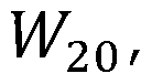 used to record an image can thus be determined by identifying the matching l^o f°r use i-n the image recovery that produces no displacement between the recovered images corresponding to Ψ and ψ * . In these circumstances, recovered images will also be
SUBSTITUTE SHEET RULE 26
free of phase-error artefacts. Thus, the recovered images will be high quality images.
More generally, we can write H^oC^^) to indicate that image defocus varies according to the range of scene components and this leads to a spatially varying shift p ^,T ^ in the recovered images. Estimation of Ρ(.ζιΉ*) , for example based on a map of the disparity (as used to characterize stereopsis for example) between the images recorded with the phase masks ^ and enables determination of a spatially varying
 the image recovery that enables recovery of an artefact-free image.
Furthermore, W^oC^^) yields an estimate of the depth map of the scene
 are the images recovered, using the deconvolving point-spread functions corresponding to P+ and P , with uniform (constant) defocus
 assumed in the recovery process and actual image defocus ' the spatial-shifting properties of the recovery process lead to a disparity between the recovered images such that,
 where ρ(ζ,η) is the scalar value describing a spatially variant displacement of scene components in the = Ή direction according to the mismatch between W^o anc^ ■
The effect of a spatially variant displacement of the recovered scene is illustrated for a simulated image of a spoke target in FIG. 2, for which H^oC^^) spatially varies with segment from zero to three waves as the orientations of the segment spokes varies from zero through 2π clockwise . Arrows

indicating disparities m are
SUBSTITUTE SHEET RULE 26
superimposed on the recovered images. In more detail, FIG. 2(a)
w20=o,w20
shows a disparity map for a recovered image T_^_ relative to a correct image of the scene superimposed on the recovered
W20=0,W2o . . .
image 7_j_ . The disparity is negative (arrows pointing from upper-right to lower-left corner) . Similarly, FIG. 2 (b) shows a corresponding disparity map for a recovered image
γ·^2ο 0,W2o reiative to a correct image of the scene superimposed on the recovered image _ ^u £U. The disparity is positive (arrows pointing from lower-left to upper-right corner). FIG.
2(c) shows the resultant disparity between the two recovered images (i.e. the difference in the previous two disparity maps) superimposed on the conventional image.
In addition to the translation shifts, phase-mismatch artefacts caused by mismatches between W20 and I/20 are apparent in the recovered images. In consequence, Equation (2) may not strictly hold. Nevertheless, calculation of the disparity map, 2?(^,77) , is possible since the translation shift is by far the dominant effect. Conversely, for spatially

variant deconvolution with
vanishes and therefore phase-artefacts are not present in
Equation (2). The recovered image is then artefact-free.
Rather than calculating the disparity map which results from the recovery using uniform I/2O' in this embodiment it is considered more convenient to seek the spatially-variant

f°r use -"-n ima9e recovery that produces a null disparity map between the recovered images, since the artefacts will be suppressed as the solution is approached. Of course, in other embodiments of the present invention the defocus may instead be determined by calculating the disparity map (or more generally by determining translations between the
SUBSTITUTE SHEET RULE 26
recovered images) and determining the defocus based on the disparity map (or based on the determined translations) .
In other words, in this embodiment we calculate
VI/20^">^?) f°r use ^η the image recovery that minimizes the difference (subtraction) between the recovered images
^^" "(ξ, ) and r_ 20,W2o (^77)
' + ^77 . calculation of W20 can be performed on a per-pixel basis but, to improve
robustness, in this embodiment evaluation in a small
neighbourhood of each pixel is used in order to reduce
sensitivity to noise. We perform this neighbourhood evaluation using a smoothed representation of the difference image:
 where Ga is a Gaussian low-pass filter and its standard deviation, (7, is a compromise between noise robustness and the size of the response function that tends to segment the image according to 20(ξ,η . When £0(ξ,η~) = W20(.ξ, V > >
W20>W2o _ rW20,W2o and each recovered image will be artefact- free. If O is large, evaluation of Equation (3) becomes less sensitive to noise and to scene features, but at the expense of lower lateral resolution for detection of spatial changes in defocus; for example, for discriminating between one object in front of another.
We reconstruct the deconvolved image by Wiener filtering based on the spatially varying point-spread function

corresponding to the values of that minimize the metric in Equation (3) . We denote this recovered image by ze σ is

used and to highlight the field de endence on both the imaging

and recovery kernels, respectively.
SUBSTITUTE SHEET RULE 26
In practice, this reconstruction strategy may result in local changes in contrast, which may manifest as slightly brighter or darker patches in the recovered image. This effect may be removed in embodiments of the present invention by averaging the images obtained for a range of values of (7. These changes in image contrast are quite abrupt and hence introduce non-physical frequency components beyond the optical cut-off frequency. Such frequency components may be attenuated in embodiments of the present invention by using a low-pass filter, with negligible effect on the image quality. The final
reconstructed image produced in embodiments of the present invention may thus be written as :

where for clarity the ζ,] dependence of 7~_|_ and T_ has been suppressed but is implicit, ^(-,Vc) is an ideal low-pass filter, and Vc is the optical cut-off frequency. Note that
reconstruction in E uation 4 follows from the set of images calculated using

Equation (3) for a range of n different (7j values.
Simulation results obtained from the application of this algorithm for the recovery of simulated images are shown in FIG. 3. A reference diffraction-limited image is shown in FIG. 3(a) and blurring by uniform defocus l^o ~ 4 is shown in FIG. 3(b) . The image in FIG. 3(c) is obtained by conventional image recovery with — 0 as typically employed for Wavefront Coding, whilst the image in FIG. 3(d) was recovered using the CKM method of embodiments of the present invention. Detected images included zero-mean, white Gaussian noise with 46dB signal-to- noise ratio. The variation with l^o °f the
SUBSTITUTE SHEET RULE 26
argument of the argmin function in Equation (3) is depicted in FIG. 3(e), where the minimum indicates the correct detected defocus K20 = ~ 4. It is apparent from these images that the CKM algorithm of an embodiment of the present invention has enabled recovery of a high-quality image free of the phase- modulation artefacts evident in FIG. 3(c) that are generally observed in Wavefront Coding. Similar results have been robustly obtained for a range of scene types and noise levels.
The ability of the CKM technique of an embodiment of the present invention to recover images with varying defocus across the field-of-view is illustrated with FIG. 4. Conventional in- focus images of a spoke target and fishing boat are shown in column (a) , simulations of the effects of spatially varying defocus H^o C^ ^) f°r conventional imaging are shown in column
(b) where W^o C^' ^) varies with orientation of the spokes for the spoke target (as for FIG. 2) and varies linearly with elevation from positive to negative defocus for the fishing boat; conventional Wavefront Coding image recovery of images recorded with a cubic phase mask and l^o — 0 is shown in column (c) and with CKM recovery according to an embodiment of the present invention in column (d) . The presence of artefacts for conventional Wavefront Coding image recovery (see FIG.
3(c)) and their absence in the CKM technique (see FIG. 3(d)) is clearly evident. Furthermore the CKM algorithm may also yield a defocus map and hence also a range map. Although the raw

defocus map n°isy where regions without texture give rise to ambiguity, restored images are
nevertheless free of phase-induced artefacts.
The two images corresponding to ψ and ψ* in embodiments of the present invention may be recorded time-sequentially, for example by rotating a phase mask through an angle of 71 , or alternatively in a snapshot by using one of the configurations shown in FIG. 5. In FIG. 5(a) a first phase mask PM1 and its
SUBSTITUTE SHEET RULE 26
conjugate PM2 are implemented in two distinct optical paths formed by splitting incident light from the scene 0 with a beam splitter BS . A collimating lens CL is positioned before the beam splitter BS . Separate detectors IP1 and IPO are used to form each of the first and second linages, and lenses Li and L.2 are used to focus the light for the first and second images onto the detectors IF1 and IPO, In FIG, 5(b) a minor
modification to FIG, 5(a) involving mirrors M enables a single detector array IP to be used to capture both the first and second images of the scene. It should be noted that CKM as described in this embodiment is unaffected by discrepancies between the two phase masks or the optics in each path and hence no matching is required. In FIG, 5 (c) , ψ and ΐμ* phase functions are implemented, as the positive and negative first diffraction orders of a dislocated diffraction grating similar to the scheme previously reported by Blanchard and Greenaway [?. M . Blanchard and A. H. Greenaway, "Simultaneous multiplane imaging with a distorted diffraction grating," Appl, Opt. 38, 6632-6699 (1999)].
If a binary diffraction grating is constructed by
alternative strips separated by a regular distance, then an incident light beam is separated into several diffracted beams that emerge at an angle from the plane of the grating, and each diffracted beam emerges at an angle proportional to the diffraction order in-0, + I , -1 , -s-2, -2, etc. The grating can be implemented with regular strips of different transmissivity, reflectivity or optical thickness. If the grating is placed at the aperture of an optical system, and local variations of the separation distance between strips are applied, then the strips will show distortion that varies across the aperture and the local variation in this separation will induce a local phase shift in the emerging beams that will be proportional to the separation and to the diffraction order. Thus by
controlling the distortion, hence the variations in local separation of strips, it is possible to introduce varying
phase shift across the aperture that corresponds to the desired phase modulation. Furthermore, since this phase shift is proportional to the diffraction order, then by considering the +1 and -1 diffraction orders, that is, the first two diffracted beams that deviate from the zero order, non- deviated and unmodulated beam, will have complex conjugate modulations. This means that applying, for example, local variations in distortion such that the phase modulation is a cubic function, then the +1 and -1 diffraction orders encode the ψ and ψ * phase functions.
FIG. 6 shows an optical configuration according to an embodiment of the present invention comprises a source OP, a lens L, a phase mask PM, a beam splitter BS, a mirror M and an image plane IP. In the optical configuration shown in FIG. 6, the method of the present invention can be implemented using a. single phase mask or a single modulation for both images, but using a different, fixed amount of defocus between the two images. This can be useful if the translation of the images is not a linear function of defocus. For example, a cubic phase mask generates translation which is a quadratic function of defocus, hence a cubic phase modulation with two different defocuses are valid dissimilar modulations for the two images. The two defocuses are readily implemented by different imaging paths leng hs; hence it can be practically implemented using a single physical phase modulation optical component. However, in other embodiments the different fixed amount of defocus between the two images can be implemented in a different way. Therefore, in this embodiment the first, and second modulations comprise a common phase modulation (a cubic phase modulation) and dissimilar defocuses.
In the experimental setup described in the following a time-sequential implementation of ψ and ψ* was instead achieved using a Spatial Light Modulator, which provides a greater convenience of calibration.
Experimental Setup
In an experimental setup the CKM technique of an
embodiment of the present invention was demonstrated using a conventional finite-conjugate imaging configuration employing a spatial-light modulator (SLM) to time-sequentially implement the phase functions ψ and ψ* and indeed the more general phase functions P+ and P~ that include defocus, l^o · A mechanical time-sequential implementation is also possible: for example by rotation of a refractive cubic-phase mask through 7 radians about the optic axis to switch between ψ and Iff . However, practical implementation can possibly introduce errors into the measurement of P associated with uncertainties in the deviation of the images by the phase mask. Furthermore, accurate calibration of the variation of β and point-spread function with l^o based on defocus of the system point-spread function can be more readily achieved with an SLM than by mechanical defocus of, for example, a pinhole. Of course, snapshot implementations in which the two images are captured simultaneously, such as those illustrated in FIG. 5, are also possible.
The experimental setup is shown in FIG. 7 and comprises an imaging lens L, light source LS, tilted slide TS, spatial light modulator SLM and detector I. Using object and image distances of 350mm and 1650mm, an f/15 singlet imaging lens L of focal length 300mm forms an in-focus image I with a nominal magnification of approximately five on a Hamamatsu Orca CCD detector. A polarizer, quarter-wave plate and analyzer are used with the SLM yielding a maximum phase modulation of 3π 12 with total amplitude modulation <4% using illumination at a wavelength of 543nm. An iris placed adjacent to the SLM ensures that the SLM is in the aperture stop of the system so that phase coding is independent of field angle.
SUBSTITUTE SHEET RULE 26
As described below, the CKM method of an embodiment of the present invention is demonstrated for imaging of three- dimensional test targets involving significant defocus .
Calibration of the variation of point spread function
intensity distribution and displacements P with l^o
required for accurate image recovery and estimation of
 was achieved by recording the image of a Ιμιη pinhole located in the object plane of the imaging system.
Two hundred point-spread functions were recorded for pupil functions P+ and P~ implemented with the SLM, that is, for encoding functions for ψ and , and for defocus varying equidistantly in the range —3 ^ W20 — ^ · T^e variations of
P with K20 as determined by correlation of each point- spread function with the reference (in-focus) point-spread function for P and P together with least-square fits of quadratic functions are shown in FIG. 8. The quadratic fits were used to improve the estimate of the noise-free point- spread function position that was subsequently used in image recovery .
The best-fit quadratic functions correspond to an that is approximately 21% greater for P than for P .
Measurement with a Shack-Hartman sensor of the phase fronts produced by the SLM yields best-fit cubic wavefronts for P and P that correspond to values of a comparable to this measured asymmetry. Although this asymmetry could be removed by a pixel-wise calibration of the SLM phase function, this illustration demonstrates that the technique is robust to such aberrations .
Experimental Results - Artefact Removal
As an example application of the technique of the present invention we present the application of a CKM technique
SUBSTITUTE SHEET RULE 26
according to an embodiment of the present invention to imaging of microscope slides. Shown in FIG. 9 is an image of a section of the petiole of a leaf and in FIG. 10 a sample of seeds and a pine-leaf section. To provide appreciable range of defocus the object in FIG. 9(a) was tilted to provide a linear variation in defocus in the vertical direction and the two samples in FIG. 10(a) were separated by a glass slide of constant thickness. In each case the defocus is l^o ¾ 1-6.
FIG. 9(b) and FIG. 10(b) show the corresponding images captured by means of a Wavefront Coding system with l^o = 0 in the image recovery, where the out-of-focus regions of the scene exhibit clear phase-error artefacts . For the images captured and reconstructed with a CKM system according to an embodiment of the present invention shown in FIG. 9(c) and FIG. 10(c), however, the artifacts are effectively eliminated, which in turn enables image details to be more readily
discerned. In addition, FIG. 10(d) shows the image recovered using a commercial focus-stack algorithm (Helicon focus V5.3 ) generated using 201 images taken over a defocus range of
—3 - 3 at steps of 0.03 waves. Comparing FIG. 10(c) and FIG. 10(d), one can observe that using just two recorded images the CKM technique demonstrates comparable image quality to that obtained with the 201-image focus-stack algorithm.
The line plots shown in FIG. 10(e) correspond to a mid- height intensity horizontal profile taken along the dashed lines shown in FIG. 10(b), (c) and (d) . Whilst strong
artefactual oscillations are evident on the traditional
Wavefront Coding profile, these are absent in the CKM images. The commercial focus-stack reconstruction algorithm employs some form of smoothing which we do not use in the CKM recovery as can be observed by comparing FIG. 10(d) to FIG. 10(c) . This explains why some peaks are shallower than the corresponding peaks in the CKM recovery.
SUBSTITUTE SHEET RULE 26
Experimental Results - Depth Estimation
As stated above, the CKM technique of the present invention may evaluate the defocus in a small region of an image, so that it is possible to reconstruct a scene in 3D provided sufficient texture is present. The use of CKM image reconstruction for three-dimensional ranging was assessed by imaging a calibration target consisting of a regular array of disks tilted at an angle of roughly 65° with respect to the nominal image plane, introducing defocus of 0.3 < W20≤ 2.0.
Images of the calibration target captured with a conventional imaging system, Wavefront Coding system and a CKM system according to an embodiment of the present invention are shown in FIG. 11(a), FIG. 11(b) and FIG. 11(c) respectively.
Reconstruction of the three-dimensional defocus map involved averaging over the region of each disk; that is, avoiding the textureless areas that do not provide defocus information. The calibration target was aligned such that there is effectively uniform defocus along each row of disks and a linear variation in defocus along each column. A ground truth slope was calculated by centroiding several disks and taking the ratio between their average horizontal to vertical separation. This was found to be 1.976 + 0.002, which is approximately tan(65°) as expected.
Measurements of the range of each disk using the snapshot CKM measurement of defocus and based on a time-sequentially recorded focus-stack were performed. For the focus-stack measurement an image-sharpness criterion was used to select the plane of best focus as the SLM was used to vary the focus of the image in steps of 0.03 waves. The range of each disk as computed by both the CKM and the focus-stack are shown plotted in FIG. 12(b) . Additionally, for illustration purposes, a three-dimensional reconstruction of the
calibration target as computed by the CKM method is shown in FIG. 12(a) .
SUBSTITUTE SHEET RULE 26
The gradients of the least-square linear fits is 2.00 + 0.01 for the CKM technique and 1.95 ± 0.02 for the focus-stack measurement. This means the CKM measurement is 1.21% greater than the ground truth whilst the focus-stack measurement is 1.31% smaller. These results suggest that CKM can potentially equal or exceed the ranging accuracy of focus-stacking. The uncertainty in range for the CKM technique is 40μιη which corresponds to a l^o °f 0.036 waves of defocus (16% larger than the quantization step) and to 1.84% of the depth range.
It can therefore be concluded that the CKM technique according to an embodiment of the present invention can be employed to capture three-dimensional range-resolved images with extended depth of field using just two data acquisitions and, in principle, in a single snapshot using one of the techniques shown in FIG. 5, for example. The present
invention is therefore expected to be relevant for a wide range of time-resolved imaging applications, including extended depth of field microscopy or particle image
velocimetry, as well as other applications.
In summary, the present inventors have achieved the first demonstration of artefact-free, extended depth of field imaging with simultaneous ranging using hybrid-imaging techniques . In previously reported approaches to hybrid imaging a range of phase functions have been reported that tend to fall into two classes : either the antisymmetric cubic and trefoil masks (or qualitatively similar shapes) or symmetric masks, and these provide complementary advantages. While the former offers a superior trade-off between enhanced depth of field and noise amplification, the spatial-phase effects introduced by the asymmetry introduce highly
problematic artifacts and also range-dependent image shifts that may be absent for symmetric phase functions . The present inventors have demonstrated that by recording images with complementary optical transfer function characteristics it may be possible to benefit from the enhanced depth of field of an
SUBSTITUTE SHEET RULE 26
antisymmetric mask, but without introducing image artefacts, and combined with the enhancement of three-dimensional ranging. This so-called complementary-kernel imaging
constitutes a new paradigm, for hybrid imaging that builds on the early use of multiple kernels by Kausler .
The proposed method has been verified both by simulation and by experiment. Simulation results show suppression of restoration artefacts even at relatively low signal-to-noise ratios. Experimental results show that high-quality,,
artefact-free images can be obtained even for large defocus . In addition, CKM provides a means of 3D image reconstruction and, following proper calibration., range measurement .
Experimental results relating to an embodiment of the present invention are now described. In this embodiment the present invention is implemented on a microscope. In this embodiment a single phase modulation of the incident beam is employed and the first and second images are recorded by using two different values of defocus (in other words the same general concept as the embodiment illustrated in FIG. 6 and described above) ,
The specific experimental setup used is shown in FIG, 13, in which 0 is the object being imaged, Obj is the objective, PP is the pupil plane, TL is a tube lens, IP1 is an
intermediate imaging plane, LI is a first, lens, LP is a linear polarizer, SLM is a spatial light modulator, L2 is a second lens and I is the image.
The optical pupil of the microscope objective is re- imaged onto a plane, where a Spatial Light Modulator is placed, and implements the desired phase modulation, The microscope is an inverted microscope and the objective lens is moved relative to the sample to generate different defocus . In this case the objective was a 20x with NA-0.5 and. -with a depth-of- field of approximately 3 microns,
In this embodiment the incident bea is modulated using phase modulation and a cubic phase modulation is implemented,
The first image is generated applying this common cubic phase modulation plus a certain amount of defocus, and the second image is generated applying the common cubic phase modulation plus a different amount of defocus .
Furthermore this implementation selects the second amoun of defocus to be equal to the first amount of defocus but of differen sign. To implement this configuration the SLM encoded the common cubic phase modulation,, and the first and second images are captured time sequentially by moving the microscope objective a given distance. It can be seen how this configuration produces a disparity between the first image and the second image that is linearly proportional to the difference in defocus of the two images, and linearly proportional to the actual defocus in the scene.
This configuration provides two advantageous properties: the sensitivity of the system for distinguishing defocus in the scene, that is the difference in translation in first, and second images of the image components per wave of defocus present in the scene, is constant regardless of the defocus in the scene and can be controlled through the defocus difference between first and second images of the scene.
Example results obtained using this experimental setup are shown in FIG . 14. Shown in FIGS. 14(a) to (d) are images of a sample of mustard seeds roughly 40um thick. FIG. 14{a) is a diffraction limited image. FIG. 14 (b) is an image produced using conventional hybrid imaging. FIG. 1 (c} is an image produced using the present invention. FIG, 14(d) is an image produced using focus-stack reconstruction. FIG. 14 (e) is a 3D reconstruction of a tilted dot target, with lOum dot spacing .
By comparing FIG. 14(b) to FIG. 14(c), one can appreciate the improvement in image quality obtained through the
technique of the present invention over conventional hybrid imaging. A focus-stack was also performed by taking
approximately 200 images along the depth of the sample and the
result is shown in FIG. 14(d) . Comparing this to FIG. 14 (c) , one can say that, in a single snapshot, the method of the present invention gives results comparable to what focus- stacking yields from 200 images. Finally, the 3D
reconstruction of a tilted, dot-distortion target is shown in FIG. 14(e) for demonstration purposes. In this case, the total depth induced by the tilt was about. 35μτη..
Further experiment l results relating to an embodiment o the present invention are now described. In this embodiment a single phase modulation of the incident beam is employed and the first and second images are recorded by using two
different values of defocus. The layout of the experimental system was the same as shown in FIG. 6
The lens used in FIG. 6) is a 5Oram focal length
Nikon Nikkor(TM) AF SLR, which was modified to accommodate a glass phase mask { *PM' in FIG . 6) in its aperture stop that implements a cubic phase modulation of approximately =12λ across the pupil of the lens. &z , as shown in FIG, 6, was approximatel 95mm, and this produced a translation of the scene components in the image plane that was measured to be of 5.58 pixels per wave of defocus, employing a camera (Andor
Zyla(TH) 5.5) with a pixel pitch of 6,5 microns. Results following this im 1ement tion are shown in FIGS. 15 to 18, discussed below.
FIG. 15 shows the difference in translation between first and second images of the scene components in the image plane as a function of the defocus of the scene.
In one experiment, a grid distortion target was tilted and. imaged. FIG, 16 shows its reconstructed depth obtained using the present invention and FIG. 17 shows the determined depth averaged along the x-direction.
FIG. 18 shows a reconstruction image reconstructed using the present invention of a microscope sample with a step change in defocus across the fie.ld-of--v.iew (i.e. different regions of the scene have a different amounts of defocus ,
differing in approximately four waves), demonstrating the extension in depth-of-field that can be achieved with, the present invention.
Numerous other practical setups can be used to implement the present invention. For example, an alternative
experimental setup may integrate the present invention into a microscope by providing a refractive glass phase mask and using one of two different configurations, either (i)
obtaining the first and second images time sequentially by- moving the objective between images, or (ii) obtaining the first and second images using a customised beam splitter to introduce different values of defocus in the different images .
Claims
1. A method of evaluating defocus in. an image of a scene com ri si g :
applying first modulation to incident light from the scene to generate a first image of the scene;
applying second modulation to incident light from the scene to generate a second image of the scene;
calculating first recovered image data fro the first image using a first recovery kernel corresponding to the first modulation and specified defocus data;
calculating second recovered image data from the second image using a second recovery kernel corresponding to the second modulation and specified defocus data;
calculating defocus data based on comparison of the firs recovered image data, and the second, recovered image data.
2. The method according to claim 1, wherein applying first modulation to incident light from the scene comprises
capturing the first image with an optical system having a first point-spread function.
3. The method according to claim 1 or claim 2, wherein applying second modulation to incident light, from, the scene comprises capturing the second image with an optical system having a second point-spread function.
4. The method according to any one of the previous claims, wherein applying first modulation to incident light from the scene comprises applying phase modulation to incident light from the scene,
5. The method according to any one of the previous claims, wherein applying second modulation to incident light, from the
scene comprises applying phase modulation to incident, light from the scene,
6. The method according to any one of the previous claims, wherein :
applying first modulation to incident light from the scene comprises applying first phase modulation to incident light from, the scene to generate the first image; and
applying second modulation to incident light from the scene comprises applying second phase modulation to incident light from the scene to generate the second image ,
7. The method according to claim 6, wherein t e second phase modulation, corresponds to the complex conjugate of the first phase modulation.
8. The method according to claim 6 or claim 7, wherein the first phase modulation is applied using a first phase mask and the second phase modulation is applied using a second phase mask »
9. The method according to any one of claims 1 to 5, wherein the method, comprises:
applying modulation to incident light from the scene to generate modulated incident light; and
generating the first and second images from the modulated incident light, wherein generating the first and second images from the modulated incident light comprises generating a different fixed amount of defocus between the first and second images ,
10. The method according to claim 9, wherein applying modulation to the incident light comprises applying phase modulation to the incident light to generate phase modulated incident light.
11, The method according to claim 9 or claim 10, wherein generating the different fixed amount of defocus between the first and second images comprises generating the first and second images with different imaging path lengths.
12, The method according to claim 10, wherein the phase modulation is applied using a phase mask,
13, The method according to any one of claims 1 to 5, wherein the method comprises:
applying modulation to incident light from, the scene, to generate modulated incident light; and
generating the first and second images from, the modulated incident light, wherein generating the first and second images from the modulated incident light comprises generating chromatic aberration in the modulated incident light and subsequently capturing the first and second images from different colour components of the modulated incident light.
14, The method according to claim 13, wherein the first and second, images are captured using the same colour image sensor,
15, The m.eth.od. according to any one of the previous claims, wherein the first modulation or the second modulation
comprises :
a generalised cubic phase modulation;
an asymmetric tangent phase modulation;
a logarithmic phase modulation;
an asymmetric monomial phase modul tion;
an asymmetric fractional-power phase modulation;
an asymmetric, exponential phase modulation;
a polynomial phase modulation;
a free-form phase modulation;
a sinusoidal phase modulation;
a quartic phase modulation; or
a logarithmic asp ere phase modulation.
16. The method according to any one of the previous claims, wherein the first modulation or the second modulation
comprises an anti-symme rie modulation.
17. The method according to any one of the previous claims, wherein one or both of the first and second modulations responds asymmetrically with defocus.
IS. The method according to any one of the previous claims, wherein calculating defocus data comprises calculating defocus data based on information indicative of translation (s } between the first and second recovered, image data.
19. The method according to any one of the previous claims, wherein calculating defocus data comprises determining a defocus amount for each of a plurality of regions of the first or second image.
20. The method according to claim 19, wherein each of the plurality of regions is a single pixel.
21. The method according to claim 19, wherein each of the plurality of regions is a plurality of pixels.
22. The method according to any one of the previous claims, wherein calculating defocus data comprises determining specified defocus data for use in calculating the first and second recovered image data that results in. the first, and second recovered image data being substantially the same.
23. The method according to any one of the previous claims, wherein calculating defocus data comprises calculating
specified defocus data for use in calculating the first
recovered image data and the second recovered image data that minimises a metric that represents a difference between the first recovered image data and the second recovered image data.
24. The method according to claim 23, wherein determining the defocus data comprises determining, for each of a plurality of regions of the first or second image, a defocus amount that minimises the metric for the region.
25. The method according to claim 24, wherein the metric for the region represents a difference between first recovered image data recovered from that region of the first image and second recovered image data recovered from that region of the second image .
26. The method according to any one of claims 23 to 25, wherein the metric represents subtraction of the first recovered image data and the second recovered image data.
27. The method according to any one of claims 23 to 26, wherein the metric represents a smoothed representation of the
difference between the first recovered image data and the second recovered image data.
28. The method according to any one of claims 23 to 27, wherein the metric is :
W20(ξ>η = arg

29. The method according to any one of claims 1 to 22, wherein calculating defocus data comprises calculating specified defocus data for use in calculating the first recovered image data and the second recovered image data that minimises a metric that represents optical flow between the first recovered image data and the second recovered image data .
30. The method according to any one of claims 1 to 22, wherein the first recovered image data and the second
recovered image data are each calculated by solving a forward model of the system = Mi, where the vector i is the lexicographically ordered captured image, the vector is the lexicographically ordered recovered image and M is a matrix that relates the two through the point-spread function at each region .
31. The method according to claim 30, wherein calculating defocus data comprises determining defocus values for use in calculating the matrices M]_ and M∑ for the first and second images i]_ and i∑ such that Μύ.]_ = ΜΣΪΣ-
32. The method according to any one of claims 1 to 21, wherein calculating defocus data comprises calculating defocus data by calculating, for each of a plurality of regions of the first or second image, a defocus amount for the region based on a translation of the region between the first recovered image data and the second recovered image data.
33. The method according to claim 32, wherein the method comprises determining the translation of the region between the first recovered image data and. the second recovered image data based on registration of the first recovered image data and the second recovered image data.
34. The method according to claim 33, wherein the
registration is based on:
registration of pixel intensities; or
registration of image features.
35. The method according to claim 32, wherein the method comprises determining rhe translation of the region between the first recovered image data and the second recovered image data based on an optical flow between the first recovered image data and the second recovered image data.,
36. The method according to any one of claims 32 to 35, wherein the specified defocus data used in calculating the first recovered image data and the specified, defocus data used in calculating the second recovered image data comprise the same uniform defocus.
37. The method according to any one of claims 1 to 35, wherein the specified defocus data used in calculating the first recovered image data and the specified defocus data used in calculating the second recovered image data comprise the same defocus data.
38. A method of producing an image of a scene comprising: determining defocus data by the method of any one of the previous claims ;
calculating a recovered image from the first image using a recovery kernel corresponding to the first modulation and the calculated defocus data,
corresponding to a range of n different standard

deviations CTj d W 20 is the actual defocus data.
39. The method according to claim 38, wherein the method comprises calculating a recovered image from the second image using a recovery kernel corresponding to the second modulation and the calculated defocus data.
40. The method according to claim 38 or claim 39, wherein the method comprises:
determining a plurality of sets of defocus data by the method of claim 27 or claim 28, wherein each of the plurality of sets of defocus data is obtained based on a smoothed
representation produced with a smoothing function having a different standard deviation;
calculating a plurality of recovered images based on the plurality of sets of defocus data; and
averaging the plurality of images.
41. The method according to claim 40, wherein the method further comprises applying a low-pass filter to the result of the averaging .
42. The method according to claim 41, wherein the image is produced by the following equation:

correspond to recovered images respectively calculated from the first and second images based on n determined defocus data
57
43. The method according to any one of the previous claims, wherein the first and second images are acquired time
sequentially .
44. The method according to any one of claims 1 to 42, wherein the first and second images are acquired
simultaneously .
45. An apparatus for evaluating defocus in an image of a scene, the apparatus comprising:
a modulator for applying first modulation to incident light from the scene to generate a first image of the scene; a modulator for applying second modulation to incident light from the scene to generate a second image of the scene; one or more detectors for acquiring the first image of the scene and the second image of the scene; and
processing means configured to control the apparatus to perform the method according to any one of the previous claims .
46. The apparatus according to claim 45, wherein the
apparatus comprises :
a beam splitter for splitting incident light from the scene into first and second light beams;
a first image plane for forming a first image from the first light beam; and
a second image plane for forming a second image from the second light beam;
wherein the first modulation is provided by a first phase modulator arranged so that the first light beam passes through the first phase modulator before the first image is formed on the first image plane; and
wherein the second modulation is provided by a second phase modulator arranged so that the second light beam passes through the second phase modulator before the second image is formed on the second image plane.
47. The apparatus according to claim -15, wherein the
apparatus comprises :
a beam splitter for splitting incident light from the scene into first and second light beams; and
an image plane for forming first and second images fro the first, and second light beams ;
wherein the first modulation is provided by a first phase modulator arranged so that the first light beam passes through the first phase modulator before forming a first image at a first position on the image plane; and
wherein the second modulation is provided by a second phase modulator arranged so that the second light beam passes through the second phase modulator before forming a second image at a second position on the image plane.
48. The apparatus according to claim 45, wherein:
the apparatus comprises a distorted diffraction grating configured to apply different phase modulations to different diffraction orders of diffracted light;
the first image is generated from light from one of the diffraction orders of the diffracted light; and
the second image is generated from light from; another of the diffraction orders of the diffracted light.
49. The apparatus according to claim 48, wherein:
the first image is generated from light from the +1 diffraction order of the diffracted light; and
the second image is generated from light from the -1 diffraction order of the diffracted light.
50. The apparatus according to claim 45, wherein the apparatus comprises :
a phase modulator for applying phase modulation to incident light from the scene to generate phase modulated incident light;
a first, optical path configured to direct the phase raoduiated incident light to an image plane to form the first image; and
a second optical path configured to direct the phase modulated incident light to an. image plane to form the second image;
wherein the first optical path and. the second optical path have different optical path lengths.
51. Ά method of evaluating defocus in an image of at scene substantially according to any one embodiment herein described with reference to the accompanying figures,
52. An apparatus for evaluating defocus in an image of a scene substantially according to any one embodiment herein described wit reference to, and as illustrated in, figures 2 to 12.
Applications Claiming Priority (2)
| Application Number | Priority Date | Filing Date | Title |
|---|---|---|---|
| GBGB1410631.4A GB201410631D0 (en) | 2014-06-13 | 2014-06-13 | Method and apparatus for evaluating defocus in an image of a scene |
| GB1410631.4 | 2014-06-13 |
Publications (1)
| Publication Number | Publication Date |
|---|---|
| WO2015189642A1 true WO2015189642A1 (en) | 2015-12-17 |
Family
ID=51266604
Family Applications (1)
| Application Number | Title | Priority Date | Filing Date |
|---|---|---|---|
| PCT/GB2015/051743 Ceased WO2015189642A1 (en) | 2014-06-13 | 2015-06-12 | Method and apparatus for evaluating defocus in an image of a scene |
Country Status (2)
| Country | Link |
|---|---|
| GB (1) | GB201410631D0 (en) |
| WO (1) | WO2015189642A1 (en) |
Cited By (2)
| Publication number | Priority date | Publication date | Assignee | Title |
|---|---|---|---|---|
| CN111191550A (en) * | 2019-12-23 | 2020-05-22 | 初建刚 | Visual perception device and method based on automatic dynamic adjustment of image sharpness |
| CN116243471A (en) * | 2023-04-06 | 2023-06-09 | 苏州芯之光科技有限公司 | Depth of Field Restoration Device, Method, Equipment and Medium Based on Spatial Light Modulator |
Citations (1)
| Publication number | Priority date | Publication date | Assignee | Title |
|---|---|---|---|---|
| US20100008597A1 (en) * | 2006-11-21 | 2010-01-14 | Stmicroelectronics (Research & Development) Limited | Artifact removal from phase encoded images |
-
2014
- 2014-06-13 GB GBGB1410631.4A patent/GB201410631D0/en not_active Ceased
-
2015
- 2015-06-12 WO PCT/GB2015/051743 patent/WO2015189642A1/en not_active Ceased
Patent Citations (1)
| Publication number | Priority date | Publication date | Assignee | Title |
|---|---|---|---|---|
| US20100008597A1 (en) * | 2006-11-21 | 2010-01-14 | Stmicroelectronics (Research & Development) Limited | Artifact removal from phase encoded images |
Non-Patent Citations (5)
| Title |
|---|
| MADS DEMENIKOV; ANDREW R. HARVEY: "Parametric blind-deconvolution algorithm to remove image artifacts in hybrid imaging systems", OPTICS EXPRESS, vol. 18, no. 17, 16 August 2010 (2010-08-16), pages 18035, XP055212196, DOI: 10.1364/OE.18.018035 * |
| MURALI SUBBARAO ET AL: "FOCUSED IMAGE RECOVERY FROM TWO DEFOCUSED IMAGES RECORDED WITH DIFFERRENT CAMERA SETTINGS", IEEE TRANSACTIONS ON IMAGE PROCESSING, IEEE SERVICE CENTER, PISCATAWAY, NJ, US, vol. 4, no. 12, 1 December 1995 (1995-12-01), pages 1613 - 1627, XP000542081, ISSN: 1057-7149, DOI: 10.1109/83.475512 * |
| PAUL ZAMMIT ET AL: "Extended depth-of-field imaging and ranging in a snapshot", OPTICA APPLICATA, OFICYNA WYDAWNICZA POLITECHNIKI WROCLAWSKIEJ, PL, vol. 4, no. 1, 26 September 2014 (2014-09-26), pages 209 - 216, XP009185992, ISSN: 0078-5466 * |
| SEAN QUIRIN AND RAFAEL PIESTUN: "Depth estimation and image recovery using broadband, incoherent illumination with engineered point spread functions [Invited]", APPLIED OPTICS, OPTICAL SOCIETY OF AMERICA, WASHINGTON, DC; US, vol. 52, no. 1, 1 January 2013 (2013-01-01), pages A367 - A376, XP001580242, ISSN: 0003-6935, DOI: HTTP://DX.DOI.ORG/10.1364/AO.52.00A367 * |
| V. GORELIK: "Two-kernel image deconvolution", OPTICS EXPRESS, VOL. 16, NO. 7, PP. 4479-4486 (2008), vol. 21, no. 22, 4 November 2013 (2013-11-04), pages 27269, XP055213703, ISSN: 2161-2072, DOI: 10.1364/OE.21.027269 * |
Cited By (2)
| Publication number | Priority date | Publication date | Assignee | Title |
|---|---|---|---|---|
| CN111191550A (en) * | 2019-12-23 | 2020-05-22 | 初建刚 | Visual perception device and method based on automatic dynamic adjustment of image sharpness |
| CN116243471A (en) * | 2023-04-06 | 2023-06-09 | 苏州芯之光科技有限公司 | Depth of Field Restoration Device, Method, Equipment and Medium Based on Spatial Light Modulator |
Also Published As
| Publication number | Publication date |
|---|---|
| GB201410631D0 (en) | 2014-07-30 |
Similar Documents
| Publication | Publication Date | Title |
|---|---|---|
| Zammit et al. | Extended depth-of-field imaging and ranging in a snapshot | |
| US7646549B2 (en) | Imaging system and method for providing extended depth of focus, range extraction and super resolved imaging | |
| CN103826033B (en) | Image processing method, image processing equipment, image pick up equipment and storage medium | |
| CN115546285B (en) | Large-depth-of-field stripe projection three-dimensional measurement method based on point spread function calculation | |
| US7260251B2 (en) | Systems and methods for minimizing aberrating effects in imaging systems | |
| EP2487522B1 (en) | Apparatus for three-dimensional image capture with extended depth of field | |
| US8432479B2 (en) | Range measurement using a zoom camera | |
| US10628927B2 (en) | Rapid image correction method for a simplified adaptive optical system | |
| US7961969B2 (en) | Artifact removal from phase encoded images | |
| US20180122092A1 (en) | Apparatus and Method for Capturing Images using Lighting from Different Lighting Angles | |
| WO2010016625A1 (en) | Image photographing device, distance computing method for the device, and focused image acquiring method | |
| US20100008597A1 (en) | Artifact removal from phase encoded images | |
| US11347133B2 (en) | Image capturing apparatus, image processing apparatus, control method, and storage medium | |
| CN107209061B (en) | Method for determining complex amplitudes of scene-dependent electromagnetic fields | |
| WO2015189642A1 (en) | Method and apparatus for evaluating defocus in an image of a scene | |
| Matsui et al. | Half-sweep imaging for depth from defocus | |
| WO2013124664A1 (en) | A method and apparatus for imaging through a time-varying inhomogeneous medium | |
| Luo et al. | Depth from Coupled Optical Differentiation: J. Luo et al. | |
| ZAMMIT et al. | Extended depth-of-field imaging and ranging in | |
| NL2001777C2 (en) | Sharp image reconstructing method for use in e.g. digital imaging, involves reconstructing final in-focus image by non-iterative algorithm based on combinations of spatial spectra and optical transfer functions | |
| Pathak et al. | A zonal wavefront sensor with multiple detector planes | |
| JP2018088587A (en) | Image processing method and image processing apparatus | |
| Spinoulas et al. | Performance comparison of ultra-miniature diffraction gratings with lenses and zone plates | |
| Zammit et al. | Three-dimensional imaging and ranging in a snapshot with an extended depth-of-field | |
| US9532032B2 (en) | Astigmatic depth from defocus imaging using intermediate images and a merit function map |
Legal Events
| Date | Code | Title | Description |
|---|---|---|---|
| 121 | Ep: the epo has been informed by wipo that ep was designated in this application |
Ref document number: 15730236 Country of ref document: EP Kind code of ref document: A1 |
|
| NENP | Non-entry into the national phase |
Ref country code: DE |
|
| 122 | Ep: pct application non-entry in european phase |
Ref document number: 15730236 Country of ref document: EP Kind code of ref document: A1 |