WO2015186263A1 - 内燃機関 - Google Patents
内燃機関 Download PDFInfo
- Publication number
- WO2015186263A1 WO2015186263A1 PCT/JP2014/066359 JP2014066359W WO2015186263A1 WO 2015186263 A1 WO2015186263 A1 WO 2015186263A1 JP 2014066359 W JP2014066359 W JP 2014066359W WO 2015186263 A1 WO2015186263 A1 WO 2015186263A1
- Authority
- WO
- WIPO (PCT)
- Prior art keywords
- exhaust
- passage
- exhaust gas
- compressors
- intake
- Prior art date
- Legal status (The legal status is an assumption and is not a legal conclusion. Google has not performed a legal analysis and makes no representation as to the accuracy of the status listed.)
- Ceased
Links
Images

Classifications
-
- F—MECHANICAL ENGINEERING; LIGHTING; HEATING; WEAPONS; BLASTING
- F02—COMBUSTION ENGINES; HOT-GAS OR COMBUSTION-PRODUCT ENGINE PLANTS
- F02B—INTERNAL-COMBUSTION PISTON ENGINES; COMBUSTION ENGINES IN GENERAL
- F02B37/00—Engines characterised by provision of pumps driven at least for part of the time by exhaust
-
- F—MECHANICAL ENGINEERING; LIGHTING; HEATING; WEAPONS; BLASTING
- F02—COMBUSTION ENGINES; HOT-GAS OR COMBUSTION-PRODUCT ENGINE PLANTS
- F02B—INTERNAL-COMBUSTION PISTON ENGINES; COMBUSTION ENGINES IN GENERAL
- F02B37/00—Engines characterised by provision of pumps driven at least for part of the time by exhaust
- F02B37/007—Engines characterised by provision of pumps driven at least for part of the time by exhaust with exhaust-driven pumps arranged in parallel, e.g. at least one pump supplying alternatively
-
- F—MECHANICAL ENGINEERING; LIGHTING; HEATING; WEAPONS; BLASTING
- F02—COMBUSTION ENGINES; HOT-GAS OR COMBUSTION-PRODUCT ENGINE PLANTS
- F02M—SUPPLYING COMBUSTION ENGINES IN GENERAL WITH COMBUSTIBLE MIXTURES OR CONSTITUENTS THEREOF
- F02M26/00—Engine-pertinent apparatus for adding exhaust gases to combustion-air, main fuel or fuel-air mixture, e.g. by exhaust gas recirculation [EGR] systems
-
- Y—GENERAL TAGGING OF NEW TECHNOLOGICAL DEVELOPMENTS; GENERAL TAGGING OF CROSS-SECTIONAL TECHNOLOGIES SPANNING OVER SEVERAL SECTIONS OF THE IPC; TECHNICAL SUBJECTS COVERED BY FORMER USPC CROSS-REFERENCE ART COLLECTIONS [XRACs] AND DIGESTS
- Y02—TECHNOLOGIES OR APPLICATIONS FOR MITIGATION OR ADAPTATION AGAINST CLIMATE CHANGE
- Y02T—CLIMATE CHANGE MITIGATION TECHNOLOGIES RELATED TO TRANSPORTATION
- Y02T10/00—Road transport of goods or passengers
- Y02T10/10—Internal combustion engine [ICE] based vehicles
- Y02T10/12—Improving ICE efficiencies
Definitions
- the present invention relates to an improvement of an internal combustion engine that performs supercharging of intake air using a compressor and exhaust gas recirculation for recirculating a part of exhaust gas to the intake air.
- a supercharger such as a turbocharger or a supercharger in order to increase output or improve fuel efficiency.
- the supercharger includes a compressor, and the intake air in the intake pipe is compressed by the compressor and supplied to the combustion chamber of the internal combustion engine.
- exhaust gas recirculation that suppresses an excessive increase in the combustion temperature of fuel by recirculating a part of the exhaust gas to the supply air to the combustion chamber for exhaust gas purification.
- JP2011-089524A issued by the Japan Patent Office in 2011 proposes to increase the supercharging efficiency by providing two compressors in parallel.
- the exhaust immediately after flowing into the intake pipe from the exhaust recirculation pipe does not immediately mix with the intake air (fresh air) in the intake pipe, and the concentration of the exhaust gas of the fresh air and the exhaust gas mixed to be supplied to the plurality of compressors are not necessarily uniform.
- the temperature of the compressor that sucks the mixed gas with a high exhaust concentration rises greatly, while the temperature rise of the compressor that sucks the mixed gas with a low exhaust concentration is suppressed to a small level.
- the exhaust gas recirculation amount must be determined so that the compressor having the largest temperature rise is not damaged, and as a result, sufficient exhaust gas recirculation may not be performed.
- an object of the present invention is to equalize the temperature rise of the compressor due to the reflux exhaust in the internal combustion engine including a plurality of supercharging compressors and the exhaust gas recirculation device.
- an internal combustion engine includes a plurality of compressors that supercharge a mixed gas in an intake passage, and a part of exhaust gas flows into fresh air upstream of the plurality of compressors. And an exhaust gas recirculation passage for generating a mixed gas in the intake passage.
- the exhaust gas recirculation passage includes exhaust gas recirculation branch passages that branch into the same number or more as the plurality of compressors.
- the exhaust gas recirculation branch passage is individually connected to an intake passage upstream of the plurality of compressors.
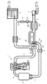
- FIG. 1 is a schematic configuration diagram of an internal combustion engine according to a first embodiment of the present invention.
- FIG. 2 is a schematic configuration diagram of an internal combustion engine according to a second embodiment of the present invention.
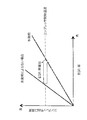
- FIG. 3 is a diagram comparing the exhaust gas recirculation (EGR) rates of the internal combustion engine according to the first embodiment of the present invention and the internal combustion engine not according to the present invention.
- EGR exhaust gas recirculation
- the multi-cylinder internal combustion engine 1 mixes the intake air sucked from the intake passage 2 with fuel and burns it, and generates rotational force by the combustion energy. Combustion gas generated as a result of combustion is discharged via the exhaust flow 3.
- a compressor unit 5 ⁇ / b> A of the turbocharger 5 is provided midway in the intake passage 2.
- the compressor unit 5A includes two compressors 51 and 52 that rotate integrally.
- the intake passage 2 branches into two intake branch passages 2A and 2B upstream of the compressor unit 5A, the intake branch passage 2A is connected to one compressor 51, and the intake branch passage 2B is connected to the other compressor 52.
- the intake air individually pressurized in the compressors 51 and 52 is discharged into a common intake passage 2 downstream of the compressor unit 5A, and is cooled by an intercooler 6 provided in the middle of the intake passage 2 downstream of the compressor unit 5A. Further, the flow rate is adjusted by the throttle 7 and then supplied to each combustion chamber of the internal combustion engine 1 via the collector 8 and the intake manifold 9.
- the intake air supplied to the combustion chamber is mixed with the fuel injected from the fuel injector to generate bite air.
- the internal combustion engine 1 burns the air-fuel mixture by ignition of the spark plug and rotates by combustion energy.
- the exhaust of the air-fuel mixture combusted in the combustion chamber is discharged through the exhaust passage 3.
- a turbine 5 ⁇ / b> B of the turbocharger 5 is provided in the exhaust passage 3.
- the turbine 5B is rotated by the exhaust flow and rotationally drives the compressors 51 and 52 through a common rotating shaft.
- Exhaust gas that has rotated the turbine 5B is purified by the exhaust gas purification catalyst 10, and then discharged to the atmosphere through the muffler 11.
- the exhaust gas recirculation passage 12 for recirculating a part of the exhaust gas to the intake air is connected to the exhaust passage 3 between the exhaust purification catalyst 10 and the muffler 11.
- the exhaust gas recirculation passage 12 is provided with an exhaust cooler 13 and an exhaust gas recirculation valve 14 in series.
- the exhaust gas recirculation passage 12 branches downstream of the exhaust gas recirculation valve 14 into two exhaust gas recirculation branch passages 12A and 12B, the same number as the compressors 51 and 52.
- the exhaust recirculation branch passage 12A is connected in the middle of the intake branch passage 2A.
- the exhaust gas recirculation branch passage 12B is connected to the intake branch passage 2B.
- the cross-sectional areas of the intake branch passages 2A and 2B are equal, the cross-sectional areas of the exhaust recirculation branch passages 12A and 12B are also set equal. If the cross-sectional areas of the intake branch passages 2A and 2B are different, the cross-sectional areas of the exhaust recirculation branch passages 12A and 12B are set so that the cross-sectional area ratio is equal to the cross-sectional area ratio of the intake branch passages 2A and 2B.
- (the cross-sectional area of 12A / the cross-sectional area of 12B) (the cross-sectional area of 2A / 2 cross-sectional area).
- the setting of the cross-sectional area ratio may be performed over the entire length of the exhaust recirculation branch passages 12A and 12B, or in the vicinity of the connection position (exit) to the intake branch passages 2A and 2B, for example, a simple orifice or the like.
- a device may be provided near the exit.
- the turbine 5B rotated by the exhaust gas rotates, and the compressors 51 and 52 rotate.
- the intake air branches from the intake passage 2 into the intake branch passages 2A and 2B.
- the intake air in the intake branch passage 2A is pressurized by the compressor 51
- the intake air in the intake branch passage 2B is pressurized by the compressor 52
- Combustion gas burned in each combustion chamber of the internal combustion engine 1 passes through the exhaust passage 3 and rotationally drives the turbine 5B. Thereafter, harmful components are purified by the exhaust purification catalyst 10 by reduction or oxidation. The purified exhaust gas is discharged into the atmosphere through the muffler 11.
- a part of the exhaust gas flows into the exhaust gas recirculation passage 12 between the exhaust purification catalyst 10 and the muffler 11.
- the exhaust gas flowing into the exhaust gas recirculation passage 12 is lowered in temperature by the exhaust air cooler 13, and the flow rate is adjusted by the exhaust gas recirculation valve 14.
- the exhaust gas in the exhaust gas recirculation passage 12 is branched to the exhaust gas recirculation branch passages 12A and 12B downstream of the exhaust gas recirculation valve 14.
- the exhaust gas flowing into the exhaust gas recirculation branch passage 12A flows into the intake air branch passage 2A.
- the exhaust gas flowing into the exhaust gas recirculation branch passage 12B flows into the intake air branch passage 2A.
- a mixed gas in which fresh air sucked through the air filter 4 and exhaust gas flowing from the exhaust gas recirculation branch passage 12A are mixed is generated inside the intake branch passage 2A.
- a mixed gas is generated in which fresh air sucked through the air filter 4 and exhaust gas flowing in from the exhaust recirculation branch passage 12B are mixed.
- the intake branch passages 2A and 2B By setting the cross-sectional area and connection condition of the intake branch passage 2A and the exhaust recirculation branch path 12A and the cross-sectional area and connection condition of the intake branch passage 2B and the exhaust recirculation branch path 12B to be equal, the intake branch passages 2A and 2B It is possible to make the exhaust gas concentrations of the mixed gas produced equal to each other. As a result, the temperature of the mixed gas pressurized by the compressors 51 and 52 becomes equal. Therefore, the temperature rises of the compressors 51 and 52 are also equal.
- the temperatures of the two compressors 51 and 52 are kept equal during operation, so that the temperature of a specific compressor greatly exceeds the temperature of other compressors, causing deterioration or damage due to heat. There is no problem of receiving. Therefore, it is not necessary to set the exhaust gas recirculation amount based on a compressor that easily rises in temperature, and as a result, the exhaust amount mixed into the fresh air can be increased.
- the connection position to the intake passage is provided sufficiently upstream from the branch point of the intake branch passage and the distance for mixing is increased. Since it had to be secured, the transient response of exhaust gas recirculation tended to deteriorate.
- the exhaust gas recirculation branch passages 12A, 12B can be connected to the intake branch passages 2A, 2B close to the compressors 51, 52 while equalizing the exhaust gas concentration of the mixed gas, and a good transient response can be obtained. Can do.
- the exhaust gas recirculation (EGR) rate in consideration of the heat resistant temperature of the compressors 51 and 52 in the internal combustion engine 1 can be greatly increased as compared with the internal combustion engine not according to the present invention.
- the internal combustion engine not according to the present invention refers to an internal combustion engine that includes a plurality of compressors, but directly connects an exhaust pipe flow passage to an intake passage upstream of the intake branch passage without an exhaust recirculation branch passage.
- the exhaust gas concentration of the mixed gas flowing into the compressor is biased.
- a compressor that compresses a mixed gas having a high exhaust concentration greatly increases the temperature compared to the other compressor, and even if the overall EGR rate, that is, the EGR rate at the combustion chamber level is low, the heat resistant temperature can be easily set. Will be reached.
- the overall EGR rate must be kept low, and it may be difficult to perform exhaust gas recirculation necessary for preventing deterioration of the exhaust composition.
- the EGR rate can be relatively increased. Therefore, there is little restriction on the EGR rate, and sufficient exhaust gas recirculation can be performed without causing thermal deterioration or damage of the compressors 51 and 52.
- FIG. A second embodiment of the present invention will be described with reference to FIG.
- the internal combustion engine 1 connects the exhaust recirculation branch passages 12A and 12B to the intake passage 2 immediately upstream of the intake branch passages 2A and 2B from different directions.
- the different direction is, for example, 180 degrees, but is not limited to this.
- the point is that the direction of the intake passage 2 is such that mixing of fresh air and exhaust is promoted.
- mixing of fresh air flowing into the intake passage 2 and the exhaust gas flowing in is promoted by the energy of the flow of the exhaust gas flowing into the intake passage 2 from different directions by the exhaust recirculation branch passages 12A and 12B. That is, the exhaust gas concentration of the mixed gas in the intake passage 2 is made uniform prior to the diversion of the mixed gas to the intake branch passages 2A and 2B. As a result, an effect of equalizing the exhaust gas concentrations of the mixed gas supplied from the intake branch passage 2A to the compressor 51 and the mixed gas supplied from the intake branch passage 2B to the compressor 52 is obtained.
- this embodiment it is possible to prevent the temperature of a specific compressor from significantly increasing as compared with other compressors. Therefore, it is not necessary to set the exhaust gas recirculation amount with reference to a compressor whose temperature is likely to rise, and as a result, the exhaust amount mixed into the fresh air can be increased as in the first embodiment.
- the present invention makes it possible to perform sufficient exhaust gas recirculation in an internal combustion engine including a plurality of supercharged compressors. Therefore, by applying it to an internal combustion engine for a vehicle, it is possible to achieve both supercharging performance and exhaust purification performance of the internal combustion engine.
Landscapes
- Engineering & Computer Science (AREA)
- Chemical & Material Sciences (AREA)
- Combustion & Propulsion (AREA)
- Mechanical Engineering (AREA)
- General Engineering & Computer Science (AREA)
- Exhaust-Gas Circulating Devices (AREA)
- Supercharger (AREA)
Abstract
本発明は吸気通路の混合ガスを過給する複数のコンプレッサと、排気の一部を複数のコンプレッサの上流側で新気に流入させて吸気通路に混合ガスを生成する排気還流通路と、を備える内燃機関に適用される。排気還流通路は複数のコンプレッサと同数以上に分岐した排気還流枝通路を備える。排気還流枝通路は、複数のコンプレッサの上流の吸気通路に個別に接続されることで、排気と新気との混合を促進する。このようにして、複数のコンプレッサに供給される混合ガスの排気濃度が均一化されることで、コンプレッサの温度上昇が均一化され、内燃機関の排気還流率を高めることができる。
Description
この発明は、コンプレッサを用いた吸気の過給と排気の一部を吸気に還流する排気還流とを行う内燃機関の改良に関する。
車両用の内燃機関においては、出力の増大や燃費の改善のためにターボチャージャやスーパーチャージャなどの過給器を用いて燃焼室への供給空気量を増大させることが知られている。過給器はコンプレッサを備えており、吸気管の吸気をコンプレッサで圧縮して内燃機関の燃焼室に供給する。一方、排気浄化のために排気の一部を燃焼室への供給空気に還流することで、燃料の燃焼温度の過度の上昇を抑制する排気還流を行なうことが知られている。
前者に関して、日本国特許庁が2011年に発行したJP2011-089524Aは2基のコンプレッサを並列に備えることで、過給効率を高めることを提案している。
この従来技術の内燃機関に排気還流を組み合わせると、コンプレッサは排気成分により温度が大幅に上昇する。そのため、温度上昇でコンプレッサを損傷しないよう排気還流量を、コンプレッサを損傷させない程度に抑える必要がある。排気還流はコンプレッサの上流の吸気管に排気還流管を接続することで行なわれる。
しかしながら、排気還流管から吸気管に流入した直後の排気は、吸気管の吸入空気(新気)と直ちには混合せず、複数のコンプレッサに供給される新気と排気の混合ガスの排気の濃度は必ずしも一様ではない。
その結果、排気濃度の高い混合ガスを吸い込んだコンプレッサの温度が大きく上昇する一方、排気濃度の低い混合ガスを吸い込んだコンプレッサの温度上昇は小さく抑えられる。
つまり、最も温度上昇の大きなコンプレッサが損傷しないように、排気還流量を決定しなければならず、結果として十分な排気還流を行えない場合がある。
この発明の目的は、したがって、複数の過給用コンプレッサと排気還流装置とを備えた内燃機関において、還流排気によるコンプレッサの温度上昇を均等化することである。
以上の目的を達成するために、この発明の一実施形態による内燃機関は、吸気通路の混合ガスを過給する複数のコンプレッサと、排気の一部を複数のコンプレッサの上流側で新気に流入させて吸気通路に混合ガスを生成する排気還流通路と、を備えている。排気還流通路は複数のコンプレッサと同数以上に分岐した排気還流枝通路を備える。排気還流枝通路は、複数のコンプレッサの上流の吸気通路に個別に接続される。
この発明の詳細並びに他の特徴や利点は、明細書の以下の記載の中で説明されるとともに、添付された図面に示される。
図面のFIG.1を参照すると、この発明の第1の実施形態による多気筒型の内燃機関1は、吸気通路2から吸い込んだ吸気を燃料と混合して燃焼させ、燃焼エネルギーで回転力を生み出す。燃焼の結果生じる燃焼ガスは排気通流3を介して排出される。
吸気通路2の入口には吸気中のゴミなどを除去するエアフィルタ4が設けられる。吸気通路2の途中にはターボチャージャ5のコンプレッサユニット5Aが設けられる。コンプレッサユニット5Aは一体回転する2基のコンプレッサ51と52とを備える。吸気通路2はコンプレッサユニット5Aの上流において2つの吸気枝通路2Aと 2Bに分岐し、吸気枝通路2Aが一方のコンプレッサ51に接続され、吸気枝通路2Bがもう一方のコンプレッサ52に接続される。
コンプレッサ51と52において個別に加圧された吸気はコンプレッサユニット5Aの下流の共通の吸気通路2に吐出され、コンプレッサユニット5Aの下流の吸気通路2の途中に設けたインタークーラ6で冷却される。さらに、スロットル7により流量を調整した後、コレクタ8と吸気マニホールド9を介して内燃機関1の各燃焼室に供給される。
燃焼室に供給された吸入空気は燃料インジェクタから噴射された燃料と混合して咬合気を生成する。内燃機関1は混合気をスパークプラグの点火により燃焼させ、燃焼エネルギーにより回転する。
燃焼室内で燃焼した混合気の排気は排気通路3を介して排出される。排気通路3にはターボチャージャ5のタービン5Bが設けられる。タービン5Bは排気流により回転し、共通の回転軸を介してコンプレッサ51と52を回転駆動する。タービン5Bを回転させた排気は排気浄化触媒10で浄化された後、マフラー11を通って大気中に放出される。
排気の一部を吸気に還流するための排気還流通路12が排気浄化触媒10とマフラー11の間で排気通路3に接続される。
排気還流通路12には排気クーラ13と排気還流弁14とが直列に設けられる。排気還流通路12は排気還流弁14の下流で、コンプレッサ51,52と同数の2本の排気還流枝通路12Aと12Bに分岐する。
排気還流枝通路12Aは前述の吸気枝通路2Aの途中に接続される。排気還流枝通路12Bは吸気枝通路2Bの途中に接続される。吸気枝通路2Aと2Bの断面積が等しい場合には、排気還流枝通路12Aと12Bの断面積も等しく設定される。仮に、吸気枝通路2Aと2Bの断面積が異なる場合には、排気還流枝通路12Aと12Bの断面積は、断面積比率が吸気枝通路2Aと2Bの断面積比率に等しくなるように、即ち(12Aの断面積/12Bの断面積)=(2Aの断面積/2Bの断面積)となるように設定することができる。ここで、断面積比率の設定は、排気還流枝通路12Aと12Bの全長に亘って行っても良いし、吸気枝通路2Aと2Bへの接続位置(出口)付近に、例えばオリフィスなどの簡素なデバイスを設けて出口付近で行っても良い。
内燃機関1の運転中は、排気により回転するタービン5Bが回転し、コンプレッサ51と52が回転する。吸気は吸気通路2から吸気枝通路2Aと2Bに分岐する。吸気枝通路2Aの吸気はコンプレッサ51に加圧され、吸気枝通路2Bの吸気はコンプレッサ52に加圧され、下流側の共通路の吸気通路2を通り、スロットル7により流量を調整した後、吸気マニホールド9を介して内燃機関1の各燃焼室に供給される。
内燃機関1の各燃焼室で燃焼した燃焼ガスは排気通路3を通り、タービン5Bを回転駆動する。その後、排気浄化触媒10で有害成分を還元あるいは酸化により浄化する。浄化された排気は、マフラー11を介して大気中に放出される。
排気浄化触媒10とマフラー11の間で排気の一部が排気還流通路12へと流入する。排気還流通路12へ流入した排気は排気クーラ13で温度を低下させ、排気還流弁14により流量を調整される。排気還流通路12の排気は排気還流弁14の下流で排気還流枝通路12Aと12Bに分流する。排気還流枝通路12Aに流入した排気は吸気枝通路2Aに流入する。排気還流枝通路12Bに流入した排気は吸気枝通路2Aに流入する。
このようにして、吸気枝通路2Aの内側にはエアフィルタ4を介して吸い込まれた新気と排気還流枝通路12Aから流入する排気とが混合した混合ガスが生成される。吸気枝通路2Bの内側にはエアフィルタ4を介して吸い込まれた新気と排気還流枝通路12Bから流入する排気とが混合した混合ガスが生成される。
吸気枝通路2Aと排気還流枝通路12Aの断面積及び接続条件と、吸気枝通路2Bと排気還流枝通路12Bの断面積及び接続条件とを同等に設定することで、吸気枝通路2Aと2B内に生成される混合ガスの排気濃度を等しくすることができる。その結果、コンプレッサ51と52が加圧する混合ガスの温度も等しくなる。したがって、コンプレッサ51と52の温度上昇も等しくなる。
この内燃機関1においては、運転中に2基のコンプレッサ51と52の温度が等しく保たれるので、特定のコンプレッサの温度が他のコンプレッサの温度を大幅に上まわることで、熱による劣化や損傷を受ける不具合は生じない。そのため、温度の上昇しやすいコンプレッサを基準に排気還流量を設定する必要はなく、結果として新気に混入する排気量を増やすことができる。また、従来の単一の排気還流通路で新気と排気との混合を改善しようとすると、吸気通路への接続位置を吸気枝通路の分岐点より十分上流側に設けて混合するための距離を確保せざるを得ないため、排気還流の過渡応答が悪化しがちであった。本実施形態では、混合ガスの排気濃度を均等にしながら排気還流枝通路12A,12Bの吸気枝通路2A,2Bへの接続位置をコンプレッサ51,52に近づけることができ、良好な過渡応答を得ることができる。
FIG.3を参照すると、この内燃機関1におけ、コンプレッサ51と52の耐熱温度を考慮した排気還流(EGR)率は、この発明によらない内燃機関とくらべて大きく増やすことができる。
ここで、この発明によらない内燃機関とは、複数のコンプレッサを備える一方、吸気枝通路の上流の吸気通路に排気還流枝通路を介さずに排気管流通路を直接接続した内燃機関を指す。このような内燃機関では、吸気通路に流入した排気が新気と十分に混合する前に吸気枝通路に分流されるため、コンプレッサに流入する混合ガスの排気濃度に偏りが生じる。
そのため、排気濃度の高い混合ガスを圧縮するコンプレッサはもう一方のコンプレッサと比べて大きく温度を上昇させることになり、全体のEGR率、すなわち燃焼室レベルのEGR率、が低くても容易に耐熱温度に達してしまう。
こうした環境では、全体のEGR率を低く抑えなければならず、排気組成の悪化防止に必要な排気還流を行なうことが困難になる可能性がある。
この発明の第1実施形態による内燃機関1によればEGR率を相対的に高めることが可能となる。したがって、EGR率の制約が少なく、コンプレッサ51,52の熱劣化や損傷を招かずに十分な排気還流を行なうことができる。
次にFIG.2を参照してこの発明の第2の実施形態を説明する。
この実施形態による内燃機関1は、排気還流枝通路12Aと12Bをともに、吸気枝通路2Aと2Bの直上流の吸気通路2に互いに異なる方向から接続する。
異なる方向は、例えば180度であるがこれに限定されない。要は吸気通路2内において、新気と排気の混合が促進されるような方向であれば良い。
その他の構成は第1の実施形態の内燃機関1と同一である。
この実施形態によれば、排気還流枝通路12Aと12Bによって異なる方向から吸気通路2に流入する排気の流れのエネルギーによって吸気通路2内を流れる新気と流入した排気との混合が促進される。つまり、混合ガスの吸気枝通路2Aと2Bへの分流に先立って、吸気通路2内の混合ガスの排気濃度が均一化される。結果として、吸気枝通路2Aからコンプレッサ51に供給される混合ガスと、吸気枝通路2Bからコンプレッサ52に供給される混合ガスの排気濃度を等しくする作用が得られる。
したがって、この実施形態によっても、特定のコンプレッサの温度か他のコンプレッサと比べて大幅に上昇するのを防止することができる。そのため、温度の上昇しやすいコンプレッサを基準に排気還流量を設定する必要はなく、結果として第1の実施形態と同様に、新気に混入する排気量を増やすことができる。
以上、この発明をいくつかの特定の実施例を通じて説明してきたが、この発明は上記の各実施例に限定されるものではない。当業者にとっては、クレームの技術範囲でこれらの実施例にさまざまな修正あるいは変更を加えることが可能である。
以上のように、この発明は、複数の過給コンプレッサを備えた内燃機関において、十分な排気還流を行うことを可能にする。そのため、車両用の内燃機関に適用することで、内燃機関の過給性能と排気浄化性能を両立させることができる。
この発明の実施例が包含する排他的性質あるいは特長は以下のようにクレームされる。
Claims (3)
- 吸気通路の混合ガスを過給する複数のコンプレッサと、排気の一部を複数のコンプレッサの上流側で新気に流入させて吸気通路に混合ガスを生成する排気還流通路と、を備えた内燃機関において、
排気還流通路は複数のコンプレッサと同数以上に分岐した排気還流枝通路を備え、
排気還流枝通路は、複数のコンプレッサの上流の吸気通路に個別に接続されることを特徴とする内燃機関。 - 吸気通路は複数のコンプレッサの各々に接続される複数のコンプレッサと同数の吸気枝通路を備え、排気還流枝通路は複数のコンプレッサと同数であって、吸気枝通路にそれぞれ接続されることを特徴とする、請求項1の内燃機関。
- 吸気通路は複数のコンプレッサの各々に接続される複数のコンプレッサと同数の吸気枝通路を備えるとともに、吸気枝通路の分岐点より上流側の吸気通路に複数の排気還流枝通路を互いに異なる方向から接続したことを特徴とする、請求項1の内燃機関。
Applications Claiming Priority (2)
| Application Number | Priority Date | Filing Date | Title |
|---|---|---|---|
| JPPCT/JP2014/064867 | 2014-06-04 | ||
| JP2014064867 | 2014-06-04 |
Publications (1)
| Publication Number | Publication Date |
|---|---|
| WO2015186263A1 true WO2015186263A1 (ja) | 2015-12-10 |
Family
ID=54766355
Family Applications (1)
| Application Number | Title | Priority Date | Filing Date |
|---|---|---|---|
| PCT/JP2014/066359 Ceased WO2015186263A1 (ja) | 2014-06-04 | 2014-06-19 | 内燃機関 |
Country Status (1)
| Country | Link |
|---|---|
| WO (1) | WO2015186263A1 (ja) |
Citations (4)
| Publication number | Priority date | Publication date | Assignee | Title |
|---|---|---|---|---|
| JP2003129874A (ja) * | 2001-10-23 | 2003-05-08 | Fuji Heavy Ind Ltd | 過給機付筒内噴射エンジンの排気還流装置 |
| JP2005291090A (ja) * | 2004-03-31 | 2005-10-20 | Toyota Industries Corp | 内燃機関における排気ガス浄化装置 |
| JP2009250048A (ja) * | 2008-04-02 | 2009-10-29 | Toyota Motor Corp | 過給制御装置及び過給制御方法 |
| JP2012127205A (ja) * | 2010-12-13 | 2012-07-05 | Mitsubishi Heavy Ind Ltd | 排ガス再循環システム |
-
2014
- 2014-06-19 WO PCT/JP2014/066359 patent/WO2015186263A1/ja not_active Ceased
Patent Citations (4)
| Publication number | Priority date | Publication date | Assignee | Title |
|---|---|---|---|---|
| JP2003129874A (ja) * | 2001-10-23 | 2003-05-08 | Fuji Heavy Ind Ltd | 過給機付筒内噴射エンジンの排気還流装置 |
| JP2005291090A (ja) * | 2004-03-31 | 2005-10-20 | Toyota Industries Corp | 内燃機関における排気ガス浄化装置 |
| JP2009250048A (ja) * | 2008-04-02 | 2009-10-29 | Toyota Motor Corp | 過給制御装置及び過給制御方法 |
| JP2012127205A (ja) * | 2010-12-13 | 2012-07-05 | Mitsubishi Heavy Ind Ltd | 排ガス再循環システム |
Similar Documents
| Publication | Publication Date | Title |
|---|---|---|
| US8056340B2 (en) | EGR mixer for high-boost engine systems | |
| KR101886090B1 (ko) | 엔진 시스템 | |
| CN104373200B (zh) | 用于增压控制的方法和系统 | |
| US10119444B2 (en) | Exhaust management strategies for opposed-piston, two-stroke engines | |
| JP5887353B2 (ja) | 内燃機関 | |
| US9670881B2 (en) | Supercharger-equipped internal combustion engine | |
| KR102633863B1 (ko) | 엔진 시스템 및 이의 제어 방법 | |
| CN104806344A (zh) | 具有部分停用的升压内燃发动机及其操作方法 | |
| CN102472206B (zh) | 用于运行具有排气涡轮增压器的内燃机的方法及内燃机 | |
| WO2012176490A1 (ja) | 過給機付内燃機関の吸気装置 | |
| US9359976B2 (en) | Engine with pulse-suppressed dedicated exhaust gas recirculation | |
| WO2013111273A1 (ja) | 内燃機関の排気環流装置 | |
| KR20110112287A (ko) | 내연 열 엔진, 제어 시스템, 엔진의 치수 설정 방법, 및 이러한 엔진을 포함하는 자동차 | |
| CN202065090U (zh) | 柴油机低压废气再循环系统 | |
| KR101683495B1 (ko) | 터보차저를 갖는 엔진 시스템 | |
| JP2016003614A (ja) | エンジンの排気再循環方法及び排気再循環装置 | |
| WO2015186263A1 (ja) | 内燃機関 | |
| WO2013010923A1 (en) | Exhaust gas recirculation for an i.c. engine | |
| JP4206934B2 (ja) | 内燃機関用過給システム | |
| KR102506941B1 (ko) | 배기가스 재순환장치 | |
| CN208793122U (zh) | 废气再循环系统和发动机 | |
| US20170167448A1 (en) | Engine system | |
| KR101646123B1 (ko) | 실린더 별 흡기 독립 냉각 방식의 엔진 시스템 | |
| WO2015163227A1 (ja) | ハイブリッドシステム、ハイブリッドシステム車両、及び、ハイブリッドシステムのegr方法 | |
| US20100275892A1 (en) | Petrol engine having a low-pressure egr circuit |
Legal Events
| Date | Code | Title | Description |
|---|---|---|---|
| 121 | Ep: the epo has been informed by wipo that ep was designated in this application |
Ref document number: 14894006 Country of ref document: EP Kind code of ref document: A1 |
|
| NENP | Non-entry into the national phase |
Ref country code: DE |
|
| 122 | Ep: pct application non-entry in european phase |
Ref document number: 14894006 Country of ref document: EP Kind code of ref document: A1 |
|
| NENP | Non-entry into the national phase |
Ref country code: JP |