WO2015180159A1 - Methods and systems for recovering carbon fibers from objects - Google Patents
Methods and systems for recovering carbon fibers from objects Download PDFInfo
- Publication number
- WO2015180159A1 WO2015180159A1 PCT/CN2014/078983 CN2014078983W WO2015180159A1 WO 2015180159 A1 WO2015180159 A1 WO 2015180159A1 CN 2014078983 W CN2014078983 W CN 2014078983W WO 2015180159 A1 WO2015180159 A1 WO 2015180159A1
- Authority
- WO
- WIPO (PCT)
- Prior art keywords
- electric current
- carbon fibers
- claims1
- resin
- contacting
- Prior art date
- Legal status (The legal status is an assumption and is not a legal conclusion. Google has not performed a legal analysis and makes no representation as to the accuracy of the status listed.)
- Ceased
Links
Images



Classifications
-
- D—TEXTILES; PAPER
- D01—NATURAL OR MAN-MADE THREADS OR FIBRES; SPINNING
- D01F—CHEMICAL FEATURES IN THE MANUFACTURE OF ARTIFICIAL FILAMENTS, THREADS, FIBRES, BRISTLES OR RIBBONS; APPARATUS SPECIALLY ADAPTED FOR THE MANUFACTURE OF CARBON FILAMENTS
- D01F9/00—Artificial filaments or the like of other substances; Manufacture thereof; Apparatus specially adapted for the manufacture of carbon filaments
- D01F9/08—Artificial filaments or the like of other substances; Manufacture thereof; Apparatus specially adapted for the manufacture of carbon filaments of inorganic material
- D01F9/12—Carbon filaments; Apparatus specially adapted for the manufacture thereof
-
- C—CHEMISTRY; METALLURGY
- C08—ORGANIC MACROMOLECULAR COMPOUNDS; THEIR PREPARATION OR CHEMICAL WORKING-UP; COMPOSITIONS BASED THEREON
- C08J—WORKING-UP; GENERAL PROCESSES OF COMPOUNDING; AFTER-TREATMENT NOT COVERED BY SUBCLASSES C08B, C08C, C08F, C08G or C08H
- C08J11/00—Recovery or working-up of waste materials
- C08J11/04—Recovery or working-up of waste materials of polymers
-
- C—CHEMISTRY; METALLURGY
- C08—ORGANIC MACROMOLECULAR COMPOUNDS; THEIR PREPARATION OR CHEMICAL WORKING-UP; COMPOSITIONS BASED THEREON
- C08J—WORKING-UP; GENERAL PROCESSES OF COMPOUNDING; AFTER-TREATMENT NOT COVERED BY SUBCLASSES C08B, C08C, C08F, C08G or C08H
- C08J99/00—Subject matter not provided for in other groups of this subclass
-
- H—ELECTRICITY
- H05—ELECTRIC TECHNIQUES NOT OTHERWISE PROVIDED FOR
- H05B—ELECTRIC HEATING; ELECTRIC LIGHT SOURCES NOT OTHERWISE PROVIDED FOR; CIRCUIT ARRANGEMENTS FOR ELECTRIC LIGHT SOURCES, IN GENERAL
- H05B3/00—Ohmic-resistance heating
- H05B3/0004—Devices wherein the heating current flows through the material to be heated
-
- H—ELECTRICITY
- H05—ELECTRIC TECHNIQUES NOT OTHERWISE PROVIDED FOR
- H05B—ELECTRIC HEATING; ELECTRIC LIGHT SOURCES NOT OTHERWISE PROVIDED FOR; CIRCUIT ARRANGEMENTS FOR ELECTRIC LIGHT SOURCES, IN GENERAL
- H05B3/00—Ohmic-resistance heating
- H05B3/10—Heating elements characterised by the composition or nature of the materials or by the arrangement of the conductor
- H05B3/12—Heating elements characterised by the composition or nature of the materials or by the arrangement of the conductor characterised by the composition or nature of the conductive material
- H05B3/14—Heating elements characterised by the composition or nature of the materials or by the arrangement of the conductor characterised by the composition or nature of the conductive material the material being non-metallic
- H05B3/145—Carbon only, e.g. carbon black, graphite
-
- C—CHEMISTRY; METALLURGY
- C08—ORGANIC MACROMOLECULAR COMPOUNDS; THEIR PREPARATION OR CHEMICAL WORKING-UP; COMPOSITIONS BASED THEREON
- C08J—WORKING-UP; GENERAL PROCESSES OF COMPOUNDING; AFTER-TREATMENT NOT COVERED BY SUBCLASSES C08B, C08C, C08F, C08G or C08H
- C08J2363/00—Characterised by the use of epoxy resins; Derivatives of epoxy resins
-
- Y—GENERAL TAGGING OF NEW TECHNOLOGICAL DEVELOPMENTS; GENERAL TAGGING OF CROSS-SECTIONAL TECHNOLOGIES SPANNING OVER SEVERAL SECTIONS OF THE IPC; TECHNICAL SUBJECTS COVERED BY FORMER USPC CROSS-REFERENCE ART COLLECTIONS [XRACs] AND DIGESTS
- Y02—TECHNOLOGIES OR APPLICATIONS FOR MITIGATION OR ADAPTATION AGAINST CLIMATE CHANGE
- Y02P—CLIMATE CHANGE MITIGATION TECHNOLOGIES IN THE PRODUCTION OR PROCESSING OF GOODS
- Y02P20/00—Technologies relating to chemical industry
- Y02P20/141—Feedstock
- Y02P20/143—Feedstock the feedstock being recycled material, e.g. plastics
-
- Y—GENERAL TAGGING OF NEW TECHNOLOGICAL DEVELOPMENTS; GENERAL TAGGING OF CROSS-SECTIONAL TECHNOLOGIES SPANNING OVER SEVERAL SECTIONS OF THE IPC; TECHNICAL SUBJECTS COVERED BY FORMER USPC CROSS-REFERENCE ART COLLECTIONS [XRACs] AND DIGESTS
- Y02—TECHNOLOGIES OR APPLICATIONS FOR MITIGATION OR ADAPTATION AGAINST CLIMATE CHANGE
- Y02W—CLIMATE CHANGE MITIGATION TECHNOLOGIES RELATED TO WASTEWATER TREATMENT OR WASTE MANAGEMENT
- Y02W30/00—Technologies for solid waste management
- Y02W30/50—Reuse, recycling or recovery technologies
- Y02W30/62—Plastics recycling; Rubber recycling
Definitions
- the chemical solvent method would leave a large amount of organic solvent waste or nitric acid waste with dissolved polymers after the treatment,producing significant“secondary pollution”which can be difficult to dispose.
- the above-mentioned methods have varying degrees of complexity in their operating procedures.
- the external heating can be achieved by applying heat external to the CFRP sample,either directly to the CFRP sample or through a heated medium(solvent or hot air)external to the CFRP sample.
- the external heating typically causes uneven heating of the CFRP sample which can overheat outer surfaces of the CFRP sample and damage the carbon fibers that are recovered.Particularly for large and thick samples,they may require a longer processing time and may result in the carbon fibers in the outer portions of the CFRP sample to be burnt while the internal portions of the sample have not been completely treated.A prolonged heat treatment may significantly reduce the performance of carbon fibers.
- Another disadvantage of the above methods is that the order of arrangement of the carbon fibers obtained from the treatment may easily be disrupted,which is not conducive to the re-processing and re-use of the carbon fibers.The performance of the recovered carbon fibers can be greatly improved if they are well-ordered.There is therefore a need for an effective and
- a method of recovering carbon fibers from at least one object includes:providing at least one object containing carbon fibers and resin;and contacting the at least one object with an electric current to separate the carbon fibers from the resin.
- a system for recovering carbon fibers from at least one object includes:an electrical circuit configured to contact at least one object with an electric current,the object containing carbon fibers and resin,wherein the electric current separates the carbon fibers from the resin.
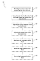
- FIGURE1 shows a schematic diagram illustrating a non-limiting embodiment of the electric heating method for recovering carbon fibers in CFRP.
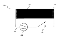
- FIGURES2A and2B show a setup diagram illustrating a non-limiting embodiment of the electric heating system for recovering carbon fibers in CFRP.
- FIGURE 2A shows a top view of the electric heating system;and
- FIGURE2B shows a side view of the electric heating system.
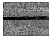
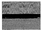
- FIGURES3A and3B show carbon fibers before and after recovery using a non-limiting embodiment of the electric heating method for recovering carbon fibers in CFRP,with a treatment voltage of10V and current of14A for15minutes.
- FIGURE 3A shows a digital photograph of the CFRPs before the treatment;and
- FIGURE3B shows a digital photograph of carbon fibers obtained after the treatment.
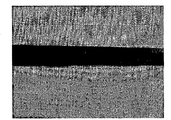
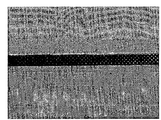
- FIGURES4A and4B show carbon fibers before and after recovery using a non-limiting embodiment of the electric heating method for recovering carbon fibers in CFRP,with a treatment voltage of12V and current of15A for5minutes.
- FIGURE4A shows a digital photograph of the CFRPs before the treatment;and
- FIGURE4B shows a digital photograph of carbon fibers obtained after the treatment.
- FIGURES5A and5B show carbon fibers before and after recovery using a non-limiting embodiment of the electric heating method for recovering carbon fibers with treatment voltage of10V and current of17A for30minutes.
- FIGURE5A shows a digital photograph of the CFRPs before the treatment;and
- FIGURE5B shows a digital photograph of carbon fibers obtained after the treatment.
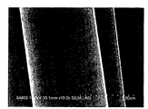
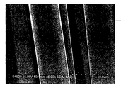
- FIGURES6A and6B show scanning electron microscope(SEM)images of carbon fibers recovered using a non-limiting embodiment of the electric heating method for recovering carbon fibers in CFRP after treatment with a voltage of10V and a current of 17A for30minutes.
- FIGURE6A shows the image of the carbon fibers at a magnification of10,000times;and
- FIGURE6B shows the image of the carbon fibers at a magnification of 5000times.
- Carbon fibers generally have good electrical conductivity,and may usually be distributed uniformly throughout a resin matrix of CFRPs.
- a carbon fiber-containing object such as a CFRP
- The“internal heating approach” can be achieved by passing an electric current through the carbon fibers to generate heat internally within the carbon fibers.Heat from the carbon fibers can then soften the surrounding resin matrix and separate the carbon fibers from the polymer matrix.
- the“internal heating approach” can effectively treat carbon fiber-containing objects, such as CFRPs,to obtain clean and well-ordered carbon fibers with properties that are substantially the same as the original carbon fibers before they were processed into CFRPs.
- the surface of the obtained carbon fibers can be substantially as smooth as the original carbon fibers.
- the surface of the obtained carbon fibers can be substantially free of damage.
- the obtained carbon fibers are substantially well-ordered.
- the obtained carbon fibers have substantially the same order of arrangement as the original carbon fibers.
- the methods disclosed herein can also be simple to operate and have minimal equipment requirements.
- the carbon fiber-containing object may include carbon fibers and resin.
- the method includes providing at least one object that includes carbon fibers and resin;and contacting the at least one object with an electric current to separate the carbon fibers from the resin.It will be appreciated that the carbon fibers can be recovered using only the providing and contacting steps,and can exclude other steps such as contacting the CFRP with one or more solvents,mechanical shearing or chopping the CFRP,and/or applying external heat to the CFRP.
- the method consists of the providing and contacting steps.
- the method consists essentially of the providing and contacting steps.
- FIGURE1 A non-limiting example of the method100of recovering carbon fibers in accordance with the disclosed embodiments is illustrated in the flow diagram shown in FIGURE1.As illustrated in FIGURE1,the method100can include one or more functions, operations or actions as illustrated by one or more operations110-170.
- Method100can begin at operation110,“Providing at least one object that includes carbon fibers and resin.”Operation110can be followed by operation120, “Contacting the object with an electric current to separate the carbon fibers from the resin.” Operation120can be followed by optional operation130,“Adjusting the voltage regulator of the electrical circuit.”Operation130can be followed by optional operation140,“Adjusting the power output of the electrical circuit.”Operation140can be followed by optional operation150,“Monitoring the temperature of the object.”Operation150can be followed by optional operation160,“Removing resin from the carbon fibers.”Operation160can be followed by optional operation170,“Recovering the separated carbon fibers.”
- operation110-170 are illustrated as being performed sequentially with operation110first and operation170last.It will be appreciated,however, that these operations can be combined and/or divided into additional or different operations as appropriate to suit particular embodiments.For example,additional operations can be added before,during or after one or more operations110-170.In some embodiments,one or more of the operations can be performed at about the same time.In some embodiments,the method only consists of operations110and120,but not any other operations. In some embodiments,the method consists essentially of operations110and120.In some embodiments,the method only consists of operations110,120and one of operations130- 170,but not any other operations. In some embodiments,the method only consists of operations110,120and two of operations130-170,but not any other operations. In some embodiments,the method only consists of operations110,120and one or more of operations 130-170,but not any other operations.
- the object is not particularly limited and can be CFRPs.
- the size of the CFRP is not particularly limited.
- the object can include a CFRP having a length of about1cm to about1m or more,and a width of about1cm to about1m or more.
- the object can include a small piece of CFRP.
- the size of the small piece of CFRP can be less than or equal to about30cm by1cm,for example less than or equal to 14 cm by3cm.
- the object can include a large piece of CFRP.
- the size of the large piece of CFRP can be greater than or equal to about 1m by1m.
- the object has a thickness of about1mm to about10cm or more.
- the object has a thickness of about1mm,about2mm,about3mm,about4 mm,about5mm,about6mm,about7mm,about8mm,about9mm,about1
- contacting the object with the electric current can be performed,for example in the absence of a solvent. In some embodiments,contacting the object with the electric current is performed in the absence of a solvent. In some embodiments,contacting the object with the electrical current is performed in the absence of one or both of mechanical shearing and chopping.Contacting of the object with the electric current can generate heat within the object.In some embodiments,contacting the object with the electric current generates heat within the carbon fibers of the object. In some embodiments,contacting the object with the electric current generates heat within the resin of the object.In some embodiments,the heat is evenly distributed within the object. In some embodiments,no heat is applied to the object from an external source. The external source can be a heated medium,such as a solvent or a gas,external to the object.In some embodiments,the solvent is a chemical solvent.In some embodiments,the gas is air.
- the amount of time for which the object is contacted with the electric current is not particularly limited.
- the electric current can heat the object for at least about3minutes.
- the electric current can heat the object for about1minute to about60minutes or more.
- the electric current can heat the object for about1minute,about2minutes,about3minutes,about4minutes,about5 minutes,about6minutes,about7minutes,about8minutes,about9minutes,about10 minutes,about15minutes,about20minutes,about30minutes,about60minutes,or an amount of time between any two of these values.
- the electric current can heat the object for less than or equal to about10minutes or5minutes.
- the electric current can heat the object for less than or equal to about1minute.
- the electric current can heat the object for about5minutes to about30 minutes.In some embodiments,the electric current heats the object until the resin has been completely separated from the carbon fibers.
- the electric current is provided by an electrical circuit.
- the electrical circuit includes a voltage regulator.
- a voltage regulator typically receives a supply voltage and provides a regulated(for example,substantially constant)output voltage to an electrical circuit.
- the type of voltage regulator is not particularly limited. Any suitable voltage regulator can be used for the electrical circuit,for example, a simple voltage regulator, a feedback voltage regulator,an electromechanical voltage regulator, a coil-rotation AC voltage regulator,an AC voltage stabilizer, a DC voltage stabilizer, a linear regulator,a switching regulator, a silicon-controlled rectifier(SCR) regulator,or a combination thereof.
- the voltage regulator is a low voltage regulator.
- the low voltage regulator for example,is configured to regulate a supply voltage of about1V to about50V.
- the low voltage regulator is configured to regulate a supply voltage of about4V to about12V.
- the electrical circuit includes a power source.In some embodiments,the electrical circuit includes at least
- contacting the object with the electric current can include connecting at least two electrodes of an electrical circuit to at least two contact points on the object.
- the at least two electrodes can be connected to the at least two contact points on the object directly.
- the at least two electrodes are connected to the at least two contact points on the object through one or more electrical circuit clamps.
- the at least two electrodes are connected to the at least two contact points on the object through a conductive foil,such as a metal foil.
- Non-limiting examples of the metal foil include a copper foil,an aluminum foil or any combination thereof.Once connected,the electrical circuit is turned on. The current in the electrical circuit,as well as the treatment time,can be controlled by adjusting a voltage of the electrical circuit,for example through a voltage regulator.
- contacting the object with the electric current can include applying a voltage of about4V to about12V across at least two contact points on the object.
- contacting the object with the electric current can include supplying a power of about50W to about200W to an electrical circuit in electrical communication with the object.
- the magnitude of the electric current produced from the electrical circuit is not particularly limited.
- the electric current can have a current of about1A to about200A or more.
- the electric current can have a current of about1A,about2A,about3A,about4A,about5A,about6A,about7A,about8A, about9A,about10A,about11A,about12A,about13A,about14A,about15A,about 16A,about17A,about18A,about19A,about20A,about30A,about40A,about50A, about60A,about70A,about80A,about90A,about100A,about200A,or a current between any two of these values.
- the electric current can have a current of about14A to about20A.
- the electric current is an AC current.
- the electric current is a DC current.
- the method can consist essentially of operation110, “Providing at least one object that includes carbon fibers and resin,”and operation120, “Contacting the object with an electric current to separate the carbon fibers from the resin.” In some embodiments, the method can consist of operation110,“Providing at least one object that includes carbon fibers and resin,”and operation120,“Contacting the object with an electric current to separate the carbon fibers from the resin.”
- a voltage regulator can be used to control the voltage applied across at least two contact points on the object and hence the electric current passing through the object.
- the voltage applied is not particularly limited.
- contacting the object with the electric current can include applying a voltage of about1V to about240V or more across at least two contact points on the object.
- contacting the object with the electric current can include applying a voltage of about1V,about2V,about3V, about4V,about5V,about6V,about7V,about8V,about9V,about10V,about11V, about12V,about13V,about14V,about15V,about16V,about17V,about18V,about 19V,about20V,about30V,about40V,about50V,about60V,about70V,about80V, about90V,about100V,about200V,about240V,or a voltage between any two of these values across at least two contact points on the object.
- a voltage between any two of these values across at least two contact points on the object
- the power supplied to the electrical circuit can vary.
- the power can be at least about10watts(W).
- contact the object with the electric current includes supplying a power of about10W to about10000W or more.
- the electrical circuit can be supplied with a power of about10W,about20W,about30W, about40W,about50W,about60W,about70W,about80W,about90W,about100W, about110W,about120W,about140W,about160W,about180W,about200W,about 500W,about1000W,about2000W,about3000W,about4000W,about5000W,about 6000W,about7000W,about8000W,about9000W,about10000W,or a power between any two of these values.
- contact the object with the electric current includes supplying a power of about50W to about200W.
- the temperature of the object may be monitored using a variety of techniques known in the art.
- an infrared thermometer can be used to monitor the temperature of the object.
- the electric current can generate heat within the carbon fibers of the object to a certain temperature.Without being bound by theory,the electric current heats the object due to the electrical conductivity of the carbon fibers of the object.
- the temperature can be regulated by the power of the electrical circuit.
- the temperature can be regulated by adjusting the voltage of the electrical circuit.
- the temperature can be regulated by the current of the electrical circuit.
- the temperature of the object is achieved by adjusting the power,voltage,current,or a combination of the electrical circuit.
- adjusting the voltage of the electrical circuit includes adjusting the voltage regulator.
- the temperature of the object is kept constant through the contacting of the object with the electrical current.
- the temperature of the object is changed during the contacting of the object with the electrical current.
- the temperature of the object resulting from internal heating of the carbon fibers by the electric current is not particularly limited.
- the electric current heats the object to a temperature of about300°C to about600°C or higher.
- the electric current heats the object to a temperature of about300°C,about 320°C,about350°C,about400°C,about450°C,about500°C,about550°C,about560 °C,about600°C,or a temperature between any two of these values.
- the electric current heats the object to a temperature of at least about300°C,at least about 350°C,at least about400°C,at least about450°C,at least about500°C,at least about550 °C,or at least about600°C or higher.
- the electric current heats the object to a temperature of about320°C to about560°C.
- the resin can be removed from the carbon fibers by hot airflow.
- the resin includes an epoxy,polyester,vinyl ester,nylon,phenolic resin,and urea resin.
- the methods disclosed herein can also include,in some embodiments, optional operation170,“Recovering the separated carbon fibers.”
- the carbon fibers are fully separated from the resin after the contacting step.
- the carbon fibers substantially maintain the original order of arrangement of the carbon fibers after the contacting step.
- the recovered carbon fibers can be collected by using a smooth plate.
- the size of the plate can be larger than the object.
- the size of the recovered carbon fiber pieces is not particularly limited.For example,the size of the recovered carbon fiber pieces can be about1cm to about30cm.
- the size of the recovered carbon fiber pieces can be about1cm,about2cm,about3cm,about4cm,about5cm,about6cm,about7cm,about 8cm,about9cm,about10cm,about11cm,about12cm,about13cm,about14cm,about 15cm,about16cm,about17cm,about18cm,
- the system includes an electrical circuit configured to contact an object with an electric current,the object including carbon fibers and resin,wherein the electric current separates the carbon fibers from the resin.
- the electrical circuit includes at least two electrodes configured to electrically connect to at least two contact points on the object.
- the electrical circuit includes a power source.
- the electrical circuit includes a voltage regulator.
- the voltage regulator is a low voltage regulator.
- the electrical circuit includes a switch.
- the two electrodes are connected to the two contact points on the object through a conductive foil,such as a copper foil,an aluminum foil or both.
- the electric current source can be configured to contact the object with the electric current in the absence of a solvent.
- the object201 including carbon fibers and resin is not particularly limited.
- the object can include CFRPs.
- the size of the CFRP is not particularly limited.
- the object can include a CFRP having a length of about1 cm to about1m or more,and a width of about1cm to about1m or more.
- the object can include a small piece of CFRP.
- the size of the small piece of CFRP can be less than or equal to about30cm by1cm,for example less than or equal to about14cm by3cm.
- the object can include a large piece of CFRP.
- the size of the large piece of CFRP can be greater than or equal to about1m by1m.
- the object has a thickness of about1mm to about10cm or more.
- the object has a thickness of about1mm,about2mm,about3mm, about4mm,about5mm,about6mm,about7mm,about8mm,about9mm,about1cm, about2cm,about3cm,about4cm,about5cm,about6cm,about7cm,about8cm,about 9cm,about10cm,or a thickness between any two of these values.
- the object has a thickness of about1mm to about3mm.
- the resin is a thermoset resin or a thermoplastic polymer.Non-limiting examples of the resin include epoxy,polyester,vinyl ester,nylon,phenolic resin,and urea resin.
- the object including carbon fibers and resin may include other components,such as aramid fiber,aluminum fiber
- the electric current is provided by an electrical circuit202.
- the electrical circuit202 can include a voltage regulator.
- the type of voltage regulator is not particularly limited. Any suitable voltage regulator can be used for the electrical circuit,for example, a simple voltage regulator, a feedback voltage regulator, an electromechanical voltage regulator, a coil-rotation AC voltage regulator,an AC voltage stabilizer, a DC voltage stabilizer, a linear regulator, a switching regulator, a SCR regulator, etc.,or a combination thereof.
- the voltage regulator is a low voltage regulator.
- the electrical circuit202can include a power source204.
- the electrical circuit202can include a switch205for turning on or turning off the electrical circuit.
- the electrical circuit202 can include two electrodes that are configured to connect to two contact points on the object201.
- the electrodes are configured to be connected to the two contact points on the object201 directly.
- the electrodes are configured to be connected to the object 201through a conductive foil203.
- the conductive foil can be,for example, a copper foil,an aluminum foil,or both.
- the voltage of the electric current produced from the electrical circuit202 is not particularly limited.
- the electrical circuit202 is configured to apply a voltage of about1V to about240V or more across at least two contact points on the object.
- the electrical circuit202is configured to apply a voltage of about1V, about2V,about3V,about4V,about5V,about6V,about7V,about8V,about9V, about10V,about11V,about12V,about13V,about14V,about15V,about16V,about 17V,about18V,about19V,about20V,about30V,about40V,about50V,about60V, about70V,about80V,about90V,about100V,about200V,about240V,or a voltage between any two of these values across at least two contact points on the object.
- the electrical circuit202is configured to apply a voltage of about4V to about 12V across at least two contact points on the object.
- the current of the electric current produced from the electrical circuit202 is not particularly limited.
- the electric current can have a current of about1A to about200A or more.
- the electric current can have a current of about1A,about2A,about3A,about4A,about5A,about6A,about7A,about8A, about9A,about10A,about11A,about12A,about13A,about14A,about15A,about 16A,about17A,about18A,about19A,about20A,about30A,about40A,about50A, about60A,about70A,about80A,about90A,about100A,about200A,or a current between any two of these values.
- the electric current can have a current of about14A to about20A.
- the electric current is an AC current.
- the electric current is a DC current.
- the amount of time for which the electric current can be configured to heat the object201 is not particularly limited.
- the electric current can heat the object201for about1minute,about2minutes,about3 minutes,about4minutes,about5minutes,about6minutes,about7minutes,about8 minutes,about9minutes,about10minutes,about15minutes,about20minutes,about30 minutes,about60minutes,or an amount of time between any two of these values.
- the electric current can heat the object201for about5minutes.
- the electric current can heat the object201for about15minutes.
- the electric current can heat the object201for about30minutes.
- the power source204from which the electric current is produced is not particularly limited.
- the power source204 can be an electric generator or an electric battery.
- the power of the electric current produced from the power source204can vary.
- the electrical circuit is configured to operate at a power of about10watts(W).
- the electrical circuit is configured to operate at a power of about10W to about10000W or more.
- the electrical circuit is configured to operate at a power of about10W,about20W,about30W,about40W,about50W,about60W,about70W, about80W,about90W,about100W,about110W,about120W,about140W,about160 W,about180W,about200W,about500W,about1000W,about2000W,about3000W, about4000W,about5000W,about6000W,about7000W,about8000W,about9000W, about10000W,or a power between any two of these values.
- the electrical circuit is configured to operate at a power of about10watts(W).
- the temperature of the object201 is not particularly limited.
- the electric current is configured to heat the object201to a temperature of about300°C to about600°C or higher.
- the electric current is configured to heat the object201to a temperature of about300°C,about320°C,about350°C,about400°C, about450°C,about500°C,about550°C,about560°C,about600°C,or a temperature between any two of these values.
- the electric current is configured to heat the object201to a temperature of at least about300°C,at least about350°C,at least about400°C,at least about450°C,at least about500°C,at least about550°C,or at least about600°C or higher.
- the electric current is configured to heat the object201to a temperature of320°C to560°C.
- the“internal heating approach” uses an inert atmosphere-like sealed environment formed by the CFRP itself,and therefore does not require addition of a protective atmosphere during the treatment as typically used in“external heating” approaches such as the pyrolysis technology; (3)the methods are simple with short treatment time,and no specialized skills are required to operate;(4)the carbon fibers recovered by the methods may be well-ordered or have substantially the same order of arrangement as the original carbon fibers,and the mechanical performance of the recovered carbon fibers is suitable for reprocessing and utilization;and(5)the“internal heating approach”can recover carbon fibers from both thick and thin pieces of CFRPs due to the uniform distribution of the carbon fibers in the resin matrix of the CFRP and the heat generated within each fiber when the electrical current passes through the fibers.
- a strip of carbon fiber reinforced polymer(CFRP)sample having a size of 330mm ⁇ 10mm ⁇ 3mm was taken and connected to two electrodes of an electrical circuit.
- the current of the electrical circuit was controlled at14A by a low voltage regulator,and the corresponding voltage was10V.
- the treatment time was15minutes.It can be seen,by comparing the sample before treatment(FIGURE3A)and after treatment(FIGURE3B) that the carbon fibers had fully delaminated from the resin and substantially maintained a well-ordered arrangement after the treatment.
- the carbon fibers after the treatment also showed a substantially smooth surface.
- This example showed that the method disclosed herein can be used to efficiently and quickly to recover carbon fibers that is well-ordered, substantially free of defects and substantially free of residual resin.
- the example also showed that the carbon fiber can be recovered from the CFRP sample without other additional steps such as contacting the CFRP sample with solvents,mechanical shearing or chopping the CFRP sample,or applying external heating to the CFRP
- a strip of CFRP sample having a size of about360mm ⁇ 10mm ⁇ 3mm was taken and connected to two electrodes of an electrical circuit.
- the voltage was controlled at12V by a low voltage regulator to obtain a current of15A,and the treatment time was5minutes.It can be seen,by comparing the sample before treatment(FIGURE4A) and after treatment(FIGURE4B)that the carbon fibers had fully delaminated from the resin after the treatment,and substantially maintained a well-ordered arrangement after the treatment.
- the carbon fibers after the treatment also showed a substantially smooth surface.
- a strip of CFRP sample having a size of about300mm ⁇ 10mm ⁇ 3mm was taken and connected to two electrodes of an electrical circuit.
- the voltage was controlled at10V by a low voltage regulator,and the corresponding current was17A.
- the treatment time was30minutes.Carbon fibers with epoxy resin removed was thus recovered.
- FIGURES6A-B Digital photographs of the sample before(FIGURE5A)and after treatment(FIGURE5B) are shown,from which it can be seen that the carbon fibers were delaminated from the resin and substantially maintained a well-ordered arrangement.
- SEM images of the carbon fibers are shown in FIGURES6A-B,from which it can be seen that the carbon fiber filaments were completely separated with very smooth surface and without any residual polymer or obvious damage.
- the method disclosed herein can be used to efficiently and quickly recover carbon fibers with good quality(well-ordered,free of defects and without residual resin)from carbon fiber reinforced resin.
- the carbon fiber can be recovered from the CFRP sample without other additional steps such as contacting the CFRP sample with solvents,mechanical shearing or chopping the CFRP sample,or applying external heating to the CFRP sample.
Landscapes
- Chemical & Material Sciences (AREA)
- Chemical Kinetics & Catalysis (AREA)
- Health & Medical Sciences (AREA)
- Medicinal Chemistry (AREA)
- Polymers & Plastics (AREA)
- Organic Chemistry (AREA)
- Life Sciences & Earth Sciences (AREA)
- Sustainable Development (AREA)
- General Chemical & Material Sciences (AREA)
- Engineering & Computer Science (AREA)
- Textile Engineering (AREA)
- Separation, Recovery Or Treatment Of Waste Materials Containing Plastics (AREA)
Abstract
Disclosed herein are methods and systems for recovering carbon fibers from objects. The object may include carbon fibers and resin. The object may be contacted with an electric current to separate the carbon fibers from the resin.
Description
Unless otherwise indicated herein,the materials described in this section
are not prior art to the claims in this application and are not admitted to be prior art by
inclusion in this section.
Current methods for recovering carbon fibers from carbon fiber reinforced
polymers(CFRP)waste generally include mechanical pulverization,chemical solvent
treatment,pyrolysis,treatment with supercritical fluids,or exposure to microwave.Each of
these methods have its own shortcomings.For example,the mechanical pulverization
method may result in a mixed debris of polymers and randomly ordered carbon fibers,which
may be of low value for recovery.The supercritical fluid method,microwave method and
pyrolysis method may all require specialized high pressure or temperature resistant devices,
and the use of these methods can significantly increase the cost of carbon fiber recovery.
The chemical solvent method would leave a large amount of organic solvent waste or nitric
acid waste with dissolved polymers after the treatment,producing significant“secondary
pollution”which can be difficult to dispose.Moreover,the above-mentioned methods have
varying degrees of complexity in their operating procedures.
During the process of carbon fiber recovery,many of the existing methods
as described above require external sources of heating.The external heating can be achieved
by applying heat external to the CFRP sample,either directly to the CFRP sample or through
a heated medium(solvent or hot air)external to the CFRP sample.The external heating
typically causes uneven heating of the CFRP sample which can overheat outer surfaces of the
CFRP sample and damage the carbon fibers that are recovered.Particularly for large and
thick samples,they may require a longer processing time and may result in the carbon fibers
in the outer portions of the CFRP sample to be burnt while the internal portions of the sample
have not been completely treated.A prolonged heat treatment may significantly reduce the
performance of carbon fibers.Another disadvantage of the above methods is that the order of
arrangement of the carbon fibers obtained from the treatment may easily be disrupted,which
is not conducive to the re-processing and re-use of the carbon fibers.The performance of the
recovered carbon fibers can be greatly improved if they are well-ordered.There is therefore a
need for an effective and simple method for recovering well-ordered carbon fibers from
carbon fiber-containing objects,such as CFRP.
SUMMARY
In one aspect,a method of recovering carbon fibers from at least one
object includes:providing at least one object containing carbon fibers and resin;and
contacting the at least one object with an electric current to separate the carbon fibers from
the resin.
In another aspect,a system for recovering carbon fibers from at least one
object includes:an electrical circuit configured to contact at least one object with an electric
current,the object containing carbon fibers and resin,wherein the electric current separates
the carbon fibers from the resin.
The foregoing and other features of the present disclosure will become
more fully apparent from the following description and appended claims,taken in
conjunction with the accompanying drawings.Understanding that these drawings depict
only several embodiments in accordance with the disclosure and are not to be considered
limiting of its scope,the disclosure will be described with additional specificity and detail
through use of the accompanying drawings.
FIGURE1shows a schematic diagram illustrating a non-limiting
embodiment of the electric heating method for recovering carbon fibers in CFRP.
FIGURES2A and2B show a setup diagram illustrating a non-limiting
embodiment of the electric heating system for recovering carbon fibers in CFRP.FIGURE
2A shows a top view of the electric heating system;and FIGURE2B shows a side view of
the electric heating system.
FIGURES3A and3B show carbon fibers before and after recovery using
a non-limiting embodiment of the electric heating method for recovering carbon fibers in
CFRP,with a treatment voltage of10V and current of14A for15minutes.FIGURE 3A
shows a digital photograph of the CFRPs before the treatment;and FIGURE3B shows a
digital photograph of carbon fibers obtained after the treatment.
FIGURES4A and4B show carbon fibers before and after recovery using
a non-limiting embodiment of the electric heating method for recovering carbon fibers in
CFRP,with a treatment voltage of12V and current of15A for5minutes.FIGURE4A
shows a digital photograph of the CFRPs before the treatment;and FIGURE4B shows a
digital photograph of carbon fibers obtained after the treatment.
FIGURES5A and5B show carbon fibers before and after recovery using
a non-limiting embodiment of the electric heating method for recovering carbon fibers with
treatment voltage of10V and current of17A for30minutes.FIGURE5A shows a digital
photograph of the CFRPs before the treatment;and FIGURE5B shows a digital photograph
of carbon fibers obtained after the treatment.
FIGURES6A and6B show scanning electron microscope(SEM)images
of carbon fibers recovered using a non-limiting embodiment of the electric heating method
for recovering carbon fibers in CFRP after treatment with a voltage of10V and a current of
17A for30minutes.FIGURE6A shows the image of the carbon fibers at a magnification
of10,000times;and FIGURE6B shows the image of the carbon fibers at a magnification of
5000times.
In the following detailed description,reference is made to the
accompanying drawings,which form a part hereof.In the drawings,similar symbols
typically identify similar components,unless context dictates otherwise.The illustrative
embodiments described in the detailed description,drawings,and claims are not meant to be
limiting.Other embodiments may be used,and other changes may be made,without
departing from the spirit or scope of the subject matter presented here.It will be readily
understood that the aspects of the present disclosure,as generally described herein,and
illustrated in the Figures,can be arranged,substituted,combined,and designed in a wide
variety of different configurations,all of which are explicitly contemplated and make part of
this disclosure.
Carbon fibers generally have good electrical conductivity,and may
usually be distributed uniformly throughout a resin matrix of CFRPs.Taking advantage of
such properties,some embodiments disclosed herein provide methods of recovering carbon
fibers from a carbon fiber-containing object,such as a CFRP,through an“internal heating
approach”.The“internal heating approach”can be achieved by passing an electric current
through the carbon fibers to generate heat internally within the carbon fibers.Heat from the
carbon fibers can then soften the surrounding resin matrix and separate the carbon fibers
from the polymer matrix.
As described herein,the“internal heating approach”can effectively treat
carbon fiber-containing objects,such as CFRPs,to obtain clean and well-ordered carbon
fibers with properties that are substantially the same as the original carbon fibers before they
were processed into CFRPs.For example,the surface of the obtained carbon fibers can be
substantially as smooth as the original carbon fibers.In some embodiments,the surface of
the obtained carbon fibers can be substantially free of damage.In some embodiments,the
obtained carbon fibers are substantially well-ordered.In some embodiments,the obtained
carbon fibers have substantially the same order of arrangement as the original carbon fibers.
The methods disclosed herein can also be simple to operate and have minimal equipment
requirements.
Methods of recovering carbon fibers
Methods of recovering carbon fibers from at least one carbon fiber-
containing object are provided herein.The carbon fiber-containing object may include
carbon fibers and resin.In some embodiments,the method includes providing at least one
object that includes carbon fibers and resin;and contacting the at least one object with an
electric current to separate the carbon fibers from the resin.It will be appreciated that the
carbon fibers can be recovered using only the providing and contacting steps,and can
exclude other steps such as contacting the CFRP with one or more solvents,mechanical
shearing or chopping the CFRP,and/or applying external heat to the CFRP.In some
embodiments,the method consists of the providing and contacting steps.In some
embodiments,the method consists essentially of the providing and contacting steps.
A non-limiting example of the method100of recovering carbon fibers in
accordance with the disclosed embodiments is illustrated in the flow diagram shown in
FIGURE1.As illustrated in FIGURE1,the method100can include one or more functions,
operations or actions as illustrated by one or more operations110-170.
Method100can begin at operation110,“Providing at least one object that
includes carbon fibers and resin.”Operation110can be followed by operation120,
“Contacting the object with an electric current to separate the carbon fibers from the resin.”
Operation120can be followed by optional operation130,“Adjusting the voltage regulator of
the electrical circuit.”Operation130can be followed by optional operation140,“Adjusting
the power output of the electrical circuit.”Operation140can be followed by optional
operation150,“Monitoring the temperature of the object.”Operation150can be followed
by optional operation160,“Removing resin from the carbon fibers.”Operation160can be
followed by optional operation170,“Recovering the separated carbon fibers.”
In FIGURE1,operations110-170are illustrated as being performed
sequentially with operation110first and operation170last.It will be appreciated,however,
that these operations can be combined and/or divided into additional or different operations
as appropriate to suit particular embodiments.For example,additional operations can be
added before,during or after one or more operations110-170.In some embodiments,one or
more of the operations can be performed at about the same time.In some embodiments,the
method only consists of operations110and120,but not any other operations.In some
embodiments,the method consists essentially of operations110and120.In some
embodiments,the method only consists of operations110,120and one of operations130-
170,but not any other operations.In some embodiments,the method only consists of
operations110,120and two of operations130-170,but not any other operations.In some
embodiments,the method only consists of operations110,120and one or more of operations
130-170,but not any other operations.
At operation110,“Providing at least one object that includes carbon fibers
and resin,”the object is not particularly limited and can be CFRPs.The size of the CFRP is
not particularly limited.For example,the object can include a CFRP having a length of
about1cm to about1m or more,and a width of about1cm to about1m or more.In some
embodiments,the object can include a small piece of CFRP.The size of the small piece of
CFRP can be less than or equal to about30cm by1cm,for example less than or equal to 14
cm by3cm.In some embodiments,the object can include a large piece of CFRP.The size
of the large piece of CFRP can be greater than or equal to about 1m by1m.In some
embodiments,the object has a thickness of about1mm to about10cm or more.In some
embodiments,the object has a thickness of about1mm,about2mm,about3mm,about4
mm,about5mm,about6mm,about7mm,about8mm,about9mm,about1cm,about2
cm,about3cm,about4cm,about5cm,about6cm,about7cm,about8cm,about9cm,
about10cm,or a thickness between any two of these values.In some embodiments,the
object has a thickness of about1mm to about3mm.The type of the resin can also vary.In
some embodiments,the resin is a thermoset resin or a thermoplastic polymer.Non-limiting
examples of the resin include epoxy,polyester,vinyl ester,nylon,phenolic resin,and urea
resin.The object may further include other components,such as aramid fiber,aluminum
fiber,glass fiber,or any combination thereof.
At operation120,“Contacting the object with an electric current to
separate the carbon fibers from the resin,”contacting the object with the electric current can
be performed,for example in the absence of a solvent.In some embodiments,contacting the
object with the electric current is performed in the absence of a solvent.In some
embodiments,contacting the object with the electrical current is performed in the absence of
one or both of mechanical shearing and chopping.Contacting of the object with the electric
current can generate heat within the object.In some embodiments,contacting the object with
the electric current generates heat within the carbon fibers of the object.In some
embodiments,contacting the object with the electric current generates heat within the resin
of the object.In some embodiments,the heat is evenly distributed within the object.In
some embodiments,no heat is applied to the object from an external source.The external
source can be a heated medium,such as a solvent or a gas,external to the object.In some
embodiments,the solvent is a chemical solvent.In some embodiments,the gas is air.
The amount of time for which the object is contacted with the electric
current is not particularly limited.For example the electric current can heat the object for at
least about3minutes.In some embodiments,the electric current can heat the object for
about1minute to about60minutes or more.For example,the electric current can heat the
object for about1minute,about2minutes,about3minutes,about4minutes,about5
minutes,about6minutes,about7minutes,about8minutes,about9minutes,about10
minutes,about15minutes,about20minutes,about30minutes,about60minutes,or an
amount of time between any two of these values.In some embodiments,the electric current
can heat the object for less than or equal to about10minutes or5minutes.In some
embodiments,the electric current can heat the object for less than or equal to about1minute.
In some embodiments,the electric current can heat the object for about5minutes to about30
minutes.In some embodiments,the electric current heats the object until the resin has been
completely separated from the carbon fibers.
The source from which the electric current is produced is not particularly
limited.In some embodiments,the electric current is provided by an electrical circuit.In
some embodiments,the electrical circuit includes a voltage regulator.A voltage regulator
typically receives a supply voltage and provides a regulated(for example,substantially
constant)output voltage to an electrical circuit.The type of voltage regulator is not
particularly limited.Any suitable voltage regulator can be used for the electrical circuit,for
example,a simple voltage regulator,a feedback voltage regulator,an electromechanical
voltage regulator,a coil-rotation AC voltage regulator,an AC voltage stabilizer,a DC
voltage stabilizer,a linear regulator,a switching regulator,a silicon-controlled rectifier(SCR)
regulator,or a combination thereof.In some embodiments,the voltage regulator is a low
voltage regulator.The low voltage regulator,for example,is configured to regulate a supply
voltage of about1V to about50V.In some embodiments,the low voltage regulator is
configured to regulate a supply voltage of about4V to about12V.In some embodiments,the
electrical circuit includes a power source.In some embodiments,the electrical circuit
includes at least two electrodes that are connected to at least two contact points on the object.
In some embodiments,contacting the object with the electric current can
include connecting at least two electrodes of an electrical circuit to at least two contact points
on the object.In some embodiments,the at least two electrodes can be connected to the at
least two contact points on the object directly.In some embodiments,the at least two
electrodes are connected to the at least two contact points on the object through one or more
electrical circuit clamps.In some embodiments,the at least two electrodes are connected to
the at least two contact points on the object through a conductive foil,such as a metal foil.
Non-limiting examples of the metal foil include a copper foil,an aluminum foil or any
combination thereof.Once connected,the electrical circuit is turned on.The current in the
electrical circuit,as well as the treatment time,can be controlled by adjusting a voltage of the
electrical circuit,for example through a voltage regulator.In some embodiments,contacting
the object with the electric current can include applying a voltage of about4V to about12V
across at least two contact points on the object.In some embodiments,contacting the object
with the electric current can include supplying a power of about50W to about200W to an
electrical circuit in electrical communication with the object.
The magnitude of the electric current produced from the electrical circuit
is not particularly limited.For example,the electric current can have a current of about1A
to about200A or more.In some embodiments,the electric current can have a current of
about1A,about2A,about3A,about4A,about5A,about6A,about7A,about8A,
about9A,about10A,about11A,about12A,about13A,about14A,about15A,about
16A,about17A,about18A,about19A,about20A,about30A,about40A,about50A,
about60A,about70A,about80A,about90A,about100A,about200A,or a current
between any two of these values.In some embodiments,the electric current can have a
current of about14A to about20A.In some embodiments,the electric current is an AC
current.In some embodiments,the electric current is a DC current.
In some embodiments,the method can consist essentially of operation110,
“Providing at least one object that includes carbon fibers and resin,”and operation120,
“Contacting the object with an electric current to separate the carbon fibers from the resin.”
In some embodiments,the method can consist of operation110,“Providing at least one
object that includes carbon fibers and resin,”and operation120,“Contacting the object with
an electric current to separate the carbon fibers from the resin.”
At optional operation130,“Adjusting the voltage regulator of the
electrical circuit,”a voltage regulator can be used to control the voltage applied across at
least two contact points on the object and hence the electric current passing through the
object.The voltage applied is not particularly limited.For example,contacting the object
with the electric current can include applying a voltage of about1V to about240V or more
across at least two contact points on the object.In some embodiments,contacting the object
with the electric current can include applying a voltage of about1V,about2V,about3V,
about4V,about5V,about6V,about7V,about8V,about9V,about10V,about11V,
about12V,about13V,about14V,about15V,about16V,about17V,about18V,about
19V,about20V,about30V,about40V,about50V,about60V,about70V,about80V,
about90V,about100V,about200V,about240V,or a voltage between any two of these
values across at least two contact points on the object.In some embodiments,contacting the
object with the electric current can include applying a voltage of about4V to about12V
across at least two contact points on the object.
At optional operation140,“Adjusting the power output of the electrical
circuit,”the power supplied to the electrical circuit can vary.For example,the power can be
at least about10watts(W).In some embodiments,contacting the object with the electric
current includes supplying a power of about10W to about10000W or more.For example,
the electrical circuit can be supplied with a power of about10W,about20W,about30W,
about40W,about50W,about60W,about70W,about80W,about90W,about100W,
about110W,about120W,about140W,about160W,about180W,about200W,about
500W,about1000W,about2000W,about3000W,about4000W,about5000W,about
6000W,about7000W,about8000W,about9000W,about10000W,or a power between
any two of these values.In some embodiments,contacting the object with the electric
current includes supplying a power of about50W to about200W.
At optional operation150,“Monitoring the temperature of the object,”the
temperature of the object may be monitored using a variety of techniques known in the art.
For example,an infrared thermometer can be used to monitor the temperature of the object.
In some embodiments,the electric current can generate heat within the
carbon fibers of the object to a certain temperature.Without being bound by theory,the
electric current heats the object due to the electrical conductivity of the carbon fibers of the
object.In some embodiments,the temperature can be regulated by the power of the
electrical circuit.In some embodiments,the temperature can be regulated by adjusting the
voltage of the electrical circuit.In some embodiments,the temperature can be regulated by
the current of the electrical circuit.In some embodiments,the temperature of the object is
achieved by adjusting the power,voltage,current,or a combination of the electrical circuit.
In some embodiments,adjusting the voltage of the electrical circuit includes adjusting the
voltage regulator.In some embodiments,the temperature of the object is kept constant
through the contacting of the object with the electrical current.In some embodiments,the
temperature of the object is changed during the contacting of the object with the electrical
current.
The temperature of the object resulting from internal heating of the carbon
fibers by the electric current is not particularly limited.For example,the electric current
heats the object to a temperature of about300℃ to about600℃ or higher.In some
embodiments,the electric current heats the object to a temperature of about300℃,about
320℃,about350℃,about400℃,about450℃,about500℃,about550℃,about560
℃,about600℃,or a temperature between any two of these values.In some embodiments,
the electric current heats the object to a temperature of at least about300℃,at least about
350℃,at least about400℃,at least about450℃,at least about500℃,at least about550
℃,or at least about600℃ or higher.In some embodiments,the electric current heats the
object to a temperature of about320℃ to about560℃.
At optional operation160,“Removing resin from the carbon fibers,”the
resin can be removed from the carbon fibers by hot airflow.Non-limiting examples of the
resin includes an epoxy,polyester,vinyl ester,nylon,phenolic resin,and urea resin.
The methods disclosed herein can also include,in some embodiments,
optional operation170,“Recovering the separated carbon fibers.”In some embodiments,the
carbon fibers are fully separated from the resin after the contacting step.In some
embodiments,the carbon fibers substantially maintain the original order of arrangement of
the carbon fibers after the contacting step.In some embodiments,the recovered carbon
fibers can be collected by using a smooth plate.In some embodiments,the size of the plate
can be larger than the object.The size of the recovered carbon fiber pieces is not particularly
limited.For example,the size of the recovered carbon fiber pieces can be about1cm to
about30cm.In some embodiments,the size of the recovered carbon fiber pieces can be
about1cm,about2cm,about3cm,about4cm,about5cm,about6cm,about7cm,about
8cm,about9cm,about10cm,about11cm,about12cm,about13cm,about14cm,about
15cm,about16cm,about17cm,about18cm,about19cm,about20cm,about25cm,
about30cm,or a size between any two of these values.In some embodiments,the size of
the recovered carbon fiber pieces can be greater than about30cm.
Systems for recovering carbon fibers
Systems for recovering carbon fibers are disclosed herein.In some
embodiments,the system includes an electrical circuit configured to contact an object with
an electric current,the object including carbon fibers and resin,wherein the electric current
separates the carbon fibers from the resin.In some embodiments,the electrical circuit
includes at least two electrodes configured to electrically connect to at least two contact
points on the object.In some embodiments,the electrical circuit includes a power source.In
some embodiments,the electrical circuit includes a voltage regulator.In some embodiments,
the voltage regulator is a low voltage regulator.In some embodiments,the electrical circuit
includes a switch.In some embodiments,the two electrodes are connected to the two contact
points on the object through a conductive foil,such as a copper foil,an aluminum foil or both.
In some embodiments,the electric current source can be configured to contact the object with
the electric current in the absence of a solvent.
A non-limiting example of the system200for recovering carbon fibers in
accordance with the present disclosure is illustrated in FIGURE2.As illustrated in
FIGURE2,the system200can include one or more components as illustrated by201-205.
The object201including carbon fibers and resin is not particularly limited.
In some embodiments,the object can include CFRPs.The size of the CFRP is not
particularly limited.For example,the object can include a CFRP having a length of about1
cm to about1m or more,and a width of about1cm to about1m or more.In some
embodiments,the object can include a small piece of CFRP.The size of the small piece of
CFRP can be less than or equal to about30cm by1cm,for example less than or equal to
about14cm by3cm.In some embodiments,the object can include a large piece of CFRP.
The size of the large piece of CFRP can be greater than or equal to about1m by1m.In
some embodiments,the object has a thickness of about1mm to about10cm or more.In
some embodiments,the object has a thickness of about1mm,about2mm,about3mm,
about4mm,about5mm,about6mm,about7mm,about8mm,about9mm,about1cm,
about2cm,about3cm,about4cm,about5cm,about6cm,about7cm,about8cm,about
9cm,about10cm,or a thickness between any two of these values.In some embodiments,
the object has a thickness of about1mm to about3mm.In some embodiments,the resin is a
thermoset resin or a thermoplastic polymer.Non-limiting examples of the resin include
epoxy,polyester,vinyl ester,nylon,phenolic resin,and urea resin.The object including
carbon fibers and resin may include other components,such as aramid fiber,aluminum fiber,
glass fiber,or any combination thereof.
The source from which the electric current is produced is not particularly
limited.In some embodiments,the electric current is provided by an electrical circuit202.
In some embodiments,the electrical circuit202can include a voltage regulator.The type of
voltage regulator is not particularly limited.Any suitable voltage regulator can be used for
the electrical circuit,for example,a simple voltage regulator,a feedback voltage regulator,
an electromechanical voltage regulator,a coil-rotation AC voltage regulator,an AC voltage
stabilizer,a DC voltage stabilizer,a linear regulator,a switching regulator,a SCR regulator,
etc.,or a combination thereof.In some embodiments,the voltage regulator is a low voltage
regulator.
In some embodiments,the electrical circuit202can include a power
source204.In some embodiments,the electrical circuit202can include a switch205for
turning on or turning off the electrical circuit.
In some embodiments,the electrical circuit202can include two electrodes
that are configured to connect to two contact points on the object201.In some embodiments,
the electrodes are configured to be connected to the two contact points on the object201
directly.In some embodiments,the electrodes are configured to be connected to the object
201through a conductive foil203.The conductive foil can be,for example,a copper foil,an
aluminum foil,or both.
The voltage of the electric current produced from the electrical circuit202
is not particularly limited.For example,the electrical circuit202is configured to apply a
voltage of about1V to about240V or more across at least two contact points on the object.
In some embodiments,the electrical circuit202is configured to apply a voltage of about1V,
about2V,about3V,about4V,about5V,about6V,about7V,about8V,about9V,
about10V,about11V,about12V,about13V,about14V,about15V,about16V,about
17V,about18V,about19V,about20V,about30V,about40V,about50V,about60V,
about70V,about80V,about90V,about100V,about200V,about240V,or a voltage
between any two of these values across at least two contact points on the object.In some
embodiments,the electrical circuit202is configured to apply a voltage of about4V to about
12V across at least two contact points on the object.
The current of the electric current produced from the electrical circuit202
is not particularly limited.For example,the electric current can have a current of about1A
to about200A or more.In some embodiments,the electric current can have a current of
about1A,about2A,about3A,about4A,about5A,about6A,about7A,about8A,
about9A,about10A,about11A,about12A,about13A,about14A,about15A,about
16A,about17A,about18A,about19A,about20A,about30A,about40A,about50A,
about60A,about70A,about80A,about90A,about100A,about200A,or a current
between any two of these values.In some embodiments,the electric current can have a
current of about14A to about20A.In some embodiments,the electric current is an AC
current.In some embodiments,the electric current is a DC current.
The amount of time for which the electric current can be configured to
heat the object201is not particularly limited.For example,the object201can be heated by
the electric current for at least about3minutes.In some embodiments,the object201can be
heated by the electric current for about1minute to about60minutes or more.For example,
the electric current can heat the object201for about1minute,about2minutes,about3
minutes,about4minutes,about5minutes,about6minutes,about7minutes,about8
minutes,about9minutes,about10minutes,about15minutes,about20minutes,about30
minutes,about60minutes,or an amount of time between any two of these values.In some
embodiments,the electric current can heat the object201for about5minutes.In some
embodiments,the electric current can heat the object201for about15minutes.In some
embodiments,the electric current can heat the object201for about30minutes.
The power source204from which the electric current is produced is not
particularly limited.In some embodiments,the power source204can be an electric
generator or an electric battery.In some embodiments,the power of the electric current
produced from the power source204can vary.For example,the electrical circuit is
configured to operate at a power of about10watts(W).In some embodiments,the electrical
circuit is configured to operate at a power of about10W to about10000W or more.For
example,in some embodiments,the electrical circuit is configured to operate at a power of
about10W,about20W,about30W,about40W,about50W,about60W,about70W,
about80W,about90W,about100W,about110W,about120W,about140W,about160
W,about180W,about200W,about500W,about1000W,about2000W,about3000W,
about4000W,about5000W,about6000W,about7000W,about8000W,about9000W,
about10000W,or a power between any two of these values.In some embodiments,the
electrical circuit is configured to operate at a power of about50W to about200W.
The temperature of the object201is not particularly limited.For example,
the electric current is configured to heat the object201to a temperature of about300℃ to
about600℃ or higher.In some embodiments,the electric current is configured to heat the
object201to a temperature of about300℃,about320℃,about350℃,about400℃,
about450℃,about500℃,about550℃,about560℃,about600℃,or a temperature
between any two of these values.In some embodiments,the electric current is configured to
heat the object201to a temperature of at least about300℃,at least about350℃,at least
about400℃,at least about450℃,at least about500℃,at least about550℃,or at least
about600℃ or higher.In some embodiments,the electric current is configured to heat the
object201to a temperature of320℃ to560℃.
Some of the advantages of the carbon fiber recovering methods and
systems disclosed herein are:(1)the initial investment cost is low as no special equipment or
device is required;(2)the“internal heating approach”uses an inert atmosphere-like sealed
environment formed by the CFRP itself,and therefore does not require addition of a
protective atmosphere during the treatment as typically used in“external heating”
approaches such as the pyrolysis technology;(3)the methods are simple with short treatment
time,and no specialized skills are required to operate;(4)the carbon fibers recovered by the
methods may be well-ordered or have substantially the same order of arrangement as the
original carbon fibers,and the mechanical performance of the recovered carbon fibers is
suitable for reprocessing and utilization;and(5)the“internal heating approach”can recover
carbon fibers from both thick and thin pieces of CFRPs due to the uniform distribution of the
carbon fibers in the resin matrix of the CFRP and the heat generated within each fiber when
the electrical current passes through the fibers.
EXAMPLES
Additional embodiments are disclosed in further detail in the following
examples,which are not in any way intended to limit the scope of the claims.
Example1
Recovering carbon fibers using treatment with10V voltage and14A current for15minutes
A strip of carbon fiber reinforced polymer(CFRP)sample having a size of
330mm×10mm×3mm was taken and connected to two electrodes of an electrical circuit.
The current of the electrical circuit was controlled at14A by a low voltage regulator,and the
corresponding voltage was10V.The treatment time was15minutes.It can be seen,by
comparing the sample before treatment(FIGURE3A)and after treatment(FIGURE3B)
that the carbon fibers had fully delaminated from the resin and substantially maintained a
well-ordered arrangement after the treatment.The carbon fibers after the treatment also
showed a substantially smooth surface.This example showed that the method disclosed
herein can be used to efficiently and quickly to recover carbon fibers that is well-ordered,
substantially free of defects and substantially free of residual resin.The example also
showed that the carbon fiber can be recovered from the CFRP sample without other
additional steps such as contacting the CFRP sample with solvents,mechanical shearing or
chopping the CFRP sample,or applying external heating to the CFRP sample.
Example2
Recovering carbon fibers using treatment with12V voltage and15A current for5minutes
A strip of CFRP sample having a size of about360mm×10mm×3mm
was taken and connected to two electrodes of an electrical circuit.The voltage was
controlled at12V by a low voltage regulator to obtain a current of15A,and the treatment
time was5minutes.It can be seen,by comparing the sample before treatment(FIGURE4A)
and after treatment(FIGURE4B)that the carbon fibers had fully delaminated from the resin
after the treatment,and substantially maintained a well-ordered arrangement after the
treatment.The carbon fibers after the treatment also showed a substantially smooth surface.
This example showed that the method disclosed herein can be used to efficiently and quickly
to recover carbon fibers that is well-ordered,substantially free of defects and substantially
free of residual resin.The example also showed that the carbon fiber can be recovered from
the CFRP sample without other additional steps such as contacting the CFRP sample with
solvents,mechanical shearing or chopping the CFRP sample,or applying external heating to
the CFRP sample.
Example3
Recovering carbon fibers using treatment with10V voltage and17A current for30minutes
A strip of CFRP sample having a size of about300mm×10mm×3mm
was taken and connected to two electrodes of an electrical circuit.The voltage was
controlled at10V by a low voltage regulator,and the corresponding current was17A.The
treatment time was30minutes.Carbon fibers with epoxy resin removed was thus recovered.
Digital photographs of the sample before(FIGURE5A)and after treatment(FIGURE5B)
are shown,from which it can be seen that the carbon fibers were delaminated from the resin
and substantially maintained a well-ordered arrangement.SEM images of the carbon fibers
are shown in FIGURES6A-B,from which it can be seen that the carbon fiber filaments
were completely separated with very smooth surface and without any residual polymer or
obvious damage.This example showed that the method disclosed herein can be used to
efficiently and quickly recover carbon fibers with good quality(well-ordered,free of defects
and without residual resin)from carbon fiber reinforced resin.The example also showed that
the carbon fiber can be recovered from the CFRP sample without other additional steps such
as contacting the CFRP sample with solvents,mechanical shearing or chopping the CFRP
sample,or applying external heating to the CFRP sample.
With respect to the use of substantially any plural and/or singular terms
herein,those having skill in the art can translate from the plural to the singular and/or from
the singular to volume of wastewater can be received in the plural as is appropriate to the
context and/or application.The various singular/plural permutations may be expressly set
forth herein for sake of clarity.
It will be understood by those within the art that,in general,terms used
herein,and especially in the appended claims(for example,bodies of the appended claims)
are generally intended as“open”terms(for example,the term“including”should be
interpreted as“including but not limited to,”the term“having”should be interpreted as
“having at least,”the term“includes”should be interpreted as“includes but is not limited
to,”etc.).It will be further understood by those within the art that if a specific number of an
introduced claim recitation is intended,such an intent will be explicitly recited in the claim,
and in the absence of such recitation no such intent is present.For example,as an aid to
understanding,the following appended claims may contain usage of the introductory phrases
“at least one”and“one or more”to introduce claim recitations.However,the use of such
phrases should not be construed to imply that the introduction of a claim recitation by the
indefinite articles“a”or“an”limits any particular claim containing such introduced claim
recitation to embodiments containing only one such recitation,even when the same claim
includes the introductory phrases“one or more”or“at least one”and indefinite articles such
as“a”or“an”(for example,“a”and/or“an”should be interpreted to mean“at least one”or
“one or more”);the same holds true for the use of definite articles used to introduce claim
recitations.In addition,even if a specific number of an introduced claim recitation is
explicitly recited,those skilled in the art will recognize that such recitation should be
interpreted to mean at least the recited number(for example,the bare recitation of“two
recitations,”without other modifiers,means at least two recitations,or two or more
recitations).Furthermore,in those instances where a convention analogous to“at least one
of A,B,and C,etc.”is used,in general such a construction is intended in the sense one
having skill in the art would understand the convention(for example,“a system having at
least one of A,B,and C”would include but not be limited to systems that have A alone,B
alone,C alone,A and B together,A and C together,B and C together,and/or A,B,and C
together,etc.).In those instances where a convention analogous to“at least one of A,B,or C,
etc.”is used,in general such a construction is intended in the sense one having skill in the art
would understand the convention(for example,“a system having at least one of A,B,or C”
would include but not be limited to systems that have A alone,B alone,C alone,A and B
together,A and C together,B and C together,and/or A,B,and C together,etc.).It will be
further understood by those within the art that virtually any disjunctive word and/or phrase
presenting two or more alternative terms,whether in the description,claims,or drawings,
should be understood to contemplate the possibilities of including one of the terms,either of
the terms,or both terms.For example,the phrase“A or B”will be understood to include the
possibilities of“A”or“B”or“A and B.”
In addition,where features or aspects of the disclosure are described in
terms of Markush groups,those skilled in the art will recognize that the disclosure is also
thereby described in terms of any individual member or subgroup of members of the
Markush group.
As will be understood by one skilled in the art,for any and all purposes,
such as in terms of providing a written description,all ranges disclosed herein also
encompass any and all possible sub-ranges and combinations of sub-ranges thereof.Any
listed range can be easily recognized as sufficiently describing and enabling the same range
being broken down into at least equal halves,thirds,quarters,fifths,tenths,etc.As a non-
limiting example,each range discussed herein can be readily broken down into a lower third,
middle third and upper third,etc.As will also be understood by one skilled in the art all
language such as“up to,”“at least,”“greater than,”“less than,”and the like include the
number recited and refer to ranges which can be subsequently broken down into sub-ranges
as discussed above.Finally,as will be understood by one skilled in the art,a range includes
each individual member.Thus,for example,a group having1-3articles refers to groups
having1,2,or3articles.Similarly,a group having1-5articles refers to groups having1,2,
3,4,or5articles,and so forth.
While various aspects and embodiments have been disclosed herein,other
aspects and embodiments will be apparent to those skilled in the art.The various aspects and
embodiments disclosed herein are for purposes of illustration and are not intended to be
limiting,with the true scope and spirit being indicated by the following claims.
One skilled in the art will appreciate that,for this and other processes and
methods disclosed herein,the functions performed in the processes and methods may be
implemented in differing order.Furthermore,the outlined steps and operations are only
provided as examples,and some of the steps and operations may be optional,combined into
fewer steps and operations,or expanded into additional steps and operations without
detracting from the essence of the disclosed embodiments.
Claims (51)
- A method of recovering carbon fibers from at least one object,the method comprising:providing at least one object comprising carbon fibers and resin;andcontacting the at least one object with an electric current to separate the carbon fibers from the resin.
- The method of claim1,wherein the method consists essentially of the providing step and the contacting step.
- The method of claim1,wherein the method consists of the providing step and the contacting step.
- The method of any one of claims1-3,wherein the electrical current is provided by an electrical circuit.
- The method of claim4,wherein the electrical circuit comprises a voltage regulator.
- The method of claim5,wherein the voltage regulator is a low voltage regulator.
- The method of any one of claims4-6,wherein the electrical circuit comprises at least two electrodes that are connected to at least two contact points on the object.
- The method of claim7,wherein the at least two electrodes are connected to the at least two contact points on the object through a conductive foil.
- The method of claim8,wherein the conductive foil is a copper foil,an aluminum foil or both.
- The method of any one of claims1-9,wherein contacting the object with the electric current generates heat within the object.
- The method of any one of claims1-9,wherein contacting the object with the electric current generates heat within the carbon fibers of the object.
- The method of any one of claims1-9,wherein contacting the object with the electric current generates heat within the resin of the object.
- The method of claim10,wherein the heat is evenly distributed within the object.
- The method of any one of claims1-13,wherein no heat is applied to the object from an external source.
- The method of claim14,wherein the external source is a heated medium external to the object.
- The method of claim15,wherein the medium is a solvent or a gas.
- The method of claim16,wherein the solvent is a chemical solvent.
- The method of claim16,wherein the gas is air.
- The method of any one of claims1-18,wherein the object has a thickness of about1mm to about3mm.
- The method of any one of claims1-19,wherein contacting the object with the electric current comprises applying a voltage of about4V to about12V across at least two contact points on the object.
- The method of any one of claims1-20,wherein the electric current has a current of about14A to about20A.
- The method of any one of claims1-21,wherein the electric current is an AC current.
- The method of any one of claims1-21,wherein the electric current is a DC current.
- The method of any one of claims1-23,wherein contacting the object with the electric current comprises supplying a power of about50W to about200W to an electrical circuit in electrical communication with the object.
- The method of any one of claims1-24,wherein the electric current heats the object to a temperature of about320℃to about560℃.
- The method of any one of claims10-25,wherein the electric current heats the object for about1minute to about30minutes.
- The method of any one of claims10-25,wherein the electric current heats the object for less than or equal to about5minutes.
- The method of any one of claims10-25,wherein the electric current heats the object for less than or equal to about1minute.
- The method of any one of claims10-25,wherein the electric current heats the object until the resin has been completely separated from the carbon fibers.
- The method of any one of claims1-29,wherein the carbon fibers are fully separated from the resin after the contacting step.
- The method of any one of claims1-30,wherein the carbon fibers substantially maintain an original order of arrangement of the carbon fibers after the contacting step.
- The method of any one of claims1-31,wherein contacting the object with the electric current is performed in the absence of one or more solvents.
- The method of any one of claims1-32,wherein contacting the object with the electrical current is performed in the absence of one or both of mechanical shearing and chopping.
- The method of any one of claims1-33,further comprising removing the resin by hot airflow.
- The method of any one of claims1-34,wherein the resin is an epoxy resin.
- The method of any one of claims1-35,further comprising recovering the separated carbon fibers.
- A system for recovering carbon fibers from at least one object,the system comprising:an electrical circuit configured to contact at least one object with an electric current,the object comprising carbon fibers and resin,wherein the electric current separates the carbon fibers from the resin.
- The system of claim37,wherein the electrical circuit comprises at least two electrodes configured to electrically connect to at least two contact points on the object.
- The system of claim37or38,wherein the electrical circuit comprises a power source.
- The system of any one of claims37-39,wherein the electrical circuit comprises a voltage regulator.
- The system of claim40,wherein the voltage regulator is a low voltage regulator.
- The system of claim38,wherein the two electrodes are connected to the at least two contact points on the object through a conductive foil.
- The system of claim42,wherein the conductive foil is a copper foil,an aluminum foil,or both.
- The system of any one of claims37-43,wherein the resin is an epoxy resin.
- The system of any one of claims37-44,wherein the object has a thickness of about1mm to about3mm.
- The system of any one of claims37-45,wherein the electrical circuit is configured to apply a voltage of about4V to about12V across at least two contact points on the object.
- The system of any one of claims37-46,wherein the electric current has a current of about14A to about20A.
- The system of any one of claims37-47,wherein the electric current is an AC current.
- The system of any one of claims37-47,wherein the electric current is a DC current.
- The system of any one of claims37-49,wherein the electrical circuit is configured to operate at a power of about50W to about200W.
- The system of any one of claims36-50,wherein the electric current is configured to heat the object to a temperature of about320℃ to about560℃.
Priority Applications (2)
| Application Number | Priority Date | Filing Date | Title |
|---|---|---|---|
| PCT/CN2014/078983 WO2015180159A1 (en) | 2014-05-30 | 2014-05-30 | Methods and systems for recovering carbon fibers from objects |
| US15/313,702 US20170198416A1 (en) | 2014-05-30 | 2014-05-30 | Methods and systems for recovering carbon fibers from objects |
Applications Claiming Priority (1)
| Application Number | Priority Date | Filing Date | Title |
|---|---|---|---|
| PCT/CN2014/078983 WO2015180159A1 (en) | 2014-05-30 | 2014-05-30 | Methods and systems for recovering carbon fibers from objects |
Publications (2)
| Publication Number | Publication Date |
|---|---|
| WO2015180159A1 true WO2015180159A1 (en) | 2015-12-03 |
| WO2015180159A9 WO2015180159A9 (en) | 2016-02-18 |
Family
ID=54697935
Family Applications (1)
| Application Number | Title | Priority Date | Filing Date |
|---|---|---|---|
| PCT/CN2014/078983 Ceased WO2015180159A1 (en) | 2014-05-30 | 2014-05-30 | Methods and systems for recovering carbon fibers from objects |
Country Status (2)
| Country | Link |
|---|---|
| US (1) | US20170198416A1 (en) |
| WO (1) | WO2015180159A1 (en) |
Families Citing this family (5)
| Publication number | Priority date | Publication date | Assignee | Title |
|---|---|---|---|---|
| DE102017216685B4 (en) * | 2017-09-20 | 2021-04-01 | Fraunhofer-Gesellschaft zur Förderung der angewandten Forschung e.V. | Process and system for the recovery of carbon fibers from at least one fiber composite material |
| WO2019153218A1 (en) * | 2018-02-09 | 2019-08-15 | 深圳大学 | Environmentally friendly non-destructive fiber-reinforced composite material recovering method |
| CN109153051A (en) * | 2018-02-09 | 2019-01-04 | 深圳大学 | Method for recovering high-performance carbon fibers from inorganic cementitious materials |
| US12053908B2 (en) | 2021-02-01 | 2024-08-06 | Regen Fiber, Llc | Method and system for recycling wind turbine blades |
| US20250018613A1 (en) * | 2021-11-19 | 2025-01-16 | The Texas A&M University System | Recycling carbon fiber composites using electromagnetic fields |
Citations (2)
| Publication number | Priority date | Publication date | Assignee | Title |
|---|---|---|---|---|
| JP2002224562A (en) * | 2000-11-29 | 2002-08-13 | National Institute Of Advanced Industrial & Technology | Method for regenerating active carbon fiber sheet containing adsorbate and apparatus provided with the sheet and used for removing or recovering adsorbate |
| CN102731821A (en) * | 2012-07-06 | 2012-10-17 | 中国科学院宁波材料技术与工程研究所 | Recovery method of carbon-fiber reinforced epoxy composites |
Family Cites Families (1)
| Publication number | Priority date | Publication date | Assignee | Title |
|---|---|---|---|---|
| JP4452740B2 (en) * | 2007-12-07 | 2010-04-21 | トヨタ自動車株式会社 | Recycling method of fiber reinforced plastic |
-
2014
- 2014-05-30 US US15/313,702 patent/US20170198416A1/en not_active Abandoned
- 2014-05-30 WO PCT/CN2014/078983 patent/WO2015180159A1/en not_active Ceased
Patent Citations (2)
| Publication number | Priority date | Publication date | Assignee | Title |
|---|---|---|---|---|
| JP2002224562A (en) * | 2000-11-29 | 2002-08-13 | National Institute Of Advanced Industrial & Technology | Method for regenerating active carbon fiber sheet containing adsorbate and apparatus provided with the sheet and used for removing or recovering adsorbate |
| CN102731821A (en) * | 2012-07-06 | 2012-10-17 | 中国科学院宁波材料技术与工程研究所 | Recovery method of carbon-fiber reinforced epoxy composites |
Non-Patent Citations (1)
| Title |
|---|
| GUO, HONGSHAN.: "Study on Quick Desorption Technique of Activated Carbon Fiber Used in Treating Refinery Wastewater.", CONTEMPORARY CHEMICAL INDUSTRY., vol. 39, no. 5, 31 October 2010 (2010-10-31), pages 560 - 562 * |
Also Published As
| Publication number | Publication date |
|---|---|
| WO2015180159A9 (en) | 2016-02-18 |
| US20170198416A1 (en) | 2017-07-13 |
Similar Documents
| Publication | Publication Date | Title |
|---|---|---|
| WO2015180159A9 (en) | Methods and systems for recovering carbon fibers from objects | |
| CN106520079B (en) | Graphene heat-conducting film and preparation method thereof | |
| US10882754B2 (en) | Method for preparing transparent free-standing titanium dioxide nanotube array film | |
| CN105489817A (en) | Composite separator with aligned particles | |
| Sarmah et al. | Recycle and reuse of continuous carbon fibers from thermoset composites using Joule heating | |
| CN114335785A (en) | Method for efficiently regenerating graphite cathode | |
| CN101658817A (en) | Method for fabricating carbon nanotube plate | |
| CN105246604A (en) | Thermo-mechanical controlled cryogenic delamination process for the full recovery of rigid mono-, polycrystalline or amorphous materials coated with plastic materials | |
| DK0891312T3 (en) | Materials having high electrical conductivity at room temperatures and methods of making them | |
| KR20150136187A (en) | Waste Food Heater for Food Recycler | |
| TW202015821A (en) | Recycling method of solar cell module capable of obtaining more complete adhesive layers to be beneficial for following recycling and reuse | |
| CN111748905A (en) | A kind of reprocessing method of recycled carbon fiber | |
| Xiao et al. | Resonant Acoustic Vibration-Assisted Cathode Stripping for Efficient Recycling of Spent Li-Ion Batteries | |
| CN106750506A (en) | A kind of method that two-step thermal processing reclaims carbon fiber | |
| Darestani et al. | Changing the microstructure of membranes using intense electric fields: dielectric strength studies | |
| CN113079598B (en) | Flexible stretchable electric heating device based on paper-aluminum-plastic packaging material | |
| JP2015150654A (en) | Processing method of carbon fiber-reinforced plastic and processing device of the carbon fiber-reinforced plastic | |
| CN106672949A (en) | Method for preparing graphene by assisting in stripping graphite based on gas solubilization | |
| Choto et al. | Sterilization of oil palm fruit using radio-frequency heating | |
| CN107694275B (en) | VOCS waste gas treatment method and device | |
| CN117181428A (en) | A method for non-destructive removal of impurities from retired lithium-ion battery cathode materials | |
| CN111229049B (en) | Size-controllable micro-nano pore membrane and preparation method and application thereof | |
| JP7359533B2 (en) | Waste separation equipment and separation method, and waste treatment system and treatment method | |
| WO2023091572A1 (en) | Recycling carbon fiber composites using electromagnetic fields | |
| CN106564878A (en) | Preparation method for carbon nano tube heat conducting film |
Legal Events
| Date | Code | Title | Description |
|---|---|---|---|
| 121 | Ep: the epo has been informed by wipo that ep was designated in this application |
Ref document number: 14893278 Country of ref document: EP Kind code of ref document: A1 |
|
| WWE | Wipo information: entry into national phase |
Ref document number: 15313702 Country of ref document: US |
|
| NENP | Non-entry into the national phase |
Ref country code: DE |
|
| 122 | Ep: pct application non-entry in european phase |
Ref document number: 14893278 Country of ref document: EP Kind code of ref document: A1 |