WO2015178384A1 - Fluorescence/phosphorescence detection device - Google Patents
Fluorescence/phosphorescence detection device Download PDFInfo
- Publication number
- WO2015178384A1 WO2015178384A1 PCT/JP2015/064354 JP2015064354W WO2015178384A1 WO 2015178384 A1 WO2015178384 A1 WO 2015178384A1 JP 2015064354 W JP2015064354 W JP 2015064354W WO 2015178384 A1 WO2015178384 A1 WO 2015178384A1
- Authority
- WO
- WIPO (PCT)
- Prior art keywords
- image
- phosphorescence
- fluorescence
- paper sheet
- emission
- Prior art date
Links
- 238000000013 phosphorescence detection Methods 0.000 title claims abstract description 83
- 238000001917 fluorescence detection Methods 0.000 title claims abstract description 82
- 238000012545 processing Methods 0.000 claims description 21
- 238000012937 correction Methods 0.000 claims description 19
- 238000002073 fluorescence micrograph Methods 0.000 claims description 17
- 238000001514 detection method Methods 0.000 claims description 14
- 238000003384 imaging method Methods 0.000 claims description 11
- OAICVXFJPJFONN-UHFFFAOYSA-N Phosphorus Chemical compound [P] OAICVXFJPJFONN-UHFFFAOYSA-N 0.000 claims description 4
- 230000032258 transport Effects 0.000 description 38
- 238000005259 measurement Methods 0.000 description 27
- 230000005284 excitation Effects 0.000 description 21
- 238000010586 diagram Methods 0.000 description 12
- 238000000034 method Methods 0.000 description 12
- 230000006870 function Effects 0.000 description 8
- 230000001678 irradiating effect Effects 0.000 description 7
- 239000000758 substrate Substances 0.000 description 7
- 239000000463 material Substances 0.000 description 4
- 230000003287 optical effect Effects 0.000 description 3
- 230000005540 biological transmission Effects 0.000 description 2
- 239000000126 substance Substances 0.000 description 2
- 230000002238 attenuated effect Effects 0.000 description 1
- 230000003247 decreasing effect Effects 0.000 description 1
- 238000011156 evaluation Methods 0.000 description 1
- 239000004065 semiconductor Substances 0.000 description 1
- 238000011144 upstream manufacturing Methods 0.000 description 1
Images

Classifications
-
- G—PHYSICS
- G01—MEASURING; TESTING
- G01N—INVESTIGATING OR ANALYSING MATERIALS BY DETERMINING THEIR CHEMICAL OR PHYSICAL PROPERTIES
- G01N21/00—Investigating or analysing materials by the use of optical means, i.e. using sub-millimetre waves, infrared, visible or ultraviolet light
- G01N21/62—Systems in which the material investigated is excited whereby it emits light or causes a change in wavelength of the incident light
- G01N21/63—Systems in which the material investigated is excited whereby it emits light or causes a change in wavelength of the incident light optically excited
- G01N21/64—Fluorescence; Phosphorescence
- G01N21/645—Specially adapted constructive features of fluorimeters
- G01N21/6456—Spatial resolved fluorescence measurements; Imaging
-
- G—PHYSICS
- G07—CHECKING-DEVICES
- G07D—HANDLING OF COINS OR VALUABLE PAPERS, e.g. TESTING, SORTING BY DENOMINATIONS, COUNTING, DISPENSING, CHANGING OR DEPOSITING
- G07D7/00—Testing specially adapted to determine the identity or genuineness of valuable papers or for segregating those which are unacceptable, e.g. banknotes that are alien to a currency
- G07D7/06—Testing specially adapted to determine the identity or genuineness of valuable papers or for segregating those which are unacceptable, e.g. banknotes that are alien to a currency using wave or particle radiation
- G07D7/12—Visible light, infrared or ultraviolet radiation
- G07D7/1205—Testing spectral properties
-
- G—PHYSICS
- G01—MEASURING; TESTING
- G01N—INVESTIGATING OR ANALYSING MATERIALS BY DETERMINING THEIR CHEMICAL OR PHYSICAL PROPERTIES
- G01N21/00—Investigating or analysing materials by the use of optical means, i.e. using sub-millimetre waves, infrared, visible or ultraviolet light
- G01N21/62—Systems in which the material investigated is excited whereby it emits light or causes a change in wavelength of the incident light
- G01N21/63—Systems in which the material investigated is excited whereby it emits light or causes a change in wavelength of the incident light optically excited
- G01N21/64—Fluorescence; Phosphorescence
-
- G—PHYSICS
- G07—CHECKING-DEVICES
- G07D—HANDLING OF COINS OR VALUABLE PAPERS, e.g. TESTING, SORTING BY DENOMINATIONS, COUNTING, DISPENSING, CHANGING OR DEPOSITING
- G07D7/00—Testing specially adapted to determine the identity or genuineness of valuable papers or for segregating those which are unacceptable, e.g. banknotes that are alien to a currency
- G07D7/06—Testing specially adapted to determine the identity or genuineness of valuable papers or for segregating those which are unacceptable, e.g. banknotes that are alien to a currency using wave or particle radiation
- G07D7/12—Visible light, infrared or ultraviolet radiation
- G07D7/121—Apparatus characterised by sensor details
Definitions
- This invention relates to a fluorescence / phosphorescence detection device for detecting fluorescence emission and phosphorescence emission of paper sheets.
- Patent Document 1 discloses an apparatus that detects the reflection characteristics and transmission characteristics of a banknote by disposing two detection units facing each other across a banknote conveyance path in order to determine the authenticity of a paper sheet. ing.
- Each detection unit has a light emitting means and a detection sensor for irradiating light toward the banknote, and light is emitted from the light emitting means of one detection unit toward the banknote. Reflected light is detected, and the other detection unit detects transmitted light from the banknote.
- the two detection units are provided vertically symmetrically, and by allowing the two detection units to cooperate, it is possible to acquire a reflection image on the front side of the banknote, a reflection image on the back side of the banknote, and a transmission image.
- the irradiation light can be selected from visible light, infrared light, and ultraviolet light, so that the true amount of the banknote can be obtained by acquiring the characteristic amount that appears according to the irradiation light from the reflected image and the transmitted image of the banknote. False can be determined.
- paper sheets such as banknotes and securities that use anti-counterfeiting techniques such as watermarks, holograms, and security threads.
- anti-counterfeiting techniques there are paper sheets printed with ink containing a fluorescent substance or a phosphorescent substance.
- fluorescent material and phosphorescent material on the paper sheet are irradiated with excitation light in a predetermined wavelength range, fluorescence emission and phosphorescence emission are excited. Fluorescence emission disappears as soon as irradiation of excitation light is stopped, but phosphorescence emission is emitted for a while after stopping irradiation of excitation light.
- the authenticity of the paper sheet can be determined from the characteristics relating to the light emission characteristics.
- Patent Document 3 discloses an apparatus for observing fluorescence emission and phosphorescence emission for the purpose of authenticating paper sheets.
- the paper sheets on the work table are irradiated with excitation light in a predetermined wavelength range, and the authenticity of the banknote is determined from the state of phosphorescence emission observed.
- Patent Document 4 discloses that two line image sensors are arranged shifted in the conveyance direction, and an upstream line image is obtained.
- An apparatus for detecting fluorescence emission with a sensor and detecting phosphorescence emission with a downstream line image sensor is disclosed.
- JP 2004-355264 A Japanese Patent No. 3892081 JP 2007-072713 A JP 2010-039897 A
- Patent Document 4 requires two sensors, a sensor that detects fluorescence emission and a sensor that detects phosphorescence emission, which increases the size of the apparatus.
- the technique of patent document 3 is for visually confirming the fluorescence emission and phosphorescence emission of the bill which is stationary on the workbench, and cannot be applied as it is to a paper sheet conveyed at high speed.
- Patent Documents 1 and 2 are for the purpose of acquiring a visible light image of a paper sheet, detecting fluorescence emission, and the like, and are not configured in consideration of detection of phosphorescence emission. Even after stopping, it is difficult to detect with high accuracy the phosphorescence that continues to emit light and gradually attenuates and disappears. In particular, it is difficult to detect phosphorescence with low emission intensity with high accuracy from papers that are transported at high speed, and an apparatus that can detect phosphorescence emitted by paper with high accuracy has appeared. It was desired.
- the present invention has been made to solve the above-described problems caused by the prior art, and provides a fluorescence / phosphorescence detection apparatus that detects fluorescence emission and phosphorescence emission of a paper sheet conveyed at high speed with high accuracy. Objective.
- the present invention is a fluorescence / phosphorescence detection device for detecting fluorescence emission and phosphorescence emission of a paper sheet conveyed in a conveyance path.
- Two sensor units each having a light receiving lens that guides light emission to the image sensor, the two sensor units are arranged opposite to each other with the conveyance path interposed therebetween, and the light receiving lenses in the upper and lower sensor units; The position of the image sensor is shifted in the transport direction of the paper sheet.
- the sensor unit includes a visible light cut filter provided between the light source and the transport path, and an ultraviolet light provided between the transport path and the image sensor.
- the image sensor further includes a cut filter, and the image sensor captures a color image.
- the present invention is characterized in that, in the above-mentioned invention, the sensor unit further comprises an image processing unit for correcting a gain of a phosphorescent image obtained by imaging phosphorescence emission by the image sensor by a preset coefficient.
- the present invention is characterized in that, in the above-mentioned invention, the coefficient is a reciprocal of the decay rate of phosphorescence.
- the present invention is characterized in that, in the above-mentioned invention, the coefficient is set for each type and direction of the paper sheet.
- the present invention is characterized in that, in the above invention, the coefficient is set for each region on the paper sheet where phosphorescence is excited.
- the present invention is characterized in that, in the above invention, the coefficient is set for each phosphorescent color.
- the present invention is characterized in that, in the above-mentioned invention, the image processing unit generates a difference image between a phosphor image after gain correction and a fluorescence image obtained by capturing fluorescence emission by the image sensor.
- the present invention is characterized in that, in the above-mentioned invention, the image processing unit generates a difference image in which an image of a region where both fluorescence emission and phosphorescence emission are excited is erased by gain correction of the phosphorescence image. To do.
- the present invention is characterized in that, in the above-mentioned invention, the image sensor can acquire image data of fluorescence emission and phosphorescence emission at a pitch of 0.5 to 3.0 mm.
- the two sensors Even when the light source is turned on at the same time, the fluorescence and phosphorescence emission can be detected with high accuracy on both the front and back of the paper without being affected by the light emitted from the light source at the opposite position. can do.
- a coefficient for performing gain correction related to phosphorescence emission can be set in advance for each region where phosphorescence emission is excited, for example. Even when the light emission is excited, it is possible to individually gain-correct images obtained by capturing each phosphorescent light emission to obtain an image that clearly shows all the areas where the phosphorescent light emission is imaged.
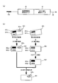
- FIG. 1 is a schematic diagram for explaining an outline of processing performed in the fluorescence / phosphorescence detection unit according to the present embodiment.
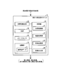
- FIG. 2 is a block diagram showing a schematic configuration of the fluorescence / phosphorescence detection unit.
- FIG. 3 is a schematic diagram for explaining a coefficient table used for gain correction of a phosphorescent image.
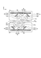
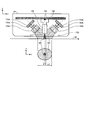
- FIG. 4 is a schematic cross-sectional view showing a schematic structure of the sensor unit.
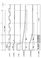
- FIG. 5 is a timing chart for explaining a method of acquiring a fluorescence image and a phosphorescence image of a paper sheet by the fluorescence / phosphorescence detection unit.
- FIG. 1 is a schematic diagram for explaining an outline of processing performed in the fluorescence / phosphorescence detection unit according to the present embodiment.
- FIG. 2 is a block diagram showing a schematic configuration of the fluorescence / phosphorescence detection unit.
- FIG. 3 is a schematic diagram for explaining a coefficient table used for gain correction of
- FIG. 6 is a schematic diagram for explaining the irradiation range of excitation light and the measurement range of image data by the fluorescence / phosphorescence detection unit.
- FIG. 7 is a diagram illustrating the movement of the partial area on the paper sheet corresponding to the irradiation range of the excitation light.
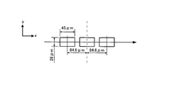
- FIG. 8 is a diagram illustrating the arrangement of the light receiving elements.
- the fluorescence / phosphorescence detection apparatus is used, for example, in a paper sheet processing apparatus that discriminates the type or authenticity of paper sheets and counts the number of sheets.
- a paper sheet authenticity determination device that determines the authenticity of a paper sheet in a paper sheet processing apparatus is based on a feature amount acquired from a visible light image obtained by imaging the paper sheet, and a fluorescence / phosphorescence detection device. The authenticity of the paper sheet is determined based on the detection result of the fluorescence emission and the phosphorescence emission.
- paper that is subject to fluorescence / phosphorescence detection as long as it is a paper that is excited by fluorescence and phosphorescence when irradiated with excitation light in a predetermined wavelength range.
- Examples include coupons, gift certificates, stock certificates, checks, banknotes, and the like.
- FIG. 1 is a schematic diagram for explaining an outline of processing performed in the fluorescence / phosphorescence detection unit 10.
- the fluorescence / phosphorescence detection unit 10 is connected to a paper sheet type discrimination unit 20 and is transported on a transport path by a paper sheet transport unit 30 in the paper sheet processing apparatus.
- the paper sheet 100 passes through the paper sheet type discrimination unit 20 and the fluorescence / phosphorescence detection unit 10.
- a paper sheet authenticity determination unit (not shown) is subjected to a determination result by the paper sheet type determination unit 20, a detection result of fluorescence and phosphorescence by the fluorescence / phosphorescence detection unit 10, a magnetic field and a paper sheet.
- the authenticity of the paper sheet 100 is determined based on the detection result of the thickness of the paper.
- the paper sheet type discriminating unit 20 is configured so that the paper sheet 100 conveyed by the paper sheet conveying unit 30 reaches the detection position of the fluorescence emission and phosphorescence emission in the fluorescence / phosphorescence detection unit 10 before the sheet emission.
- the type of the class 100 is determined.
- the discrimination result by the paper sheet type discrimination unit 20 is input to the fluorescence / phosphorescence detection unit 10.
- the type of the paper sheet 100 is used to specify the type of light emission excited on the paper sheet 100 and the position and size of the partial region on the paper sheet 100 where light emission is excited. Information.
- the denomination information discriminated by the paper sheet type discriminating unit 20 and the information on the front and back sides and the transport direction are input to the fluorescence / phosphorescence detection unit 10 as the type discrimination result.
- the 1A shows a configuration in which the paper sheet type discriminating unit 20 and the fluorescence / phosphorescence detection unit 10 are arranged in order on the transport path, but the fluorescence / phosphorescence detection unit 10 discriminates the paper sheet type.
- the structure contained in the unit 20 may be sufficient.
- the fluorescence / phosphorescence detection unit 10 In the fluorescence / phosphorescence detection unit 10, information such as the type of light emission excited by the paper sheet 100 and the partial region that emits light on the paper sheet 100 is stored in advance in association with the type of the paper sheet 100. Yes. Based on the type information of the paper sheet 100 input from the paper sheet type discriminating unit 20, the fluorescence / phosphorescence detection unit 10 matches the timing when the paper sheet 100 is conveyed through the unit. The timing of turning on and off the light source that irradiates the excitation light toward 100 is controlled, and fluorescence emission and phosphorescence emission excited by the excitation light are imaged.
- FIG. 1B shows an example of an image obtained by imaging fluorescence emission and phosphorescence emission excited by the paper sheet 100 and processing performed on each image.
- the fluorescence / phosphorescence detection unit 10 includes a fluorescence image 201 obtained by imaging fluorescence emitted by the paper sheet 100 and phosphorescence obtained by imaging phosphorescence emitted by the paper sheet 100.
- An image 301 is acquired.
- fluorescence image 201 fluorescence region images 201a to 201c are included in three partial regions where fluorescence emission is excited.
- phosphorescent region images 301a and 301b are included in two partial regions where phosphorescence emission is excited.
- phosphorescence emission is also excited in the same partial region on the paper sheet 100 where fluorescence emission images 201a and 201b are obtained by excitation of fluorescence emission, and phosphorescence region images 301a and 301b are obtained. It shows that. For this reason, the fluorescent region images 201a and 201b on the fluorescent image 201 and the phosphorescent region images 301a and 301b on the phosphorescent image 301 are the same region. On the other hand, in the partial region where the fluorescent region image 201c is obtained, only the fluorescent emission is excited and the phosphorescent emission is not excited. Therefore, the region on the phosphorescent image 301 corresponding to the fluorescent region image 201c of the fluorescent image 201 is phosphorescent. The area image is not obtained.
- the fluorescence / phosphorescence detection unit 10 first corrects the inclination of the image ( A1). Next, the fluorescence / phosphorescence detection unit 10 corrects the gains of the phosphorescence region images 302a and 302b so that the phosphorescence region images 302a and 302b appear clearly on the phosphorescence image 302 whose inclination is corrected (A2). Specifically, the pixel value is converted by multiplying the pixel value of each pixel forming the phosphorescent region images 302a and 302b by a preset coefficient.
- the coefficient is set in advance for each region where phosphorescence emission occurs, and is stored in the fluorescence / phosphorescence detection unit 10 for each type and region of the paper sheet 100.
- the coefficient can be set according to the color of fluorescent light emission or phosphorescent light emission, for example, in addition to being set for each region.
- Each coefficient for correcting the gain of the phosphorescent region images 302a and 302b is obtained by multiplying the pixel value of each pixel forming the phosphorescent region images 302a and 302b with the corresponding fluorescent region images 202a and 202b. Is set to be approximately the same as the pixel value of each pixel forming the. For example, the reciprocal of the phosphorescence emission decay rate or a value corresponding to the reciprocal is set as the coefficient, and different coefficients can be set for the phosphorescent region image 302a and the phosphorescent region image 302b.
- the pixel value of each pixel forming the phosphorescent region image 303a is substantially the same as the pixel value of the corresponding pixel forming the fluorescent region image 202a in the fluorescent image 202. Become. Similarly, the pixel values of the corresponding pixels are substantially the same between the phosphor region image 303b after gain correction and the corresponding fluorescent region image 202b.
- the fluorescence / phosphorescence detection unit 10 finishes the gain correction of the phosphorescence region images 302a and 302b included in the phosphorescence image 302, the phosphorescence image 303 after the gain correction is formed from the pixel value of each pixel forming the fluorescence image 202.
- a difference image is generated by subtracting the pixel value of each pixel (A3).
- the difference image 401 is an image in which the fluorescent region images 202a and 202b corresponding to the phosphorescent region images 303a and 303b of the phosphorescent image 302 are deleted from the fluorescent image 202 and only the fluorescent region image 401c is left.
- the area where both the fluorescence emission and the phosphorescence emission are imaged does not include the partial area image where the emission is imaged, and the area where only the fluorescence emission is imaged and the area where only the phosphorescence emission is imaged Is an image including a partial region image.
- the fluorescence / phosphorescence detection unit 10 performs gain correction using a coefficient set in accordance with the emission intensity of phosphorescence emission for each region where phosphorescence emission is excited in advance. Region images 303a and 303b can be obtained.
- the fluorescence emission state and the phosphorescence emission state change depending on the state of the paper sheet 100 such as dirt or secular change, different images are obtained although the same light emission phenomenon of the same paper sheet 100 is captured. May be obtained. Even in such a case, the fluorescence / phosphorescence detection unit 10 can suppress the influence of the state of the paper sheet 100 by obtaining the difference image 401 from the fluorescence image 202 and the phosphor image 303 after gain correction.
- the authenticity of the paper sheet 100 can be determined using these.
- an image obtained by the fluorescence / phosphorescence detection unit 10 using the true paper sheet 100 is prepared in advance as a template image, and the template image and the image obtained by the fluorescence / phosphorescence detection unit 10 are Can be determined whether the paper sheet 100 is true or false. Further, by using this evaluation result, the authenticity determination of the paper sheet 100 can be performed by the paper sheet type determination unit 20 and the paper sheet authenticity determination unit connected to the fluorescence / phosphorescence detection unit 10. .
- FIG. 2 is a block diagram showing a schematic configuration of the fluorescence / phosphorescence detection unit 10.
- the fluorescence / phosphorescence detection unit 10 obtains the type determination result of the paper sheet 100 from the paper sheet type determination unit 20, and the fluorescent image 201 according to the type of the paper sheet 100.
- 202, phosphorescent images 301 to 303, and a difference image 401 between a fluorescent image and a phosphorescent image are output.
- the image output from the fluorescence / phosphorescence detection unit 10 is input to an external device such as a paper sheet authenticity determination unit.
- the fluorescence / phosphorescence detection unit 10 includes a paper sheet transport unit 30, a light source 40, an image sensor 50, a control unit 60, and a storage unit 70.
- the paper sheet transport unit 30 has a function of transporting the paper sheet 100 through a transport path in the fluorescence / phosphorescence detection unit 10.
- the paper sheet transport unit 30 transports the paper sheet 100 at a high speed, for example, at a speed of 2000 mm / Sec.
- the light source 40 has a function of irradiating light of a predetermined wavelength range onto the paper sheet 100 conveyed on the conveyance path by the paper sheet conveyance unit 30 by a light emitting element such as an LED.
- the light source 40 irradiates ultraviolet light toward the paper sheet 100 by, for example, an ultraviolet LED.
- the aspect which irradiates the light from LED toward the paper sheets 100 directly may be sufficient, and the light from LED is irradiated through a light guide using a light guide. You may be the aspect to do.
- the image sensor 50 has a function of acquiring a fluorescence emission image and a phosphorescence emission image excited by the paper sheet 100.
- the image sensor 50 is formed by a light receiving element such as a photodiode and an RGB color filter. Specifically, for example, a plurality of light receiving elements having light receiving surfaces of 26 ⁇ m ⁇ 45 ⁇ m (main scanning direction ⁇ sub-scanning direction) are arranged in one row in the main scanning direction with an interval of 42.3 ⁇ m between the centers. Three rows are arranged so that the distance between the centers of the rows adjacent to each other in the sub-scanning direction is 84.6 ⁇ m.
- the RGB color filters are R (red) color filters on the first light receiving element row, G (green) color filters on the second light receiving element row, and third light receiving element rows. Install so that the B (blue) color filter is positioned on the line.
- the image sensor 50 can acquire RGB color images and full-color images.
- the paper sheet conveyed by the paper sheet conveyance unit 30 is installed by adjusting the image sensor 50 so that the direction in which the light receiving elements are arranged in one row is perpendicular to the conveyance direction by the paper sheet conveyance unit 30.
- the line data of each RGB color is acquired while scanning the line 100 line by line, and the image data of each color of RGB and the full color image data of the entire surface of the paper sheet 100 can be acquired.
- the storage unit 70 is a non-volatile storage device such as a semiconductor memory or a hard disk, and stores paper sheet data 71 therein. For example, for each type of paper sheet 100, to perform gain correction on information on a partial region where fluorescence emission is excited on the paper sheet 100, information on a partial region where phosphorescence emission is excited, and phosphorescence image 302. The information relating to the coefficient of the image, the information relating to the imaging conditions for obtaining the fluorescent image 201 and the phosphorescent image 301 are stored.
- the control unit 60 includes a light source control unit 61, an image acquisition unit 62, an image processing unit 63, and an image output unit 64.
- the light source control unit 61 controls the light source 40 for acquiring the fluorescent image 201 and the phosphorescent image 301.
- the image acquisition unit 62 has a function of acquiring the fluorescent image 201 and the phosphorescent image 301 of the paper sheet 100 conveyed by the paper sheet conveyance unit 30. Details of a method for acquiring the fluorescent image 201 and the phosphorescent image 301 by the light source control unit 61 and the image acquisition unit 62 will be described later.
- the image processing unit 63 performs processing such as tilt correction of the fluorescent image 201 and the phosphorescent image 301 acquired by the image acquisition unit 62, gain correction of the phosphorescent image 302, and generation of a difference image 401 from the fluorescent image 202 and the phosphorescent image 303. Has the function to perform.
- FIG. 3 is a schematic diagram for explaining a coefficient table used for gain correction of the phosphorescent image 302.
- the paper sheet 100 is divided into regions 1 to n based on the region where fluorescence emission is excited and the region where phosphorescence emission is excited on the paper sheet 100. Divided.
- different coefficients can be set depending on the type and direction of the paper sheet 100 and the areas 1 to n.
- the direction in the coefficient table for example, a banknote whose portrait is included on the surface, the paper sheet 100 shown in FIG. 3A shows the surface, the portrait is upright, and the head is in the upward direction.
- the image processing unit 63 refers to the coefficient table included in the sheet data 71 of the storage unit 70.
- the image processing unit 63 corrects the gain by multiplying the pixel value of each pixel by a coefficient ⁇ 11 in the region 1, for example, using the type 1 and A direction coefficient, In region 2, the gain is corrected by multiplying the pixel value of each pixel by a coefficient ⁇ 12.
- the image output unit 64 has a function of outputting at least one of the fluorescence images 201 and 202, the phosphorescence images 301 to 303, and the difference image 401 obtained by the fluorescence / phosphorescence detection unit 10 to an external device. Which image is to be output is set in advance according to the type of the paper sheet 100 and the external device that is the output destination, and the image output unit 64 selects and outputs an image based on this setting. For example, the image output unit 64 outputs the difference image 401 toward the paper sheet authenticity determination unit.
- the paper sheet authenticity determination unit includes the image input from the fluorescence / phosphorescence detection unit 10 and the information related to the type of the paper sheet 100 input from the paper sheet type determination unit 20. Data such as a visible light image, magnetic characteristics, and thickness is acquired, and the authenticity of the paper sheet 100 is determined by comprehensively determining the acquired data.
- FIG. 4 is a schematic cross-sectional view showing a schematic structure of the sensor units 151 and 251, and shows a cross-sectional shape of the sensor units 151 and 251 when viewed from the side.
- the positive direction of the X axis in FIG. 4 is the conveyance direction of the paper sheet 100 by the paper sheet conveyance unit 30.
- the fluorescence / phosphorescence detection unit 10 includes two sensor units 151 and 251 that are opposed to each other vertically so as to sandwich a conveyance path through which the paper sheet 100 is conveyed by the paper sheet conveyance unit 30.
- the upper sensor unit 151 will be described.
- the upper sensor unit 151 has a structure in which a transparent member 152 is fitted in a part of the sensor case, and the light source 40, the image sensor 50, and the like are accommodated in the sensor case.
- the light source 40 includes an LED 153a on the left substrate 163a and an LED 153b on the right substrate 163b.
- the LEDs 153a and 153b are ultraviolet LEDs that emit ultraviolet light.
- Visible cut filters 154a and 154b are installed in the direction of irradiating ultraviolet light from the LEDs 153a and 153b toward the paper sheet 100, and visible light components having a wavelength of 400 nm or more are cut from the light emitted by the LEDs 153a and 153b.
- the ultraviolet light irradiated from the two LEDs 153a and 153b and transmitted through the visible cut filters 154a and 154b passes through the transparent member 152 and is irradiated toward the paper sheet 100 conveyed by the paper sheet conveying unit 30.
- FIG. 4 only one set of LEDs 153 a and 153 b is shown, but the LEDs forming the light source 40 are arranged in the image sensor 50 so as to irradiate the entire imaging target area on the paper sheet 100 with sufficient light. Are arranged side by side in a direction (Y-axis direction) perpendicular to the transport direction (X-axis direction).
- the image sensor 50 includes a light receiving element 155 such as a photodiode fixed to the substrate 165 and an RGB color filter for obtaining color data by each light receiving element 155.
- a rod lens array (light receiving lens) 156 that receives light from the paper sheet 100 is provided on the optical path from the paper sheet transport unit 30 to the light receiving element 155.
- the plurality of light receiving elements 155 forming the image sensor 50 are arranged side by side in a direction perpendicular to the transport direction so that the entire upper surface of the paper sheet 100 transported by the paper sheet transport unit 30 can be imaged.
- a rod lens array 156 is formed by rod lenses provided corresponding to the light receiving elements 155 for each number. Each rod lens is vapor-deposited with an ultraviolet cut filter so that an ultraviolet light component of 400 nm or less is cut before the light from the paper sheet 100 reaches the light receiving element 155.
- the light reflected by the upper surface of the paper sheet 100 conveyed by the paper sheet conveying unit 30 and transmitted through the transparent member 152 is incident from the lower surface of the rod lens array 156, received by the light receiving element 155, and then the upper sensor.
- the unit 151 can image the entire upper surface of the paper sheet 100 conveyed by the paper sheet conveying unit 30.
- the lower sensor unit 251 includes, as the light source 40, the LED 253a on the right substrate 263a and the LED 253b on the left substrate 263b as in the upper sensor unit 151.
- Each LED 253a, 253b is an ultraviolet LED that emits ultraviolet light.
- Visible cut filters 254a and 254b are installed in the direction of irradiating ultraviolet light from the LEDs 253a and 253b toward the paper sheet 100, and visible light components having a wavelength of 400 nm or more are cut from the light emitted from the LEDs 253a and 253b. Thereafter, the light is irradiated toward the paper sheet 100 which is transmitted through the transparent member 252 and conveyed by the paper sheet conveyance unit 30.
- LEDs 253 a and 253 b are arranged in the image sensor 50 so as to irradiate the entire imaging target area on the paper sheet 100 with sufficient light.
- Y-axis direction perpendicular to the transport direction (X-axis direction).
- the lower sensor unit 251 includes, as the image sensor 50, a light receiving element 255 such as a photodiode fixed to the substrate 265, and an RGB color filter for acquiring color data by each light receiving element 255. .
- a rod lens array (light receiving lens) 256 is provided on the optical path from the paper sheet transport unit 30 to the light receiving element 255.
- the plurality of light receiving elements 255 forming the image sensor 50 are arranged side by side in a direction perpendicular to the transport direction so that the entire back surface of the paper sheet 100 transported by the paper sheet transport unit 30 can be imaged.
- a rod lens array 256 is formed by rod lenses provided corresponding to the light receiving elements 255 for each number. Each rod lens is vapor-deposited with an ultraviolet cut filter so that an ultraviolet light component of 400 nm or less is cut before the light from the paper sheet 100 reaches the light receiving element 255.
- the light reflected by the lower surface of the paper sheet 100 conveyed by the paper sheet conveying unit 30 and transmitted through the transparent member 252 is incident from the upper surface of the rod lens array 256, received by the light receiving element 255, and is received on the lower side.
- the sensor unit 251 can image the entire lower surface of the paper sheet 100 conveyed by the paper sheet conveying unit 30.
- the sensor cases of the upper and lower sensor units 151 and 251 are provided so as to be vertically symmetrical with respect to the transport path because the mounting base that supports each sensor above and below the transport path is provided. This is because it is shared with other sensors.
- a sensor unit having another function such as an ultrasonic sensor can be mounted so as to face each other. Costs related to the unit mounting base can be reduced.
- the two sensor units 151 and 251 are opposed to each other up and down across the transport path so that the sensor cases are at the same position in the X-axis direction.
- the rod lens array 156 and the light receiving element 155 in the sensor unit 151 installed on the upper side of the transport path, and the rod lens array 256 and the light receiving element 255 in the sensor unit 251 installed on the lower side of the transport path are in the transport direction. It is arranged at a position shifted in the (X-axis direction).
- the upper sensor unit 151 can image the entire upper surface of the paper sheet 100 without being affected by the light emitted from the lower sensor unit 251 toward the lower surface of the paper sheet 100.
- the lower sensor unit 251 can image the entire lower surface of the paper sheet 100 without being affected by light irradiated from the upper sensor unit 151 toward the upper surface of the paper sheet 100.
- FIG. 5 is a timing chart for explaining a method of acquiring a fluorescence image and a phosphorescence image of the paper sheet 100 by the fluorescence / phosphorescence detection unit 10.
- the method for acquiring the fluorescence image and the phosphorescence image is the same between the upper sensor unit 151 and the lower sensor unit 251 of the fluorescence / phosphorescence detection unit 10, and therefore, the upper sensor unit 151 will be described below as an example. I will do it.
- the paper sheet 100 is transported by the paper sheet transport unit 30 at a transport speed of 2000 mm / Sec.
- FIG. 5 shows a time axis
- FIG. 5A shows a clock signal (MCLK) used for the operation of each part of the fluorescence / phosphorescence detection unit 10.
- FIG. 5B shows the irradiation timing of the ultraviolet light emitted from the light source 40
- FIGS. 5C to 5E show the fluorescence emission excited on the paper sheet 100 by the ultraviolet light emitted from the light source 40.
- FIG. Examples of phosphorescence are also shown.
- FIG. 5F shows the acquisition timing of line data for forming a fluorescent image and line data for forming a phosphorescent image. The time during which the paper sheet 100 is transported at a distance of 1.5 mm is one period, and during this one period shown in FIG. 5, line data for one line of fluorescent image and line data for one line of phosphorescent image are acquired. Is done.
- the light source control unit 61 performs a partial region (fluorescence region) in which fluorescence emission is excited on the paper sheet 100 or phosphorescent light emission based on the transport timing of the paper sheet 100 by the paper sheet transport unit 30.
- the light source 40 is turned off ("OFF" in FIG. 5B).
- the timing at which the fluorescent region and the phosphorescent region reach the measurement range of the image sensor 50 is determined based on the paper sheet data 71 in the storage unit 70 based on the type determination result of the paper sheet 100 input to the fluorescence / phosphorescence detection unit 10. Is calculated based on the information related to the fluorescent region and the phosphorescent region on the paper sheet 100 and the information related to the transport timing by the paper sheet transport unit 30 obtained with reference to FIG.
- the type (wavelength range) of light emitted from the light source 40, the emission intensity at the time of irradiation, the timing for turning off the light source 40, and the like are set in advance according to the type of the paper sheet 100, and the paper sheet data 71 Since it is memorize
- FIG. 5C shows an example in which the paper sheet 100 includes a fluorescent region, and the vertical axis indicates the emission intensity of fluorescent light excited in the fluorescent region.
- FIG. 5 (d) shows an example in which the paper sheet 100 includes a fluorescent region and a phosphorescent region, and the vertical axis shows the emission intensity of the fluorescent emission and the phosphorescent emission.
- Phosphorescence emission unlike fluorescence emission, emits light for a while while decreasing the emission intensity after the emission intensity gradually increases and saturates after the excitation light irradiation starts, and after the excitation light irradiation is stopped. Continue to gradually decay and disappear.
- FIG. 5D similarly to FIG. 5C, in
- FIG. 5E shows an example different from FIG. 5D in which the paper sheet 100 includes a fluorescent region and a phosphorescent region.
- the vertical axis shows the emission intensity of fluorescence and phosphorescence.
- the emission intensity of phosphorescence emission and the time until the phosphorescence emission decays and disappears differ depending on the type of ink that emits phosphorescence, that is, the type of phosphorescent material.
- FIG. 5E similarly to FIG. 5C, in the fluorescent region on the paper sheet 100, the fluorescence emission is excited at the timing
- the image acquisition unit 62 acquires line data for forming a fluorescent region image and line data for forming a phosphorescent region image at the timing shown in FIG.
- the image sensor 50 acquires line data for one line forming a fluorescent region image.
- the light source 40 is controlled to be turned on and off at the first clock, and line data forming a fluorescent region image is acquired.
- Line data for forming a phosphorescent area image is acquired at the second clock, but thereafter, light source control and line data acquisition are not performed during the period from the third clock to the sixth clock.
- the fluorescence / phosphorescence detection unit 10 that refers to the paper sheet data 71 in the storage unit 70 based on the paper sheet 100 type determination result input from the paper sheet type determination unit 20 performs fluorescence on the paper sheet 100.
- the position and shape of the region and the phosphorescent region are recognized.
- the image acquisition unit 62 repeats the control shown in FIG. 5 while the fluorescent region passes through the measurement range of the image sensor 50 in accordance with the conveyance timing of the paper sheet conveyance unit 30 to form line data for forming the fluorescent region image. Is acquired line by line.
- the image acquisition unit 62 repeats the control shown in FIG. 5 while the phosphorescent region passes through the measurement range of the image sensor 50, and acquires data for forming the phosphorescent region image line by line.
- the paper sheet 100 conveyed by the paper sheet conveying unit 30 is transferred by the image sensor 50. While passing through the measurement range, both the fluorescent image 201 and the phosphorescent image 301 shown in FIG. 1B can be acquired simultaneously.
- the fluorescence image capturing the fluorescence emission and the phosphorescence emission are captured. Both phosphorescent images can be acquired.
- the fluorescence / phosphorescence detection unit 10 has the sensor units 151 and 251 arranged above and below the conveyance path, the sheet 100 conveyed at high speed by the sheet conveyance unit 30 is a unit. While passing through the inside, a fluorescent image and a phosphorescent image on the surface of the paper sheet 100 and a fluorescent image and a phosphorescent image on the back surface of the paper sheet 100 can be simultaneously acquired.
- the image data related to the fluorescent image and the phosphorescent image can be read out during two clocks shown in FIG. 5, the image data can be read out at a minimum of 0. It can be performed at a pitch of 5 mm.
- the image data can be read at a pitch of 3.0 mm. That is, in the fluorescence / phosphorescence detection unit 10 according to the present embodiment, image data of a fluorescence image and a phosphorescence image can be acquired at a pitch of 0.5 to 3.0 mm. This readout pitch is 250 ⁇ S to 1.5 mS in terms of time.
- the read-out pitch (time) of the image data is 0.5 to 3.0 mm (250 ⁇ S to 1.5 mS), and the afterglow characteristics of the phosphorescent ink used in the paper sheet 100, that is, the phosphorescence emission It is determined in consideration of the light emission characteristics.
- the fluorescence / phosphorescence detection unit 10 has one feature in that it can detect phosphorescence with low emission intensity with high accuracy. Hereinafter, this feature will be described. Since the upper sensor unit 151 and the lower sensor unit 251 of the fluorescence / phosphorescence detection unit 10 have the same configuration, the upper sensor unit 151 will be described below as an example.
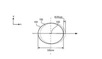
- FIG. 6 is a schematic diagram for explaining the excitation light irradiation range 501 and the image data measurement range 601 by the fluorescence / phosphorescence detection unit 10.
- 6 is a schematic cross-sectional view of the sensor unit 151 viewed from the side, and the lower side is a schematic view of the excitation light irradiation range 501 and the image data measurement range 601 of the sensor unit 151 viewed from above. ing.
- the irradiation range 501 of the ultraviolet light transmitted through the visible cut filters 154a and 154b is set by the paper sheet transport unit 30 as shown in FIG. It has an elliptical shape with a major axis L2 on the conveyance path on which the paper sheet 100 is conveyed.
- the measurement range in which the image data of the paper sheet 100 is acquired from the light receiving element 155 by the image acquisition unit 62 is a range in which the reflected light from the paper sheet 100 is received by the rod lens array 156. Specifically, as shown in FIG.
- the measurement range 601 has an elliptical shape with a major axis L ⁇ b> 1 on the paper sheet 100 conveyed by the paper sheet conveyance unit 30.
- the measurement range 601 has an elliptical shape with a major axis L ⁇ b> 1 on the paper sheet 100 conveyed by the paper sheet conveyance unit 30.
- only one set of structures including the ultraviolet LEDs 153a and 153b and the rod lens array 156 is shown. However, in an actual apparatus, these are arrayed in the Y-axis direction.
- the structure is arranged in a shape.
- the irradiation range 501 and the measurement range 601 shown in FIG. 6 are continuous in the Y-axis direction on the paper surface with a part of the overlap between the adjacent irradiation range 501 and the measurement range 601. . Thereby, data can be acquired from the entire surface of the paper sheet 100 passing through the position of the sensor unit 151.
- the phosphorescent region where phosphorescence emission is excited on the paper sheet 100 moves while acquiring image data related to phosphorescence emission, and passes through a measurement range 601 for acquiring image data.
- the excitation light irradiation range 501 is set to be wide so as not to occur.
- FIG. 7 is a diagram showing the movement of the partial region 101 on the paper sheet 100 corresponding to the excitation light irradiation range 501.
- FIG. 7 is an enlarged view of the light receiving element 155 shown in FIG. 7 and is a diagram for explaining the arrangement of the light receiving elements 155.
- the light receiving element 155 is not shown in FIGS. 4 and 6 due to its small size. However, as described above, the light receiving element 155 is formed by three rows of elements, and as shown in FIG.
- the RGB light receiving elements having a light receiving surface of 26 ⁇ m in the axial direction are arranged in three rows so that the distance between the centers is 84.6 ⁇ m.
- the line data of the phosphorescence region image is acquired after the light source 40 is turned off.
- the paper sheet 100 conveyed at 2000 mm / Sec moves 0.25 mm during one clock period for acquiring line data for one line related to the phosphorescent image.
- the partial area 101 on the paper sheet 100 indicated by the solid line in FIG. 7 moves 0.25 mm in the transport direction to the partial area 102 indicated by the broken line, but the partial area 101 (102) in which phosphorescence emission is excited.
- line data relating to phosphorescence emission is obtained in a region (measurement range 601 in FIG. 6) that is sufficiently small relative to the partial region 101 at the approximate center of the partial region 101 (irradiation range 501 in FIG. 6) irradiated with excitation light. Since it is acquired, phosphorescence emission can be detected with high accuracy without being affected by the movement of the partial region 101.
- Phosphorescence emission can be detected with high accuracy by setting it to 10 times or more the distance (0.25 mm) to which the paper sheet 100 moves.
- a partial area on the paper sheet 100 during data acquisition moves completely from the measurement range 601 for acquiring image data.
- the image data measurement range 601 is set wide so as not to deviate. That is, the partial area on the paper sheet 100 corresponding to the measurement range 601 does not move out of the measurement range 601 during measurement.
- the rod lens array having an opening angle of 20 degrees.
- the partial area under measurement on the paper sheet 100 is completely deviated from the measurement range 601 as the paper sheet 100 is conveyed, and the completely different partial area is detected.
- phosphorescence emission can be detected with high accuracy.
- a fluorescence image, a phosphorescence image, and a difference image between the fluorescence image and the phosphorescence image can be acquired from the paper sheet 100.
- a difference image between a fluorescent image and a phosphorescent image it is possible to obtain an image reflecting the characteristics of phosphorescent light emission by correcting the gain of the phosphorescent image.
- gain correction corresponding to the type of phosphorescence emission can be performed using a coefficient set in advance for each region where phosphorescence emission is excited on the paper sheet 100.
- an irradiation range 501 on the paper sheet 100 irradiated with excitation light from the light source 40 and a measurement range 601 for acquiring line data for forming a phosphorescent image from the paper sheet 100 are provided. Since it is set widely, phosphorescent image data can be acquired with high accuracy from the paper sheet 100 conveyed at high speed.
- the fluorescence / phosphorescence detection unit 10 has two sensor units 151 and 251 installed so as to sandwich the conveyance path from above and below, the fluorescence image and phosphorescence on both sides of the paper sheet 100 conveyed at high speed. Images can be acquired.
- the image sensor 50 is disposed in the transport direction in the sensor units 151 and 251 that are opposed to each other in the vertical direction, the light is emitted from the light sources 40 of the sensor units 151 and 251 that are opposed to each other across the transport path. A fluorescent image and a phosphorescent image can be obtained with high accuracy without being affected by the excitation light.
- the fluorescence / phosphorescence detection apparatus obtains the feature amount relating to the fluorescence emission and phosphorescence emission of the paper sheet as one of the data for determining the authenticity of the paper sheet. As a purpose, it is a useful technique for detecting fluorescence emission and phosphorescence emission with high accuracy.
Abstract
Description
20 紙葉類種類判別ユニット
30 紙葉類搬送部
40 光源
50 イメージセンサ
60 制御部
61 光源制御部
62 画像取得部
63 画像処理部
64 画像出力部
70 記憶部
151、251 センサユニット
152、252 透明部材
153a、153b、253a、253b LED
154a、154b、254a、254b 可視カットフィルタ
155、255 受光素子
156、256 ロッドレンズアレイ
165、265、163a、163b、263a、263b 基板 DESCRIPTION OF
154a, 154b, 254a, 254b
Claims (10)
- 搬送路を搬送される紙葉類の蛍光発光及び燐光発光を検知する蛍光・燐光検知装置であって、
紙葉類に向けて紫外光を照射する光源と、
前記紫外光によって前記紙葉類上で励起された蛍光発光及び燐光発光の画像を撮像可能なイメージセンサと、
前記紙葉類で励起された前記蛍光発光及び前記燐光発光を前記イメージセンサへ導く受光レンズと
を有する2つのセンサユニット
を備え、
前記2つのセンサユニットを前記搬送路を挟んで上下に対向して配置すると共に上下のセンサユニット内での前記受光レンズ及び前記イメージセンサの位置を前記紙葉類の搬送方向にずらして配置する
ことを特徴とする蛍光・燐光検知装置。 A fluorescence / phosphorescence detection device that detects fluorescence emission and phosphorescence emission of paper sheets conveyed in a conveyance path,
A light source that emits ultraviolet light toward the paper sheet;
An image sensor capable of capturing fluorescent and phosphorescent images excited on the paper sheet by the ultraviolet light;
Comprising two sensor units having a light receiving lens for guiding the fluorescence emission and the phosphorescence emission excited by the paper sheet to the image sensor;
The two sensor units are arranged opposite to each other with the conveyance path interposed therebetween, and the positions of the light receiving lens and the image sensor in the upper and lower sensor units are arranged to be shifted in the conveyance direction of the paper sheet. Fluorescence / phosphorescence detection device. - 前記センサユニットは、
前記光源と前記搬送路との間に設けられた可視光カットフィルタと、
前記搬送路と前記イメージセンサとの間に設けられた紫外光カットフィルタと
をさらに備え、
前記イメージセンサはカラー画像を撮像することを特徴とする請求項1に記載の蛍光・燐光検知装置。 The sensor unit is
A visible light cut filter provided between the light source and the transport path;
An ultraviolet light cut filter provided between the conveyance path and the image sensor;
The fluorescence / phosphorescence detection apparatus according to claim 1, wherein the image sensor captures a color image. - 前記センサユニットは、
前記イメージセンサによって燐光発光を撮像した燐光画像のゲインを、予め設定された係数により補正する画像処理部
をさらに備えることを特徴とする請求項1又は2に記載の蛍光・燐光検知装置。 The sensor unit is
The fluorescence / phosphorescence detection apparatus according to claim 1, further comprising an image processing unit that corrects a gain of a phosphorescent image obtained by imaging phosphorescence emission by the image sensor using a preset coefficient. - 前記係数は、燐光発光の減衰率の逆数であることを特徴とする請求項3に記載の蛍光・燐光検知装置。 4. The fluorescence / phosphorescence detection device according to claim 3, wherein the coefficient is a reciprocal of the decay rate of phosphorescence.
- 前記係数は、前記紙葉類の種類及び方向毎に設定されていることを特徴とする請求項3又は4に記載の蛍光・燐光検知装置。 The fluorescence / phosphorescence detection device according to claim 3 or 4, wherein the coefficient is set for each type and direction of the paper sheet.
- 前記係数は、燐光発光が励起される前記紙葉類上の領域毎に設定されていることを特徴とする請求項3~5のいずれか1項に記載の蛍光・燐光検知装置。 The fluorescence / phosphorescence detection device according to any one of claims 3 to 5, wherein the coefficient is set for each region on the paper sheet on which phosphorescence emission is excited.
- 前記係数は、燐光発光の色毎に設定されていることを特徴とする請求項3~6のいずれか1項に記載の蛍光・燐光検知装置。 The fluorescence / phosphorescence detection device according to any one of claims 3 to 6, wherein the coefficient is set for each phosphorescent color.
- 前記画像処理部は、ゲイン補正後の燐光画像と前記イメージセンサによって蛍光発光を撮像した蛍光画像との差分画像を生成することを特徴とする請求項3~7のいずれか1項に記載の蛍光・燐光検知装置。 The fluorescence according to any one of claims 3 to 7, wherein the image processing unit generates a differential image between a phosphor image after gain correction and a fluorescence image obtained by imaging fluorescence emission by the image sensor.・ Phosphorescence detection device.
- 前記画像処理部は、前記燐光画像のゲイン補正により、蛍光発光及び燐光発光の両方が励起された領域の画像を消去した差分画像を生成することを特徴とする請求項8に記載の蛍光・燐光検知装置。 9. The fluorescence / phosphorescence according to claim 8, wherein the image processing unit generates a difference image by deleting an image of a region where both fluorescence emission and phosphorescence emission are excited by gain correction of the phosphorescence image. Detection device.
- 前記イメージセンサは0.5~3.0mmの間のピッチで蛍光発光及び燐光発光の画像データを取得可能であることを特徴とする請求項1~9のいずれか1項に記載の蛍光・燐光検知装置。 10. The fluorescence / phosphorescence according to claim 1, wherein the image sensor is capable of acquiring fluorescence and phosphorescence image data at a pitch of 0.5 to 3.0 mm. Detection device.
Priority Applications (3)
| Application Number | Priority Date | Filing Date | Title |
|---|---|---|---|
| CN201580024729.5A CN106463010A (en) | 2014-05-22 | 2015-05-19 | Fluorescence/phosphorescence detection device |
| US15/313,120 US9841379B2 (en) | 2014-05-22 | 2015-05-19 | Fluorescence and phosphorescence detecting apparatus |
| EP15795501.4A EP3147873B1 (en) | 2014-05-22 | 2015-05-19 | Fluorescence/phosphorescence detection device |
Applications Claiming Priority (2)
| Application Number | Priority Date | Filing Date | Title |
|---|---|---|---|
| JP2014-105859 | 2014-05-22 | ||
| JP2014105859A JP6288709B2 (en) | 2014-05-22 | 2014-05-22 | Fluorescence / phosphorescence detector |
Publications (1)
| Publication Number | Publication Date |
|---|---|
| WO2015178384A1 true WO2015178384A1 (en) | 2015-11-26 |
Family
ID=54554052
Family Applications (1)
| Application Number | Title | Priority Date | Filing Date |
|---|---|---|---|
| PCT/JP2015/064354 WO2015178384A1 (en) | 2014-05-22 | 2015-05-19 | Fluorescence/phosphorescence detection device |
Country Status (5)
| Country | Link |
|---|---|
| US (1) | US9841379B2 (en) |
| EP (1) | EP3147873B1 (en) |
| JP (1) | JP6288709B2 (en) |
| CN (1) | CN106463010A (en) |
| WO (1) | WO2015178384A1 (en) |
Cited By (1)
| Publication number | Priority date | Publication date | Assignee | Title |
|---|---|---|---|---|
| WO2024009953A1 (en) * | 2022-07-06 | 2024-01-11 | グローリー株式会社 | Paper sheet identification device, and paper sheet processing device |
Families Citing this family (12)
| Publication number | Priority date | Publication date | Assignee | Title |
|---|---|---|---|---|
| JP6615014B2 (en) * | 2016-03-15 | 2019-12-04 | グローリー株式会社 | Paper sheet identification device and paper sheet identification method |
| EP3605067A4 (en) * | 2017-03-27 | 2021-03-31 | Glory Ltd. | Optical sensor, light detecting device, paper sheet processing device, light detecting method, and phosphorescence detecting device |
| EP3681376A1 (en) * | 2017-09-10 | 2020-07-22 | Smith & Nephew PLC | Systems and methods for inspection of encapsulation and components in sensor equipped wound dressings |
| CN108195802B (en) * | 2017-11-21 | 2020-09-15 | 广州标旗电子科技有限公司 | Diamond luminescence imaging detection method |
| CN108022364B (en) * | 2017-12-19 | 2023-12-26 | 深圳怡化电脑股份有限公司 | Channel device and self-service deposit and withdrawal equipment |
| EP3503049B1 (en) * | 2017-12-22 | 2021-02-24 | CI Tech Sensors AG | Device and method for detecting a machine-readable security feature of a valuable document |
| CN108074317A (en) * | 2018-02-05 | 2018-05-25 | 浙江然鹏电子有限公司 | A kind of currency counting and detecting machine and its control system for examining bank note color |
| JP7185439B2 (en) * | 2018-08-01 | 2022-12-07 | 株式会社ヴィーネックス | Optical line sensor unit |
| JP7262952B2 (en) | 2018-09-19 | 2023-04-24 | 株式会社東芝 | Paper sheet processing device and paper sheet processing method |
| KR101977634B1 (en) * | 2018-09-28 | 2019-08-28 | 주식회사 카스모아이티 | Counterfeit Bill Detection Sensor Module With Diagonal Image Sensors |
| US20200394864A1 (en) * | 2019-05-30 | 2020-12-17 | Kabushiki Kaisha Toshiba | Paper sheet processing device, paper sheet processing method, and fluorescent image correction method |
| CN110379065B (en) * | 2019-06-06 | 2022-06-10 | 深圳市博利凌科技有限公司 | Banknote, ticket discriminating optics, apparatus, device and method |
Citations (3)
| Publication number | Priority date | Publication date | Assignee | Title |
|---|---|---|---|---|
| WO1999009382A1 (en) * | 1997-08-13 | 1999-02-25 | De La Rue International Limited | Detector methods and apparatus |
| JP2012190253A (en) * | 2011-03-10 | 2012-10-04 | Vienex Corp | Optical line sensor device, and discrimination method of valuable paper |
| WO2014061274A1 (en) * | 2012-10-18 | 2014-04-24 | 三菱電機株式会社 | Image sensor and image sensor device |
Family Cites Families (24)
| Publication number | Priority date | Publication date | Assignee | Title |
|---|---|---|---|---|
| US5467406A (en) | 1990-02-05 | 1995-11-14 | Cummins-Allison Corp | Method and apparatus for currency discrimination |
| GB2309299B (en) | 1996-01-16 | 2000-06-07 | Mars Inc | Sensing device |
| JP3892081B2 (en) | 1996-06-17 | 2007-03-14 | グローリー株式会社 | Authenticity judgment method for paper sheets |
| DE19651101A1 (en) * | 1996-12-09 | 1998-06-10 | Giesecke & Devrient Gmbh | Device and method for the detection of fluorescent and phosphorescent light |
| GB9714083D0 (en) | 1997-07-04 | 1997-09-10 | Ncr Int Inc | Document recognition apparatus |
| EP1752932B2 (en) | 2002-12-27 | 2019-10-16 | Japan Cash Machine Co., Ltd. | Optical sensing device for detecting optical features of valuable papers |
| JP4334910B2 (en) * | 2003-05-28 | 2009-09-30 | ローレル精機株式会社 | Banknote image detection device |
| JP4334913B2 (en) | 2003-05-28 | 2009-09-30 | ローレル精機株式会社 | Banknote image detection device |
| JP4334911B2 (en) * | 2003-05-28 | 2009-09-30 | ローレル精機株式会社 | Banknote image detection device |
| JP4874603B2 (en) | 2005-09-06 | 2012-02-15 | 日本電産コパル株式会社 | Identification method and identification apparatus |
| US8401268B1 (en) | 2007-03-09 | 2013-03-19 | Cummins-Allison Corp. | Optical imaging sensor for a document processing device |
| DE102007044878A1 (en) | 2007-09-20 | 2009-04-09 | Giesecke & Devrient Gmbh | Method and device for checking value documents |
| JP4673393B2 (en) * | 2008-06-05 | 2011-04-20 | 日立オムロンターミナルソリューションズ株式会社 | Paper sheet handling apparatus and method |
| JP2010039897A (en) | 2008-08-07 | 2010-02-18 | Toshiba Corp | Light detection device and paper sheet processor |
| US8822954B2 (en) * | 2008-10-23 | 2014-09-02 | Intematix Corporation | Phosphor based authentication system |
| JP5367509B2 (en) * | 2009-08-27 | 2013-12-11 | 株式会社東芝 | Photodetection device and paper sheet processing apparatus provided with the photodetection device |
| CN102610023B (en) | 2010-09-17 | 2014-11-05 | 中国印钞造币总公司 | Optical detection device for identifying counterfeiting of security and detection method thereof |
| DE102010055700A1 (en) | 2010-12-22 | 2012-06-28 | Giesecke & Devrient Gmbh | Device for measuring length of sheet material e.g. banknote, has evaluation device that is adapted to evaluate the sensed signal output by line sensor |
| CN102610025A (en) | 2011-01-20 | 2012-07-25 | 浙江方泰电器有限公司 | 3-CIS (Contact image sensor) image detection system for identifying notes |
| CN102610026A (en) | 2011-01-20 | 2012-07-25 | 浙江方泰电器有限公司 | 2-CIS (Contact image sensor) image detection system |
| JP5486127B2 (en) | 2011-03-31 | 2014-05-07 | 富士通フロンテック株式会社 | Line sensor unit, automatic transaction equipment |
| KR20140030246A (en) * | 2011-06-06 | 2014-03-11 | 시크파 홀딩 에스.에이. | In-line decay-time scanner |
| JP2013083528A (en) * | 2011-10-07 | 2013-05-09 | Vienex Corp | Contact type optical line sensor device and method for identifying valuable page space |
| KR101348868B1 (en) | 2012-02-16 | 2014-01-08 | 주식회사 엘지씨엔에스 | A media sensing apparatus and financial device |
-
2014
- 2014-05-22 JP JP2014105859A patent/JP6288709B2/en active Active
-
2015
- 2015-05-19 EP EP15795501.4A patent/EP3147873B1/en active Active
- 2015-05-19 US US15/313,120 patent/US9841379B2/en active Active
- 2015-05-19 WO PCT/JP2015/064354 patent/WO2015178384A1/en active Application Filing
- 2015-05-19 CN CN201580024729.5A patent/CN106463010A/en active Pending
Patent Citations (3)
| Publication number | Priority date | Publication date | Assignee | Title |
|---|---|---|---|---|
| WO1999009382A1 (en) * | 1997-08-13 | 1999-02-25 | De La Rue International Limited | Detector methods and apparatus |
| JP2012190253A (en) * | 2011-03-10 | 2012-10-04 | Vienex Corp | Optical line sensor device, and discrimination method of valuable paper |
| WO2014061274A1 (en) * | 2012-10-18 | 2014-04-24 | 三菱電機株式会社 | Image sensor and image sensor device |
Cited By (1)
| Publication number | Priority date | Publication date | Assignee | Title |
|---|---|---|---|---|
| WO2024009953A1 (en) * | 2022-07-06 | 2024-01-11 | グローリー株式会社 | Paper sheet identification device, and paper sheet processing device |
Also Published As
| Publication number | Publication date |
|---|---|
| US20170153184A1 (en) | 2017-06-01 |
| JP2015222463A (en) | 2015-12-10 |
| US9841379B2 (en) | 2017-12-12 |
| EP3147873B1 (en) | 2022-09-28 |
| CN106463010A (en) | 2017-02-22 |
| EP3147873A1 (en) | 2017-03-29 |
| JP6288709B2 (en) | 2018-03-07 |
| EP3147873A4 (en) | 2018-01-24 |
Similar Documents
| Publication | Publication Date | Title |
|---|---|---|
| JP6288709B2 (en) | Fluorescence / phosphorescence detector | |
| JP5367509B2 (en) | Photodetection device and paper sheet processing apparatus provided with the photodetection device | |
| JP6633268B2 (en) | Sensor module and paper sheet processing device | |
| JP6474633B2 (en) | Fluorescence phosphorescence detection apparatus, fluorescence phosphorescence detection method, and paper sheet processing apparatus | |
| WO2014097489A1 (en) | Spectral sensor | |
| JP4703403B2 (en) | Inspection device | |
| WO2015159438A1 (en) | Paper-sheet authenticity determination device and paper-sheet authenticity determination method | |
| EP2506224B1 (en) | Subject discriminating apparatus and coin discriminating apparatus | |
| JP2013020540A (en) | Paper sheet identification device and paper sheet identification method | |
| JP7262952B2 (en) | Paper sheet processing device and paper sheet processing method | |
| WO2019035376A1 (en) | Fluorescence/phosphorescence detection device and fluorescence/phosphorescence detection method | |
| JP2011118457A (en) | Optical detection device and paper sheet processing device including the same | |
| WO2021193465A1 (en) | Optical sensor and paper sheet identifying device | |
| JP7111494B2 (en) | Light detection sensor, light detection device, sheet processing device, and light detection method | |
| JP2009047568A (en) | Printing quality inspection apparatus | |
| US20220277607A1 (en) | Method and device for examining value documents | |
| JP2008299639A (en) | Paper sheet discriminating device | |
| JP5216275B2 (en) | Print quality inspection device | |
| WO2019082251A1 (en) | Optical sensor, optical sensor module, and paper processing device | |
| JPWO2019188096A1 (en) | Photodetector, photodetector, and paper leaf processing device | |
| US20220092904A1 (en) | Fluorescence/phosphorescence detection device, paper sheet processing device, and fluorescence/phosphorescence detection method | |
| WO2022210372A1 (en) | Multifeed detection device and multifeed detection method | |
| US20220392289A1 (en) | Optical sensor, paper sheet identification device, and paper sheet processing device | |
| JP2010033176A (en) | Detection device for fluorescence/afterglow, and paper sheet processing unit | |
| JP2007132864A (en) | Surface inspection device |
Legal Events
| Date | Code | Title | Description |
|---|---|---|---|
| 121 | Ep: the epo has been informed by wipo that ep was designated in this application |
Ref document number: 15795501 Country of ref document: EP Kind code of ref document: A1 |
|
| REEP | Request for entry into the european phase |
Ref document number: 2015795501 Country of ref document: EP |
|
| WWE | Wipo information: entry into national phase |
Ref document number: 2015795501 Country of ref document: EP |
|
| NENP | Non-entry into the national phase |
Ref country code: DE |
|
| WWE | Wipo information: entry into national phase |
Ref document number: 15313120 Country of ref document: US Ref document number: IDP00201607962 Country of ref document: ID |