WO2015174745A1 - Method for performing random access procedure in mtc device - Google Patents
Method for performing random access procedure in mtc device Download PDFInfo
- Publication number
- WO2015174745A1 WO2015174745A1 PCT/KR2015/004821 KR2015004821W WO2015174745A1 WO 2015174745 A1 WO2015174745 A1 WO 2015174745A1 KR 2015004821 W KR2015004821 W KR 2015004821W WO 2015174745 A1 WO2015174745 A1 WO 2015174745A1
- Authority
- WO
- WIPO (PCT)
- Prior art keywords
- random access
- value
- radio frame
- mtc device
- access preamble
- Prior art date
Links
Images


Classifications
-
- H—ELECTRICITY
- H04—ELECTRIC COMMUNICATION TECHNIQUE
- H04W—WIRELESS COMMUNICATION NETWORKS
- H04W74/00—Wireless channel access, e.g. scheduled or random access
- H04W74/08—Non-scheduled or contention based access, e.g. random access, ALOHA, CSMA [Carrier Sense Multiple Access]
Definitions
- the present invention relates to wireless communication, and more particularly, to Machine Type Communication (MTC).
- MTC Machine Type Communication
- 3GPP LTE long term evolution
- UMTS Universal Mobile Telecommunications System
- 3GPP LTE uses orthogonal frequency division multiple access (OFDMA) in downlink and single carrier-frequency division multiple access (SC-FDMA) in uplink.
- OFDMA orthogonal frequency division multiple access
- SC-FDMA single carrier-frequency division multiple access
- MIMO multiple input multiple output
- LTE-A 3GPP LTE-Advanced
- MTC machine type communication
- MTC devices may exist individually for each service and use, a huge number of MTC devices may be located in the coverage of the base station.
- a method of performing a random access procedure in a machine type communication (MTC) device includes determining, when the random access procedure is triggered, the MTC device based on its type and the type of service that triggered the random access procedure; Determining a tolerance factor Tf based on the maximum delay tolerance T value; Selecting a radio frame to transmit a random access preamble based on the tolerance factor Tf; The method may include transmitting a random access preamble on the selected radio frame.
- MTC machine type communication
- the method may further comprise obtaining a network load interworking N value.
- the tolerance factor Tf may be determined based on the maximum delay tolerance T value and the network load interworking N value.
- the radio frame may be determined in consideration of a UEID indicating an identifier of the MTC device, the allowance factor Tf, and a radio frame number (SFN).
- the method includes calculating a random wait time Wdt when the transmission of the random access preamble is not successful; After waiting for the calculated random waiting time Wdt, the method may further include transmitting a random access preamble.
- the transmitting of the random access preamble includes: if the transmission of the random access preamble is not successful, waiting for a backoff time;
- the method may include waiting for the random waiting time Wdt.
- a machine type communication (MTC) device performing a random access procedure.
- MTC machine type communication
- the MTC device determines a maximum delay tolerance T value based on its type and the type of service that triggered the random access procedure, and based on the maximum delay tolerance T value.
- a processor that determines a tolerance factor Tf and then selects a radio frame to transmit a random access preamble based on the tolerance factor Tf; It may include a transceiver for transmitting a random access preamble on the selected radio frame.
- FIG. 1 shows a wireless communication system to which the present invention is applied.
- FIG. 2 is a block diagram illustrating a radio protocol architecture for a user plane.
- FIG. 3 is a block diagram illustrating a radio protocol structure for a control plane.
- FIG. 4 illustrates an operation of a UE and a base station in a contention based random access procedure.
- FIG. 5 illustrates an operation of a UE and a base station in a non-contention based random access procedure.
- MTC 6 illustrates an example of machine type communication (MTC).
- FIG. 7 is a flowchart illustrating a method according to one disclosure of the present specification.
- FIG. 8 is a flowchart illustrating a method according to another disclosure of the present specification.
- FIG. 10 is a block diagram illustrating a wireless communication system in which an embodiment of the present invention is implemented.
- first and second may be used to describe various components, but the components should not be limited by the terms. The terms are used only for the purpose of distinguishing one component from another.
- first component may be referred to as the second component, and similarly, the second component may also be referred to as the first component.
- the terminal may include a user equipment (UE), a mobile equipment (ME), a mobile station (MS), a user terminal (UT), a subscriber station (SS), a wireless device (Wireless Device), It may be called a handheld device or an access terminal (AT).
- the terminal may be a portable device having a communication function such as a mobile phone, a PDA, a smart phone, a wireless modem, a laptop, or the like, or a non-portable device such as a PC or a vehicle-mounted device.
- FIG. 1 shows a wireless communication system to which the present invention is applied.
- E-UTRAN Evolved-UMTS Terrestrial Radio Access Network
- LTE Long Term Evolution
- the E-UTRAN includes a base station (BS) 20 that provides a control plane and a user plane to a user equipment (UE) 10.
- the UE 10 may be fixed or mobile and may have other terms such as terminal, user terminal (UT), mobile station (MS), subscriber station (SS), mobile terminal (MT), and wireless device (Wireless Device).
- the base station 20 refers to a fixed station communicating with the UE 10, and may be referred to in other terms such as an evolved-NodeB (eNB), a base transceiver system (BTS), an access point, and the like.
- eNB evolved-NodeB
- BTS base transceiver system
- access point and the like.
- the base stations 20 may be connected to each other through an X2 interface.
- the base station 20 is connected to a Serving Gateway (S-GW) through an MME (Mobility Management Entity) and an S1-U through an Evolved Packet Core (EPC) 30, more specifically, an S1-MME through an S1 interface.
- S-GW Serving Gateway
- MME Mobility Management Entity
- EPC Evolved Packet Core
- EPC 30 is composed of MME, S-GW and P-GW (Packet Data Network-Gateway).
- the MME has information about the UE's access information or the UE's capability, and this information is mainly used for mobility management of the UE.
- S-GW is a gateway having an E-UTRAN as an endpoint
- P-GW is a gateway having a PDN as an endpoint.
- Layers of the Radio Interface Protocol between the UE and the network are based on the lower three layers of the Open System Interconnection (OSI) reference model, which are well known in communication systems.
- L2 second layer
- L3 third layer
- the RRC Radio Resource Control
- the RRC layer located in the third layer plays a role of controlling radio resources between the UE and the network.
- the RRC layer exchanges RRC messages between the UE and the base station.
- FIG. 2 is a block diagram illustrating a radio protocol architecture for a user plane.
- 3 is a block diagram illustrating a radio protocol structure for a control plane.
- the data plane is a protocol stack for user data transmission
- the control plane is a protocol stack for control signal transmission.
- a physical layer (PHY) layer provides an information transfer service to a higher layer using a physical channel.
- the physical layer is connected to a medium access control (MAC) layer, which is an upper layer, through a transport channel. Data is moved between the MAC layer and the physical layer through the transport channel. Transport channels are classified according to how and with what characteristics data is transmitted over the air interface.
- MAC medium access control
- the physical channel may be modulated by an orthogonal frequency division multiplexing (OFDM) scheme and utilizes time and frequency as radio resources.
- OFDM orthogonal frequency division multiplexing
- the functions of the MAC layer include mapping between logical channels and transport channels and multiplexing / demultiplexing into transport blocks provided as physical channels on transport channels of MAC service data units (SDUs) belonging to the logical channels.
- the MAC layer provides a service to a Radio Link Control (RLC) layer through a logical channel.
- RLC Radio Link Control
- RLC layer Functions of the RLC layer include concatenation, segmentation, and reassembly of RLC SDUs.
- QoS Quality of Service
- the RLC layer has a transparent mode (TM), an unacknowledged mode (UM), and an acknowledged mode (Acknowledged Mode).
- TM transparent mode
- UM unacknowledged mode
- Acknowledged Mode acknowledged mode
- AM Three modes of operation (AM).
- AM RLC provides error correction through an automatic repeat request (ARQ).
- PDCP Packet Data Convergence Protocol
- Functions of the Packet Data Convergence Protocol (PDCP) layer in the user plane include delivery of user data, header compression, and ciphering.
- the functionality of the Packet Data Convergence Protocol (PDCP) layer in the user plane includes the transfer of control plane data and encryption / integrity protection.
- the RRC (Radio Resource Control) layer is defined only in the control plane.
- the RRC layer is responsible for the control of logical channels, transport channels, and physical channels in connection with configuration, re-configuration, and release of radio bearers.
- RB refers to a logical path provided by the first layer (PHY layer) and the second layer (MAC layer, RLC layer, PDCP layer) for data transmission between the user equipment (UE) and the network.
- the establishment of the RB means a process of defining characteristics of a radio protocol layer and a channel to provide a specific service, and setting each specific parameter and operation method.
- RB can be further divided into SRB (Signaling RB) and DRB (Data RB).
- SRB is used as a path for transmitting RRC messages in the control plane
- DRB is used as a path for transmitting user data in the user plane.
- the UE If an RRC connection is established between the RRC layer of the UE (UE) and the RRC layer of the E-UTRAN, the UE is in an RRC connected state (or referred to as RRC connected mode). In this case, it is in an RRC idle state (or RRC idle mode).
- Downlink transmission channels for transmitting data from the network to the UE include a broadcast channel (BCH) for transmitting system information and a downlink shared channel (SCH) for transmitting user traffic or control messages.
- Traffic or control messages of a downlink multicast or broadcast service may be transmitted through a downlink SCH or may be transmitted through a separate downlink multicast channel (MCH).
- uplink transport channels for transmitting data from a UE to a network include a random access channel (RACH) for transmitting an initial control message and an uplink shared channel (SCH) for transmitting user traffic or control messages.
- RACH random access channel
- SCH uplink shared channel
- BCCH broadcast control channel
- PCCH paging control channel
- CCCH common control channel
- MCCH multicast control channel
- MTCH multicast traffic
- the physical channel is composed of several OFDM symbols in the time domain and several sub-carriers in the frequency domain.
- One sub-frame consists of a plurality of OFDM symbols in the time domain.
- the RB is a resource allocation unit and includes a plurality of OFDM symbols and a plurality of subcarriers.
- each subframe may use specific subcarriers of specific OFDM symbols (eg, the first OFDM symbol) of the corresponding subframe for the physical downlink control channel (PDCCH), that is, the L1 / L2 control channel.
- Transmission Time Interval is a unit time of subframe transmission.
- RRC state refers to whether or not the RRC layer of the UE is in logical connection with the RRC layer of the E-UTRAN.If connected, the RRC connected state, if not connected, is RRC idle. This is called the RRC idle state. Since the UE in the RRC connected state has an RRC connection, the E-UTRAN can grasp the existence of the corresponding UE in a cell unit, and thus can effectively control the UE. On the other hand, the UE in the RRC idle state cannot be identified by the E-UTRAN, and is managed by the core netwrok (CN) in units of a tracking area, which is a larger area than a cell. That is, the UE in the RRC idle state is identified only in a large area unit, and must move to the RRC connected state in order to receive a normal mobile communication service such as voice or data.
- CN core netwrok
- the UE When a user first powers up a UE, the UE first searches for an appropriate cell and then stays in an RRC idle state in that cell. When the UE in the RRC idle state needs to establish an RRC connection, the UE establishes an RRC connection with the E-UTRAN through an RRC connection procedure and transitions to the RRC connected state. There are several cases where a UE in RRC idle state needs to establish an RRC connection. For example, an upstream data transmission is necessary due to a user's call attempt, or a paging message is sent from E-UTRAN. If received, a response message may be sent.
- the non-access stratum (NAS) layer located above the RRC layer performs functions such as session management and mobility management.
- EMM-REGISTERED EPS Mobility Management-REGISTERED
- EMM-DEREGISTERED EMM-DEREGISTERED
- the initial UE is in an EMM-DEREGISTERED state, and the UE performs a process of registering with the corresponding network through an initial attach procedure in order to access the network. If the attach procedure is successfully performed, the UE and the MME enter the EMM REGISTERED state.
- an EPS Connection Management (ECM) -IDLE state In order to manage a signaling connection between the UE and the EPC, two states are defined, an EPS Connection Management (ECM) -IDLE state and an ECM-CONNECTED state, and these two states apply to the UE and the MME.
- ECM EPS Connection Management
- ECM-IDLE state makes an RRC connection with the E-UTRAN
- the UE is in the ECM-CONNECTED state.
- the MME in the ECM-IDLE state becomes the ECM-CONNECTED state when it establishes an S1 connection with the E-UTRAN.
- the E-UTRAN does not have context information of the UE.
- the UE in the ECM-IDLE state performs UE-based mobility related procedures such as cell selection procedure or cell reselection procedure without the need of a network command.
- the cell selection procedure means that the UE selects a cell to access a network service.
- the cell reselection procedure means finding the best cell that can be configured as a serving cell.
- the UE when the UE is in the ECM-CONNECTED state, the mobility of the UE is managed by the command of the network.
- the UE In the ECM-IDLE state, if the location of the UE is different from the location known by the network, the UE informs the network of the location of the UE through a tracking area update procedure.
- the system information includes essential information that the UE needs to know in order to connect to the base station. Therefore, the UE must receive all system information before accessing the base station, and must always have the latest system information. And since the system information is information that every UE in a cell should know, the base station periodically transmits the system information.
- the system information includes a master information block (MIB) and a scheduling block (SB). It is divided into SIB (System Information Block).
- MIB master information block
- SB scheduling block
- the MIB allows the UE to know the physical configuration of the cell, such as bandwidth.
- SB informs transmission information of SIBs, for example, a transmission period.
- SIB is a collection of related system information. For example, some SIBs contain only information of neighboring cells, and some SIBs contain only information of an uplink radio channel used by the UE.
- the base station transmits a call message to inform the UE whether to change the system information.
- the call message includes a system information change indicator.
- the UE receives the call message according to the paging DRX, and if the call message includes the system information change indicator, receives the system information transmitted through the logical channel BCCH.
- a base station allocates a designated random access preamble to a specific UE, and the UE provides a non-competitive random access procedure for performing a random access procedure with the random access preamble.
- a contention based random access procedure in which a UE selects one randomly within a specific set and a random access preamble allocated by a base station only to a specific UE are used.
- the non- contention based random access procedure may be used only when requested by the handover process or the command of the base station described above.
- FIG. 4 illustrates an operation of a UE and a base station in a contention based random access procedure.
- a UE selects one random access preamble randomly from a set of random access preambles indicated by system information or a handover command, and transmits the random access preamble. Select to send.
- the UE After transmitting the random access preamble as described above, the UE attempts to receive its random access response within the random access response reception window indicated by the base station through system information or a handover command.
- the random access response information is transmitted in the form of MAC PDU
- the MAC PDU is transmitted in PDSCH.
- the PDCCH is also delivered to the UE to properly receive the information delivered to the PDSCH. That is, the PDCCH includes information of a UE that should receive the PDSCH, frequency and time information of radio resources of the PDSCH, a transmission format of the PDSCH, and the like.
- the UE After the UE succeeds in receiving the PDCCH coming to it, it properly receives the random access response sent to the PDSCH according to the information of the PDCCH.
- the random access response includes a random access preamble identifier (ID), a UL Grant (uplink radio resource), a Temporary C-RNTI (temporary cell identifier), and a Time Alignment Command.
- ID random access preamble identifier
- UL Grant uplink radio resource
- Temporary C-RNTI temporary cell identifier
- Time Alignment Command The reason why the random access preamble discriminator is needed is that since one random access response may include random access response information for one or more UEs, indicating to which UE the UL Grant, Temporary C-RNTI and the TAC are valid. It is for.
- the random access preamble identifier corresponds to the random access preamble selected by the user in step 1.
- the UE When the UE receives a valid random access response to the UE, it processes each of the information included in the random access response. That is, the UE applies the TAC and stores the Temporary C-RNTI.
- the UE applies the TAC and stores the Temporary C-RNTI.
- the UL Grant data stored in the buffer of the UE or newly generated data is transmitted to the base station.
- an identifier of the UE must be included essentially. This is because, in the contention-based random access procedure, it is not possible to determine which UEs perform the random access procedure in the base station, since the UE needs to be identified for future collision resolution.
- there are two methods for including the identifier of the UE there are two methods for including the identifier of the UE.
- the UE transmits its cell identifier through the UL Grant.
- the UE transmits its own unique identifier (eg, S-TMSI or Random Id). In general, the unique identifier is longer than the cell identifier. If the UE has transmitted data through the UL Grant, the UE starts a contention resolution timer.
- the UE After the UE transmits data including its identifier through the UL Grant included in the random access response, it waits for an indication of the base station to resolve the collision. That is, it attempts to receive a PDCCH to receive a specific message.
- the UE determines that the random access procedure has been normally performed and ends the random access procedure.
- the PDCCH is received through the temporary cell identifier before the conflict resolution timer expires, the data transmitted by the PDSCH indicated by the PDCCH is checked. If the unique identifier is included in the content of the data, the UE determines that the random access procedure has been normally performed, and terminates the random access procedure.
- FIG. 5 illustrates an operation of a UE and a base station in a non-contention based random access procedure.
- the non- contention-based random access process by receiving the random access response information, it is determined that the random access process is normally performed, and ends the random access process.
- the non-contention based random access procedure may exist firstly in the case of a handover procedure and secondly, in a case requested by a command of a base station.
- the contention-based random access procedure may be performed in both cases.
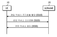
- the UE transmits the preamble to the base station after receiving the random access preamble assigned to itself as the base station.
- step S530 The method of receiving random access response information is the same as in the contention-based random access procedure.
- the reason why collision occurs in the random access process is because the number of random access preambles is basically finite. That is, since the base station cannot grant UE-specific random access preamble to all UEs, the UE randomly selects and transmits one of the common random access preambles. Accordingly, when two or more UEs select and transmit the same random access preamble through the same PRACH resource, the base station determines that one random access preamble is transmitted from one UE. For this reason, the base station transmits a random access response to the UE, and predicts that the random access response will be received by one UE.
- One method is to use a contention resolution timer (hereinafter referred to as a CR timer), and the other is to transmit an identifier of a successful UE to the UEs.
- the former case is used when the UE already has a unique cell identifier (C-RNTI) before the random access procedure. That is, the UE which already has the cell identifier transmits data including its cell identifier to the base station according to the random access response, and operates the collision resolution timer. Then, if the PDCCH information including its cell identifier is received before the conflict resolution timer expires, the UE determines that it has succeeded in the competition, and ends the random access process normally.
- C-RNTI unique cell identifier
- the PDCCH containing the cell identifier is not transmitted before the conflict resolution timer expires, it is determined that it has failed in the race, re-performs the random access procedure, or notifies the upper layer of the failure. Done.
- the latter case of the collision resolution method that is, a method of transmitting an identifier of a successful UE is used when the UE does not have a unique cell identifier before the random access procedure. That is, when the UE itself does not have a cell identifier, the UE transmits data including an identifier higher than the cell identifier (S-TMSI or Random Id) according to UL Grant information included in the random access response, and the UE operates a collision resolution timer.
- S-TMSI or Random Id an identifier higher than the cell identifier
- the UE determines that the random access procedure is successful.
- the conflict resolution timer expires, if the data including its higher identifier is not transmitted to the DL-SCH, the UE determines that the random access procedure has failed.
- MTC 6 illustrates an example of machine type communication (MTC).
- Machine Type Communication is an exchange of information through the base station 200 between MTC devices 100 without human interaction or information through a base station between the MTC device 100 and the MTC server 700.
- MTC Machine Type Communication
- M2M Machine to Machine
- H2H human to human
- the MTC server 700 is an entity that communicates with the MTC device 100.
- the MTC server 700 executes an MTC application and provides an MTC specific service to the MTC device.
- the MTC device 100 is a wireless device that provides MTC communication and may be fixed or mobile.
- the services offered through MTC are different from those in existing human-involved communications, and there are various categories of services such as tracking, metering, payment, medical services, and remote control. exist. More specifically, services provided through the MTC may include meter reading, level measurement, utilization of surveillance cameras, inventory reporting of vending machines, and the like.
- the uniqueness of the MTC device is that the amount of data transmitted is small and the up / down link data transmission and reception occur occasionally. Therefore, it is effective to lower the cost of the MTC device and reduce battery consumption in accordance with such a low data rate.
- Table 1 Type of MTC Device Data Processing Speed Error Rate Requirements Delay sensitivity Smart meter lowness lowness lowness Vehicle management lowness lowness Middle price Point of sale terminal (POS) lowness middle height Live video lowness lowness lowness
- the MTC device does not require a wide range of services, but has a feature of requiring only a small number of special services.
- MTC devices may exist individually for each service and use, a huge number of MTC devices may be located in the coverage of the base station. However, since such a large number of MTC devices are placed in the coverage of the base station, there is a possibility that the quality of H2H communication may be degraded.
- the 3GPP Release 10 standard document considers adding “Delay tolerant access” as the RRC establishment cause value. This allows the network to reject RRC connection requests with an extended wait timer. However, even with this solution, it is not effective when the MTC device continuously attempts random access and transmits an RRC connection request. As a better solution, consider preventing random access attempts if delays are acceptable for the MTC device's access. This solution can be very effective in terms of battery savings.
- smartphones are currently installed with various kinds of applications running in the background. While data by some of the many applications may be delayed, data by some other applications may be very sensitive to delay. However, these are not distinguished and are inefficient.
- a network delivers information for an access class barring (ACB) differently for each UE to block access of a specific UE.
- ACB access class barring
- the disclosures of the present disclosure aim to provide a method of performing access control on a device or a service having a high delay tolerance in order to solve the above problem.
- one disclosure of the present specification is intended to propose a method for preventing a network from being congested by data having a high delay tolerance among data generated by an MTC device (or an M2M device).
- one disclosure of the present specification proposes a method for adding a condition that an MTC device (or M2M device) generating high delay tolerance data can initiate random access.
- FIG. 7 is a flowchart illustrating a method according to one disclosure of the present specification.
- the MTC device selects a maximum delay allowance T value (S103).
- the maximum delay tolerance T value may be any one of 1, 2, 4, 8, 16, 32, 64, 128, 256, 512, and 1024.
- the MTC device may select any one of the maximum delay tolerance T values according to its type and service type. More specifically, if the type of the MTC device can perform various services, one of the maximum delay tolerance T values may be selected according to the type of the service that triggered the current random access procedure.
- the MTC device obtains a load interworking N value broadcast in the network (S105), and checks whether the load interworking N value is 0 (S107).
- the load interlocking N value is T / 1024, T / 512, T / 256, T / 128, T / 64, T / 32, T / 16, T / 8, T / 4, T / 2, T, 2T, It may be any one of 4T, 8T, 16T, 32T, 64T, 128T, 256T, 512T, and 1024T.
- the load interlocking N value is 0, it waits until the load interlocking N value is not 0 (S108). That is, it waits until a non-zero load interworking N value is broadcast.
- the MTC device calculates a Tf value, which is a tolerance factor, based on the maximum delay tolerance value T and the load-linked N value (S109).
- the calculated Tf value may be any one of 1, 2, 4, 8, 16, 32, 64, 128, 256, 512 and 1024.
- SFN means a system frame number.
- the UE 100 transmits a random access preamble on the subframe of the SFN (S113).
- the UEID may mean an international mobile subscriber identity (IMSI) mod 1024 SFN.
- IMSI international mobile subscriber identity
- the allowable factor Tf may be calculated differently for each MTC device based on the T value, which is the maximum delay allowable value, and the load interworking N value.
- the tolerance factor Tf can be calculated as follows.
- the tolerance factor Tf may be stored in the MTC device differently according to the delay tolerance of the MTC device. If the MTC device can perform various services, different Tf values may be stored in the MTC device according to the delay tolerance of each service.
- This first modification has the advantage that the problem can be solved only by the improvement of the MTC device without improvement in the network.
- the network may broadcast the value of the tolerance factor Tf in the system information.
- the tolerance factor Tf may be included in SIB2 and broadcast.
- the MTC device may not perform a random access procedure.
- the MTC device cannot perform a random access procedure.
- This third variant can be used to completely block access of the MTC device in an emergency.
- the MTC device may randomly select a value within a range of setting a specific value as a minimum value and a maximum delay allowable value T as a maximum value at a uniform probability according to its type and service type.
- the UE waits for the selected value and then attempts a random access procedure in a subframe in which a random access preamble resource exists.
- the specific value is a specific constant value equal to or greater than zero and the maximum delay tolerance T.
- the maximum number of random access preambles that can be transmitted in a specific length of time may be determined.
- the maximum number of times is set to a value with which the maximum delay tolerance T is associated.
- the time intervals appear in succession repeatedly in time.
- FIG. 8 is a flowchart illustrating a method according to another disclosure of the present specification.
- the scheme illustrated in FIG. 8 further includes processes S115, S117, and S119 compared to the scheme illustrated in FIG. 7. Therefore, the following description will focus on the processes S115, S117, and S119.
- the MTC device After transmitting the random access preamble (S113), the MTC device determines whether it is successful (S115).
- the MTC device calculates a random waiting time Wdt (S119).
- the random wait time Wdt means a wait time until the next random access attempt.
- the MTC device waits until the timer according to the calculated random wait time Wdt expires (S121).
- the MTC device waits for the backoff time (S117), it may further wait until the timer according to the random waiting time Wdt expires (S119).
- the random wait time Wdt may be generated by a random number generation function.
- the random wait time Wdt generated by the random number generation function may vary depending on the delay tolerance of the MTC device.
- the relationship between the allowable delay and the wait time may be as shown in the table below.
- the random waiting time Wdt can be calculated as follows.
- the random wait time Wdt may be generated by the network and included in the system information and broadcasted.
- the random wait time Wdt may be included in SIB2 and broadcasted.
- the random waiting time Wdt may be calculated based on a d1 value (ie, a value according to the delay tolerance factor of the MTC device) and a d2 value (a load interworking value broadcast from the network).
- a d1 value ie, a value according to the delay tolerance factor of the MTC device
- a d2 value a load interworking value broadcast from the network.
- the Wdt may be calculated as follows.
- an upper limit and a lower limit may be imposed on the arbitrary waiting time Wdt. Also, if the network is lightly loaded, the d2 value may be negative in order for the MTC device to restart the random access procedure as soon as possible.
- UE # a 10a, UE # b 10b, and MTC device 100 exist within coverage of the base station 200.
- embodiments described so far may be implemented through various means.
- embodiments of the present invention may be implemented by hardware, firmware, software, or a combination thereof. Specifically, this will be described with reference to FIG. 12.
- FIG. 10 is a block diagram illustrating a wireless communication system in which an embodiment of the present invention is implemented.
- the base station 200 includes a processor 201, a memory 202, and an RF unit 203.
- the memory 202 is connected to the processor 201 and stores various information for driving the processor 201.
- the RF unit 203 is connected to the processor 201 to transmit and / or receive a radio signal.
- the processor 201 implements the proposed functions, processes and / or methods. In the above-described embodiment, the operation of the base station may be implemented by the processor 201.
- the MTC device 100 includes a processor 101, a memory 102, and an RF unit 103.
- the memory 102 is connected to the processor 101 and stores various information for driving the processor 101.
- the RF unit 103 is connected to the processor 101 and transmits and / or receives a radio signal.
- the processor 101 implements the proposed functions, processes and / or methods. In the above-described embodiment, the operation of the MTC device may be implemented by the processor 101.
- the processor may include application-specific integrated circuits (ASICs), other chipsets, logic circuits, and / or data processing devices.
- the memory may include read-only memory (ROM), random access memory (RAM), flash memory, memory card, storage medium and / or other storage device.
- the RF unit may include a baseband circuit for processing a radio signal.
- the above-described technique may be implemented as a module (process, function, etc.) for performing the above-described function.
- the module may be stored in memory and executed by a processor.
- the memory may be internal or external to the processor and may be coupled to the processor by various well known means.
Abstract
According to an embodiment of the present specification, a method for performing a random access procedure in a machine type communication (MTC) device is provided. The method may comprise the steps of: when a random access procedure is triggered, determining, by the MTC device, a maximum delay tolerance value T on the basis of the type of the MTC device and the type of a service by which the random access procedure has been triggered; determining a tolerance factor Tf on the basis of the maximum delay tolerance value T; selecting, on the basis of the tolerance factor Tf, a radio frame in which to transmit a random access preamble; and transmitting the random access preamble in the selected radio frame.
Description
본 발명은 무선통신에 관한 것으로, 보다 상세하게는 MTC(Machine Type Communication)에 관한 것이다.The present invention relates to wireless communication, and more particularly, to Machine Type Communication (MTC).
UMTS(Universal Mobile Telecommunications System)의 향상인 3GPP(3rd Generation Partnership Project) LTE(long term evolution)는 3GPP 릴리이즈(release) 8로 소개되고 있다. 3GPP LTE는 하향링크에서 OFDMA(orthogonal frequency division multiple access)를 사용하고, 상향링크에서 SC-FDMA(Single Carrier-frequency division multiple access)를 사용한다. 최대 4개의 안테나를 갖는 MIMO(multiple input multiple output)를 채용한다. 최근에는 3GPP LTE의 진화인 3GPP LTE-A(LTE-Advanced)에 대한 논의가 진행 중이다.The 3rd Generation Partnership Project (3GPP) long term evolution (LTE), an improvement of the Universal Mobile Telecommunications System (UMTS), is introduced as a 3GPP release 8. 3GPP LTE uses orthogonal frequency division multiple access (OFDMA) in downlink and single carrier-frequency division multiple access (SC-FDMA) in uplink. A multiple input multiple output (MIMO) with up to four antennas is employed. Recently, a discussion on 3GPP LTE-Advanced (LTE-A), an evolution of 3GPP LTE, is underway.
다른 한편, 최근에는 사람과의 상호 작용(human interaction) 없이, 즉 사람의 개입 없이 장치간 또는 장치와 서버간에 일어나는 통신, 즉 MTC(Machine Type Communication)에 대한 연구가 활발히 되고 있다. 이와 같이 MTC는 사람 대 사람(human to human) 통신에 비하여 낮은 트래픽(traffic)을 사용할 것으로 예측되고 있다.On the other hand, in recent years, there has been an active research on the communication which occurs between devices or between devices and servers without human interaction, that is, without human intervention, that is, machine type communication (MTC). As such, MTC is expected to use lower traffic than human to human communication.
그런데, MTC 기기는 서비스 및 용도 마다 개별적으로 존재할 수 있기 대문에, 기지국의 커버리지 내에는 마다 엄청난 개수의 MTC 기기가 위치될 수 있다.However, since MTC devices may exist individually for each service and use, a huge number of MTC devices may be located in the coverage of the base station.
이에 의해서, 네트워크 혼잡이 야기될 수 있다.This can cause network congestion.
본 명세서의 개시는 전술한 문제점을 해결하는 것을 목적으로 한다.Disclosure of the Invention It is an object of the present disclosure to solve the above problems.
상기와 같은 목적을 달성하기 위하여 본 명세서의 일 실시예에 의하면, MTC(Machine Type Communication) 기기에서 랜덤 액세스 절차를 수행하는 방법이 제공된다. 상기 방법은 랜덤 액세스 절차가 트리거링되면, 상기 MTC 기기가 자신의 타입 및 상기 랜덤 액세스 절차를 트리거링한 서비스의 타입에 기초하여 최대 지연 허용치 T값을 결정하는 단계와; 상기 최대 지연 허용치 T값에 기초하여, 허용치 펙터 Tf를 결정하는 단계와; 상기 허용치 펙터 Tf에 기초하여 랜덤 액세스 프리앰블을 전송할 무선 프레임을 선택하는 단계와; 상기 선택된 무선 프레임 상에서 랜덤 액세스 프리앰블을 전송하는 단계를 포함할 수 있다.In order to achieve the above object, according to an embodiment of the present disclosure, a method of performing a random access procedure in a machine type communication (MTC) device is provided. The method includes determining, when the random access procedure is triggered, the MTC device based on its type and the type of service that triggered the random access procedure; Determining a tolerance factor Tf based on the maximum delay tolerance T value; Selecting a radio frame to transmit a random access preamble based on the tolerance factor Tf; The method may include transmitting a random access preamble on the selected radio frame.
상기 방법은 네트워크 부하 연동 N값을 획득하는 단계를 더 포함할 수 있다. 여기서, 상기 허용치 펙터 Tf은 상기 최대 지연 허용치 T값 및 상기 네트워크 부하 연동 N값에 기초하여 결정될 수 있다.The method may further comprise obtaining a network load interworking N value. Here, the tolerance factor Tf may be determined based on the maximum delay tolerance T value and the network load interworking N value.
상기 무선 프레임은 상기 MTC 기기의 식별자를 나타내는 UEID와, 상기 허용치 펙터 Tf, 무선 프레임 번호(SFN)을 고려하여 결정될 수 있다.The radio frame may be determined in consideration of a UEID indicating an identifier of the MTC device, the allowance factor Tf, and a radio frame number (SFN).
상기 결정된 무선 프레임은 UEID mod Tf= SFN mod Tf을 충족하는 무선 프레임일 수 있다.The determined radio frame may be a radio frame satisfying UEID mod Tf = SFN mod Tf.
상기 방법은 상기 랜덤 액세스 프리앰블의 전송이 성공되지 않은 경우, 임의 대기 시간 Wdt를 산출하는 단계와; 상기 산출된 임의 대기 시간Wdt만큼 대기 한 후, 랜덤 액세스 프리앰블을 전송하는 단계를 더 포함할 수 있다.The method includes calculating a random wait time Wdt when the transmission of the random access preamble is not successful; After waiting for the calculated random waiting time Wdt, the method may further include transmitting a random access preamble.
상기 랜덤 액세스 프리앰블을 전송하는 단계는: 상기 랜덤 액세스 프리앰블의 전송이 성공되지 않은 경우, 백오프 시간 만큼 대기하는 단계와; 상기 임의 대기 시간 Wdt만큼 대기하는 단계를 포함할 수 있다.The transmitting of the random access preamble includes: if the transmission of the random access preamble is not successful, waiting for a backoff time; The method may include waiting for the random waiting time Wdt.
상기와 같은 목적을 달성하기 위하여 본 명세서의 일 실시예에 의하면, 랜덤 액세스 절차를 수행하는 MTC(Machine Type Communication) 기기를 제공한다. 상기 MTC 기기는 랜덤 액세스 절차가 트리거링되면, 상기 MTC 기기가 자신의 타입 및 상기 랜덤 액세스 절차를 트리거링한 서비스의 타입에 기초하여 최대 지연 허용치 T값을 결정하고, 상기 최대 지연 허용치 T값에 기초하여, 허용치 펙터 Tf를 결정하고, 이어서 상기 허용치 펙터 Tf에 기초하여 랜덤 액세스 프리앰블을 전송할 무선 프레임을 선택하는 프로세서와; 상기 선택된 무선 프레임 상에서 랜덤 액세스 프리앰블을 전송하는 송수신부를 포함할 수 있다.In order to achieve the above object, according to one embodiment of the present specification, a machine type communication (MTC) device performing a random access procedure is provided. When the MTC device triggers a random access procedure, the MTC device determines a maximum delay tolerance T value based on its type and the type of service that triggered the random access procedure, and based on the maximum delay tolerance T value. A processor that determines a tolerance factor Tf and then selects a radio frame to transmit a random access preamble based on the tolerance factor Tf; It may include a transceiver for transmitting a random access preamble on the selected radio frame.
본 명세서의 일 개시에 의하면, 종래 기술의 문제점이 해결된다.According to one disclosure of the present specification, a problem of the prior art is solved.
도 1은 본 발명이 적용되는 무선통신 시스템을 나타낸다.1 shows a wireless communication system to which the present invention is applied.
도 2는 사용자 평면(user plane)에 대한 무선 프로토콜 구조(radio protocol architecture)를 나타낸 블록도이다. FIG. 2 is a block diagram illustrating a radio protocol architecture for a user plane.
도 3은 제어 평면(control plane)에 대한 무선 프로토콜 구조를 나타낸 블록도이다.3 is a block diagram illustrating a radio protocol structure for a control plane.
도 4는 경쟁 기반 랜덤접속 과정에서의 UE와 기지국의 동작 과정을 나타낸다. 4 illustrates an operation of a UE and a base station in a contention based random access procedure.
도 5는 비 경쟁 기반 랜덤접속 과정에서의 UE와 기지국의 동작 과정을 나타낸다. 5 illustrates an operation of a UE and a base station in a non-contention based random access procedure.
도 6은 MTC(Machine Type communication) 통신의 일 예를 나타낸다.6 illustrates an example of machine type communication (MTC).
도 7은 본 명세서의 일 개시에 따른 방안을 나타낸 흐름도이다.7 is a flowchart illustrating a method according to one disclosure of the present specification.
도 8은 본 명세서의 다른 일 개시에 따른 방안을 나타낸 흐름도이다.8 is a flowchart illustrating a method according to another disclosure of the present specification.
도 9은 본 명세서의 개시들에 따른 방안들이 적용된 예시를 나타낸다.9 shows an example in which approaches according to the disclosures of the present disclosure have been applied.
도 10은 본 발명의 실시예가 구현되는 무선통신 시스템을 나타낸 블록도이다.10 is a block diagram illustrating a wireless communication system in which an embodiment of the present invention is implemented.
본 명세서에서 사용되는 기술적 용어는 단지 특정한 실시 예를 설명하기 위해 사용된 것으로, 본 발명을 한정하려는 의도가 아님을 유의해야 한다. 또한, 본 명세서에서 사용되는 기술적 용어는 본 명세서에서 특별히 다른 의미로 정의되지 않는 한, 본 발명이 속하는 기술 분야에서 통상의 지식을 가진 자에 의해 일반적으로 이해되는 의미로 해석되어야 하며, 과도하게 포괄적인 의미로 해석되거나, 과도하게 축소된 의미로 해석되지 않아야 한다. 또한, 본 명세서에서 사용되는 기술적인 용어가 본 발명의 사상을 정확하게 표현하지 못하는 잘못된 기술적 용어일 때에는, 당업자가 올바르게 이해할 수 있는 기술적 용어로 대체되어 이해되어야 할 것이다. 또한, 본 발명에서 사용되는 일반적인 용어는 사전에 정의되어 있는 바에 따라, 또는 전후 문맥상에 따라 해석되어야 하며, 과도하게 축소된 의미로 해석되지 않아야 한다.It is to be noted that the technical terms used herein are merely used to describe particular embodiments, and are not intended to limit the present invention. In addition, the technical terms used in the present specification should be interpreted as meanings generally understood by those skilled in the art unless they are specifically defined in this specification, and are overly inclusive. It should not be interpreted in the sense of or in the sense of being excessively reduced. In addition, when the technical terms used herein are incorrect technical terms that do not accurately represent the spirit of the present invention, it should be replaced with technical terms that can be understood correctly by those skilled in the art. In addition, the general terms used in the present invention should be interpreted as defined in the dictionary or according to the context before and after, and should not be interpreted in an excessively reduced sense.
또한, 본 명세서에서 사용되는 단수의 표현은 문맥상 명백하게 다르게 뜻하지 않는 한, 복수의 표현을 포함한다. 본 출원에서, "구성된다" 또는 "포함한다" 등의 용어는 명세서 상에 기재된 여러 구성 요소들, 또는 여러 단계들을 반드시 모두 포함하는 것으로 해석되지 않아야 하며, 그 중 일부 구성 요소들 또는 일부 단계들은 포함되지 않을 수도 있고, 또는 추가적인 구성 요소 또는 단계들을 더 포함할 수 있는 것으로 해석되어야 한다.Also, the singular forms used herein include the plural forms unless the context clearly indicates otherwise. In the present application, terms such as “consisting of” or “comprising” should not be construed as necessarily including all of the various components, or various steps described in the specification, wherein some of the components or some of the steps It should be construed that it may not be included or may further include additional components or steps.
또한, 본 명세서에서 사용되는 제1, 제2 등과 같이 서수를 포함하는 용어는 다양한 구성 요소들을 설명하는데 사용될 수 있지만, 상기 구성 요소들은 상기 용어들에 의해 한정되어서는 안 된다. 상기 용어들은 하나의 구성요소를 다른 구성요소로부터 구별하는 목적으로만 사용된다. 예를 들어, 본 발명의 권리 범위를 벗어나지 않으면서 제1 구성요소는 제2 구성 요소로 명명될 수 있고, 유사하게 제2 구성 요소도 제1 구성 요소로 명명될 수 있다. In addition, terms including ordinal numbers, such as first and second, as used herein may be used to describe various components, but the components should not be limited by the terms. The terms are used only for the purpose of distinguishing one component from another. For example, without departing from the scope of the present invention, the first component may be referred to as the second component, and similarly, the second component may also be referred to as the first component.
어떤 구성요소가 다른 구성요소에 "연결되어" 있다거나 "접속되어" 있다고 언급된 때에는, 그 다른 구성요소에 직접적으로 연결되어 있거나 또는 접속되어 있을 수도 있지만, 중간에 다른 구성요소가 존재할 수도 있다. 반면에, 어떤 구성요소가 다른 구성요소에 "직접 연결되어" 있다거나 "직접 접속되어" 있다고 언급된 때에는, 중간에 다른 구성요소가 존재하지 않는 것으로 이해되어야 할 것이다.When a component is said to be "connected" or "connected" to another component, it may be directly connected or connected to that other component, but there may be other components in between. On the other hand, when a component is said to be "directly connected" or "directly connected" to another component, it should be understood that there is no other component in between.
이하, 첨부된 도면을 참조하여 본 발명에 따른 바람직한 실시예를 상세히 설명하되, 도면 부호에 관계없이 동일하거나 유사한 구성 요소는 동일한 참조 번호를 부여하고 이에 대한 중복되는 설명은 생략하기로 한다. 또한, 본 발명을 설명함에 있어서 관련된 공지 기술에 대한 구체적인 설명이 본 발명의 요지를 흐릴 수 있다고 판단되는 경우 그 상세한 설명을 생략한다. 또한, 첨부된 도면은 본 발명의 사상을 쉽게 이해할 수 있도록 하기 위한 것일뿐, 첨부된 도면에 의해 본 발명의 사상이 제한되는 것으로 해석되어서는 아니됨을 유의해야 한다. 본 발명의 사상은 첨부된 도면외에 모든 변경, 균등물 내지 대체물에 까지도 확장되는 것으로 해석되어야 한다.Hereinafter, exemplary embodiments of the present invention will be described in detail with reference to the accompanying drawings, and the same or similar components will be given the same reference numerals regardless of the reference numerals, and redundant description thereof will be omitted. In addition, in describing the present invention, when it is determined that the detailed description of the related known technology may obscure the gist of the present invention, the detailed description thereof is omitted. In addition, it should be noted that the accompanying drawings are only for easily understanding the spirit of the present invention and should not be construed as limiting the spirit of the present invention by the accompanying drawings. The spirit of the present invention should be construed to extend to all changes, equivalents, and substitutes in addition to the accompanying drawings.
이하, 도면에서는 단말이 도시되어 있으나, 상기 단말은 UE(User Equipment), ME(Mobile Equipment), MS(Mobile Station), UT(User Terminal), SS(Subscriber Station), 무선기기(Wireless Device), 휴대기기(Handheld Device), AT(Access Terminal)로 불릴 수 있다. 또한, 상기 단말은 휴대폰, PDA, 스마트 폰(Smart Phone), 무선 모뎀(Wireless Modem), 노트북 등과 같이 통신 기능을 갖춘 휴대 가능한 기기일 수 있거나, PC, 차량 탑재 장치와 같이 휴대 불가능한 기기일 수 있다. Hereinafter, although a terminal is shown in the figure, the terminal may include a user equipment (UE), a mobile equipment (ME), a mobile station (MS), a user terminal (UT), a subscriber station (SS), a wireless device (Wireless Device), It may be called a handheld device or an access terminal (AT). The terminal may be a portable device having a communication function such as a mobile phone, a PDA, a smart phone, a wireless modem, a laptop, or the like, or a non-portable device such as a PC or a vehicle-mounted device. .
도 1은 본 발명이 적용되는 무선통신 시스템을 나타낸다.1 shows a wireless communication system to which the present invention is applied.
이는 E-UTRAN(Evolved-UMTS Terrestrial Radio Access Network), 또는 LTE(Long Term Evolution)/LTE-A 시스템이라고도 불릴 수 있다.This may also be called an Evolved-UMTS Terrestrial Radio Access Network (E-UTRAN), or Long Term Evolution (LTE) / LTE-A system.
E-UTRAN은 UE(User Equipment)(10)에게 제어 평면(control plane)과 사용자 평면(user plane)을 제공하는 기지국(20; Base Station, BS)을 포함한다. UE(10)은 고정되거나 이동성을 가질 수 있으며, 단말(Terminal), UT(User Terminal)MS(Mobile station), SS(Subscriber Station), MT(mobile terminal), 무선기기(Wireless Device) 등 다른 용어로 불릴 수 있다. 기지국(20)은 UE(10)과 통신하는 고정된 지점(fixed station)을 말하며, eNB(evolved-NodeB), BTS(Base Transceiver System), 액세스 포인트(Access Point) 등 다른 용어로 불릴 수 있다.The E-UTRAN includes a base station (BS) 20 that provides a control plane and a user plane to a user equipment (UE) 10. The UE 10 may be fixed or mobile and may have other terms such as terminal, user terminal (UT), mobile station (MS), subscriber station (SS), mobile terminal (MT), and wireless device (Wireless Device). Can be referred to as The base station 20 refers to a fixed station communicating with the UE 10, and may be referred to in other terms such as an evolved-NodeB (eNB), a base transceiver system (BTS), an access point, and the like.
기지국(20)들은 X2 인터페이스를 통하여 서로 연결될 수 있다. 기지국(20)은 S1 인터페이스를 통해 EPC(Evolved Packet Core, 30), 보다 상세하게는 S1-MME를 통해 MME(Mobility Management Entity)와 S1-U를 통해 S-GW(Serving Gateway)와 연결된다. The base stations 20 may be connected to each other through an X2 interface. The base station 20 is connected to a Serving Gateway (S-GW) through an MME (Mobility Management Entity) and an S1-U through an Evolved Packet Core (EPC) 30, more specifically, an S1-MME through an S1 interface.
EPC(30)는 MME, S-GW 및 P-GW(Packet Data Network-Gateway)로 구성된다. MME는 UE의 접속 정보나 UE의 능력에 관한 정보를 가지고 있으며, 이러한 정보는 UE의 이동성 관리에 주로 사용된다. S-GW는 E-UTRAN을 종단점으로 갖는 게이트웨이이며, P-GW는 PDN을 종단점으로 갖는 게이트웨이이다. EPC 30 is composed of MME, S-GW and P-GW (Packet Data Network-Gateway). The MME has information about the UE's access information or the UE's capability, and this information is mainly used for mobility management of the UE. S-GW is a gateway having an E-UTRAN as an endpoint, and P-GW is a gateway having a PDN as an endpoint.
UE와 네트워크 사이의 무선인터페이스 프로토콜 (Radio Interface Protocol)의 계층들은 통신시스템에서 널리 알려진 개방형 시스템간 상호접속 (Open System Interconnection; OSI) 기준 모델의 하위 3개 계층을 바탕으로 L1 (제1계층), L2 (제2계층), L3(제3계층)로 구분될 수 있는데, 이 중에서 제1계층에 속하는 물리계층은 물리채널(Physical Channel)을 이용한 정보전송서비스(Information Transfer Service)를 제공하며, 제 3계층에 위치하는 RRC(Radio Resource Control) 계층은 UE와 네트워크 간에 무선자원을 제어하는 역할을 수행한다. 이를 위해 RRC 계층은 UE와 기지국간 RRC 메시지를 교환한다.Layers of the Radio Interface Protocol between the UE and the network are based on the lower three layers of the Open System Interconnection (OSI) reference model, which are well known in communication systems. L2 (second layer), L3 (third layer) can be divided into the physical layer belonging to the first layer of the information transfer service (Information Transfer Service) using a physical channel (Physical Channel) is provided, The RRC (Radio Resource Control) layer located in the third layer plays a role of controlling radio resources between the UE and the network. To this end, the RRC layer exchanges RRC messages between the UE and the base station.
도 2는 사용자 평면(user plane)에 대한 무선 프로토콜 구조(radio protocol architecture)를 나타낸 블록도이다. 도 3은 제어 평면(control plane)에 대한 무선 프로토콜 구조를 나타낸 블록도이다. FIG. 2 is a block diagram illustrating a radio protocol architecture for a user plane. 3 is a block diagram illustrating a radio protocol structure for a control plane.
데이터 평면은 사용자 데이터 전송을 위한 프로토콜 스택(protocol stack)이고, 제어 평면은 제어신호 전송을 위한 프로토콜 스택이다. The data plane is a protocol stack for user data transmission, and the control plane is a protocol stack for control signal transmission.
도 2 및 3을 참조하면, 물리계층(PHY(physical) layer)은 물리채널(physical channel)을 이용하여 상위 계층에게 정보 전송 서비스(information transfer service)를 제공한다. 물리계층은 상위 계층인 MAC(Medium Access Control) 계층과는 전송채널(transport channel)을 통해 연결되어 있다. 전송채널을 통해 MAC 계층과 물리계층 사이로 데이터가 이동한다. 전송채널은 무선 인터페이스를 통해 데이터가 어떻게 어떤 특징으로 전송되는가에 따라 분류된다. 2 and 3, a physical layer (PHY) layer provides an information transfer service to a higher layer using a physical channel. The physical layer is connected to a medium access control (MAC) layer, which is an upper layer, through a transport channel. Data is moved between the MAC layer and the physical layer through the transport channel. Transport channels are classified according to how and with what characteristics data is transmitted over the air interface.
서로 다른 물리계층 사이, 즉 송신기와 수신기의 물리계층 사이는 물리채널을 통해 데이터가 이동한다. 상기 물리채널은 OFDM(Orthogonal Frequency Division Multiplexing) 방식으로 변조될 수 있고, 시간과 주파수를 무선자원으로 활용한다.Data moves between physical layers between physical layers, that is, between physical layers of a transmitter and a receiver. The physical channel may be modulated by an orthogonal frequency division multiplexing (OFDM) scheme and utilizes time and frequency as radio resources.
MAC 계층의 기능은 논리채널과 전송채널간의 맵핑 및 논리채널에 속하는 MAC SDU(service data unit)의 전송채널 상으로 물리채널로 제공되는 전송블록(transport block)으로의 다중화/역다중화를 포함한다. MAC 계층은 논리채널을 통해 RLC(Radio Link Control) 계층에게 서비스를 제공한다. The functions of the MAC layer include mapping between logical channels and transport channels and multiplexing / demultiplexing into transport blocks provided as physical channels on transport channels of MAC service data units (SDUs) belonging to the logical channels. The MAC layer provides a service to a Radio Link Control (RLC) layer through a logical channel.
RLC 계층의 기능은 RLC SDU의 연결(concatenation), 분할(segmentation) 및 재결합(reassembly)를 포함한다. 무선베어러(Radio Bearer; RB)가 요구하는 다양한 QoS(Quality of Service)를 보장하기 위해, RLC 계층은 투명모드(Transparent Mode, TM), 비확인 모드(Unacknowledged Mode, UM) 및 확인모드(Acknowledged Mode, AM)의 세 가지의 동작모드를 제공한다. AM RLC는 ARQ(automatic repeat request)를 통해 오류 정정을 제공한다. Functions of the RLC layer include concatenation, segmentation, and reassembly of RLC SDUs. In order to guarantee the various Quality of Service (QoS) required by the radio bearer (RB), the RLC layer has a transparent mode (TM), an unacknowledged mode (UM), and an acknowledged mode (Acknowledged Mode). Three modes of operation (AM). AM RLC provides error correction through an automatic repeat request (ARQ).
사용자 평면에서의 PDCP(Packet Data Convergence Protocol) 계층의 기능은 사용자 데이터의 전달, 헤더 압축(header compression) 및 암호화(ciphering)를 포함한다. 사용자 평면에서의 PDCP(Packet Data Convergence Protocol) 계층의 기능은 제어 평면 데이터의 전달 및 암호화/무결정 보호(integrity protection)를 포함한다.Functions of the Packet Data Convergence Protocol (PDCP) layer in the user plane include delivery of user data, header compression, and ciphering. The functionality of the Packet Data Convergence Protocol (PDCP) layer in the user plane includes the transfer of control plane data and encryption / integrity protection.
RRC(Radio Resource Control) 계층은 제어 평면에서만 정의된다. RRC 계층은 무선 베어러들의 설정(configuration), 재설정(re-configuration) 및 해제(release)와 관련되어 논리채널, 전송채널 및 물리채널들의 제어를 담당한다. RB는 사용자 장치(UE)와 네트워크간의 데이터 전달을 위해 제1 계층(PHY 계층) 및 제2 계층(MAC 계층, RLC 계층, PDCP 계층)에 의해 제공되는 논리적 경로를 의미한다. The RRC (Radio Resource Control) layer is defined only in the control plane. The RRC layer is responsible for the control of logical channels, transport channels, and physical channels in connection with configuration, re-configuration, and release of radio bearers. RB refers to a logical path provided by the first layer (PHY layer) and the second layer (MAC layer, RLC layer, PDCP layer) for data transmission between the user equipment (UE) and the network.
RB가 설정된다는 것은 특정 서비스를 제공하기 위해 무선 프로토콜 계층 및 채널의 특성을 규정하고, 각각의 구체적인 파라미터 및 동작 방법을 설정하는 과정을 의미한다. RB는 다시 SRB(Signaling RB)와 DRB(Data RB) 두가지로 나누어 질 수 있다. SRB는 제어 평면에서 RRC 메시지를 전송하는 통로로 사용되며, DRB는 사용자 평면에서 사용자 데이터를 전송하는 통로로 사용된다.The establishment of the RB means a process of defining characteristics of a radio protocol layer and a channel to provide a specific service, and setting each specific parameter and operation method. RB can be further divided into SRB (Signaling RB) and DRB (Data RB). The SRB is used as a path for transmitting RRC messages in the control plane, and the DRB is used as a path for transmitting user data in the user plane.
사용자 장치(UE)의 RRC 계층과 E-UTRAN의 RRC 계층 사이에 RRC 연결(RRC Connection)이 확립되면, UE은 RRC 연결(RRC connected) 상태(또는 RRC 연결 모드라 함)에 있게 되고, 그렇지 못할 경우 RRC 유휴(RRC idle) 상태(또는 RRC 유휴 모드라 함)에 있게 된다.If an RRC connection is established between the RRC layer of the UE (UE) and the RRC layer of the E-UTRAN, the UE is in an RRC connected state (or referred to as RRC connected mode). In this case, it is in an RRC idle state (or RRC idle mode).
네트워크에서 UE로 데이터를 전송하는 하향링크 전송채널로는 시스템정보를 전송하는 BCH(Broadcast Channel)과 그 이외에 사용자 트래픽이나 제어메시지를 전송하는 하향링크 SCH(Shared Channel)이 있다. 하향링크 멀티캐스트 또는 브로드캐스트 서비스의 트래픽 또는 제어메시지의 경우 하향링크 SCH를 통해 전송될 수도 있고, 또는 별도의 하향링크 MCH(Multicast Channel)을 통해 전송될 수도 있다. 한편, UE에서 네트워크로 데이터를 전송하는 상향링크 전송채널로는 초기 제어메시지를 전송하는 RACH(Random Access Channel)와 그 이외에 사용자 트래픽이나 제어메시지를 전송하는 상향링크 SCH(Shared Channel)가 있다.Downlink transmission channels for transmitting data from the network to the UE include a broadcast channel (BCH) for transmitting system information and a downlink shared channel (SCH) for transmitting user traffic or control messages. Traffic or control messages of a downlink multicast or broadcast service may be transmitted through a downlink SCH or may be transmitted through a separate downlink multicast channel (MCH). Meanwhile, uplink transport channels for transmitting data from a UE to a network include a random access channel (RACH) for transmitting an initial control message and an uplink shared channel (SCH) for transmitting user traffic or control messages.
전송채널 상위에 있으며, 전송채널에 매핑되는 논리채널(Logical Channel)로는 BCCH(Broadcast Control Channel), PCCH(Paging Control Channel), CCCH(Common Control Channel), MCCH(Multicast Control Channel), MTCH(Multicast Traffic Channel) 등이 있다.It is located above the transport channel, and the logical channel mapped to the transport channel is a broadcast control channel (BCCH), a paging control channel (PCCH), a common control channel (CCCH), a multicast control channel (MCCH), and a multicast traffic (MTCH). Channel).
물리채널(Physical Channel)은 시간 영역에서 여러 개의 OFDM 심벌과 주파수 영역에서 여러 개의 부반송파(Sub-carrier)로 구성된다. 하나의 서브프레임(Sub-frame)은 시간 영역에서 복수의 OFDM 심벌(Symbol)들로 구성된다. 자원블록은 자원 할당 단위로, 복수의 OFDM 심벌들과 복수의 부반송파(sub-carrier)들로 구성된다. 또한 각 서브프레임은 PDCCH(Physical Downlink Control Channel) 즉, L1/L2 제어채널을 위해 해당 서브프레임의 특정 OFDM 심벌들(예, 첫번째 OFDM 심볼)의 특정 부반송파들을 이용할 수 있다. TTI(Transmission Time Interval)는 서브프레임 전송의 단위시간이다. The physical channel is composed of several OFDM symbols in the time domain and several sub-carriers in the frequency domain. One sub-frame consists of a plurality of OFDM symbols in the time domain. The RB is a resource allocation unit and includes a plurality of OFDM symbols and a plurality of subcarriers. In addition, each subframe may use specific subcarriers of specific OFDM symbols (eg, the first OFDM symbol) of the corresponding subframe for the physical downlink control channel (PDCCH), that is, the L1 / L2 control channel. Transmission Time Interval (TTI) is a unit time of subframe transmission.
이하 UE의 RRC 상태(RRC state)와 RRC 연결 방법에 대해 상술한다. Hereinafter, the RRC state and the RRC connection method of the UE will be described in detail.
RRC 상태란 UE의 RRC 계층이 E-UTRAN의 RRC 계층과 논리적 연결(logical connection)이 되어 있는가 아닌가를 말하며, 연결되어 있는 경우는 RRC 연결 상태(RRC connected state), 연결되어 있지 않은 경우는 RRC 유휴 상태(RRC idle state)라고 부른다. RRC 연결 상태의 UE는 RRC 연결이 존재하기 때문에 E-UTRAN은 해당 UE의 존재를 셀 단위에서 파악할 수 있으며, 따라서 UE를 효과적으로 제어할 수 있다. 반면에 RRC 유휴 상태의 UE는 E-UTRAN이 파악할 수는 없으며, 셀 보다 더 큰 지역 단위인 트랙킹 구역(Tracking Area) 단위로 CN(core netwrok)이 관리한다. 즉, RRC 유휴 상태의 UE는 큰 지역 단위로 존재 여부만 파악되며, 음성이나 데이터와 같은 통상의 이동통신 서비스를 받기 위해서는 RRC 연결 상태로 이동해야 한다.RRC state refers to whether or not the RRC layer of the UE is in logical connection with the RRC layer of the E-UTRAN.If connected, the RRC connected state, if not connected, is RRC idle. This is called the RRC idle state. Since the UE in the RRC connected state has an RRC connection, the E-UTRAN can grasp the existence of the corresponding UE in a cell unit, and thus can effectively control the UE. On the other hand, the UE in the RRC idle state cannot be identified by the E-UTRAN, and is managed by the core netwrok (CN) in units of a tracking area, which is a larger area than a cell. That is, the UE in the RRC idle state is identified only in a large area unit, and must move to the RRC connected state in order to receive a normal mobile communication service such as voice or data.
사용자가 UE의 전원을 맨 처음 켰을 때, UE은 먼저 적절한 셀을 탐색한 후 해당 셀에서 RRC 유휴 상태에 머무른다. RRC 유휴 상태의 UE는 RRC 연결을 맺을 필요가 있을 때 비로소 RRC 연결 과정(RRC connection procedure)을 통해 E-UTRAN과 RRC 연결을 확립하고, RRC 연결 상태로 천이한다. RRC 유휴 상태에 있던 UE가 RRC 연결을 맺을 필요가 있는 경우는 여러 가지가 있는데, 예를 들어 사용자의 통화 시도 등의 이유로 상향 데이터 전송이 필요하다거나, 아니면 E-UTRAN으로부터 호출(paging) 메시지를 수신한 경우 이에 대한 응답 메시지 전송 등을 들 수 있다.When a user first powers up a UE, the UE first searches for an appropriate cell and then stays in an RRC idle state in that cell. When the UE in the RRC idle state needs to establish an RRC connection, the UE establishes an RRC connection with the E-UTRAN through an RRC connection procedure and transitions to the RRC connected state. There are several cases where a UE in RRC idle state needs to establish an RRC connection. For example, an upstream data transmission is necessary due to a user's call attempt, or a paging message is sent from E-UTRAN. If received, a response message may be sent.
RRC 계층 상위에 위치하는 NAS(Non-Access Stratum) 계층은 연결관리(Session Management)와 이동성 관리(Mobility Management) 등의 기능을 수행한다.The non-access stratum (NAS) layer located above the RRC layer performs functions such as session management and mobility management.
NAS 계층에서 UE의 이동성을 관리하기 위하여 EMM-REGISTERED(EPS Mobility Management-REGISTERED) 및 EMM-DEREGISTERED 두 가지 상태가 정의되어 있으며, 이 두 상태는 UE와 MME에게 적용된다. 초기 UE는 EMM-DEREGISTERED 상태이며, 이 UE가 네트워크에 접속하기 위해서 초기 연결(Initial Attach) 절차를 통해서 해당 네트워크에 등록하는 과정을 수행한다. 상기 연결(Attach) 절차가 성공적으로 수행되면 UE 및 MME는 EMM- REGISTERED 상태가 된다.In order to manage the mobility of the UE in the NAS layer, two states are defined, EMM-REGISTERED (EPS Mobility Management-REGISTERED) and EMM-DEREGISTERED, which are applied to the UE and the MME. The initial UE is in an EMM-DEREGISTERED state, and the UE performs a process of registering with the corresponding network through an initial attach procedure in order to access the network. If the attach procedure is successfully performed, the UE and the MME enter the EMM REGISTERED state.
UE와 EPC간 시그널링 연결(signaling connection)을 관리하기 위하여 ECM(EPS Connection Management)-IDLE 상태 및 ECM-CONNECTED 상태 두 가지 상태가 정의되어 있으며, 이 두 상태는 UE 및 MME에게 적용된다. ECM-IDLE 상태의 UE가 E-UTRAN과 RRC 연결을 맺으면 해당 UE는 ECM-CONNECTED 상태가 된다. ECM-IDLE 상태에 있는 MME는 E-UTRAN과 S1 연결(S1 connection)을 맺으면 ECM-CONNECTED 상태가 된다. UE가 ECM-IDLE 상태에 있을 때에는 E-UTRAN은 UE의 배경(context) 정보를 가지고 있지 않다. 따라서 ECM-IDLE 상태의 UE는 네트워크의 명령을 받을 필요 없이 셀 선택(cell selection) 절차 또는 셀 재선택(reselection) 절차과 같은 UE 기반의 이동성 관련 절차를 수행한다. 여기서 셀 선택 절차라 함은 UE가 네트워크 서비스에 액세스하기 위해 셀을 선택하는 것을 의미한다. 그리고 셀 재선택 절차라 함은 서빙 셀로 설정될 수 있는 최고의 셀을 찾아내는 것을 의미한다. In order to manage a signaling connection between the UE and the EPC, two states are defined, an EPS Connection Management (ECM) -IDLE state and an ECM-CONNECTED state, and these two states apply to the UE and the MME. When the UE in the ECM-IDLE state makes an RRC connection with the E-UTRAN, the UE is in the ECM-CONNECTED state. The MME in the ECM-IDLE state becomes the ECM-CONNECTED state when it establishes an S1 connection with the E-UTRAN. When the UE is in the ECM-IDLE state, the E-UTRAN does not have context information of the UE. Accordingly, the UE in the ECM-IDLE state performs UE-based mobility related procedures such as cell selection procedure or cell reselection procedure without the need of a network command. In this case, the cell selection procedure means that the UE selects a cell to access a network service. The cell reselection procedure means finding the best cell that can be configured as a serving cell.
반면 UE가 ECM-CONNECTED 상태에 있을 때에는 UE의 이동성은 네트워크의 명령에 의해서 관리된다. ECM-IDLE 상태에서 UE의 위치가 네트워크가 알고 있는 위치와 달라질 경우 UE는 트랙킹 구역 갱신(Tracking Area Update) 절차를 통해 네트워크에 UE의 해당 위치를 알린다.On the other hand, when the UE is in the ECM-CONNECTED state, the mobility of the UE is managed by the command of the network. In the ECM-IDLE state, if the location of the UE is different from the location known by the network, the UE informs the network of the location of the UE through a tracking area update procedure.
다음은, 시스템 정보(System Information)에 관한 설명이다. The following is a description of system information.
시스템 정보는 UE가 기지국에 접속하기 위해서 알아야 하는 필수 정보를 포함한다. 따라서 UE는 기지국에 접속하기 전에 시스템 정보를 모두 수신하고 있어야 하고, 또한 항상 최신의 시스템 정보를 가지고 있어야 한다. 그리고 상기 시스템 정보는 한 셀 내의 모든 UE가 알고 있어야 하는 정보이므로, 기지국은 주기적으로 상기 시스템 정보를 전송한다.The system information includes essential information that the UE needs to know in order to connect to the base station. Therefore, the UE must receive all system information before accessing the base station, and must always have the latest system information. And since the system information is information that every UE in a cell should know, the base station periodically transmits the system information.
3GPP TS 36.331 V8.7.0 (2009-09) "Radio Resource Control (RRC); Protocol specification (Release 8)"의 5.2.2절에 의하면, 상기 시스템 정보는 MIB(Master Information Block), SB(Scheduling Block), SIB(System Information Block)로 나뉜다. MIB는 UE가 해당 셀의 물리적 구성, 예를 들어 대역폭(Bandwidth) 같은 것을 알 수 있도록 한다. SB은 SIB들의 전송정보, 예를 들어, 전송 주기 등을 알려준다. SIB은 서로 관련 있는 시스템 정보의 집합체이다. 예를 들어, 어떤 SIB는 주변의 셀의 정보만을 포함하고, 어떤 SIB는 UE가 사용하는 상향링크 무선 채널의 정보만을 포함한다.According to Section 5.2.2 of 3GPP TS 36.331 V8.7.0 (2009-09) "Radio Resource Control (RRC); Protocol specification (Release 8)", the system information includes a master information block (MIB) and a scheduling block (SB). It is divided into SIB (System Information Block). The MIB allows the UE to know the physical configuration of the cell, such as bandwidth. SB informs transmission information of SIBs, for example, a transmission period. SIB is a collection of related system information. For example, some SIBs contain only information of neighboring cells, and some SIBs contain only information of an uplink radio channel used by the UE.
기지국은 UE에게 시스템정보의 변경 여부를 알려주기 위해서, 호출메시지를 전송한다. 이 경우, 호출메시지는 시스템정보변경 지시자를 포함한다. UE는 Paging DRX에 따라 호출메시지를 수신하여, 만일 호출메시지가 상기 시스템정보변경 지시사를 포함할 경우, 논리채널 BCCH를 통해 전송되는 시스템정보를 수신한다.The base station transmits a call message to inform the UE whether to change the system information. In this case, the call message includes a system information change indicator. The UE receives the call message according to the paging DRX, and if the call message includes the system information change indicator, receives the system information transmitted through the logical channel BCCH.
LTE 시스템에서는 기지국이 특정 UE에게 지정된 랜덤접속 프리앰블 (dedicated random access preamble)을 할당하고, UE는 상기 랜덤접속 프리앰블로 랜덤접속 과정을 수행하는 비 경쟁 랜덤접속 과정을 제공한다. 다시 말해서, 랜덤접속 프리앰블을 선택하는 과정에서, 특정한 집합 안에서 UE가 임의로 하나를 선택하여 사용하는 경쟁 기반 랜덤접속 과정(contention based random access procedure)과 기지국이 특정 UE에게만 할당해준 랜덤접속 프리앰블을 사용하는 비 경쟁 기반 랜덤접속 과정(non-contention based random access procedure)이 있는 것이다. 상기 두 랜덤접속 과정의 차이점은 차후에 설명할 경쟁으로 인한 충돌문제 발생 여부에 있다. 그리고 비 경쟁 기반 랜덤접속 과정은, 위에서 기술한 핸도오버 과정이나 기지국의 명령에 의해 요청되는 경우에만 사용될 수 있다. In an LTE system, a base station allocates a designated random access preamble to a specific UE, and the UE provides a non-competitive random access procedure for performing a random access procedure with the random access preamble. In other words, in the process of selecting a random access preamble, a contention based random access procedure in which a UE selects one randomly within a specific set and a random access preamble allocated by a base station only to a specific UE are used. There is a non-contention based random access procedure. The difference between the two random access processes is whether a collision problem occurs due to contention, which will be described later. The non- contention based random access procedure may be used only when requested by the handover process or the command of the base station described above.
도 4는 경쟁 기반 랜덤접속 과정에서의 UE와 기지국의 동작 과정을 나타낸다. 4 illustrates an operation of a UE and a base station in a contention based random access procedure.
이하 도시된 S410 단계를 설명한다. 경쟁 기반 랜덤접속에서는 UE는 시스템 정보 또는 핸드오버 명령(Handover Command)을 통해 지시된 랜덤접속 프리앰블의 집합에서 임의로(randomly) 하나의 랜덤접속 프리앰블을 선택하고, 상기 랜덤접속 프리앰블을 전송할 수 있는 PRACH 자원을 선택하여, 전송한다.Hereinafter, the illustrated step S410 will be described. In contention-based random access, a UE selects one random access preamble randomly from a set of random access preambles indicated by system information or a handover command, and transmits the random access preamble. Select to send.
이하 도시된 S420 단계를 설명한다. UE는 상기와 같이 랜덤접속 프리앰블을 전송 후에, 기지국이 시스템 정보 또는 핸드오버 명령을 통해 지시된 랜덤접속 응답 수신 윈도우 내에서 자신의 랜덤접속 응답의 수신을 시도한다. 좀더 자세하게, 랜덤접속 응답 정보는 MAC PDU의 형식으로 전송되며, 상기 MAC PDU는 PDSCH로 전달된다. 또한 상기 PDSCH로 전달되는 정보를 UE가 적절하게 수신하기 위해 PDCCH도 함께 전달된다. 즉, PDCCH는 상기 PDSCH를 수신해야 하는 UE의 정보와, 상기 PDSCH의 무선자원의 주파수 그리고 시간 정보, 그리고 상기 PDSCH의 전송 형식 등이 포함되어 있다. 일단 UE가 자신에게 오는 PDCCH의 수신에 성공하면, 상기 PDCCH의 정보들에 따라 PDSCH로 전송되는 랜덤접속 응답을 적절히 수신한다. 그리고 상기 랜덤접속 응답에는 랜덤접속 프리앰블 구별자(ID), UL Grant (상향링크 무선자원), Temporary C-RNTI (임시 셀 식별자) 그리고 Time Alignment Command (시간 동기 보정 값)들이 포함된다. 상기에서 랜덤접속 프리앰블 구별자가 필요한 이유는, 하나의 랜덤접속 응답에는 하나 이상의 UE들을 위한 랜덤접속 응답 정보가 포함될 수 있기 때문에, 상기 UL Grant, Temporary C-RNTI 그리고 TAC가 어느 UE에게 유효한지를 알려주기 위한 것이다. 상기 랜덤접속 프리앰블 식별자는 1번 과정에서 자신이 선택한 랜덤접속 프리앰블과 일치한다.Hereinafter, the illustrated step S420 will be described. After transmitting the random access preamble as described above, the UE attempts to receive its random access response within the random access response reception window indicated by the base station through system information or a handover command. In more detail, the random access response information is transmitted in the form of MAC PDU, and the MAC PDU is transmitted in PDSCH. In addition, the PDCCH is also delivered to the UE to properly receive the information delivered to the PDSCH. That is, the PDCCH includes information of a UE that should receive the PDSCH, frequency and time information of radio resources of the PDSCH, a transmission format of the PDSCH, and the like. Once the UE succeeds in receiving the PDCCH coming to it, it properly receives the random access response sent to the PDSCH according to the information of the PDCCH. The random access response includes a random access preamble identifier (ID), a UL Grant (uplink radio resource), a Temporary C-RNTI (temporary cell identifier), and a Time Alignment Command. The reason why the random access preamble discriminator is needed is that since one random access response may include random access response information for one or more UEs, indicating to which UE the UL Grant, Temporary C-RNTI and the TAC are valid. It is for. The random access preamble identifier corresponds to the random access preamble selected by the user in step 1.
이하 도시된 S430 단계를 설명한다. UE가 자신에게 유효한 랜덤접속 응답을 수신한 경우에는, 상기 랜덤접속 응답에 포함된 정보들을 각각 처리한다. 즉, UE는 TAC을 적용시키고, Temporary C-RNTI를 저장한다. 또한, UL Grant를 이용하여, UE의 버퍼에 저장된 데이터 또는 새롭게 생성된 데이터를 기지국으로 전송한다. 일단 상기 UL Grant에 포함되는 데이터 중에, 필수적으로 UE의 식별자가 포함되어야 한다. 왜냐하면, 경쟁 기반 랜덤접속 과정에서는 기지국에서 어떠한 UE들이 상기 랜덤접속 과정을 수행하는지 판단할 수 없는데, 차후에 충돌해결을 하기 위해서는 UE을 식별해야하기 때문이다. 또한 상기 UE의 식별자를 포함시키는 방법으로는 두 가지 방법이 존재한다. 첫 번째 방법은 UE가 상기 랜덤접속 과정이전에 이미 해당 셀에서 할당 받은 유효한 셀 식별자를 가지고 있었다면, UE는 상기 UL Grant를 통해 자신의 셀 식별자 전송한다. 반면에, 만약 랜덤접속 과정 이전에 유효한 셀 식별자를 할당 받지 못하였다면, UE는 자신의 고유 식별자 (예를 들면, S-TMSI 또는 Random Id)를 포함하여 전송한다. 일반적으로 상기의 고유 식별자는 셀 식별자보다 길다. UE는 상기 UL Grant를 통해 데이터를 전송하였다면, 충돌 해결을 위한 타이머 (contention resolution timer)를 개시한다.Hereinafter, the illustrated step S430 will be described. When the UE receives a valid random access response to the UE, it processes each of the information included in the random access response. That is, the UE applies the TAC and stores the Temporary C-RNTI. In addition, by using the UL Grant, data stored in the buffer of the UE or newly generated data is transmitted to the base station. Once among the data included in the UL Grant, an identifier of the UE must be included essentially. This is because, in the contention-based random access procedure, it is not possible to determine which UEs perform the random access procedure in the base station, since the UE needs to be identified for future collision resolution. In addition, there are two methods for including the identifier of the UE. In the first method, if the UE already has a valid cell identifier assigned to the cell before the random access procedure, the UE transmits its cell identifier through the UL Grant. On the other hand, if a valid cell identifier has not been allocated before the random access procedure, the UE transmits its own unique identifier (eg, S-TMSI or Random Id). In general, the unique identifier is longer than the cell identifier. If the UE has transmitted data through the UL Grant, the UE starts a contention resolution timer.
이하 도시된 S440 단계를 설명한다. UE가 랜덤접속 응답에 포함된 UL Grant를 통해 자신의 식별자를 포함한 데이터를 전송 한 이후, 충돌 해결을 위해 기지국의 지시를 기다린다. 즉, 특정 메시지를 수신하기 위해 PDCCH의 수신을 시도한다. 상기 PDCCH를 수신하는 방법에 있어서도 두 가지 방법이 존재한다. 앞에서 언급한 바와 같이 상기 UL Grant를 통해 전송된 자신의 식별자가 셀 식별자인 경우, 자신의 셀 식별자를 이용하여 PDCCH의 수신을 시도하고, 상기 식별자가 고유 식별자인 경우에는, 랜덤접속 응답에 포함된 Temporary C-RNTI를 이용하여 PDCCH의 수신을 시도한다. 그 후, 전자의 경우, 만약 상기 충돌 해결 타이머가 만료되기 전에 자신의 셀 식별자를 통해 PDCCH를 수신한 경우에, UE는 정상적으로 랜덤접속 과정이 수행되었다고 판단하고, 랜덤접속 과정을 종료한다. 후자의 경우에는 상기 충돌 해결 타이머가 만료되기 전에 Temporary 셀 식별자를 통해 PDCCH를 수신하였다면, 상기 PDCCH가 지시하는 PDSCH이 전달하는 데이터를 확인한다. 만약 상기 데이터의 내용에 자신의 고유 식별자가 포함되어 있다면, UE는 정상적으로 랜덤접속 과정이 수행되었다고 판단하고, 랜덤접속 과정을 종료한다.Hereinafter, the illustrated step S440 will be described. After the UE transmits data including its identifier through the UL Grant included in the random access response, it waits for an indication of the base station to resolve the collision. That is, it attempts to receive a PDCCH to receive a specific message. There are two methods for receiving the PDCCH. As mentioned above, when its identifier transmitted through the UL Grant is a cell identifier, an attempt is made to receive a PDCCH using its cell identifier, and when the identifier is a unique identifier, it is included in the random access response. Attempt to receive the PDCCH using the Temporary C-RNTI. Then, in the former case, if the PDCCH is received through its cell identifier before the conflict resolution timer expires, the UE determines that the random access procedure has been normally performed and ends the random access procedure. In the latter case, if the PDCCH is received through the temporary cell identifier before the conflict resolution timer expires, the data transmitted by the PDSCH indicated by the PDCCH is checked. If the unique identifier is included in the content of the data, the UE determines that the random access procedure has been normally performed, and terminates the random access procedure.
도 5는 비 경쟁 기반 랜덤접속 과정에서의 UE와 기지국의 동작 과정을 나타낸다. 5 illustrates an operation of a UE and a base station in a non-contention based random access procedure.
부가적으로, 경쟁 기반 랜덤접속 과정에 비해서, 비 경쟁 기반 랜덤접속 과정에서는 랜덤접속 응답 정보를 수신함으로써, 랜덤접속 과정이 정상적으로 수행되었다고 판단하고, 랜덤접속 과정을 종료한다.In addition, compared to the contention-based random access process, in the non- contention-based random access process, by receiving the random access response information, it is determined that the random access process is normally performed, and ends the random access process.
이하 도시된 S510 단계를 설명한다. 앞에서 언급한 바와 같이, 비 경쟁 기반 랜덤접속 과정은, 첫 번째로 핸드오버 과정의 경우와 두 번째로, 기지국의 명령에 의해 요청되는 경우에서 존재할 수 있다. 물론, 상기 두 경우에서 경쟁 기반 랜덤접속 과정이 수행될 수도 있다. 먼저, 비 경쟁 기반의 랜덤접속 과정을 위해서는 충돌의 가능성이 없는 지정된 랜덤접속 프리앰블을 기지국으로부터 수신 받는 것이 중요하다. 상기 랜덤접속 프리앰블을 지시 받는 방법으로는, 핸드오버 명령과 PDCCH 명령이 있다.Hereinafter, the illustrated step S510 will be described. As mentioned above, the non-contention based random access procedure may exist firstly in the case of a handover procedure and secondly, in a case requested by a command of a base station. Of course, the contention-based random access procedure may be performed in both cases. First of all, it is important to receive a designated random access preamble from the base station that has no possibility of collision for the non- contention-based random access procedure. In order to receive the random access preamble, there are a handover command and a PDCCH command.
이하 도시된 S520 단계를 설명한다. UE는 상기와 같이 자신에게만 지정된 랜덤접속 프리앰블을 기지국으로 할당 받은 후에, 상기 프리앰블을 기지국으로 전송한다.Hereinafter, the illustrated step S520 will be described. The UE transmits the preamble to the base station after receiving the random access preamble assigned to itself as the base station.
이하 도시된 S530 단계를 설명한다. 랜덤접속 응답 정보를 수신하는 방법은 경쟁 기반 랜덤접속과정에서와 동일하다.Hereinafter, the illustrated step S530 will be described. The method of receiving random access response information is the same as in the contention-based random access procedure.
이하 랜덤접속 과정에서 충돌 해결을 위한 구체적인 방법에 대해 설명한다.Hereinafter, a detailed method for resolving collision in a random access process will be described.
랜덤접속 과정에서 충돌이 발생하는 이유는, 기본적으로 랜덤접속 프리앰블의 수가 유한하기 때문이다. 즉, 기지국은 모든 UE들에게 UE 고유의 랜덤접속 프리앰블을 부여할 수 없기 때문에, UE는 공통의 랜덤접속 프리앰블들 중에서 임의적으로 하나를 선택해서 전송하게 된다. 이에 따라 동일한 PRACH 자원을 통해 둘 이상의 UE들이 같은 랜덤접속 프리앰블을 선택하여 전송하게 되는 경우가 발생하지만, 기지국에서는 하나의 UE에게서 전송되는 하나의 랜덤접속 프리앰블로 판단하게 된다. 이로 인해, 기지국은 랜덤접속 응답을 UE에게 전송하고, 상기 랜덤접속 응답은 하나의 UE가 수신할 것으로 예측한다. 하지만, 상술한 바와 같이 충돌이 발생할 수 있기 때문에, 둘 이상의 UE들이 하나의 랜덤접속 응답을 수신하게 되며, 이에 따라 UE마다 각각 랜덤접속 응답의 수신에 따른 동작을 수행하게 된다. 즉, 랜덤접속 응답에 포함된 하나의 UL Grant를 이용하여, 둘 이상의 UE들이 서로 다른 데이터를 동일한 무선자원에 전송하게 되는 문제점이 발생하게 된다. 이에 따라, 상기 데이터의 전송은 모두 실패할 수 도 있고, UE들의 위치 또는 전송파워에 따라 특정 UE의 데이터만을 기지국에서 수신할 수도 있다. 후자의 경우, 둘 이상의 UE들은 모두 자신의 데이터의 전송이 성공했다고 가정하기 때문에, 기지국은 경쟁에서 실패한 UE들에게 실패 사실에 대한 정보를 알려주어야 한다. 즉, 상기 경쟁의 실패 또는 성공에 대한 정보를 알려주는 것이 충돌 해결 (Contention Resolution)라 한다. 충돌 해결 방법에는 두 가지 방법이 있는데 한 가지 방법은, 충돌 해결 타이머(Contention Resolution 타이머: 이하 CR 타이머라고 칭함)를 이용하는 방법과, 다른 한가지 방법은 성공한 UE의 식별자를 UE들에게 전송하는 방법이다. 전자의 경우는, UE가 랜덤접속 과정 전에 이미 고유의 셀 식별자 (C-RNTI)를 가지고 있는 경우에 사용된다. 즉, 이미 셀 식별자를 가지고 있는 UE는, 랜덤접속 응답에 따라 자신의 셀 식별자를 포함한 데이터를 기지국으로 전송하고, 충돌 해결 타이머를 작동한다. 그리고, 충돌 해결 타이머가 만료되기 전에, 자신의 셀 식별자가 포함된 PDCCH 정보가 수신되면, UE는 자신이 경쟁에서 성공했다고 판단하고, 랜덤접속 과정을 정상적으로 마치게 된다. 반대로, 만약 충돌 해결 타이머가 만료되기 전에, 자신의 셀 식별자가 포함된 PDCCH를 전송 받지 못한 경우는, 자신이 경쟁에서 실패했다고 판단하고, 랜덤접속 과정을 재 수행하던지, 상위 계층으로 실패 사실을 통보하게 된다. 충돌 해소 방법 중 후자의 경우, 즉 성공한 UE의 식별자를 전송하는 방법은, UE가 랜덤접속 과정 전에 고유의 셀 식별자가 없는 경우에 사용된다. 즉, UE 자신이 셀 식별자가 없는 경우, 랜덤접속 응답에 포함된 UL Grant 정보에 따라 데이터에 셀 식별자 보다 상위 식별자 (S-TMSI 또는 Random Id)를 포함하여 전송하고, UE는 충돌 해결 타이머를 작동시킨다. 충돌 해결 타이머가 만료되기 전에, 자신의 상위 식별자를 포함한 데이터가 DL-SCH로 전송된 경우, UE는 랜덤접속 과정이 성공했다고 판단한다. 반면에, 충돌 해결 타이머가 만료되기 전에, 자신의 상위 식별자를 포함한 데이터를 DL-SCH로 전송 받지 못하는 경우에는, UE는 랜덤접속 과정이 실패했다고 판단하게 되는 것이다.The reason why collision occurs in the random access process is because the number of random access preambles is basically finite. That is, since the base station cannot grant UE-specific random access preamble to all UEs, the UE randomly selects and transmits one of the common random access preambles. Accordingly, when two or more UEs select and transmit the same random access preamble through the same PRACH resource, the base station determines that one random access preamble is transmitted from one UE. For this reason, the base station transmits a random access response to the UE, and predicts that the random access response will be received by one UE. However, as described above, since collision may occur, two or more UEs receive one random access response, and thus, each UE performs an operation according to reception of a random access response. That is, a problem occurs in that two or more UEs transmit different data to the same radio resource by using one UL Grant included in the random access response. Accordingly, the transmission of the data may all fail, and only the data of a specific UE may be received at the base station according to the location or transmission power of the UEs. In the latter case, since two or more UEs assume that the transmission of their data was successful, the base station should inform UEs that have failed in the race about the fact of the failure. That is, to inform the information about the failure or success of the competition is called contention resolution. There are two methods of conflict resolution. One method is to use a contention resolution timer (hereinafter referred to as a CR timer), and the other is to transmit an identifier of a successful UE to the UEs. The former case is used when the UE already has a unique cell identifier (C-RNTI) before the random access procedure. That is, the UE which already has the cell identifier transmits data including its cell identifier to the base station according to the random access response, and operates the collision resolution timer. Then, if the PDCCH information including its cell identifier is received before the conflict resolution timer expires, the UE determines that it has succeeded in the competition, and ends the random access process normally. On the contrary, if the PDCCH containing the cell identifier is not transmitted before the conflict resolution timer expires, it is determined that it has failed in the race, re-performs the random access procedure, or notifies the upper layer of the failure. Done. The latter case of the collision resolution method, that is, a method of transmitting an identifier of a successful UE is used when the UE does not have a unique cell identifier before the random access procedure. That is, when the UE itself does not have a cell identifier, the UE transmits data including an identifier higher than the cell identifier (S-TMSI or Random Id) according to UL Grant information included in the random access response, and the UE operates a collision resolution timer. Let's do it. Before the conflict resolution timer expires, if data including its higher identifier is transmitted to the DL-SCH, the UE determines that the random access procedure is successful. On the other hand, when the conflict resolution timer expires, if the data including its higher identifier is not transmitted to the DL-SCH, the UE determines that the random access procedure has failed.
이하 MTC에 대해서 설명하기로 한다. Hereinafter, the MTC will be described.
도 6은 MTC(Machine Type communication) 통신의 일 예를 나타낸다.6 illustrates an example of machine type communication (MTC).
MTC(Machine Type Communication)는 인간 상호작용(human interaction)을 수반하지 않은 MTC 기기(100)들 간에 기지국(200)을 통한 정보 교환 또는 MTC 기기(100)와 MTC 서버(700) 간에 기지국을 통한 정보 교환을 말한다. 이와 같이 인간 상호작용이 개입되지 않는 의미에서 M2M(Machine to Machine) 통신이라고도 불린다. 이에 대비되는 개념으로, 인간 간의 통신은 H2H(Human to Human) 통신이라고도 할 수 있다.Machine Type Communication (MTC) is an exchange of information through the base station 200 between MTC devices 100 without human interaction or information through a base station between the MTC device 100 and the MTC server 700. Say exchange. In this sense, human interaction is also called M2M (Machine to Machine) communication. In contrast to this, communication between humans may also be referred to as human to human (H2H) communication.
MTC 서버(700)는 MTC 기기(100)와 통신하는 개체(entity)이다. MTC 서버(700)는 MTC 애플리케이션을 실행하고, MTC 기기에게 MTC 특정 서비스를 제공한다.The MTC server 700 is an entity that communicates with the MTC device 100. The MTC server 700 executes an MTC application and provides an MTC specific service to the MTC device.
MTC 기기(100)는 MTC 통신을 제공하는 무선 기기로, 고정되거나 이동성을 가질 수 있다. The MTC device 100 is a wireless device that provides MTC communication and may be fixed or mobile.
MTC를 통해 제공되는 서비스는 기존의 사람이 개입하는 통신에서의 서비스와는 차별성을 가지며, 추적(Tracking), 계량(Metering), 지불(Payment), 의료 분야 서비스, 원격 조정 등 다양한 범주의 서비스가 존재한다. 보다 구체적으로, MTC를 통해 제공되는 서비스는 계량기 검침, 수위측정, 감시 카메라의 활용, 자판기의 재고보고 등이 있을 수 있다. The services offered through MTC are different from those in existing human-involved communications, and there are various categories of services such as tracking, metering, payment, medical services, and remote control. exist. More specifically, services provided through the MTC may include meter reading, level measurement, utilization of surveillance cameras, inventory reporting of vending machines, and the like.
MTC 기기의 특이성은 전송 데이터량이 적고 상/하향 링크 데이터 송수신이 가끔씩 발생하기 때문에 이러한 낮은 데이터 전송률에 맞춰서 MTC 기기의 단가를 낮추고 배터리 소모를 줄이는 것이 효율적이다.The uniqueness of the MTC device is that the amount of data transmitted is small and the up / down link data transmission and reception occur occasionally. Therefore, it is effective to lower the cost of the MTC device and reduce battery consumption in accordance with such a low data rate.
이하, MTC 기기의 종류에 따른 특성을 정리하면 아래의 표와 같다.Hereinafter, the characteristics according to the type of MTC device is summarized in the table below.
표 1
Table 1
| MTC 기기의 종류 | 데이터 처리 요구속도 | 에러율 요구 사항 | 지연 민감도 |
| 스마트 미터 | 낮음 | 낮음 | 낮음 |
| 차량 관제(fleet management) | 낮음 | 낮음 | 중가 |
| 판매점 단말기(Point of sale terminal: POS) | 낮음 | 중간 | 높음 |
| 라이브 비디오 | 낮음 | 낮음 | 낮음 |
| Type of MTC Device | Data Processing Speed | Error Rate Requirements | Delay sensitivity |
| Smart meter | lowness | lowness | lowness |
| Vehicle management | lowness | lowness | Middle price |
| Point of sale terminal (POS) | lowness | middle | height |
| Live video | lowness | lowness | lowness |
이상에서 설명한 바와 같이, MTC 기기는 일반적인 UE와는 다르게 광범위한 서비스를 요구하는 것이 아니라, 매우 적은 수의 특수 서비스만을 요구하는 특징이 있다. As described above, unlike the general UE, the MTC device does not require a wide range of services, but has a feature of requiring only a small number of special services.
이와 같이, MTC 기기는 서비스 및 용도 마다 개별적으로 존재할 수 있기 대문에, 기지국의 커버리지 내에는 마다 엄청난 개수의 MTC 기기가 위치될 수 있다. 그런데 이와 같이 엄청난 개수의 MTC 기기가 기지국의 커버리지 내에 배치됨으로써, H2H 통신의 품질이 저하될 수 있는 가능성이 있다.As such, since MTC devices may exist individually for each service and use, a huge number of MTC devices may be located in the coverage of the base station. However, since such a large number of MTC devices are placed in the coverage of the base station, there is a possibility that the quality of H2H communication may be degraded.
이러한 시나리오를 다루기 위해서 3GPP 릴리즈 10의 표준 문서는 RRC 수립 원인 값으로서 “Delay tolerant access”를 추가하는 것을 고려하고 있다. 이에 의해서 네트워크는 확장된 대기 타이머(extended wait timer)를 갖는 RRC 연결 요청을 거절할 수 있게 되었다. 그러나, 이러한 해결 방안에 의하더라도, MTC 기기가 계속 해서 랜덤 액세스를 시도하고 RRC 연결 요청을 전송하는 경우에는 효과적이지 않다. 더 나은 해결 방안으로 고려해볼만한 것은, MTC 기기의 액세스에 대해 지연이 허용가능하다면, 랜덤 액세스를 시도하는 것을 막는 것이다. 이러한 해결책은 배터리 절감 측면에서 매우 효과적일 수 있다. To address this scenario, the 3GPP Release 10 standard document considers adding “Delay tolerant access” as the RRC establishment cause value. This allows the network to reject RRC connection requests with an extended wait timer. However, even with this solution, it is not effective when the MTC device continuously attempts random access and transmits an RRC connection request. As a better solution, consider preventing random access attempts if delays are acceptable for the MTC device's access. This solution can be very effective in terms of battery savings.
다른 한편, 현재 스마트 폰은 백그라운드에서 실행되는 다양한 종류의 애플리케이션이 설치되고 있다. 많은 애플리케이션들 중 일부 애플리케이션에 의한 데이터는 지연되어도 무방하지만, 다른 일부 애플리케이션에 의한 데이터는 지연에 매우 민감할 수 있다. 그러나 이러한 것들이 구분되고 있지 않고 있어 비효율적이다. On the other hand, smartphones are currently installed with various kinds of applications running in the background. While data by some of the many applications may be delayed, data by some other applications may be very sensitive to delay. However, these are not distinguished and are inefficient.
이러한 문제들에 대한 해결책으로서 기존에 여러 특허들이 출원되었다. Several patents have been filed previously as a solution to these problems.
예를 들면, 미국 특허 공보 US2011/0201307를 참조하면, 기기 타입을 고려하여 액세스 클래스 나누는 방안이 제시되어 있다. 구체적으로 이 특허는 기존 H2H 통신에 영향을 주지 않기 위해, MTC 기기의 액세스를 제한한다. For example, referring to US Patent Publication No. US2011 / 0201307, a method of dividing an access class in consideration of a device type is proposed. Specifically, this patent restricts access to MTC devices in order not to affect existing H2H communications.
다른 예를 들면, PCT 국제 공보 WO2012/045909을 참조하면, 네트워크가 ACB(Access class barring)을 위한 정보를 UE 마다 다르게 전달하여, 특정 UE의 액세스를 차단하는 방안이 제시되어 있다. For another example, referring to PCT International Publication WO2012 / 045909, a scheme is disclosed in which a network delivers information for an access class barring (ACB) differently for each UE to block access of a specific UE.
또 다른 예를 들면, PCT 국제 공보 WO2013/160727을 참조하면, UE의 서비스 마다 다른 액세스 클래스를 부여함으로써, 특정 서비스의 액세스를 차단하는 방안이 제시되어 있다. For another example, referring to PCT International Publication WO2013 / 160727, a method of blocking access of a specific service by providing a different access class for each service of a UE is proposed.
지금까지 예를 들은 모든 특허들은 특정 UE 혹은 특정 서비스에 의한 액세스를 차단하는 것에 관한 것이다. 그러나, 이에 의하면 액세스가 원천적으로 차단되기 때문에 되려 문제가 될 수 있다.All patents given so far are directed to blocking access by a particular UE or a particular service. However, this can be problematic because access is blocked at the source.
<본 명세서의 개시에 따른 방안> <Method according to the disclosure of the present specification>
따라서, 본 명세서의 개시들은 전술한 문제점을 해결하기 위해서, 지연 허용도가 높은 기기 혹은 서비스에 대한 액세스 제어를 수행하는 방안을 제공하는 것을 목적으로 한다.Accordingly, the disclosures of the present disclosure aim to provide a method of performing access control on a device or a service having a high delay tolerance in order to solve the above problem.
구체적으로, 본 명세서의 일 개시는 MTC 기기(혹은 M2M 기기)에 의해서 발생되는 데이터 중 지연 허용도가 높은 데이터에 의해서 네트워크가 혼잡되는 것을 방지하기 위한 방안을 제시하는 것을 목적으로 한다.Specifically, one disclosure of the present specification is intended to propose a method for preventing a network from being congested by data having a high delay tolerance among data generated by an MTC device (or an M2M device).
전술한 목적을 달성하기 위하여, 본 명세서의 일 개시는 지연 허용도가 높은 데이터를 발생시키는 MTC 기기(혹은 M2M 기기)가 랜덤 액세스를 개시할 수 있는 조건을 부가하는 방안을 제시한다. In order to achieve the above object, one disclosure of the present specification proposes a method for adding a condition that an MTC device (or M2M device) generating high delay tolerance data can initiate random access.
이하, 구체적으로 도면을 참조하여 설명하기로 한다.Hereinafter, with reference to the drawings will be described in detail.
도 7은 본 명세서의 일 개시에 따른 방안을 나타낸 흐름도이다.7 is a flowchart illustrating a method according to one disclosure of the present specification.
도 7을 참조하여 알 수 있는 바와 같이, MTC 기기에서 랜덤 액세스 절차가 트리거되면(S101), 상기 MTC 기기는 최대 지연 허용치 T값을 선택한다(S103). 상기 최대 지연 허용치 T 값은 1, 2, 4, 8, 16, 32, 64, 128, 256, 512 및 1024 중 어느 하나의 값일 수 있다. 구체적으로, MTC 기기는 자신의 타입 및 서비스의 타입에 따라서 상기 최대 지연 허용치 T 값들 중에서 어느 하나를 선택할 수 있다. 보다 구체적으로, 상기 MTC 기기의 타입이 여러 서비스를 수행할 수 있는 타입이라면, 현재 랜덤 액세스 절차를 트리거링한 서비스의 타입에 따라, 상기 최대 지연 허용치 T 값들 중에서 어느 하나를 선택할 수 있다.As can be seen with reference to FIG. 7, when a random access procedure is triggered in the MTC device (S101), the MTC device selects a maximum delay allowance T value (S103). The maximum delay tolerance T value may be any one of 1, 2, 4, 8, 16, 32, 64, 128, 256, 512, and 1024. Specifically, the MTC device may select any one of the maximum delay tolerance T values according to its type and service type. More specifically, if the type of the MTC device can perform various services, one of the maximum delay tolerance T values may be selected according to the type of the service that triggered the current random access procedure.
다음으로, MTC 기기는 네트워크에서 브로드캐스팅되는 부하 연동 N값을 획득하고(S105), 상기 부하 연동 N값이 0인지 확인한다(S107). 상기 부하 연동 N 값은 T/1024, T/512, T/256, T/128, T/64, T/32, T/16, T/8, T/4, T/2, T, 2T, 4T, 8T, 16T, 32T, 64T, 128T, 256T, 512T, 1024T 중 어느 하나의 값일 수 있다.Next, the MTC device obtains a load interworking N value broadcast in the network (S105), and checks whether the load interworking N value is 0 (S107). The load interlocking N value is T / 1024, T / 512, T / 256, T / 128, T / 64, T / 32, T / 16, T / 8, T / 4, T / 2, T, 2T, It may be any one of 4T, 8T, 16T, 32T, 64T, 128T, 256T, 512T, and 1024T.
만약, 상기 부하 연동 N값이 0이라면, 상기 부하 연동 N값이 0이 아니게 될때까지 대기한다(S108). 즉, 0이 아닌 부하 연동 N값을 브로드캐스팅될 때까지 대기한다.If the load interlocking N value is 0, it waits until the load interlocking N value is not 0 (S108). That is, it waits until a non-zero load interworking N value is broadcast.
그러나, 상기 부하 연동 N값이 0이 아니라면, 상기 MTC 기기는 최대 지연 허용치 T값과 상기 부하 연동 N값에 기초하여, 허용치 펙터(tolerance factor)인 Tf값을 산출한다(S109). 상기 산출되는 Tf값은 1, 2, 4, 8, 16, 32, 64, 128, 256, 512 및 1024 중 어느 하나의 값일 수 있다.However, if the load-linked N value is not 0, the MTC device calculates a Tf value, which is a tolerance factor, based on the maximum delay tolerance value T and the load-linked N value (S109). The calculated Tf value may be any one of 1, 2, 4, 8, 16, 32, 64, 128, 256, 512 and 1024.
이어서, MTC 기기는 자신의 ID를 이용하여, UEID mod Tf= SFN mod Tf인지 확인한다(S111). 여기서, SFN은 시스템 프레임 번호(System Frame Number)를 의미한다. Subsequently, the MTC device checks whether UEID mod Tf = SFN mod Tf using its ID (S111). Here, SFN means a system frame number.
만약 UEID mod Tf= SFN mod Tf이라면, 상기 UE(100)는 상기 SFN의 서브프레임 상에서 랜덤 액세스 프리앰블을 전송한다(S113).If UEID mod Tf = SFN mod Tf, the UE 100 transmits a random access preamble on the subframe of the SFN (S113).
이상과 같이, 본 명세서의 일 개시에 따르면, 지연이 허용가능한 MTC 기기는 UEID mod Tf = SFN mod Tf가 충족되는 프레임 내의 서브프레임 상에서만 랜덤 액세스 프리앰블을 전송할 수 있다.As described above, according to one disclosure of the present specification, an MTC device capable of delay may transmit a random access preamble only on a subframe within a frame in which UEID mod Tf = SFN mod Tf is satisfied.
여기서, 상기 UEID는 IMSI(International mobile subscriber identity) mod 1024 SFN을 의미할 수 있다. Here, the UEID may mean an international mobile subscriber identity (IMSI) mod 1024 SFN.
한편, 상기 허용치 펙터 Tf는 최대 지연 허용치 인 T값과 부하 연동 N값에 기초하여, MTC 기기 마다 다르게 산출될 수 있다. On the other hand, the allowable factor Tf may be calculated differently for each MTC device based on the T value, which is the maximum delay allowable value, and the load interworking N value.
[수학식 1][Equation 1]
Tf = 1, if Tf < 1Tf = 1, if Tf <1
= 1024, if Tf > 1024= 1024, if Tf> 1024
= T * N= T * N
도 7에 도시된 방안의 변형예로서, 상기 허용치 펙터 Tf는 아래와 같이 산출될 수 있다.As a variant of the scheme shown in Fig. 7, the tolerance factor Tf can be calculated as follows.
제1 변형예에 따르면, 상기 허용치 펙터 Tf는 MTC 기기의 지연 허용도에 따라 다르게 상기 MTC 기기 내에 저장되어 있을 수 있다. 만약, MTC 기기가 여러 서비스를 수행할 수 있는 경우, 각 서비스의 지연 허용도에 따라 서로 다른 Tf의 값이 상기 MTC 기기 내에 저장되어 있을 수 있다. 이러한 제1 변형예는 네트워크에서의 개선 없이 MTC 기기의 개선만으로 문제점을 해결할 있다는 장점이 있다. According to a first modification, the tolerance factor Tf may be stored in the MTC device differently according to the delay tolerance of the MTC device. If the MTC device can perform various services, different Tf values may be stored in the MTC device according to the delay tolerance of each service. This first modification has the advantage that the problem can be solved only by the improvement of the MTC device without improvement in the network.
제2 변형예에 따르면, 네트워크는 허용치 펙터 Tf의 값을 시스템 정보에 포함시켜 브로드캐스팅할 수 있다. 예를 들어, 허용치 펙터 Tf는 SIB2에 포함되어 브로드캐스팅될 수 있다. 이러한 제2 변형예는 네트워크가 현재 자신의 부하에 따라서 허용치 펙터를 수시로 변경할 수 있는 점에서 장점이 있다. 만약, 현재 네트워크의 부하가 높지 않다면, 허용치 펙터 Tf는 낮은 값으로 설정되어, 더 많은 MTC 기기가 랜덤 액세스 프리앰블을 전송할 수 있도록 한다. 예를 들어, Tf=1인 경우, 많은 MTC 기기는 모든 무선 프레임에서 랜덤 액세스 프리앰블을 전송할 수 있다. 그러나, 네트워크에서 부하가 증가할 경우, Tf는 1024 정도까지 증가될 수 있고, 이는 MTC 기기가 랜덤 액세스 프리앰블을 전송하는 확률을 떨어뜨린다. According to a second variant, the network may broadcast the value of the tolerance factor Tf in the system information. For example, the tolerance factor Tf may be included in SIB2 and broadcast. This second variant is advantageous in that the network can change the tolerance factor from time to time according to its current load. If the current network load is not high, the tolerance factor Tf is set to a low value, allowing more MTC devices to transmit a random access preamble. For example, when Tf = 1, many MTC devices can transmit a random access preamble in every radio frame. However, when the load increases in the network, Tf may be increased to about 1024, which reduces the probability that the MTC device transmits a random access preamble.
한편, 제3 변형예에 따르면, 네트워크가 허용치 펙터 Tf에 대한 특수 값을 브로드캐스트하는 경우, MTC 기기는 랜덤 액세스 절차를 수행할 수 없다. 예를 들어, 네트워크가 허용치 펙터 Tf 값을 0으로 세팅하여 브로드캐스트하거나, N 값을 0으로 설정하여 브로드캐스트하는 경우, MTC 기기는 랜덤 액세스 절차를 수행할 수 없게 된다. 이러한 제3 변형예는 긴급 상황에서 MTC 기기의 액세스를 완전히 차단하려는데 이용될 수 있다. On the other hand, according to the third modification, when the network broadcasts a special value for the tolerance factor Tf, the MTC device may not perform a random access procedure. For example, when the network broadcasts by setting the allowable factor Tf value to 0 or broadcasts by setting the N value to 0, the MTC device cannot perform a random access procedure. This third variant can be used to completely block access of the MTC device in an emergency.
대안적으로, MTC 기기는 IMSI의 값에 대해서 특수 값을 설정받을 수 있고, 이 경우 전술한 S111 단계에서 UEID mod Tf = SFN mod Tf가 충족되지 않게 되어, MTC 기기는 랜덤 액세스 프리앰블을 전송하는 것이 제한될 수 있다. Alternatively, the MTC device may be set a special value for the value of IMSI, in which case UEID mod Tf = SFN mod Tf is not satisfied in step S111 described above, so that the MTC device transmits a random access preamble. May be limited.
대안적으로, MTC 기기는 자신의 타입 및 서비스의 타입에 따라서 단말은 특정 값을 최소값으로 하고 상기 최대 지연 허용치 T 값을 최대값으로 하는 범위 내에 한 값을 균일 확률로 랜덤하게 선택할 수 있다. 트래픽이 발생하면 단말은 선택한 값만큼 대기하고 이후 도래하는 랜덤 액세스 프리앰블 자원이 존재하는 서브프레임에서 랜덤 액세스 절차를 시도한다. 상기 특정 값은 0 이상의 상기 최대 지연 허용치 T이하의 특정 상수값이다. Alternatively, the MTC device may randomly select a value within a range of setting a specific value as a minimum value and a maximum delay allowable value T as a maximum value at a uniform probability according to its type and service type. When traffic occurs, the UE waits for the selected value and then attempts a random access procedure in a subframe in which a random access preamble resource exists. The specific value is a specific constant value equal to or greater than zero and the maximum delay tolerance T.
대안적으로, MTC 기기의 랜덤 액세스 프리앰블 전송을 제한하기 위하여 특정 길이의 시간 구간에서 전송 가능한 최대 랜덤 액세스 프리앰블 횟수를 정할 수 있다. 상기 최대 횟수는 상기 최대 지연 허용치 T가 연관된 값으로 정해진다. 상기 시간 구간은 시간적으로 반복해서 연속적으로 나타난다. MTC 단말은 트래픽 전송을 위해 특정 시간 구간에서 상기 최대 회수만큼 랜덤 액세스 프리앰블을 전송한 경우, 단말은 상기 시간 구간에서 랜덤 액세스 프리앰블 전송을 중단하고 다음 시간 구간까지 대기한다. 다음 시간 구간이 도래하면 단말은 랜덤 액세스 프리앰블 전송을 수행할 수 있다. Alternatively, in order to limit the random access preamble transmission of the MTC device, the maximum number of random access preambles that can be transmitted in a specific length of time may be determined. The maximum number of times is set to a value with which the maximum delay tolerance T is associated. The time intervals appear in succession repeatedly in time. When the MTC terminal transmits the random access preamble by the maximum number of times in a specific time interval for traffic transmission, the UE stops transmitting the random access preamble in the time interval and waits until the next time interval. When the next time interval arrives, the UE may perform random access preamble transmission.
도 8은 본 명세서의 다른 일 개시에 따른 방안을 나타낸 흐름도이다.8 is a flowchart illustrating a method according to another disclosure of the present specification.
도 8에 도시된 방안은 도 7에 도시된 방안에 비하여, S115, S117, S119 과정을 더 포함한다. 따라서, 이하 S115, S117, S119 과정을 중심으로 설명하기로한다.The scheme illustrated in FIG. 8 further includes processes S115, S117, and S119 compared to the scheme illustrated in FIG. 7. Therefore, the following description will focus on the processes S115, S117, and S119.
MTC 기기는 랜덤 액세스 프리앰블을 전송한 후(S113), 성공인지 여부를 판단한다(S115).After transmitting the random access preamble (S113), the MTC device determines whether it is successful (S115).
만약 성공이 아니라면, 상기 MTC 기기는 임의 대기 시간 Wdt을 산출한다(S119). 상기 임의 대기 시간 Wdt는 다음 랜덤 액세스 시도때까지의 대기 시간을 의미한다. 그리고, 상기 MTC 기기는 상기 산출된 임의 대기 시간 Wdt에 따른 타이머가 만료할 때까지 대기한다(S121).If not successful, the MTC device calculates a random waiting time Wdt (S119). The random wait time Wdt means a wait time until the next random access attempt. The MTC device waits until the timer according to the calculated random wait time Wdt expires (S121).
한편, 성공이 아니라면, 상기 MTC 기기는 백오프 시간 만큼 대기한 후(S117)에, 상기 임의 대기 시간 Wdt에 따른 타이머가 만료할 때까지 추가로 대기할 수도 있다(S119).On the other hand, if not successful, after the MTC device waits for the backoff time (S117), it may further wait until the timer according to the random waiting time Wdt expires (S119).
상기 임의 대기 시간 Wdt는 랜덤 숫자 생성 함수에 의해서 생성될 수 있다. 상기 랜덤 숫자 생성 함수에 의해서 생성되는 임의 대기 시간 Wdt는 상기 MTC 기기의 지연 허용치에 따라서 달라질 수 있다. The random wait time Wdt may be generated by a random number generation function. The random wait time Wdt generated by the random number generation function may vary depending on the delay tolerance of the MTC device.
허용가능한 지연과 대기 시간 간의 관계는 아래의 표와 같을 수 있다. The relationship between the allowable delay and the wait time may be as shown in the table below.
표 2
TABLE 2
| 기기 종류/서비스 종류 | 허용가능한 지연 | 대기 시간 |
| 스마트 계량기 | 하루 | 2 시간 |
| 스마트 자판기 | 3 시간 | 30 분 |
| 음성 통화 | 지연 허용안됨, 즉시성 요구 | 0 (No waiting) |
| 백그라운드에서 수행되는 애플리케이션의 업데이트 | 1 시간 | 20 분 |
| 백그라운드에서 수행되는 SNS의 정보 갱신 | 10분 | 3분 |
| Device type / service type | Allowable delay | waiting time |
| Smart meter | One | 2 hours |
| Smart vending machine | 3 | 30 minutes |
| Voice call | No Delay Allowed, Immediate Needed | 0 (No waiting) |
| Update of applications running in the background | 1 | 20 minutes |
| Update information on SNS running in the | 10 minutes | 3 minutes |
한편, 도 8에 도시된 방안의 변형예로서, 상기 임의 대기 시간 Wdt는 아래와 같이 산출될 수 있다.On the other hand, as a variation of the scheme shown in Figure 8, the random waiting time Wdt can be calculated as follows.
제1 변형예에 따르면, 상기 임의 대기 시간 Wdt는 네트워크에 의해서 생성되어 시스템 정보 내에 포함되어 브로드캐스팅될 수 있다. 예를 들어, 상기 임의 대기 시간 Wdt는 SIB2에 포함되어 브로드캐스팅될 수 있다. According to a first variant, the random wait time Wdt may be generated by the network and included in the system information and broadcasted. For example, the random wait time Wdt may be included in SIB2 and broadcasted.
제2 변형예에 따르면, 상기 임의 대기 시간 Wdt는 d1값(즉, MTC 기기의 지연 허용 펙터에 따른 값)과 d2 값(네트워크에서 브로드캐스팅되는 부하 연동 값)에 기초하여 산출될 수 있다. 예컨대, 상기 Wdt는 다음과 같이 산출될 수 있다.According to a second variant, the random waiting time Wdt may be calculated based on a d1 value (ie, a value according to the delay tolerance factor of the MTC device) and a d2 value (a load interworking value broadcast from the network). For example, the Wdt may be calculated as follows.
Wdt = dl+d2Wdt = dl + d2
이때, 상기 임의 대기 시간 Wdt에 대해서는 상한과 하한이 부과될 수 있다. 또한, 네트워크의 부하가 적다면, MTC 기기가 랜덤 액세스 절차를 가능한 빨리 다시 시작하도록 하기 위해, d2값은 음수일 수 있다. In this case, an upper limit and a lower limit may be imposed on the arbitrary waiting time Wdt. Also, if the network is lightly loaded, the d2 value may be negative in order for the MTC device to restart the random access procedure as soon as possible.
도 9은 본 명세서의 개시들에 따른 방안들이 적용된 예시를 나타낸다.9 shows an example in which approaches according to the disclosures of the present disclosure have been applied.
도 9를 참조하면, 기지국(200)의 커버리지 내에 UE#a(10a), UE#b(10b), MTC 기기(100)가 존재한다. 상기 기지국은 SIB를 통해 부하 연동 N값=2와 그리고 d2=10분을 브로드캐스팅한다.Referring to FIG. 9, UE # a 10a, UE # b 10b, and MTC device 100 exist within coverage of the base station 200. The base station broadcasts the load interworking N value = 2 and d2 = 10 minutes through the SIB.
상기 MTC 기기(100)에게는 최대 지연 허용치 T값이 64로 설정되어 있고 d1값은 30분으로 설정되어 있다고 가정하자. 그러면, 상기 MTC 기기(100)는 Tf=T*N을 계산하여, Tf=128을 산출한다. 그리고, 상기 MTC 기기(100)는 UEID mod Tf= SFN mod Tf을 충족하는 무선 프레임 내의 서브프레임 상에서 랜덤 액세스 프리앰블을 전송한다. Assume that the maximum delay allowance T value is set to 64 and the d1 value is set to 30 minutes in the MTC device 100. Then, the MTC device 100 calculates Tf = T * N, and calculates Tf = 128. The MTC device 100 transmits a random access preamble on a subframe within a radio frame that meets UEID mod Tf = SFN mod Tf.
만약, 상기 랜덤 액세스 프리앰블의 전송이 실패라면, 상기 MTC 기기는 Wdt = dl+d2를 산출한 결과인 40분 뒤에야 비로서, 랜덤 액세스 프리앰블을 다시 전송할 수 있다. If the transmission of the random access preamble fails, the MTC device may transmit the random access preamble again only after 40 minutes as a result of calculating Wdt = dl + d2.
지금까지 설명한 실시예들은 다양한 수단을 통해 구현될 수 있다. 예를 들어, 본 발명의 실시예들은 하드웨어, 펌웨어(firmware), 소프트웨어 또는 그것들의 결합 등에 의해 구현될 수 있다. 구체적으로는 도 12를 참조하여 설명하기로 한다.The embodiments described so far may be implemented through various means. For example, embodiments of the present invention may be implemented by hardware, firmware, software, or a combination thereof. Specifically, this will be described with reference to FIG. 12.
도 10은 본 발명의 실시예가 구현되는 무선통신 시스템을 나타낸 블록도이다.10 is a block diagram illustrating a wireless communication system in which an embodiment of the present invention is implemented.
기지국(200)은 프로세서(processor, 201), 메모리(memory, 202) 및 RF부(RF(radio frequency) unit, 203)을 포함한다. 메모리(202)는 프로세서(201)와 연결되어, 프로세서(201)를 구동하기 위한 다양한 정보를 저장한다. RF부(203)는 프로세서(201)와 연결되어, 무선 신호를 송신 및/또는 수신한다. 프로세서(201)는 제안된 기능, 과정 및/또는 방법을 구현한다. 전술한 실시 예에서 기지국의 동작은 프로세서(201)에 의해 구현될 수 있다. The base station 200 includes a processor 201, a memory 202, and an RF unit 203. The memory 202 is connected to the processor 201 and stores various information for driving the processor 201. The RF unit 203 is connected to the processor 201 to transmit and / or receive a radio signal. The processor 201 implements the proposed functions, processes and / or methods. In the above-described embodiment, the operation of the base station may be implemented by the processor 201.
MTC 기기(100)는 프로세서(101), 메모리(102) 및 RF부(103)을 포함한다. 메모리(102)는 프로세서(101)와 연결되어, 프로세서(101)를 구동하기 위한 다양한 정보를 저장한다. RF부(103)는 프로세서(101)와 연결되어, 무선 신호를 송신 및/또는 수신한다. 프로세서(101)는 제안된 기능, 과정 및/또는 방법을 구현한다. 전술한 실시 예에서 MTC 기기의 동작은 프로세서(101)에 의해 구현될 수 있다. The MTC device 100 includes a processor 101, a memory 102, and an RF unit 103. The memory 102 is connected to the processor 101 and stores various information for driving the processor 101. The RF unit 103 is connected to the processor 101 and transmits and / or receives a radio signal. The processor 101 implements the proposed functions, processes and / or methods. In the above-described embodiment, the operation of the MTC device may be implemented by the processor 101.
프로세서는 ASIC(application-specific integrated circuit), 다른 칩셋, 논리 회로 및/또는 데이터 처리 장치를 포함할 수 있다. 메모리는 ROM(read-only memory), RAM(random access memory), 플래쉬 메모리, 메모리 카드, 저장 매체 및/또는 다른 저장 장치를 포함할 수 있다. RF부는 무선 신호를 처리하기 위한 베이스밴드 회로를 포함할 수 있다. 실시 예가 소프트웨어로 구현될 때, 상술한 기법은 상술한 기능을 수행하는 모듈(과정, 기능 등)로 구현될 수 있다. 모듈은 메모리에 저장되고, 프로세서에 의해 실행될 수 있다. 메모리는 프로세서 내부 또는 외부에 있을 수 있고, 잘 알려진 다양한 수단으로 프로세서와 연결될 수 있다. The processor may include application-specific integrated circuits (ASICs), other chipsets, logic circuits, and / or data processing devices. The memory may include read-only memory (ROM), random access memory (RAM), flash memory, memory card, storage medium and / or other storage device. The RF unit may include a baseband circuit for processing a radio signal. When the embodiment is implemented in software, the above-described technique may be implemented as a module (process, function, etc.) for performing the above-described function. The module may be stored in memory and executed by a processor. The memory may be internal or external to the processor and may be coupled to the processor by various well known means.
상술한 예시적인 시스템에서, 방법들은 일련의 단계 또는 블록으로써 순서도를 기초로 설명되고 있지만, 본 발명은 단계들의 순서에 한정되는 것은 아니며, 어떤 단계는 상술한 바와 다른 단계와 다른 순서로 또는 동시에 발생할 수 있다. 또한, 당업자라면 순서도에 나타낸 단계들이 배타적이지 않고, 다른 단계가 포함되거나 순서도의 하나 또는 그 이상의 단계가 본 발명의 범위에 영향을 미치지 않고 삭제될 수 있음을 이해할 수 있을 것이다.In the exemplary system described above, the methods are described based on a flowchart as a series of steps or blocks, but the invention is not limited to the order of steps, and certain steps may occur in a different order or concurrently with other steps than those described above. Can be. In addition, those skilled in the art will appreciate that the steps shown in the flowcharts are not exclusive and that other steps may be included or one or more steps in the flowcharts may be deleted without affecting the scope of the present invention.
Claims (11)
- MTC(Machine Type Communication) 기기에서 랜덤 액세스 절차를 수행하는 방법으로서,As a method of performing a random access procedure in a machine type communication (MTC) device,랜덤 액세스 절차가 트리거링되면, 상기 MTC 기기가 자신의 타입 및 상기 랜덤 액세스 절차를 트리거링한 서비스의 타입에 기초하여 최대 지연 허용치 T값을 결정하는 단계와;If a random access procedure is triggered, determining, by the MTC device, a maximum delay tolerance T value based on its type and the type of service that triggered the random access procedure;상기 최대 지연 허용치 T값에 기초하여, 허용치 펙터 Tf를 결정하는 단계와;Determining a tolerance factor Tf based on the maximum delay tolerance T value;상기 허용치 펙터 Tf에 기초하여 랜덤 액세스 프리앰블을 전송할 무선 프레임을 선택하는 단계와;Selecting a radio frame to transmit a random access preamble based on the tolerance factor Tf;상기 선택된 무선 프레임 상에서 랜덤 액세스 프리앰블을 전송하는 단계를 포함하는 것을 특징으로 하는 방법.Transmitting a random access preamble on the selected radio frame.
- 제1항에 있어서, The method of claim 1,네트워크 부하 연동 N값을 획득하는 단계를 더 포함하고,Obtaining a network load interworking N value,여기서, 상기 허용치 펙터 Tf은 상기 최대 지연 허용치 T값 및 상기 네트워크 부하 연동 N값에 기초하여 결정되는 것을 특징으로 하는 방법. Wherein the tolerance factor Tf is determined based on the maximum delay tolerance T value and the network load interworking N value.
- 제1항에 있어서, 상기 무선 프레임은 The method of claim 1, wherein the radio frame is상기 MTC 기기의 식별자를 나타내는 UEID와, 상기 허용치 펙터 Tf, 무선 프레임 번호(SFN)을 고려하여 결정되는 것을 특징으로 하는 방법.And a UEID indicating an identifier of the MTC device, the tolerance factor Tf, and a radio frame number (SFN).
- 제3항에 있어서, 상기 결정된 무선 프레임은The method of claim 3, wherein the determined radio frame isUEID mod Tf= SFN mod Tf을 충족하는 무선 프레임인 것을 특징으로 하는 방법. UEID mod Tf = Method characterized in that the radio frame meets the SFN mod Tf.
- 제1항에 있어서, The method of claim 1,상기 랜덤 액세스 프리앰블의 전송이 성공되지 않은 경우, 임의 대기 시간 Wdt를 산출하는 단계와;Calculating a random wait time Wdt when the transmission of the random access preamble is not successful;상기 산출된 임의 대기 시간Wdt만큼 대기 한 후, 랜덤 액세스 프리앰블을 전송하는 단계를 더 포함하는 것을 특징으로 하는 방법.And waiting for the calculated random waiting time Wdt, and then transmitting a random access preamble.
- 제5항에 있어서, 상기 랜덤 액세스 프리앰블을 전송하는 단계는The method of claim 5, wherein transmitting the random access preamble상기 랜덤 액세스 프리앰블의 전송이 성공되지 않은 경우, 백오프 시간 만큼 대기하는 단계와;If the transmission of the random access preamble is not successful, waiting for a backoff time;상기 임의 대기 시간Wdt만큼 대기하는 단계를 포함하는 것을 특징으로 하는 방법.Waiting for the random waiting time Wdt.
- 랜덤 액세스 절차를 수행하는 MTC(Machine Type Communication) 기기로서,Machine type communication (MTC) device performing a random access procedure,랜덤 액세스 절차가 트리거링되면, 상기 MTC 기기가 자신의 타입 및 상기 랜덤 액세스 절차를 트리거링한 서비스의 타입에 기초하여 최대 지연 허용치 T값을 결정하고, 상기 최대 지연 허용치 T값에 기초하여, 허용치 펙터 Tf를 결정하고, 이어서 상기 허용치 펙터 Tf에 기초하여 랜덤 액세스 프리앰블을 전송할 무선 프레임을 선택하는 프로세서와;When a random access procedure is triggered, the MTC device determines a maximum delay tolerance T value based on its type and the type of service that triggered the random access procedure, and based on the maximum delay tolerance T value, a tolerance factor Tf. Determine a signal, and then select a radio frame to transmit a random access preamble based on the tolerance factor Tf;상기 선택된 무선 프레임 상에서 랜덤 액세스 프리앰블을 전송하는 송수신부를 포함하는 것을 특징으로 하는 MTC 기기.And a transceiver for transmitting a random access preamble on the selected radio frame.
- 제7항에 있어서, The method of claim 7, wherein상기 송수신부는 네트워크 부하 연동 N값을 획득하고,The transceiver unit acquires a network load interworking N value,여기서, 상기 허용치 펙터 Tf은 상기 최대 지연 허용치 T값 및 상기 네트워크 부하 연동 N값에 기초하여 결정되는 것을 특징으로 하는 MTC 기기.Here, the allowable factor Tf is determined based on the maximum delay tolerance T value and the network load interworking N value.
- 제7항에 있어서, 상기 무선 프레임은 The method of claim 7, wherein the radio frame is상기 MTC 기기의 식별자를 나타내는 UEID와, 상기 허용치 펙터 Tf, 무선 프레임 번호(SFN)을 고려하여 결정되는 것을 특징으로 하는 MTC 기기.MTC device, characterized in that determined in consideration of the UEID indicating the identifier of the MTC device, the allowable factor Tf, radio frame number (SFN).
- 제9항에 있어서, 상기 결정된 무선 프레임은The method of claim 9, wherein the determined radio frame isUEID mod Tf= SFN mod Tf을 충족하는 무선 프레임인 것을 특징으로 하는 MTC 기기. UEID mod Tf = MTC device, characterized in that the radio frame meets the SFN mod Tf.
- 제7항에 있어서, 상기 프로세서는8. The processor of claim 7, wherein the processor is상기 프로세서는 상기 랜덤 액세스 프리앰블의 전송이 성공되지 않은 경우, 임의 대기 시간 Wdt를 산출하고, 상기 산출된 임의 대기 시간Wdt만큼 대기 한 후, 랜덤 액세스 프리앰블을 전송하는 것을 특징으로 하는 방법.And if the transmission of the random access preamble is unsuccessful, calculates a random wait time Wdt, waits for the calculated random wait time Wdt, and then transmits a random access preamble.
Applications Claiming Priority (2)
| Application Number | Priority Date | Filing Date | Title |
|---|---|---|---|
| IN2391/CHE/2014 | 2014-05-14 | ||
| IN2391CH2014 | 2014-05-14 |
Publications (1)
| Publication Number | Publication Date |
|---|---|
| WO2015174745A1 true WO2015174745A1 (en) | 2015-11-19 |
Family
ID=54480224
Family Applications (1)
| Application Number | Title | Priority Date | Filing Date |
|---|---|---|---|
| PCT/KR2015/004821 WO2015174745A1 (en) | 2014-05-14 | 2015-05-14 | Method for performing random access procedure in mtc device |
Country Status (1)
| Country | Link |
|---|---|
| WO (1) | WO2015174745A1 (en) |
Citations (4)
| Publication number | Priority date | Publication date | Assignee | Title |
|---|---|---|---|---|
| WO2011136558A2 (en) * | 2010-04-28 | 2011-11-03 | 엘지전자 주식회사 | Method and apparatus for performing random access procedures in a wireless communication system |
| WO2012015206A2 (en) * | 2010-07-25 | 2012-02-02 | 엘지전자 주식회사 | Method for distributing random access, method for distributing and performing random access, and device therefor |
| WO2012070879A2 (en) * | 2010-11-25 | 2012-05-31 | 엘지전자 주식회사 | Method and apparatus for distributing random access in a wireless access system |
| US20130170479A1 (en) * | 2011-11-11 | 2013-07-04 | Mo-Han Fong | Random backoff for extended access barring |
-
2015
- 2015-05-14 WO PCT/KR2015/004821 patent/WO2015174745A1/en active Application Filing
Patent Citations (4)
| Publication number | Priority date | Publication date | Assignee | Title |
|---|---|---|---|---|
| WO2011136558A2 (en) * | 2010-04-28 | 2011-11-03 | 엘지전자 주식회사 | Method and apparatus for performing random access procedures in a wireless communication system |
| WO2012015206A2 (en) * | 2010-07-25 | 2012-02-02 | 엘지전자 주식회사 | Method for distributing random access, method for distributing and performing random access, and device therefor |
| WO2012070879A2 (en) * | 2010-11-25 | 2012-05-31 | 엘지전자 주식회사 | Method and apparatus for distributing random access in a wireless access system |
| US20130170479A1 (en) * | 2011-11-11 | 2013-07-04 | Mo-Han Fong | Random backoff for extended access barring |
Non-Patent Citations (1)
| Title |
|---|
| MEDIATEK INC.: "Access barring for low cost MTE UE", R2-142294, 3GPP TSG RAN2 MEETING #86, 10 May 2014 (2014-05-10), Seoul, South Korea, XP050790206, Retrieved from the Internet <URL:http://www.3gpp.org/ftp/tsg_ran/WG2_RL2/TSGR2_86/docs> * |
Similar Documents
| Publication | Publication Date | Title |
|---|---|---|
| WO2011136558A2 (en) | Method and apparatus for performing random access procedures in a wireless communication system | |
| WO2017052144A1 (en) | Method for performing random access procedure in enhanced coverage mode in a wireless communication system and device therefor | |
| WO2011139043A2 (en) | Method and apparatus for performing a random access process in a wireless communication system | |
| WO2013005972A2 (en) | Method for terminal to control timing advance group in a wireless communication system, and device for same | |
| WO2017065468A1 (en) | Method and apparatus for controlling backoff procedure for coverage enhancement in wireless communication system | |
| WO2011112051A2 (en) | Method and apparatus for mtc in a wireless communication system | |
| WO2017119733A1 (en) | Method for transmitting a mac pdu in wireless communication system and a device therefor | |
| WO2016144082A1 (en) | Method for operating a fast random access procedure in a wireless communication system and a device therefor | |
| WO2016144084A1 (en) | Method for operating a fast random access procedure in a wireless communication system and a device therefor | |
| WO2017026806A1 (en) | Method and apparatus for notifying si update, eab update and pws message in wireless communication system | |
| WO2013022298A2 (en) | System and method for applying extended accessing barring in wireless communication system | |
| WO2013048137A2 (en) | Method and apparatus for random access in a wireless communication system that supports multiple carriers | |
| WO2012150801A2 (en) | Method for performing random access in wireless communication system and device supporting same | |
| WO2013043007A2 (en) | Method and apparatus for random-accessing in wireless communication system | |
| WO2016163746A1 (en) | Method for performing a random access procedure in a carrier aggregation with at least one scell operating in an unlicensed spectrum and a device therefor | |
| WO2017191994A1 (en) | Method and apparatus for receiving osi block in wireless communication system | |
| WO2017078384A1 (en) | Communication method using narrow band, and mtc device | |
| WO2013022285A2 (en) | Method and device for random access in wireless communication system supporting multi-carrier wave | |
| WO2018203633A1 (en) | Method and apparatus for obtaining system information | |
| WO2019004690A1 (en) | Method and apparatus for configuring multiple common control channels in wireless communication system | |
| WO2013073809A1 (en) | Method and apparatus for controlling network access in a wireless communication system | |
| WO2016163687A1 (en) | Method for performing a random access procedure in a carrier aggregation with at least one scell operating in an unlicensed spectrum and a device therefor | |
| WO2017209412A2 (en) | Method and apparatus for transmitting scheduling request in wireless communication system | |
| WO2012134072A2 (en) | Method and apparatus for managing uplink time alignment | |
| WO2017209433A1 (en) | Method and apparatus for measuring downlink synchronization in wireless communication system |
Legal Events
| Date | Code | Title | Description |
|---|---|---|---|
| 121 | Ep: the epo has been informed by wipo that ep was designated in this application |
Ref document number: 15793261 Country of ref document: EP Kind code of ref document: A1 |
|
| NENP | Non-entry into the national phase |
Ref country code: DE |
|
| 122 | Ep: pct application non-entry in european phase |
Ref document number: 15793261 Country of ref document: EP Kind code of ref document: A1 |