WO2015174155A1 - 姿勢制御装置、ロボットおよびプログラム - Google Patents
姿勢制御装置、ロボットおよびプログラム Download PDFInfo
- Publication number
- WO2015174155A1 WO2015174155A1 PCT/JP2015/060168 JP2015060168W WO2015174155A1 WO 2015174155 A1 WO2015174155 A1 WO 2015174155A1 JP 2015060168 W JP2015060168 W JP 2015060168W WO 2015174155 A1 WO2015174155 A1 WO 2015174155A1
- Authority
- WO
- WIPO (PCT)
- Prior art keywords
- posture
- robot
- standby
- unit
- drive
- Prior art date
- Legal status (The legal status is an assumption and is not a legal conclusion. Google has not performed a legal analysis and makes no representation as to the accuracy of the status listed.)
- Ceased
Links
Images






Classifications
-
- B—PERFORMING OPERATIONS; TRANSPORTING
- B25—HAND TOOLS; PORTABLE POWER-DRIVEN TOOLS; MANIPULATORS
- B25J—MANIPULATORS; CHAMBERS PROVIDED WITH MANIPULATION DEVICES
- B25J13/00—Controls for manipulators
Definitions
- the present invention relates to a posture control device, a robot, and a program for controlling the posture of a robot.
- Patent Document 1 in a mobile robot including an electric actuator that is energized from a battery that can be connected to an external power source via a charging connector and drives a moving mechanism and a working mechanism, regardless of the charging status, A control device for the mobile robot is disclosed that prevents the instability of the posture and meets the operation request of the work mechanism.
- Japanese Patent Publication Japanese Patent Laid-Open No. 2014-8536 (published on January 20, 2014)”
- the control device disclosed in Patent Document 1 is for stabilizing the posture of the mobile robot at the time of charging, and the mobile robot in the case where the posture of the mobile robot needs to be stabilized at times other than during charging. It does not control attitude. Therefore, in such a case, for example, the mobile robot may be tilted, and there is a possibility that the parts constituting the mobile robot, the charging connector, or the like may be damaged.
- the power source of the electric actuator provided in the mobile robot is in the ON state even during charging, there is a problem that the consumption of the driving current of the electric actuator increases and the charging efficiency deteriorates. .
- the present invention has been made in view of the above-described problems, and its object is to form parts that constitute the robot by tilting the robot or the like when it is necessary to stabilize the posture of the robot including charging. It is intended to realize an attitude control device or the like that can prevent breakage of the above and the like and can suppress current consumption of the drive unit.
- an attitude control apparatus controls attitude of a robot whose attitude can be changed by controlling driving of a driving unit provided in a movable part of the robot.
- An apparatus a drive position detection unit that detects a drive position of the drive unit, a posture estimation unit that estimates a posture of the robot based on the drive position detected by the drive position detection unit, and the posture
- a standby posture determination unit that determines whether or not the posture estimated by the estimation unit is a standby posture that can maintain a constant posture regardless of the drive maintenance of the drive unit, and the standby posture determination unit includes the standby posture
- a drive control unit that puts the drive unit into a non-driven state when it is determined to be in the posture.
- the robot posture is controlled so that the posture of the robot does not become unstable regardless of the drive maintenance of the drive unit such as the electric actuator, so that the robot is tilted. It is possible to realize an attitude control device or the like that can prevent damage to parts and the like constituting the robot and can suppress current consumption of the drive unit.
- FIG. 1 It is a block diagram which shows schematic structure of the robot which concerns on Embodiment 1 of this invention.
- (A) And (b) is a schematic diagram which shows the outline structure of the said robot, and the outline
- (A) And (b) is the schematic which shows an example of the standby posture of the said robot. It is an example of the data table which shows the correspondence of the waiting attitude
- (A) And (b) is the schematic which shows the modification of the standby posture of the said robot.
- (A) is the schematic which shows an example of the non-standby attitude
- (B) is a schematic diagram illustrating an example of a posture of the robot, which is assumed when the robot is in a weak state from a non-standby posture. It is an example of the data table which shows the correspondence of the non-standby attitude
- (A) And (b) is the schematic which shows an example of the standby posture of the robot which concerns on Embodiment 2 of this invention. It is an example of the data table which shows the correspondence of the waiting attitude
- (A) is the schematic which shows an example of the non-standby attitude
- (B) is a schematic diagram illustrating an example of a posture of the robot, which is assumed when the robot is in a weak state from a non-standby posture. It is an example of the data table which shows the correspondence of the non-standby attitude
- Embodiment 1 Hereinafter, embodiments of the present invention will be described in detail with reference to FIGS.
- the posture control device is described as being mounted on a biped walking humanoid robot.
- the present invention is not limited to this. May be.
- FIG. 2A is a schematic diagram illustrating a schematic configuration of the robot 100 according to the present embodiment.
- the robot 100 includes a main body 101, a shoulder 102, an arm 103, a leg 104, and a foot 105.
- the main body portion 101 is composed of a head portion 101a and a body portion 101b
- the leg portion 104 is composed of an upper leg portion 104a and a lower leg portion 104b.
- the shoulder portion 102 is movably connected to the trunk portion 101b via the shoulder joint portion 106 and the leg portion 104 is movably connected to the trunk portion 101b.
- the lower leg 104b is connected to the upper leg 104a via the knee joint 108
- the arm 103 is connected to the shoulder 102 via the arm joint 109
- the foot 105 is connected to the foot joint 110.
- Each leg 104 is movably connected.
- Each joint includes a servo motor 15a to be described later, and when the servo motor 15a is driven, the shoulder 102, arm 103, upper leg 104a, lower leg 104b, and foot 105 are respectively Move.
- the body unit 101b incorporates a control unit 20, a charging circuit unit 13, and a battery unit 14 (not shown) which will be described later.
- the sole 105a constituting the foot 105 is provided with a power receiving coil 12 as a charging connecting portion 12 described later, and the sole 105a in the charging stand 12a for charging the battery portion 14 is provided.
- a power transmission coil 12b is provided on the surface in contact with (hereinafter referred to as “upper surface”).
- the control unit 20 controls the robot 100 in an integrated manner, and includes the attitude control device 1.
- the attitude control device 1 supervises various processes for controlling the attitude of the robot 100, and details thereof will be described later.
- the charging connection unit 12 supplies the current generated in the charging connection unit 12 due to the current flowing through the power transmission coil 12b of the charging stand 12a to the charging circuit unit 13, and in this embodiment, the charging connection unit A receiving coil is adopted as 12.
- the charging circuit unit 13 is wired to the battery unit 14 and is an electric circuit for charging the battery unit 14. In addition, the charging circuit unit 13 is also wired to the power receiving coil 12 by inserting electric wiring into the leg portion 104.
- FIGS. 2A and 2B are schematic diagrams showing an outline of the posture transition of the robot 100 during charging.
- the robot 100 when the robot 100 is in a state of requiring charging, the robot 100 moves onto the charging base 12a so that the power receiving coil 12 is close to the power transmitting coil 12b. It stops once in an upright stationary posture.
- the power receiving coil 12 is close to the power transmitting coil 12b means that the surface of the foot 105a is in contact with the upper surface of the charging base 12a and the power receiving coil 12 is disposed above the power transmitting coil 12b.
- the upper leg 104a and the lower leg 104b are operated by driving the servo motor 15a built in the leg joint 107 and the knee joint 108 from the upright and immobile posture.
- the robot 100 shifts to a posture suitable for charging (hereinafter, referred to as “standby posture”) in which charging is not interrupted due to a large posture change such as tilting of the robot 100.
- standby posture a posture suitable for charging
- a so-called physical sitting posture is adopted as the standby posture.
- the servo motor 15a built in the foot joint 110 is driven so that charging can be performed while maintaining contact between the sole 105a and the upper surface of the charging base 12a before and after the transition to the posture.
- all the servo motors 15a are in a power-off state, that is, in a weak state.
- an AC adapter 12c is connected to the charging stand 12a, and a current flows through the power transmission coil 12b by the electric power supplied from the AC adapter 12c. Accordingly, a current also flows through the power receiving coil 12 of the sole 105a adjacent to the power transmitting coil 12b due to the electromagnetic induction phenomenon. And the electric current which flows through the receiving coil 12 flows in order of the charging circuit part 13 and the battery part 14 through an electrical wiring, and the battery part 14 is charged (wireless charging by an electromagnetic induction system).
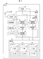
- FIG. 1 is a block diagram showing a specific configuration of the robot 100.
- the robot 100 includes a control unit 20, an antenna unit 10, a reception unit 11, a charging connection unit 12, a charging circuit unit 13, a battery unit 14, a driving unit 15, and a storage unit 16.
- description here is abbreviate
- the receiving unit 11 receives a signal transmitted from a transmitter (not shown) via the antenna unit 10 and transmits the signal to the control unit 20.
- the battery unit 14 supplies power to each unit constituting the robot 100.
- the drive unit 15 includes a number of servo motors 15a corresponding to each joint unit.
- the servo motor 15a includes a motor unit 15b and a driver unit 15c.
- the motor unit 15b drives each drive part by transmitting the motor output generated by the rotation of the shaft constituting the motor part 15b to each drive part such as the shoulder 102 via a transmission mechanism such as a coupling. To do.
- the driver unit 15c compares the rotational position command from the user to the specific servo motor 15a with the rotational position of the servo motor 15a detected by the rotational information detection unit 22 described later, and the drive that flows through the servo motor 15a. The current is controlled.
- the storage unit 16 stores the rotational position (hereinafter “estimated posture information”) of each servomotor 15a corresponding to the posture of the robot estimated by the posture estimation unit 23 (hereinafter referred to as “estimated posture”), standby posture, and the like.
- the rotational position of each servo motor 15a corresponding to (hereinafter referred to as “standby attitude information”), various control programs executed by the control unit 20, and the like are stored.
- the storage unit 16 is configured by a nonvolatile storage device such as a hard disk or a flash memory.
- the posture control device 1 controls the posture of the robot 100 and includes a standby state detection unit 21, a rotation information detection unit 22, a posture estimation unit 23, a standby posture determination unit 24, and a drive control unit 25.
- the standby state detection unit 21 detects a standby state in which all the servo motors 15a should be turned off from the battery unit 14, and transmits the detection result to the rotation information detection unit 22.
- the standby state means that the drive of the servo motor 15a continues, the drive of the servo motor 15a stops unexpectedly, and the voltage of the battery unit 14 decreases so that the robot 100 may be tilted. And / or a situation where charging of the robot 100 is started.
- the posture control device 1 includes the standby state detection unit 21, but the standby state detection unit 21 is not an essential component of the posture control device 1. Therefore, the posture control device 1 may control the posture of the robot 100 regardless of whether or not the robot 100 is in a standby state.
- the rotation information detection unit 22 is a sensor that detects rotation information indicated by the rotation speed and the rotation position of the shaft when the detection result that the robot 100 is in the standby state is received from the standby state detection unit 21.
- an optical encoder is used as the rotation information detection unit 22.
- An optical encoder detects a rotation information detection pattern by reading light from a light emitting diode (LED) with a light receiving element in which dozens of phototransistors are integrated through a position detection pattern on a slit disk. is there. Further, the optical encoder is equipped with a CPU, and the rotation information obtained as a result of analyzing the rotation information detection pattern by the CPU is transmitted to the driver unit 15 c and the posture estimation unit 23.
- LED light emitting diode
- an optical encoder is used as the rotation information detection unit 22, but the present invention is not limited to this.
- an acceleration sensor may be used instead of the optical encoder.
- the posture estimation unit 23 estimates the posture of the robot 100 (hereinafter referred to as an estimated posture) when the rotation information detection process of the rotation information detection unit 22 is executed based on the rotation information obtained by the rotation information detection unit 22. To do.
- an estimation method for example, data in table format in which postures of a plurality of robots 100 assumed and information on the rotational positions and rotational speeds of the shafts of the servo motors 15a are associated with each other is stored in the storage unit 16 in advance. Keep it. Then, the posture of the robot 100 is estimated by referring to the data in the table format and comparing this with the rotation information obtained by the rotation information detection unit 22.
- the estimated posture information which is an estimation result, is transmitted to the storage unit 16 and the standby posture determination unit 24.
- the standby posture determination unit 24 determines whether or not the estimated posture corresponds to the standby posture based on the estimated posture information received from the posture estimation unit 23, and transmits the determination result to the drive control unit 25. Details of the determination method by the standby posture determination unit 24 will be described later.
- the drive control unit 25 controls the drive of each servo motor 15a based on the determination result received from the standby posture determination unit 24. Specifically, when the determination result that the estimated posture corresponds to the standby posture is received, the drive control unit 25 performs control so that all the servo motors 15a are in a power-off state, that is, in a weak state. On the other hand, when the determination result that the estimated posture does not correspond to the standby posture, that is, the non-standby posture described later, is received, the drive control unit 25 determines that the robot 100 is in the standby posture, that is, the physical sitting posture.
- the servo motor 15a (servo motor 15a built in the leg joint portion 107, the knee joint portion 108, and the ankle joint portion 110) corresponding to the transition to the standby posture is driven. Then, after the robot 100 shifts to the standby posture, all the servo motors 15a are controlled so as to be in a power-off state.
- the standby posture determination unit 24 refers to the standby posture information, compares the standby posture information with the estimated posture information, and determines whether or not the two match, thereby determining whether the estimated posture corresponds to the standby posture.
- the standby posture information refers to the rotational position of each servo motor 15a when the robot 100 is in a physical sitting posture.
- the white list method is adopted, all the postures of the robot 100 other than the estimated posture information that are not stored in the storage unit 16 are regarded as non-standby postures described later.
- FIG. 3 are schematic views showing an example of the standby posture of the robot 100.
- the standby posture information related to the standby posture is stored in the storage unit 16. Then, the standby posture information is used as a criterion for determining whether or not the estimated posture corresponds to the standby posture.
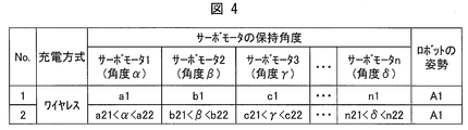
- FIG. 4 is an example of a data table showing the correspondence between the standby posture information and the standby posture.
- the robot 100 when there are n servo motors 15a constituting the drive unit 15, the rotational positions ⁇ , ⁇ ,. .., N1 (standby posture information), the robot 100 is associated with one in the standby posture A1. Then, the standby posture information associated with the standby posture A1 is stored in the storage unit 16 as a criterion for determining whether the estimated posture corresponds to the standby posture.
- the standby posture information and the estimated posture information match means that the rotational positions of the shafts of the servo motors 15a corresponding to the posture of the robot 100 estimated by the posture estimating unit 23 are a1, b1, ..., it means becoming n1.
- the rotational positions ⁇ , ⁇ ,..., ⁇ constituting the standby posture information need not be set to specific values as in the above-described a1, b1,.
- the rotational positions ⁇ , ⁇ ,..., ⁇ are in a certain range such that a21 ⁇ ⁇ a22, b21 ⁇ ⁇ b22,. It may be set to include all values within.
- “the standby posture information and the estimated posture information match” means that the rotational position of the shaft of each servomotor 15a corresponding to the posture of the robot 100 estimated by the posture estimating unit 23 is a21 ⁇ ⁇ . A22, b21 ⁇ ⁇ b21,..., n21 ⁇ ⁇ n22.
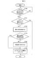
- FIG. 5 is a flowchart showing the control method.
- the standby state detection unit 21 detects that the robot 100 is in a standby state in which all the servomotors 15a should be turned off (YES). Is sent to the rotation information detector 22. On the other hand, when it is detected that the state is not the standby state (NO), the standby state detection unit 21 detects again whether or not the robot 100 is in the standby state (S100: standby state detection step).
- the rotation information detection unit 22 receives a detection result indicating that the robot 100 is in the standby state from the standby state detection unit 21, the rotation information of all the servo motors 15a (the rotation speed and the rotation position of the shaft) is obtained. To detect. When all the servo motors 15a are powered off (YES), that is, when the rotation speeds of the shafts of all the servo motors 15a are 0, the posture of the robot 100 by the posture control device 1 is determined. Control ends (S101: rotation information detection step).
- the posture estimation unit 23 estimates the posture of the robot 100, and transmits estimated posture information as an estimation result to the standby posture determination unit 24 (S102: Posture estimation step).
- the standby posture determination unit 24 determines whether or not the posture of the robot 100 is a standby posture.
- the standby posture determination unit 24 transmits a determination result indicating that it is the standby posture to the drive control unit 25.
- the standby posture determination unit 24 transmits a determination result indicating the non-standby posture to the drive control unit 25.
- the drive control unit 25 controls the drive of the servo motor 15a.
- the drive control unit 25 turns off the power of all the servomotors 15a (the weak state) (S105). : Drive control step).
- the drive control unit 25 causes the servo motor to shift the posture of the robot 100 to the standby posture.
- the drive of 15a is controlled (S104: Standby posture transition process). Then, after shifting to the standby posture, the power of all the servo motors 15a is turned off (S105: drive control process).
- the drive control unit 25 turns off the power to all the servo motors 15a. That is, it is made weak. Therefore, even if the power of all the servo motors 15a is turned off, a large posture change such as tilting of the robot 100 is prevented. For this reason, it is possible to prevent damage to the parts constituting the robot 100 due to the posture change. Further, since the robot 100 can be charged without a large change in posture, in the case of the wireless charging method as in this embodiment, the power receiving coil 12 provided on the sole 105a or the like is provided on the charging stand 12a. It becomes possible to prevent unintentional interruption of charging due to leaving the power transmission coil 12b.
- the robot 100 can be charged with all the servo motors 15a powered off. As a result, the drive current of the servo motor 15a is suppressed, and the charging efficiency can be improved.
- the standby posture determination unit 24 determines whether or not the standby posture is set, and the drive control unit 25 The drive of the servo motor 15a is controlled according to the determination result. Therefore, it is possible to prevent the robot 100 from shifting to the standby posture in a situation not intended by the user. For this reason, it is possible to more efficiently suppress wasteful consumption of the drive current of the servo motor 15a.
- (Modification) 3A is an example of the standby posture of the robot 100, and is not limited to this.
- (a) and (b) of FIG. 6 are schematic diagrams illustrating modifications of the standby posture of the robot 100.
- the robot 100 is in a supine posture (a state in which the arm portion 103 is held substantially horizontal), even if the robot 100 is in a weak state, the transition to the weak state is performed.
- the posture shifts to the supine posture (the arm portion 103 is inclined) as shown in FIG. Therefore, the supine posture in FIG. 6A may be a standby posture instead of the physical sitting posture.
- the supine posture of FIG. 6A is the second standby posture
- standby posture information both first standby posture information, (Second standby posture information) may be stored in the storage unit 16 as a criterion for determining whether or not it corresponds to the standby posture. In this case, if the estimated posture information matches either one of the first standby posture information or the second standby posture information, the estimated posture corresponds to the standby posture.
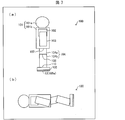
- FIG. 7A is a schematic diagram illustrating an example of the non-standby posture of the robot 100.
- FIG. 7B is a schematic diagram illustrating an example of the posture of the robot 100 that is assumed when the robot 100 enters the weak state from the non-standby posture.
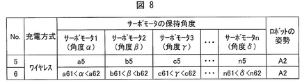
- FIG. 8 is an example of a data table showing the correspondence between the non-standby posture information and the non-standby posture.
- the robot 100 when the robot 100 is in an upright and stationary posture as shown in FIG. 7A, if the robot 100 is put into a weak state, the robot 100 tilts as shown in FIG.
- the coil 12 and the power transmission coil 12b are separated from each other.
- the posture in FIG. 7A is set as the non-standby posture, and the non-standby posture information related to the non-standby posture is compared with the estimated posture information, and when the two do not match, it is determined that the robot 100 is in the standby posture.
- the black list method may be adopted as a determination method by the standby posture determination unit 24.
- the non-standby posture refers to a posture of the robot 100 in which a large posture change such as tilting of the robot 100 may occur when the robot 100 is in a weak state.
- a plurality of postures may be set to a non-standby posture, and these may be used as a criterion for determining whether or not the robot 100 is in the standby posture.
- the black list method is adopted, all the postures of the robot 100 other than the estimated posture information that are not stored in the storage unit 16 are regarded as standby postures.
- the non-standby posture information does not match the estimated posture information
- any of the rotational positions of the shafts of the servomotors 15a corresponding to the posture of the robot 100 estimated by the posture estimating unit 23 is a5. , B5,..., N5.
- the rotational positions ⁇ , ⁇ ,..., ⁇ constituting the non-standby posture information do not need to be set to specific values as in the above a5, b5,.
- the rotational positions ⁇ , ⁇ ,..., ⁇ are in a certain range such as a61 ⁇ ⁇ a62, b61 ⁇ ⁇ b61,. It may be set to include all values within.
- “the non-standby posture information and the estimated posture information do not match” means that any one of the rotational positions of the shafts of the servo motors 15a corresponding to the posture of the robot 100 estimated by the posture estimating unit 23 is a21. ⁇ ⁇ a22, b21 ⁇ ⁇ b21,..., N21 ⁇ ⁇ n22.
- the drive control unit 25 performs control so that all the servomotors 15a are turned off, but the present invention is not limited to this.
- the drive control unit 25 may control the servo motor 15a so as to be in a so-called neutral mode in which the shaft can rotate while the power source of the servo motor 15a is on. Even in the neutral mode, the current consumption of the drive unit 15 can be suppressed as compared with the normal mode.
- the servo motor 15a is used as the drive unit 15, but the present invention is not limited to this.
- an actuator such as a hydraulic cylinder, a pneumatic cylinder, or a linear actuator may be used as the drive unit 15.
- FIGS. 9A and 9B are schematic views illustrating an example of a standby posture of the robot 200 according to the present embodiment.
- the robot 200 according to the present embodiment is different from the first embodiment in that the charging connector 3 is provided with a charging connector 3 instead of the power receiving coil 12 (charging connection unit 12). Different from the robot 100. Therefore, instead of the charging stand 12a used for charging the robot 100 according to the first embodiment, an AC adapter (not shown) including a charging connector connectable to the charging connector 3 on the robot 200 side is used for charging the robot 200. Used.
- the charging connector 3 on the robot 200 side is disposed on the waist 101c constituting the body 101b.
- the arrangement of the charging connector 3 is not limited to the waist portion 101c, and considering the arrangement of the charging connector on the AC adapter side, etc., the connection between the charging connectors is not released even when the robot 200 is in a weak state. What is necessary is just to arrange
- the robot 200 is in a physical sitting position as shown in FIG. 9A, even if the robot 200 is in a weak state, the main body 101 and the arm portion as shown in FIG. 9B.
- the physical sitting position is maintained only by slightly tilting 103. Therefore, it is unlikely that a situation in which the charging of the robot 200 is interrupted, such as the tilting of the robot 200 and the unexpected disconnection between the charging connectors, will occur. Therefore, also in the robot 200, the physical education sitting posture in FIG. 9A is set as the standby posture, similarly to the robot 100 according to the first embodiment.
- the standby posture is not limited to the above-mentioned physical sitting posture, and any posture suitable for charging that prevents a large posture change such as tilting of the robot 200 during charging is possible. Also good.
- the standby posture determination unit 24 used in the present embodiment uses the standby posture information when the physical education sitting posture is the standby posture as the standby posture information and the estimated posture as a determination criterion as to whether or not the robot 200 is in the standby posture. It is determined whether or not the information matches (white list method).
- FIG. 10 is an example of a data table showing the correspondence between the standby posture information of the robot 200 and the standby posture.
- the robot 200 when there are n servo motors 15a constituting the drive unit 15, the rotational positions ⁇ , ⁇ ,. Are a3, b3,..., N3 (standby posture information), respectively, the robot 200 is associated with one in the standby posture A1. Then, the standby posture information associated with the standby posture A1 is stored in the storage unit 16 as a determination criterion for determining whether or not the estimated posture corresponds to the standby posture.
- the rotational positions ⁇ , ⁇ ,..., ⁇ constituting the standby posture information are a41 ⁇ ⁇ a42, b41 ⁇ ⁇ b42,..., N41 ⁇ ⁇ , as indicated by No4 in FIG. It may be set to include all values within a certain range with n42.
- the robot 200 can be charged in a state in which the robot 200 is prevented from being tilted and the unexpected disconnection between the charging connectors is prevented. Therefore, it is possible to prevent unintentional interruption of charging as in the first embodiment.
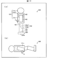
- FIG. 11A is a schematic diagram illustrating an example of the non-standby posture of the robot 200.
- FIG. 11B is a schematic diagram illustrating an example of the posture of the robot 200 that is assumed when the robot 200 is turned off from a non-standby posture.
- FIG. 12 is an example of a data table showing the correspondence between the non-standby posture information of the robot 200 and the standby non-posture.
- FIG. 11 (a) when the robot 200 is in an upright and stationary posture, if the robot 200 is put into a weak state, the robot 200 is tilted as shown in FIG. 11 (b). The connection between the charging connectors will be released.
- the standby posture determination unit 24 compares the non-standby posture information and the estimated posture information regarding the non-standby posture with the posture of FIG. 11A as the non-standby posture. It is determined that the posture is standby.
- the robot 200 when there are n servo motors 15a constituting the drive unit 15, the rotational positions ⁇ , ⁇ ,... Of the shafts of the servo motors 1, 2,. , ⁇ are a7, b7,..., N7 (non-standby posture information), the robot 200 is associated with the non-standby posture A2. Then, the non-standby posture information associated with the non-standby posture A2 is stored in the storage unit 16 as a determination criterion when determining whether the estimated posture corresponds to the standby posture.
- the rotational positions ⁇ , ⁇ ,..., ⁇ constituting the non-standby posture information are a81 ⁇ ⁇ a82, b81 ⁇ ⁇ b81,..., N81 ⁇ , as indicated by No8 in FIG. ⁇ It is the same as that of Embodiment 1 that it may be set so that all the values which are in a certain range with n82 may be included.
- the point that the drive control unit 25 may control the servo motor 15a so that the servo motor 15a is in the neutral mode and the point that an actuator may be used as the drive unit 15 are the same as in the first embodiment.
- the robot 300 according to the present embodiment is different from the robots 100 and 200 according to the first and second embodiments in that the robot 300 is switched to the standby mode when there is no command from the user for a certain period of time.
- the standby mode means that the posture of the robot 300 is shifted to a standby posture in which the robot 300 can maintain a constant posture regardless of the driving state of the servo motor 15a, and all the servo motors 15a are powered after the transition. It means being in the OFF state.
- the “constant posture” refers to a series of postures of the robot 300 in which a stationary state suitable for standby is maintained regardless of the driving state of the servo motor 15a.
- FIG. 13 is a block diagram showing a specific configuration of the robot 300 according to the present embodiment.
- the robot 300 is provided with a standby state detection unit 31 that detects whether the robot 300 is in a standby state based on the reception state of the reception unit 11 instead of the standby state detection unit 21. It differs from the embodiment in that the control device 2 is mounted.
- the standby status detection unit 31 is a standby status in which all the servo motors 15a should be turned off from the reception unit 11, that is, the reception unit 11 has not received radio waves from a transmitter (not shown) for a certain period of time. Or not, and the detection result is transmitted to the rotation information detection unit 22.
- fixed time is an arbitrary set value.
- the standby state detection unit 31 determines the actual time when the reception unit 11 is not receiving radio waves, and the user You may make it contrast with the time input into. Further, for example, the time desired by the user may be stored in the storage unit 16 in advance.
- the outline of the robot 300 and the determination method by the standby posture determination unit 24 are the same as in the first or second embodiment, and the posture control device 2 uses the same posture control method as in the first and second embodiments. The description is omitted.
- the robot 300 switches to the standby mode when there is no command from the user for a certain period of time. Since all the servo motors 15a are powered off during the standby mode, the drive current of the servo motors 15a can be suppressed. For this reason, it is possible to more efficiently suppress wasteful consumption of the drive current of the servo motor 15a.
- the blacklist method may be adopted as a determination method by the standby posture determination unit 24, and a plurality of variations may be provided for the standby posture and the non-standby posture.
- the non-standby posture refers to the posture of the robot 300 that may cause a large posture change depending on the driving state of the servo motor 15a.
- the drive control unit 25 may control the servo motor 15a so that the servo motor 15a is in the neutral mode, and an actuator may be used as the drive unit 15. It is.
- control blocks (especially the control unit 20 and the control unit 30) of the attitude control devices 1 and 2 may be realized by a logic circuit (hardware) formed in an integrated circuit (IC chip) or the like, or a CPU (Central Processing) Unit) and may be realized by software.
- a logic circuit hardware
- IC chip integrated circuit
- CPU Central Processing
- the attitude control devices 1 and 2 include a CPU that executes instructions of a program that is software that implements each function, and a ROM (Read Only) in which the program and various data are recorded so as to be readable by the computer (or CPU).
- Memory or a storage device (these are referred to as “recording media”), a RAM (Random Access Memory) for expanding the program, and the like.
- the objective of this invention is achieved when a computer (or CPU) reads the said program from the said recording medium and runs it.
- a “non-temporary tangible medium” such as a tape, a disk, a card, a semiconductor memory, a programmable logic circuit, or the like can be used.
- the program may be supplied to the computer via an arbitrary transmission medium (such as a communication network or a broadcast wave) that can transmit the program.
- a transmission medium such as a communication network or a broadcast wave
- the present invention can also be realized in the form of a data signal embedded in a carrier wave in which the program is embodied by electronic transmission.
- the posture control device (1, 2) is a robot that can change its posture by controlling the drive of the drive unit (15) provided in the movable part of the robot (100, 200, 300).
- An attitude control device for controlling an attitude, the driving position detecting unit (rotation information detecting unit 22) for detecting the driving position of the driving unit, and the driving position detected by the driving position detecting unit based on the driving position Whether the posture estimated by the posture estimator (23) for estimating the posture of the robot and the posture estimated by the posture estimator is a standby posture in which the robot can maintain a constant posture regardless of the drive maintenance of the drive unit.
- a standby posture determination unit (24) that determines whether or not, and a drive control unit (25) that puts the drive unit into a non-driven state when the standby posture determination unit determines that the standby posture is the standby posture. Yes.
- the posture estimation unit can estimate the posture of the robot based on the drive position of the drive unit detected by the drive position detection unit. Further, the drive control unit puts the drive unit into a non-driven state when the estimated posture of the robot is determined as the standby posture by the standby posture determination unit. Therefore, even if the driving unit is in a non-driving state, that is, a weak state, a large change in posture such as tilting of the robot is prevented. For this reason, it is possible to prevent damage to parts constituting the robot due to the posture change.
- the standby posture is set to a charging posture in which the robot can be charged, charging is performed in a state where the driving unit is not driven. Therefore, the drive current of the drive unit can be suppressed, and the charging efficiency can be improved.
- the robot can be charged without a large posture change even if the driving unit is in a non-driving state. Therefore, for example, in the case of the wireless charging method, the power receiving coil provided in a specific part of the robot such as the sole is separated from the power transmitting coil provided in the charging stand, or in the case of the AC adapter method. It is possible to prevent unintentional interruption of charging due to the charging connector provided in the specific part being separated from the charging connector on the AC adapter side.
- the attitude control device (1, 2) is the above aspect 1, in which the drive control unit (25) determines that the standby attitude determination unit (24) is not in the standby attitude.
- the drive of the drive unit (15) may be controlled so that the robot (100, 200, 300) is in the standby posture, and the drive unit is brought into a non-drive state after shifting to the standby posture. .
- the standby posture is set to the above charging posture, charging is performed in a state where the driving unit is not driven, so that it is possible to improve the charging efficiency.
- the robot can be charged without a large change in posture, it is possible to prevent unintentional interruption of charging.
- the standby posture determination unit (24) is configured such that the robot (100, 200, 300) is the driving unit (15). It may be determined whether or not the vehicle is in the standby posture when the vehicle is in a standby state where it should be in a non-driven state.
- the standby posture determination unit operates when the robot is in the standby state, it is possible to prevent the robot from shifting to the standby posture in a situation not intended by the user. Therefore, it is possible to more efficiently suppress wasteful consumption of the drive current of the drive unit.
- the robot (100, 200, 300) according to aspect 4 of the present invention may include the attitude control device (1, 2) according to any one of the aspects 1 to 3.
- the attitude control device may be realized by a computer.
- the attitude control device is realized by the computer by causing the computer to operate as each unit included in the attitude control device.
- the attitude control program for the control device also falls within the scope of the present invention.
- the present invention can be used to prevent damage to parts constituting the robot and to reduce current consumption when charging various robots.
Landscapes
- Engineering & Computer Science (AREA)
- Robotics (AREA)
- Mechanical Engineering (AREA)
- Manipulator (AREA)
Abstract
ロボットを構成する部品等の破損を防ぐとともに駆動部の消費電流を抑制する。姿勢制御装置(1)は、駆動部(15)の駆動位置を検出する駆動位置検出部(22)と、駆動位置に基づいてロボット(100)の姿勢を推定する姿勢推定部(23)と、推定されたロボット(100)の姿勢が待機姿勢であるか否かを判定する待機姿勢判定部(24)と、駆動部(15)を非駆動状態にする駆動制御部(25)と、を備えている。
Description
本発明は、ロボットの姿勢を制御する姿勢制御装置、ロボットおよびプログラムに関する。
充電時におけるロボットの姿勢を制御する技術が広く研究されている。例えば、特許文献1には、充電用コネクタを介して外部電源に接続可能なバッテリーから通電されて移動機構と作業機構を駆動する電動アクチュエータを備えた移動ロボットにおいて、充電状況の如何に関わらず、姿勢の不安定化を防止すると共に、作業機構の動作要求に応えるようにした当該移動ロボットの制御装置が開示されている。
しかしながら、特許文献1に開示された制御装置は、充電時における移動ロボットの姿勢を安定化させるためのものであり、充電時以外で移動ロボットの姿勢の安定化が必要な場合の当該移動ロボットの姿勢を制御するものではない。したがって、前記のような場合に、例えば、移動ロボットが傾倒してしまい、当該移動ロボットを構成する部品または充電コネクタ等が破損するおそれがあった。また、移動ロボットに備えられた電動アクチュエータの電源は充電中においてもONの状態であることから、当該電動アクチュエータの駆動電流の消費量が多くなり、充電効率が悪化してしまうという問題があった。
本発明は、上記の問題点に鑑みてなされたものであり、その目的は、充電時を始めとするロボットの姿勢の安定化が必要な場合において、ロボットの傾倒等による当該ロボットを構成する部品等の破損を防ぐとともに、駆動部の消費電流を抑制することが可能な姿勢制御装置等を実現することにある。
上記の課題を解決するために、本発明の一態様に係る姿勢制御装置は、ロボットの可動部位に設けられる駆動部の駆動を制御することにより、姿勢変更可能なロボットの姿勢を制御する姿勢制御装置であって、上記駆動部の駆動位置を検出する駆動位置検出部と、上記駆動位置検出部によって検出される上記駆動位置に基づいて、上記ロボットの姿勢を推定する姿勢推定部と、上記姿勢推定部によって推定される上記姿勢が、上記駆動部の駆動維持に係らず一定の姿勢を保持し得る待機姿勢であるか否かを判定する待機姿勢判定部と、上記待機姿勢判定部が上記待機姿勢であると判定する場合、上記駆動部を非駆動状態にする駆動制御部と、を備えている。
本発明の一態様によれば、電動アクチュエータ等の駆動部の駆動維持に拘らず、ロボットの姿勢が不安定な状態にならないように当該ロボットの姿勢を制御することで、ロボットの傾倒等による当該ロボットを構成する部品等の破損を防ぐとともに、駆動部の消費電流を抑制することが可能な姿勢制御装置等を実現することができる。
〔実施形態1〕
以下、本発明の実施の形態について、図1~図8を参照しながら、詳細に説明する。なお、下記の実施形態においては、姿勢制御装置が2足歩行ヒューマノイドロボットに搭載されるものとして説明するが、これに限らず、例えば、アニメキャラクタの戦闘ロボットまたは動物ロボット等のロボット全般に搭載されてもよい。
以下、本発明の実施の形態について、図1~図8を参照しながら、詳細に説明する。なお、下記の実施形態においては、姿勢制御装置が2足歩行ヒューマノイドロボットに搭載されるものとして説明するが、これに限らず、例えば、アニメキャラクタの戦闘ロボットまたは動物ロボット等のロボット全般に搭載されてもよい。
(ロボットの概要)
まず、図2の(a)を参照してロボット100の概要について説明する。図2の(a)は、本実施形態に係るロボット100の概略構成を示す模式図である。
まず、図2の(a)を参照してロボット100の概要について説明する。図2の(a)は、本実施形態に係るロボット100の概略構成を示す模式図である。
図2の(a)に示すように、ロボット100は、本体部101、肩部102、腕部103、脚部104、および足部105で構成される。本体部101は、頭部101aと胴体部101bとで構成され、脚部104は、上脚部104aと下脚部104bとで構成される。肩部102は肩関節部106を介して、脚部104は脚関節部107を介して、それぞれ胴体部101bに対して可動に接続されている。また、下脚部104bは膝関節部108を介して上脚部104aに対して、腕部103は腕関節部109を介して肩部102に対して、足部105は足関節部110を介して脚部104に対して、それぞれ可動に接続されている。
各関節部には、後述するサーボモータ15aが内蔵されており、当該サーボモータ15aが駆動することによって、肩部102、腕部103、上脚部104a、下脚部104b、および足部105はそれぞれ可動する。
次に、胴体部101bには、制御部20、充電回路部13、および後述するバッテリー部14(図示せず)が内蔵されている。また、足部105を構成する足裏部105aには、後述する充電接続部12として受電コイル12が設けられているとともに、バッテリー部14を充電するための充電台12aにおける、当該足裏部105aと接触する側の面(以下、「上面」とする)には、送電コイル12bが設けられている。
制御部20は、ロボット100を統括的に制御するものであり、姿勢制御装置1を備えている。姿勢制御装置1は、ロボット100の姿勢を制御するための各種処理を統括するものであり、その詳細については後述する。
充電接続部12は、充電台12aの送電コイル12bに流れる電流に起因して当該充電接続部12に発生する電流を充電回路部13に供給するものであり、本実施形態においては、充電接続部12として受電コイルが採用されている。
充電回路部13は、バッテリー部14に配線されており、当該バッテリー部14を充電するための電気回路である。また、充電回路部13は、脚部104内部に電気配線を挿通させることによって受電コイル12にも配線される。
(充電時におけるロボットの姿勢移行の概要)
次に、図2の(a)および(b)を参照して、充電時におけるロボット100の姿勢移行の概要について説明する。図2の(a)および(b)は、充電時におけるロボット100の姿勢移行の概要を示す模式図である。
次に、図2の(a)および(b)を参照して、充電時におけるロボット100の姿勢移行の概要について説明する。図2の(a)および(b)は、充電時におけるロボット100の姿勢移行の概要を示す模式図である。
図2の(a)に示すように、ロボット100が充電を必要とする状態になったとき、当該ロボット100は、受電コイル12が送電コイル12bと近接するように充電台12a上に移動し、直立不動の姿勢で一旦静止する。ここで、「受電コイル12が送電コイル12bと近接する」とは、足裏部105aの表面が充電台12aの上面と接触し、かつ、受電コイル12が送電コイル12bの上方に配置されることをいう。
そして、当該直立不動の姿勢から、脚関節部107および膝関節部108に内蔵されたサーボモータ15aを駆動することによって上脚部104aおよび下脚部104bが作動する。そして、ロボット100の傾倒等の大きな姿勢変化による充電の中断が防止される充電に適した姿勢(以下、「待機姿勢」とする)に移行する。本実施形態では、待機姿勢としていわゆる体育座りの姿勢を採用する。但し、上記姿勢移行の前後において足裏部105aと充電台12a上面との接触を維持し充電が行えるように、足関節部110に内蔵されたサーボモータ15aが駆動する。待機姿勢に移行後は、全てのサーボモータ15aは電源OFFの状態、すなわち脱力状態となる。
ここで、充電台12aにはACアダプタ12cが接続されており、当該ACアダプタ12cから供給された電力によって送電コイル12bに電流が流れる。それに伴って、送電コイル12bと近接する足裏部105aの受電コイル12にも、電磁誘導現象によって電流が流れる。そして、受電コイル12を流れる電流は電気配線を通じて充電回路部13、バッテリー部14の順に流れていき、バッテリー部14が充電される(電磁誘導方式によるワイヤレス充電)。
(ロボットの具体的構成)
次に、ロボット100の具体的構成について、図1を参照しながら説明する。図1は、ロボット100の具体的構成を示すブロック図である。
次に、ロボット100の具体的構成について、図1を参照しながら説明する。図1は、ロボット100の具体的構成を示すブロック図である。
図1に示すように、ロボット100は、制御部20、アンテナ部10、受信部11、充電接続部12、充電回路部13、バッテリー部14、駆動部15、および記憶部16を備えている。なお、上述した構成については、ここでの説明を省略する。
受信部11は、アンテナ部10を介して、送信機(図示せず)から送信された信号を受信し、当該信号を制御部20に送信するものである。バッテリー部14は、ロボット100を構成する各部に電力の供給を行うものである。
駆動部15は、各関節部に対応する数のサーボモータ15aで構成される。また、サーボモータ15aはモータ部15bとドライバ部15cとを備えている。モータ部15bは、当該モータ部15bを構成するシャフトの回転によって生じるモータ出力を、カップリング等の伝達機構を介して肩部102等の各駆動部位に伝達することで、当該各駆動部位を駆動するものである。ドライバ部15cは、ユーザによる特定のサーボモータ15aへの回転位置指令と、後述する回転情報検出部22によって検出された当該サーボモータ15aの回転位置とを比較して、当該サーボモータ15aに流れる駆動電流を制御するものである。
記憶部16は、後述する姿勢推定部23によって推定されたロボットの姿勢(以下、「推定姿勢」とする)に対応する各サーボモータ15aの回転位置(以下、「推定姿勢情報」)、待機姿勢に対応する各サーボモータ15aの回転位置(以下、「待機姿勢情報」)、および制御部20が実行する各種の制御プログラム等を記憶するものである。記憶部16は、例えばハードディスク、フラッシュメモリなどの不揮発性の記憶装置によって構成される。
次に、姿勢制御装置1の具体的構成について説明する。姿勢制御装置1は、ロボット100の姿勢を制御するものであり、待機状況検知部21、回転情報検出部22、姿勢推定部23、待機姿勢判定部24、および駆動制御部25を備えている。
待機状況検知部21は、バッテリー部14から、全てのサーボモータ15aの電源をOFFにすべき待機状況を検知し、検知結果を回転情報検出部22に送信するものである。ここで、待機状況とは、サーボモータ15aの駆動が継続することで当該サーボモータ15aの駆動が不意に停止し、ロボット100の傾倒等が生ずる可能性があるほどにバッテリー部14の電圧が低下している状況、およびロボット100の充電が開始された状況の少なくともいずれか一方をいう。
なお、本実施形態では、姿勢制御装置1は待機状況検知部21を備えているが、当該待機状況検知部21は当該姿勢制御装置1の必須の構成要素ではない。したがって、姿勢制御装置1は、ロボット100が待機状況にあるか否かに拘らず、当該ロボット100の姿勢を制御するものであってもよい。
回転情報検出部22は、待機状況検知部21からロボット100が待機状況であるとの検知結果を受信した場合に、シャフトの回転速度と回転位置とで示される回転情報を検出するセンサである。回転情報検出部22としては、例えば光学式エンコーダが用いられる。光学式エンコーダは、発光ダイオード(LED)からの光を、スリット円盤上の位置検出パターンを通してフォトトランジスタが数十個分集積された受光素子で読み取ることで、回転情報検出用パターンを検出するものである。また、光学式エンコーダにはCPUが搭載されており、当該CPUで回転情報検出用パターンを分析した結果得られた回転情報を、ドライバ部15cおよび姿勢推定部23に送信する。
なお、本実施形態では、回転情報検出部22として光学式エンコーダが用いられているが、これに限定される訳ではない。光学式エンコーダに代えて、例えば加速度センサを用いてもよい。
姿勢推定部23は、回転情報検出部22によって得られた回転情報に基づいて、当該回転情報検出部22の回転情報検出処理の実行時におけるロボット100の姿勢(以下、推定姿勢とする)を推定するものである。推定方法としては、例えば、想定される複数のロボット100の姿勢と、各サーボモータ15aのシャフトの回転位置および回転速度に関する情報とが対応付けられたテーブル形式のデータをあらかじめ記憶部16に記憶させておく。そして、当該テーブル形式のデータを参照し、これと回転情報検出部22によって得られた回転情報とを対比してロボット100の姿勢を推定する。推定結果である上記推定姿勢情報は、記憶部16および待機姿勢判定部24に送信される。
待機姿勢判定部24は、姿勢推定部23から受信した推定姿勢情報に基づいて、推定姿勢が待機姿勢に該当するか否かを判定し、判定結果を駆動制御部25に送信するものである。待機姿勢判定部24による判定方法の詳細については後述する。
駆動制御部25は、待機姿勢判定部24から受信した判定結果に基づいて、各サーボモータ15aの駆動を制御するものである。具体的には、推定姿勢が待機姿勢に該当するとの判定結果を受信した場合、駆動制御部25は、全てのサーボモータ15aが電源OFFの状態、すなわち脱力状態となるよう制御する。一方、推定姿勢が待機姿勢に該当しない、すなわち、後述する非待機姿勢に該当するとの判定結果を受信した場合、駆動制御部25は、ロボット100が待機姿勢、すなわち体育座り姿勢となるよう、当該待機姿勢への移行に対応するサーボモータ15a(脚関節部107、膝関節部108、および足関節部110に内蔵されたサーボモータ15a)を駆動する。そして、ロボット100が待機姿勢に移行した後に、全てのサーボモータ15aが電源OFFの状態になるよう制御する。
(待機姿勢判定部による判定方法)
次に、待機姿勢判定部24による判定方法について、図3および図4を参照しながら説明する。
次に、待機姿勢判定部24による判定方法について、図3および図4を参照しながら説明する。
待機姿勢判定部24は、待機姿勢情報を参照し、当該待機姿勢情報と推定姿勢情報とを対比して両者が一致するか否かを判定することで、推定姿勢が待機姿勢に該当するか否かを判定する(ホワイトリスト方式)。ここで、待機姿勢情報とは、ロボット100が体育座り姿勢になっている時の各サーボモータ15aの回転位置をいう。なお、ホワイトリスト方式を採用する場合、推定姿勢情報以外で記憶部16に記憶されていないロボット100の姿勢は、全て後述する非待機姿勢とみなされる。
ここで、図3の(a)および(b)は、ロボット100の待機姿勢の一例を示す概略図である。
まず、図3の(a)に示すように、ロボット100が体育座り姿勢(本実施形態における待機姿勢)の場合、当該ロボット100が脱力状態にすると、図3の(b)のような姿勢に移行するものと想定される。ここで、ロボット100が図3の(b)のような姿勢になったとしても、当該ロボット100の姿勢が不安定になる可能性は低いことから、図3の(a)の姿勢を待機姿勢として、当該待機姿勢に関する待機姿勢情報が記憶部16に記憶される。そして、当該待機姿勢情報を、推定姿勢が待機姿勢に該当するか否かを判定する際の判定基準とする。
次に、図4は、待機姿勢情報と待機姿勢との対応関係を示すデータテーブルの一例である。
図4のNo1に示すように、駆動部15を構成するサーボモータ15aがn個ある場合、各サーボモータ1、2、・・・、nのシャフトの回転位置α、β、・・・、δが、それぞれa1、b1、・・・、n1の場合(待機姿勢情報)、ロボット100は待機姿勢A1にあるものと対応付けられる。そして、待機姿勢A1と対応関係付けられた当該待機姿勢情報が、推定姿勢が待機姿勢に該当するか否かを判定する際の判定基準として記憶部16に記憶される。この場合、「待機姿勢情報と推定姿勢情報とが一致する」とは、姿勢推定部23によって推定されたロボット100の姿勢に対応する各サーボモータ15aのシャフトの回転位置が、それぞれa1、b1、・・・、n1になることをいう。
なお、待機姿勢情報を構成する回転位置α、β、・・・、δは、上述のa1、b1、・・・、n1のように特定の値に設定される必要はない。例えば図4のNo2に示すように、回転位置α、β、・・・、δは、それぞれa21<α<a22、b21<β<b22、・・・、n21<δ<n22のように一定範囲内にある値をすべて包含するよう設定されてもよい。この場合、「待機姿勢情報と推定姿勢情報とが一致する」とは、姿勢推定部23によって推定されたロボット100の姿勢に対応する各サーボモータ15aのシャフトの回転位置が、それぞれa21<α<a22、b21<β<b21、・・・、n21<δ<n22の範囲内にあることをいう。
(姿勢制御装置によるロボットの姿勢の制御方法)
次に、図5を用いて、姿勢制御装置1によるロボット100の姿勢の制御方法について説明する。図5は、当該制御方法を示すフローチャートである。
次に、図5を用いて、姿勢制御装置1によるロボット100の姿勢の制御方法について説明する。図5は、当該制御方法を示すフローチャートである。
図5に示すように、まず、待機状況検知部21は、ロボット100が全てのサーボモータ15aの電源をOFFにすべき待機状況であることを検知した場合(YES)、当該待機状況である旨の検知結果を回転情報検出部22に送信する。一方、待機状況でないことを検知した場合(NO)、待機状況検知部21は、ロボット100が待機状況であるか否かを再び検知する(S100:待機状況検知工程)。
次に、回転情報検出部22は、待機状況検知部21からロボット100が待機状況である旨の検知結果を受信した場合、全てのサーボモータ15aの回転情報(シャフトの回転速度および回転位置)を検出する。そして、全てのサーボモータ15aの電源がOFFになっている場合(YES)、すなわち、全てのサーボモータ15aのシャフトの回転速度が0になっている場合、姿勢制御装置1による当該ロボット100の姿勢制御は終了する(S101:回転情報検出工程)。
一方、全てのサーボモータ15aの電源がOFFにはなっていない場合(NO)、すなわち、特定のサーボモータ15aのシャフトの回転速度のみが0になっている場合、回転情報検出部22は、全てのサーボモータ15aの回転情報を姿勢推定部23に送信する(S101:回転情報検出工程)。
次に、回転情報検出部22から受信した上記回転情報に基づいて、姿勢推定部23はロボット100の姿勢を推定し、推定結果である推定姿勢情報を待機姿勢判定部24に送信する(S102:姿勢推定工程)。
次に、姿勢推定部23から受信した上記推定姿勢情報に基づいて、待機姿勢判定部24はロボット100の姿勢が待機姿勢であるか否かを判定する。当該ロボット100の姿勢を待機姿勢であると判定した場合(YES)、待機姿勢判定部24は待機姿勢である旨の判定結果を駆動制御部25に送信する。一方、待機姿勢でないと判定した場合(NO)、すなわち、後述する非待機姿勢であると判定した場合、待機姿勢判定部24は非待機姿勢である旨の判定結果を駆動制御部25に送信する(S103:待機姿勢判定工程)。
次に、待機姿勢判定部24から受信した判定結果に基づいて、駆動制御部25はサーボモータ15aの駆動を制御する。待機姿勢判定部24から待機姿勢である旨の判定結果が送信された場合(S103でYES)、駆動制御部25は、全てのサーボモータ15aの電源をOFFの状態(脱力状態)にする(S105:駆動制御工程)。
一方、待機姿勢判定部24から後述する非待機姿勢であるとの判定結果が送信された場合(S103でNO)、駆動制御部25は、ロボット100の姿勢が待機姿勢に移行するようにサーボモータ15aの駆動を制御する(S104:待機姿勢移行工程)。そして、待機姿勢への移行後に、全てのサーボモータ15aの電源をOFFの状態にする(S105:駆動制御工程)。
(効果)
以上のように、本実施形態によれば、駆動制御部25は、推定されるロボット100の姿勢が待機姿勢判定部24によって待機姿勢と判定された場合、全てのサーボモータ15aの電源をOFF、すなわち脱力状態にする。したがって、全てのサーボモータ15aの電源をOFFにしても、ロボット100の傾倒等の大きな姿勢変化は防止される。そのため、当該姿勢変化による、当該ロボット100を構成する部品等の破損を防ぐことが可能となる。さらに、大きな姿勢変化を伴わずにロボット100を充電できることから、本実施形態のようなワイヤレス充電方式の場合であれば、足裏部105a等に設けられた受電コイル12が、充電台12aに設けられた送電コイル12bから離れたりすることによる、意図しない充電の中断を防ぐことが可能となる。
以上のように、本実施形態によれば、駆動制御部25は、推定されるロボット100の姿勢が待機姿勢判定部24によって待機姿勢と判定された場合、全てのサーボモータ15aの電源をOFF、すなわち脱力状態にする。したがって、全てのサーボモータ15aの電源をOFFにしても、ロボット100の傾倒等の大きな姿勢変化は防止される。そのため、当該姿勢変化による、当該ロボット100を構成する部品等の破損を防ぐことが可能となる。さらに、大きな姿勢変化を伴わずにロボット100を充電できることから、本実施形態のようなワイヤレス充電方式の場合であれば、足裏部105a等に設けられた受電コイル12が、充電台12aに設けられた送電コイル12bから離れたりすることによる、意図しない充電の中断を防ぐことが可能となる。
また、本実施形態によれば、全てのサーボモータ15aの電源をOFFにした状態でロボット100の充電を行うことができる。そのため、サーボモータ15aの駆動電流が抑えられ、充電効率の向上を図ることが可能となる。
さらに、本実施形態によれば、待機状況検知部21によってロボット100が待機状況にあることが検知された場合に、待機姿勢判定部24は待機姿勢か否かを判定し、駆動制御部25は判定結果に応じてサーボモータ15aの駆動を制御する。したがって、ユーザの意図しない状況でロボット100が待機姿勢に移行することを防止することが可能となる。そのため、サーボモータ15aの駆動電流の無駄な消費をより効率的に抑えることが可能となる。
(変形例)
なお、図3の(a)に示すような体育座り姿勢は、ロボット100の待機姿勢の一例であり、これに限定される訳ではない。ここで、図6の(a)および(b)は、ロボット100の待機姿勢の変形例を示す概略図である。
なお、図3の(a)に示すような体育座り姿勢は、ロボット100の待機姿勢の一例であり、これに限定される訳ではない。ここで、図6の(a)および(b)は、ロボット100の待機姿勢の変形例を示す概略図である。
例えば図6の(a)に示すように、ロボット100が仰向けの姿勢(腕部103が略水平に保持された状態)であれば、当該ロボット100を脱力状態にしても当該脱力状態への移行前後で姿勢変化のほとんどない、図6の(b)に示すような仰向けの姿勢(腕部103が傾斜した状態)に移行する。したがって、図6の(a)の仰向け姿勢を、上記体育座り姿勢に代えて待機姿勢としてもよい。
さらには、図3の(a)の体育座り姿勢を第1待機姿勢、図6の(a)の仰向け姿勢を第2待機姿勢とし、両姿勢の待機姿勢情報(それぞれ、第1待機姿勢情報、第2待機姿勢情報とする)を待機姿勢に該当するか否かの判定基準として、記憶部16に記憶させてもよい。この場合、推定姿勢情報が第1待機姿勢情報または第2待機姿勢情報のいずれか一つに一致すれば、当該推定姿勢は待機姿勢に該当することとなる。
次に、本実施形態では、待機姿勢判定部24による判定方法としてホワイトリスト方式を採用しているが、これに限定される訳ではない。ここで、図7の(a)は、ロボット100の非待機姿勢の一例を示す概略図である。また、図7の(b)は、ロボット100が非待機姿勢から脱力状態になった場合に想定される、当該ロボット100の姿勢の一例を示す概略図である。さらに、図8は、非待機姿勢情報と非待機姿勢との対応関係を示すデータテーブルの一例である。
例えば、図7の(a)に示すようにロボット100が直立不動の姿勢の場合、当該ロボット100を脱力状態にすれば、図7の(b)に示すように当該ロボット100は傾倒し、受電コイル12と送電コイル12bとが離間してしまう。
そこで、図7の(a)の姿勢を非待機姿勢として、当該非待機姿勢に関する非待機姿勢情報と推定姿勢情報とを対比し、両者が一致しない場合にロボット100が待機姿勢であると判定するブラックリスト方式を、待機姿勢判定部24による判定方法として採用してもよい。ここで、非待機姿勢とは、ロボット100を脱力状態にした場合に、当該ロボット100の傾倒等の大きな姿勢変化が生じる可能性のある、当該ロボット100の姿勢のことをいう。
なお、非待機姿勢は複数想定されることから、図7の(a)の姿勢に限定する必要はなく、別の姿勢を非待機姿勢にしたり、または、図7の(a)の姿勢を含む複数の姿勢を非待機姿勢にしたりして、これらをロボット100が待機姿勢にあるか否かの判定基準としてもよい。また、ブラックリスト方式を採用する場合、推定姿勢情報以外で記憶部16に記憶されていないロボット100の姿勢は、全て待機姿勢とみなされる。
そして、図8のNo5に示すように、駆動部15を構成するサーボモータ15aがn個ある場合、各サーボモータ1、2、・・・、nのシャフトの回転位置α、β、・・・、δが、それぞれa5、b5、・・・、n5の場合(非待機姿勢情報)、ロボット100は非待機姿勢A2にあるものと対応付けられる。そして、非待機姿勢A2と対応関係付けられた当該非待機姿勢情報が、推定姿勢が待機姿勢に該当するか否かを判定する際の判定基準として記憶部16に記憶される。この場合、「非待機姿勢情報と推定姿勢情報とが一致しない」とは、姿勢推定部23によって推定されたロボット100の姿勢に対応する各サーボモータ15aのシャフトの回転位置のいずれかが、a5、b5、・・・、n5のいずれかと異なることをいう。
なお、非待機姿勢情報を構成する回転位置α、β、・・・、δは、上述のa5、b5、・・・、n5のように特定の値に設定される必要はない。例えば図8のNo6に示すように、回転位置α、β、・・・、δは、それぞれa61<α<a62、b61<β<b61、・・・、n61<δ<n62のように一定範囲内にある値をすべて包含するよう設定されてもよい。この場合、「非待機姿勢情報と推定姿勢情報とが一致しない」とは、姿勢推定部23によって推定されたロボット100の姿勢に対応する各サーボモータ15aのシャフトの回転位置のいずれかが、a21<α<a22、b21<β<b21、・・・、n21<δ<n22のいずれかの範囲外にあることをいう。
次に、本実施形態では、駆動制御部25は、全てのサーボモータ15aの電源がOFFの状態になるよう制御するが、これに限定される訳ではない。例えば、駆動制御部25は、サーボモータ15aの電源はONの状態のままでシャフトが回動自在の状態となる、いわゆるニュートラルモードになるよう、当該サーボモータ15aを制御してもよい。なお、ニュートラルモードであっても、通常モードに比して、駆動部15の消費電流を抑制することが可能である。
次に、本実施形態では、駆動部15としてサーボモータ15aを用いているがこれに限定される訳ではない。例えば、駆動部15として、油圧シリンダ、空圧シリンダ、またはリニアアクチュエータ等のアクチュエータを用いてもよい。
〔実施形態2〕
本発明の他の実施形態について、図9~図12に基づいて説明すれば、以下のとおりである。なお、説明の便宜上、前記実施形態にて説明した部材と同じ機能を有する部材については、同じ符号を付記し、その説明を省略する。
本発明の他の実施形態について、図9~図12に基づいて説明すれば、以下のとおりである。なお、説明の便宜上、前記実施形態にて説明した部材と同じ機能を有する部材については、同じ符号を付記し、その説明を省略する。
(ロボットの待機姿勢)
図9の(a)および(b)は、本実施形態に係るロボット200の待機姿勢の一例を示す概略図である。
図9の(a)および(b)は、本実施形態に係るロボット200の待機姿勢の一例を示す概略図である。
図9の(a)に示すように、本実施形態に係るロボット200は、充電接続部3として受電コイル12(充電接続部12)に代えて充電コネクタ3を備えている点で実施形態1に係るロボット100と異なる。そのため、実施形態1に係るロボット100の充電に用いられる充電台12aに代えて、ロボット200側の充電コネクタ3と接続可能な充電コネクタを備えるACアダプタ(図示せず)が、ロボット200の充電に用いられる。
ロボット200側の充電コネクタ3は、胴体部101bを構成する腰部101cに配置される。ただし、当該充電コネクタ3の配置は腰部101cに限定される訳ではなく、ACアダプタ側の充電コネクタの配置等を考慮して、ロボット200が脱力状態になっても充電コネクタ間の接続が解除されないような部位に、当該充電コネクタ3が配置されればよい。
また、ロボット200が、図9の(a)に示すような体育座り姿勢であれば、当該ロボット200が脱力状態になっても、図9の(b)に示すように本体部101および腕部103が若干傾倒するのみで体育座り姿勢は維持される。したがって、ロボット200の傾倒および充電コネクタ間の不意の接続解除といった、ロボット200の充電が中断してしまうような状況が生じる可能性は小さい。そのため、ロボット200においても、実施形態1に係るロボット100と同様に図9の(a)の体育座り姿勢を待機姿勢とする。
なお、待機姿勢は、上記体育座り姿勢に限定される訳ではなく、充電時のロボット200の傾倒等の大きな姿勢変化が防止される充電に適した姿勢であれば、どのような姿勢であってもよい。
(待機姿勢判定部による判定方法)
本実施形態に用いられる待機姿勢判定部24は、上記体育座り姿勢を待機姿勢とした場合の待機姿勢情報を、ロボット200が待機姿勢であるか否かの判定基準として当該待機姿勢情報と推定姿勢情報とが一致するか否かを判定する(ホワイトリスト方式)。
本実施形態に用いられる待機姿勢判定部24は、上記体育座り姿勢を待機姿勢とした場合の待機姿勢情報を、ロボット200が待機姿勢であるか否かの判定基準として当該待機姿勢情報と推定姿勢情報とが一致するか否かを判定する(ホワイトリスト方式)。
ここで、図10は、ロボット200の待機姿勢情報と待機姿勢との対応関係を示すデータテーブルの一例である。
図10のNo3に示すように、駆動部15を構成するサーボモータ15aがn個ある場合、各サーボモータ1、2、・・・、nのシャフトの回転位置α、β、・・・、δが、それぞれa3、b3、・・・、n3の場合(待機姿勢情報)、ロボット200は待機姿勢A1にあるものと対応付けられる。そして、当該待機姿勢A1と対応関係付けられた待機姿勢情報が、推定姿勢が待機姿勢に該当するか否かを判定する際の判定基準として記憶部16に記憶される。
また、待機姿勢情報を構成する回転位置α、β、・・・、δは、図10のNo4に示すように、a41<α<a42、b41<β<b42、・・・、n41<δ<n42と一定範囲内にある値をすべて包含するよう設定されてもよい。
なお、ロボット200の具体的構成、および、姿勢制御装置1によるロボット200の姿勢の制御方法については実施形態1と同様であるため、その説明を省略する。
(効果)
以上のように、本実施形態によれば、ロボット200の傾倒および充電コネクタ間の不意の接続解除を防止した状態で当該ロボット200を充電できる。そのため、実施形態1と同様に意図しない充電の中断を防ぐことが可能となる。
以上のように、本実施形態によれば、ロボット200の傾倒および充電コネクタ間の不意の接続解除を防止した状態で当該ロボット200を充電できる。そのため、実施形態1と同様に意図しない充電の中断を防ぐことが可能となる。
また、ロボット200の大きな姿勢変更による当該ロボット200を構成する部品等の破損を防ぐことが可能となる点、サーボモータ15aの駆動電流が抑えられ充電効率の向上を図ることが可能となる点、およびサーボモータ15aの駆動電流の無駄な消費をより効率的に抑えることが可能となる点は、実施形態1と同様である。
(変形例)
本実施形態においても実施形態1と同様に、待機姿勢判定部24による判定方法としてブラックリスト方式を採用してもよい。ここで、図11の(a)は、ロボット200の非待機姿勢の一例を示す概略図である。図11の(b)は、ロボット200が非待機姿勢から電源OFFの状態になった場合に想定される、当該ロボット200の姿勢の一例を示す概略図である。また、図12は、ロボット200の非待機姿勢情報と待機非姿勢との対応関係を示すデータテーブルの一例である。
本実施形態においても実施形態1と同様に、待機姿勢判定部24による判定方法としてブラックリスト方式を採用してもよい。ここで、図11の(a)は、ロボット200の非待機姿勢の一例を示す概略図である。図11の(b)は、ロボット200が非待機姿勢から電源OFFの状態になった場合に想定される、当該ロボット200の姿勢の一例を示す概略図である。また、図12は、ロボット200の非待機姿勢情報と待機非姿勢との対応関係を示すデータテーブルの一例である。
例えば、図11の(a)に示すように、ロボット200が直立不動の姿勢の場合、当該ロボット200を脱力状態にすれば、図11の(b)に示すように当該ロボット200は傾倒し、充電コネクタ間の接続が解除されてしまう。
そこで、待機姿勢判定部24は、図11の(a)の姿勢を非待機姿勢として、当該非待機姿勢に関する非待機姿勢情報と推定姿勢情報とを対比し、両者が一致しない場合にロボット200が待機姿勢であると判定する。
なお、別の姿勢を非待機姿勢にしたり、図11の(a)の姿勢を含む複数の姿勢を非待機姿勢にしたりすることで、これらをロボット200が待機姿勢にあるか否かの判定基準としてもよい点は実施形態1と同様である。
そして、図12のNo7に示すように、駆動部15を構成するサーボモータ15aがn個ある場合、各サーボモータ1、2、・・・、nのシャフトの回転位置α、β、・・・、δが、それぞれa7、b7、・・・、n7の場合(非待機姿勢情報)、ロボット200は非待機姿勢A2にあるものと対応付けられる。そして、当該非待機姿勢A2と対応関係付けられた非待機姿勢情報が、推定姿勢が待機姿勢に該当するか否かを判定する際の判定基準として記憶部16に記憶される。
なお、非待機姿勢情報を構成する回転位置α、β、・・・、δは、図12のNo8に示すように、a81<α<a82、b81<β<b81、・・・、n81<δ<n82と一定範囲内にある値をすべて包含するよう設定されてもよい点は実施形態1と同様である。
また、サーボモータ15aがニュートラルモードになるよう、駆動制御部25が当該サーボモータ15aを制御してもよい点、および駆動部15としてアクチュエータを用いてもよい点も実施形態1と同様である。
〔実施形態3〕
本発明の他の実施形態について、図13に基づいて説明すれば、以下のとおりである。なお、説明の便宜上、前記実施形態にて説明した部材と同じ機能を有する部材については、同じ符号を付記し、その説明を省略する。
本発明の他の実施形態について、図13に基づいて説明すれば、以下のとおりである。なお、説明の便宜上、前記実施形態にて説明した部材と同じ機能を有する部材については、同じ符号を付記し、その説明を省略する。
本実施形態に係るロボット300は、ユーザからの命令が一定時間ない場合に待機モードに切り替わる点で、実施形態1および2に係るロボット100および200と異なる。
ここで、待機モードとは、サーボモータ15aの駆動状況に拘らずロボット300が一定の姿勢を保持し得る待機姿勢に当該ロボット300の姿勢が移行し、当該移行後、全てのサーボモータ15aが電源OFFの状態になることをいう。なお、「一定の姿勢」とは、サーボモータ15aの駆動状況に拘らず待機に適した静止状態が維持されている、ロボット300の一連の姿勢をいう。
(ロボットの具体的構成)
図13は、本実施形態に係るロボット300の具体的構成を示すブロック図である。図13に示すようにロボット300は、待機状況検知部21に代えて、受信部11の受信状況に基づいて当該ロボット300が待機状況にあるか否かを検知する待機状況検知部31を備える姿勢制御装置2を搭載している点で実施形態と異なる。
図13は、本実施形態に係るロボット300の具体的構成を示すブロック図である。図13に示すようにロボット300は、待機状況検知部21に代えて、受信部11の受信状況に基づいて当該ロボット300が待機状況にあるか否かを検知する待機状況検知部31を備える姿勢制御装置2を搭載している点で実施形態と異なる。
待機状況検知部31は、受信部11から、全てのサーボモータ15aの電源をOFFにすべき待機状況、すなわち、受信部11が送信機(図示せず)から一定時間電波を受信していない状況か否かを検知し、検知結果を回転情報検出部22に送信するものである。
ここで、「一定時間」は任意の設定値である。例えば、ユーザが所望する時間をロボット300に設けられた入力部(図示せず)から入力した上で、待機状況検知部31が、受信部11が電波を受信していない実際の時間と、ユーザに入力された時間とを対比するようにしてもよい。また、例えば、ユーザが所望する時間をあらかじめ記憶部16に記憶させておいてもよい。
なお、ロボット300の概要および待機姿勢判定部24による判定方法は、実施形態1または2と同様であり、姿勢制御装置2によるロボット300の姿勢の制御方法は実施形態1および2と同様であるため、その説明を省略する。
(効果)
以上のように、本実施形態によれば、ロボット300は、ユーザからの命令が一定時間ない場合に待機モードに切り替わる。待機モード中は全てのサーボモータ15aの電源がOFFの状態になっていることから、当該サーボモータ15aの駆動電流は抑えられる。そのため、サーボモータ15aの駆動電流の無駄な消費をより効率的に抑えることが可能となる。
以上のように、本実施形態によれば、ロボット300は、ユーザからの命令が一定時間ない場合に待機モードに切り替わる。待機モード中は全てのサーボモータ15aの電源がOFFの状態になっていることから、当該サーボモータ15aの駆動電流は抑えられる。そのため、サーボモータ15aの駆動電流の無駄な消費をより効率的に抑えることが可能となる。
また、ロボット300の傾倒等の大きな姿勢変化による、当該ロボット300を構成する部品等の破損を防ぐことが可能となる点は、実施形態1と同様である。
(変形例)
待機姿勢判定部24による判定方法としてブラックリスト方式を採用してもよい点、および、待機姿勢と非待機姿勢とについて複数のバリエーションを持たせてもよい点は、実施形態1および2と同様である。ここで、非待機姿勢とは、サーボモータ15aの駆動状況によっては、大きな姿勢変化を生ずる可能性のあるロボット300の姿勢をいう。
待機姿勢判定部24による判定方法としてブラックリスト方式を採用してもよい点、および、待機姿勢と非待機姿勢とについて複数のバリエーションを持たせてもよい点は、実施形態1および2と同様である。ここで、非待機姿勢とは、サーボモータ15aの駆動状況によっては、大きな姿勢変化を生ずる可能性のあるロボット300の姿勢をいう。
また、サーボモータ15aがニュートラルモードになるよう、駆動制御部25が当該サーボモータ15aを制御してもよい点、および駆動部15としてアクチュエータを用いてもよい点も、実施形態1および2と同様である。
〔ソフトウェアによる実現例〕
姿勢制御装置1および2の制御ブロック(特に制御部20および制御部30)は、集積回路(ICチップ)等に形成された論理回路(ハードウェア)によって実現してもよいし、CPU(Central Processing Unit)を用いてソフトウェアによって実現してもよい。
姿勢制御装置1および2の制御ブロック(特に制御部20および制御部30)は、集積回路(ICチップ)等に形成された論理回路(ハードウェア)によって実現してもよいし、CPU(Central Processing Unit)を用いてソフトウェアによって実現してもよい。
後者の場合、姿勢制御装置1および2は、各機能を実現するソフトウェアであるプログラムの命令を実行するCPU、上記プログラムおよび各種データがコンピュータ(またはCPU)で読み取り可能に記録されたROM(Read Only Memory)または記憶装置(これらを「記録媒体」と称する)、上記プログラムを展開するRAM(Random Access Memory)などを備えている。そして、コンピュータ(またはCPU)が上記プログラムを上記記録媒体から読み取って実行することにより、本発明の目的が達成される。上記記録媒体としては、「一時的でない有形の媒体」、例えば、テープ、ディスク、カード、半導体メモリ、プログラマブルな論理回路などを用いることができる。また、上記プログラムは、該プログラムを伝送可能な任意の伝送媒体(通信ネットワークや放送波等)を介して上記コンピュータに供給されてもよい。なお、本発明は、上記プログラムが電子的な伝送によって具現化された、搬送波に埋め込まれたデータ信号の形態でも実現され得る。
〔まとめ〕
本発明の態様1に係る姿勢制御装置(1、2)は、ロボット(100、200、300)の可動部位に設けられる駆動部(15)の駆動を制御することにより、姿勢変更可能なロボットの姿勢を制御する姿勢制御装置であって、上記駆動部の駆動位置を検出する駆動位置検出部(回転情報検出部22)と、上記駆動位置検出部によって検出される上記駆動位置に基づいて、上記ロボットの姿勢を推定する姿勢推定部(23)と、上記姿勢推定部によって推定される上記姿勢が、上記駆動部の駆動維持に係らず上記ロボットが一定の姿勢を保持し得る待機姿勢であるか否かを判定する待機姿勢判定部(24)と、上記待機姿勢判定部が上記待機姿勢であると判定する場合、上記駆動部を非駆動状態にする駆動制御部(25)と、を備えている。
本発明の態様1に係る姿勢制御装置(1、2)は、ロボット(100、200、300)の可動部位に設けられる駆動部(15)の駆動を制御することにより、姿勢変更可能なロボットの姿勢を制御する姿勢制御装置であって、上記駆動部の駆動位置を検出する駆動位置検出部(回転情報検出部22)と、上記駆動位置検出部によって検出される上記駆動位置に基づいて、上記ロボットの姿勢を推定する姿勢推定部(23)と、上記姿勢推定部によって推定される上記姿勢が、上記駆動部の駆動維持に係らず上記ロボットが一定の姿勢を保持し得る待機姿勢であるか否かを判定する待機姿勢判定部(24)と、上記待機姿勢判定部が上記待機姿勢であると判定する場合、上記駆動部を非駆動状態にする駆動制御部(25)と、を備えている。
上記の構成によれば、姿勢推定部は、駆動位置検出部によって検出された駆動部の駆動位置に基づいて、ロボットの姿勢を推定することができる。また、駆動制御部は、推定されるロボットの姿勢が待機姿勢判定部によって待機姿勢と判定された場合、駆動部を非駆動状態にする。したがって、駆動部を非駆動状態、すなわち脱力状態にしても、ロボットの傾倒等の大きな姿勢変化は防止される。そのため、当該姿勢変化による、当該ロボットを構成する部品等の破損を防ぐことが可能となる。
また、待機姿勢をロボットが充電可能な状態となる充電姿勢に設定しておけば、駆動部を駆動させていない状態で充電が行われる。そのため、駆動部の駆動電流が抑えられ、充電効率の向上を図ることが可能となる。
さらに、待機姿勢が上記充電姿勢である場合、駆動部を非駆動状態にしても、大きな姿勢変化を伴わずにロボットを充電できる。そのため、例えば、ワイヤレス充電方式の場合であれば、足裏部等のロボットの特定の部位に設けられた受電コイルが充電台に設けられた送電コイルから離れたり、ACアダプタ方式の場合であれば、上記特定の部位に設けられた充電コネクタがACアダプタ側の充電コネクタから離れたりすることによる、意図しない充電の中断を防ぐことが可能となる。
本発明の態様2に係る姿勢制御装置(1、2)は、上記態様1において、上記駆動制御部(25)は、上記待機姿勢判定部(24)が上記待機姿勢でないと判定する場合、上記ロボット(100、200、300)が上記待機姿勢となるよう上記駆動部(15)の駆動を制御し、上記待機姿勢への移行後に、上記駆動部を非駆動状態にすることを特徴としてもよい。
上記の構成によれば、駆動制御部による駆動部の制御によりロボットを待機姿勢に移行させた後に駆動部を非駆動状態にするため、ロボットの傾倒等の大きな姿勢変化による上記部品等の破損を防ぐことが可能となる。
次に、待機姿勢を上記充電姿勢に設定しておけば、駆動部を駆動させていない状態で充電が行われるため、充電効率の向上を図ることが可能となる。また、大きな姿勢変化を伴わずにロボットを充電できるため、意図しない充電の中断を防ぐことが可能となる。
本発明の態様3に係る姿勢制御装置(1、2)は、上記態様1または2において、上記待機姿勢判定部(24)は、上記ロボット(100、200、300)が上記駆動部(15)を非駆動状態にすべき待機状況にある場合に、上記待機姿勢であるか否かを判定してもよい。
上記の構成によれば、待機姿勢判定部は、ロボットが上記待機状況にある場合に作動することから、ユーザの意図しない状況でロボットが待機姿勢に移行することを防止することが可能となる。よって、駆動部の駆動電流の無駄な消費をより効率的に抑えることが可能となる。
本発明の態様4に係るロボット(100、200、300)は、上記態様1から3のいずれか一の態様に係る姿勢制御装置(1、2)を備えていてもよい。
上記の構成によれば、駆動部を非駆動状態、即ち脱力状態にしても、ロボットの傾倒等の大きな姿勢変化による上記部品等の破損を防ぐことが可能なロボットを実現することが可能となる。
また、充電効率の向上および意図しない充電の中断防止が実現されたロボットを提供することが可能となる。
本発明の各態様に係る姿勢制御装置は、コンピュータによって実現してもよく、この場合には、コンピュータを上記姿勢制御装置が備える各部として動作させることにより上記姿勢制御装置をコンピュータにて実現させる姿勢制御装置の姿勢制御プログラムも、本発明の範疇に入る。
本発明は上述した各実施形態に限定されるものではなく、請求項に示した範囲で種々の変更が可能であり、異なる実施形態にそれぞれ開示された技術的手段を適宜組み合わせて得られる実施形態についても本発明の技術的範囲に含まれる。さらに、各実施形態にそれぞれ開示された技術的手段を組み合わせることにより、新しい技術的特徴を形成することができる。
本発明は、種々のロボットの充電等を行う際、ロボットを構成する部品の破損を防ぎ、消費電流を抑制するために利用することができる。
1、2 姿勢制御装置
15 駆動部
15a サーボモータ
22 回転情報検出部(駆動位置検出部)
23 姿勢推定部
24 待機姿勢判定部
25 駆動制御部
100、200、300 ロボット
15 駆動部
15a サーボモータ
22 回転情報検出部(駆動位置検出部)
23 姿勢推定部
24 待機姿勢判定部
25 駆動制御部
100、200、300 ロボット
Claims (5)
- ロボットの可動部位に設けられる駆動部の駆動を制御することにより、姿勢変更可能なロボットの姿勢を制御する姿勢制御装置であって、
上記駆動部の駆動位置を検出する駆動位置検出部と、
上記駆動位置検出部によって検出される上記駆動位置に基づいて、上記ロボットの姿勢を推定する姿勢推定部と、
上記姿勢推定部によって推定される上記姿勢が、上記駆動部の駆動維持に係らず一定の姿勢を保持し得る待機姿勢であるか否かを判定する待機姿勢判定部と、
上記待機姿勢判定部が上記待機姿勢であると判定する場合、上記駆動部を非駆動状態にする駆動制御部と、を備えていることを特徴とする姿勢制御装置。 - 上記駆動制御部は、上記待機姿勢判定部が上記待機姿勢でないと判定する場合、上記ロボットが上記待機姿勢となるよう上記駆動部の駆動を制御し、
上記待機姿勢への移行後に、上記駆動部を非駆動状態にすることを特徴とする請求項1に記載の姿勢制御装置。 - 上記待機姿勢判定部は、上記ロボットが上記駆動部を非駆動状態にすべき待機状況にある場合に、上記待機姿勢であるか否かを判定することを特徴とする請求項1または2に記載の姿勢制御装置。
- 請求項1から3のいずれか1項に記載の姿勢制御装置を備えることを特徴とするロボット。
- コンピュータを、請求項1の姿勢制御装置における各部として機能させるためのプログラム。
Applications Claiming Priority (2)
| Application Number | Priority Date | Filing Date | Title |
|---|---|---|---|
| JP2014-102536 | 2014-05-16 | ||
| JP2014102536 | 2014-05-16 |
Publications (1)
| Publication Number | Publication Date |
|---|---|
| WO2015174155A1 true WO2015174155A1 (ja) | 2015-11-19 |
Family
ID=54479699
Family Applications (1)
| Application Number | Title | Priority Date | Filing Date |
|---|---|---|---|
| PCT/JP2015/060168 Ceased WO2015174155A1 (ja) | 2014-05-16 | 2015-03-31 | 姿勢制御装置、ロボットおよびプログラム |
Country Status (1)
| Country | Link |
|---|---|
| WO (1) | WO2015174155A1 (ja) |
Citations (4)
| Publication number | Priority date | Publication date | Assignee | Title |
|---|---|---|---|---|
| JPH1011121A (ja) * | 1996-06-20 | 1998-01-16 | Tokico Ltd | ロボット制御装置及びその制御方法 |
| JP2000084880A (ja) * | 1998-09-09 | 2000-03-28 | Fujitsu Ltd | ロボット装置 |
| JP2001328091A (ja) * | 2000-05-22 | 2001-11-27 | Sony Corp | バッテリ駆動の脚式移動ロボット及びその制御方法 |
| JP2004338056A (ja) * | 2003-05-16 | 2004-12-02 | Sony Corp | ロボット装置及びその制御方法 |
-
2015
- 2015-03-31 WO PCT/JP2015/060168 patent/WO2015174155A1/ja not_active Ceased
Patent Citations (4)
| Publication number | Priority date | Publication date | Assignee | Title |
|---|---|---|---|---|
| JPH1011121A (ja) * | 1996-06-20 | 1998-01-16 | Tokico Ltd | ロボット制御装置及びその制御方法 |
| JP2000084880A (ja) * | 1998-09-09 | 2000-03-28 | Fujitsu Ltd | ロボット装置 |
| JP2001328091A (ja) * | 2000-05-22 | 2001-11-27 | Sony Corp | バッテリ駆動の脚式移動ロボット及びその制御方法 |
| JP2004338056A (ja) * | 2003-05-16 | 2004-12-02 | Sony Corp | ロボット装置及びその制御方法 |
Similar Documents
| Publication | Publication Date | Title |
|---|---|---|
| EP3312969B1 (en) | Charging method and electronic devices | |
| JP6328628B2 (ja) | 自己最適化電力転送 | |
| JP4893887B2 (ja) | 充電装置 | |
| CN109968377B (zh) | 机器人控制系统和控制机器人的方法 | |
| CN108370430B (zh) | 信息处理设备、图像拾取设备、信息处理系统、信息处理方法和非暂时性计算机可读介质 | |
| KR102688106B1 (ko) | 무선 전송 전력을 제어하는 방법 및 이를 구현한 전자 장치 | |
| JP3843998B2 (ja) | 給電装置及び通信システム | |
| JP2009253649A (ja) | 通信機器及びその制御方法 | |
| CN106155354A (zh) | 无线鼠标、鼠标垫和无线鼠标设备 | |
| KR20220086196A (ko) | 무선 전력 전송을 위한 전자 장치 | |
| US10608450B2 (en) | Power polarity detection for accessory mode change | |
| US20170351306A1 (en) | Computer power supply device having fan control circuit for cooling standby power source unit in state in which computer is turned off, and operating method | |
| WO2019131386A1 (ja) | パワー・アシスト・スーツ | |
| CN108748157A (zh) | 一种用于空间机械臂关节驱动的控制装置及方法 | |
| JP4579233B2 (ja) | 能動及び受動送信モードを有する非接触装置用回路 | |
| WO2015174155A1 (ja) | 姿勢制御装置、ロボットおよびプログラム | |
| WO2022035797A1 (en) | Remote control device | |
| CN110224725A (zh) | 近场通信方法、终端及存储介质 | |
| JP2008129696A (ja) | 移動ロボット、移動ロボット充電システム及び移動ロボット充電方法 | |
| JP2014179746A (ja) | 携帯無線機器およびそれを用いた無接点充電システム | |
| CN114102592B (zh) | 基于运动状态检测的机器人保护控制方法、装置及设备 | |
| JP2006334208A (ja) | 多機能処理装置 | |
| JP2019115202A5 (ja) | ||
| JP6368107B2 (ja) | 通信装置、制御方法、及びプログラム | |
| JP2014228588A (ja) | 撮像装置、電力伝送装置および制御方法 |
Legal Events
| Date | Code | Title | Description |
|---|---|---|---|
| 121 | Ep: the epo has been informed by wipo that ep was designated in this application |
Ref document number: 15793165 Country of ref document: EP Kind code of ref document: A1 |
|
| NENP | Non-entry into the national phase |
Ref country code: DE |
|
| 122 | Ep: pct application non-entry in european phase |
Ref document number: 15793165 Country of ref document: EP Kind code of ref document: A1 |
|
| NENP | Non-entry into the national phase |
Ref country code: JP |