WO2015170727A1 - User terminal and communication control method - Google Patents
User terminal and communication control method Download PDFInfo
- Publication number
- WO2015170727A1 WO2015170727A1 PCT/JP2015/063259 JP2015063259W WO2015170727A1 WO 2015170727 A1 WO2015170727 A1 WO 2015170727A1 JP 2015063259 W JP2015063259 W JP 2015063259W WO 2015170727 A1 WO2015170727 A1 WO 2015170727A1
- Authority
- WO
- WIPO (PCT)
- Prior art keywords
- user terminal
- network coverage
- synchronization signal
- communication
- outside
- Prior art date
Links
Images


Classifications
-
- H—ELECTRICITY
- H04—ELECTRIC COMMUNICATION TECHNIQUE
- H04W—WIRELESS COMMUNICATION NETWORKS
- H04W76/00—Connection management
- H04W76/10—Connection setup
- H04W76/14—Direct-mode setup
-
- H—ELECTRICITY
- H04—ELECTRIC COMMUNICATION TECHNIQUE
- H04W—WIRELESS COMMUNICATION NETWORKS
- H04W56/00—Synchronisation arrangements
- H04W56/001—Synchronization between nodes
- H04W56/0015—Synchronization between nodes one node acting as a reference for the others
-
- H—ELECTRICITY
- H04—ELECTRIC COMMUNICATION TECHNIQUE
- H04W—WIRELESS COMMUNICATION NETWORKS
- H04W8/00—Network data management
- H04W8/005—Discovery of network devices, e.g. terminals
Definitions
- the present invention relates to a user terminal and a communication control method used in a mobile communication system.
- 3GPP 3rd Generation Partnership Project
- D2D Device to Device
- the D2D proximity service (D2D ProSe) is a service that enables direct communication without using a network in a synchronous cluster composed of a plurality of synchronized user terminals.
- the D2D proximity service includes a discovery process (Discovery) for discovering nearby terminals and a communication process (Communication) for performing direct communication.
- the present invention provides a user terminal and a communication control method that can appropriately use the D2D proximity service even outside the coverage of the network.
- the user terminal supports a D2D proximity service that enables direct inter-terminal communication without using a network.
- the user terminal receives a D2D synchronization signal transmitted by a plurality of other user terminals outside the network coverage, the user terminal selects one of the plurality of other user terminals as a D2D synchronization source, A control unit synchronized with the D2D synchronization signal transmitted by the D2D synchronization source is provided.
- the plurality of other user terminals are user terminals outside the network coverage.
- control unit responds to selection of another user terminal as the D2D synchronization source when the user terminal is transmitting a predetermined D2D synchronization signal outside the network coverage. The transmission of the predetermined D2D synchronization signal is stopped.
- the plurality of other user terminals are user terminals within network coverage.
- control unit selects the D2D synchronization source based on at least one of signal strength and priority for each of the plurality of other user terminals.
- control unit generates a D2D synchronization signal with reference to a D2D synchronization signal transmitted by another user terminal in the network coverage, and transmits the generated D2D synchronization signal.
- control unit is not receiving a D2D synchronization signal from another user terminal outside the network coverage, and the user terminal is transmitting a D2D synchronization signal. If not, monitoring of reception status in the resource pool for D2D communication is omitted.
- the resource pool for D2D communication is divided into a first radio resource for network coverage and a second radio resource for outside network coverage.
- the control unit does not receive the D2D synchronization signal transmitted by another user terminal in the network coverage, and satisfies a predetermined condition, the second of the D2D communication resource pools. Only the reception status of radio resources is monitored.
- the predetermined condition is at least one of receiving the D2D synchronization signal from another user terminal outside the network coverage and transmitting the D2D synchronization signal from the user terminal. is there.
- the resource pool for D2D communication is divided into a first radio resource for network coverage and a second radio resource for outside network coverage.
- the control unit monitors the reception status of each of the first radio resource and the second radio resource when the user terminal receives a D2D synchronization signal from another user terminal in the network coverage.
- control unit only receives a reception status of the part of the radio resources when a part of the first radio resource is designated from another user terminal in the network coverage. Monitor.
- the communication control method is a method in a user terminal that supports a D2D proximity service that enables direct inter-terminal communication without using a network.
- the communication control method receives a D2D synchronization signal transmitted by a plurality of other user terminals outside the network coverage, the communication control method selects one of the plurality of other user terminals as a D2D synchronization source, Including synchronization with a D2D synchronization signal transmitted by the D2D synchronization source.
- the user terminal is a user terminal that supports a D2D proximity service that enables direct inter-terminal communication without using a network, and controls for receiving the control signal for the D2D proximity service
- a storage unit that stores information on radio resources for transmission, a transmission unit that transmits synchronization signals for the D2D proximity service, reception status of the synchronization signals from other user terminals, and the control in the radio resources for control
- a control unit that monitors the reception status of the signal, outside the network coverage, the control unit has not received the synchronization signal from the other user terminal, and the transmission unit, When the synchronization signal is not transmitted, the control unit does not monitor the reception status of the control radio resource and receives the synchronization signal. Regularly to monitor the situation.
- the user terminal according to the second embodiment is the user terminal according to the first embodiment, and the control radio resource includes the first radio resource for the network coverage and the second radio resource for the network coverage outside. And the user terminal receives the synchronization signal transmitted by the other user terminal outside the network coverage, or the transmission unit transmits the synchronization signal, and When the synchronization signal transmitted by the other user terminal in the network coverage is not received, the control unit monitors only the reception status of the second radio resource in the control radio resource. Further features.
- the user terminal when the user terminal receives the synchronization signal transmitted by a plurality of other user terminals outside the network coverage, out of the other user terminals outside the network coverage.
- One user terminal may be synchronized with the synchronization signal to be transmitted.
- the synchronization signal When the user terminal according to the second embodiment receives the synchronization signal transmitted from the other user terminal outside the network coverage while the user terminal is transmitting the synchronization signal, the synchronization signal May be stopped.
- the user terminal according to the third embodiment is the user terminal according to the first embodiment, and the control radio resource includes a first radio resource for the network coverage and a second radio resource for the network coverage outside.
- the control unit monitors the reception status of the first radio resource and the second radio resource. Furthermore, it has the characteristic to do.
- the user terminal which concerns on 3rd Embodiment may monitor only the reception condition of a part of said 1st radio
- the user terminal When the user terminal receives the synchronization signal transmitted by a plurality of the other user terminals in the network coverage, the user terminal according to the third embodiment has a plurality of other user terminals in the network coverage. One of the user terminals may be synchronized with the synchronization signal to be transmitted.
- the user terminal according to the third embodiment is configured such that the other user terminal to which the user terminal synchronizes is at least one of the signal strength of the synchronization signal, the priority of the synchronization signal, and the size of the control radio resource. You may decide based on.
- the user terminal When the user terminal receives the synchronization signal transmitted by the other user terminal within the network coverage, the user terminal according to the third embodiment receives from the other user terminal outside the network coverage.
- the user terminal When receiving the synchronization signal, the user terminal refers to the synchronization signal transmitted by the other user terminal within the network coverage, generates the synchronization signal, and the generated synchronization signal is transmitted to the network coverage. You may transmit to the said other user terminal outside.
- the user terminal may determine whether to generate the synchronization signal and transmit the generated synchronization signal to the other user terminal outside the network coverage based on the remaining battery level.
- control signal may be a control signal designating a radio resource used for data transmission / reception of the D2D service.
- control signal may be a control signal for discovering the other user terminal.
- the communication control method is a communication control method in a D2D proximity service that enables direct terminal-to-terminal communication not via a network, and a user terminal receives the control signal for the D2D proximity service.
- Storing information related to control radio resources for transmitting a step in which the user terminal transmits a synchronization signal for the D2D proximity service, and a step in which the user terminal receives the synchronization signal from another user terminal.
- a reception status and a step of monitoring the reception status of the control signal in the control radio resource wherein the user terminal receives the synchronization signal from the other user terminal outside the network coverage.
- the user terminal does not transmit the synchronization signal, the user terminal It does not monitor the signal status, and periodically monitors the reception status of the synchronization signal.
- FIG. 1 is a configuration diagram of an LTE system according to the first embodiment.
- the LTE system according to the first embodiment includes a UE (User Equipment) 100, an E-UTRAN (Evolved-UMTS Terrestrial Radio Access Network) 10, and an EPC (Evolved Packet Core) 20.
- UE User Equipment
- E-UTRAN Evolved-UMTS Terrestrial Radio Access Network
- EPC Evolved Packet Core
- the UE 100 corresponds to a user terminal.
- the UE 100 is a mobile communication device, and performs wireless communication with a connection destination cell (serving cell).
- the configuration of the UE 100 will be described later.
- the E-UTRAN 10 corresponds to a radio access network.
- the E-UTRAN 10 includes an eNB 200 (evolved Node-B).
- the eNB 200 corresponds to a base station.
- the eNB 200 is connected to each other via the X2 interface. The configuration of the eNB 200 will be described later.
- the eNB 200 manages one or a plurality of cells and performs radio communication with the UE 100 that has established a connection with the own cell.
- the eNB 200 has a radio resource management (RRM) function, a user data routing function, a measurement control function for mobility control / scheduling, and the like.
- RRM radio resource management
- Cell is used as a term indicating a minimum unit of a radio communication area, and is also used as a term indicating a function of performing radio communication with the UE 100.
- the EPC 20 corresponds to a core network.
- the LTE system network is configured by the E-UTRAN 10 and the EPC 20.
- the EPC 20 includes an MME (Mobility Management Entity) / S-GW (Serving-Gateway) 300.
- the MME performs various mobility controls for the UE 100.
- the S-GW controls user data transfer.
- the MME / S-GW 300 is connected to the eNB 200 via the S1 interface.
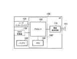
- FIG. 2 is a block diagram of the UE 100.
- the UE 100 includes a plurality of antennas 101, a radio transceiver 110, a user interface 120, a GNSS (Global Navigation Satellite System) receiver 130, a battery 140, a memory 150, and a processor 160.
- the memory 150 corresponds to a storage unit
- the processor 160 corresponds to a control unit.
- the UE 100 may not have the GNSS receiver 130.
- the memory 150 may be integrated with the processor 160, and this set (that is, a chip set) may be used as the processor 160 '.
- the antenna 101 and the wireless transceiver 110 are used for transmitting and receiving wireless signals.
- the radio transceiver 110 converts the baseband signal (transmission signal) output from the processor 160 into a radio signal and transmits it from the antenna 101. Further, the radio transceiver 110 converts a radio signal received by the antenna 101 into a baseband signal (received signal) and outputs the baseband signal to the processor 160.
- the user interface 120 is an interface with a user who owns the UE 100, and includes, for example, a display, a microphone, a speaker, and various buttons.
- the user interface 120 receives an operation from the user and outputs a signal indicating the content of the operation to the processor 160.
- the GNSS receiver 130 receives a GNSS signal and outputs the received signal to the processor 160 in order to obtain location information indicating the geographical location of the UE 100.
- the battery 140 stores power to be supplied to each block of the UE 100.
- the memory 150 stores a program executed by the processor 160 and information used for processing by the processor 160.
- the processor 160 includes a baseband processor that modulates / demodulates and encodes / decodes a baseband signal, and a CPU (Central Processing Unit) that executes programs stored in the memory 150 and performs various processes. .
- the processor 160 may further include a codec that performs encoding / decoding of an audio / video signal.
- the processor 160 executes various processes and various communication protocols described later.
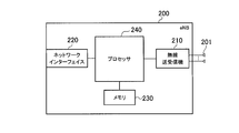
- FIG. 3 is a block diagram of the eNB 200. As illustrated in FIG. 3, the eNB 200 includes an antenna 201, a radio transceiver 210, a network interface 220, a memory 230, and a processor 240.
- the eNB 200 includes an antenna 201, a radio transceiver 210, a network interface 220, a memory 230, and a processor 240.
- the antenna 201 and the wireless transceiver 210 are used for transmitting and receiving wireless signals.
- the radio transceiver 210 converts the baseband signal (transmission signal) output from the processor 240 into a radio signal and transmits it from the antenna 201.
- the radio transceiver 210 converts a radio signal received by the antenna 201 into a baseband signal (received signal) and outputs the baseband signal to the processor 240.
- the network interface 220 is connected to the neighboring eNB 200 via the X2 interface and is connected to the MME / S-GW 300 via the S1 interface.
- the network interface 220 is used for communication performed on the X2 interface and communication performed on the S1 interface.
- the memory 230 stores a program executed by the processor 240 and information used for processing by the processor 240.
- the processor 240 includes a baseband processor that performs modulation / demodulation and encoding / decoding of a baseband signal, and a CPU that executes a program stored in the memory 230 and performs various processes.
- the processor 240 executes various processes and various communication protocols described later.
- FIG. 4 is a protocol stack diagram of a radio interface in the LTE system. As shown in FIG. 4, the radio interface protocol is divided into the first to third layers of the OSI reference model, and the first layer is a physical (PHY) layer.
- the second layer includes a MAC (Medium Access Control) layer, an RLC (Radio Link Control) layer, and a PDCP (Packet Data Convergence Protocol) layer.
- the third layer includes an RRC (Radio Resource Control) layer.
- the physical layer performs encoding / decoding, modulation / demodulation, antenna mapping / demapping, and resource mapping / demapping. Between the physical layer of UE100 and the physical layer of eNB200, user data and a control signal are transmitted via a physical channel.
- the MAC layer performs data priority control, retransmission processing by hybrid ARQ (HARQ), and the like. Between the MAC layer of the UE 100 and the MAC layer of the eNB 200, user data and control signals are transmitted via a transport channel.
- the MAC layer of the eNB 200 includes a scheduler that determines (schedules) uplink / downlink transport formats (transport block size, modulation / coding scheme) and resource blocks allocated to the UE 100.
- the RLC layer transmits data to the RLC layer on the receiving side using the functions of the MAC layer and the physical layer. Between the RLC layer of the UE 100 and the RLC layer of the eNB 200, user data and control signals are transmitted via a logical channel.
- the PDCP layer performs header compression / decompression and encryption / decryption.
- the RRC layer is defined only in the control plane that handles control signals. Control signals (RRC messages) for various settings are transmitted between the RRC layer of the UE 100 and the RRC layer of the eNB 200.
- the RRC layer controls the logical channel, the transport channel, and the physical channel according to establishment, re-establishment, and release of the radio bearer.
- RRC connection When there is a connection (RRC connection) between the RRC of the UE 100 and the RRC of the eNB 200, the UE 100 is in a connection state (RRC connection state). Otherwise, the UE 100 is in an idle state (RRC idle state).
- the NAS (Non-Access Stratum) layer located above the RRC layer performs session management and mobility management.
- FIG. 5 is a configuration diagram of a radio frame used in the LTE system.
- OFDMA Orthogonal Frequency Division Multiple Access
- SC-FDMA Single Carrier Frequency Multiple Access
- the radio frame is composed of 10 subframes arranged in the time direction.
- Each subframe is composed of two slots arranged in the time direction.
- the length of each subframe is 1 ms, and the length of each slot is 0.5 ms.
- Each subframe includes a plurality of resource blocks (RB) in the frequency direction and includes a plurality of symbols in the time direction.
- Each resource block includes a plurality of subcarriers in the frequency direction.
- a resource element is composed of one subcarrier and one symbol.
- frequency resources are configured by resource blocks, and time resources are configured by subframes (or slots).
- the section of the first few symbols of each subframe is an area mainly used as a physical downlink control channel (PDCCH) for transmitting a downlink control signal.
- the remaining part of each subframe is an area that can be used mainly as a physical downlink shared channel (PDSCH) for transmitting downlink user data.
- PDCH physical downlink control channel
- PDSCH physical downlink shared channel
- both ends in the frequency direction in each subframe are regions used mainly as physical uplink control channels (PUCCH) for transmitting uplink control signals.
- the remaining part in each subframe is an area that can be used mainly as a physical uplink shared channel (PUSCH) for transmitting uplink user data.
- PUSCH physical uplink shared channel
- D2D proximity service The outline of the D2D proximity service (D2D ProSe) will be described below.
- the LTE system supports the D2D proximity service.
- the D2D proximity service is a service that enables direct communication without using a network in a synchronous cluster including a plurality of synchronized user terminals.
- the D2D proximity service includes discovery processing for discovering nearby terminals (Discovery) and communication processing for performing direct communication (D2D communication).
- D2D communication is also referred to as direct communication.
- a scenario in which all UEs 100 forming a synchronous cluster are located in the cell coverage is referred to as “in network coverage or in coverage (InC)”.
- a scenario in which all UEs 100 forming a synchronous cluster are located outside cell coverage is referred to as “out of network coverage or out of coverage (OoC)”.
- a scenario in which some UEs 100 in the synchronization cluster are located within the cell coverage and the remaining UEs 100 are located outside the cell coverage is referred to as “partial network coverage or partial coverage”.
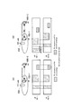
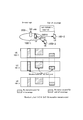
- FIG. 6 is a diagram for explaining scenarios within and outside the network coverage.
- the eNB 200 becomes the D2D synchronization source.
- the D2D synchronization source refers to a node (Synchronization source) that transmits a D2D synchronization signal (D2DSS).
- the D2D asynchronous source refers to a node (Un-synchronization source) that does not transmit the D2D synchronization signal and synchronizes with the D2D synchronization source.
- the eNB 200 that is the D2D synchronization source transmits D2D resource information (SA: Scheduling Assignment) indicating a radio resource that can be used for the D2D proximity service by a broadcast signal.
- the D2D resource information may be information indicating a Discovery radio resource (hereinafter referred to as “Discovery resource”) and a D2D communication radio resource (hereinafter referred to as “Communication resource”).
- the UE 100-1 which is the D2D asynchronous source, performs Discovery and D2D communication based on the D2D resource information received from the eNB 200.
- a predetermined UE 100 (UE 100-2 in FIG. 6) becomes the D2D synchronization source.
- the UE 100-2 that is the D2D synchronization source transmits D2D resource information using a broadcast signal.
- the UE 100-3 that is the D2D asynchronous source performs Discovery and D2D communication based on the D2D resource information received from the UE 100-2.
- the D2D resource information is notified in an SA reception resource pool (SA reception resource pool) that is a predetermined radio resource area.
- SA reception resource pool SA reception resource pool
- information regarding the SA reception resource pool is set in advance in the UE 100 so that the UE 100 can receive D2D resource information even outside the network coverage.
- the UE 100 includes a storage unit (memory 150) that stores information related to the SA reception resource pool, a transmission unit (such as the processor 160 and the radio transceiver 110) that transmits a synchronization signal for the D2D proximity service, And a control unit (processor 160) that monitors the reception status of the synchronization signal and the reception status of the control signal in the control radio resource.
- a storage unit memory 150
- a transmission unit such as the processor 160 and the radio transceiver 110
- a control unit that monitors the reception status of the synchronization signal and the reception status of the control signal in the control radio resource.
- the UE 100 may receive D2D resource information in a preset SA resource pool, it is necessary to monitor all the preset SA resource pools.
- the UE 100-1 and the UE 100-2 are configured so that the SA resource pool for network coverage (Rx resource pool for in-coverage) and the SA resource pool for outside network coverage (Rx) Monitor resource pool for out-of-coverage.
- the UE 100-1 and the UE 100-2 can receive the D2D resource information when the D2D resource information is specified in the SA resource pool.
- the UE 100 does not monitor the SA resource pool when it is not synchronized or when there is a possibility that it is not synchronized.
- the UE 100 can reduce power consumption by not monitoring the SA resource pool.
- the UE 100 when the UE 100 located outside the network coverage does not receive the D2D synchronization signal from the other UE 100 and the UE 100 does not transmit the D2D synchronization signal, the UE 100 Do not monitor the resource pool. Thereby, power consumption can be reduced. Note that the UE 100 periodically monitors the reception status of the synchronization signal, and checks whether there is a UE 100 that performs the D2D service in the vicinity.
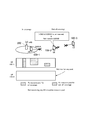
- FIG. 8 shows the operation of the UE 100 according to the present embodiment.
- the UE 100-2 located outside the network coverage (OoC) has not received the D2D synchronization signal from the UE 100-1 located within the network coverage (InC). Also, the UE 100-2 has not received the D2D synchronization signal from the UE 100-3 located outside the network coverage (OoC). Furthermore, the UE 100-2 does not transmit the D2D synchronization signal. In such a case, the UE 100-2 does not monitor the SA resource pool for network coverage and the SA resource pool for outside network coverage.
- the UE 100 is located outside the network coverage.
- the UE 100 receives the D2D synchronization signal from other UEs 100 located outside the network coverage, and / or the UE 100 transmits the D2D synchronization signal.
- the UE 100 monitors only the SA resource pool for outside the network coverage in the SA resource pool.
- the UE 100 Since the UE 100 is synchronized with or highly likely to be synchronized with other UEs 100 outside the network coverage, the UE resource pool outside the network coverage is monitored. On the other hand, it is not synchronized with other UEs in the network coverage. In this case, since it is unlikely that the designation of the resource for D2D from another UE 100 in the network coverage can be received, the SA resource in the network coverage is not monitored.
- D2D synchronization signal whether another UE 100 is located within the network coverage or outside the network coverage may be notified using the D2D synchronization signal. In-coverage and out-of-coverage information is included in the D2D synchronization signal. Alternatively, a method such as using different sync signal formats within and outside the coverage can be considered.
- FIG. 9 shows the operation of the UE 100 according to the present embodiment.
- FIG. 9 shows a case where the UE 100-2 located outside the network coverage (OoC) has not received the D2D synchronization signal from the UE 100-1 located within the network coverage (InC), and It is a figure showing the monitoring condition of SA resource pool in the case of synchronizing with UE100-3 located in the outside of network coverage (OoC).
- the UE 100-2 and the UE 100-3 are synchronized with each other when at least one of the UE 100-2 and the UE 100-3 transmits a synchronization signal for D2D.
- the UE 100-2 is not synchronized with the UE 100-1 because it does not receive the synchronization signal for D2D of the UE 100-1.
- the UE 100-2 monitors the SA resource pool outside the network coverage that can receive the designation of the D2D resource by synchronizing with the UE 100-3.
- the SA resource pool for network coverage is not monitored.
- the UE 100 when the UE 100 receives a synchronization signal from a plurality of other UEs located outside the network coverage, the UE 100 selects one other UE.
- the UE 100 may stop transmitting the D2D synchronization signal.
- the UE 100-2 when the UE 100-2 is located outside the network coverage, the UE 100-2 receives the D2D synchronization signal from the UE 100-1 located within the network coverage. In this case, the UE 100-2 monitors the reception status of both the SA resource pool for network coverage and the SA resource pool for outside network coverage.
- the UE 100-2 and the UE 100-3 are synchronized as a result.
- the UE 100-2 can reliably receive the SA resource pool outside the network coverage even if the D2D resource is designated from the UE 100-3.
- the UE 100-2 receives the synchronization signal for D2D from the other UEs 100-1 located in the coverage area, the UE 100-2 only has to have the SA resource pool for the network coverage area.
- the reception status of the SA resource pool for outside the network coverage is monitored.
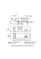
- FIG. 10 shows the operation of the UE 100 according to the present embodiment.
- the UE 100-2 located outside the network coverage receives the D2D synchronization signal from the UE 100-1 located within the network coverage.
- the UE 100-2 monitors the reception status of both the SA resource pool for network coverage and the SA resource pool for network coverage. As described above, this is because the UE 100-3 outside the network coverage may receive the D2D synchronization signal from the UE 100-1 in the same manner as the UE 100-2.
- the UE 100-2 located outside the network coverage receives an instruction to specify a part of the SA resource pool for the network coverage from the UE 100-1 located within the network coverage
- the UE 100-2 Monitors the reception status of a part of the notified SA resource pool for the network coverage and the SA resource pool for the outside of the network coverage.
- the SA resource pool within the network coverage may be specified using a D2D synchronization signal or PD2DSCH (Physical D2D Shared Channel).
- PD2DSCH Physical D2D Shared Channel
- the UE 100-2 located outside the network coverage monitors the reception status of the SA resource pool A (Rx resource pool for in-coverage A) for network coverage from the UE 100-1 located within the network coverage. Receive instructions (Indicating pool A). Then, the UE 100-2 performs reception monitoring of the SA resource pool A within the network coverage and the SA resource pool outside the network coverage. The UE 100-2 does not monitor reception of the SA resource pool B within the network coverage.
- SA resource pool A Rx resource pool for in-coverage A
- Receive instructions Indicating pool A
- the UE 100-2 performs reception monitoring of the SA resource pool A within the network coverage and the SA resource pool outside the network coverage.
- the UE 100-2 does not monitor reception of the SA resource pool B within the network coverage.
- the UE 100 uses the D2D synchronization signal transmitted by one UE 100 among the plurality of other UEs 100 in the network coverage. Synchronize.
- the UE 100 may determine another UE 100 to be synchronized using the signal strength of the D2D synchronization signal, the priority of the D2D synchronization signal, the size of the radio resource for D2D control, and the like.
- the UE 100-2 outside the network coverage receives the D2D synchronization signal transmitted by the other UE 100-1 within the network coverage
- the UE 100-2 receives the synchronization signal from the other UE 100-3 outside the network coverage.
- the UE 100-2 may generate the D2D synchronization signal with reference to the D2D synchronization signal transmitted by the UE 100-1, and transmit the generated D2D synchronization signal to the UE 100-3.
- the UE 100-2 generates the synchronization signal and transmits the generated synchronization signal based on the remaining battery level of the UE 100-2. You may decide whether to do it.
- the operation when the UE 100 monitors the reception status of the D2D SA resource pool is described. However, the UE 100 discovers another D2D UE (D2D Discovery). You may apply.
- the LTE system has been described as an example of the mobile communication system.
- the present invention is not limited to the LTE system, and the present invention may be applied to a system other than the LTE system.
- the present invention is useful in the communication field.
Abstract
Description
第1実施形態に係るユーザ端末は、ネットワークを介さない直接的な端末間通信を可能とするD2D近傍サービスをサポートするユーザ端末であって、前記D2D近傍サービス用の制御信号を受信するための制御用無線リソースに関する情報を記憶する記憶部と、前記D2D近傍サービス用の同期信号を送信する送信部と、他のユーザ端末からの、前記同期信号の受信状況と、前記制御用無線リソースにおける前記制御信号の受信状況の監視を行う制御部と、を有し、ネットワークカバレッジ外において、前記制御部が、前記他のユーザ端末から、前記同期信号を受信しておらず、かつ、前記送信部が、前記同期信号を送信していない場合、前記制御部は、前記制御用無線リソースの前記受信状況を監視せず、かつ、前記同期信号の前記受信状況を定期的に監視する。 [Outline of Embodiment]
The user terminal according to the first embodiment is a user terminal that supports a D2D proximity service that enables direct inter-terminal communication without using a network, and controls for receiving the control signal for the D2D proximity service A storage unit that stores information on radio resources for transmission, a transmission unit that transmits synchronization signals for the D2D proximity service, reception status of the synchronization signals from other user terminals, and the control in the radio resources for control A control unit that monitors the reception status of the signal, outside the network coverage, the control unit has not received the synchronization signal from the other user terminal, and the transmission unit, When the synchronization signal is not transmitted, the control unit does not monitor the reception status of the control radio resource and receives the synchronization signal. Regularly to monitor the situation.
以下において、本発明をLTEシステムに適用する場合の実施形態を説明する。 [First Embodiment]
In the following, an embodiment when the present invention is applied to an LTE system will be described.
図1は、第1実施形態に係るLTEシステムの構成図である。図1に示すように、第1実施形態に係るLTEシステムは、UE(User Equipment)100、E-UTRAN(Evolved-UMTS Terrestrial Radio Access Network)10、及びEPC(Evolved Packet Core)20を備える。 (System configuration)
FIG. 1 is a configuration diagram of an LTE system according to the first embodiment. As shown in FIG. 1, the LTE system according to the first embodiment includes a UE (User Equipment) 100, an E-UTRAN (Evolved-UMTS Terrestrial Radio Access Network) 10, and an EPC (Evolved Packet Core) 20.
以下において、D2D近傍サービス(D2D ProSe)の概要について説明する。 (D2D proximity service)
The outline of the D2D proximity service (D2D ProSe) will be described below.
次に本発明に係る第2実施形態について説明する。第1実施形態と共通する部分については説明を省略し、差分についてのみ説明する。 [Second Embodiment]
Next, a second embodiment according to the present invention will be described. Description of parts common to the first embodiment will be omitted, and only differences will be described.
次に本発明に係る第2実施形態について説明する。第1実施形態と共通する部分については説明を省略し、差分についてのみ説明する。 [Third Embodiment]
Next, a second embodiment according to the present invention will be described. Description of parts common to the first embodiment will be omitted, and only differences will be described.
なお、第1乃至第3実施形態では、UE100が、D2D用SAリソースプールの受信状況を監視する際の動作について記載したが、UE100が、他のD2D用UEを発見する動作(D2D Discovery)に適用してもよい。 [Other Embodiments]
In the first to third embodiments, the operation when the
Claims (11)
- ネットワークを介さない直接的な端末間通信を可能とするD2D近傍サービスをサポートするユーザ端末であって、
ネットワークカバレッジ外において、複数の他のユーザ端末が送信するD2D用同期信号を受信する場合に、前記複数の他のユーザ端末のうちの1つをD2D同期元として選択し、前記D2D同期元が送信するD2D用同期信号に同期する制御部を備える
ユーザ端末。 A user terminal that supports a D2D proximity service that enables direct terminal-to-terminal communication without a network,
When receiving a D2D synchronization signal transmitted by a plurality of other user terminals outside the network coverage, one of the plurality of other user terminals is selected as a D2D synchronization source, and the D2D synchronization source transmits A user terminal comprising a control unit synchronized with the D2D synchronization signal. - 前記複数の他のユーザ端末は、ネットワークカバレッジ外のユーザ端末である
請求項1に記載のユーザ端末。 The user terminal according to claim 1, wherein the plurality of other user terminals are user terminals out of network coverage. - 前記制御部は、ネットワークカバレッジ外において、前記ユーザ端末が所定のD2D用同期信号を送信している際に、他のユーザ端末を前記D2D同期元として選択したことに応じて、前記所定のD2D用同期信号の送信を停止する
請求項1に記載のユーザ端末。 When the user terminal is transmitting a predetermined D2D synchronization signal outside the network coverage, the control unit selects the other user terminal as the D2D synchronization source, and then selects the predetermined D2D The user terminal according to claim 1, wherein transmission of the synchronization signal is stopped. - 前記複数の他のユーザ端末は、ネットワークカバレッジ内のユーザ端末である
請求項1に記載のユーザ端末。 The user terminal according to claim 1, wherein the plurality of other user terminals are user terminals within network coverage. - 前記制御部は、前記複数の他のユーザ端末のそれぞれについての信号強度及び優先度の少なくとも一方に基づいて、前記D2D同期元を選択する
請求項1に記載のユーザ端末。 The user terminal according to claim 1, wherein the control unit selects the D2D synchronization source based on at least one of signal strength and priority for each of the plurality of other user terminals. - 前記制御部は、ネットワークカバレッジ内の他のユーザ端末が送信するD2D用同期信号を参照してD2D用同期信号を生成し、生成したD2D用同期信号を送信する
請求項1に記載のユーザ端末。 The user terminal according to claim 1, wherein the control unit generates a D2D synchronization signal with reference to a D2D synchronization signal transmitted by another user terminal in the network coverage, and transmits the generated D2D synchronization signal. - 前記制御部は、ネットワークカバレッジ外において、他のユーザ端末から前記ユーザ端末がD2D用同期信号を受信しておらず、かつ、前記ユーザ端末がD2D用同期信号を送信していない場合に、D2D通信用リソースプールにおける受信状況の監視を省略する
請求項1に記載のユーザ端末。 The control unit performs D2D communication when the user terminal has not received the D2D synchronization signal from another user terminal and the user terminal has not transmitted the D2D synchronization signal outside the network coverage. The user terminal according to claim 1, wherein monitoring of reception status in the resource pool is omitted. - D2D通信用リソースプールが、ネットワークカバレッジ内用の第1無線リソースと、ネットワークカバレッジ外用の第2無線リソースと、に分かれており、
前記制御部は、ネットワークカバレッジ内の他のユーザ端末が送信するD2D用同期信号を受信しておらず、かつ、所定の条件が満たされた場合に、前記D2D通信用リソースプールのうち前記第2無線リソースにおける受信状況のみを監視し、
前記所定の条件は、ネットワークカバレッジ外の他のユーザ端末から前記ユーザ端末がD2D用同期信号を受信したこと、及び、前記ユーザ端末がD2D用同期信号を送信していること、のうち少なくとも一方である
請求項1に記載のユーザ端末。 The resource pool for D2D communication is divided into a first radio resource for network coverage and a second radio resource for outside network coverage,
The control unit does not receive the D2D synchronization signal transmitted by another user terminal in the network coverage, and satisfies a predetermined condition, the second of the D2D communication resource pools. Monitor only the reception status of radio resources,
The predetermined condition is at least one of receiving the D2D synchronization signal from another user terminal outside the network coverage and transmitting the D2D synchronization signal from the user terminal. The user terminal according to claim 1. - D2D通信用リソースプールが、ネットワークカバレッジ内用の第1無線リソースと、ネットワークカバレッジ外用の第2無線リソースと、に分かれており、
前記制御部は、ネットワークカバレッジ内の他のユーザ端末から前記ユーザ端末がD2D用同期信号を受信した場合に、前記第1無線リソース及び前記第2無線リソースのそれぞれにおける受信状況を監視する
請求項1に記載のユーザ端末。 The resource pool for D2D communication is divided into a first radio resource for network coverage and a second radio resource for outside network coverage,
The control unit monitors a reception status of each of the first radio resource and the second radio resource when the user terminal receives a synchronization signal for D2D from another user terminal in the network coverage. The user terminal described in 1. - 前記制御部は、ネットワークカバレッジ内の他のユーザ端末から前記第1無線リソースのうち一部の無線リソースが指定された場合に、前記一部の無線リソースにおける受信状況のみを監視する
請求項9に記載のユーザ端末。 The control unit monitors only the reception status of the part of the radio resources when a part of the radio resources of the first radio resource is designated from another user terminal in the network coverage. The described user terminal. - ネットワークを介さない直接的な端末間通信を可能とするD2D近傍サービスをサポートするユーザ端末における通信制御方法であって、
ネットワークカバレッジ外において、複数の他のユーザ端末が送信するD2D用同期信号を受信する場合に、前記複数の他のユーザ端末のうちの1つをD2D同期元として選択し、前記D2D同期元が送信するD2D用同期信号に同期する
ことを含む通信制御方法。 A communication control method in a user terminal that supports a D2D proximity service that enables direct inter-terminal communication without using a network,
When receiving a D2D synchronization signal transmitted by a plurality of other user terminals outside the network coverage, one of the plurality of other user terminals is selected as a D2D synchronization source, and the D2D synchronization source transmits A communication control method including synchronizing with a synchronization signal for D2D.
Priority Applications (3)
| Application Number | Priority Date | Filing Date | Title |
|---|---|---|---|
| JP2016517930A JP6130592B2 (en) | 2014-05-09 | 2015-05-08 | User terminal and device |
| EP15789247.2A EP3142459A4 (en) | 2014-05-09 | 2015-05-08 | User terminal and communication control method |
| US15/047,948 US10098169B2 (en) | 2014-05-09 | 2016-02-19 | User terminal and communication control method |
Applications Claiming Priority (2)
| Application Number | Priority Date | Filing Date | Title |
|---|---|---|---|
| US201461990900P | 2014-05-09 | 2014-05-09 | |
| US61/990,900 | 2014-05-09 |
Related Child Applications (1)
| Application Number | Title | Priority Date | Filing Date |
|---|---|---|---|
| US15/047,948 Continuation US10098169B2 (en) | 2014-05-09 | 2016-02-19 | User terminal and communication control method |
Publications (1)
| Publication Number | Publication Date |
|---|---|
| WO2015170727A1 true WO2015170727A1 (en) | 2015-11-12 |
Family
ID=54392576
Family Applications (1)
| Application Number | Title | Priority Date | Filing Date |
|---|---|---|---|
| PCT/JP2015/063259 WO2015170727A1 (en) | 2014-05-09 | 2015-05-08 | User terminal and communication control method |
Country Status (4)
| Country | Link |
|---|---|
| US (1) | US10098169B2 (en) |
| EP (1) | EP3142459A4 (en) |
| JP (1) | JP6130592B2 (en) |
| WO (1) | WO2015170727A1 (en) |
Cited By (1)
| Publication number | Priority date | Publication date | Assignee | Title |
|---|---|---|---|---|
| WO2018173523A1 (en) * | 2017-03-24 | 2018-09-27 | ソニー株式会社 | Communication device and terminal device |
Families Citing this family (1)
| Publication number | Priority date | Publication date | Assignee | Title |
|---|---|---|---|---|
| JP6328246B2 (en) * | 2013-12-20 | 2018-05-23 | 京セラ株式会社 | Inter-device (D2D) subframe with cell identifier |
Citations (4)
| Publication number | Priority date | Publication date | Assignee | Title |
|---|---|---|---|---|
| JP2011176549A (en) * | 2010-02-24 | 2011-09-08 | Hitachi Kokusai Electric Inc | Wireless communication system |
| JP2013176137A (en) * | 2013-04-24 | 2013-09-05 | Toshiba Corp | Radio apparatus and communication method |
| WO2014051126A1 (en) * | 2012-09-27 | 2014-04-03 | 京セラ株式会社 | Mobile communication system, user terminal, processor, and base station |
| WO2015015924A1 (en) * | 2013-07-31 | 2015-02-05 | ソニー株式会社 | Terminal device and information processing device |
Family Cites Families (5)
| Publication number | Priority date | Publication date | Assignee | Title |
|---|---|---|---|---|
| GB2472596A (en) * | 2009-08-11 | 2011-02-16 | Nec Corp | A system to coordinate the changing of handover/cell reselection parameters between e-utran and non e-utran rats to reduce repeated handover /cell reselection |
| EP2665325B1 (en) * | 2012-05-15 | 2014-08-13 | Telefonaktiebolaget L M Ericsson (publ) | Radio link management for network assisted device-to-device communication |
| US11496948B2 (en) * | 2012-10-19 | 2022-11-08 | Samsung Electronics Co., Ltd. | System and method for ad-hoc/network assisted device discovery protocol for device to device communications |
| US9654960B2 (en) * | 2013-05-31 | 2017-05-16 | Qualcomm Incorporated | Server-assisted device-to-device discovery and connection |
| US9843989B2 (en) * | 2014-02-10 | 2017-12-12 | Nokia Solutions And Networks Oy | Uniform UE initialization procedure for both in-coverage and out-of-coverage D2D communications |
-
2015
- 2015-05-08 EP EP15789247.2A patent/EP3142459A4/en not_active Ceased
- 2015-05-08 WO PCT/JP2015/063259 patent/WO2015170727A1/en active Application Filing
- 2015-05-08 JP JP2016517930A patent/JP6130592B2/en active Active
-
2016
- 2016-02-19 US US15/047,948 patent/US10098169B2/en active Active
Patent Citations (4)
| Publication number | Priority date | Publication date | Assignee | Title |
|---|---|---|---|---|
| JP2011176549A (en) * | 2010-02-24 | 2011-09-08 | Hitachi Kokusai Electric Inc | Wireless communication system |
| WO2014051126A1 (en) * | 2012-09-27 | 2014-04-03 | 京セラ株式会社 | Mobile communication system, user terminal, processor, and base station |
| JP2013176137A (en) * | 2013-04-24 | 2013-09-05 | Toshiba Corp | Radio apparatus and communication method |
| WO2015015924A1 (en) * | 2013-07-31 | 2015-02-05 | ソニー株式会社 | Terminal device and information processing device |
Non-Patent Citations (2)
| Title |
|---|
| NOKIA ET AL.: "Synchronization procedure for D2D communication and discovery", 3GPP TSG-RAN WG1#77 RL-142453, 23 May 2014 (2014-05-23), XP050788048, Retrieved from the Internet <URL:http://www.3gpp.org/ftp/tsg_ran/WG1_RL1/TSGR1_77/Docs//R1-142453.zip> * |
| See also references of EP3142459A4 * |
Cited By (2)
| Publication number | Priority date | Publication date | Assignee | Title |
|---|---|---|---|---|
| WO2018173523A1 (en) * | 2017-03-24 | 2018-09-27 | ソニー株式会社 | Communication device and terminal device |
| US11116021B2 (en) | 2017-03-24 | 2021-09-07 | Sony Corporation | Communication apparatus and terminal apparatus |
Also Published As
| Publication number | Publication date |
|---|---|
| EP3142459A1 (en) | 2017-03-15 |
| JP6130592B2 (en) | 2017-05-17 |
| EP3142459A4 (en) | 2017-11-29 |
| US10098169B2 (en) | 2018-10-09 |
| JPWO2015170727A1 (en) | 2017-04-20 |
| US20160174279A1 (en) | 2016-06-16 |
Similar Documents
| Publication | Publication Date | Title |
|---|---|---|
| JP6142082B2 (en) | User terminal, processor, and base station | |
| JP6654136B2 (en) | Receiving terminal and transmitting terminal | |
| JP6499166B2 (en) | Communication control method, user terminal and base station | |
| WO2016021700A1 (en) | Communication control method and user terminal | |
| JP6174141B2 (en) | Communication control method and base station | |
| JPWO2015141847A1 (en) | Communication control method and base station | |
| JP6130592B2 (en) | User terminal and device | |
| JP6200078B2 (en) | User terminal, processor and method | |
| JP6515083B2 (en) | User terminal and communication control method | |
| JP6398032B2 (en) | Mobile communication system, user terminal, base station, and processor | |
| JPWO2016163431A1 (en) | User terminal and control method | |
| WO2015005244A1 (en) | User terminal, network device, and processor | |
| WO2014157393A1 (en) | Mobile communication system, base station, and user terminal | |
| WO2014129456A1 (en) | Communication control method, base station, and user terminal | |
| JP6106286B2 (en) | User terminal and processor | |
| JP6619730B2 (en) | Mobile communication system, user terminal and processor | |
| JP2014220777A (en) | Communication control method and cellular base station |
Legal Events
| Date | Code | Title | Description |
|---|---|---|---|
| 121 | Ep: the epo has been informed by wipo that ep was designated in this application |
Ref document number: 15789247 Country of ref document: EP Kind code of ref document: A1 |
|
| ENP | Entry into the national phase |
Ref document number: 2016517930 Country of ref document: JP Kind code of ref document: A |
|
| REEP | Request for entry into the european phase |
Ref document number: 2015789247 Country of ref document: EP |
|
| WWE | Wipo information: entry into national phase |
Ref document number: 2015789247 Country of ref document: EP |
|
| NENP | Non-entry into the national phase |
Ref country code: DE |