WO2015165526A1 - Improved water drainage assembly for use in a refrigeration appliance - Google Patents
Improved water drainage assembly for use in a refrigeration appliance Download PDFInfo
- Publication number
- WO2015165526A1 WO2015165526A1 PCT/EP2014/058841 EP2014058841W WO2015165526A1 WO 2015165526 A1 WO2015165526 A1 WO 2015165526A1 EP 2014058841 W EP2014058841 W EP 2014058841W WO 2015165526 A1 WO2015165526 A1 WO 2015165526A1
- Authority
- WO
- WIPO (PCT)
- Prior art keywords
- water drainage
- mounting seat
- sided
- drainage assembly
- wall
- Prior art date
- Legal status (The legal status is an assumption and is not a legal conclusion. Google has not performed a legal analysis and makes no representation as to the accuracy of the status listed.)
- Ceased
Links
Images





Classifications
-
- F—MECHANICAL ENGINEERING; LIGHTING; HEATING; WEAPONS; BLASTING
- F25—REFRIGERATION OR COOLING; COMBINED HEATING AND REFRIGERATION SYSTEMS; HEAT PUMP SYSTEMS; MANUFACTURE OR STORAGE OF ICE; LIQUEFACTION SOLIDIFICATION OF GASES
- F25D—REFRIGERATORS; COLD ROOMS; ICE-BOXES; COOLING OR FREEZING APPARATUS NOT OTHERWISE PROVIDED FOR
- F25D21/00—Defrosting; Preventing frosting; Removing condensed or defrost water
- F25D21/14—Collecting or removing condensed and defrost water; Drip trays
-
- F—MECHANICAL ENGINEERING; LIGHTING; HEATING; WEAPONS; BLASTING
- F25—REFRIGERATION OR COOLING; COMBINED HEATING AND REFRIGERATION SYSTEMS; HEAT PUMP SYSTEMS; MANUFACTURE OR STORAGE OF ICE; LIQUEFACTION SOLIDIFICATION OF GASES
- F25D—REFRIGERATORS; COLD ROOMS; ICE-BOXES; COOLING OR FREEZING APPARATUS NOT OTHERWISE PROVIDED FOR
- F25D21/00—Defrosting; Preventing frosting; Removing condensed or defrost water
-
- F—MECHANICAL ENGINEERING; LIGHTING; HEATING; WEAPONS; BLASTING
- F25—REFRIGERATION OR COOLING; COMBINED HEATING AND REFRIGERATION SYSTEMS; HEAT PUMP SYSTEMS; MANUFACTURE OR STORAGE OF ICE; LIQUEFACTION SOLIDIFICATION OF GASES
- F25D—REFRIGERATORS; COLD ROOMS; ICE-BOXES; COOLING OR FREEZING APPARATUS NOT OTHERWISE PROVIDED FOR
- F25D23/00—General constructional features
- F25D23/06—Walls
- F25D23/061—Walls with conduit means
-
- F—MECHANICAL ENGINEERING; LIGHTING; HEATING; WEAPONS; BLASTING
- F24—HEATING; RANGES; VENTILATING
- F24F—AIR-CONDITIONING; AIR-HUMIDIFICATION; VENTILATION; USE OF AIR CURRENTS FOR SCREENING
- F24F13/00—Details common to, or for air-conditioning, air-humidification, ventilation or use of air currents for screening
- F24F13/22—Means for preventing condensation or evacuating condensate
- F24F13/222—Means for preventing condensation or evacuating condensate for evacuating condensate
- F24F2013/227—Condensate pipe for drainage of condensate from the evaporator
-
- F—MECHANICAL ENGINEERING; LIGHTING; HEATING; WEAPONS; BLASTING
- F25—REFRIGERATION OR COOLING; COMBINED HEATING AND REFRIGERATION SYSTEMS; HEAT PUMP SYSTEMS; MANUFACTURE OR STORAGE OF ICE; LIQUEFACTION SOLIDIFICATION OF GASES
- F25D—REFRIGERATORS; COLD ROOMS; ICE-BOXES; COOLING OR FREEZING APPARATUS NOT OTHERWISE PROVIDED FOR
- F25D2321/00—Details or arrangements for defrosting; Preventing frosting; Removing condensed or defrost water, not provided for in other groups of this subclass
- F25D2321/14—Collecting condense or defrost water; Removing condense or defrost water
Definitions
- the present invention relates to a water drainage assembly for use in a refrigeration appliance, in particular a domestic refrigerator.
- a conventional domestic refrigerator has a water drainage facility for draining defrost water which is formed inside an inner case to an outside.
- the water drainage facility usually has a drainage hose which is mounted to a drainage outlet of the inner case by utilizing silicone hot melt adhesives.
- a problem with the assembly process involving the silicone hot melt adhesives is that in the event of using an excessive amount of adhesive silicone, the drainage hose may get clogged, and in the event of using an insufficient mount of adhesive silicone, the junction between the drainage hose and the drainage outlet may have leak.
- the water drainage facility will not function properly due to clogging.
- the defrost water in the domestic refrigerator starts to leak into the kitchen due to the manufacturing errors.
- the customer returns such domestic refrigerators to a customer service for inspection. This reduces consumer satisfaction.
- EP 2 476 981 A2 discloses a drain hose assembly for use in a refrigerator and a refrigerator having the same.
- An objective of the present invention is to provide a water drainage assembly for use in refrigeration appliance and a refrigeration appliance having the same which overcomes the aforementioned drawbacks of the prior art and which enables a cost-effective, easy and reliable assembly process.
- a rear outer wall of the outer case has a vertical planar portion into which an opening is formed.
- the vertical planar portion extends in a lateral direction which is perpendicular to the lateral outer walls of the outer case.
- a rear inner wall of the inner case has a curved portion into which the drainage outlet is formed. The curved portion extends straight along said lateral direction. The opening lies lower than the drainage outlet.
- the water drainage assembly of the present invention comprises a water drainage apparatus which has an upper mounting seat and a lower mounting seat which are formed on opposing ends of a main body thereof.
- the lower mounting seat form-fittingly abuts against the vertical planar portion.
- the upper mounting seat form-fittingly abuts against the curved portion.
- the water drainage apparatus further comprises an inclined channel formed into the main body so as to fluidly connect the opening with the drainage outlet.
- the water drainage assembly further comprises a plurality of bonding tapes for sealing an interface between the vertical planar portion and the lower mounting seat and an interface between the curved portion and the upper mounting seat respectively.
- the water drainage assembly comprises a double-sided first bonding tape which is to be arranged between a lower mounting seat and the vertical planar portion so as to bond them together.
- the first bonding tape has a through-hole for allowing throughflow of drainage water.
- the water drainage assembly comprises a double-sided second bonding tape to be arranged between an inner surface of the upper mounting seat and the curved portion to bond them together.
- the second bonding tape has a through-hole or cut portion for allowing throughflow of drainage water.
- the water drainage assembly comprises a single-sided third bonding tape to be arranged on a rear surface of the upper mounting seat and on a periphery of the curved portion to bond them together.
- the single-sided third bonding tape has a cut portion to encompass the body of the water drainage apparatus.
- the water drainage assembly comprises in addition to the single-sided third bonding tape, a double-sided fourth bonding tape to be arranged between a lower part of the inner surface of the upper mounting seat and the curved portion to bond them together.
- the fourth bonding tape partly overlaps in a stacking direction the third bonding tape including a cut portion thereof.
- the refrigeration appliance comprises cured foam material that encloses the water drainage assembly.
- the water drainage apparatus can be stably abutted against the vertical planar portion and the curved portions and simultaneously fixed to its designated position by utilizing the bonding tapes which also seal the interfaces to prevent intrusion of curing foam material.
- the use of silicone hot melt adhesive has been obviated. Thereby, a risk of clogging of the drainage outlet or any other component parts has been eliminated. The overall rate of waste production and manufacturing errors has been effectively reduced.
- the water drainage assembly of the present invention is cost-effective and easy to install.
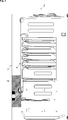
- Figure 1 – is a schematic exploded partial perspective side view of a refrigeration appliance having the water drainage assembly according to an embodiment of the present invention
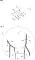
- Figure 2 – is a schematic enlarged view of the detail A of Fig. 1;
- Figure 3 – is a schematic vertical cross sectional partial view of the refrigeration appliance having the water drainage assembly according to an embodiment of the present invention
- Figure 4 – is a schematic perspective view of a water drainage apparatus of the water drainage assembly according to an embodiment of the present invention.
- Figure 5 – is a schematic vertical cross sectional view of the water drainage apparatus of Fig. 4, take along the line B-B;
- Figure 6 – is a schematic enlarged view of the detail C of Fig. 5;
- Figure 7 – is a schematic perspective view of the water drainage assembly according to an embodiment of the present invention.
- Figure 8 – is a schematic perspective view of the water drainage assembly according to another embodiment of the present invention.
- Figure 9 – is a schematic perspective view of the water drainage assembly according to another embodiment of the present invention.
- the water drainage assembly (1) is suitable for use in a refrigeration appliance (2), in particular a domestic refrigerator (Figs. 1 to 3).
- the refrigeration appliance (2) comprises an outer case (3) and an inner case (6).
- the outer case (3) comprises two mutually opposing lateral outer walls (not shown) and a rear outer wall (4).
- the inner case (6) comprises a rear inner wall (7) and a drainage outlet (8) (Figs. 1 to 3).
- the refrigeration appliance (2) of the present invention comprises an opening (5) which is is formed into a vertical planar portion (4a) of the rear outer wall (4).
- the vertical planar portion (4a) extends in a lateral direction which is perpendicular to the lateral outer walls.
- the drainage outlet (8) is formed into a curved portion (7a) of the rear inner wall (7).
- the curved portion (7a) extends straight along said lateral direction.
- the opening (5) lies lower than the drainage outlet (8).
- the refrigeration appliance (2) of the present invention further comprises a water drainage assembly (1) which is mounted between the vertical planar portion (4a) and curved portion (7a) (Figs. 1 to 3).
- the water drainage assembly (1) of the present invention comprises a water drainage apparatus (9) which includes a main body (10) having an upper mounting seat (11) and a lower mounting seat (12) which are formed on opposing ends of the main body (10).
- the lower mounting seat (12) is configured to form-fittingly abut against the vertical planar portion (4a) whereas the upper mounting seat (11) is configured to form-fittingly abut against the curved portion (7a).
- An inclined channel (13) is formed into the main body (10).
- the channel (13) is configured to fluidly connect the opening (5) with the drainage outlet (8).
- the water drainage assembly (1) of the present invention further comprises a plurality of bonding tapes (14) for sealing an interface between the vertical planar portion (4a) and the lower mounting seat (12), and an interface between the curved portion (7a) and the upper mounting seat (11) respectively (Figs. 1 to 9).
- the refrigeration appliance (2) comprises cured foam material (18) between the rear outer wall (4) and the rear inner wall (7).
- the foam material (18) encloses the water drainage assembly (1) (Fig. 3).
- a conduit (15) is provided inside the channel (13).
- the conduit (15) has a lower end (15a) and an upper end (15b).
- the lower end (15a) of the conduit (15) is configured to attach to a drainage-hose (not shown) whereas an upper end (15b) of the conduit (15) is configured to allow the drainage outlet (8) to penetrate into the conduit (15) (Figs. 4 to 6).
- conduit (15) is coaxially provided inside the channel (13) (Fig. 5).
- the bonding tapes (14) include a double-sided first bonding tape (14a) which is provided with a through-hole (16).
- the double-sided first bonding tape (14a) has a size and shape which is configured to adhere to the lower mounting seat (12) and to the vertical planar portion (4a).
- the channel (13) fluidly connects the opening (5) with the drainage outlet (8) through said through-hole (16) (Figs. 7 to 9).
- the bonding tapes (14) further include a double-sided second bonding tape (14b) which has a cut portion (17a) defining a fluid passage.
- the double-sided second bonding tape (14b) has a size and shape which is configured to adhere to an inner surface (11a) of the upper mounting seat (11) and to the curved portion (7a).
- the channel (13) fluidly connects the opening (5) with the drainage outlet (8) through said fluid passage (Fig. 7).
- the bonding tapes (14) further include a single-sided third bonding tape (14c).
- the single-sided third bonding tape (14c) has a size and shape which is configured to adhere to a rear surface (11b) of the upper mounting seat (11) and to a periphery of the curved portion (7a).
- the single-sided third bonding tape (14c) has a cut portion (17b, 17c) to enable penetration of the main body (10) (Fig. 8).
- the cut portion (17b) is formed at an upper mid portion of the single-sided third bonding tape (14c) (Fig. 8).
- the bonding tapes (14) further include a double-sided fourth bonding tape (14d).
- the double-sided fourth bonding tape (14d) has a size and shape which is configured to adhere to a lower part of the inner surface (11a) of the upper mounting seat (11).
- the cut portion (17c) is formed at a lower mid portion of the single-sided third bonding tape (14c) so as to partly oppose the double-sided fourth bonding tape (14d).
- a width of the double-sided fourth bonding tape (14d) is equal to a width of the upper mounting seat (11). The width extends in lateral direction (Fig. 9).
- the double-sided first bonding tape (14a) is thicker than each of the second to fourth bonding tapes (14b-14d) (Figs. 7 to 9).
- the second to fourth bonding tapes (14b-14d) each have a thickness of 5 mm.
- the bonding tapes (14) each include a sponge layer having a uniform thickness (Figs. 7 to 9).
- the water drainage apparatus (9) can be stably positioned between the vertical planar portion (4a) and the curved portion (7a) and secured by utilizing the bonding tapes (14) which also seal the interfaces to prevent intrusion of curing foam material (18). Due to the stable posture of the water drainage apparatus (9), the curing foam material (18) cannot dislodge the same out of its position. Thus, the interfaces remain leak-tight. Thereby, a risk of clogging of the drainage outlet (8) or any other component parts by the foam material has been eliminated.
- the water drainage assembly (1) of the present invention is cost-effective and can be easily and reliably installed. By the water drainage assembly (1) of the present invention, the overall rate of waste production and manufacturing errors has been effectively reduced (Figs. 1 to 9).
Landscapes
- Engineering & Computer Science (AREA)
- Chemical & Material Sciences (AREA)
- Combustion & Propulsion (AREA)
- Physics & Mathematics (AREA)
- Mechanical Engineering (AREA)
- Thermal Sciences (AREA)
- General Engineering & Computer Science (AREA)
- Removal Of Water From Condensation And Defrosting (AREA)
Abstract
The present invention relates to a water drainage assembly (1) for use in a refrigeration appliance (2) which has a rear outer wall (4a) and a rear inner wall (7). The water drainage assembly (1) of the present invention comprises a water drainage apparatus (9) which has an upper mounting seat (11) and a lower mounting seat (12) formed on opposing ends of its main body (10), wherein the lower mounting seat (12) form-fittingly abuts against a vertical planar portion (4a) of the rear outer wall (4), and wherein the upper mounting seat (11) form-fittingly abuts against a curved portion (7a) of the rear inner wall (7).
Description
The present invention relates to a water drainage assembly for use in a refrigeration appliance, in particular a domestic refrigerator.
In general, a conventional domestic refrigerator has a water drainage facility for draining defrost water which is formed inside an inner case to an outside. In the conventional domestic refrigerator, the water drainage facility usually has a drainage hose which is mounted to a drainage outlet of the inner case by utilizing silicone hot melt adhesives.
A problem with the assembly process involving the silicone hot melt adhesives is that in the event of using an excessive amount of adhesive silicone, the drainage hose may get clogged, and in the event of using an insufficient mount of adhesive silicone, the junction between the drainage hose and the drainage outlet may have leak.
On the other hand, it is common practice to fill the space between the inner case and an outer case of the refrigeration appliance with foam material to attain an improved thermal insulation of the refrigerating compartment. Thus, in the event of a leak in the aforementioned junction between the drainage hose and the drainage outlet, the curing foam material may easily flow into the drainage hose through the leak and clog the same.
In either of the above-described cases, the water drainage facility will not function properly due to clogging. Thus, the defrost water in the domestic refrigerator starts to leak into the kitchen due to the manufacturing errors. In general, the customer returns such domestic refrigerators to a customer service for inspection. This reduces consumer satisfaction.
An objective of the present invention is to provide a water drainage assembly for use in refrigeration appliance and a refrigeration appliance having the same which overcomes the aforementioned drawbacks of the prior art and which enables a cost-effective, easy and reliable assembly process.
This objective have been achieved by the water drainage assembly as defined in claim 1, and the refrigeration appliance as defined in claim 12. Further achievements have been attained by the subject-matters respectively defined in the dependent claims.
In the refrigeration appliance of the present invention, a rear outer wall of the outer case has a vertical planar portion into which an opening is formed. The vertical planar portion extends in a lateral direction which is perpendicular to the lateral outer walls of the outer case. In the refrigeration appliance of the present invention, a rear inner wall of the inner case has a curved portion into which the drainage outlet is formed. The curved portion extends straight along said lateral direction. The opening lies lower than the drainage outlet.
The water drainage assembly of the present invention comprises a water drainage apparatus which has an upper mounting seat and a lower mounting seat which are formed on opposing ends of a main body thereof. The lower mounting seat form-fittingly abuts against the vertical planar portion. The upper mounting seat form-fittingly abuts against the curved portion. The water drainage apparatus further comprises an inclined channel formed into the main body so as to fluidly connect the opening with the drainage outlet. The water drainage assembly further comprises a plurality of bonding tapes for sealing an interface between the vertical planar portion and the lower mounting seat and an interface between the curved portion and the upper mounting seat respectively.
In an embodiment, the water drainage assembly comprises a double-sided first bonding tape which is to be arranged between a lower mounting seat and the vertical planar portion so as to bond them together. The first bonding tape has a through-hole for allowing throughflow of drainage water.
In another embodiment, the water drainage assembly comprises a double-sided second bonding tape to be arranged between an inner surface of the upper mounting seat and the curved portion to bond them together. The second bonding tape has a through-hole or cut portion for allowing throughflow of drainage water.
In another embodiment, the water drainage assembly comprises a single-sided third bonding tape to be arranged on a rear surface of the upper mounting seat and on a periphery of the curved portion to bond them together. The single-sided third bonding tape has a cut portion to encompass the body of the water drainage apparatus.
In another embodiment, the water drainage assembly comprises in addition to the single-sided third bonding tape, a double-sided fourth bonding tape to be arranged between a lower part of the inner surface of the upper mounting seat and the curved portion to bond them together. The fourth bonding tape partly overlaps in a stacking direction the third bonding tape including a cut portion thereof.
In an embodiment, the refrigeration appliance comprises cured foam material that encloses the water drainage assembly.
By virtue of the upper mounting seat and the lower mounting seating, the water drainage apparatus can be stably abutted against the vertical planar portion and the curved portions and simultaneously fixed to its designated position by utilizing the bonding tapes which also seal the interfaces to prevent intrusion of curing foam material. By the present invention the use of silicone hot melt adhesive has been obviated. Thereby, a risk of clogging of the drainage outlet or any other component parts has been eliminated. The overall rate of waste production and manufacturing errors has been effectively reduced. The water drainage assembly of the present invention is cost-effective and easy to install.
Additional advantages of the water drainage assembly of the present invention and the refrigeration appliance of the present invention will become apparent with the detailed description of the embodiments with reference to the accompanying drawings in which:
Figure 1 – is a schematic exploded partial perspective side view of a refrigeration appliance having the water drainage assembly according to an embodiment of the present invention;
Figure 2 – is a schematic enlarged view of the detail A of Fig. 1;
Figure 3 – is a schematic vertical cross sectional partial view of the refrigeration appliance having the water drainage assembly according to an embodiment of the present invention;
Figure 4 – is a schematic perspective view of a water drainage apparatus of the water drainage assembly according to an embodiment of the present invention;
Figure 5 – is a schematic vertical cross sectional view of the water drainage apparatus of Fig. 4, take along the line B-B;
Figure 6 – is a schematic enlarged view of the detail C of Fig. 5;
Figure 7 – is a schematic perspective view of the water drainage assembly according to an embodiment of the present invention;
Figure 8 – is a schematic perspective view of the water drainage assembly according to another embodiment of the present invention;
Figure 9 – is a schematic perspective view of the water drainage assembly according to another embodiment of the present invention.
The reference signs appearing on the drawings relate to the following technical features.
- Water drainage assembly
- Refrigeration appliance
- Outer case
- Rear outer wall
4a. Planar portion
5. Opening
6. Inner case
7. Rear inner wall
5. Opening
6. Inner case
7. Rear inner wall
7a. Curved portion
8. Drainage outlet
9. Water drainage apparatus
10. Main body
11. Upper mounting seat
8. Drainage outlet
9. Water drainage apparatus
10. Main body
11. Upper mounting seat
11a. Inner surface
11b. Rear surface
12. Lower mounting seat
13. Channel
11b. Rear surface
12. Lower mounting seat
13. Channel
14. Bonding tapes
14a. First bonding tape
14b. Second bonding tape
14c. Third bonding tape
14d. Fourth bonding tape
14b. Second bonding tape
14c. Third bonding tape
14d. Fourth bonding tape
15. Conduit
15a. Lower end
15b. Upper end
15b. Upper end
16. Through-hole
17a. Cut portion
17b. Cut portion
17c. Cut portion
17b. Cut portion
17c. Cut portion
18. Foam material
The water drainage assembly (1) is suitable for use in a refrigeration appliance (2), in particular a domestic refrigerator (Figs. 1 to 3).
The refrigeration appliance (2) comprises an outer case (3) and an inner case (6). The outer case (3) comprises two mutually opposing lateral outer walls (not shown) and a rear outer wall (4). The inner case (6) comprises a rear inner wall (7) and a drainage outlet (8) (Figs. 1 to 3).
The refrigeration appliance (2) of the present invention comprises an opening (5) which is is formed into a vertical planar portion (4a) of the rear outer wall (4). The vertical planar portion (4a) extends in a lateral direction which is perpendicular to the lateral outer walls. The drainage outlet (8) is formed into a curved portion (7a) of the rear inner wall (7). The curved portion (7a) extends straight along said lateral direction. The opening (5) lies lower than the drainage outlet (8). The refrigeration appliance (2) of the present invention further comprises a water drainage assembly (1) which is mounted between the vertical planar portion (4a) and curved portion (7a) (Figs. 1 to 3).
The water drainage assembly (1) of the present invention comprises a water drainage apparatus (9) which includes a main body (10) having an upper mounting seat (11) and a lower mounting seat (12) which are formed on opposing ends of the main body (10). The lower mounting seat (12) is configured to form-fittingly abut against the vertical planar portion (4a) whereas the upper mounting seat (11) is configured to form-fittingly abut against the curved portion (7a). An inclined channel (13) is formed into the main body (10). The channel (13) is configured to fluidly connect the opening (5) with the drainage outlet (8). The water drainage assembly (1) of the present invention further comprises a plurality of bonding tapes (14) for sealing an interface between the vertical planar portion (4a) and the lower mounting seat (12), and an interface between the curved portion (7a) and the upper mounting seat (11) respectively (Figs. 1 to 9).
In an embodiment, the refrigeration appliance (2) comprises cured foam material (18) between the rear outer wall (4) and the rear inner wall (7). The foam material (18) encloses the water drainage assembly (1) (Fig. 3).
In another embodiment, a conduit (15) is provided inside the channel (13). The conduit (15) has a lower end (15a) and an upper end (15b). The lower end (15a) of the conduit (15) is configured to attach to a drainage-hose (not shown) whereas an upper end (15b) of the conduit (15) is configured to allow the drainage outlet (8) to penetrate into the conduit (15) (Figs. 4 to 6).
In another embodiment, the conduit (15) is coaxially provided inside the channel (13) (Fig. 5).
In another embodiment, the bonding tapes (14) include a double-sided first bonding tape (14a) which is provided with a through-hole (16). The double-sided first bonding tape (14a) has a size and shape which is configured to adhere to the lower mounting seat (12) and to the vertical planar portion (4a). In a bonded state, the channel (13) fluidly connects the opening (5) with the drainage outlet (8) through said through-hole (16) (Figs. 7 to 9).
In another embodiment, the bonding tapes (14) further include a double-sided second bonding tape (14b) which has a cut portion (17a) defining a fluid passage. The double-sided second bonding tape (14b) has a size and shape which is configured to adhere to an inner surface (11a) of the upper mounting seat (11) and to the curved portion (7a). In a bonded state, the channel (13) fluidly connects the opening (5) with the drainage outlet (8) through said fluid passage (Fig. 7).
In another embodiment, the bonding tapes (14) further include a single-sided third bonding tape (14c). The single-sided third bonding tape (14c) has a size and shape which is configured to adhere to a rear surface (11b) of the upper mounting seat (11) and to a periphery of the curved portion (7a). The single-sided third bonding tape (14c) has a cut portion (17b, 17c) to enable penetration of the main body (10) (Fig. 8).
In a version of this embodiment, the cut portion (17b) is formed at an upper mid portion of the single-sided third bonding tape (14c) (Fig. 8).
In another embodiment, the bonding tapes (14) further include a double-sided fourth bonding tape (14d). The double-sided fourth bonding tape (14d) has a size and shape which is configured to adhere to a lower part of the inner surface (11a) of the upper mounting seat (11). The cut portion (17c) is formed at a lower mid portion of the single-sided third bonding tape (14c) so as to partly oppose the double-sided fourth bonding tape (14d). In a version of this embodiment, a width of the double-sided fourth bonding tape (14d) is equal to a width of the upper mounting seat (11). The width extends in lateral direction (Fig. 9).
In another embodiment, the double-sided first bonding tape (14a) is thicker than each of the second to fourth bonding tapes (14b-14d) (Figs. 7 to 9).
In another embodiment, the second to fourth bonding tapes (14b-14d) each have a thickness of 5 mm.
In another embodiment, the bonding tapes (14) each include a sponge layer having a uniform thickness (Figs. 7 to 9).
By virtue of the upper mounting seat (11) and the lower mounting seating (12), the water drainage apparatus (9) can be stably positioned between the vertical planar portion (4a) and the curved portion (7a) and secured by utilizing the bonding tapes (14) which also seal the interfaces to prevent intrusion of curing foam material (18). Due to the stable posture of the water drainage apparatus (9), the curing foam material (18) cannot dislodge the same out of its position. Thus, the interfaces remain leak-tight. Thereby, a risk of clogging of the drainage outlet (8) or any other component parts by the foam material has been eliminated. The water drainage assembly (1) of the present invention is cost-effective and can be easily and reliably installed. By the water drainage assembly (1) of the present invention, the overall rate of waste production and manufacturing errors has been effectively reduced (Figs. 1 to 9).
Claims (13)
- Water drainage assembly (1) for use in a refrigeration appliance (2) comprising an outer case (3) which includes two mutually opposing lateral outer walls, a rear outer wall (4) and an opening (5) which is formed into a vertical planar portion (4a) of the rear outer wall (4), wherein the vertical planar portion (4a) extends along a lateral direction which is perpendicular to the lateral outer walls and an inner case (6) which includes a rear inner wall (7) and an drainage outlet (8) which is formed into a curved portion (7a) of the rear inner wall (7), wherein the curved portion (7a) extends straight along said lateral direction, and wherein the opening (5) lies lower than the drainage outlet (8), said water drainage assembly (1) being characterized by comprising- a water drainage apparatus (9) which includes a main body (10), an upper mounting seat (11) and a lower mounting seat (12) which are formed on opposing ends of the main body (10), wherein the lower mounting seat (12) is configured to form-fittingly abut against the vertical planar portion (4a), and wherein the upper mounting seat (11) is configured to form-fittingly abut against the curved portion (7a) and an inclined channel (13) which is formed into the main body (10), wherein the channel (13) is configured to fluidly connect the opening (5) with the drainage outlet (8) and- a plurality of bonding tapes (14) for sealing an interface between the vertical planar portion (4a) and the lower mounting seat (12) and an interface between the curved portion (7a) and the upper mounting seat (11) respectively.
- The water drainage assembly (1) according to claim 1, characterized in that a conduit (15) is provided inside the channel (13), wherein a lower end (15a) of the conduit (15) is configured to attach to a hose, and an upper end (15b) of the conduit (15) is configured to allow the drainage outlet (8) to penetrate into the conduit (15).
- The water drainage assembly (1) according to claim 2, characterized in that the conduit (15) is coaxially provided inside the channel (13).
- The water drainage assembly (1) according to any one of claims 1 to 3, characterized in that the bonding tapes (14) include a double-sided first bonding tape (14a) which is provided with a through-hole (16), wherein the double-sided first bonding tape (14a) has a size and shape which is configured to adhere to the lower mounting seat (12) and to the vertical planar portion (4a) such that the channel (13) fluidly connects the opening (5) with the drainage outlet (8) through said through-hole (16).
- The water drainage assembly (1) according to claim 4, characterized in that the bonding tapes (14) further include a double-sided second bonding tape (14b) which has a cut portion (17a) defining a fluid passage, wherein the double-sided second bonding tape (14b) has a size and shape which is configured to adhere to an inner surface (11a) of the upper mounting seat (11) and to the curved portion (7a) such that the channel (13) fluidly connects the opening (5) with the drainage outlet (8) through said fluid passage.
- The water drainage assembly (1) according to claim 4, characterized in that the bonding tapes (14) further include a single-sided third bonding tape (14c) which has a size and shape which is configured to adhere to a rear surface (11b) of the upper mounting seat (11) and to a periphery of the curved portion (7a), wherein the single-sided third bonding tape (14c) has a cut portion (17b, 17c) to enable penetration of the main body (10).
- The water drainage assembly (1) according to claim 6, characterized in that the cut portion (17b) is formed at an upper mid portion of the single-sided third bonding tape (14c).
- The water drainage assembly (1) according to claim 6, characterized in that the bonding tapes (14) further include a double-sided fourth bonding tape (14d) which has a size and shape which is configured to adhere to a lower part of the inner surface (11a) of the upper mounting seat (11), wherein the cut portion (17c) is formed at a lower mid portion of the single-sided third bonding tape (14c) so as to oppose the double-sided fourth bonding tape (14d).
- The water drainage assembly (1) according to any one of claims 5 to 8, characterized in that the double-sided first bonding tape (14a) is thicker than each of the second to fourth bonding tapes (14b-14d).
- The water drainage assembly (1) according to claim 9, characterized in that the second to fourth bonding tapes (14b-14d) each have a thickness about 5 mm.
- The water drainage assembly (1) according to any one claims 1 to 10, characterized in that the bonding tapes (14) each include a sponge layer having a uniform thickness.
- A refrigeration appliance (2) comprising an outer case (3) which includes: two mutually opposing lateral outer walls and a rear outer wall (4) and an inner case (6) which includes a rear inner wall (7) and a drainage outlet (8),characterized by further comprisingan opening (5) formed into a vertical planar portion (4a) of the rear outer wall (4),wherein the vertical planar portion (4a) extends in a lateral direction which is perpendicular to the lateral outer walls,wherein the drainage outlet (8) is formed into a curved portion (7a) of the rear inner wall (7),wherein the curved portion (7a) extends straight along said lateral direction, andwherein the opening (5) lies lower than the drainage outlet (8) anda water drainage assembly (1) as defined in any one of claims 1 to 11, which is mounted between the vertical planar portion (4a) and curved portion (7a).
- The refrigeration appliance (2) according to claim 12, characterized in that the foam material (18) formed between the rear outer wall (4) and the rear inner wall (7), wherein the foam material encloses the water drainage assembly (1).
Priority Applications (4)
| Application Number | Priority Date | Filing Date | Title |
|---|---|---|---|
| US15/306,652 US10527341B2 (en) | 2014-04-30 | 2014-04-30 | Water drainage assembly for use in a refrigeration appliance |
| PL14720608T PL3137823T3 (en) | 2014-04-30 | 2014-04-30 | Improved water drainage assembly for use in a refrigeration appliance |
| PCT/EP2014/058841 WO2015165526A1 (en) | 2014-04-30 | 2014-04-30 | Improved water drainage assembly for use in a refrigeration appliance |
| EP14720608.0A EP3137823B1 (en) | 2014-04-30 | 2014-04-30 | Improved water drainage assembly for use in a refrigeration appliance |
Applications Claiming Priority (1)
| Application Number | Priority Date | Filing Date | Title |
|---|---|---|---|
| PCT/EP2014/058841 WO2015165526A1 (en) | 2014-04-30 | 2014-04-30 | Improved water drainage assembly for use in a refrigeration appliance |
Publications (1)
| Publication Number | Publication Date |
|---|---|
| WO2015165526A1 true WO2015165526A1 (en) | 2015-11-05 |
Family
ID=50628825
Family Applications (1)
| Application Number | Title | Priority Date | Filing Date |
|---|---|---|---|
| PCT/EP2014/058841 Ceased WO2015165526A1 (en) | 2014-04-30 | 2014-04-30 | Improved water drainage assembly for use in a refrigeration appliance |
Country Status (4)
| Country | Link |
|---|---|
| US (1) | US10527341B2 (en) |
| EP (1) | EP3137823B1 (en) |
| PL (1) | PL3137823T3 (en) |
| WO (1) | WO2015165526A1 (en) |
Cited By (3)
| Publication number | Priority date | Publication date | Assignee | Title |
|---|---|---|---|---|
| EP3203168A1 (en) * | 2016-02-05 | 2017-08-09 | Samsung Electronics Co., Ltd. | Refrigerator |
| EP3575714A1 (en) * | 2018-05-29 | 2019-12-04 | V-Zug AG | Refrigerator with a vacuum insulation panel |
| EP3771871A1 (en) * | 2019-07-30 | 2021-02-03 | BSH Hausgeräte GmbH | Refrigeration device with line feedthrough |
Families Citing this family (8)
| Publication number | Priority date | Publication date | Assignee | Title |
|---|---|---|---|---|
| WO2017091761A1 (en) | 2015-11-25 | 2017-06-01 | Yeti Coolers, Llc | Insulating container having vacuum insulated panels and method |
| USD821824S1 (en) | 2017-05-16 | 2018-07-03 | Yeti Coolers, Llc | Insulating device |
| KR102069074B1 (en) * | 2018-08-23 | 2020-01-22 | 엘지전자 주식회사 | Dehumidifier |
| KR102556967B1 (en) | 2018-08-23 | 2023-07-18 | 엘지전자 주식회사 | Dehumidifier |
| CN109539721B (en) * | 2018-12-20 | 2023-10-27 | 浙江芯丰科技有限公司 | Oven structure of drying and feeding device |
| US11300349B2 (en) | 2019-09-27 | 2022-04-12 | Electrolux Home Products, Inc. | Upright appliance drain jumper |
| US11293688B2 (en) * | 2020-09-02 | 2022-04-05 | Whirlpool Corporation | Drainage assembly |
| US11732950B2 (en) | 2021-04-26 | 2023-08-22 | Electrolux Home Products, Inc. | Pressure relief jumper drain for an appliance |
Citations (2)
| Publication number | Priority date | Publication date | Assignee | Title |
|---|---|---|---|---|
| DE29715231U1 (en) * | 1997-08-25 | 1998-12-24 | AEG Hausgeräte GmbH, 90429 Nürnberg | Liquid outlet device for the discharge of vapor condensing on cool surfaces, in particular water vapor |
| DE102007051333A1 (en) * | 2007-10-26 | 2009-04-30 | BSH Bosch und Siemens Hausgeräte GmbH | Refrigeration unit housing with pipe feedthrough |
Family Cites Families (5)
| Publication number | Priority date | Publication date | Assignee | Title |
|---|---|---|---|---|
| CA2159296C (en) | 1994-10-14 | 2007-01-30 | Michel J. Soubeyrand | Glass coating method and glass coated thereby |
| US6037572A (en) | 1997-02-26 | 2000-03-14 | White Consolidated Industries, Inc. | Thin film heating assemblies |
| JP5247183B2 (en) * | 2008-02-20 | 2013-07-24 | 城東テクノ株式会社 | Drainer |
| CN102066842B (en) | 2008-05-01 | 2014-10-29 | 萨莫希雷梅克斯公司 | Cooking utensils using heater coating |
| KR101793572B1 (en) | 2011-01-17 | 2017-11-06 | 삼성전자주식회사 | Drain hose assembly and refrigerator having the same |
-
2014
- 2014-04-30 WO PCT/EP2014/058841 patent/WO2015165526A1/en not_active Ceased
- 2014-04-30 PL PL14720608T patent/PL3137823T3/en unknown
- 2014-04-30 US US15/306,652 patent/US10527341B2/en active Active
- 2014-04-30 EP EP14720608.0A patent/EP3137823B1/en active Active
Patent Citations (2)
| Publication number | Priority date | Publication date | Assignee | Title |
|---|---|---|---|---|
| DE29715231U1 (en) * | 1997-08-25 | 1998-12-24 | AEG Hausgeräte GmbH, 90429 Nürnberg | Liquid outlet device for the discharge of vapor condensing on cool surfaces, in particular water vapor |
| DE102007051333A1 (en) * | 2007-10-26 | 2009-04-30 | BSH Bosch und Siemens Hausgeräte GmbH | Refrigeration unit housing with pipe feedthrough |
Cited By (8)
| Publication number | Priority date | Publication date | Assignee | Title |
|---|---|---|---|---|
| EP3203168A1 (en) * | 2016-02-05 | 2017-08-09 | Samsung Electronics Co., Ltd. | Refrigerator |
| CN107044757A (en) * | 2016-02-05 | 2017-08-15 | 三星电子株式会社 | Refrigerator |
| KR20170093581A (en) * | 2016-02-05 | 2017-08-16 | 삼성전자주식회사 | Refrigerator |
| US10161668B2 (en) | 2016-02-05 | 2018-12-25 | Samsung Electronics Co., Ltd. | Refrigerator |
| CN107044757B (en) * | 2016-02-05 | 2019-10-15 | 三星电子株式会社 | refrigerator |
| KR102541525B1 (en) * | 2016-02-05 | 2023-06-09 | 삼성전자주식회사 | Refrigerator |
| EP3575714A1 (en) * | 2018-05-29 | 2019-12-04 | V-Zug AG | Refrigerator with a vacuum insulation panel |
| EP3771871A1 (en) * | 2019-07-30 | 2021-02-03 | BSH Hausgeräte GmbH | Refrigeration device with line feedthrough |
Also Published As
| Publication number | Publication date |
|---|---|
| US20170045286A1 (en) | 2017-02-16 |
| EP3137823B1 (en) | 2018-07-11 |
| US10527341B2 (en) | 2020-01-07 |
| EP3137823A1 (en) | 2017-03-08 |
| PL3137823T3 (en) | 2019-05-31 |
Similar Documents
| Publication | Publication Date | Title |
|---|---|---|
| EP3137823B1 (en) | Improved water drainage assembly for use in a refrigeration appliance | |
| US20100251477A1 (en) | Rim overflow | |
| CN102706076B (en) | Water drain pipe joint equipment for refrigerator and refrigerator provided with water drain pipe joint equipment | |
| JP6856476B2 (en) | How to maintain the drain hose connection adapter, air conditioning system, and drain piping | |
| US10865550B1 (en) | Outlet box with integrated funnel | |
| EP3336268B1 (en) | Sealing connector for pipes, such as for outlet pipes | |
| US20190063055A1 (en) | A drain pipe insert arrangement and a system of such arrangements | |
| CN108567389B (en) | Water cup assembly and dishwasher | |
| CN107687738B (en) | Refrigerator and its door | |
| CN111412713B (en) | Refrigerator door and manufacturing method thereof | |
| CN111412711B (en) | Refrigerator door body and refrigerator with same | |
| JP6099017B2 (en) | Waterproof structure of split floor pan | |
| KR20170101836A (en) | Frost protection sheet for water meter | |
| CN102128539B (en) | Refrigerator | |
| WO2013088360A1 (en) | Connection box | |
| JP2013117091A (en) | Liquid collecting tool and liquid collector using the same | |
| JP6639803B2 (en) | Join | |
| CN211704529U (en) | A sealing mechanism for a dishwasher | |
| CN210399673U (en) | An ice making machine passing pipe structure that can prevent leakage of bubbles | |
| EP1956960B1 (en) | A dishwasher | |
| CN111998603B (en) | Refrigerator Drainage System and Refrigerator | |
| CN114174744A (en) | Refrigeration appliance and drainage assembly for refrigeration appliance | |
| JP6739239B2 (en) | Drain drain member and method for constructing drain drain member | |
| WO2012172331A1 (en) | Water stop panel | |
| CN201662297U (en) | Refrigerator with water fountain |
Legal Events
| Date | Code | Title | Description |
|---|---|---|---|
| 121 | Ep: the epo has been informed by wipo that ep was designated in this application |
Ref document number: 14720608 Country of ref document: EP Kind code of ref document: A1 |
|
| REEP | Request for entry into the european phase |
Ref document number: 2014720608 Country of ref document: EP |
|
| WWE | Wipo information: entry into national phase |
Ref document number: 2014720608 Country of ref document: EP |
|
| WWE | Wipo information: entry into national phase |
Ref document number: 15306652 Country of ref document: US |
|
| NENP | Non-entry into the national phase |
Ref country code: DE |