WO2015163374A1 - Autonomous traveling body - Google Patents
Autonomous traveling body Download PDFInfo
- Publication number
- WO2015163374A1 WO2015163374A1 PCT/JP2015/062265 JP2015062265W WO2015163374A1 WO 2015163374 A1 WO2015163374 A1 WO 2015163374A1 JP 2015062265 W JP2015062265 W JP 2015062265W WO 2015163374 A1 WO2015163374 A1 WO 2015163374A1
- Authority
- WO
- WIPO (PCT)
- Prior art keywords
- bumper
- main body
- obstacle
- contact
- case
- Prior art date
Links
- 230000033001 locomotion Effects 0.000 claims abstract description 42
- 238000001514 detection method Methods 0.000 claims abstract description 28
- 230000007246 mechanism Effects 0.000 claims abstract description 14
- 230000009471 action Effects 0.000 claims description 10
- 238000010276 construction Methods 0.000 abstract 1
- 238000004140 cleaning Methods 0.000 description 23
- 239000000428 dust Substances 0.000 description 19
- 230000002093 peripheral effect Effects 0.000 description 18
- 239000000725 suspension Substances 0.000 description 5
- 230000001276 controlling effect Effects 0.000 description 3
- 230000005540 biological transmission Effects 0.000 description 2
- 230000008878 coupling Effects 0.000 description 2
- 238000010168 coupling process Methods 0.000 description 2
- 238000005859 coupling reaction Methods 0.000 description 2
- 229920003002 synthetic resin Polymers 0.000 description 2
- 239000000057 synthetic resin Substances 0.000 description 2
- 238000005452 bending Methods 0.000 description 1
- 238000001816 cooling Methods 0.000 description 1
- 238000010586 diagram Methods 0.000 description 1
- 230000006870 function Effects 0.000 description 1
- 239000000463 material Substances 0.000 description 1
- 230000004048 modification Effects 0.000 description 1
- 238000012986 modification Methods 0.000 description 1
- 230000001105 regulatory effect Effects 0.000 description 1
- 230000004044 response Effects 0.000 description 1
Images


Classifications
-
- A—HUMAN NECESSITIES
- A47—FURNITURE; DOMESTIC ARTICLES OR APPLIANCES; COFFEE MILLS; SPICE MILLS; SUCTION CLEANERS IN GENERAL
- A47L—DOMESTIC WASHING OR CLEANING; SUCTION CLEANERS IN GENERAL
- A47L9/00—Details or accessories of suction cleaners, e.g. mechanical means for controlling the suction or for effecting pulsating action; Storing devices specially adapted to suction cleaners or parts thereof; Carrying-vehicles specially adapted for suction cleaners
- A47L9/28—Installation of the electric equipment, e.g. adaptation or attachment to the suction cleaner; Controlling suction cleaners by electric means
- A47L9/2805—Parameters or conditions being sensed
-
- G—PHYSICS
- G05—CONTROLLING; REGULATING
- G05D—SYSTEMS FOR CONTROLLING OR REGULATING NON-ELECTRIC VARIABLES
- G05D1/00—Control of position, course or altitude of land, water, air, or space vehicles, e.g. automatic pilot
- G05D1/02—Control of position or course in two dimensions
- G05D1/021—Control of position or course in two dimensions specially adapted to land vehicles
- G05D1/0227—Control of position or course in two dimensions specially adapted to land vehicles using mechanical sensing means, e.g. for sensing treated area
-
- A—HUMAN NECESSITIES
- A47—FURNITURE; DOMESTIC ARTICLES OR APPLIANCES; COFFEE MILLS; SPICE MILLS; SUCTION CLEANERS IN GENERAL
- A47L—DOMESTIC WASHING OR CLEANING; SUCTION CLEANERS IN GENERAL
- A47L9/00—Details or accessories of suction cleaners, e.g. mechanical means for controlling the suction or for effecting pulsating action; Storing devices specially adapted to suction cleaners or parts thereof; Carrying-vehicles specially adapted for suction cleaners
- A47L9/009—Carrying-vehicles; Arrangements of trollies or wheels; Means for avoiding mechanical obstacles
-
- A—HUMAN NECESSITIES
- A47—FURNITURE; DOMESTIC ARTICLES OR APPLIANCES; COFFEE MILLS; SPICE MILLS; SUCTION CLEANERS IN GENERAL
- A47L—DOMESTIC WASHING OR CLEANING; SUCTION CLEANERS IN GENERAL
- A47L9/00—Details or accessories of suction cleaners, e.g. mechanical means for controlling the suction or for effecting pulsating action; Storing devices specially adapted to suction cleaners or parts thereof; Carrying-vehicles specially adapted for suction cleaners
- A47L9/02—Nozzles
- A47L9/04—Nozzles with driven brushes or agitators
- A47L9/0461—Dust-loosening tools, e.g. agitators, brushes
- A47L9/0466—Rotating tools
- A47L9/0472—Discs
-
- A—HUMAN NECESSITIES
- A47—FURNITURE; DOMESTIC ARTICLES OR APPLIANCES; COFFEE MILLS; SPICE MILLS; SUCTION CLEANERS IN GENERAL
- A47L—DOMESTIC WASHING OR CLEANING; SUCTION CLEANERS IN GENERAL
- A47L9/00—Details or accessories of suction cleaners, e.g. mechanical means for controlling the suction or for effecting pulsating action; Storing devices specially adapted to suction cleaners or parts thereof; Carrying-vehicles specially adapted for suction cleaners
- A47L9/02—Nozzles
- A47L9/04—Nozzles with driven brushes or agitators
- A47L9/0461—Dust-loosening tools, e.g. agitators, brushes
- A47L9/0488—Combinations or arrangements of several tools, e.g. edge cleaning tools
-
- A—HUMAN NECESSITIES
- A47—FURNITURE; DOMESTIC ARTICLES OR APPLIANCES; COFFEE MILLS; SPICE MILLS; SUCTION CLEANERS IN GENERAL
- A47L—DOMESTIC WASHING OR CLEANING; SUCTION CLEANERS IN GENERAL
- A47L9/00—Details or accessories of suction cleaners, e.g. mechanical means for controlling the suction or for effecting pulsating action; Storing devices specially adapted to suction cleaners or parts thereof; Carrying-vehicles specially adapted for suction cleaners
- A47L9/28—Installation of the electric equipment, e.g. adaptation or attachment to the suction cleaner; Controlling suction cleaners by electric means
- A47L9/2836—Installation of the electric equipment, e.g. adaptation or attachment to the suction cleaner; Controlling suction cleaners by electric means characterised by the parts which are controlled
- A47L9/2852—Elements for displacement of the vacuum cleaner or the accessories therefor, e.g. wheels, casters or nozzles
-
- B—PERFORMING OPERATIONS; TRANSPORTING
- B25—HAND TOOLS; PORTABLE POWER-DRIVEN TOOLS; MANIPULATORS
- B25J—MANIPULATORS; CHAMBERS PROVIDED WITH MANIPULATION DEVICES
- B25J11/00—Manipulators not otherwise provided for
- B25J11/008—Manipulators for service tasks
- B25J11/0085—Cleaning
-
- B—PERFORMING OPERATIONS; TRANSPORTING
- B25—HAND TOOLS; PORTABLE POWER-DRIVEN TOOLS; MANIPULATORS
- B25J—MANIPULATORS; CHAMBERS PROVIDED WITH MANIPULATION DEVICES
- B25J19/00—Accessories fitted to manipulators, e.g. for monitoring, for viewing; Safety devices combined with or specially adapted for use in connection with manipulators
- B25J19/02—Sensing devices
- B25J19/021—Optical sensing devices
- B25J19/023—Optical sensing devices including video camera means
-
- B—PERFORMING OPERATIONS; TRANSPORTING
- B25—HAND TOOLS; PORTABLE POWER-DRIVEN TOOLS; MANIPULATORS
- B25J—MANIPULATORS; CHAMBERS PROVIDED WITH MANIPULATION DEVICES
- B25J9/00—Programme-controlled manipulators
- B25J9/0003—Home robots, i.e. small robots for domestic use
-
- B—PERFORMING OPERATIONS; TRANSPORTING
- B25—HAND TOOLS; PORTABLE POWER-DRIVEN TOOLS; MANIPULATORS
- B25J—MANIPULATORS; CHAMBERS PROVIDED WITH MANIPULATION DEVICES
- B25J9/00—Programme-controlled manipulators
- B25J9/0009—Constructional details, e.g. manipulator supports, bases
- B25J9/0015—Flexure members, i.e. parts of manipulators having a narrowed section allowing articulation by flexion
-
- B—PERFORMING OPERATIONS; TRANSPORTING
- B25—HAND TOOLS; PORTABLE POWER-DRIVEN TOOLS; MANIPULATORS
- B25J—MANIPULATORS; CHAMBERS PROVIDED WITH MANIPULATION DEVICES
- B25J9/00—Programme-controlled manipulators
- B25J9/0009—Constructional details, e.g. manipulator supports, bases
- B25J9/0027—Means for extending the operation range
-
- B—PERFORMING OPERATIONS; TRANSPORTING
- B25—HAND TOOLS; PORTABLE POWER-DRIVEN TOOLS; MANIPULATORS
- B25J—MANIPULATORS; CHAMBERS PROVIDED WITH MANIPULATION DEVICES
- B25J9/00—Programme-controlled manipulators
- B25J9/16—Programme controls
- B25J9/1615—Programme controls characterised by special kind of manipulator, e.g. planar, scara, gantry, cantilever, space, closed chain, passive/active joints and tendon driven manipulators
- B25J9/162—Mobile manipulator, movable base with manipulator arm mounted on it
-
- B—PERFORMING OPERATIONS; TRANSPORTING
- B25—HAND TOOLS; PORTABLE POWER-DRIVEN TOOLS; MANIPULATORS
- B25J—MANIPULATORS; CHAMBERS PROVIDED WITH MANIPULATION DEVICES
- B25J9/00—Programme-controlled manipulators
- B25J9/16—Programme controls
- B25J9/1656—Programme controls characterised by programming, planning systems for manipulators
- B25J9/1664—Programme controls characterised by programming, planning systems for manipulators characterised by motion, path, trajectory planning
- B25J9/1666—Avoiding collision or forbidden zones
-
- B—PERFORMING OPERATIONS; TRANSPORTING
- B25—HAND TOOLS; PORTABLE POWER-DRIVEN TOOLS; MANIPULATORS
- B25J—MANIPULATORS; CHAMBERS PROVIDED WITH MANIPULATION DEVICES
- B25J9/00—Programme-controlled manipulators
- B25J9/16—Programme controls
- B25J9/1674—Programme controls characterised by safety, monitoring, diagnostic
- B25J9/1676—Avoiding collision or forbidden zones
-
- G—PHYSICS
- G05—CONTROLLING; REGULATING
- G05D—SYSTEMS FOR CONTROLLING OR REGULATING NON-ELECTRIC VARIABLES
- G05D1/00—Control of position, course or altitude of land, water, air, or space vehicles, e.g. automatic pilot
- G05D1/02—Control of position or course in two dimensions
-
- A—HUMAN NECESSITIES
- A47—FURNITURE; DOMESTIC ARTICLES OR APPLIANCES; COFFEE MILLS; SPICE MILLS; SUCTION CLEANERS IN GENERAL
- A47L—DOMESTIC WASHING OR CLEANING; SUCTION CLEANERS IN GENERAL
- A47L2201/00—Robotic cleaning machines, i.e. with automatic control of the travelling movement or the cleaning operation
- A47L2201/04—Automatic control of the travelling movement; Automatic obstacle detection
Definitions
- Embodiment of this invention is related with the autonomous running body provided with the main body case which has a movable bumper.
- a so-called autonomous traveling type vacuum cleaner that cleans the surface to be cleaned while traveling autonomously.
- Such a vacuum cleaner detects an obstacle by operating a microswitch when a bumper that forms a part of the outer casing of the main body case contacts (collises) the obstacle and moves, and the detected obstacle Travel control is performed so as to avoid this.
- the bumper is guided so as to be movable in the front-rear direction to the case body, which is the main body part of the main body case.
- the case body which is the main body part of the main body case.
- the problem to be solved by the present invention is to provide an autonomous vehicle capable of detecting an obstacle in contact with a bumper over a wide range with a simple configuration.
- the autonomous traveling body of the embodiment includes a main body case, drive wheels, a link mechanism, a bumper urging body, a pair of obstacle detection units, and a control unit.
- the main body case includes a main body portion and a bumper disposed on an outer edge portion of the main body portion.
- the drive wheel is allowed to travel in the main body case.
- the link mechanism connects the bumper so as to be movable relative to the main body portion in the horizontal direction.
- the bumper biasing body biases the bumper in a direction away from the main body.
- the pair of obstacle detection units are respectively arranged on the main body at positions facing the bumpers.
- the pair of obstacle detection units moves in a direction opposite to the biasing direction of the bumper biasing body by contact with the obstacle of the bumper and at least one of the directions intersecting with this direction.
- An obstacle is detected by detecting.
- the control unit causes the main body case to autonomously travel by controlling the driving of the drive wheels based on the detection of the obstacle by the obstacle detection unit.
- reference numeral 11 denotes an electric vacuum cleaner that is an autonomous traveling body.
- the electric vacuum cleaner 11 autonomously travels on the surface to be cleaned (floor surface) as the electric vacuum cleaner 11.
- a so-called self-propelled robot cleaner that cleans the surface to be cleaned while performing (self-propelled) will be described below as an example.
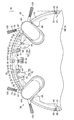
- the vacuum cleaner 11 includes a hollow main body case 12, and the main body case 12 is disposed on a case main body 14 as a main body portion and an outer edge (outer peripheral surface) of the main body case 12 disposed on an outer edge portion of the case main body 14. ) Is movably connected via a pair of link mechanisms 16 and 16 that are paired with a bumper 15 which is a buffer member constituting a part of the material, and is formed into a flat cylindrical shape (disk shape) or the like as a whole. ing.
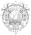
- the electric blower 21 is accommodated in the case main body 14, and a dust collecting portion 22 communicating with the suction side of the electric blower 21 is provided at the rear portion, for example, so as to be detachable. .
- the main body case 12 includes, for example, a plurality of (a pair of) driving wheels 23 as a pair of driving portions, a plurality of driven wheels 24, a plurality of distance detecting means (distance detecting portions), and a pair of distance measuring sensors 25.
- Side brushes 26 and 26, which are swirl cleaning units as a cleaning unit, a control unit (control means) 27 configured by a circuit board, a communication unit 28 for wireless communication with an external device, and a power supply unit And a secondary battery 29 which is a battery to be operated.
- the direction along the traveling direction of the vacuum cleaner 11 (main body case 12) is the front-rear direction (arrow FR, RR direction shown in FIG.
- the case body 14 is roughly an upper surface 31 that is a decorative plate formed of, for example, a hard synthetic resin, a lower surface 32 that is a decorative plate, and a rear outer periphery that is a decorative plate as a main body outer surface (case main body outer surface)
- the outer surface is covered by the surface 33, and a structure portion 34 composed of a plurality of case bodies is formed inside the upper surface 31, the lower surface 32, and the rear outer peripheral surface 33.
- a portion extending from both sides to the front side of the case main body 14 is an arcuate opening 35 into which the bumper 15 is fitted.
- the upper surface 31 constitutes the upper surface of the main body case 12, is a circular flat plate in plan view, and extends in the horizontal direction.
- a dust collector lid portion 37 that is opened and closed when the dust collector 22 is attached and detached is provided at the rear portion of the upper surface 31.
- the lower surface 32 constitutes the lower surface of the main body case 12, is a circular flat plate in plan view, and extends in the horizontal direction.
- the lower surface 32 is provided with a plurality of exhaust ports 41 for exhausting the exhaust from the electric blower 21 and a suction port 42 that is a dust collection port communicating with the dust collection unit 22.
- Driving wheels 23 and 23 are arranged at positions closer to the front of both sides.
- a rotary brush 43 as a rotary cleaning body is rotatably attached to the suction port.
- the rotary brush 43 is provided with a cleaning member 43a such as a bristle brush or a blade on the outer peripheral surface, and is rotated by a brush motor 44 (FIG. 8) as a rotation drive means (rotation drive unit). By repeatedly contacting the surface to be cleaned, dust on the surface to be cleaned is picked up.
- the rear outer peripheral surface 33 constitutes a portion extending from both sides to the rear side of the case main body 14, that is, an outer peripheral surface (outer surface) for substantially the latter half of the main body case 12, and has an axial direction along the vertical vertical direction and has a predetermined direction.
- outer peripheral surface outer surface
- the structural portion 34 is basically a portion that is accommodated inside the main body case 12 without being exposed to the outside.
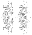
- cylindrical (boss-shaped) shaft support portions 51 and 51 serving as main body side shaft support portions forming a part of the link mechanisms 16 and 16 are positioned between the shaft support portions 51 and 51.
- the urging receiving portion 52 is formed.
- the structure portion 34 is formed with guide portions 53 for guiding the side brushes 26 along the radial direction of the main body case 12 (case main body 14).
- the shaft support portions 51 and 51 are arranged at positions substantially symmetrical with respect to the center line L in the width direction of the structure portion 34 (main body case 12 (case main body 14)), and are arranged on the upper surface 31 of the structure portion 34. It protrudes vertically upward from the upper part facing the lower part.
- the bias receiving part 52 normally biases the bumper 15 by biasing the bumper 15 forward in the position between the link mechanisms 16 and 16 with respect to the case body 14 (a direction away from the case body 14).
- This is the part that receives and holds the rear end of the coil spring 55 as the bumper urging means (bumper urging body) for returning to the position, and is the center in the width direction of the structural part 34 (main body case 12 (case main body 14)).
- the position overlaps with the line L, that is, the central portion in the width direction of the structure portion 34 (main body case 12 (case main body 14)).
- Each guide portion 53 guides the side brushes 26 and 26 so that they can reciprocate in the direction in which the side brushes 26 and 26 protrude from the main body case 12 and the opposite direction, and the side brush in a state in which it protrudes to the main body case 12 to the maximum.
- 26, 26 stoppers, for example, both sides in the width direction of the structural portion 34 (main body case 12 (case main body 14)), in the present embodiment, both oblique sides forward of the center portion in the front-rear direction of the main body case 12 It is formed at a position (45 ° direction on the front left and right of the main body case 12).
- the direction in which the side brush 26 protrudes from the outline of the main body case 12 is referred to as a protruding direction
- the opposite direction is referred to as a retracting direction.
- the bumper 15 elastically relieves an impact at the time of contact (collision) with an obstacle W and has rigidity, for example.
- a bumper body 61 that is formed of a synthetic resin (rigid body) and is curved into a cylindrical surface that forms a portion extending from both sides to the front side of the main body case 12, that is, an outer peripheral surface (outer) of a substantially front half of the main body case 12, and the bumper A plate-like extension 62 extending rearward from the upper end of the main body 61, a bumper-side pivot 63, 63 protruding from the bumper main body 61 and forming a part of the link mechanism 16, 16, and A bumper side urging receiving portion 64 provided on the bumper main body 61 and a side lever 65 provided on the bumper main body 61 are provided between the bumper side pivot support portions 63, 63.
- the bumper 15 is fitted in the opening 35 of the case body 14 and can reciprocate along the radial direction of the case body 14.
- the bumper main body 61 has an axial direction along the vertical vertical direction and has a semicircular arc shape along an arc having the same diameter as the rear outer peripheral surface 33, and the obstacle W or the like is not in contact with the bumper 15 (
- a substantially cylindrical surface (approximately one circle in plan view) is formed together with the rear outer peripheral surface 33 at a normal position where no load is applied. Therefore, the outer peripheral surface of the main body case 12 is configured by the rear outer peripheral surface 33 and the bumper main body 61.
- the bumper body 61 is radially separated from the outer edge portion extending from both sides to the front side of the case body 14 via a predetermined gap, and this gap is the maximum stroke that the bumper 15 can reciprocate. It has become.
- the bumper main body 61 includes brush fitting portions 68 and 68 as cleaning portion fitting portions into which the side brushes 26 and 26 are fitted at positions corresponding to the respective guide portions 53 of the structure portion 34 in the radial direction.
- the bumper main body 61 is provided with protruding portions 70 and 70 as pressing portions on the inner surface facing the case main body 14.
- Each brush fitting portion 68 is formed to be recessed toward the inner peripheral side with respect to the envelope surface, which is a virtual arc surface including the outer peripheral surface forming the outer periphery of the bumper main body 61 (bumper 15).
- Each abutting portion 69 interlocks each side brush 26 and the bumper 15 by abutting each side brush 26 in a state where each side brush 26 has moved a predetermined amount or more in the retracting direction with respect to the main body case 12. It is intended to reciprocate.
- Each protrusion 70 has an inclined flat contact surface 73, and this contact surface 73 is an obstacle detection means (obstacle detection unit) arranged on the case body 14 (structure part 34).
- the obstacle sensor 74 and the bumper 15 are always in contact with each other at the normal position, and each obstacle sensor 74 is operated. Further, each protrusion 70 is disposed in the vicinity of each brush fitting portion 68 at a position on the center line L side with respect to each brush fitting portion 68.
- Each abutment surface 73 protrudes from the inner surface of the bumper body 61 so that the protrusion amount toward the central axis side (rear side) of the bumper body 61 increases as the distance from the center line L increases. That is, the surface direction of each contact surface 73 has a vector component along the front-rear direction and a vector component along the left-right direction. In other words, each contact surface 73 is inclined along the direction intersecting with the front-rear direction and the left-right direction. For this reason, the contact surfaces 73, 73 are inclined in a letter C shape when viewed from above. In addition, each contact surface 73 is disposed with its surface facing the center line L side.
- the obstacle sensors 74 and 74 are arranged so that the protrusions 70 (abutment) are caused by the movement of the bumper 15 and the side brushes 26 and 26 in the retracting direction due to contact with the obstacle W. This movement is detected by contacting the surface 73) or the inner surface of the bumper body 61, and the obstacle W is detected by detecting this movement.
- These obstacle sensors 74 and 74 are disposed substantially symmetrically in the vicinity of the center line L on both sides of the center line L, for example, at the lower part of the structure portion 34, and below the case body 14. It faces the lower surface 32 (FIG. 9) and faces the inner surface of the bumper 15.
- Each obstacle sensor 74 includes a contactor 77 that can be rotated by contacting the bumper 15 side, and a sensor unit 78 that is a detection means body (detection unit body) that detects the rotation of each contactor 77. And contact springs 79 as contact urging means (contact urging bodies) for urging each contact 77 in a direction to rotate toward the bumper 15.
- Each contact 77 is integrally provided with a contact main body 81 formed in a substantially fan shape and a contact portion 82 formed in a substantially fan shape coaxial with the contact main body 81.
- Each contact 77 is pivotally supported at a position near the outer edge of the case main body 14 at the fan-shaped center position of the contact main body 81 and the contact portion 82, and the center line L side rotates along the front-rear direction. It is possible.
- the contact main body 81 is a portion located on the inner side (on the anti-bumper 15 (anti-bumper main body 61) side) than the outer edge of the case main body.
- the outer peripheral surface of the contact body 81 is an arc-shaped sensing surface 84 with the surface facing the center line L side.
- the sensing surface 84 is located along the front-rear direction, and a notch 85 is formed at the position of the rear end.
- the sensing surface 84 is preferably painted black, for example, so as not to reflect light.
- the contact portion 82 has a fan shape with a smaller diameter than the contact main body 81, protrudes to the front side of the contact main body 81, and outward (bumper 15 (bumper main body 61) side) from the outer edge portion of the case main body 14.
- the bumper 15 (bumper body 61) faces the bumper 15 so as to protrude.
- an action surface 87 is formed that always contacts the contact surface 73 of the bumper 15 at the normal position of the bumper 15.
- the action surface 87 is a portion that forms the front edge of the contact portion 82, and extends forward and toward the center line L along the tangential direction of the rotation (rotation shaft) of the contact 77.
- each working surface 87 has a vector component along the front-rear direction and a vector component along the left-right direction.
- each working surface 87 is inclined along the direction intersecting with the front-rear direction and the left-right direction.
- each working surface 87 is arranged with its surface facing outward in the width direction opposite to the center line L. That is, each action surface 87 is located on the side opposite to the sensing surface 84 in each contactor 77.
- Each sensor unit 78 is, for example, a non-contact type photo interrupter, and the light emitting unit 78a and the light receiving unit 78b face each other across the sensing surface 84 of the contact body 81 of each contact 77, and the case body 14 Is arranged. Between the light emitting unit 78a and the light receiving unit 78b, the notch 85 is positioned in a state where the bumper 15 is in the normal position, and the sensing surface 84 is moved to the light emitting unit 78a and the light receiving unit 78b by the rotation of the contact 77. It is designed to be interposed between and.
- each contact spring 79 is held by each contact 77 (contact body 81), and a spring receiving portion 89 as a biasing means receiving portion (biasing body receiving portion) provided in the case body 14 is provided. The other end is held.
- the spring receiving portion 89 is a pivot that regulates a pivot range of the contact 77 on the bumper 15 side forward (advancing direction) by contacting the contact main body 81 with the bumper 15 being in a normal position. It has the function of a regulation part.
- the extending portion 62 is formed in a flat plate shape, and is inserted into the opening 35 and is in close contact with the lower portion of the upper surface 31, thereby closing the upper surface of the gap between the bumper body 61 and the outer edge portion of the case body 14. It is. In other words, the extended portion 62 comes into sliding contact along the lower portion of the upper surface 31 as the bumper 15 reciprocates.
- the bumper-side shaft support parts 63, 63 are arranged so as to be separated from each other at positions substantially symmetrical with respect to the center line L in the width direction of the bumper 15 (main body case 12), and vertically upward from the lower part of the bumper main body 61. It protrudes and the upper part is covered with the extending part 62. And these bumper side axial support parts 63 and 63 and the axial support parts 51 and 51 of the structure part 34 are mutually connected.
- the bumper-side urging receiving portion 64 is a portion that receives and holds the front end portion of the coil spring 55, and overlaps the center line L in the width direction of the bumper main body 61 (main body case 12 (bumper 15)), that is, the bumper main body. 61 (main body case 12 (bumper 15)) is located at the center in the width direction. Therefore, the coil spring 55 is held linearly along the front-rear direction with the center line L as the central axis in a state where the bumper 15 is in the normal position.
- Each side lever 65 supports the bumper 15 against the contact (collision) of the obstacle W from the side. As shown in FIGS. 1 to 3 and FIG. 6, both end portions ( They are arranged on the inner surfaces of the two side portions facing the case body 14.
- These side levers 65 include a lever body 91 pivotally supported on the bumper body 61, and a coil spring 92 as lever urging means (lever urging body) for urging the lever body 91 in the protruding direction. Each is equipped.
- the front side of the lever main body 91 is pivotally supported by the bumper main body 61, and can be rotated along the left-right direction.
- the end of the lever main body 91 is formed in a semi-cylindrical shape so as to be fitted into the receiving portions 93 that are recessed in a circular arc shape on both sides of the case main body 14.
- the position of the bumper 15 is regulated in the front-rear direction with respect to the case body 14.
- the lever main body 91 is restricted from rotating in a direction in which the lever main body 91 protrudes from the bumper main body 61 by contacting a stopper portion 94 provided on the bumper main body 61 in a state where the bumper 15 is in the normal position.
- Each link mechanism 16 includes the shaft support 51, the bumper side shaft support 63, and a connecting body 95 that connects the shaft support 51 and the bumper side shaft support 63, and the bumper 15 is connected to the case body 14. Are relatively movable in the horizontal direction.
- the front end portion of the connecting body 95 is pivotally supported by the bumper side pivot support portion 63 so as to be rotatable in the circumferential direction, and the pivot support portion 51 is inserted through the rear end side so as to be rotatable and slidable in the circumferential direction.
- a long hole 96 is formed. Then, each connecting body 95 rotates with respect to the bumper-side shaft support portion 63 (bumper 15), and the shaft support portion 51 slides along the long hole 96 and rotates within the long hole 96.
- the bumper 15 is movable with respect to the case body 14 along the horizontal direction. That is, the case main body 14, the bumper 15, and the coupling bodies 95 and 95 constitute a link device.
- the link mechanism 16, the coil spring 55, and the side levers 65 are centered so that the center lines L of the bumper 15 and the case main body 14 substantially coincide with each other, and the bumper 15 is maintained in the normal position. It is always energized.
- the electric blower 21 is accommodated in the main body case 12 at a position between the drive wheels 23 and 23, for example.
- the suction side of the electric blower 21 is airtightly connected to the dust collector 22.
- the dust collection unit 22 accumulates the dust sucked from the suction port 42 by driving the electric blower 21, and is a dust collection box that can be attached to and detached from the main body case 12 in this embodiment.
- the drive wheels 23 and 23 enable the body case 12 to travel on the surface to be cleaned (autonomous traveling), that is, for traveling, and are formed in a disk shape having a rotation axis along the horizontal direction (width direction). In the position near the center in the front-rear direction at the lower part of the main body case 12, they are spaced apart from each other in the width direction. And these drive wheels 23 and 23 are rotationally driven via the motors 98 and 98 (FIG. 8) as a drive means (drive part).
- motors 98 and 98 are connected to these drive wheels 23 and 23 via gear boxes as drive transmission means (drive transmission unit) (not shown), respectively, and can drive the drive wheels 23 and 23 independently. It has become.
- the motors 98 and 98 are integrated with the drive wheels 23 and 23 and the gear boxes in a direction protruding downward from the lower surface 32 of the main body case 12 by suspension means (suspension part ((suspension)) not shown). By this urging, the grip force of the drive wheels 23, 23 against the surface to be cleaned is ensured.
- the driven wheel 24 (FIG. 9) is disposed on the lower surface 32 of the main body case 12 so as to be freely rotatable at a position where the weight of the vacuum cleaner 11 can be supported in a well-balanced manner together with the drive wheels 23 and 23.
- the driven wheel 24 at the substantially central portion in the width direction of the lower surface 32 of the main body case 12 and at the front portion is a revolving wheel 99 attached to the lower surface 32 so as to be rotatable in parallel to the surface to be cleaned. It has become.
- the distance measuring sensor 25 is a non-contact type sensor such as an ultrasonic sensor or an infrared sensor, for example, and is disposed on the rear outer peripheral surface 33 and the bumper 15 (bumper main body 61) of the case main body 14 of the main body case 12, for example.
- the presence / absence of obstacles (walls) W etc. outside the case 12 and the distance between them and the main body case 12 can be detected.
- the side brushes 26 and 26 have dust that is located outside the outer side (outer peripheral surface) of the main body case 12 such as the sides of the suction port 42, particularly near the wall, or in front of the drive wheels 23 and 23, where the suction port 42 does not reach.
- the brush fitting portions 68 and 68 of the bumper 15 are scraped and cleaned, that is, both sides in the width direction of the main body case 12, in this embodiment, both sides obliquely ahead of the center portion in the front-rear direction of the main body case 12 It is arranged at a position (45 ° direction on the front left and right of the main body case 12).
- the side brushes 26, 26 protrude outward from the outline of the main body case 12 (bumper 15) at the normal position where no load is applied due to contact with the obstacle W or the like, and the base end side protrudes from the main body case 12 (bumper 15). It is located inward from the outline of 15). And these side brushes 26 and 26 are the brush main body 101 as a cleaning part main body which can advance radially along the radial direction of this main body case 12 with respect to the outline of the main body case 12, and this brush main body 101 is a main body case.
- the brush energizing spring 102 as a cleaning unit energizing means (cleaning unit energizing body) energizing in a direction protruding from the outer shell (outer peripheral surface) of 12 and the lower portion of the brush body 101 facing the surface to be cleaned can be rotated.
- a cleaning body 103 such as a bristle brush disposed on the rotating body 104 and a turning motor 104 as a turning drive means (turning drive unit) for rotating the cleaning body 103 are provided.
- the brush body 101 is formed such that the tip side has a shape along an arc, for example, an elliptical shape in this embodiment.
- the brush body 101 (side brush 26) moves in the retracting direction toward the body case 12 against the urging of the brush urging spring 102 within a predetermined movement range by contact with an obstacle W or the like. It has become.
- the movement range of the brush body 101 (side brush 26) includes a bumper from a position protruding outward with respect to the outer peripheral surface of the bumper main body 61 of the bumper 15, which is the outer shell (outer peripheral surface) of the main body case 12.
- a second movement range in which reciprocation is possible integrally with the bumper 15 while being substantially flush with each other is set. That is, in the brush body 101, a brush contact portion 106, which is an arc-shaped cleaning portion contact portion that can contact the contact portions 69 and 69 of the bumper 15, can be formed. In the movement range, the brush contact portion 106 is separated from the contact portions 69, 69, and the brush body 101 (side brush 26) has moved to the boundary position between the first movement range and the second movement range.
- the brush contact portion 106 contacts the contact portions 69 and 69 so as to reciprocate integrally with the bumper 15.
- the first movement range is set wider than the second movement range, and the first movement range is, for example, 10 mm stroke, and the second movement range is 5 mm stroke.
- the brush urging spring 102 is, for example, a coil spring, and one end side is held by the turning motor 104 and the other end side is a cleaning unit urging means receiving portion (cleaning portion urging body receiving portion) provided in the case main body 14.
- the brush body 101 is held by the spring receiving portion 108 and urges the brush body 101 linearly along the radial direction of the body case 12.
- the turning motor 104 is integrally attached to the base end side of the brush body 101, and is configured to rotate, that is, turn, the cleaning body 103 parallel to the surface to be cleaned.
- the turning motors 104 and 104 turn the cleaning bodies 103 and 103 in opposite directions so as to scrape dust on both sides of the main body case 12 to the center side in the width direction of the main body case 12. That is, the turning motor 104 of the side brush 26 located on the left side turns the cleaning body 103 clockwise (clockwise), and the turning motor 104 of the side brush 26 located on the right side turns the cleaning body 103 counterclockwise ( It is designed to turn counterclockwise.
- the control unit 27 includes, for example, a timer (e.g., a timer), a storage unit (e.g., a memory) such as a memory, and a control unit body such as a microcomputer, the electric blower 21, the distance measuring sensor 25, the communication unit 28, electrically connected to the brush motor 44, the obstacle sensors 74 and 74, the motors 98 and 98, the turning motors 104 and 104, etc., and based on the detection results of the distance measuring sensor 25 and the obstacle sensors 74 and 74
- the electric fan 21 and the brush motor 44 are controlled while controlling the driving of the driving wheels 23 and 23 via the motors 98 and 98 so that the main body case 12 (the vacuum cleaner 11) autonomously travels so as to avoid the obstacle W.
- the electric vacuum cleaner 11 can be cleaned by controlling the driving of the swing motors 104, 104 and the like.
- the communication unit 28 is disposed at the central portion in the width direction at the extending portion 62 of the bumper 15 so as to reciprocate integrally with the bumper 15. Therefore, an arc-shaped cutout recess 109 for avoiding interference with the communication unit 28 is cut out at the center in the width direction of the front end portion of the upper surface 31 of the case body 14.
- the secondary battery 29 (FIG. 8) supplies power to the control unit 27, the electric blower 21, the distance measuring sensor 25, the communication unit 28, the brush motor 44, the motors 98 and 98, the turning motors 104 and 104, and the like.
- the secondary battery 29 is disposed at a position between the drive wheels 23 and 23, for example, behind the turning wheel.
- the secondary battery 29 is electrically connected to a charging terminal located on the lower surface 32 of the main body case 12.For example, the secondary battery 29 is connected to a predetermined charging stand (not shown) installed at a predetermined position in a room (room). Thus, charging is possible by connecting the charging terminal.
- the driving wheels 23 and 23 When the vacuum cleaner 11 is placed on the surface to be cleaned, the driving wheels 23 and 23 come into contact with the surface to be cleaned, and the driving wheels 23 and 23 are energized by the suspension means (suspension part) by the weight of the vacuum cleaner 11.
- the driven wheel 24 (swivel wheel 99) sinks into the body case 12 together with the gearboxes against the surface to be cleaned, and there is a predetermined gap between the suction port 42 and the surface to be cleaned. It is formed.
- this vacuum cleaner 11 will drive the electric blower 21, for example, will start cleaning, for example from a charging stand, when the predetermined time etc. which were preset by the control part 27 will be reached.
- the cleaning start position can be set at an arbitrary place such as the travel start position of the electric vacuum cleaner 11 or the entrance / exit of the room.
- the control unit 27 drives the electric blower 21, and the motors 98 and 98 are connected to the distance W and the obstacle W via the distance measuring sensor 25 and each obstacle sensor 74.
- the position of the vacuum cleaner 11 and the running state are monitored by detecting the contact of the sensor, and on the surface to be cleaned while avoiding the obstacle W in response to the detection of these sensors 25 and 74, if necessary.
- the side brushes 26 and 26 and the rotating brush 43 are operated to clean the surface to be cleaned.
- the notch portion 85 is positioned between the light emitting portion 78a and the light receiving portion 78b, respectively, and the light emission from the light emitting portion 78a is performed.
- Light can be received by the light receiving unit 78b.
- each contact 77 rotates backward against the bias of each contact spring 79. That is, the backward movement of the bumper 15 is converted into the backward rotation operation of each contact 77.
- the sensing surface 84 moves between the light emitting portion 78a and the light receiving portion 78b of each sensor portion 78, and the sensing surface 84 emits light. Light reception from the light receiving unit 78b from the light emitting unit 78a is blocked. Therefore, each sensor unit 78 detects the rotation of the contact 77, that is, the backward movement of the bumper 15, by detecting that light is no longer received by the light receiving unit 78b by the output from the light receiving unit 78b.
- the contact of the obstacle W with the bumper 15, in other words, the presence of the obstacle W is indirectly detected.
- the connecting body 95 of the link mechanism 16 has the front part pivotally supported by the bumper side pivotal support part 63 on the other side with respect to the rear part where the pivotal support part 51 of the case body 14 is inserted into the long hole 96 ( Left side) so that the lever main body 91 of the side lever 65 located on one side (right side) on the obstacle W side is coil spring while being rotated in an inclined manner while maintaining a parallel state to each other. Rotates outward against 92 bias.
- the protrusion 70 moves to the other side integrally with the movement of the bumper 15 to the other side, the contact surface 73 of the protrusion 70 and the action surface 87 of the contact 77 move in the front-rear direction and the left-right direction.
- the contact surface 73 pushes the action surface 87 of the contact 77 to the side by being inclined with respect to each other. This pressure is converted into a backward pressing force by the inclination of the working surface 87, and the contact 77 is pushed backward, and the contact 77 moves backward against the bias of the contact spring 79.
- the contact surface 73 does not press the action surface 87 of the contact 77, and the contact 77 rotates. do not do.
- the obstacle sensor 74 located on the obstacle W side converts the lateral movement of the bumper 15 into a rotational movement of the contact 77 backward.
- the sensor part 78 of the obstacle sensor 74 (on the right side) located on the obstacle W side the light receiving part for emitting light from the light emitting part 78a by the sensing surface 84 moved between the light emitting part 78a and the light receiving part 78b. Since the light reception by 78b is cut off, the contact 77 is rotated, that is, the bumper 15 side is detected by detecting from the light reception unit 78b that light is no longer received by the light reception unit 78b as described above. , And the contact of the obstacle W with the bumper 15 is indirectly detected.
- the bumper 15 is inclined backward with respect to the case body 14.
- the action surface 87 of the contact 77 of the obstacle sensor 74 located on the obstacle W side is pushed by the abutment surface 73 of the protrusion 70 of the bumper 15 and is on the opposite side of the obstacle W.
- the acting surface 87 of the contact 77 of the obstacle sensor 74 positioned is separated from the contact surface 73 of the protrusion 70 and is pushed by the inner surface of the bumper 15, and similarly, the rotation of the contact 77, that is, the bumper 15
- the movement is detected, and the contact of the obstacle W with the bumper 15 is indirectly detected.
- the obstacle sensor 74 is configured such that the direction of the obstacle W that contacts the bumper 15 changes from the front to the side. The more the movement, the faster the detection by the obstacle sensor 74 located on the obstacle W side is faster than the detection by the obstacle sensor 74 on the opposite side, and when the obstacle W comes in contact with the side of the bumper 15, the obstacle W It is detected only by the obstacle sensor 74 located on the side, and is not detected by the obstacle sensor 74 on the opposite side. Therefore, the obstacle sensors 74 and 74 can detect the direction of the obstacle W based on the presence / absence of detection and the detection timing (detection time difference).
- the bumper 15 in contact with the obstacle W is kept in contact with the obstacle W by the urging of the coil spring 55, and the vacuum cleaner 11 (main body case 12) moves to a position where it does not come into contact with the obstacle W. Sometimes it returns to its original normal position.
- each side brush 26 protruding outward from the outer surface of the bumper 15 (main body case 12), that is, the outer surface of the bumper main body 61 of the bumper 15, as shown in FIG.
- the brush 26 moves into the brush fitting portion 68 along the guide portion 53 toward the center side (retracting direction) of the main body case 12 against the bias of the brush biasing spring 102.
- the side brushes 26 are substantially flush with each other in the first movement range, that is, from the outside of the outer shell of the bumper 15 (main body case 12). Up to a certain position, it reciprocates independently (without interlocking) with respect to the bumper 15 (FIG. 5 (a)).
- Each side brush 26 is formed so that the tip side is formed along a circular arc, so that, for example, when the electric vacuum cleaner 11 (main body case 12) is turned, the tangential direction of the turn with respect to the obstacle W (the main body case 12).
- the external force applied by the contact is converted into the retracting direction and can be moved in the retracting direction toward the main body case 12 even when the contact is made along the tangential direction.
- each side brush 26 is within the second movement range, that is, between the position where the tip side is substantially flush with the outer envelope surface of the bumper 15 (main body case 12) and the inner position thereof.
- each side brush 26 acts as a part of the bumper 15 within the second movement range that is a position moved by a predetermined amount or more in the retreat direction, and each side brush 26 is obstructed within this second movement range.
- the obstacle sensor 74 detects the rotation of the contact 77 and indirectly detects the obstacle W in the same manner as the operation of the bumper 15 shown in FIGS.
- each side brush 26 which contacted the obstacle W maintains the state which contacts the obstacle W by the urging
- the vacuum cleaner 11 of the present embodiment can detect the obstacle W in contact with the front half of the outer case of the main body case 12 by each obstacle sensor 74.
- the vacuum cleaner 11 When the obstacle W is detected, the vacuum cleaner 11 operates to avoid the obstacle W. For example, in a direction away from the obstacle W, that is, to the rear, the side brush 26 and the bumper 15 do not collide with each other (the obstacle sensor 74 does not detect the obstacle W), or turn at that position and move forward. The direction of the direction is changed to a direction not facing the obstacle W.
- the vacuum cleaner 11 sucks dust on the surface to be cleaned or dust collected by the side brushes 26 and 26 together with the air through the suction port 42 to which the negative pressure generated by driving the electric blower 21 is applied. . Further, the rotating brush 43 scoops up dust on the surface to be cleaned from the suction port.
- Dust sucked from the suction port 42 or dust picked up by the suction port 42 is introduced into the dust collecting unit 22 and collected, and the air from which the dust has been separated is sucked into the electric blower 21, and this electric motor After cooling the blower 21, exhaust air is exhausted from the exhaust port 41 to the outside of the main body case 12.
- control unit 27 causes the vacuum cleaner 11 to autonomously travel to the position of the charging base, stops the electric blower 21 and the like, and sets the charging terminal on the charging base (physical And the motors 98 and 98 are stopped, the operation is terminated, and the secondary battery 29 is charged.
- the bumper 15 is connected to the case body 14 by the link mechanisms 16 and 16 so as to be relatively movable in the horizontal direction, and the bumper 15 is connected between the link mechanisms 16 and 16 in the case.
- the bumper 15 Energizing in a direction away from the main body 14, the bumper 15 contacts the obstacle W, and the rear direction opposite to the energizing direction of the coil spring 55 intersects with this direction. Since the obstacle W is detected by detecting the movement in at least one of the directions by the obstacle sensors 74 and 74, a simple configuration without complicating the configuration by providing a large number of sensors or switches.
- the obstacle W in contact with the bumper 15 can be detected in a wide range extending from both sides to the front with respect to the bumper 15, that is, in a substantially front half of the main body case 12.
- each obstacle sensor 74 can detect the obstacle W by converting the movement of the bumper 15 into the rotation of the contact 77. Therefore, for example, the obstacle sensor 74 can be saved as compared with a configuration that operates along the movement of the bumper 15. Can be configured into a space.
- each obstacle sensor 74 uses the sensing surface 84 of the contactor 77 to detect the rotation of the contactor 77 by the non-contact type sensor unit 78, so that the rotation of the contactor 77 can be performed with a simple configuration. Motion can be detected more easily and reliably.
- the contact 77 is rotated by pushing the acting surface 87 along the tangential direction of the rotation of the contact 77 by the protrusion 70 (contact surface 73) of the bumper 15, the backward movement of the bumper 15 is performed.
- the pressing direction of the action surface 87 due to the movement in the left-right direction can be reliably converted into the pressing direction to the rotation direction of the contact 77, and the contact 77 can be rotated more easily and reliably.
- the obstacle sensors 74 and 74 can be arranged in a space-saving manner with a simple configuration.
- the obstacle sensors 74 and 74 are disposed in the vicinity of the center line L, the obstacle sensors 74 and 74 are hardly affected by the bending of the bumper 15 and the movement of the bumper 15 can be detected reliably and efficiently.
- the obstacle sensors 74 and 74 detect the direction of the obstacle W based on the presence / absence and detection timing of each, the direction of the obstacle W relative to the main body case 12 can be determined without using an expensive sensor. It can be easily recognized and can travel autonomously while avoiding the obstacle W more reliably.
- the side brushes 26 and 26 can be reciprocated in conjunction with the bumper 15 in a state in which the outline and the front end side of the bumper 15 are moved in the retracting direction to a substantially flush position, the positions of the side brushes 26 and 26 are also determined. It can be used to detect the obstacle W, and the range in which the obstacle W cannot be detected can be reduced (eliminated).
- the obstacle sensor 74 is configured to detect the front-rear direction and the left-right direction.
- the front-rear direction and the left-right direction may be provided separately.
- the side brush 26 moves forward and backward integrally with the bumper 15 in the second movement range, the side brush 26 and the bumper 15 may not be interlocked.
- the side brush 26 may be provided only on either the left or right side of the main body case 12, or the side brush 26 may not be provided.
Abstract
Description
Claims (6)
- 本体部、および、この本体部の外縁部に配置されたバンパを備えた本体ケースと、
この本体ケースを走行可能とする駆動輪と、
前記バンパを前記本体部に対して相対的に水平方向に移動可能に接続するリンク機構と、
前記バンパを前記本体部に対して離間する方向に付勢するバンパ付勢体と、
前記バンパと対向する位置にて前記本体部にそれぞれ配置され、前記バンパの障害物との接触による前記バンパ付勢体の付勢方向に対して反対方向とこの方向に対して交差する方向との少なくともいずれかへの移動を検出することで障害物を検出する対をなす障害物検出部と、
これら障害物検出部による障害物の検出に基づいて前記駆動輪の駆動を制御することで前記本体ケースを自律走行させる制御部と
を具備したことを特徴とした自律走行体。 A main body case, and a main body case provided with a bumper disposed on the outer edge of the main body portion;
A drive wheel that allows the main body case to travel,
A link mechanism for connecting the bumper so as to be movable in a horizontal direction relative to the main body, and
A bumper urging body that urges the bumper in a direction away from the main body portion;
A direction opposite to the urging direction of the bumper urging body due to contact with an obstacle of the bumper, and a direction intersecting with this direction, which are arranged on the main body at positions facing the bumper, respectively. A pair of obstacle detection units that detect obstacles by detecting movement to at least one of the following;
An autonomous traveling body comprising: a control unit that autonomously travels the main body case by controlling driving of the driving wheel based on detection of an obstacle by the obstacle detection unit. - 各障害物検出部は、バンパの移動を回動に変換することにより障害物を検出可能である
ことを特徴とした請求項1記載の自律走行体。 The autonomous traveling body according to claim 1, wherein each obstacle detection unit can detect an obstacle by converting movement of the bumper into rotation. - 各障害物検出部は、
本体部に回動可能に設けられ、バンパに向けて回動する方向に付勢されているとともに、前記本体部に対する前記バンパの移動によりこのバンパによって押されて付勢に抗して回動する接触子と、
この接触子の回動を検出することで前記バンパの障害物との接触を検出する非接触型のセンサ部とを備えている
ことを特徴とした請求項2記載の自律走行体。 Each obstacle detection unit
The main body is rotatably provided and is urged in a direction to rotate toward the bumper, and is pushed by the bumper by the movement of the bumper relative to the main body and rotates against the urging. A contact,
The autonomous traveling body according to claim 2, further comprising a non-contact type sensor unit that detects contact of the bumper with an obstacle by detecting rotation of the contact. - 接触子は、回動の接線方向に沿って設けられた作用面を有し、
バンパは、本体部と対向する位置に、この本体部に対する移動によって前記作用面を押す押圧部を備えている
ことを特徴とした請求項3記載の自律走行体。 The contact has a working surface provided along a tangential direction of rotation,
The autonomous traveling body according to claim 3, wherein the bumper includes a pressing portion that presses the action surface by movement with respect to the main body portion at a position facing the main body portion. - 各障害物検出部は、本体ケースの前後方向に沿う中心線に対して互いに反対側に配置され、各接触子の作用面が前記中心線側に対して反対側に位置し、前記各接触子の前記中心線側が前後方向に沿って回動可能となっている
ことを特徴とした請求項4記載の自律走行体。 Each obstacle detection unit is arranged on the opposite side to the center line along the front-rear direction of the main body case, and the contact surface of each contact is located on the opposite side to the center line side. The autonomous traveling body according to claim 4, wherein the center line side is rotatable along a front-rear direction. - 対をなす障害物検出部は、それぞれの検出の有無および検出タイミングに基づいて障害物の方向を検出可能である
ことを特徴とした請求項1ないし5いずれか一記載の自律走行体。 The autonomous traveling body according to any one of claims 1 to 5, wherein the pair of obstacle detection units can detect the direction of the obstacle based on the presence / absence of detection and the detection timing.
Priority Applications (5)
| Application Number | Priority Date | Filing Date | Title |
|---|---|---|---|
| US15/304,979 US10201261B2 (en) | 2014-04-22 | 2015-04-22 | Autonomous traveling body |
| CN201580020917.0A CN106233218B (en) | 2014-04-22 | 2015-04-22 | Autonomous traveling body |
| KR1020167009276A KR101902277B1 (en) | 2014-04-22 | 2015-04-22 | Autonomous traveling body |
| EP15783236.1A EP3136196A4 (en) | 2014-04-22 | 2015-04-22 | Autonomous traveling body |
| CA2946142A CA2946142C (en) | 2014-04-22 | 2015-04-22 | Autonomous traveling body |
Applications Claiming Priority (2)
| Application Number | Priority Date | Filing Date | Title |
|---|---|---|---|
| JP2014088362A JP6345973B2 (en) | 2014-04-22 | 2014-04-22 | Autonomous vehicle |
| JP2014-088362 | 2014-04-22 |
Publications (1)
| Publication Number | Publication Date |
|---|---|
| WO2015163374A1 true WO2015163374A1 (en) | 2015-10-29 |
Family
ID=54332537
Family Applications (1)
| Application Number | Title | Priority Date | Filing Date |
|---|---|---|---|
| PCT/JP2015/062265 WO2015163374A1 (en) | 2014-04-22 | 2015-04-22 | Autonomous traveling body |
Country Status (7)
| Country | Link |
|---|---|
| US (1) | US10201261B2 (en) |
| EP (1) | EP3136196A4 (en) |
| JP (1) | JP6345973B2 (en) |
| KR (1) | KR101902277B1 (en) |
| CN (1) | CN106233218B (en) |
| CA (1) | CA2946142C (en) |
| WO (1) | WO2015163374A1 (en) |
Cited By (6)
| Publication number | Priority date | Publication date | Assignee | Title |
|---|---|---|---|---|
| CN107045341A (en) * | 2016-02-05 | 2017-08-15 | 金宝电子工业股份有限公司 | Self-propelled vehicle protection device |
| JP2018153375A (en) * | 2017-03-17 | 2018-10-04 | 日立アプライアンス株式会社 | Electric apparatus, autonomous traveling vacuum cleaner as electric apparatus and system including electric apparatus and base |
| EP3498144A1 (en) * | 2017-12-15 | 2019-06-19 | Seb S.A. | Floor cleaning robot |
| EP3459420A4 (en) * | 2016-05-20 | 2020-03-04 | LG Electronics Inc. -1- | Robot cleaner |
| US10827895B2 (en) | 2016-05-20 | 2020-11-10 | Lg Electronics Inc. | Autonomous cleaner |
| US11846937B2 (en) | 2016-05-20 | 2023-12-19 | Lg Electronics Inc. | Autonomous cleaner |
Families Citing this family (35)
| Publication number | Priority date | Publication date | Assignee | Title |
|---|---|---|---|---|
| EP3166463A1 (en) * | 2014-07-07 | 2017-05-17 | Carl Freudenberg KG | Movable device |
| JP2017136218A (en) * | 2016-02-04 | 2017-08-10 | 日立アプライアンス株式会社 | Autonomous travel type vacuum cleaner |
| JP6685751B2 (en) * | 2016-02-15 | 2020-04-22 | 東芝ライフスタイル株式会社 | Vacuum cleaner |
| US10362916B2 (en) | 2016-05-20 | 2019-07-30 | Lg Electronics Inc. | Autonomous cleaner |
| WO2017200353A1 (en) * | 2016-05-20 | 2017-11-23 | 엘지전자 주식회사 | Robot cleaner |
| WO2017200348A1 (en) | 2016-05-20 | 2017-11-23 | 엘지전자 주식회사 | Robot cleaner |
| WO2017200351A1 (en) | 2016-05-20 | 2017-11-23 | 엘지전자 주식회사 | Robot cleaner |
| WO2017200344A1 (en) | 2016-05-20 | 2017-11-23 | 엘지전자 주식회사 | Robot cleaner |
| WO2017200347A1 (en) | 2016-05-20 | 2017-11-23 | 엘지전자 주식회사 | Robot cleaner |
| US10420448B2 (en) | 2016-05-20 | 2019-09-24 | Lg Electronics Inc. | Autonomous cleaner |
| US10342400B2 (en) | 2016-05-20 | 2019-07-09 | Lg Electronics Inc. | Autonomous cleaner |
| US10524628B2 (en) | 2016-05-20 | 2020-01-07 | Lg Electronics Inc. | Autonomous cleaner |
| CN109874487B (en) | 2016-06-30 | 2022-11-04 | 创科(澳门离岸商业服务)有限公司 | Autonomous mower and navigation system thereof |
| US11172608B2 (en) | 2016-06-30 | 2021-11-16 | Tti (Macao Commercial Offshore) Limited | Autonomous lawn mower and a system for navigating thereof |
| CN206443655U (en) * | 2016-09-13 | 2017-08-29 | 深圳市银星智能科技股份有限公司 | The touching sensing device and robot of a kind of robot |
| CN106313046A (en) * | 2016-09-27 | 2017-01-11 | 成都普诺思博科技有限公司 | Multi-level obstacle avoidance system of mobile robot |
| KR20180106225A (en) | 2017-03-17 | 2018-10-01 | 엘지전자 주식회사 | Robot cleaner |
| KR102021828B1 (en) | 2017-08-07 | 2019-09-17 | 엘지전자 주식회사 | Cleaner |
| KR102014141B1 (en) * | 2017-08-07 | 2019-10-21 | 엘지전자 주식회사 | Robot Cleaner |
| KR102000068B1 (en) | 2017-08-07 | 2019-07-15 | 엘지전자 주식회사 | Cleaner |
| KR102024089B1 (en) | 2017-08-07 | 2019-09-23 | 엘지전자 주식회사 | Robot Cleaner |
| KR102033936B1 (en) | 2017-08-07 | 2019-10-18 | 엘지전자 주식회사 | Robot Cleaner |
| KR102014140B1 (en) | 2017-08-07 | 2019-08-26 | 엘지전자 주식회사 | Robot Cleaner |
| CA3074702C (en) * | 2017-09-07 | 2022-11-22 | Sharkninja Operating Llc | Robotic cleaner |
| KR102045003B1 (en) | 2018-01-25 | 2019-11-14 | 엘지전자 주식회사 | Controlling Method of Robot Cleaner |
| KR20210035280A (en) | 2018-08-01 | 2021-03-31 | 샤크닌자 오퍼레이팅 엘엘씨 | Robot vacuum cleaner |
| JP7156865B2 (en) * | 2018-08-30 | 2022-10-19 | 川崎重工業株式会社 | Shock absorber and robot equipped with same |
| CN109008829A (en) * | 2018-09-17 | 2018-12-18 | 北京石头世纪科技有限公司 | Intelligent cleaning equipment |
| CN109199252B (en) * | 2018-11-16 | 2021-09-14 | 邵勤俏 | Sweeping robot with wide sweeping range |
| TWI698211B (en) * | 2019-01-15 | 2020-07-11 | 燕成祥 | Full-floating contact changing device of cleaning robot |
| JP7369592B2 (en) * | 2019-10-30 | 2023-10-26 | 株式会社マキタ | Detection device and robot dust collector |
| TW202133784A (en) * | 2020-01-20 | 2021-09-16 | 日商松下知識產權經營股份有限公司 | Autonomous mobile cleaner for enhancing safety of autonomous mobile cleaner |
| CN112606018B (en) * | 2020-12-16 | 2022-04-19 | 科沃斯商用机器人有限公司 | Hit board subassembly and from mobile robot |
| CN113576326B (en) * | 2021-07-07 | 2023-01-24 | 北京顺造科技有限公司 | Automatic cleaning equipment |
| EP4343480A1 (en) * | 2022-09-21 | 2024-03-27 | Vorwerk & Co. Interholding GmbH | Automatically moveable soil working device with an obstacle detection device comprising a bumper and at least one impact sensor |
Citations (2)
| Publication number | Priority date | Publication date | Assignee | Title |
|---|---|---|---|---|
| JP2005280423A (en) * | 2004-03-29 | 2005-10-13 | Sanyo Electric Co Ltd | Traveling truck |
| JP2012064240A (en) * | 2001-06-12 | 2012-03-29 | Irobot Corp | Mobile robot cleaner |
Family Cites Families (9)
| Publication number | Priority date | Publication date | Assignee | Title |
|---|---|---|---|---|
| SE518482C2 (en) | 2001-02-28 | 2002-10-15 | Electrolux Ab | Obstacle detection system for a self-cleaning cleaner |
| US8396592B2 (en) | 2001-06-12 | 2013-03-12 | Irobot Corporation | Method and system for multi-mode coverage for an autonomous robot |
| US7429843B2 (en) | 2001-06-12 | 2008-09-30 | Irobot Corporation | Method and system for multi-mode coverage for an autonomous robot |
| AU2004202834B2 (en) | 2003-07-24 | 2006-02-23 | Samsung Gwangju Electronics Co., Ltd. | Robot Cleaner |
| JP2005271152A (en) * | 2004-03-25 | 2005-10-06 | Funai Electric Co Ltd | Self-running vacuum cleaner and self-running robot |
| JP2007330567A (en) | 2006-06-16 | 2007-12-27 | Hitachi Appliances Inc | Self-traveling type vacuum cleaner |
| WO2008007830A1 (en) | 2006-07-14 | 2008-01-17 | Hanulkid Co., Ltd. | Steam robot cleaner |
| KR101311296B1 (en) | 2011-07-06 | 2013-09-25 | 주식회사 유진로봇 | Bumper assembly for moving robot |
| US9615714B2 (en) * | 2012-11-09 | 2017-04-11 | Samsung Electronics Co., Ltd. | Autonomous cleaning device |
-
2014
- 2014-04-22 JP JP2014088362A patent/JP6345973B2/en active Active
-
2015
- 2015-04-22 KR KR1020167009276A patent/KR101902277B1/en active IP Right Grant
- 2015-04-22 EP EP15783236.1A patent/EP3136196A4/en not_active Withdrawn
- 2015-04-22 WO PCT/JP2015/062265 patent/WO2015163374A1/en active Application Filing
- 2015-04-22 US US15/304,979 patent/US10201261B2/en not_active Expired - Fee Related
- 2015-04-22 CN CN201580020917.0A patent/CN106233218B/en active Active
- 2015-04-22 CA CA2946142A patent/CA2946142C/en not_active Expired - Fee Related
Patent Citations (2)
| Publication number | Priority date | Publication date | Assignee | Title |
|---|---|---|---|---|
| JP2012064240A (en) * | 2001-06-12 | 2012-03-29 | Irobot Corp | Mobile robot cleaner |
| JP2005280423A (en) * | 2004-03-29 | 2005-10-13 | Sanyo Electric Co Ltd | Traveling truck |
Non-Patent Citations (1)
| Title |
|---|
| See also references of EP3136196A4 * |
Cited By (15)
| Publication number | Priority date | Publication date | Assignee | Title |
|---|---|---|---|---|
| CN107045341A (en) * | 2016-02-05 | 2017-08-15 | 金宝电子工业股份有限公司 | Self-propelled vehicle protection device |
| CN107045341B (en) * | 2016-02-05 | 2021-08-10 | 金宝电子工业股份有限公司 | Self-propelled vehicle protection device |
| US10939792B2 (en) | 2016-05-20 | 2021-03-09 | Lg Electronics Inc. | Autonomous cleaner |
| EP3459420A4 (en) * | 2016-05-20 | 2020-03-04 | LG Electronics Inc. -1- | Robot cleaner |
| US10827895B2 (en) | 2016-05-20 | 2020-11-10 | Lg Electronics Inc. | Autonomous cleaner |
| US10827896B2 (en) | 2016-05-20 | 2020-11-10 | Lg Electronics Inc. | Autonomous cleaner |
| US10835095B2 (en) | 2016-05-20 | 2020-11-17 | Lg Electronics Inc. | Autonomous cleaner |
| US10856714B2 (en) | 2016-05-20 | 2020-12-08 | Lg Electronics Inc. | Autonomous cleaner |
| EP3861911A3 (en) * | 2016-05-20 | 2021-12-08 | LG Electronics Inc. | Robot cleaner |
| US11547263B2 (en) | 2016-05-20 | 2023-01-10 | Lg Electronics Inc. | Autonomous cleaner |
| US11846937B2 (en) | 2016-05-20 | 2023-12-19 | Lg Electronics Inc. | Autonomous cleaner |
| JP2018153375A (en) * | 2017-03-17 | 2018-10-04 | 日立アプライアンス株式会社 | Electric apparatus, autonomous traveling vacuum cleaner as electric apparatus and system including electric apparatus and base |
| JP7042031B2 (en) | 2017-03-17 | 2022-03-25 | 日立グローバルライフソリューションズ株式会社 | A system having an autonomous driving type vacuum cleaner and an autonomous traveling type vacuum cleaner and a charging stand. |
| FR3075029A1 (en) * | 2017-12-15 | 2019-06-21 | Seb S.A. | SOIL CLEANING ROBOT |
| EP3498144A1 (en) * | 2017-12-15 | 2019-06-19 | Seb S.A. | Floor cleaning robot |
Also Published As
| Publication number | Publication date |
|---|---|
| KR101902277B1 (en) | 2018-09-28 |
| US10201261B2 (en) | 2019-02-12 |
| CA2946142C (en) | 2019-02-19 |
| KR20160054567A (en) | 2016-05-16 |
| JP6345973B2 (en) | 2018-06-20 |
| CN106233218A (en) | 2016-12-14 |
| EP3136196A4 (en) | 2017-12-27 |
| EP3136196A1 (en) | 2017-03-01 |
| US20170181591A1 (en) | 2017-06-29 |
| CN106233218B (en) | 2020-01-21 |
| CA2946142A1 (en) | 2015-10-29 |
| JP2015207206A (en) | 2015-11-19 |
Similar Documents
| Publication | Publication Date | Title |
|---|---|---|
| JP6345973B2 (en) | Autonomous vehicle | |
| JP6472605B2 (en) | Electric vacuum cleaner | |
| EP2721987B1 (en) | Method of controlling automatic cleaner | |
| KR101892652B1 (en) | Electric cleaner | |
| JP2020099802A (en) | Autonomous travel-type cleaner | |
| WO2016031706A1 (en) | Autonomous travel body and vacuum cleaner | |
| KR20210133918A (en) | Robot cleaner | |
| WO2016056226A1 (en) | Autonomous travel-type cleaner | |
| WO2018123321A1 (en) | Autonomous travel-type cleaner | |
| JP2017213009A (en) | Autonomous travel type cleaner | |
| JP6198234B2 (en) | Robot vacuum cleaner with protruding side brush | |
| EP3184016B1 (en) | Vacuum cleaner | |
| JP2020140247A (en) | Autonomous vehicle device |
Legal Events
| Date | Code | Title | Description |
|---|---|---|---|
| 121 | Ep: the epo has been informed by wipo that ep was designated in this application |
Ref document number: 15783236 Country of ref document: EP Kind code of ref document: A1 |
|
| ENP | Entry into the national phase |
Ref document number: 20167009276 Country of ref document: KR Kind code of ref document: A |
|
| ENP | Entry into the national phase |
Ref document number: 2946142 Country of ref document: CA |
|
| WWE | Wipo information: entry into national phase |
Ref document number: 15304979 Country of ref document: US |
|
| REEP | Request for entry into the european phase |
Ref document number: 2015783236 Country of ref document: EP |
|
| WWE | Wipo information: entry into national phase |
Ref document number: 2015783236 Country of ref document: EP |
|
| NENP | Non-entry into the national phase |
Ref country code: DE |