WO2015152582A1 - Method for configuring interference measurement resource in wireless communication system and apparatus for same - Google Patents

Method for configuring interference measurement resource in wireless communication system and apparatus for same Download PDF

Info

Publication number
WO2015152582A1
WO2015152582A1 PCT/KR2015/003099 KR2015003099W WO2015152582A1 WO 2015152582 A1 WO2015152582 A1 WO 2015152582A1 KR 2015003099 W KR2015003099 W KR 2015003099W WO 2015152582 A1 WO2015152582 A1 WO 2015152582A1
Authority
WO
WIPO (PCT)
Prior art keywords
csi
configuration
resource
terminal
channel state
Prior art date
Application number
PCT/KR2015/003099
Other languages
French (fr)
Korean (ko)
Inventor
이승민
서한별
김기준
서인권
김병훈
Original Assignee
엘지전자 주식회사
Priority date (The priority date is an assumption and is not a legal conclusion. Google has not performed a legal analysis and makes no representation as to the accuracy of the date listed.)
Filing date
Publication date
Application filed by 엘지전자 주식회사 filed Critical 엘지전자 주식회사
Priority to EP15774157.0A priority Critical patent/EP3128686A4/en
Priority to JP2016556791A priority patent/JP6309649B2/en
Priority to CN201580018251.5A priority patent/CN106134111B/en
Priority to KR1020167024913A priority patent/KR102287101B1/en
Publication of WO2015152582A1 publication Critical patent/WO2015152582A1/en

Links

Classifications

    • HELECTRICITY
    • H04ELECTRIC COMMUNICATION TECHNIQUE
    • H04LTRANSMISSION OF DIGITAL INFORMATION, e.g. TELEGRAPHIC COMMUNICATION
    • H04L5/00Arrangements affording multiple use of the transmission path
    • H04L5/003Arrangements for allocating sub-channels of the transmission path
    • H04L5/0048Allocation of pilot signals, i.e. of signals known to the receiver
    • HELECTRICITY
    • H04ELECTRIC COMMUNICATION TECHNIQUE
    • H04BTRANSMISSION
    • H04B17/00Monitoring; Testing
    • H04B17/20Monitoring; Testing of receivers
    • H04B17/24Monitoring; Testing of receivers with feedback of measurements to the transmitter
    • HELECTRICITY
    • H04ELECTRIC COMMUNICATION TECHNIQUE
    • H04BTRANSMISSION
    • H04B17/00Monitoring; Testing
    • H04B17/30Monitoring; Testing of propagation channels
    • H04B17/309Measuring or estimating channel quality parameters
    • HELECTRICITY
    • H04ELECTRIC COMMUNICATION TECHNIQUE
    • H04LTRANSMISSION OF DIGITAL INFORMATION, e.g. TELEGRAPHIC COMMUNICATION
    • H04L5/00Arrangements affording multiple use of the transmission path
    • H04L5/003Arrangements for allocating sub-channels of the transmission path
    • H04L5/0032Distributed allocation, i.e. involving a plurality of allocating devices, each making partial allocation
    • H04L5/0035Resource allocation in a cooperative multipoint environment
    • HELECTRICITY
    • H04ELECTRIC COMMUNICATION TECHNIQUE
    • H04LTRANSMISSION OF DIGITAL INFORMATION, e.g. TELEGRAPHIC COMMUNICATION
    • H04L5/00Arrangements affording multiple use of the transmission path
    • H04L5/003Arrangements for allocating sub-channels of the transmission path
    • H04L5/0058Allocation criteria
    • H04L5/0073Allocation arrangements that take into account other cell interferences

Definitions

  • the present invention relates to a wireless communication system, and more particularly, to a method and apparatus for setting interference measurement resources in a wireless communication system.
  • LTE 3rd Generat ion Partnership Project Long Term Evolut ion
  • E-UMTS Evolved Universal Mobility Telecommunication Systems
  • UMTS Universal Mobility Telecommuni ions System
  • LTE Long Term Evolut ion
  • an E-UMTS is located at an end of a user equipment (UE), a base station (eNode B; eNB), and a network (E-UTRAN) and connected to an external network (Access Gateway). AG).
  • the base station may transmit multiple data streams simultaneously for broadcast service, multicast service and / or unicast service.
  • the cell is set to one of the bandwidths of 1.44, 3, 5, 10, 15, 20Mhz, etc. to provide downlink or uplink transmission services to multiple terminals. Different cells can be set to provide different bandwidths.
  • the base station controls data transmission and reception for a plurality of terminals. Downlink (Downl ink;
  • the base station For DL) data, the base station transmits downlink scheduling information to inform the corresponding terminal of time / frequency domain, encoding, data size, HARQ hybr id Automat ic Repeat and reQuest) related information.
  • uplink For uplink (UL) data the base station transmits uplink scheduling information to the terminal to inform the user of the time / frequency domain, encoding, data size, HARQ-related information, and the like.
  • An interface for transmitting user traffic or control traffic may be used between base stations.
  • the core network (CN) may consist of an AG and a network node for user registration of the terminal, and the like.
  • the AG manages the mobility of the UE in units of a TA Tracking Area composed of a plurality of cells.
  • Wireless communication technology has been developed up to LTE based on WCDMA, but the demands and expectations of users and operators continue to be met.
  • new technological advances are required to be competitive in the future. Reduced cost per bit, increased service availability, flexible use of frequency bands, simple structure and open interface, and adequate power consumption of the terminal are required.
  • An object of the present invention is to provide an interference measurement resource setting method and apparatus therefor in a wireless communication system.
  • a method of transmitting a channel state information-reference signal (CSI-RS) by a base station in a wireless communication system which is an aspect of the present invention for solving the above problems, is described in detail.
  • the first terminal is a transmission mode 1 to transmission mode 9 based terminal.
  • the second terminal is a transmission mode 1 to transmission mode 9 based terminal that performs CSI measurement based on the first CSI subframe set and the second CSI subframe set according to the information element. Can be characterized.
  • the zeroTxPowerResourceConfigst parameter and the zeroTxPowerSubfRAMConfig parameter for the first ZP-CSI-RS configuration and the second ZP-CSI-RS configuration may be defined independently of each other.
  • the method may further include reporting channel state information based on the first CSI subframe set and the second CSI subframe set.
  • the first CSI subframe set and the second CSI subframe set may be characterized in that the limited CSI measurement subframe set (Restr icted CSI measurement subfrarae set).
  • a method for a terminal to report channel state information (CSI) in a wireless communication system includes: first channel state information (Channel State Informat); receiving an Informat ion Element for setting the CSI subframe set and the second CSI subframe set; And receiving a CSI-RS configuration including at least one ZP-CSI-RS configuration, wherein the CSI-RS configuration comprises: a first ZP-CSI-RS configuration; And a second ZP-CSI-RS setting applied when the information element is set.
  • the first ZP-CSI-RS configuration is defined for a transmission mode 1 to transmission mode 9 based terminal, and the second ZP-CSI-RS configuration is determined according to the information element. It may be characterized in that it is defined for transmission mode 1 to transmission mode 9 based UE performing CSI measurement based on the first CSI subframe set and the second CSI subframe set.
  • the base station for transmitting the signal, CSI-RS) setting includes: a radio frequency unit (Radio frequency unit); And a processor, wherein the processor comprises: an information element for setting a sum of a first channel state information (CSI) subframe set and a second channel state information (CSI) subframe sum; And transmit the CSI-RS settings including at least one ZP-CSI-RS configuration (Zero Power CSI-RS conf igurat ion), wherein the CSI-RS configuration includes: And a first ZP-CSI-RS configuration for the first terminal that is not set and the second terminal for which the information element is set, and a second ZP-CSI-RS configuration for the second terminal only.
  • ZP-CSI-RS configuration includes: And a first ZP-CSI-RS configuration for the first terminal that is not set and the second terminal for which the information element is set, and a second ZP-CSI-RS configuration for the second terminal only.
  • a terminal for reporting channel state information (CSI) in a wireless communication system includes: a radio frequency unit (Radio frequency unit); And a processor, wherein the processor comprises: an information element for setting a first channel state information (CSI) subframe set and a second channel state information (CSI) subframe set And receive a CSI-RS configuration comprising at least one ZP-CSI-RS configuration (Zero Power CSI-RS conf igurat ion), wherein the CSI-RS configuration comprises: a first ZP-CSI-RS configuration; And a second ZP-CSI-RS configuration, which is applied when the RS configuration and store information element is configured.
  • CSI channel state information
  • CSI channel state information
  • the CSI-RS configuration comprises: a first ZP-CSI-RS configuration; And a second ZP-CSI-RS configuration, which is applied when the RS configuration and store information element is configured.
  • interference measurement resource setting can be efficiently performed.
  • 1 illustrates an E-UMTS network structure as an example of a wireless communication system.
  • 2 illustrates a control plane and a user plane structure of a radio interface protocol between a terminal and an E-UTRAN based on the 3GPP radio access network standard.
  • 3 shows physical channels used in a 3GPP LTE system and a general signal transmission method using the same.
  • FIG. 4 shows a structure of a radio frame used in an LTE system.
  • 5 shows a resource grid for a downlink slot.
  • FIG. 6 illustrates a structure of a downlink subframe.
  • FIG. 7 shows a structure of an uplink subframe used in LTE.
  • FIG. 9 illustrates a case in which part of an existing uplink resource is changed and used for downlink communication purpose in a TDD system environment.
  • FIG. 10 shows that when each cell dynamically changes the use of an existing radio resource according to its system load state, the interference characteristics received from the outside are determined for each subframe (or subframe set) in the TDD system environment. Another case is shown.
  • Figure 11 illustrates a base station and user equipment that can be applied to an embodiment of the present invention.
  • CDMA code division multiple access
  • FDMA frequency division multiple access
  • TDMA time division multiple access
  • OFDMA orthogonal frequency division multiple access
  • SC-FDMA single carrier frequency division multiple access
  • CDMA may be implemented by a radio technology such as UTRACUniversal Terrestrial Radio Access) or CDMA2000.
  • TDMA can be implemented with wireless technologies such as Global System for Mobility Communications (GSM) / General Packet Radio Service (GPRS) / Enhanced Data Rates for GSM Evolution (EDGE).
  • GSM Global System for Mobility Communications
  • GPRS General Packet Radio Service
  • EDGE Enhanced Data Rates for GSM Evolution
  • 0FDMA may be implemented by a wireless technology such as IEEE 802.11 (Wi-Fi), IEEE 802.16 (WiMAX), IEEE 802-20, Evolved UTRA (E-UTRA), or the like.
  • UTRA is part of the UMTSCUniversal Mobile Telecom unications System.
  • 3rd Generation Partnership Project (3GPP) long term evolution (LTE) uses E—UTRA
  • E-UMTS Evolved UMTS
  • 0FDMA is adopted in the downlink and SC-FDMA is adopted in the uplink.
  • LTE-A Advanced
  • LTE-A Advanced
  • the present invention focuses on 3GPP LTE / LTE-A, but the technical spirit of the present invention is not limited thereto.
  • specific terms used in the following description are provided to help the understanding of the present invention, and the use of such specific terms may be changed to other forms without departing from the technical spirit of the present invention.
  • FIG. 2 is a diagram illustrating a control plane and a user plane structure of a radio interface protocol between a terminal and an E JTRAN based on the 3GPP radio access network standard.
  • the control plane refers to a path through which control messages used by a user equipment (UE) and a network to manage a call are transmitted.
  • the user plane refers to a path through which data generated at an application layer, for example, voice data or Internet packet data, is transmitted.
  • the physical layer which is the first layer, provides an information transfer service (Informat ion Transfer Service) to a higher layer by using a physical channel.
  • the physical layer is connected to the upper medium access control layer through a trans antenna port channel. Data is moved between the media access control layer and the physical layer through the transport channel. Data moves between the physical layer at the transmitting and receiving physical layers.
  • the physical channel utilizes time and frequency as radio resources. Specifically, the physical channel is modulated by 0rthogonal frequency diversity mult access (0FDMA) on the downlink, and modulated by single carrier frequency diversity access (SC-FDMA) on the uplink. do.
  • 0FDMA 0rthogonal frequency diversity mult access
  • SC-FDMA single carrier frequency diversity access
  • the second layer medium access control (MAC) layer provides a service to a radio link control (RLC) layer, which is a higher layer, through a logical channel.
  • RLC radio link control
  • the RLC layer of the second layer supports reliable data transmission.
  • the function of the RLC layer may be implemented as a functional block inside the MAC.
  • the PDCPCPacket Data Convergence Protocol (PDCPC) layer of the second layer has a narrow bandwidth. It performs header compression function to reduce unnecessary control information for efficient transmission of IP packets such as IPv4 or IPv6 in the interface.
  • a radio resource control (RRC) layer located at the bottom of the third layer is defined only in the control plane.
  • the RRC layer is responsible for controlling logical channels, transport channels, and physical channels in association with configuration, reconfiguration, and release of radio bearers (RBs).
  • RB means a service provided by the second layer for data transmission between the terminal and the network.
  • the RRC layer of the terminal and the network exchanges RRC messages with each other. If there is an RRC connected between the terminal and the RRC layer of the network, the terminal is in an RRC connected mode. If not, the RRC is in Idle Mode.
  • the NAS (Non-Access Stratum) layer above the RRC layer performs functions such as session management and mobility management.
  • One cell constituting the base station is set to one of the bandwidths of 1.4, 3, 5, 10, 15, 20Mhz, etc. to provide downlink or uplink transmission service to various terminals. Different cells can be configured to provide different bandwidths.
  • a downlink transport channel for transmitting data from a network to a terminal includes a broadcast channel (BCH) for transmitting system information, a paging channel (PCH) for transmitting a paging message, and a downlink shared channel (SCH) for transmitting user traffic or a control message. ). Traffic or control messages of a downlink multicast or broadcast service may be transmitted through a downlink SCH or may be transmitted through a separate downlink multicast channel (MCH). Meanwhile, the uplink transmission channel for transmitting data from the terminal to the network includes a random access channel (RAC) for transmitting an initial control message and an uplink shared channel (SCH) for transmitting user traffic or a control message.
  • BCH broadcast channel
  • PCH paging channel
  • SCH downlink shared channel
  • BCCH Broadcast Control Channel
  • PCCH Paging Control Channel
  • CCCH Co ⁇ on Control Channel
  • MCCH Modult icast Control Channel
  • MTCH Multicast Traffic Channel
  • a user device that is powered on again or newly enters a cell performs an initial cell search operation such as synchronizing with a base station.
  • the user equipment receives a Primary Synchronization Channel (P-SCH) and a Secondary Synchronization Channel (S-SCH) from the base station, synchronizes with the base station, and obtains information such as a Sal ID.
  • P-SCH Primary Synchronization Channel
  • S-SCH Secondary Synchronization Channel
  • the user equipment may receive a physical broadcast channel from the base station to obtain broadcast information in a cell.
  • the user equipment may receive a downlink reference signal (DL RS) in an initial cell discovery step to check the downlink channel state.
  • DL RS downlink reference signal
  • the user equipment that has completed the initial cell search may have a physical downlink control channel (PDSCH) according to the information of the physical downlink control channel (PDCCH) and the physical downlink control channel. Receive a more detailed system information can be obtained.
  • PDSCH physical downlink control channel
  • the user equipment may perform a random access procedure such as steps S303 to S306 to complete the access to the base station.
  • the user equipment transmits a preamble through a physical random access channel (PRACH) and sends a preamble message through the S303 physical downlink control channel and a corresponding physical downlink shared channel.
  • PRACH physical random access channel
  • a layer collision resolution procedure such as transmitting an additional physical random access channel (S305) and receiving a physical downlink control channel and a corresponding physical downlink shared channel reception (S306). (Content ion Resolution Procedure) can be performed.
  • the user equipment which has performed the above-described procedure is then subjected to a physical downlink control channel / physical downlink shared channel (S307) and a physical uplink shared channel as a general uplink / downlink signal transmission procedure.
  • PUSCH / Physical Uplink Control Channel (PUCCH) transmission (S308) may be performed.
  • the control information transmitted from the user equipment to the base station is collectively referred to as uplink control information (UCI).
  • the UCI includes a HARQ ACK / NACK (Hybr id Automatic Repeat and reQuest Acknowledgment / Negative-ACK) Scheduling Request (SR), Channel State Information (CS I), and the like.
  • HARQ ACK / NACK Hybr id Automatic Repeat and reQuest Acknowledgment / Negative-ACK
  • SR Channel State Information
  • CS I Channel State Information
  • HARQ ACK / NAC is simply referred to as HARQ-ACK or ACK / NACK (A / N).
  • HARQ-ACK includes at least one of positive ACK (simply ACK), negative ACK (NACK), DTX, and NACK / DTX.
  • CSI includes CQKChannel Quality Indicator), PMK Precoding Matix Indi cator), RKRank Indi cat ion), and the like.
  • UCI is generally transmitted through PUCCH, but can be transmitted through PUSCH when control information and traffic data should be transmitted at the same time. In addition, the UCI can be aperiodically transmitted through the PUSCH by the network request / instruction.
  • FIG. 4 is a diagram illustrating a structure of a radio frame used in an LTE system.
  • uplink / downlink data packet transmission is performed in subframe units, and one subframe includes a plurality of OFDM symbols. It is defined as a time interval.
  • the 3GPP LTE standard supports a type 1 radio frame structure applicable to frequency division duplex (FDD) and a type 2 radio frame structure applicable to time division duplex (TDD).
  • the downlink radio frame consists of 10 subframes, and one subframe consists of two slots in the time domain.
  • the time it takes for one subframe to be transmitted is called the TTK Transmit Time Interval.
  • one subframe may have a length of 1 ms, and one slot may have a length of 0.5 ms.
  • One slot includes a plurality of 0FDM symbols in the time domain and includes a plurality of resource blocks (RBs) in the frequency domain.
  • RBs resource blocks
  • the 0FDM symbol represents one symbol interval.
  • the 0 FDM symbol may also be referred to as an SO FDMA symbol or symbol period.
  • a resource block RB as a resource allocation unit may include a plurality of consecutive subcarriers in one slot.
  • the number of 0FDM symbols included in one slot may vary depending on the configuration (conf igurat ion) of Cyclic Pref ix (CP).
  • CP has an extended CP (extended CP) and standard CP normal CP (CP).
  • extended CP extended CP
  • CP standard CP normal CP
  • the number of 0FDM symbols included in one slot may be seven.
  • 0FDM symbol is confirmed
  • the number of OFDM symbols included in one slot is smaller than that of the standard CP.
  • the number of OFDM symbols included in one slot may be six. If channel conditions are unstable, such as when a user equipment moves at a high speed, an extended CP may be used to further reduce interference between symbols.
  • one subframe includes 14 OFDM symbols.
  • the first up to three OFDM symbols of each subframe may be allocated to a physical downl ink control channel (PDCCH), and the remaining OFDM symbols may be allocated to a PDSClKphysical downl ink shared channel (PDSCH).
  • PDCCH physical downl ink control channel
  • PDSCH PDSClKphysical downl ink shared channel
  • Type 2 radio frame consists of two half frames, each half frame contains four general subframes including two slots, Down Ink Pi Lot Time Slot (DwPTS), and Guard Per It consists of a special subframe including iod, GP) and UpPTS (Upl Ink Pi Lot Time Slot).
  • DwPTS Down Ink Pi Lot Time Slot
  • Guard Per It consists of a special subframe including iod, GP) and UpPTS (Upl Ink Pi Lot Time Slot).
  • DwPTS is used for initial cell search, synchronization, or channel estimation in a user equipment.
  • UpPTS is used for channel estimation at base station and synchronization of uplink transmission of user equipment. That is, DvvPTS is used for downlink transmission and UpPTS is used for uplink transmission.
  • UpPTS is used for PRACH preamble or SRS transmission.
  • the guard interval is a section for removing interference caused by the uplink due to the multipath delay of the downlink signal between the uplink and the downlink.
  • the current 3GPP standard document defines a configuration as shown in Table 1 below.
  • the structure of the type 2 radio frame that is, UL / DL link subframe configuration (UL / DL configuration) in the TDD system is shown in Table 2 below.
  • D denotes a downlink subframe
  • U denotes an uplink subframe
  • S denotes the special subframe.
  • Table 2 also shows a downlink-uplink switching period in the uplink / downlink subframe configuration in each system.
  • the structure of the radio frame described above is merely an example, and the number of subframes included in the radio frame, the number of slots included in the subframe, and the number of symbols included in the slot may be variously changed.
  • 5 illustrates a resource grid for a downlink slot.
  • the downlink slot includes OFDM symbols in the time domain and N resource blocks in the frequency domain. Since each resource block includes subcarriers, the downlink slot includes N ⁇ N subcarriers in the frequency domain. 5 shows that a downlink slot includes 70 FDM symbols and 12 resource blocks Although illustrated as including a carrier, it is not necessarily limited thereto. For example, the number of OFDM symbols included in the downlink slot may be modified according to the length of a cyclic prefix (CP).
  • CP cyclic prefix
  • Each element on the resource grid is called a Resource Element (RE), and one resource element is represented by one OFDM symbol index and one subcarrier index. It is One RB is composed of N x N resource elements. The number N of resource blocks included in the downlink slot depends on the downlink transmission bandwidth set in the cell.
  • RE Resource Element
  • N resource elements
  • FIG. 6 illustrates a structure of a downlink subframe.
  • up to three (4) OFDM symbols located at the front of the first slot of a subframe correspond to a control region to which a control channel is allocated.
  • the remaining OFDM symbols correspond to the data region to which the PDSClK Physical Downlink Shared Channel is allocated.
  • Examples of a downlink control channel used in LTE include a physical control format indicator channel (PCFICH), a physical downlink control channel (PDCCH), a physical hybrid ARQ indicator channel (PHICH), and the like.
  • the PCFICH is transmitted in the first OFDM symbol of a subframe and carries information on the number of OFDM symbols used for transmission of control channels within the subframe.
  • the PHICH carries a HARQ AC / NACK (Hybrid Automatic Repeat request acknowledgment / negative-acknowledgment) signal in response to uplink transmission.
  • HARQ AC / NACK Hybrid Automatic Repeat request acknowledgment / negative-acknowledgment
  • the DCI includes resource allocation information and other control information for the user device or the user device group.
  • the DCI includes uplink / downlink scheduling information, uplink transmission (Tx) power control command, and the like.
  • the PDCCH includes a transmission format and resource allocation information of a downlink shared channel (DL-SCH), a transmission format and resource allocation information of an uplink shared channel (UL-SCH), a paging channel (paging channel (PCH) paging information, system information on the DL-SCH, resource allocation information of higher-layer control messages such as random access responses transmitted on the PDSCH, and Tx power control for individual user devices in the user device group.
  • a plurality of PDCCHs may be transmitted in the control region.
  • the user equipment may monitor the plurality of PDCCHs.
  • the PDCCH is transmitted on an aggregation of one or a plurality of consecutive control channel elements (CCEs).
  • CCEs control channel elements
  • the CCE is a logical allocation unit used to provide a PDCCH with a coding rate based on radio channel conditions.
  • the CCE corresponds to a plurality of resource element groups (REGs).
  • the format of the PDCCH and the number of PDCCH bits are determined according to the number of CCEs.
  • the base station determines the PDCCH format according to the DCI to be transmitted to the user equipment, and adds a cyclic redundancy check (CRC) to the control information.
  • the CRC is masked with an identifier (eg, radio network temporary identifier (RNTI)) according to the owner or purpose of use of the PDCCH.
  • RNTI radio network temporary identifier
  • an identifier eg, cell-RNTI (C—RNTI)
  • C—RNTI cell-RNTI
  • P-RNTI paging-RNTI
  • SI-R TI system information RNTI
  • FIG. 7 illustrates a structure of an uplink subframe used in LTE.
  • the uplink subframe includes a plurality of slots (eg, two).
  • the slot may include different numbers of SC-TOMA symbols according to CP lengths.
  • the uplink subframe is divided into a data region and a control region in the frequency domain.
  • the data area includes a PUSCH and is used to transmit a data signal such as voice.
  • the control region includes a PUCCH and is used to transmit uplink control information (UCI).
  • the PUCCH includes RB pairs located at both ends of the data region on the frequency axis and hops to the sulolol boundary.
  • the PUCCH may be used to transmit the following control information.
  • HARQ ACK / NACK This is a response signal for a downlink data packet on a PDSCH. Indicates whether the downlink data packet was successfully received. single One bit of ACK / NACK is transmitted in response to the downlink codeword, and two bits of ACK / NACK are transmitted in response to the two downlink codewords.
  • CSI Feedback information on a downlink channel.
  • CSI includes a CQHChannel Quality Indicator (MQ0), and feedback information related to MIM0 (Mult iple Input Multiple Output) includes RI (Rank Indicator), PMKPrecoding Matrix Indicator (RIK), and PTKPrecoding Type Indicator. 20 bits are used per subframe.
  • the amount of control information (UCI) that a user equipment can transmit in a subframe depends on the number of SC-FDMA available for transmission of control information.
  • SC-FDMA available for control information transmission means the remaining SC-FDMA symbol except the SC—FDMA symbol for transmitting the reference signal in the subframe, and in the case of the subframe in which the Sounding Reference Signal (SRS) is set, The last SC-FDMA deepbull is also excluded.
  • the reference signal is used for coherent detection of the PUCCH.
  • CoMP Cooperative Multipoint Transmission / Recept ion
  • CoMP Cooperative Ative Multipoint Transmission / Recept ion
  • the wireless communication system includes a plurality of base stations BS1, BS2, and BS3 that perform CoMP and a terminal.
  • a plurality of base stations (BSl, BS2 and BS3) performing CoMP can efficiently transmit data to the terminal in cooperation with each other.
  • CoMP can be divided into two types according to whether data is transmitted from each base station performing CoMP as follows:
  • CoMP-JP data to one terminal is simultaneously transmitted from each base station performing CoMP to the terminal, and the terminal combines 1 signal from each base station to improve reception performance. That is, the CoMP-JP technique can use data at each point (base station) of the CoMP cooperation unit.
  • CoMP cooperative unit means a set of base stations used in a cooperative transmission scheme.
  • the JP technique can be classified into a joint transmission technique and a dynamic cell select ion technique.
  • the joint transmission scheme refers to a scheme in which a PDSCH is transmitted from a plurality of points (part or all of CoMP cooperative units) at a time. That is, data transmitted to a single terminal may be simultaneously transmitted from a plurality of transmission points.
  • coherently (coherent ly) or non-coherent and may be a parent to the quality of the received signal enhancement (non ⁇ coherent ly), also, it can actively cleared of interference to other terminals There is also.
  • the dynamic cell selection scheme refers to a scheme in which PDSCH is transmitted from one point (of CoMP cooperative unit) at a time. That is, data transmitted to a single terminal at a specific point in time is transmitted from one point, and other points in the cooperative unit do not transmit data to the corresponding terminal at that point, and the point for transmitting data to the corresponding terminal is dynamically Can be selected.
  • CoMP-CS data to one terminal is transmitted through one base station at any moment, and so that interference by the other base station is minimized. Zuling black is beamforming. That is, according to the CoMP-CS / CB scheme, CoMP cooperative units can cooperatively perform beamforming of data transmission for a single terminal. In this case, data is transmitted only in a serving cell, but user scheduling / beamforming is performed in a corresponding CoMP. It can be determined by the coordination of the cells of the cooperative unit.
  • coordinated multi-point reception means receiving a signal transmitted by coordination of a plurality of geographically separated points.
  • CoMP schemes applicable to uplink can be classified into joint reception (JR) and coordinated scheduling / beamforming (CS / CB).
  • the JR scheme means that a signal transmitted through a PUSCH is received at a plurality of reception points.
  • the CS / CB scheme means that a PUSCH is received at only one point, but user scheduling / beamforming is a coordination of cells in a CoMP cooperative unit. Means to be determined by.
  • inter-cell interference can be reduced by using the inter-cell cooperative signaling method between two base stations.
  • the signal transmission and reception between the two base stations receiving interference is smooth.
  • a wired / wireless link for example, a backhaul link or an uninterface
  • the time synchronization between the two base stations coincides within the allowable error range (for example, the boundary of the downlink subframe of the two base stations receiving and receiving interference is aligned) In this case, it may be assumed that the offset between subframe boundaries between two base stations is clearly recognized.
  • base station # 1 (BS # 1) is a macro base station serving a wide area with high transmission power
  • base station # 2 (BS # 2) is a low area transmission in a narrow area.
  • the number of micro-branch stations (eg, pico base stations) serving on power is 3 ⁇ 4.
  • the base station # 2 which is a micro base station with low power
  • the macro base station # 1 attempts to distribute the load for providing the service
  • the situation is likely to occur.
  • a predetermined adjustment value bias value
  • the received power of the downlink signal from each base station can be calculated and compared, and as a result, the terminal can select a base station providing the highest downlink received power as the serving base station. Accordingly, more terminals can be connected to the micro base station.
  • the downlink signal strength actually received by the terminal is selected as the serving base station even though the signal from the macro base station is much stronger, and the terminal connected to the micro base station experiences strong interference from the macro base station. Can be done. In this case, the terminals located at the boundary of the micro base station may be difficult to perform the correct operation due to strong interference from the macro base station when no separate inter-cell cooperation is provided.
  • inter-cell interference occurrence situation is merely exemplary, and embodiments described in the present invention are cases where inter-cell interference occurs in a situation different from the above (for example, cell interference between the HeNB of the CSG method and the macro base station of the 0SG method). Occurs when the micro base station causes interference and the macro base station interferes, or It is apparent that the same may be applied to the case where there is inter-cell interference between micro base stations or between macro base stations.
  • FIG. 9 illustrates a case in which a specific cell changes a portion of an existing uplink resource (ie, UL SF) for downlink communication purposes as the downlink load of the system increases in a TDD system environment.
  • uplink-downlink configuration (UL / DL Conf igurat ion) configured through SIB is uplink-downlink # 1 (ie, DSUUDDSUUD), and a predefined signal (for example, physical
  • the existing UL SF # (n + 3) and UL SF # (n + 8) have been used for downlink communication through a higher layer signal or a system information signal).
  • an interference measurement resource ie, CSI-IM Resource
  • / or Zero- This section describes how to efficiently set up Power CSI-RS resources (ie, ZP CSI-RS Resources).
  • embodiments of the present invention load the system loads resources on at least one cell (black component carrier (CO)) under an environment in which a carrier aggregation technique (CA) is applied.
  • CO black component carrier
  • CA carrier aggregation technique
  • the present invention can be extended and applied even when dynamically changing according to a state, and embodiments of the present invention can also be applied to dynamically changing the use of radio resources under a TDD system or an FDD system.
  • the existing downlink radio resources can be typically divided into two types of resources. For example, a set of resources used for (semi-) static (or fixed) purposes (i.e., a (semi-) static resource) and a set of resources that change usages (i.e., a flow) It can be divided into Flexible Resource.
  • RRC in Downl ink Subframe (hereinafter referred to as DL SF (s)) and / or Special SF (s) (hereinafter referred to as S SF (s)) on SIB 1 UL-DL Conf igurat ion.
  • Conf igured DL Reference Also used for Conf igurat ion as DL SF (s) and / or S SF (s).
  • Subframes may be defined as a (semi-) static DL Resource Set, while UL SF (s) and / or S SF (s) on the SIB 1 UL-DL Configuration.
  • subframes used as DL SF (s) may be defined as a flexible DL resource set.
  • DL SF (s) and / or S SF (s) on the SIB 1 UL-DL configuration may be defined as a (semi-) static DL resource set.
  • SFs used as DL SF (s) in the RROConf igured DL Reference Configuration during UL SF (s) and / or S SF (s) in the SIB 1 UL-DL Configuration are flexible DL resource sets. Resource Set).
  • the SIB 1 UL-DL configuration can also be interpreted as a UL Reference Configuration.
  • FIG. 10 illustrates resources used for downlink use in view of a specific cell when each cell dynamically changes the use of an existing radio resource according to its system load state in a TDD system environment (eg, DL SF black).
  • DwPTS on S SF shows an embodiment in which an interference characteristic received from the outside is different for each subframe set.
  • SIB1 UL-DL Configurations of two cells may be UL-DL Configuration # 0. (I.e., DSUUUDSUUU), it is assumed to be the same. Assume that the configuration is set to DL Configuration # 5 (ie, DSUDDDDDDD). In addition, it is assumed that the dynamic reconfiguration periods of radio resource usage of the two cells are equally set to 10 ms. In addition, the actual UL-DL configurations of Cell #A and Cell #B during the first Radio Frame (i.e., SF # N to SF # (N + 9)) sections are UL-DL Configuration # 1 (i.e.
  • DSUUDDSUUD DSUUDDDDDD
  • UL-DL Configuration # 4 ie DSUUDDDDDD
  • the actual UL-DL configurations of Cell #A and Cell #B are respectively UL- during the second Radio Frame (i.e., the interval from SF # (N + 10) to SF # (N + 19)).
  • DL Configuration # 0 ie, DSUUUDSUUU
  • UL-DL Configuration # 5 ie, DSUDDDDDDD
  • the type of interferences received on subframes used for downlink from a Cell #A point of view is i) interference from downlink communication of Cell #B (ie, SF).
  • #N, SF # (N + 1), SF # (N + 4), SF # (N + 5), SF # (N + 6), SF # (N + 9), SF # (N + 10) Means interference received at the positions of SF # (N + 11), SF # (N + 15), SF # (N + 16) and ii) interference from uplink communication of Cell #B (i.e.
  • Restricted CSI Measurement SF Set # 0 (hereinafter, “Ccsi, o”) is SF # N, SF # (in consideration of (semi) static downlink interference from Cell #B. N + 1), SF # (N + 5), SF # (N + 6), SF # (N + 10), SF # (N + 11), SF # (N + 15) and SF # (N + 16), while Restricted CSI Measurement SF Set # 1 (hereafter "C CS i, r) is a fluid interference coming from Cell #B (i.e., the interference characteristics change over time).
  • SF # (N + 4), SF # (N + 7), SF # (N + 8), SF # (N + 9), SF # (N + 13), SF # (N + 14 ), SF # (N + 17), SF # (N + 18) and SF # (N + 19) may be set.
  • the existing CSI-IM Resource Conf iguration (s) that may be configured for the UE is “A UE is not expected to receive CSI-IM.
  • resource conf igurat ion (s) that are not all completely overlapping with one zero-power CSI ⁇ RS resource configuration which can be configured for the UE "(i.e., CSI-IM Resource Conf igurat ion (s) Must be covered by 5ms period) Since this restriction is defined, it cannot be set to be distributed when CSI-IM Resource is operated on another Restricted CSI Measurement SF Set as described above.
  • Table 3 shows the contents of CSI-IM Resource Conf igurat ion (s) and ZP (Zero Power) CSI-RS Resource Conf igurat ion (s) on 3GPP TS 36.213 on the existing LTE standard.
  • the UE can be configured with one or more CSI-IM resource conf igurat ion (s).
  • the following parameters are configured via higher layer signaling for each CSI-IM resource configuration:
  • Zero-power CSI RS sub frame configuration 7 CSI _ RS The allowable values are given in sub ⁇ c 1 ause 6.10.5.3 of [2].
  • a UE is not expected to receive CSI-IM resource conf igurat ion (s) that are not all completely overlap ing with one zero-power CSI-RS resource configuration which can be configured for the UE.
  • a UE is not expected to receive a CSI-IM resource conf igurat ion that is not completely overlap ing with one of he zero-power CSI-RS resource conf igurat ions defined in sub-cl use 7.2.7.
  • a UE should not expect the configuration of CSI-IM resource and PMCH in the same sub frame of a serving cell. 7.2.7 Zero Power CSI— RS Resource definition [1]
  • the UE can be configured with one zero-power CSI-RS resource configuration.
  • the UE can be configured with one or more zero— power CSI-RS resource conf iguration (s).
  • the following parameters are configured via higher layer signaling for each zero- power CSI-RS resource configuration:
  • Zero-power CSI RS Configuration list (16-bit bitmap ZeroPowerCSI-RS in [2]) • Zero-power CSI RS subframe configuration / CSI _ RS .
  • the al lowable values are given in sub-clause 6.10.5.3 of [2].
  • a UE should not expect the configuration of zero-power CSI ⁇ RS and PMCH in the same subframe of a serving cell.
  • the UE is not expected to receive the 16 ⁇ bit bitmap ZeroPowerCSI-RS wi th any one of the 6 LSB bits set to 1 for the normal CP case, or with any one of the 8 LSB bits set to 1 for the extended CP case.
  • the UE is not expected to receive the 16 ⁇ bit bitmap ZeroPowerCSI-RS with any one of the 6 LSB bits set to 1 for the normal CP case, or with any one of the 8 LSB bits set to 1 for the extended CP case
  • the CSI—RS configurations for which the UE shall assume zero transmission power in a subframe are given by a bitmap derived according to clause 7.2.7 in
  • the UE shall assume zero transmission power for the resource elements corresponding to the four CSI reference signal column in Tables 6.10.5.2-1 and 6.10.5.2-2 for normal and extended cyclic prefix, respectively, except for resource elements that overlap with those for which the UE shall assume non-zero transmission power CSI ⁇ RS as configured by higher layers.
  • the most significant bit corresponds to the lowest CSI reference signal configuration index and subsequent bits in the bitmap correspond to configurations with indices in increasing order.
  • CSI reference signals can only occur in
  • n s mod 2 fulfils the condition in Tables 6.10.5.2-1 and 6.10.5.2-2 for normal and extended cyclic prefix, respectively, and
  • the UE shall assume that CSI reference signals are not transmitted
  • the UE shall assume that none of the CSI reference signals corresponding to a CSI reference signal configuration are transmitted in subframes where transmission of any of those CSI reference signals would collide with transmission of synchronization signals or PBCH.
  • Table 6.10.5.2-1 Mapping from CSI reference signal configuration to ( ⁇ ', /') for normal cyclic prefix
  • FIG. 6.10.5.2-1 Maping of CSI reference signals (CSI configuration 0, normal cyclic prefix)
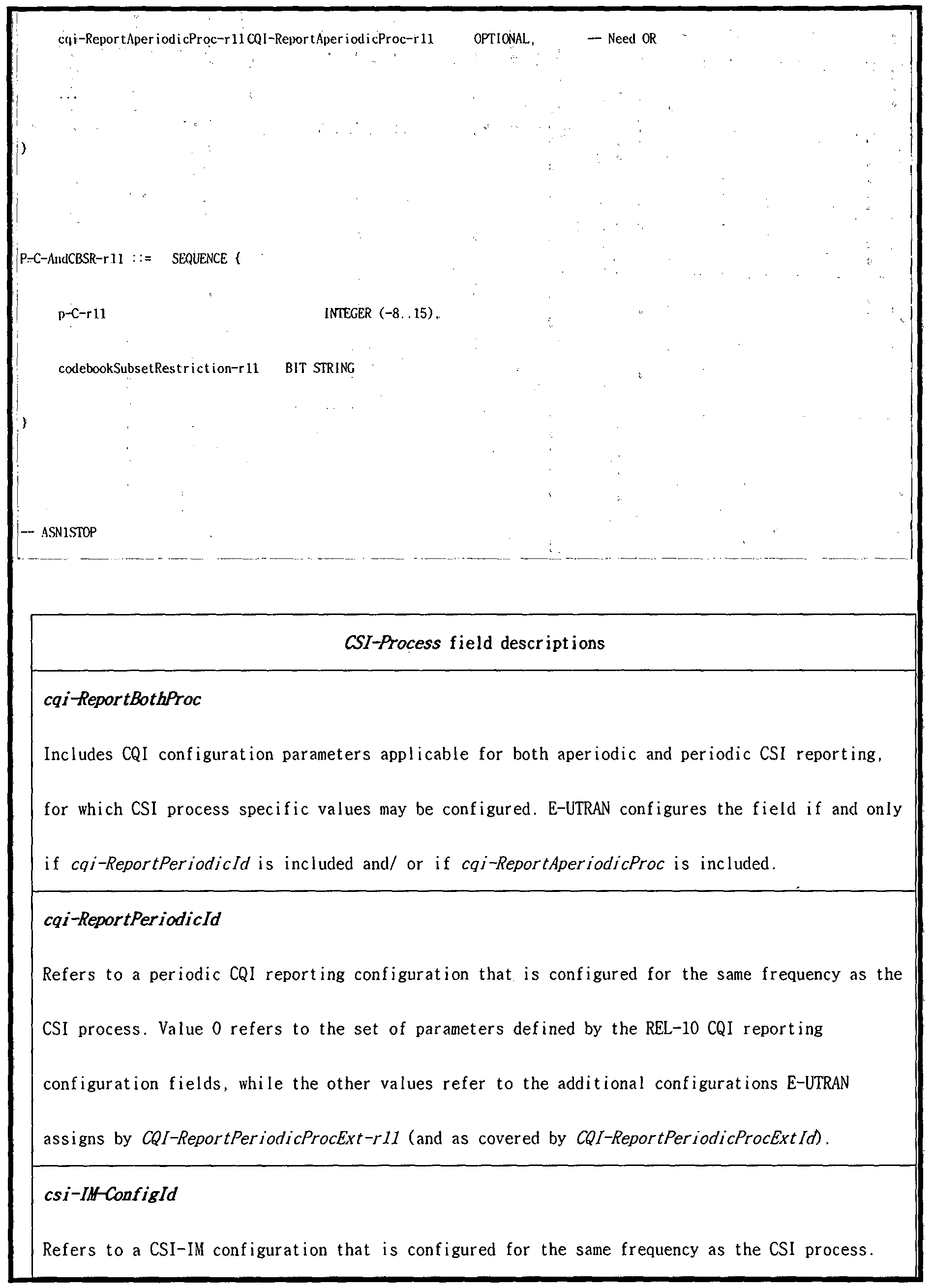
  • the IE CSI-IM-Config is the CSI Interference Measurement (IM) configuration that E-UTRAN may configure on a serving frequency, see TS 36.213 [23, 7.2.6].
  • a pC-AndAn t enna In foDedL is t including 2 entries indicates that the subframe patterns configured for CSI (CQI / PMI / PTI / RI) reporting (ie as defined by field cs i -MeasSubframeSet 1 and csi ⁇ MeasSubframeSet2) are to be used for this CSI process, while a single entry indicates that the subframe patterns are not to be used for this CSI process.
  • E-UTRAN does not include 2 entries in pC-AndAn t enna InfoDedL is t for CSI processes concerning a secondary frequency.
  • E-UTRAN includes 2 entries in p -C-AndAn t enna I n foDedL / st when configuring both cqi-pmi-Confi ' gindex and cqi-pmi- ConfigIndex2.
  • the IE CSI -Process Id is used to identify a CSI process that is configured by the IE CSI -Process.
  • the identity is unique within the scope of a carrier frequency.
  • the IE CSI-RS-Config is used to specify the CSI (Channel-State Information) reference signal configuration.
  • Parameter represents the number of antenna ports used for transmission of CSI reference signals where value anl corresponds to 1 antenna port, an2 to 2 antenna ports and so on, see TS 36.211 [21, 6.10.5].
  • the IE CSI ⁇ RS-ConfigNZP is the CSI-RS resource configuration using non-zero power transmission that E-UTRAN may configure on a serving frequency.
  • Parameter represents the number of antenna ports used for transmission of CSI reference signals where anl corresponds to 1 , an2 to 2 antenna ports etc. see TS 36.211 [21, 6.10.5].
  • the IE CSI ⁇ RS ⁇ Conf igNZPId is used to identify a CSI-RS resource configuration using non-zero transmission power t as configured by the IE CS I ⁇ RS ⁇ Con fi gNZP.
  • the identity is unique within the scope of a carrier frequency.
  • the IE CSI-RS-ConfigZPId is used to identify a CSI-RS resource configuration for which UE assumes zero transmission power, as configured by the IE CSI-RS ⁇ Conf igZP.
  • the identity is unique within the scope of a carrier frequency.
  • CSI-IM Resource Conf igurat ion shows an example of how to set / define.
  • Table 5 may be limitedly applied only to a terminal operating in TM 10.
  • One Re 1-12 CSI—IM resource is defined to contain up; to two Rel-11 CSI—IM resources, i.e. one or two sets of ⁇ resourceConfig, subframeConfig [3]
  • One Re 1-12 CSI process is defined to contain up to two CSI—IM resources, ie one or two CSI-IM ⁇ Conf igld [3]
  • [Alt # 2] in Table 5 configures up to two CSI-IM Resource Configurations on one CSI process, but each 'CSI-IM Resource Configuration' has one ⁇ resourceConfig, subframingConig ig. ⁇
  • up to two CSI-IM Resource Configurations configured on one CSI process may have different CSI-IM-Conf iglds (ie, see CSI-IM-Configld IE in Table 4). do.
  • Embodiments of the present invention described below are effective when ZP CSI-RS Resource Conf igurat (s) is applied when the new CSI-IM Resource Conf igurat ion (s) settings / definitions of Table 5 are applied. It explains how to set / define. All In other words, the following embodiments, ZP CSI-RS Resource Conf iguration for efficiently covering / overlapping (in terms of PDSCH Rate Matching) resource areas in which the new CSI-IM Resource Configuration (s) based on Table 5 appear (s) relates to settings / definitions.
  • One ZP CSI-RS Resource Configuration (e.g., can be interpreted as Re ⁇ 12 ZP CSI-RS Resource Configuration) differs from the existing (i.e., only one ⁇ resourceConf igList subframeConfig ⁇ is defined).
  • resourceConf igList, subframeConfig ⁇ (ie, CSI-RS— Refer to Conf igZP IE in Table 4).
  • up to two ZP CSI-RS Resource Configurations having different periods / offsets (and / black are RE positions) are defined through one ZP CSI-RS Resource Configuration configuration.
  • the first scheme is that a single CSI-IM Resource Configuration configured on one CSI process is different from the existing (that is, when only one ⁇ resourceConf ig, subframeConfig ⁇ is defined), and at most two ⁇ resourceConf ig,-subf rameConf ig ⁇ (that is, CSI-IM-Conf ig IE of Table 4) may be set to be applied only if limited. Therefore, specifically illustrating the case where the first room is applied, it is shown in Table 6.
  • resourceConf igList (1) BIT STRING (SIZE (16)),
  • subframeConfig (1) INTEGER (0.:154), resourceConf igList (2) BIT STRING (SIZE (16)),
  • one ZP CSI-RS Resource Configuration may be set to be defined as shown in Table 6.
  • Table 7 interprets that one ZP CSI-RS Resource Conf igurat ion is defined as a maximum of two ⁇ resourceConf igList, subframeConf ig (1)>, ⁇ resourceConf igList, subframeConf ig (2) ⁇ , that is, resourceConf igList Are common and only subframeConf ig can be in different forms).
  • one ZP CSI-RS Resource Configuration ⁇ up to two ⁇ resourceConf igList (1), subframeConf ig ⁇ , ⁇ resourceConf igList (2), subframe Config ⁇ (that is, subframeConf ig is common, and only resourceConf igList may be in a different form).
  • the first method applied for the ZP CSI-RS Resource Configuration may be extended to one NZP CSI-RS Resource Configuration, whereby aperiodic NZP CSI-RS transmission is performed. Can be.
  • the first scheme may be configured to be limitedly applied only to a terminal operating with TM 10.
  • CSI-RS Resource Conf igurat ion (s) (eg, Rel-11 ZP CSI-RS Resource Conf igurat ion (s)) 7 ⁇ .
  • the second scheme may be set to be limitedly applied only to a terminal operating with TM 10.
  • resourceConfigList (2) BIT STRING (SIZE (16)),
  • the terminal operating with TM 1-9 could receive only one ZP CSI-RS Resource Configuration (for a specific cell).
  • a terminal operating in TM 1-9 and a terminal operating in TM 10 may be mixed on a cell operating in a dynamic change mode for radio resource use (ie, an "elMTA-enabled Cell").
  • TM 10 If the UE operating as TM 10 is operated according to i) setting / definition of new CSI-IM Resource Conf igurat ion (s) based on Table 5 described above, and / or black is ii) the first method described above or If a new ZP CSI-RS Resource Configuration ion (s) setting / definition based on the second option is applied, it will operate as TM 1-9 on the corresponding €.
  • the UE transmits a DL downlink resource set (eg, UL SF (s) on SIB 1 UL-DL Conf igurat ion and / or DL SF (s) on RROConf igured DL Reference Conf igurat ion during S SF (s). It is necessary to inform the correct PDSCH RE mapping assumption (and / or EPDCCH RE mapping assumption) in the subframes used).
  • a DL downlink resource set eg, UL SF (s) on SIB 1 UL-DL Conf
  • up to two ZP CSI-RS Resource Conf igurat ions may be configured in a terminal operating with TM 1 to 9.
  • the individual ZP CSI-RS Resource Conf igurat ion eg, zeroTxPower CSI-RS (1) and zeroTxPowerCSI-RS (2) in Table 9
  • the individual ZP CSI-RS Resource Conf igurat ion are defined to have one ⁇ zeroTxPowerResourceConf igList, zeroTxPowerSubframeConf ig ⁇ , respectively. It can also be.
  • such a rule ie, a rule in which up to two ZP CSI-RS Resource Conf igurat ions are set for a terminal operating with TM 1-9) is applied to a terminal operating with TM1 to 9, and the CSI measurement is performed.
  • Or Resource-Speci fic CSI Measurement may be defined to be applied only when it is set.
  • the method operates as TM 1-9 regardless of TM 10 operation operated by the new CSI-IM Resource Conf igurat ion (s) setting / definition method described above. It is possible to inform the UE of the correct PDSCH RE mapping assumption (and / or EPDCCH RE mapping assumption) to the UE.
  • Table 9 shows a case where the third scheme is implemented based on the CSI-RS-Conf ig IE form of Rel-10 in Table 4, and Table 10 shows the CSI-RS-Conf igZP IE form of Re ⁇ 11 in Table 4 above.
  • Table 10 shows the CSI-RS-Conf igZP IE form of Re ⁇ 11 in Table 4 above.
  • An example of the case where the third scheme is implemented (that is, extended to the terminal operating with TM 10) may be shown.
  • resourceConf igList (1) BIT STRING (SIZE (16))
  • a single ZP CSI-RS Resource Conf igurat ion can have up to two ⁇ zeroTxPowerResourceConf igList (1), zeroTxPowerSubf rameConf ig (1) ⁇ , ⁇ z eroTxPowerResourceConf igList (2), zeroTxPowerSubf rameConf ig (2) ⁇ Can be interpreted as.
  • Table 11 shows that up to two ZP CSI-RS Resource Conf igurat ions having different periods (and / black are RE positions) through one ZP CSI-RS Resource Configuration configuration. A defined effect can be obtained.
  • resourceConfigList (2) BIT STRING (SIZE (16)),
  • one ZP CSI-RS Resource Configuration has a maximum of two ⁇ zeroTxPowerResourceConf igList (1), zer oTxPowerSubf rameConf ig ⁇ , ⁇ zeroTxPowerResourceConf igList (2), and zer oTxPowerSubf rameConf ig ⁇
  • the type defined by ⁇ that is, zeroTxPowerSubrameConfig is common, and only zeroTxPowerResourceConfigList may be set to a different type.
  • the third method applied for the ZP CSI-RS Resource Configuration can be extended and applied to one NZP CSI-RS Resource Configuration, whereby the aperiodic NZP CSI-RS transmission implementation is implemented. It becomes possible.
  • the third scheme may be configured to be limitedly applied only to terminals operating with TM 1 to 9.
  • the base station performs PDSCH RE performed in a specific subframe through a PDSCH RE Mapping and Quasi-Co-Locat ion Indicator field (ie, a "PQI field") defined in DCI Format 2D to a UE operating as TM 10. It can tell you the assumptions about the mapping.
  • Table 12 shows all PDSCH resource mapping operations in the existing wireless communication system.
  • up to four ZP CSI-RS Resource Configurations (per Carrier Frequency) can be configured for a UE operating in TM 10.
  • a specific cell operates a radio resource dynamic change mode and a CoMP operation mode (that is, TM 10) at the same time, at least one of the first to third methods described above, at most two ZP CSI-RS Resource Conf iguration (s) is not used for interference measurement for different cells participating in CoMP operation, but is based on the Table 5 above, set up on a specific cell (ie elMTA-enabled Cell).
  • ZP CSI-RS Resource Conf igurat ion (s) can be interpreted as being used for interferometry for a particular cell). Therefore, this use of ZP CSI-RS Resource Conf igurat ion (s) results in a reduction in the performance gain that can be obtained from CoMP operation.
  • a UE configured in transmission mode 10 for a given serving cell can be configured with up to 4 parameter sets by higher layer signaling to decode PDSCH according to a detected PDCCH / EPDCCH with DCI format 2D intended for the UE and the given serving cell.
  • the UE shall use the parameter set according to the value of the 'PDSCH RE Maping and Quasi— CcrLocat ion indicator' field (map ing defined in Table 7.1.9-1) in the detected
  • PDCCH / EPDCCH with DCI format 2D for determining the PDSCH RE mapping (defined in sub-clause 6.4 of [2]), and for determining PDSCH antenna port quasi allocation (defined in sub-clause 7.1.10 [1]) if the UE is
  • Type B quasi allocation type (defined in sub-clause 7.1.10 [1]).
  • the UE shall use the parameter set indicated in the PDCCH / EPDCCH with DCI format 2D
  • Table 7.1.9-1 PDSCH RE Mapping and Quasi -Co-Location Indicator field in DCI format 2D
  • a UE configured in transmission mode 10 for a given serving cell shall use the parameter set 1 in table 7.1.9-1 for determining the PDSCH RE mapping (defined in subclause 6.4 of [2]), and for determining PDSCH antenna port quasi co- location (defined in sub-clause 7.1.10 [1]) if the UE is configured with Type B quasi co-location type (defined in sub-clause 7.1.10 [1]).
  • a UE configured in transmission mode 10 for a given serving cell shall use the parameter set 1 in table 7.1.9-1 for determining the PDSCH RE mapping (defined in sub ⁇ clause 6.4 of [2]), and for determining PDSCH antenna port quasi co-location (defined in sub-clause 7.1.10 [1]) if the UE is configured with Type B quasi co-location type (defined in sub ⁇ clause 7.1.10 [1]).
  • a UE configured in transmission mode 10 for the given serving cell shall determine the PDSCH RE map ing (as described in sub ⁇ clause 6.4 of [2]) using the lowest indexed zero-power CSI-RS resource.
  • two ZP CSI-RS Resource Conf iguration (eg, Rel-11 ZP CSI-RS) in at least one (i.e., some black all) PQI field values are (maximum).
  • Resource Conf iguration may be set through higher layer signals (eg, RRC signaling).
  • at least one (ie some black is all) PQI Two (maximum) ZP CSI-RS Resource Conf igurats set to the field values It may be implemented by at least one of the first to third methods described above.
  • two ZP CSI-RS Resource Conf igurat ion (s) are defined as two independent CSI-RS-Conf igZP (1) and CSI-RS-Conf igZP (2) ( That is, csi-RS-Conf igZPId, resourceConf igList, and subframeConf ig may be set differently).
  • Table 13 shows the case where the proposed proposal 4 is applied.
  • Table 7.1.9-1 PDSCH RE Mappin and Quasi -Co-Locat ion Indicator f ield in DC I format
  • the fol lowing parameters for determining PDSCH RE map ing and PDSCH antenna port quasi co-locat ion are conf igured via higher layer signal ing for each parameter set:
  • a new one ZP CSI-RS Resource Configuration (eg, Re 1-12 ZP CSI-RS) defined in the first scheme described above in at least one (i.e., some black or all) PQI field values. Resource Configuration) may be configured through higher layer signals (eg, RRC signaling).
  • a new ZP CSI-RS Resource Configuration is set (ie, csi-RS-ConfigZPId is one) in at least one (ie, some black and all) PQI field values.
  • csi-RS-ConfigZPId is one
  • PQI field values ie, some black and all
  • the fourth method applied for the ZP CSI-RS Resource Configuration may be extended and applied to one NZP CSI-RS Resource Configuration. Through this, aperiodic NZP CSI-RS transmission may be performed.
  • Table 7.1.9-1 PDSCH RE Maping and Quasi "Co ⁇ Locat ion Indicator field in DCI format
  • the fol lowing parameters for determining PDSCH RE map ing and PDSCH antenna port quasi co-locat ion are conf igured via higher layer signal ing for each parameter set;
  • the fourth scheme may be configured to be limitedly applied only to a terminal operating with TM 10.
  • the UE receives the r e-Mapp i ng QCL-Conf ig I dr 11 parameter for each EPDCCH-PRB-Set through a higher layer signal from the base station.
  • the re-Mapp i ngQCL-Conf igl dr 11 parameter set / signaled for each EPDCCH-PRB-Set is a PDSCH RE mapping assumption (and / or PDSCH Antenna Port Quasi Co-locat ion set for each PQI state described in Table 12). Assumptions) set of related parameters, i.e.
  • the fourth scheme maintains the same re-MappingQCL-Conf igld-rll parameter setting / matching process for each existing EPDCCH-PRB-Set, while not only static downlink resource set but also floating downlink. It will be able to inform the correct EPDCCH RE mapping assumption (and / or EPDCCH Antenna Port Quasi Co-locat ion assumption) of the individual (Conf igured) EPDCCH-PRB-Set on the resource set.
  • At least one of the settings #A to #C described below may be set to apply.
  • ⁇ Configuration #A On one CSI process in the new CSI-IM Resource Conf igurat ion (s) settings / definitions in Table 5 (ie, [Al t # 1], [Al t # 2]). Up to two CSI-IM Resource (s) based on different CSI-IM-Conf iglds and / or up to two ⁇ ResourceConf ig, subframeConf ig ⁇ under the same CSI-IM-Conf igld (s) shall be set so that they do not appear or overlap at the same subframe time point.
  • (two) CSI Subframe Sets are set in the CSI process of the UE (eg, elMTA UE) operating as TM 10, and the UE determines the corresponding CSI Subframe Set related Interference Measurement.
  • CSI-IM in CSI Subframe Set When performing only with Resource (s), this configuration #A is related to a specific CSI Subframe Set at a certain SF time point (for example, any SF time point where CSI-IM Resource exists). You can prevent the Interference Measurement from performing with 8 RE (s).
  • the UE performs an Interference Measurement related to a specific CSI Subframe Set at an arbitrary subframe time point (for example, any SF time point where a CSI-IM Resource exists). It can be done with RE (s).
  • the UE may simultaneously display or overlap up to two CSI-IM Resource based on different CSI-IM-Conf iglds at the same subframe time point. s) may not be expected.
  • the UE may display up to two ⁇ resourceConf ig, under the same CSI-IM-Conf igld that appear or overlap at the same subframe time point. subf rameConf ig ⁇ ⁇ - You may not expect the CSI-IM Resource (s) to be set.
  • ⁇ configuration #B a single CSI in the new CSI-IM Resource Conf igurat ion (s) settings / definitions in Table 5 above (ie, [Al t # 1], [Al t # 2]) Up to two CSI-IM Resource (s) based on different CSI-IM-Conf iglds configured on a process and / or up to two ⁇ resourceConf ig, subframeConf ig ⁇ s under the same CSI-IM-Conf igld If IM Resource (s) appears or overlaps at the same sub-frame time point at the same time, the UE may: i) CSI-IM Resource having a relatively low CSI-IM-Conf igld (ie, [Al t # 1]).
  • Ii) in the case of a CSI-IM Resource i.e., [Alt #l] / [Al t # 2]
  • a CSI-IM Resource i.e., [Alt #l] / [Al t # 2]
  • iii) has a relatively long period e.g, determined by subframeConf ig) Useful
  • iii) only certain CSI-IM Resources defined or signaled in advance are valid.
  • a specific one ZP set to be determined or specified by the PQI field i.e., DCI Format 2D
  • CSI-IM Resource (s) covered by CSI-RS Resource to be valid (e.g., if one particular ZP CSI-RS Resource specified by the PQI field covers only one CSI-IM Resource, If only one CSI-IM Resource is determined to be valid, and if one ZP CSI-RS Resource specified by the PQI field covers two CSI-IM Resources, the two CSI-IM Resources are considered valid. Or (v) set to ensure that a (minimum) ZP CSI-RS Resource that is capable of covering both (maximum) CSI-IM Resources simultaneously or overlapping at the same subframe point is configured. Maximum) When two CSI-IM resources appear or overlap at the same time, the corresponding ZP CSI-RS Resource can be designated as a PQI field.
  • configuration #A and / or configuration #B may correspond to individual CSI-IM resources (based on [Al t # 1] or [Al t # 2]) that appear or overlap at the same time at the same subframe.
  • A) Covered by independent (Conf igured) ZP CSI-RS Resource ie, "A UE is not expected to receive a CSI-IM resource conf igurat ion that is not completely over l pping with one of the zero-power CSI-RS resource conf igurations ions def ined in sub-clause 7.2.7 ", while separate (Conf igured) ZP CSI-RS Resources may appear or overlap (up to This can be useful if you do not cover both CSI-IM resources.
  • the ZP CSI-RS Resource assumed by the UE at the time of the corresponding subframe is a specific ZP CSI-RS Resource indicated by the PQI field (ie, DCI Format 2D).
  • the specific one ZP CSI-RS Resource specified by the PQI field does not cover both (maximum) two CSI-IM Resources (s) that appear or overlap at the same time at the same subframe time point
  • the specific one CSI In at least one (ie, some or all) areas of the IM Resource, data (eg PDSCH) transmission from a serving cell may be performed, and thus, a corresponding subframe.
  • data eg PDSCH
  • interference of the same characteristic on two (maximum) CSI-IM Resources (s) appearing or overlapping at the same time cannot be assumed.
  • the data of the TP is not external interference caused by the QCL characteristic related (elMTA) Transmission Point (TP) specified by the PQI field. Interference due to transmission will appear.
  • QCL characteristic related (elMTA) Transmission Point (TP) specified by the PQI field. Interference due to transmission will appear.
  • ⁇ configuration #C in the above schemes 1 to 4, at least two ZP CSI-RS Resource (s) based on different csi-RS-Conf igZPId and / black are the same csi-RS-Conf Under igZPId, at most two ⁇ resourceConf igList, subframeConf ig ⁇ , ZP CSI-RS Resource (s) should be set not to appear (or overlap) at the same subframe time point. As another example, if these ZP CSI-RS Resource (s) appear or overlap at the same subframe time point, the UE may have a predefined rule (eg, ZP CSI- with a relatively low csi-RS-ConfigZPId).
  • a predefined rule eg, ZP CSI- with a relatively low csi-RS-ConfigZPId.
  • Black determines that only ZP CSI-RS Resource with a relatively long period is valid Black is determined based on a predefined (or signaled) specific ZP CSI-RS Resource only. It may be set to determine that only ZP CSI-RS Resource of is valid.
  • the first to fifth schemes of the present invention described above are the new CSI-IM Resource Conf igurat ion (s) settings / definitions described in Table 5 (ie, [Alt # 1], [Alt #]). 2]) may be set to be applied to only one of the). Alternatively, the first to fifth methods of the present invention described above may be set to be limitedly applied only to a specific TM (for example, TM10 or TM1 to 9).
  • embodiments of the present invention may be configured to be limitedly applied only when the dynamic change mode for radio resource use is set (Conf igurat ion). Furthermore, embodiments of the present invention described above are extended even when radio resource usage change information is set to be transmitted not only through a physical channel signal but also through a predefined system information transmission channel (eg, SIB, PBCH (MIB), PAGING). Application is possible.
  • SIB system information transmission channel
  • MIB PBCH
  • PAGING predefined system information transmission channel
  • the embodiments of the present invention described above may include i) an EPDCCH RE mapping hypothesis, or ii) an EPDCCH Antenna Port Quasi Co-locat ion hypothesis, or iii) a PDSCH RE mapping hypothesis; Or iv) PDSCH Antenna Port Quasi Co-locat ion may be set to be used in a limited manner for setting up at least one of the assumptions.
  • embodiments / settings / rules of the present invention described above may also be judged as one embodiment for carrying out the present invention, and each may be regarded as one independent embodiment. to be.
  • embodiments of the present invention may be implemented independently, but may be implemented in a combination or merged form of some embodiments.
  • FIG. 11 illustrates a base station and user equipment that can be applied to an embodiment of the present invention.
  • a relay is included in the wireless communication system, communication is performed between the base station and the relay in the backhaul link, and communication is performed between the relay and the user equipment in the access link.
  • the base station or user equipment illustrated in the figure may be replaced with a relay according to the situation.
  • a wireless communication system includes a base station (BS) 110 and a user equipment (UE) 120.
  • Base station 110 includes a processor 112, a memory 114, and a radio frequency (RF) unit 116.
  • the processor 112 may be configured to implement the procedures and / or methods proposed in the present invention.
  • the memory 114 is connected with the processor 112 and stores various information related to the operation of the processor 112.
  • the RF unit 116 is connected with the processor 112 and transmits and / or receives a radio signal.
  • the user device 120 includes a processor 122, a memory 124, and an RF unit 126.
  • the processor 122 may implement the procedures and / or methods proposed by the present invention. May be configured.
  • the memory 124 is connected with the processor 122 and stores various information related to the operation of the processor 122.
  • the RF unit 126 is connected with the processor 122 and transmits and / or receives a radio signal.
  • Base station 110 and / or user equipment 120 may have a single antenna or multiple antennas.
  • the embodiment according to the present invention may be implemented by various means, for example, hardware, firmware (i ir ⁇ are), software, or a combination thereof.
  • one embodiment of the present invention may include one or more ASICs (application integrated circuits), digital signal processors (DSPs), digital signal processing devices (DSPDs), and PLDs.
  • ASICs application integrated circuits
  • DSPs digital signal processors
  • DSPDs digital signal processing devices
  • PLDs programmable logic devices
  • FPGAs programmable gate arrays
  • processors controllers, microcontrollers, microprocessors, and the like.
  • an embodiment of the present invention may be implemented in the form of modules, procedures, functions, etc. that perform the functions or operations described above.
  • Software code may be stored in a memory unit and driven by a processor.
  • the memory unit may be located inside or outside the processor, and may exchange data with the processor by various known means.

Abstract

The present invention relates to a method and an apparatus for transmitting, by a base station, a channel state information-reference signal (CSI-RS) configuration in a wireless communication system. Particularly, the method comprises the steps of: forming an information element for configuring a first channel state information (CSI) subframe aggregation and a second CSI subframe aggregation; and transmitting a CSI-RS configuration including at least one zero power(ZP)-CSI-RS configuration, wherein the CSI-RS configuration includes a first ZP-CSI-RS configuration for a first terminal in which the information element is not configured and a second terminal in which the information element is configured; and a second ZP-CSI-RS configuration for only the second terminal.

Description

【명세서】  【Specification】
【발명의 명칭】  [Name of invention]
무선 통신 시스템에서 간섭 측정 자원 설정 방법 및 이를 위한 장치 【기술분야】  Method for setting interference measurement resource in wireless communication system and apparatus therefor
[1] 본 발명은 무선 통신 시스템에 관한 것으로, 보다 구체적으로 무선 통신 시스템에서 간섭 측정 자원 설정 방법 및 이를 위한 장치에 관한 것이다. The present invention relates to a wireless communication system, and more particularly, to a method and apparatus for setting interference measurement resources in a wireless communication system.
【배경기슬 1  Background Backdrop 1
[2] 본 발명이 적용될 수 있는 무선 통신 시스템의 일례로서 3GPP LTE (3rd Generat ion Partnership Project Long Term Evolut ion; 이하 "LTE"라 함) 통신 시스템에 대해 개략적으로 설명한다.  [2] As an example of a wireless communication system to which the present invention can be applied, a 3GPP LTE (3rd Generat ion Partnership Project Long Term Evolut ion (hereinafter referred to as "LTE")) communication system will be described.
[3] 도 1 은 무선 통신 시스템의 일례로서 E-UMTS 망구조를 개략적으로 도시 한도면이다. E-UMTS( Evolved Universal Mobi le Telecommunicat ions System) 시 스템은 기존 UMTS(Universal Mobi le Telecommuni cat ions System)에서 진화한 시 스템으로서, 현재 3GPP 에서 기초적인 표준화 작업을 진행하고 있다. 일반적으 로 E-UMTS 는 LTE(Long Term Evolut ion) 시스템이라고 할 수도 있다. UMTS 및 E-UMTS 의 기술 규격 (technical speci f i cat ion)의 상세한 내용은 각각 "3rd Generat ion Partnership Project; Techni cal Speci f i cat ion 그룹 Radio Access Network"의 Release 7과 Release 8을 참조할수 있다.  1 is a diagram schematically illustrating an E-UMTS network structure as an example of a wireless communication system. The Evolved Universal Mobility Telecommunication Systems (E-UMTS) system is an evolution from the existing Universal Mobility Telecommuni ions System (UMTS), and is currently undergoing basic standardization work in 3GPP. In general, E-UMTS may be referred to as a Long Term Evolut ion (LTE) system. For details of the technical specifications of UMTS and E-UMTS, see Release 7 and Release 8 of the "3rd Generat ion Partnership Project; Technical Speci- cation Group Radio Access Network", respectively.
[4] 도 1 을 참조하면, E-UMTS는 단말 (User Equipment ; UE)과 기지국 (eNode B; eNB) , 네트워크 (E-UTRAN)의 종단에 위치하여 외부 네트워크와 연결되는 접속 게이트웨이 (Access Gateway; AG)를 포함한다. 기지국은 브로드캐스트 서비스, 멀티캐스트 서비스 및 /또는 유니캐스트서비스를 위해 다증 데이터 스트림을 동 시에 전송할 수 있다.  [4] Referring to FIG. 1, an E-UMTS is located at an end of a user equipment (UE), a base station (eNode B; eNB), and a network (E-UTRAN) and connected to an external network (Access Gateway). AG). The base station may transmit multiple data streams simultaneously for broadcast service, multicast service and / or unicast service.
[5] 한 기지국에는 하나 이상의 샐이 존재한다. 셀은 1.44, 3 , 5, 10, 15, 20Mhz 등의 대역폭 중 하나로 설정돼 여러 단말에게 하향 또는 상향 전송 서비 스를 제공한다. 서로 다른 샐은서로 다른 대역폭을 제공하도록 설정될 수 있다. 기지국은 다수의 단말에 대한 데이터 송수신올 제어한다. 하향 링크 (Downl ink; [5] One or more cells exist in one base station. The cell is set to one of the bandwidths of 1.44, 3, 5, 10, 15, 20Mhz, etc. to provide downlink or uplink transmission services to multiple terminals. Different cells can be set to provide different bandwidths. The base station controls data transmission and reception for a plurality of terminals. Downlink (Downl ink;
DL) 데이터에 대해 기지국은 하향 링크 스케줄링 정보를 전송하여 해당 단말에 게 데이터가 전송될 시간 /주파수 영역, 부호화, 데이터 크기, HARQ Hybr id Automat i c Repeat and reQuest ) 관련 정보 등을 알려준다. 또한, 상향 링크 (Upl ink; UL) 데이터에 대해 기지국은 상향 링크 스케줄링 정보를 해당 단말에 게 전송하여 해당 단말이 사용할 수 있는 시간 /주파수 영역, 부호화, 데이터 크 기, HARQ 관련 정보 등을 알려준다. 기지국간에는 사용자 트래픽 또는 제어 트 래픽 전송을 위한 인터페이스가 사용될 수 있다. 핵심망 (Core Network; CN)은 AG와 단말의 사용자등록 등을 위한 네트워크 노드 등으로 구성될 수 있다. AG 는 복수의 셀들로 구성되는 TA Tracking Area) 단위로 단말의 이동성을 관리한 다. For DL) data, the base station transmits downlink scheduling information to inform the corresponding terminal of time / frequency domain, encoding, data size, HARQ hybr id Automat ic Repeat and reQuest) related information. In addition, uplink For uplink (UL) data, the base station transmits uplink scheduling information to the terminal to inform the user of the time / frequency domain, encoding, data size, HARQ-related information, and the like. An interface for transmitting user traffic or control traffic may be used between base stations. The core network (CN) may consist of an AG and a network node for user registration of the terminal, and the like. The AG manages the mobility of the UE in units of a TA Tracking Area composed of a plurality of cells.
[6] 무선 통신 기술은 WCDMA를 기반으로 LTE까지 개발되어 왔지만, 사용자 와 사업자의 요구와 기대는 지속적으로 충가하고 있다. 또한, 다른 무선 접속 기술이 계속 개발되고 있으므로 향후 경쟁력을 가지기 위해서는 새로운 기술 진 화가요구된다. 비트당 비용 감소, 서비스 가용성 증대, 융통성 있는 주파수 밴 드의 사용, 단순구조와 개방형 인터페이스, 단말의 적절한 파워 소모등이 요구 된다.  [6] Wireless communication technology has been developed up to LTE based on WCDMA, but the demands and expectations of users and operators continue to be met. In addition, as other radio access technologies continue to be developed, new technological advances are required to be competitive in the future. Reduced cost per bit, increased service availability, flexible use of frequency bands, simple structure and open interface, and adequate power consumption of the terminal are required.
【발명의 상세한 설명】  [Detailed Description of the Invention]
【기술적 과제】  [Technical problem]
[7] 본 발명의 목적은 무선 통신 시스템에서 간섭 측정 자원 설정 방법 및 이를 위한 장치를 제공하는 데 있다.  An object of the present invention is to provide an interference measurement resource setting method and apparatus therefor in a wireless communication system.
[8] 본 발명에서 이루고자 하는 기술적 과제들은 상기 기술적 과제로 제한되 지 않으며, 언급하지 않은 또 다른 기술적 과제들은 아래의 기재로부터 본 발명 이 속하는 기술분야에서 통상의 지식을 가진 자에게 명확하게 이해될 수 있을 것이다.  [8] The technical problems to be achieved in the present invention are not limited to the above technical problems, and other technical problems not mentioned will be clearly understood by those skilled in the art from the following description. Could be.
【기술적 해결방법】  Technical Solution
[9] 상술한 문제점을 해결하기 위한 본 발명의 일 양상인, 무선 통신 시스템 에서 기지국이 채널상태정보-참조신호 (Channel State Informat ion-Reference Signal , CSI-RS) 설정올 송신하는 방법은, 제 1 채널상태정보 (Channel State Informat ion, CSI ) 서브프레임 집합과 제 2 채널상태정보 (CSI ) 서브프레임 집합 을 설정하는 정보 요소 ( Informat ion Element)를 구성하는 단계; 및 적어도 하나 의 ZP-CSI-RS 설정 (Zero Power CSI-RS conf igurat ion)올 포함하는 CSI-RS 설정 을 송신하는 단계를 포함하며, 상기 CSI-RS 설정은, 상기 정보요소가 설정되지 않는 제 1 단말과상기 정보 요소가설정되는 제 2 단말을 위한 제 1 ZP-CSI-RS 설정 및 상기 제 2 단말만을 위한 제 2 ZP-CSI-RS설정을 포함하는 것을 특징으 로 한다. [9] A method of transmitting a channel state information-reference signal (CSI-RS) by a base station in a wireless communication system, which is an aspect of the present invention for solving the above problems, is described in detail. Constructing an information element (Informat ion Element) for setting a first channel state information (CSI) subframe set and a second channel state information (CSI) subframe set; And transmitting a CSI-RS configuration including at least one ZP-CSI-RS configuration, wherein the CSI-RS configuration comprises: the information element not being set; First ZP-CSI-RS for a first terminal and a second terminal for which the information element is set And a second ZP-CSI-RS configuration for only the second terminal.
[10] 나아가, 상기 제 1 단말은, 전송 모드 1 내지 전송 모드 9 기반 단말이 며,  [10] Furthermore, the first terminal is a transmission mode 1 to transmission mode 9 based terminal.
[11] 상기 제 2 단말은, 상기 정보 요소에 따라상기 제 1 CSI 서브프레임 집 합 및 상기 제 2 CSI 서브프레임 집합에 기반하여 CSI 측정을 수행하는, 전송 모드 1 내지 전송 모드 9 기반 단말인 것을 특징으로 할수 있다. [11] The second terminal is a transmission mode 1 to transmission mode 9 based terminal that performs CSI measurement based on the first CSI subframe set and the second CSI subframe set according to the information element. Can be characterized.
[12] 나아가, 상기 제 1 ZP-CSI-RS설정 및 상기 제 2 ZP-CSI-RS설정을 위한, zeroTxPowerResourceConf igLi st 파라미터 및 zeroTxPowerSubf rameConf ig 파라미 터는 서로 독립적으로 정의되는 것을 특징으로 할수 있다. In addition, the zeroTxPowerResourceConfigst parameter and the zeroTxPowerSubfRAMConfig parameter for the first ZP-CSI-RS configuration and the second ZP-CSI-RS configuration may be defined independently of each other.
[13] 나아가, 상기 제 1 CSI 서브프레임 집합과상기 제 2 CSI 서브프레임 집 합에 기반한 채널상태정보를 보고받는 단계를 더 포함하는 것을 특징으로 할수 있다. 더 나아가, 상기 제 1 CSI 서브프레임 집합과 상기 제 2 CSI 서브프레임 집합은, 제한된 채널상태정보 측정 서브프레임 집합 (Restr icted CSI measurement subfrarae set)인 것올 특징으로 할 수 있다.  Furthermore, the method may further include reporting channel state information based on the first CSI subframe set and the second CSI subframe set. In addition, the first CSI subframe set and the second CSI subframe set may be characterized in that the limited CSI measurement subframe set (Restr icted CSI measurement subfrarae set).
[14] 상술한 문제점을 해결하기 위한 본 발명의 다른 양상인, 무선 통신 시스 템에서 단말이 채널상태정보 (Channel State Informat ion, CSI )를 보고하는 방법 은, 제 1 채널상태정보 (Channel State Informat ion, CSI ) 서브프레임 집합과 제 2 채널상태정보 (CSI ) 서브프레임 집합을 설정하는 정보 요소 ( Informat ion Element)를 수신하는 단계; 및 적어도 하나의 ZP-CSI-RS 설정 (Zero Power CSI- RS conf igurat ion)을 포함하는 CSI— RS 설정을 수신하는 단계를 포함하며, 상기 CSI-RS 설정은, 제 1 ZP-CSI-RS 설정 및 상기 정보 요소가 설정될 때 적용되는 제 2 ZP-CSI-RS설정을 포함하는 것을 특징으로 할수 있다.  In another aspect of the present invention for solving the above-described problem, a method for a terminal to report channel state information (CSI) in a wireless communication system includes: first channel state information (Channel State Informat); receiving an Informat ion Element for setting the CSI subframe set and the second CSI subframe set; And receiving a CSI-RS configuration including at least one ZP-CSI-RS configuration, wherein the CSI-RS configuration comprises: a first ZP-CSI-RS configuration; And a second ZP-CSI-RS setting applied when the information element is set.
[15] 나아가, 상기 제 1 ZP-CSI-RS 설정은, 전송 모드 1 내지 전송 모드 9 기 반 단말을 위하여 정의되며, 상기 제 2 ZP-CSI-RS설정은, 상기 정보 요소에 따 라, 상기 제 1 CSI 서브프레임 집합 및 상기 제 2 CSI 서브프레임 집합에 기반 하여 CSI 측정을 수행하는, 전송 모드 1 내지 전송 모드 9 기반 단말을 위하여 정의된 것올 특징으로 할수 있다. Further, the first ZP-CSI-RS configuration is defined for a transmission mode 1 to transmission mode 9 based terminal, and the second ZP-CSI-RS configuration is determined according to the information element. It may be characterized in that it is defined for transmission mode 1 to transmission mode 9 based UE performing CSI measurement based on the first CSI subframe set and the second CSI subframe set.
[16] 상술한 문제점을 해결하기 위한 본 발명의 또 다른 양상인, 무선 통신 시스템에서 채널상태정보-참조신호 (Channel State Informat ion-Reference Signal , CSI-RS) 설정을 송신하는 기지국은, 무선 주파수 유닛 (Radio frequency uni t ) ; 및 프로세서 (processor)를 포함하며, 상기 프로세서는, 제 1 채널상태정 보 (Channel State Informat ion, CSI) 서브프레임 집합과 제 2 채널상태정보 (CSI ) 서브프레임 합을 설정하는 정보 요소 ( Informat ion Element)를 구성하며, 적어 도 하나의 ZP-CSI-RS 설정 (Zero Power CSI-RS conf igurat ion)을 포함하는 CSI- RS 설정을 송신하도톡 구성되며, 상기 CSI-RS설정은, 상기 정보 요소가 설정되 지 않는 제 1 단말과 상기 정보 요소가 설정되는 제 2 단말을 위한 제 1 ZP- CSI-RS설정 및 상기 제 2 단말만을 위한 제 2 ZP-CSI-RS설정을 포함하는 것을 특징으로 한다. Channel State Informat ion-Reference signal in a wireless communication system, which is another aspect of the present invention for solving the above problems. The base station for transmitting the signal, CSI-RS) setting includes: a radio frequency unit (Radio frequency unit); And a processor, wherein the processor comprises: an information element for setting a sum of a first channel state information (CSI) subframe set and a second channel state information (CSI) subframe sum; And transmit the CSI-RS settings including at least one ZP-CSI-RS configuration (Zero Power CSI-RS conf igurat ion), wherein the CSI-RS configuration includes: And a first ZP-CSI-RS configuration for the first terminal that is not set and the second terminal for which the information element is set, and a second ZP-CSI-RS configuration for the second terminal only.
[17] 상술한 문제점을 해결하기 위한 본 발명의 또 다른 양상인, 무선 통신 시스템에서 채널상태정보 (Channel State Informat ion, CSI )를 보고하는 단말은, 무선 주파수 유닛 (Radio frequency uni t ) ; 및 프로세서 (processor)를 포함하며, 상기 프로세서는, 제 1 채널상태정보 (Channel State Informat ion, CSI ) 서브프 레임 집합과 제 2 채널상태정보 (CSI ) 서브프레임 집합을 설정하는 정보 요소 ( Informat ion Element )를 수신하며, 적어도 하나의 ZP-CSI-RS 설정 (Zero Power CSI-RS conf igurat ion)을 포함하는 CSI-RS 설정을 수신하도록 구성되고 , 상기 CSI-RS 설정은, 제 1 ZP-CSI-RS 설정 및 상가 정보 요소가 설정될 때 적용되는 제 2 ZP-CSI-RS설정올 포함하는 것을 특징으로 한다. In another aspect of the present invention for solving the above problems, a terminal for reporting channel state information (CSI) in a wireless communication system includes: a radio frequency unit (Radio frequency unit); And a processor, wherein the processor comprises: an information element for setting a first channel state information (CSI) subframe set and a second channel state information (CSI) subframe set And receive a CSI-RS configuration comprising at least one ZP-CSI-RS configuration (Zero Power CSI-RS conf igurat ion), wherein the CSI-RS configuration comprises: a first ZP-CSI-RS configuration; And a second ZP-CSI-RS configuration, which is applied when the RS configuration and store information element is configured.
【유리한 효과】  Advantageous Effects
[18] 본 발명에 의하면, 무선 통신 시스템에서 시스템 부하에 따라 무선 자원 을 동적으로 변경하는 경우에 있어서, 간섭 측정 자원 설정올 효율적으로 수행 할수 있다. According to the present invention, in the case of dynamically changing radio resources according to system load in a wireless communication system, interference measurement resource setting can be efficiently performed.
[19] 본 발명에서 얻은 수 있는 효과는 이상에서 언급한 효과들로 제한되지 않으며, 언급하지 않은 또 다른 효과들은 아래의 기재로부터 본 발명이 속하는 기술분야에서 통상의 지식을 가진 자에게 명확하게 이해될 수 있을 것이다. 【도면의 간단한 설명】  [19] Effects obtained in the present invention are not limited to the above-mentioned effects, and other effects not mentioned above are clearly understood by those skilled in the art from the following description. Could be. [Brief Description of Drawings]
[20] 본 발명에 관한 이해를 돕기 위해 상세한 설명의 일부로 포함되는, 첨부 도면은 본 발명에 대한실시예를 제공하고, 상세한 설명과 함께 본 발명의 기술 적 사상을 설명한다.  The accompanying drawings, which are included as a part of the detailed description to help understand the present invention, provide an embodiment of the present invention and together with the description, describe the technical idea of the present invention.
[21] 도 1은 무선 통신 시스템의 일례로서 E-UMTS 망구조를 나타낸다. [22] 도 2 는 3GPP 무선 접속망 규격을 기반으로 한 단말과 E-UTRAN 사이의 무선 인터페이스 프로토콜 (Radio Interface Protocol)의 제어평면 (Control Plane) 및 사용자평면 (User Plane) 구조를 나타낸다. 1 illustrates an E-UMTS network structure as an example of a wireless communication system. 2 illustrates a control plane and a user plane structure of a radio interface protocol between a terminal and an E-UTRAN based on the 3GPP radio access network standard.
[23] 도 3 은 3GPP LTE 시스템에 이용되는 물리 채널들 및 이들을 이용한 일 반적인 신호 전송 방법올 나타낸다.  3 shows physical channels used in a 3GPP LTE system and a general signal transmission method using the same.
[24] 도 4는 LTE시스템에서 사용되는 무선 프레임의 구조를 나타낸다.  4 shows a structure of a radio frame used in an LTE system.
[25] 도 5는 하향링크 슬롯에 대한자원 그리드 (resource grid)를 나타낸다. 5 shows a resource grid for a downlink slot.
[26] 도 6은 하향링크서브프레임의 구조를 예시한다. 6 illustrates a structure of a downlink subframe.
[27] 도 7은 LTE에서 사용되는 상향링크서브프레임의 구조를 나타낸다. 7 shows a structure of an uplink subframe used in LTE.
[28] 도 8은 CoMP를 수행하는 일 예를 나타낸다. 8 shows an example of performing CoMP.
[29] 도 9 는 TDD 시스템 환경하에서 기존 상향링크 자원의 일부를 하향링크 통신 목적으로 변경하여 이용하는 경우를 나타낸다.  FIG. 9 illustrates a case in which part of an existing uplink resource is changed and used for downlink communication purpose in a TDD system environment.
[30] 도 10 은 TDD 시스템 환경 하에서 각각의 샐들이 자신의 시스템 부하상 태에 따라 기존 무선 자원의 용도를 동적으로 변경할 경우, 외부로부터 수신되 는 간섭 특성이 서브프레임 (혹은서브프레임 집합) 별로 다른 경우를 나타낸다.  [30] FIG. 10 shows that when each cell dynamically changes the use of an existing radio resource according to its system load state, the interference characteristics received from the outside are determined for each subframe (or subframe set) in the TDD system environment. Another case is shown.
[31] 도 11 은 본 발명의 실시예에 적용될 수 있는 기지국 및 사용자 기기를 예시한다. [31] Figure 11 illustrates a base station and user equipment that can be applied to an embodiment of the present invention.
【발명의 실시를 위한 형태】  [Form for implementation of invention]
[32] 이하의 기술은 CDMA(code division multiple access), FDMA( frequency division multiple access) , TDMA(time division multiple access) , 0FDMA( orthogonal frequency division multiple access) , SC-FDMA( single carrier frequency division multiple access) 등과 같은 다양한 무선 접속 시 스템에 사용될 수 있다. CDMA 는 UTRACUniversal Terrestrial Radio Access)나 CDMA2000 과 같은 무선 기술 (radio technology)로 구현될 수 있다. TDMA 는 GSM(Global System for Mobi le communicat ions)/GPRS(General Packet Radio Service) /EDGE (Enhanced Data Rates for GSM Evolution)와 같은 무선 기술로 구 현될 수 있다. 0FDMA는 IEEE 802.11 (Wi-Fi), IEEE 802.16 (WiMAX), IEEE 802- 20, E-UTRA(Evolved UTRA) 등과 같은 무선 기술로 구현될 수 있다. UTRA 는 UMTSCUniversal Mobile Teleco瞧 unications System)의 일부이다. 3GPP(3rd Generation Partnership Project) LTE (long term evolution)는 E—UTRA 를 사용 하는 E-UMTS( Evolved UMTS)의 일부로서 하향링크에서 0FDMA를 채용하고 상향링 크에서 SC-FDMA를 채용한다. LTE-A (Advanced)는 3GPP LTE의 진화된 버전이다. [33] 설명을 명확하게 하기 위해, 3GPP LTE/LTE-A 를 위주로 기슬하지만 본 발명의 기술적 사상이 이에 제한되는 것은 아니다. 또한, 이하의 설명에서 사용 되는 특정 (特定) 용어들은 본 발명의 이해를 돕기 위해서 제공된 것이며, 이러 한 특정 용어의 사용은 본 발명의 기술적 사상올 벗어나지 않는 범위에서 다른 형태로 변경될 수 있다. [32] The following techniques include code division multiple access (CDMA), frequency division multiple access (FDMA), time division multiple access (TDMA), orthogonal frequency division multiple access (0FDMA), and single carrier frequency division multiple access (SC-FDMA). It can be used in various wireless access systems such as). CDMA may be implemented by a radio technology such as UTRACUniversal Terrestrial Radio Access) or CDMA2000. TDMA can be implemented with wireless technologies such as Global System for Mobility Communications (GSM) / General Packet Radio Service (GPRS) / Enhanced Data Rates for GSM Evolution (EDGE). 0FDMA may be implemented by a wireless technology such as IEEE 802.11 (Wi-Fi), IEEE 802.16 (WiMAX), IEEE 802-20, Evolved UTRA (E-UTRA), or the like. UTRA is part of the UMTSCUniversal Mobile Telecom unications System. 3rd Generation Partnership Project (3GPP) long term evolution (LTE) uses E—UTRA As part of the E-UMTS (Evolved UMTS), 0FDMA is adopted in the downlink and SC-FDMA is adopted in the uplink. LTE-A (Advanced) is an evolution of 3GPP LTE. [33] For clarity, the present invention focuses on 3GPP LTE / LTE-A, but the technical spirit of the present invention is not limited thereto. In addition, specific terms used in the following description are provided to help the understanding of the present invention, and the use of such specific terms may be changed to other forms without departing from the technical spirit of the present invention.
[34] 도 2 는 3GPP 무선 접속망 규격을 기반으로 한 단말과 E JTRAN 사이의 무선 인터페이스 프로토콜 (Radio Interface Protocol )의 제어평면 (Control Plane) 및 사용자평면 (User Pl ane) 구조를 나타내는 도면이다. 제어평면은 단말 (User Equipment ; UE)과 네트워크가 호를 관리하기 위해서 이용하는 제어 메시 지들이 전송되는 통로를 의미한다. 사용자평면은 애플리케이션 계층에서 생성된 데이터, 예를 들어, 음성 데이터 또는 인터넷 패킷 데이터 둥이 전송되는 통로 를 의미한다.  FIG. 2 is a diagram illustrating a control plane and a user plane structure of a radio interface protocol between a terminal and an E JTRAN based on the 3GPP radio access network standard. The control plane refers to a path through which control messages used by a user equipment (UE) and a network to manage a call are transmitted. The user plane refers to a path through which data generated at an application layer, for example, voice data or Internet packet data, is transmitted.
[35] 제 1 계층인 물리계층은 물리채널 (Phys i cal Channel )을 이용하여 상위 계층에게 정보 전송서비스 ( Informat ion Transfer Servi ce)를 제공한다. 물리계 층은 상위에 있는 매체접속제어 (Medium Access Control ) 계층과는 전송채널 (Trans 안테나 포트 Channel )을 통해 연결되어 있다. 상기 전송채널을 통해 매 체접속제어 계층과 물리계층 사이에 데이터가 이동한다. 송신측과 수신측의 물 리계층사이는 물리채널을 통해 데이터가 이동한다. 상기 물리채널은 시간과주 파수를 무선 자원으로 활용한다. 구체적으로, 물리채널은 하향 링크에서 0FDMA(0rthogonal Frequency Divi s ion Mul t iple Access) 방식으로 변조되고, 상 향 링크에서 SC-FDMA( Single Carr ier Frequency Divi s ion Mul t iple Access) 방 식으로 변조된다. The physical layer, which is the first layer, provides an information transfer service (Informat ion Transfer Service) to a higher layer by using a physical channel. The physical layer is connected to the upper medium access control layer through a trans antenna port channel. Data is moved between the media access control layer and the physical layer through the transport channel. Data moves between the physical layer at the transmitting and receiving physical layers. The physical channel utilizes time and frequency as radio resources. Specifically, the physical channel is modulated by 0rthogonal frequency diversity mult access (0FDMA) on the downlink, and modulated by single carrier frequency diversity access (SC-FDMA) on the uplink. do.
[36] 제 2 계층의 매체접속제어 (Medium Access Control ; MAC) 계층은 논리채 널 (Logi cal Channel )을통해 상위계층인 무선링크제어 (Radio Link Control ; RLC) 계층에 서비스를 제공한다. 제 2 계층의 RLC 계층은 신뢰성 있는 데이터 전송을 지원한다. RLC 계층의 기능은 MAC 내부의 기능 블록으로 구현될 수도 있다. 제 2 계층의 PDCPCPacket Data Convergence Protocol ) 계층은 대역폭이 좁은 무선 인터페이스에서 IPv4나 IPv6와 같은 IP패킷을 효율적으로 전송하기 위해 불필 요한 제어정보를 줄여주는 헤더 압축 (Header Compression) 기능을 수행한다. [0036] The second layer medium access control (MAC) layer provides a service to a radio link control (RLC) layer, which is a higher layer, through a logical channel. The RLC layer of the second layer supports reliable data transmission. The function of the RLC layer may be implemented as a functional block inside the MAC. The PDCPCPacket Data Convergence Protocol (PDCPC) layer of the second layer has a narrow bandwidth. It performs header compression function to reduce unnecessary control information for efficient transmission of IP packets such as IPv4 or IPv6 in the interface.
[37] 제 3 계층의 최하부에 위치한 무선 자원제어 (Radio Resource Control; RRC) 계층은 제어평면에서만 정의된다. RRC 계층은 무선베어러 (Radio Bearer; RB)들의 설정 (Configuration), 재설정 (Re-configuration) 및 해제 (Release)와 관련되어 논리채널, 전송채널 및 물리채널들의 제어를 담당한다. RB 는 단말과 네트워크 간의 데이터 전달을 위해 제 2 계층에 의해 제공되는서비스를 의미한 다. 이를 위해, 단말과 네트워크의 RRC 계층은서로 RRC메시지를 교환한다ᅳ 단 말과 네트워크의 RRC 계층 사이에 RRC 연결 (RRC Connected)이 있을 경우, 단말 은 RRC 연결 상태 (Connected Mode)에 있게 되고, 그렇지 못할 경우 RRC휴지 상 태 (Idle Mode)에 있게 된다. RRC 계층의 상위에 있는 NAS( Non-Access Stratum) 계층은 세션 관리 (Session Management)와 이동성 관리 (Mobility Management ) 등 의 기능을 수행한다. A radio resource control (RRC) layer located at the bottom of the third layer is defined only in the control plane. The RRC layer is responsible for controlling logical channels, transport channels, and physical channels in association with configuration, reconfiguration, and release of radio bearers (RBs). RB means a service provided by the second layer for data transmission between the terminal and the network. To this end, the RRC layer of the terminal and the network exchanges RRC messages with each other. If there is an RRC connected between the terminal and the RRC layer of the network, the terminal is in an RRC connected mode. If not, the RRC is in Idle Mode. The NAS (Non-Access Stratum) layer above the RRC layer performs functions such as session management and mobility management.
[38] 기지국 (eNB)올 구성하는 하나의 셀은 1.4, 3, 5, 10, 15, 20Mhz 등의 대 역폭 중 하나로 설정되어 여러 단말에게 하향 또는 상향 전송 서비스를 제공한 다. 서로 다른 셀은서로 다른 대역폭을 제공하도록 설정될 수 있다.  One cell constituting the base station (eNB) is set to one of the bandwidths of 1.4, 3, 5, 10, 15, 20Mhz, etc. to provide downlink or uplink transmission service to various terminals. Different cells can be configured to provide different bandwidths.
[39] 네트워크에서 단말로 데이터를 전송하는 하향 전송채널은 시스템 정보를 전송하는 BCH(Broadcast Channel), 페이징 메시지를 전송하는 PCH(Paging Channel), 사용자 트래픽이나 제어 메시지를 전송하는 하향 SCH(Shared Channel) 등이 있다. 하향 멀티캐스트 또는 방송서비스의 트래픽 또는 제어 메시지의 경 우 하향 SCH 를 통해 전송될 수도 있고, 또는 별도의 하향 MCH(Multicast Channel)을 통해 전송될 수도 있다. 한편, 단말에서 네트워크로 데이터를 전송 하는 상향 전송채널로는 초기 제어 메시지를 전송하는 RACH(Random Access Channel), 사용자 트래픽이나 제어 메시지를 전송하는 상향 SCH(Shared Channel) 가 있다. 전송채널의 상위에 있으며, 전송채널에 매핑되는 논리채널 (Logical Channel)로는 BCCH(Broadcast Control Channel), PCCH(Paging Control Channel), CCCH(Co隱 on Control Channel), MCCH(Mult icast Control Channel), MTCH(Multicast Traffic Channel) 등이 있다.  A downlink transport channel for transmitting data from a network to a terminal includes a broadcast channel (BCH) for transmitting system information, a paging channel (PCH) for transmitting a paging message, and a downlink shared channel (SCH) for transmitting user traffic or a control message. ). Traffic or control messages of a downlink multicast or broadcast service may be transmitted through a downlink SCH or may be transmitted through a separate downlink multicast channel (MCH). Meanwhile, the uplink transmission channel for transmitting data from the terminal to the network includes a random access channel (RAC) for transmitting an initial control message and an uplink shared channel (SCH) for transmitting user traffic or a control message. It is located above the transport channel, and the logical channel mapped to the transport channel is BCCH (Broadcast Control Channel), PCCH (Paging Control Channel), CCCH (Co 隱 on Control Channel), MCCH (Mult icast Control Channel), MTCH (Multicast Traffic Channel).
[40] 도 3 은 3GPP LTE 시스템에 이용되는 물리 채널들 및 이들을 이용한 일 반적인 신호 전송 방법을 설명하기 위한 도면이다. [41] 전원이 꺼진 상태에서 다시 전원이 켜지거나, 새로이 샐에 진입한 사용 자 기기는 단계 S301 에서 기지국과 동기를 맞추는 등의 초기 셀 탐색 (Initial cell search) 작업을 수행한다. 이를 위해 사용자 기기는 기지국으로부터 주동 기 채널 (Primary Synchronization Channel , P-SCH) 및 부동기 채널 (Secondary Synchronization Channel, S-SCH)을 수신하여 기지국과 동기를 맞추고, 샐 ID 등의 정보를 획득한다. 그 후, 사용자 기기는 기지국으로부터 물리방송채널 (Physical Broadcast Channel)를 수신하여 셀 내 방송 정보를 획득할 수 있다. 한편, 사용자 기기는 초기 샐 탐색 단계에서 하향링크 참조 신호 (Downlink Reference Signal, DL RS)를 수신하여 하향링크 채널 상태를 확인할 수 있다. 3 is a diagram for explaining physical channels used in the 3GPP LTE system and a general signal transmission method using the same. In operation S301, a user device that is powered on again or newly enters a cell performs an initial cell search operation such as synchronizing with a base station. To this end, the user equipment receives a Primary Synchronization Channel (P-SCH) and a Secondary Synchronization Channel (S-SCH) from the base station, synchronizes with the base station, and obtains information such as a Sal ID. Thereafter, the user equipment may receive a physical broadcast channel from the base station to obtain broadcast information in a cell. Meanwhile, the user equipment may receive a downlink reference signal (DL RS) in an initial cell discovery step to check the downlink channel state.
[42] 초기 셀 탐색을 마친 사용자 기기는 단계 S302 에서 물리 하향링크제어 채널 (Physical Downlink Control Channel, PDCCH) 및 물리하향링크제어채널 정 보에 따른 물리하향링크공유 채널 (Physical Downlink Control Channel, PDSCH) 을 수신하여 좀더 구체적인 시스템 정보를 획득할 수 있다. In operation S302, the user equipment that has completed the initial cell search may have a physical downlink control channel (PDSCH) according to the information of the physical downlink control channel (PDCCH) and the physical downlink control channel. Receive a more detailed system information can be obtained.
[43] 이후, 사용자 기기는 기지국에 접속을 완료하기 위해 이후 단계 S303 내 지 단계 S306 과 같은 임의 접속 과정 (Random Access Procedure)을 수행할 수 있다. 이를 위해 사용자 기기는 물리임의접속채널 (Physical Random Access Channel , PRACH)을 통해 프리앰블 (preamble)을 전송하고 (S303 물리하향링크제 어채널 및 이에 대응하는 물리하향링크공유 채널을 통해 프리앰블에 대한 웅답 메시지를 수신할 수 있다 (S304). 경쟁 기반 임의 접속의 경우 추가적인 물리임 의접속채널의 전송 (S305) 및 물리하향링크제어채널 및 이에 대응하는 물리하향 링크공유 채널 수신 (S306)과 같은 층돌해결절차 (Content ion Resolution Procedure)를 수행할 수 있다. Thereafter, the user equipment may perform a random access procedure such as steps S303 to S306 to complete the access to the base station. To this end, the user equipment transmits a preamble through a physical random access channel (PRACH) and sends a preamble message through the S303 physical downlink control channel and a corresponding physical downlink shared channel. In the case of contention-based random access, a layer collision resolution procedure such as transmitting an additional physical random access channel (S305) and receiving a physical downlink control channel and a corresponding physical downlink shared channel reception (S306). (Content ion Resolution Procedure) can be performed.
[44] 상술한 바와 같은 절차를 수행한 사용자 기기는 이후 일반적인 상 /하향 링크 신호 전송 절차로서 물리하향링크제어채널 /물리하향링크공유채널 수신 (S307) 및 물리상향링크공유채널 (Physical Uplink Shared Channel , PUSCH)/물리 상향링크제어채널 (Physical Uplink Control Channel, PUCCH) 전송 (S308)을 수행 할 수 있다. 사용자 기기가 기지국으로 전송하는 제어 정보를 통칭하여 상향링 크 제어 정보 (Uplink Control Information, UCI)라고 지칭한다. UCI 는 HARQ ACK/NACK(Hybr id Automatic Repeat and reQuest Acknowledgement/Negat ive-ACK) SR( Scheduling Request), CS I (Channel State Information) 등을 포함한다. 본 명세서에서, HARQ ACK/NAC 은 간단히 HARQ-ACK혹은 ACK/NACK(A/N)으로 지칭된 다. HARQ-ACK 은 포지티브 ACK (간단히, ACK) , 네거티브 ACK(NACK), DTX 및 NACK/DTX중 적어도 하나를 포함한다. CSI 는 CQKChannel Qual i ty Indicator ) , PMKPrecoding Matr ix Indi cator) , RKRank Indi cat ion) 등을 포함한다. UCI 는 일반적으로 PUCCH를 통해 전송되지만, 제어 정보와 트래픽 데이터가동시에 전 송되어야 할 경우 PUSCH 를 통해 전송될 수 있다. 또한, 네트워크의 요청 /지시 에 의해 PUSCH를 통해 UCI를 비주기적으로 전송할 수 있다. The user equipment which has performed the above-described procedure is then subjected to a physical downlink control channel / physical downlink shared channel (S307) and a physical uplink shared channel as a general uplink / downlink signal transmission procedure. , PUSCH / Physical Uplink Control Channel (PUCCH) transmission (S308) may be performed. The control information transmitted from the user equipment to the base station is collectively referred to as uplink control information (UCI). The UCI includes a HARQ ACK / NACK (Hybr id Automatic Repeat and reQuest Acknowledgment / Negative-ACK) Scheduling Request (SR), Channel State Information (CS I), and the like. example In the specification, HARQ ACK / NAC is simply referred to as HARQ-ACK or ACK / NACK (A / N). HARQ-ACK includes at least one of positive ACK (simply ACK), negative ACK (NACK), DTX, and NACK / DTX. CSI includes CQKChannel Quality Indicator), PMK Precoding Matix Indi cator), RKRank Indi cat ion), and the like. UCI is generally transmitted through PUCCH, but can be transmitted through PUSCH when control information and traffic data should be transmitted at the same time. In addition, the UCI can be aperiodically transmitted through the PUSCH by the network request / instruction.
[45] 도 4 는 LTE 시스템에서 사용되는 무선 프레임의 구조를 예시하는 도면 이다. 4 is a diagram illustrating a structure of a radio frame used in an LTE system.
[46] 도 4 를 참조하면, 셀를라 OFDM 무선 패킷 통신 시스템에서, 상향링크 / 하향링크 데이터 패킷 전송은 서브프레임 (subframe) 단위로 이루어지며, 한 서 브프레임은 다수의 OFDM 심볼올 포함하는 일정 시간 구간으로 정의된다. 3GPP LTE 표준에서는 FDD(Frequency Divis ion Duplex)에 적용 가능한타입 1 무선 프 레임 (radio frame) 구조와 TDD(Time Division Duplex)에'적용 가능한타입 2 의 무선 프레임 구조를 지원한다. Referring to FIG. 4, in a cellular OFDM wireless packet communication system, uplink / downlink data packet transmission is performed in subframe units, and one subframe includes a plurality of OFDM symbols. It is defined as a time interval. The 3GPP LTE standard supports a type 1 radio frame structure applicable to frequency division duplex (FDD) and a type 2 radio frame structure applicable to time division duplex (TDD).
[47] 도 4 의 (a)는 타입 1 무선 프레임의 구조를 예시한다. 하향링크 무선 프레임 (radio frame)은 10 개의 서브프레임 (subframe)으로 구성되고, 하나의 서 브프레임은 시간 영역 (t ime domain)에서 2 개의 슬롯 (slot )으로 구성된다. 하나 의 서브프레임이 전송되는 데 걸리는 시간을 TTK transmi ssion t ime interval ) 라 한다. 예를 들어 하나의 서브프레임의 길이는 1ms 이고, 하나의 슬롯의 길이 는 0.5ms 일 수 있다. 하나의 술롯은 시간 영역에서 복수의 0FDM심볼올 포함하 고, 주파수 영역에서 다수의 자원블록 (Resource Block; RB)을 포함한다. 3GPP LTE 시스템에서는 하향링크에서 0FDMA를사용하므로, 0FDM심블이 하나의 심볼 구간올 나타낸다. 0FDM심볼은 또한 SO FDMA심볼 또는 심볼 구간으로 칭하여질 수도 있다. 자원 할당 단위로서의 자원 블톡 (RB)은 하나의 슬롯에서 복수개의 연속적인 부반송파 (subcarr ier)를 포함할 수 있다.  4A illustrates a structure of a type 1 radio frame. The downlink radio frame consists of 10 subframes, and one subframe consists of two slots in the time domain. The time it takes for one subframe to be transmitted is called the TTK Transmit Time Interval. For example, one subframe may have a length of 1 ms, and one slot may have a length of 0.5 ms. One slot includes a plurality of 0FDM symbols in the time domain and includes a plurality of resource blocks (RBs) in the frequency domain. In the 3GPP LTE system, since 0FDMA is used in downlink, the 0FDM symbol represents one symbol interval. The 0 FDM symbol may also be referred to as an SO FDMA symbol or symbol period. A resource block RB as a resource allocation unit may include a plurality of consecutive subcarriers in one slot.
[48] 하나의 슬롯에 포함되는 0FDM 심볼의 수는 CP(Cycl ic Pref ix)의 구성 (conf igurat ion)에 따라 달라질 수 있다. CP에는 확장된 CP(extended CP)와 표 준 CP normal CP)가 있다. 예를 들어, 0FDM 심볼이 표준 CP 에 의해 구성된 경 우, 하나의 슬롯에 포함되는 0FDM심볼의 수는 7 개일 수 있다. 0FDM심볼이 확 장된 CP 에 의해 구성된 경우, 한 OFDM 심볼의 길이가 늘어나므로, 한 슬롯에 포함되는 OFDM심불의 수는 표준 CP인 경우보다 적다. 확장된 CP의 경우에, 예 를 들어, 하나의 슬롯에 포함되는 OFDM심볼의 수는 6 개일 수 있다. 사용자 기 기가 빠른 속도로 이동하는 등의 경우와 같이 채널상태가 불안정한 경우, 심볼 간 간섭을 더욱 줄이기 위해 확장된 CP가사용될 수 있다. The number of 0FDM symbols included in one slot may vary depending on the configuration (conf igurat ion) of Cyclic Pref ix (CP). CP has an extended CP (extended CP) and standard CP normal CP (CP). For example, if the 0FDM symbol is configured by the standard CP, the number of 0FDM symbols included in one slot may be seven. 0FDM symbol is confirmed In the case of the configured CP, since the length of one OFDM symbol is increased, the number of OFDM symbols included in one slot is smaller than that of the standard CP. In the case of an extended CP, for example, the number of OFDM symbols included in one slot may be six. If channel conditions are unstable, such as when a user equipment moves at a high speed, an extended CP may be used to further reduce interference between symbols.
[49] 표준 CP가사용되는 경우 하나의 슬롯은 7개의 OFDM심볼을 포함하므로, 하나의 서브프레임은 14 개의 OFDM심볼을 포함한다. 이때, 각서브프레임의 처 음 최대 3 개의 OFDM심볼은 PDCCH(phys ical downl ink control channel )에 할당 되고, 나머지 OFDM 심볼은 PDSClKphysical downl ink shared channel )에 할당될 수 있다.  When a standard CP is used, since one slot includes 7 OFDM symbols, one subframe includes 14 OFDM symbols. In this case, the first up to three OFDM symbols of each subframe may be allocated to a physical downl ink control channel (PDCCH), and the remaining OFDM symbols may be allocated to a PDSClKphysical downl ink shared channel (PDSCH).
[50] 도 4 의 (b)는 타입 2 무선 프레임의 구조를 예시한다. 타입 2 무선 프 레임은 2개의 하프 프레임 (hal f frame)으로 구성되며 , 각 하프 프레임은 2개의 슬롯올 포함하는 4 개의 일반 서브프레임과 DwPTS(Downl ink Pi lot Time Slot ) , 보호구간 (Guard Per iod, GP) 및 UpPTS(Upl ink Pi lot Time Slot )을 포함하는 특 별 서브프레임 (speci al subframe)으로 구성된다.  4 (b) illustrates a structure of a type 2 radio frame. Type 2 radio frame consists of two half frames, each half frame contains four general subframes including two slots, Down Ink Pi Lot Time Slot (DwPTS), and Guard Per It consists of a special subframe including iod, GP) and UpPTS (Upl Ink Pi Lot Time Slot).
[51] 상기 특별 서브프레임에서, DwPTS 는 사용자 기기에서의 초기 샐 탐색, 동기화또는 채널 추정에 사용된다. UpPTS는 기지국에서의 채널 추정과사용자 기기의 상향링크 전송 동기를 맞추는 데 사용된다. 즉, DvvPTS 는 하향링크 전송 으로, UpPTS는 상향링크 전송으로사용되며, 특히 UpPTS는 PRACH프리앰블이나 SRS 전송의 용도로 활용된다. 또한, 보호구간은 상향링크와하향링크사이에 하 향링크 신호의 다증경로 지연으로 인해 상향링크에서 생기는 간섭을 제거하기 위한구간이다.  In the special subframe, DwPTS is used for initial cell search, synchronization, or channel estimation in a user equipment. UpPTS is used for channel estimation at base station and synchronization of uplink transmission of user equipment. That is, DvvPTS is used for downlink transmission and UpPTS is used for uplink transmission. In particular, UpPTS is used for PRACH preamble or SRS transmission. In addition, the guard interval is a section for removing interference caused by the uplink due to the multipath delay of the downlink signal between the uplink and the downlink.
[52] 상기 특별 서브프레임에 관하여 현재 3GPP 표준 문서에서는 아래 표 1 과 같이 설정을 정의하고 있다. 표 1 에서 rs =V(15000x2048)인 경우 DwPTS와 UpPTS를 나타내며, 나머지 영역이 보호구간으로 설정된다. [52] With respect to the special subframe, the current 3GPP standard document defines a configuration as shown in Table 1 below. In Table 1, when r s = V ( 15000x2048 ), DwPTS and UpPTS are represented, and the remaining area is set as a guard interval.
[53] 【표 1】 Special subframe Normal cyclic prefix in downlink Extended cyclic prefix in downlink configuration DwPTS UpPTS DwPTS UpPTS [53] [Table 1] Special subframe Normal cyclic prefix in downlink Extended cyclic prefix in downlink configuration DwPTS UpPTS DwPTS UpPTS
Normal Extended Norma cyclic Extended cyclic cyclic prefix cyclic prefix prefix in uplink prefix in uplink in uplink in uplink  Normal Extended Norma cyclic Extended cyclic cyclic prefix cyclic prefix prefix in uplink prefix in uplink in uplink in uplink
0 6592-7; 7680 -I;  0 6592-7; 7680-I;
1 19760-7 20480-7;  1 19760-7 20480-7;
2192-7; 2560 rs 2192-7; 2560 r s
2 21952-7; 2192.7; 2560-7 23040-7; 2 21952-7; 2192.7; 2560-7 23040-7;
3 24144-rs 25600 rs 3 24 144-r s 25600 r s
4 26336-7; 7680-7;  4 26336-7; 7680-7;
5 6592-7; 20480-7;  5 6592-7; 20480-7;
4384 -Ts 5120-7;4384 -T s 5120-7;
6 ]9760 -Ts 23040-7; 6] 9760 -T s 23040-7;
7 21952-7; 4384.7; 5120-7; 12800 -rs 7 21952-7; 4384.7; 5120-7; 12800 -r s
8 24144-rs - - -8 24 144-r s ---
9 13168 -rs - - -9 13 168 -r s ---
[54] 한편, 타입 2 무선 프레임의 구조, 즉 TDD 시스템에서 상향링크 /하향링 크 서브프레임 설정 (UL/DL configuration)은 아래의 표 2와 같다. On the other hand, the structure of the type 2 radio frame, that is, UL / DL link subframe configuration (UL / DL configuration) in the TDD system is shown in Table 2 below.
[55] 【표 2】 [55] [Table 2]
Figure imgf000012_0001
[56] 상기 표 2 에서 D는 하향링크 서브프레임, U 는 상향링크 서브프레임을 지시하며, S 는 상기 특별 서브프레임을 의미한다. 또한, 상기 표 2 는 각각의 시스템에서 상향링크 /하향링크 서브프레임 설정에서 하향링크-상향링크 스위칭 주기 역시 나타나있다.  In Table 2, D denotes a downlink subframe, U denotes an uplink subframe, and S denotes the special subframe. In addition, Table 2 also shows a downlink-uplink switching period in the uplink / downlink subframe configuration in each system.
[57] 상술한 무선 프레임의 구조는 예시에 불과하고, 무선 프레임에 포함되는 서브프레임의 수 또는 서브프레임에 포함되는 슬롯의 수, 슬롯에 포함되는 심볼 의 수는 다양하게 변경될 수 있다.  The structure of the radio frame described above is merely an example, and the number of subframes included in the radio frame, the number of slots included in the subframe, and the number of symbols included in the slot may be variously changed.
[58] 도 5는 하향링크슬롯에 대한 자원 그리드 (resource grid)를 예시한다.  5 illustrates a resource grid for a downlink slot.
[59] 도 5 를 참조하면, 하향링크 슬롯은 시간 영역에서 OFDM심볼을 포 함하고 주파수 영역에서 N 자원블톡올 포함한다. 각각의 자원블록이 부 반송파를 포함하므로 하향링크 슬롯은 주파수 영역에서 N x N 부반송파를 포함한다. 도 5 는 하향링크 슬롯이 70FDM 심볼을 포함하고 자원블록이 12 부 반송파를 포함하는 것으로 예시하고 있지만 반드시 이로 제한되는 것은 아니다. 예를 들어, 하향링크 슬롯에 포함되는 OFDM 심볼의 개수는 순환전치 (Cyclic Prefix; CP)의 길이에 따라 변형될 수 있다. Referring to FIG. 5, the downlink slot includes OFDM symbols in the time domain and N resource blocks in the frequency domain. Since each resource block includes subcarriers, the downlink slot includes N × N subcarriers in the frequency domain. 5 shows that a downlink slot includes 70 FDM symbols and 12 resource blocks Although illustrated as including a carrier, it is not necessarily limited thereto. For example, the number of OFDM symbols included in the downlink slot may be modified according to the length of a cyclic prefix (CP).
[60] 자원 그리드 상의 각 요소를 자원요소 (Resource Element; RE)라 하고, 하나의 자원 요소는 하나의 OFDM 심볼 인텍스 및.하나의 부반송파 인덱스로 지 . 시된다. 하나의 RB 는 N xN 자원요소로 구성되어 있다. 하향링크 슬롯에 포함되는 자원블록의 수( N )는 샐에서 설정되는 하향링크 전송 대역폭 (bandwidth)에 종속한다. [60] Each element on the resource grid is called a Resource Element (RE), and one resource element is represented by one OFDM symbol index and one subcarrier index. It is One RB is composed of N x N resource elements. The number N of resource blocks included in the downlink slot depends on the downlink transmission bandwidth set in the cell.
[61] 도 6은 하향링크서브프레임의 구조를 예시한다.  6 illustrates a structure of a downlink subframe.
[62] 도 6 을 참조하면, 서브프레임의 첫 번째 슬롯에서 앞부분에 위치한 최 대 3(4)개의 OFDM 심볼은 제어 채널이 할당되는 제어 영역에 대응한다. 남은 OFDM심볼은 PDSClKPhysical Downlink Shared Channel)가 할당되는 데이터 영역 에 해당한다. LTE 에서 사용되는 하향링크 제어 채널의 예는 PCFICH(Physical Control Format Indicator Channel), PDCCH(Physical Downlink Control Channel), PHICH(Physical hybrid ARQ indicator Channel) 등을 포함한다. PCFICH 는서브프레임의 첫 번째 OFDM심볼에서 전송되고서브프레임 내에서 제 어 채널의 전송에 사용되는 OFDM 심볼의 개수에 관한 정보를 나른다. PHICH 는 상향링크 전송에 대한 응답으로 HARQ AC /NACK(Hybrid Automatic Repeat request acknowledgment/negat ive— acknowledgment) 신호를 나른다. Referring to FIG. 6, up to three (4) OFDM symbols located at the front of the first slot of a subframe correspond to a control region to which a control channel is allocated. The remaining OFDM symbols correspond to the data region to which the PDSClK Physical Downlink Shared Channel is allocated. Examples of a downlink control channel used in LTE include a physical control format indicator channel (PCFICH), a physical downlink control channel (PDCCH), a physical hybrid ARQ indicator channel (PHICH), and the like. The PCFICH is transmitted in the first OFDM symbol of a subframe and carries information on the number of OFDM symbols used for transmission of control channels within the subframe. The PHICH carries a HARQ AC / NACK (Hybrid Automatic Repeat request acknowledgment / negative-acknowledgment) signal in response to uplink transmission.
[63] PDCCH 를 통해 전송되는 제어 정보를 DCKDownlink Control Information) 라고 지칭한다. DCI 는 사용자 기기 또는 사용자 기기 그룹을 위한 자원 할당 정보 및 다른 제어 정보를 포함한다. 예를 들어, DCI 는 상향 /하향링크 스케줄 링 정보, 상향링크 전송 (Tx) 파워 제어 명령 등을 포함한다. Control information transmitted through the PDCCH is referred to as DCKDownlink Control Information. The DCI includes resource allocation information and other control information for the user device or the user device group. For example, the DCI includes uplink / downlink scheduling information, uplink transmission (Tx) power control command, and the like.
[64] PDCCH 는 하향링크 공유 채널 (downlink shared channel, DL-SCH)의 전송 포맷 및 자원 할당 정보, 상향링크 공유 채널 (uplink shared channel , UL-SCH) 의 전송 포맷 및 자원 할당 정보, 페이징 채널 (paging channel, PCH) 상의 페이 징 정보, DL-SCH 상의 시스템 정보, PDSCH 상에서 전송되는 랜덤 접속 응답과 같은 상위 -계층 제어 메시지의 자원 할당 정보, 사용자 기기 그룹 내의 개별 사 용자 기기들에 대한 Tx 파워 제어 명령 세트, Tx 파워 제어 명령, VoIP Voice over IP)의 활성화 지시 정보 등을 나른다. 복수의 PDCCH 가 제어 영역 내에서 전송될 수 있다. 사용자 기기는 복수의 PDCCH를 모니터링 할 수 있다. PDCCH는 하나 또는 복수의 연속된 제어 채널 요소 (control channel element, CCE)들의 집합 (aggregation) 상에서 전송된다. CCE는 PDCCH 에 무선 채널 상태에 기초한 코딩 레이트를 제공하는데 사용되는 논리적 할당 유닛이다. CCE는 복수의 자원 요소 그룹 (resource element group, REG)에 대응한다. PDCCH 의 포맷 및 PDCCH 비트의 개수는 CCE 의 개수에 따라 결정된다. 기지국은사용자 기기에게 전송될 DCI 에 따라 PDCCH포맷을 결정하고, 제어 정보에 CRC(cyclic redundancy check) 를 부가한다. CRC 는 PDCCH 의 소유자 또는 사용 목적에 따라 식별자 (예ᅳ RNTI (radio network temporary identifier))로 마스킹 된다. 예를 들어, PDCCH 가 특정 사용자 기기를 위한 것일 경우, 해당사용자 기기의 식별자 (예, cell- RNTI (C— RNTI))가 CRC에 마스킹 될 수 있다. PDCCH가 페이징 메시지를 위한 것 일 경우, 페이징 식별자 (예, paging-RNTI (P-RNTI))가 CRC 에 마스킹 될 수 있 다. PDCCH 가 시스템 정보 (보다 구체적으로, 시스템 정보 블록 (system Information block, SIC))를 위한 것일 경우, SI-R TI (system Information RNTI) 가 CRC 에 마스킹 될 수 있다. PDCCH 7} 랜덤 접속 응답올 위한 것일 경우, RA- R TI (random access-RNTI)가 CRC에 마스킹 될 수 있다. [64] The PDCCH includes a transmission format and resource allocation information of a downlink shared channel (DL-SCH), a transmission format and resource allocation information of an uplink shared channel (UL-SCH), a paging channel ( paging channel (PCH) paging information, system information on the DL-SCH, resource allocation information of higher-layer control messages such as random access responses transmitted on the PDSCH, and Tx power control for individual user devices in the user device group. Command Set, Tx Power Control Commands, VoIP Voice over IP) activation indication information. A plurality of PDCCHs may be transmitted in the control region. The user equipment may monitor the plurality of PDCCHs. The PDCCH is transmitted on an aggregation of one or a plurality of consecutive control channel elements (CCEs). CCE is a logical allocation unit used to provide a PDCCH with a coding rate based on radio channel conditions. The CCE corresponds to a plurality of resource element groups (REGs). The format of the PDCCH and the number of PDCCH bits are determined according to the number of CCEs. The base station determines the PDCCH format according to the DCI to be transmitted to the user equipment, and adds a cyclic redundancy check (CRC) to the control information. The CRC is masked with an identifier (eg, radio network temporary identifier (RNTI)) according to the owner or purpose of use of the PDCCH. For example, when the PDCCH is for a specific user equipment, an identifier (eg, cell-RNTI (C—RNTI)) of the corresponding user equipment may be masked to the CRC. If the PDCCH is for a paging message, the paging identifier (eg paging-RNTI (P-RNTI)) may be masked to the CRC. When the PDCCH is for system information (more specifically, a system information block (SIC)), an SI-R TI (system information RNTI) may be masked to the CRC. PDCCH 7} If the random access response is for, RA- RTI (random access-RNTI) may be masked in the CRC.
[65] 도 7은 LTE에서 사용되는상향링크서브프레임의 구조를 예시한다. 7 illustrates a structure of an uplink subframe used in LTE.
[66] 도 7을 참조하면, 상향링크서브프레임은 복수 (예, 2개)의 슬롯을 포함 한다. 슬롯은 CP 길이에 따라 서로 다른 수의 SC-TOMA 심볼을 포함할 수 있다. 상향링크 서브프레임은 주파수 영역에서 데이터 영역과 제어 영역으로 구분된다. 데이터 영역은 PUSCH 를 포함하고 음성 등의 데이터 신호를 전송하는데 사용된 다. 제어 영역은 PUCCH 를 포함하고 상향링크 제어 정보 (Uplink Control Information, UCI)를 전송하는데 사용된다. PUCCH 는 주파수 축에서 데이터 영 역의 양끝 부분에 위치한 RB쌍 (RB pair)을 포함하며 술롯올 경계로 호핑한다. Referring to FIG. 7, the uplink subframe includes a plurality of slots (eg, two). The slot may include different numbers of SC-TOMA symbols according to CP lengths. The uplink subframe is divided into a data region and a control region in the frequency domain. The data area includes a PUSCH and is used to transmit a data signal such as voice. The control region includes a PUCCH and is used to transmit uplink control information (UCI). The PUCCH includes RB pairs located at both ends of the data region on the frequency axis and hops to the sulolol boundary.
[67] PUCCH는 다음의 제어 정보를 전송하는데 사용될 수 있다. [67] The PUCCH may be used to transmit the following control information.
[68] - SR( Scheduling Request): 상향링크 UL-SCH 자원을 요청하는데 사용되 는 정보이다. 00K(0n-0ff Keying) 방식을 이용하여 전송된다. [68]-Scheduling Request (SR): Information used for requesting an uplink UL-SCH resource. It is transmitted using 00K (0n-0ff Keying) method.
[69] - HARQ ACK/NACK: PDSCH상의 하향링크 데이터 패킷에 대한 응답신호이 다. 하향링크 데이터 패킷이 성공적으로 수신되었는지 여부를 나타낸다. 단일 하향링크 코드워드에 대한응답으로 ACK/NACK 1 비트가전송되고, 두 개의 하향 링크 코드워드에 대한응답으로 ACK/NACK 2비트가 전송된다. HARQ ACK / NACK: This is a response signal for a downlink data packet on a PDSCH. Indicates whether the downlink data packet was successfully received. single One bit of ACK / NACK is transmitted in response to the downlink codeword, and two bits of ACK / NACK are transmitted in response to the two downlink codewords.
[70] - CSI (Channel State Information): 하향링크 채널에 대한 피드백 정보 이다. CSI 는 CQHChannel Quality Indicator)를 포함하고, MIM0(Mult iple Input Multiple Output) 관련 피드백 정보는 RI(Rank Indicator), PMKPrecoding Matrix Indicator), PTKPrecoding타입 Indicator)등을 포함한 다. 서브프레임 당 20비트가사용된다. [70]-Channel State Information (CSI): Feedback information on a downlink channel. CSI includes a CQHChannel Quality Indicator (MQ0), and feedback information related to MIM0 (Mult iple Input Multiple Output) includes RI (Rank Indicator), PMKPrecoding Matrix Indicator (RIK), and PTKPrecoding Type Indicator. 20 bits are used per subframe.
[71] 사용자 기기가 서브프레임에서 전송할 수 있는 제어 정보 (UCI)의 양은 제어 정보 전송에 가용한 SC-FDMA 의 개수에 의존한다. 제어 정보 전송에 가용 한 SC-FDMA는서브프레임에서 참조 신호 전송을 위한 SC— FDMA심볼을 제외하고 남은 SC-FDMA심불을 의미하고, SRS(Sounding Reference Signal)가설정된 서브 프레임의 경우 서브프레임의 마지막 SC-FDMA 심불도 제외된다. 참조 신호는 PUCCH의 코히어런트 검출에 사용된다.  The amount of control information (UCI) that a user equipment can transmit in a subframe depends on the number of SC-FDMA available for transmission of control information. SC-FDMA available for control information transmission means the remaining SC-FDMA symbol except the SC—FDMA symbol for transmitting the reference signal in the subframe, and in the case of the subframe in which the Sounding Reference Signal (SRS) is set, The last SC-FDMA deepbull is also excluded. The reference signal is used for coherent detection of the PUCCH.
[72] 이하에서는 CoMP(Cooperative Multipoint Transmission/Recept ion)에 대 하여 설명한다.  Hereinafter, CoMP (Cooperative Multipoint Transmission / Recept ion) will be described.
[73] LTE-A 이후의 시스템은 여러 셀들 간의 협력을 가능케 하여 시스템의 성 능올 높이려는 방식을 도입하려고 한다. 이러한 방식을 협력 다중 포인트 송신 / 수신 (Cooperat ive Multipoint Transmission/Recept ion: CoMP)이라고 한다. CoMP 는 특정 단말과 기지국, 엑세스 (Access) 포인트 혹은 셀 (Cell)간의 통신을 보다 원활히 하기 위해 2 개 이상의 기지국, 엑세스 (Access) 포인트 혹은 셀이 서로 협력하여 단말과 통신하는 방식을 가리킨다. 본 발명에서 기지국, 엑세스 (Access), 혹은 셀은 같은 의미로 사용될 수 있다.  [73] The system after LTE-A intends to introduce a method for improving the performance of the system by enabling cooperation between multiple cells. This approach is called Cooperative Ative Multipoint Transmission / Recept ion (CoMP). CoMP refers to a method in which two or more base stations, access points or cells cooperate with each other to communicate with a terminal in order to facilitate communication between a specific terminal and a base station, an access point or a cell. In the present invention, a base station, an access, or a cell may be used in the same sense.
[74] 일반적으로, 주파수 재사용 인자 (frequency reuse factor)가 1 인 다중- 셀 환경에서, 셀-간 간섭 (Inter-Cell Interference; ICI)으로 인하여 셀-경계에 위치한 단말의 성능과 평균 섹터 수율이 감소될 수 있다. 이러한 ICI 를 저감하 기 위하여, 기존의 LTE 시스템에서는 단말 특정 전력 제어를 통한 부분 주파수 재사용 (fractional frequency reuse; FFR)과 같은 단순한수동적인 기법을 이용 하여 간섭에 의해 제한을 받은 환경에서 셀-경계에 위치한 단말이 적절한 수율 성능을 가지도톡 하는 방법이 적용되었다. 그러나, 샐 당 주파수 자원 사용을 낮추기보다는, ICI를 저감하거나 ICI를 단말이 원하는 신호로 재사용하는 것이 보다 바람직할 수 있다. 위와 같은 목적을 달성하기 위하여, CoMP 전송 기법이 적용될 수 있다. In general, in a multi-cell environment having a frequency reuse factor of 1, due to Inter-Cell Interference (ICI), the performance and average sector yield of a UE located in a cell boundary are reduced. Can be reduced. In order to reduce this ICI, the existing LTE system uses a simple passive technique such as fractional frequency reuse (FFR) through UE-specific power control to provide cell-bounding in an environment limited by interference. A method of tapping a located terminal with proper yield performance has been applied. However, rather than reducing the use of frequency resources per sal, it is better to reduce the ICI or reuse the ICI as a signal desired by the terminal. More preferred. In order to achieve the above object, CoMP transmission scheme can be applied.
[75] 도 8은 CoMP를 수행하는 일 예를 나타낸다. 도 8를 참조하면, 무선 통 신 시스템은 CoMP 를 수행하는 복수의 기지국 (BS1, BS2 및 BS3)과 단말을 포함 한다. CoMP를 수행하는 복수의 기지국 (BSl , BS2 및 BS3)은 서로 협력하여 단말 에게 데이터를 효율적으로 전송할수 있다. CoMP는 CoMP를 수행하는 각 기지국 으로부터의 데이터 전송 여부에 따라 다음과 같이 크게 2가지로 나눌 수 있다:  8 shows an example of performing CoMP. Referring to FIG. 8, the wireless communication system includes a plurality of base stations BS1, BS2, and BS3 that perform CoMP and a terminal. A plurality of base stations (BSl, BS2 and BS3) performing CoMP can efficiently transmit data to the terminal in cooperation with each other. CoMP can be divided into two types according to whether data is transmitted from each base station performing CoMP as follows:
[76] -조인트 프로세싱 (Joint Processing) (CoMP Joint Processing: CoMP-JP) [77] - 협력적 스케줄링 /빔포밍 (CoMP-CS/CB, CoMP Cooperat ive schedul ing: CoMP-CS) [76]-Joint Processing (CoMP Joint Processing: CoMP-JP) [77]-CoMP-CS / CB, CoMP Cooperative ive scheduling: CoMP-CS
[78] CoMP-JP의 경우, 하나의 단말로의 데이터는 CoMP를 수행하는 각 기지 국으로부터 동시에 단말로 전송되며 단말은 각 기지국으로부터1의 신호를 결합하 여 수신 성능을 향상시킨다. 즉, CoMP-JP기법은 CoMP협력 단위의 각각의 포인 트 (기지국)에서 데이터를 이용할 수 있다. CoMP 협력 단위는 협력 전송 기법에 이용되는 기지국들의 집합을 의미한다. JP 기법은 조인트 전송 (Joint Transmission) 기법과 동적 셀 선택 (Dynamic cel l select ion) 기법으로 분류할 수 있다. In the case of CoMP-JP, data to one terminal is simultaneously transmitted from each base station performing CoMP to the terminal, and the terminal combines 1 signal from each base station to improve reception performance. That is, the CoMP-JP technique can use data at each point (base station) of the CoMP cooperation unit. CoMP cooperative unit means a set of base stations used in a cooperative transmission scheme. The JP technique can be classified into a joint transmission technique and a dynamic cell select ion technique.
[79] 조인트 전송 기법은, PDSCH 가 한번에 복수개의 포인트 (CoMP 협력 단위 의 일부 또는 전부)로부터 전송되는 기법을 말한다. 즉, 단일 단말로 전송되는 데이터는 복수개의 전송 포인트로부터 동시에 전송될 수 있다. 조인트 전송 기 법에 의하면, 코히어런트하게 (coherent ly) 또는 넌-코히어런트하게 (non¬ coherent ly) 수신 신호의 품질이 향상될 수 있고, 또한, 다른 단말에 대한 간섭 을 능동적으로 소거할수도 있다. [79] The joint transmission scheme refers to a scheme in which a PDSCH is transmitted from a plurality of points (part or all of CoMP cooperative units) at a time. That is, data transmitted to a single terminal may be simultaneously transmitted from a plurality of transmission points. According to the joint transmission techniques, coherently (coherent ly) or non-coherent, and may be a parent to the quality of the received signal enhancement (non ¬ coherent ly), also, it can actively cleared of interference to other terminals There is also.
[80] 동적 셀 선택 기법은, PDSCH 가 한번에 (CoMP 협력 단위의) 하나의 포인 트로부터 전송되는 기법을 말한다. 즉, 특정 시점에서 단일 단말로 전송되는 데 이터는 하나의 포인트로부터 전송되고, 그 시점에 협력 단위 내의 다른 포인트 는 해당 단말에 대하여 데이터 전송을 하지 않으며, 해당 단말로 데이터를 전송 하는 포인트는 동적으로 선택될 수 있다.  [80] The dynamic cell selection scheme refers to a scheme in which PDSCH is transmitted from one point (of CoMP cooperative unit) at a time. That is, data transmitted to a single terminal at a specific point in time is transmitted from one point, and other points in the cooperative unit do not transmit data to the corresponding terminal at that point, and the point for transmitting data to the corresponding terminal is dynamically Can be selected.
[81] 반면, CoMP-CS 의 경우, 하나의 단말로의 데이터는 임의의 순간에 하나 의 기지국을 통해서 전송되고, 다른 기지국에 의한 간섭이 최소가 되도록 스케 줄링 흑은 빔포밍 (Beamiorming)이 이루어진다. 즉, CoMP-CS/CB 기법에 의하면 CoMP협력 단위들이 단일 단말에 대한 데이터 전송의 빔포밍을 협력적으로 수행 할 수 있다ᅳ 여기서, 데이터는 서빙 셀에서만 전송되지만, 사용자 스케줄링 /빔 포밍은 해당 CoMP협력 단위의 샐들의 조정에 의하여 결정될 수 있다. On the other hand, in the case of CoMP-CS, data to one terminal is transmitted through one base station at any moment, and so that interference by the other base station is minimized. Zuling black is beamforming. That is, according to the CoMP-CS / CB scheme, CoMP cooperative units can cooperatively perform beamforming of data transmission for a single terminal. In this case, data is transmitted only in a serving cell, but user scheduling / beamforming is performed in a corresponding CoMP. It can be determined by the coordination of the cells of the cooperative unit.
[82] 한편, 상향링크의 경우에, 조정 (coordinated) 다중-포인트 수신은 지리 적으로 떨어진 복수개의 포인트들의 조정에 의해서 전송된 신호를 수신하는 것 을 의미한다. 상향링크의 경우에 적용될 수 있는 CoMP 기법은 조인트 수신 (Joint Recept ion; JR) 및 조정 스케줄링 /빔포밍 (coordinated schedul ing/beamforming; CS/CB)으로 분류할수 있다. Meanwhile, in the case of uplink, coordinated multi-point reception means receiving a signal transmitted by coordination of a plurality of geographically separated points. CoMP schemes applicable to uplink can be classified into joint reception (JR) and coordinated scheduling / beamforming (CS / CB).
[83] JR 기법은 PUSCH를 통해 전송된 신호가 복수개의 수신 포인트에서 수신 되는 것올 의미하고, CS/CB 기법은 PUSCH 가 하나의 포인트에서만 수신되지만 사용자 스케줄링 /빔포밍은 CoMP 협력 단위의 셀들의 조정에 의해 결정되는 것을 의미한다.  [83] The JR scheme means that a signal transmitted through a PUSCH is received at a plurality of reception points. The CS / CB scheme means that a PUSCH is received at only one point, but user scheduling / beamforming is a coordination of cells in a CoMP cooperative unit. Means to be determined by.
[84] 이하에서는, 다수의 샐 간의 간섭에 대하여 설명한다.  Hereinafter, interference between a plurality of cells will be described.
[85] 두 기지국 (예를 들어, 기지국 #1 및 기지국 #2)이 인접하게 배치되는 경우 와 같이 두 기지국의 커버리지의 일부가 겹치는 경우에, 하나의 기지국으로부터 서빙받는 단말에 대해서 다른 하나의 기지국으로부터의 강한 하향링크 신호가 간섭을 유발할 수 있다. 이와 같이 셀간 간섭이 발생하는 경우에, 두 기지국 간 에 셀간 협력 신호 방식을 통하여 셀간 간섭을 저감할 수 있다. 이하에서 설명 하는 본 발명의 다양한실시예들에 있어서, 간섭을 주고 받는 두 기지국사이에 신호 송수신이 원활한 경우를 가정한다. 예를 들어, 두 기지국 사이에 전송 대 역폭이나 시간지연 등의 전송조건이 양호한 유 /무선 링크 (예를 들어, 백홀 링 크 또는 Un 인터페이스)가 존재하여, 기지국 간의 협력 신호의 송수신에 대한 신뢰성이 높은 경우를 가정한다. 또한, 두 기지국 간의 시간 동기 (t ime synchroni zat ion)가 허용 가능한오차범위 내에서 일치하거나 (예를 들어, 간섭 올 주고 받는 두 기지국의 하향링크 서브프레임의 경계가 정렬 (al ign)되어 있는 경우), 두 기지국 간의 서브프레임 경계의 차이 (offset )를 상호 명확하게 인식 하고 있는 경우를 가정할수 있다. In the case where a part of coverage of two base stations overlaps, such as when two base stations (for example, base station # 1 and base station # 2) are adjacent to each other, another base station for a terminal served from one base station Strong downlink signals from can cause interference. When inter-cell interference occurs as described above, inter-cell interference can be reduced by using the inter-cell cooperative signaling method between two base stations. In various embodiments of the present invention described below, it is assumed that the signal transmission and reception between the two base stations receiving interference is smooth. For example, there is a wired / wireless link (for example, a backhaul link or an uninterface) having good transmission conditions such as transmission bandwidth and time delay between two base stations. Assume a high case. In addition, the time synchronization between the two base stations (teme synchroni zat ion) coincides within the allowable error range (for example, the boundary of the downlink subframe of the two base stations receiving and receiving interference is aligned) In this case, it may be assumed that the offset between subframe boundaries between two base stations is clearly recognized.
[86] 도 8 을 다시 참조하면, 기지국 #1 (BS#1)는 넓은 영역을 높은 전송 전력 으로 서비스하는 매크로 기지국이고, 기지국 #2(BS#2)는 좁은 영역을 낮은 전송 전력으로 서비스하는 마이크로 가지국 (예를 들어, 피코 기지국)일 수 ¾다. 도Referring to FIG. 8 again, base station # 1 (BS # 1) is a macro base station serving a wide area with high transmission power, and base station # 2 (BS # 2) is a low area transmission in a narrow area. The number of micro-branch stations (eg, pico base stations) serving on power is ¾. Degree
8 에서 예시하는 바와 같이 기지국 #2 의 셀 경계지역에 위치하고 기지국 #2 로부 터 서빙받는 단말 (UE)이 기지국 #1 로부터 강한 간섭을 받는 경우에, 적절한 셀 간 협력이 없이는 효과적인 통신이 어려울수 있다. As illustrated in FIG. 8, when a UE located at the cell boundary of the base station # 2 and received from the base station # 2 receives strong interference from the base station # 1, effective communication may be difficult without proper inter-cell cooperation.
187] 특히, 낮은 전력을 가지는 마이크로 기지국인 기지국 #2 에게 많은 개수 의 단말이 연결되도록 하여, 매크로 기지국인 기지국 #1 이 서비스를 제공하는 부하 ( load)를 분산시키려고 하는 경우에 위와 같은 샐간 간섭의 상황이 발생할 가능성이 높다. 예를 들어, 단말이 서빙 기지국을 선정하고자 하는 경우에, 마 이크로 기지국으로부터의 수신 전력에는 소정의 조정값 (바이어스 (bias) 값)을 더하고, 매크로 기지국으로부터의 수신 전력에는 조정값을 더하지 않는 방식으 로, 각각의 기지국으로부터의 하향링크 신호의 수신 전력을 계산 및 비교할 수 있으며, 그 결과 단말은 가장높은 하향링크 수신 전력올 제공하는 기지국을 서 빙 기지국으로 선정할 수 있다. 이에 따라, 마이크로 기지국에 보다 많은 단말 이 연결되도록 할수 있다. 단말이 실제로 수신하는 하향링크신호 세기는 매크 로 기지국으로부터의 신호가 훨씬 더 강함에도 불구하고 마이크로 기지국이 서 빙 기지국으로 선정될 수 있으며, 마이크로 기지국에 연결된 단말은 매크로 기 지국으로부터의 강한 간섭을 경험하게 될 수 있다. 이러한 경우, 마이크로 기지 국의 경계에 위치한 단말들은 별도의 샐 간 협력이 제공되지 않는 경우에, 매크 로 기지국으로부터의 강한 간섭으로 인하여 올바른 동작을 수행하기가 어려울 수 있다. In particular, when a large number of terminals are connected to the base station # 2, which is a micro base station with low power, and the macro base station # 1 attempts to distribute the load for providing the service, The situation is likely to occur. For example, when the terminal intends to select a serving base station, a predetermined adjustment value (bias value) is added to the reception power from the micro base station, and the adjustment value is not added to the reception power from the macro base station. In this manner, the received power of the downlink signal from each base station can be calculated and compared, and as a result, the terminal can select a base station providing the highest downlink received power as the serving base station. Accordingly, more terminals can be connected to the micro base station. The downlink signal strength actually received by the terminal is selected as the serving base station even though the signal from the macro base station is much stronger, and the terminal connected to the micro base station experiences strong interference from the macro base station. Can be done. In this case, the terminals located at the boundary of the micro base station may be difficult to perform the correct operation due to strong interference from the macro base station when no separate inter-cell cooperation is provided.
[88] 셀간 간섭이 존재하는 경우에도 효과적인 동작을 수행하기 위해서, 샐간 간섭을 주고 받는 두 기지국사이에 적절한 협력이 이루어져야 하며, 이러한 협 력 동작을 가능하게 하는 신호가 두 기지국 사이의 링크를 통하여 송수신될 수 있다. 이 경우에, 샐간간섭이 매크로 기지국과 마이크로 기지국 간에 발생하는 경우에는, 매크로 기지국이 셀간 협력 동작을 제어하고, 마이크로 기지국은 매 크로 기지국이 알려주는 협력 신호에 따라 적절한 동작을 수행할수도 있다.  In order to perform an effective operation even in the presence of intercell interference, proper coordination should be performed between two base stations interfering with each other, and a signal for enabling such cooperative operation is transmitted and received through a link between two base stations. Can be. In this case, when cell interference occurs between the macro base station and the micro base station, the macro base station controls the inter-cell cooperative operation, and the micro base station may perform an appropriate operation according to the cooperative signal informed by the macro base station.
[89] 위와 같은 셀간 간섭 발생 상황은 단지 예시적인 것이며, 본 발명에서 설명하는실시예들은 위와 다른 상황에서 셀간 간섭이 발생하는 경우 (예를 들어 CSG 방식의 HeNB 와 0SG 방식의 매크로 기지국 간에 셀간간섭이 발생하는 경우 마이크로 기지국이 간섭을 유발하고 매크로 기지국이 간섭을 받는 경우, 또는 마이크로 기지국 간에 또는 매크로 기지국 간에 셀간 간섭이 존재하는 경우 등) 에도 동일하게 적용될 수 있음은 자명하다. [89] The above-described inter-cell interference occurrence situation is merely exemplary, and embodiments described in the present invention are cases where inter-cell interference occurs in a situation different from the above (for example, cell interference between the HeNB of the CSG method and the macro base station of the 0SG method). Occurs when the micro base station causes interference and the macro base station interferes, or It is apparent that the same may be applied to the case where there is inter-cell interference between micro base stations or between macro base stations.
[90] 도 9 는 TDD 시스템 환경하에서 특정 샐이 시스템의 하향링크 부하량이 증가함에 따라, 기존 상향링크 자원 (즉 UL SF)의 일부를 하향링크 통신 목적 으로 변경하여 이용하는 경우를 나타낸다. 도 9 에서는, SIB 를 통해서 설정된 상향링크-하향링크 설정 (UL/DL Conf igurat ion)을 상향링크-하향링크 #1 (즉, DSUUDDSUUD)로 가정하였으며, 사전에 정의된 시그널 (예를 들어, 물리 /상위 계 층 시그널 혹은 시스템 정보 시그널)올 통해서 기존 UL SF #(n+3) , UL SF #(n+8) 이 하향링크 통신의 용도로 변경되어 사용됨을 알수 있다.  FIG. 9 illustrates a case in which a specific cell changes a portion of an existing uplink resource (ie, UL SF) for downlink communication purposes as the downlink load of the system increases in a TDD system environment. In FIG. 9, it is assumed that uplink-downlink configuration (UL / DL Conf igurat ion) configured through SIB is uplink-downlink # 1 (ie, DSUUDDSUUD), and a predefined signal (for example, physical It can be seen that the existing UL SF # (n + 3) and UL SF # (n + 8) have been used for downlink communication through a higher layer signal or a system information signal).
[91] 이하에서는 전술한 내용을 바탕으로, 본 발명에서 제안하는 무선 자원의 용도를 시스템의 부하상태에 따라동적으로 변경할 경우에, 간섭 측정 자원 (즉, CSI-IM Resource) 그리고 /혹은 Zero-Power CSI-RS자원 (즉, ZP CSI-RS Resource) 등올 효율적으로 설정하는 방법을 설명한다. [91] Hereinafter, based on the above description, in the case of dynamically changing the use of the radio resource proposed by the present invention according to the load condition of the system, an interference measurement resource (ie, CSI-IM Resource) and / or Zero- This section describes how to efficiently set up Power CSI-RS resources (ie, ZP CSI-RS Resources).
[92] 이하에서는 설명의 편의를 위해 3GPP LTE 시스템을 기반으로 본 발명을 설명한다. 하지만, 본 발명이 적용되는 시스템의 범위는 3GPP LTE 시스템 외에 다른 시스템으로도 확장 가능하다.  Hereinafter, the present invention will be described based on the 3GPP LTE system for convenience of description. However, the scope of the system to which the present invention is applied can be extended to other systems in addition to the 3GPP LTE system.
[93] 또한 본 발명의 실시예들은 반송파 집성 기법 (Carr ier Aggregat ion, CA)이 적용된 환경 하에서 최소한 하나의 셀 (Cel l ) (흑은 컴포넌트 캐리어 (Component Carrier , CO) 상의 자원을 시스템의 부하 상태에 따라 동적으로 변 경할 경우에도 확장 적용 가능하다. 또한, 본 발명의 실시예들은 TDD시스템 혹 은 FDD시스템 하에서 무선 자원의 용도를 동적으로 변경할 경우에도 확장 적용 가능하다.  In addition, embodiments of the present invention load the system loads resources on at least one cell (black component carrier (CO)) under an environment in which a carrier aggregation technique (CA) is applied. In addition, the present invention can be extended and applied even when dynamically changing according to a state, and embodiments of the present invention can also be applied to dynamically changing the use of radio resources under a TDD system or an FDD system.
[94] 나아가, 본 발명에서는, 무선 자원 용도의 동적 변경으로 인해서 기존 하향링크 무선 자원들이 대표적으로 두 가지 타입의 자원들로 구분될 수 가 있 다. 일례로 (반)정적인 (혹은 고정된) 용도로 사용되는 자원 집합 (즉, (반)정적 자원 ((Semi-)stat ic Resource) )과 용도가동적으로 변경되는 자원 집합 (즉, 유 동 자원 (Flexible Resource))으로 구분될 수 가 있다.  Furthermore, in the present invention, due to the dynamic change of radio resource usage, the existing downlink radio resources can be typically divided into two types of resources. For example, a set of resources used for (semi-) static (or fixed) purposes (i.e., a (semi-) static resource) and a set of resources that change usages (i.e., a flow) It can be divided into Flexible Resource.
[95] 예를 들어, SIB 1 UL-DL Conf igurat ion상의 Downl ink Subframe(s) (이하, DL SF(s)) 그리고 /혹은 Special SF(s) (이하, S SF(s) ) 중에 RRC-Conf igured DL Reference Conf igurat ion 상에서도 DL SF(s) 그리고 /혹은 S SF(s)로 사용되는 서브프레임들이 (반)정적 하향링크 자원 집합 ((Semi-)static DL Resource Set) 으로 정의될 수 가 있으며, 반면에 SIB 1 UL-DL Configuration 상의 UL SF(s) 그리고 /혹은 S SF(s) 중에 RRC-Conf igured DL Reference Configuration 상에서 DL SF(s)로 사용되는 서브프레임들이 유동 하향링크 자원 집합 (Flexible DL Resource Set)으로 정의될 수 가 있다. 또 다른 일례로, SIB 1 UL-DL Configuration 상의 DL SF(s) 그리고 /혹은 S SF(s)는, (반)정적 하향링크 자원 집합 ((Semi-)static DL Resource Set)으로 정의될 수 가 있으며, 반면에 SIB 1 UL-DL Configuration 상의 UL SF(s) 그리고 /혹은 S SF(s) 중에 RROConf igured DL Reference Configuration 상에서 DL SF(s)로 사용되는 SF 들이 유동 하향링 크 자원 집합 (Flexible DL Resource Set)으로 정의될 수 가 있다. 나아가, 상 슬한 예에서, SIB 1 UL-DL Configuration은 UL Reference Configuration으로도 해석이 가능하다. For example, RRC in Downl ink Subframe (s) (hereinafter referred to as DL SF (s)) and / or Special SF (s) (hereinafter referred to as S SF (s)) on SIB 1 UL-DL Conf igurat ion. Conf igured DL Reference Also used for Conf igurat ion as DL SF (s) and / or S SF (s). Subframes may be defined as a (semi-) static DL Resource Set, while UL SF (s) and / or S SF (s) on the SIB 1 UL-DL Configuration. During the RRC-Conf igured DL Reference Configuration, subframes used as DL SF (s) may be defined as a flexible DL resource set. As another example, DL SF (s) and / or S SF (s) on the SIB 1 UL-DL configuration may be defined as a (semi-) static DL resource set. On the other hand, SFs used as DL SF (s) in the RROConf igured DL Reference Configuration during UL SF (s) and / or S SF (s) in the SIB 1 UL-DL Configuration are flexible DL resource sets. Resource Set). Furthermore, in the above example, the SIB 1 UL-DL configuration can also be interpreted as a UL Reference Configuration.
[96] 나아가, 서로 다른 인접 셀들이 무선 자원 용도의 동적 변경을 수행할 경우에, 특정 셀의 관점에서 하향링크 용도로 이용하는 자원들이라고 할지라도, 외부로부터 들어오는 간섭 특성이 자원 별로 다를 수 가 있다. 도 10은 TDD시 스템 환경 하에서 각각의 셀들이 자신의 시스템 부하상태에 따라기존 무선 자 원의 용도를 동적으로 변경할 경우, 특정 셀의 관점에서 하향링크 용도로 이용 하는 자원들 (예, DL SF흑은 S SF상의 DwPTS)이라고 할지라도 외부로부터 수신 되는 간섭 특성이 서브프레임 집합 별로 다른 경우에 대한실시 예를 나타낸다.  In addition, when different neighbor cells perform dynamic change of radio resource use, even if resources are used for downlink use from the perspective of a specific cell, interference characteristics from the outside may be different for each resource. . FIG. 10 illustrates resources used for downlink use in view of a specific cell when each cell dynamically changes the use of an existing radio resource according to its system load state in a TDD system environment (eg, DL SF black). (DwPTS on S SF) shows an embodiment in which an interference characteristic received from the outside is different for each subframe set.
[97] 도 10 에서 두 개의 셀들 (즉, Cell #A, Cell #B)이 네트워크 상에 존재 하는상황을 가정하였으며, 또한, 두 개의 셀들의 SIB1 UL-DL Configuration들 은 UL-DL Configuration #0(즉, DSUUUDSUUU)로 동일하게 설정되었다고 가정하였 으며, Cell #A 의 RRC-Conf igured DL Reference Configuration 은 UL-DL Configuration #2(즉, DSUDDDSUDD), Cell #B 의 RROConf igured DL Reference Configuration 들은 UL-DL Configuration #5(즉, DSUDDDDDDD)로 설정되었다고 가정하였다. 또한, 두 개의 샐들의 무선 자원 용도의 동적 변경 주기 (Reconfiguration Period)들은 10ms 로 동일하게 설정되었다고 가정하였다. 나 아가, 첫 번째 Radio Frame (즉, SF#N 부터 SF#(N+9)까지의 구간) 구간 동안에 Cell #A 와 Cell #B 의 Actual UL-DL Configuration 들은 각각 UL-DL Configuration #1(즉, DSUUDDSUUD) , UL-DL Configuration #4(즉, DSUUDDDDDD)로 설정되었다고 가정하였으며, 두 번째 Radio Frame (즉, SF#(N+10)부터 SF#(N+19) 까지의 구간) 구간 동안에 Cell #A 와 Cell #B의 Actual UL-DL Configuration 들은 각각 UL-DL Configuration #0(즉, DSUUUDSUUU), UL-DL Configuration #5(즉, DSUDDDDDDD)로 설정되었다고 가정하였다. In FIG. 10, it is assumed that two cells (ie, Cell #A and Cell #B) exist on the network. In addition, SIB1 UL-DL Configurations of two cells may be UL-DL Configuration # 0. (I.e., DSUUUDSUUU), it is assumed to be the same. Assume that the configuration is set to DL Configuration # 5 (ie, DSUDDDDDDD). In addition, it is assumed that the dynamic reconfiguration periods of radio resource usage of the two cells are equally set to 10 ms. In addition, the actual UL-DL configurations of Cell #A and Cell #B during the first Radio Frame (i.e., SF # N to SF # (N + 9)) sections are UL-DL Configuration # 1 (i.e. , DSUUDDSUUD), UL-DL Configuration # 4 (ie DSUUDDDDDD) In this case, the actual UL-DL configurations of Cell #A and Cell #B are respectively UL- during the second Radio Frame (i.e., the interval from SF # (N + 10) to SF # (N + 19)). It is assumed that DL Configuration # 0 (ie, DSUUUDSUUU) and UL-DL Configuration # 5 (ie, DSUDDDDDDD) are set.
[98] 도 10 에서 볼 수 있듯이, Cell #A의 관점에서 하향링크 용도로 이용하 는 서브프레임들 상에 수신되는 간섭들의 종류는, i)Cell #B 의 하향링크 통신 으로부터 들어오는 간섭 (즉, SF#N, SF#(N+1) , SF#(N+4), SF#(N+5) , SF#(N+6) , SF#(N+9) , SF#(N+10), SF#(N+11), SF#(N+15) , SF#(N+16)의 위치들에서 수신되는 간섭을 의미함)과 ii)Cell #B 의 상향링크 통신으로부터 들어오는 간섭 (즉, SF#(N+7) , SF#(N+8) , SF#(N+13) , SF#(N+14), SF#(N+17) , SF#(N+18), SF#(N+19) 의 위치들에서 수신되는 간섭을 의미함)으로 분류될 수 가 있다. As shown in FIG. 10, the type of interferences received on subframes used for downlink from a Cell #A point of view is i) interference from downlink communication of Cell #B (ie, SF). #N, SF # (N + 1), SF # (N + 4), SF # (N + 5), SF # (N + 6), SF # (N + 9), SF # (N + 10) Means interference received at the positions of SF # (N + 11), SF # (N + 15), SF # (N + 16) and ii) interference from uplink communication of Cell #B (i.e. , SF # (N + 7), SF # (N + 8), SF # (N + 13), SF # (N + 14), SF # (N + 17), SF # (N + 18), SF # (Meaning interference received at locations of N + 19)).
[99] 따라서, 도 10 에서 나타난 바와 같이 간섭 특성이 상이한 서브프레임 집합 별로 채널 상태 정보 (CSI) 그리고 /혹은 간섭 추정 (Interference Measurement) 정보를 독립적으로 도출하기 위해서, Restricted CSI Measurement SF Set(s)과 CSI-IM Resource Conf iguration(s)이 효율적으로 설정될 필요가 있 다-Accordingly, in order to independently derive channel state information (CSI) and / or interference measurement information for each subframe set having different interference characteristics, as shown in FIG. 10, Restricted CSI Measurement SF Set (s) And CSI-IM Resource Conf iguration (s) need to be set efficiently.
[100] 예를 들어, 도 10 에서 Restricted CSI Measurement SF Set #0(이하, "Ccsi,o" )는 Cell #B 로부터 들어오는 (반)정적인 하향링크 간섭을 고려하여 SF#N, SF#(N+1), SF#(N+5) , SF#(N+6) , SF#(N+10) , SF#(N+11), SF#(N+15) 및 SF#(N+16)을 포함하도록 설정될 수 가 있으며, 반면에 Restricted CSI Measurement SF Set #1(이하, "CCSi,r )는 Cell #B 로부터 들어오는 유동적인 간섭 (즉, 간섭 특성이 시간 흐름에 따라 변경됨)을 고려하여 SF#(N+4), SF#(N+7), SF#(N+8) , SF#(N+9), SF#(N+13) , SF#(N+14) , SF#(N+17) , SF#(N+18) 및 SF#(N+19)을 포함하도톡 설정될 수 가 있다. For example, in FIG. 10, Restricted CSI Measurement SF Set # 0 (hereinafter, “Ccsi, o”) is SF # N, SF # (in consideration of (semi) static downlink interference from Cell #B. N + 1), SF # (N + 5), SF # (N + 6), SF # (N + 10), SF # (N + 11), SF # (N + 15) and SF # (N + 16), while Restricted CSI Measurement SF Set # 1 (hereafter "C CS i, r) is a fluid interference coming from Cell #B (i.e., the interference characteristics change over time). ), Considering SF # (N + 4), SF # (N + 7), SF # (N + 8), SF # (N + 9), SF # (N + 13), SF # (N + 14 ), SF # (N + 17), SF # (N + 18) and SF # (N + 19) may be set.
[101] 하지만, 단말 (즉, TM 10 UE)에게 설정될 수 있는 기존 CSI-IM Resource Conf iguration(s)은 표 3 와 표 4 에서 볼 수 있듯이 , "A UE is not expected to receive CSI-IM resource conf igurat ion(s) that are not all completely overlapping with one zero-power CSIᅳ RS resource configuration which can be configured for the UE" 의 제한 (즉, 단말에게 설정되는 CSI-IM Resource Conf igurat ion(s)은 5ms 주기에 의해서 모두 커버가 되어야 함)을 반드시 만족 시키도록 정의되어 있기 때문에, 이와 같은 제한을 따를 경우에 상술한서로 다 른 Restricted CSI Measurement SF Set 상에 CSI-IM Resource 가동시에 분포되 도록 설정해줄 수 가 없다. 나아가, 표 3 은 기존 LTE 표준 상의 3GPP TS 36.213 상의 CSI-IM Resource Conf igurat ion(s)과 ZP (Zero Power) CSI-RS Resource Conf igurat ion(s)에 관한 내용을 나타낸 것이다. However, as shown in Tables 3 and 4, the existing CSI-IM Resource Conf iguration (s) that may be configured for the UE (that is, TM 10 UE) is “A UE is not expected to receive CSI-IM. resource conf igurat ion (s) that are not all completely overlapping with one zero-power CSI ᅳ RS resource configuration which can be configured for the UE "(i.e., CSI-IM Resource Conf igurat ion (s) Must be covered by 5ms period) Since this restriction is defined, it cannot be set to be distributed when CSI-IM Resource is operated on another Restricted CSI Measurement SF Set as described above. Furthermore, Table 3 shows the contents of CSI-IM Resource Conf igurat ion (s) and ZP (Zero Power) CSI-RS Resource Conf igurat ion (s) on 3GPP TS 36.213 on the existing LTE standard.
[102] 【표 3】 [102] [Table 3]
7.2.6 Channel -St ate Information - Interference Measurement (CSI-IM) Resource definition [1] 7.2.6 Channel -State Information-Interference Measurement (CSI-IM) Resource definition [1]
For a serving cell and UE configured in transmission mode 10, the UE can be configured with one or more CSI-IM resource conf igurat ion(s) . The following parameters are configured via higher layer signaling for each CSI-IM resource configuration: For a serving cell and UE configured in transmission mode 10 , the UE can be configured with one or more CSI-IM resource conf igurat ion (s). The following parameters are configured via higher layer signaling for each CSI-IM resource configuration:
• Zero-power CSI RS Configuration (see Table 6.10.5.2-1 and Table 6.10.5.2-2 in [2]) Zero-power CSI RS Configuration (see Table 6.10.5.2-1 and Table 6.10.5.2-2 in [2])
• Zero-power CSI RS sub frame configuration 7CSI_RS . The allowable values are given in sub~c 1 ause 6.10.5.3 of [2] . Zero-power CSI RS sub frame configuration 7 CSI _ RS . The allowable values are given in sub ~ c 1 ause 6.10.5.3 of [2].
A UE is not expected to receive CSI-IM resource conf igurat ion(s) that are not all completely overlap ing with one zero-power CSI-RS resource configuration which can be configured for the UE. A UE is not expected to receive a CSI-IM resource conf igurat ion that is not completely overlap ing with one of he zero-power CSI-RS resource conf igurat ions defined in sub-cl use 7.2.7. A UE is not expected to receive CSI-IM resource conf igurat ion (s) that are not all completely overlap ing with one zero-power CSI-RS resource configuration which can be configured for the UE. A UE is not expected to receive a CSI-IM resource conf igurat ion that is not completely overlap ing with one of he zero-power CSI-RS resource conf igurat ions defined in sub-cl use 7.2.7.
A UE should not expect the configuration of CSI-IM resource and PMCH in the same sub frame of a serving cell. 7.2.7 Zero Power CSI— RS Resource definition [1] A UE should not expect the configuration of CSI-IM resource and PMCH in the same sub frame of a serving cell. 7.2.7 Zero Power CSI— RS Resource definition [1]
For a serving eel 1 and UE configured in transmission mode 1-9, the UE can be configured with one zero-power CSI-RS resource configuration. For a serving cell and UE configured in transmission mode 10, the UE can be configured with one or more zero— power CSI-RS resource conf iguration(s) .  For a serving eel 1 and UE configured in transmission mode 1-9, the UE can be configured with one zero-power CSI-RS resource configuration. For a serving cell and UE configured in transmission mode 10 , the UE can be configured with one or more zero— power CSI-RS resource conf iguration (s).
The following parameters are configured via higher layer signaling for each zero- power CSI-RS resource configuration: The following parameters are configured via higher layer signaling for each zero- power CSI-RS resource configuration:
·· Zero-power CSI RS Configuration list (16-bit bitmap ZeroPowerCSI-RS in [2]) • Zero-power CSI RS subframe configuration /CSI_RS . The al lowable values are given in sub-clause 6.10.5.3 of [2] . Zero-power CSI RS Configuration list (16-bit bitmap ZeroPowerCSI-RS in [2]) • Zero-power CSI RS subframe configuration / CSI _ RS . The al lowable values are given in sub-clause 6.10.5.3 of [2].
A UE should not expect the configuration of zero-power CSI一 RS and PMCH in the same subframe of a serving cell. A UE should not expect the configuration of zero-power CSI 一 RS and PMCH in the same subframe of a serving cell.
For frame structure type 1, the UE is not expected to receive the 16ᅳ bit bitmap ZeroPowerCSI-RS wi th any one of the 6 LSB bits set to 1 for the normal CP case, or with any one of the 8 LSB bits set to 1 for the extended CP case. For frame structure type 1 , the UE is not expected to receive the 16 ᅳ bit bitmap ZeroPowerCSI-RS wi th any one of the 6 LSB bits set to 1 for the normal CP case, or with any one of the 8 LSB bits set to 1 for the extended CP case.
For frame structure type 2 and 4 CRS ports, the UE is not expected to receive the 16ᅳ bit bitmap ZeroPowerCSI-RS with any one of the 6 LSB bits set to 1 for the normal CP case, or with any one of the 8 LSB bits set to 1 for the extended CP case For frame structure type 2 and 4 CRS ports, the UE is not expected to receive the 16 ᅳ bit bitmap ZeroPowerCSI-RS with any one of the 6 LSB bits set to 1 for the normal CP case, or with any one of the 8 LSB bits set to 1 for the extended CP case
Figure imgf000024_0001
Figure imgf000025_0001
The CSI—RS configurations for which the UE shall assume zero transmission power in a subframe are given by a bitmap derived according to clause 7.2.7 in The CSI—RS configurations for which the UE shall assume zero transmission power in a subframe are given by a bitmap derived according to clause 7.2.7 in
3GPP TS 36.213 [1]. For each bit set to one in the 16ᅳ bit bitmap, the UE shall assume zero transmission power for the resource elements corresponding to the four CSI reference signal column in Tables 6.10.5.2-1 and 6.10.5.2-2 for normal and extended cyclic prefix, respectively, except for resource elements that overlap with those for which the UE shall assume non-zero transmission power CSIᅳ RS as configured by higher layers. The most significant bit corresponds to the lowest CSI reference signal configuration index and subsequent bits in the bitmap correspond to configurations with indices in increasing order . 3GPP TS 36.213 [1]. For each bit set to one in the 16 ᅳ bit bitmap, the UE shall assume zero transmission power for the resource elements corresponding to the four CSI reference signal column in Tables 6.10.5.2-1 and 6.10.5.2-2 for normal and extended cyclic prefix, respectively, except for resource elements that overlap with those for which the UE shall assume non-zero transmission power CSI ᅳ RS as configured by higher layers. The most significant bit corresponds to the lowest CSI reference signal configuration index and subsequent bits in the bitmap correspond to configurations with indices in increasing order.
CSI reference signals can only occur in CSI reference signals can only occur in
- downlink slots where ns mod 2 fulfils the condition in Tables 6.10.5.2-1 and 6.10.5.2-2 for normal and extended cyclic prefix, respectively, and -downlink slots where n s mod 2 fulfils the condition in Tables 6.10.5.2-1 and 6.10.5.2-2 for normal and extended cyclic prefix, respectively, and
- where the subframe number fulfils the conditions in clause 6.10.5.3. where the subframe number fulfils the conditions in clause 6.10.5.3.
The UE shall assume that CSI reference signals are not transmitted The UE shall assume that CSI reference signals are not transmitted
一 in the special subframe(s) in case of frame structure type 2,  一 in the special subframe (s) in case of frame structure type 2 ,
- in subframes where transmission of a CSI-RS would collide with Sys em In forma t ionBIockTypel messages, -in subframes where transmission of a CSI-RS would collide with Sys em In forma t ion BIockTypel messages,
- in the primary eel I in subframes configured for transmission of paging messages in the primary cell for any UE with the cell-specific paging configuration. -in the primary eel I in subframes configured for transmission of paging messages in the primary cell for any UE with the cell-specific paging configuration.
The UE shall assume that none of the CSI reference signals corresponding to a CSI reference signal configuration are transmitted in subframes where transmission of any of those CSI reference signals would collide with transmission of synchronization signals or PBCH. The UE shall assume that none of the CSI reference signals corresponding to a CSI reference signal configuration are transmitted in subframes where transmission of any of those CSI reference signals would collide with transmission of synchronization signals or PBCH.
Resource elements (k,l) used for transmission of CSI reference signals on any of the antenna ports in the set S , where 5 = {l5} , 5 = {l5,16} , S = {17,18} , 5 = {l9,20) or 5 = {21,22} shall not be used for transmission of PDSCH on any antenna port in the same slot . The mapping for CSI reference signal configuration 0 is illustrated in Figures 6.10.5.2 1 and 6.10.5.2-2.  Resource elements (k, l) used for transmission of CSI reference signals on any of the antenna ports in the set S, where 5 = {l5}, 5 = {l5,16}, S = {17,18}, 5 = {l9,20) or 5 = {21,22} shall not be used for transmission of PDSCH on any antenna port in the same slot. The mapping for CSI reference signal configuration 0 is illustrated in Figures 6.10.5.2 1 and 6.10.5.2-2.
Table 6.10.5.2-1 Mapping from CSI reference signal configuration to (Λ',/') for normal cyclic prefix Table 6.10.5.2-1 Mapping from CSI reference signal configuration to (Λ ', /') for normal cyclic prefix
Figure imgf000027_0001
Figure imgf000028_0001
(51 ref erence 's¾gnalv Number of CSI' re erence s gnals configured (51 ref erence ' s¾gnalv Number of CSI' re erence s gnals configured
Figure imgf000029_0001
22 (8,1) 1 22 (8,1) 1
23 (7,1)  23 (7,1)
24 (6,1) i  24 (6,1) i
25 (2,1)  25 (2,1)
26 (1,1)  26 (1,1)
27 (0,1)  27 (0,1)
Figure imgf000030_0002
Figure imgf000030_0003
Figure imgf000030_0004
Figure imgf000030_0002
Figure imgf000030_0003
Figure imgf000030_0004
Figure imgf000030_0001
Figure 6.10.5.2-1: Map ing of CSI reference signals (CSI configuration 0, normal cyclic prefix) Figure 6.10.5.2-1: Maping of CSI reference signals (CSI configuration 0, normal cyclic prefix)
Figure imgf000031_0001
Figure imgf000031_0002
Figure imgf000032_0001
Figure imgf000031_0001
Figure imgf000031_0002
Figure imgf000032_0001
Conf igurat ion(s)과 ZP (Zero Power) CSI-RS Resource Conf igurat ion(s) 관련 내용올 나타낸 것이다.  Conf igurat ion (s) and ZP (Zero Power) CSI-RS Resource Conf igurat ion (s).
[104] 【표 4】 [104] [Table 4]
ᅳ CSI-IM-Config [3] ᅳ CSI-IM-Config [3]
The IE CSI-IM-Config is the CSI Interference Measurement (IM) configuration that E-UTRAN may configure on a serving frequency, see TS 36.213 [23, 7.2.6] . The IE CSI-IM-Config is the CSI Interference Measurement (IM) configuration that E-UTRAN may configure on a serving frequency, see TS 36.213 [23, 7.2.6].
CSI-IM-Config information elements ᅳ ASNISTART  CSI-IM-Config information elements ᅳ ASNISTART
CSl-Ii onfig-ril : = SEQUENCE { ; . CSl-Ii onfig-ril: = SEQUENCE {;
- csi-IH-Configld-rll CSI-IM-Configid-rll,  csi-IH-Configld-rll CSI-IM-Configid-rll,
resourceConf ig-rll INTEGER (0..31),  resourceConf ig-rll INTEGER (0..31),
subframcConf ig-rll INTEGER (0..154),  subframcConf ig-rll INTEGER (0..154),
― ASNISTOP ― ASNISTOP
CSI-IM-Config field descriptions CSI-IM-Config field descriptions
resourceConf ig  resourceConf ig
Parameter: CSI reference signal configuration, see TS 36.213 [23, 7.2.6] and TS 36.211 [21, table Parameter: CSI reference signal configuration, see TS 36.213 [23, 7.2.6] and TS 36.211 [21, table
6.10.5.2-1 and 6.10.5.2-2] for 4 REs. 6.10.5.2-1 and 6.10.5.2-2] for 4 REs.
subframeConfig  subframeConfig
Parameter: /CSI_RS , see TS 36.213 [23, 7.2.6] and TS 36.211 [21, table 6.10.5.3-1]. Parameter: / CSI _ RS , see TS 36.213 [23, 7.2.6] and TS 36.211 [21, table 6.10.5.3-1].
CSI-IM-Configld [3]
Figure imgf000034_0001
Figure imgf000035_0001
CSI-IM-Configld [3]
Figure imgf000034_0001
Figure imgf000035_0001
csi-RS-CoofigN2PId csi-RS-CoofigN2PId
Refers to a CSI RS configuration using non-zero power transmission that is configured for fhe same frequency as the CSI process.  Refers to a CSI RS configuration using non-zero power transmission that is configured for fhe same frequency as the CSI process.
P-C  P-C
Parameter: Pc , see TS 36.213 [23, 7.2.5]. Parameter: P c , see TS 36.213 [23, 7.2.5].
p-C-AndAnteoDalofoDedList  p-C-AndAnteoDalofoDedList
A p-C-AndAn t enna In foDedL is t including 2 entries indicates that the subframe patterns configured for CSI (CQI/PMI/PTI/RI) reporting (i.e. as defined by field cs i -MeasSubframeSet 1 and csiᅳ MeasSubframeSet2) are to be used for this CSI process, while a single entry indicates that the subframe patterns are not to be used for this CSI process. E-UTRAN does not include 2 entries in p-C-AndAn t enna InfoDedL is t for CSI processes concerning a secondary frequency. E-UTRAN includes 2 entries in p -C-AndAn t enna I n foDedL /st when configuring both cqi-pmi-Confi'gindex and cqi-pmi- ConfigIndex2. A pC-AndAn t enna In foDedL is t including 2 entries indicates that the subframe patterns configured for CSI (CQI / PMI / PTI / RI) reporting (ie as defined by field cs i -MeasSubframeSet 1 and csi ᅳ MeasSubframeSet2) are to be used for this CSI process, while a single entry indicates that the subframe patterns are not to be used for this CSI process. E-UTRAN does not include 2 entries in pC-AndAn t enna InfoDedL is t for CSI processes concerning a secondary frequency. E-UTRAN includes 2 entries in p -C-AndAn t enna I n foDedL / st when configuring both cqi-pmi-Confi ' gindex and cqi-pmi- ConfigIndex2.
- CSI~ProcessId [3] CSI ~ ProcessId [3]
The IE CSI -Process Id is used to identify a CSI process that is configured by the IE CSI -Process. The identity is unique within the scope of a carrier frequency. The IE CSI -Process Id is used to identify a CSI process that is configured by the IE CSI -Process. The identity is unique within the scope of a carrier frequency.
CSI-PtocessId information elements  CSI-PtocessId information elements
― ASNlSi'AKT '' - ... ; ' jCSI-Processld-rll : : = INTEGER (1..maxCS卜 Proc— rU) . ― ASNlSi'AKT ' '-...;' jCSI-Processld-rll:: = INTEGER (1..maxCS 卜 Proc— rU) .
ASN1ST0P - CSI-RS-Config [3] ASN1ST0P -CSI-RS-Config [3]
The IE CSI-RS-Config is used to specify the CSI (Channel-State Information) reference signal configuration. The IE CSI-RS-Config is used to specify the CSI (Channel-State Information) reference signal configuration.
CSI-RS-Config information elements ᅳ ASNISTA T  CSI-RS-Config information elements ᅳ ASNISTA T
CSI-RS- onfig-rlO SEQUENCE { CSI-RS- onfig-rlO SEQUENCE {
csi-RS-rlO, CHOICE ί  csi-RS-rlO, CHOICE ί
release NULL,  release NULL,
set up SEQUENCE {  set up SEQUENCE {
antennaPortsCount-rlO ENUMERATED {anl, an2, aivt, an8}  antennaPortsCount-rlO ENUMERATED {anl, an2, aivt, an8}
resourceConf ig-rlO GER (0..31),  resourceConf ig-rlO GER (0..31),
subframeConf i g-r 10 INTEGER (0..154),  subframeConf i g-r 10 INTEGER (0..154),
p-C-rlO INTEGER (-8..15)  p-C-rlO INTEGER (-8..15)
OPTIONAL. ― Need ON zeroTxPofferCSI- S-rlO CHOICE ΐ OPTIONAL. ― Need ON zeroTxPofferCSI- S-rlO CHOICE ΐ
release NULL.  release NULL.
setup SEQUENCE {  setup SEQUENCE {
zeroTxPowerResourceConf igList-r 10 BIT STRING (SIZE (16)).  zeroTxPowerResourceConf igList-r 10 BIT STRING (SIZE (16)).
zeroTxPowerSubframeConf i -r 10 IfiTEGER CO..154)  zeroTxPowerSubframeConf i -r 10 IfiTEGER CO..154)
OPTIONAL ' Need ON . "'. ' ·"' '': ^ i ; ― ASNIS OP ' 'OPTIONAL '' Need ON . ". '·', '· :";''■': ^ i; - ASNIS OP '',
CSI~RS-CoDfig field descriptions CSI ~ RS-CoDfig field descriptions
aatennaPortsCoimt  aatennaPortsCoimt
Parameter represents the number of antenna ports used for transmission of CSI reference signals where value anl corresponds to 1 antenna port , an2 to 2 antenna ports and so on, see TS 36.211 [21, 6.10.5].  Parameter represents the number of antenna ports used for transmission of CSI reference signals where value anl corresponds to 1 antenna port, an2 to 2 antenna ports and so on, see TS 36.211 [21, 6.10.5].
Parameter: Pc , see TS 36.213 [23, 7.2.5]. Parameter: P c , see TS 36.213 [23, 7.2.5].
resowrceConfig  resowrceConfig
Parameter ' CSI reference signal configuration, see TS 36.211 [21, table 6.10.5.2-1 and Parameter '' CSI reference signal configuration, see TS 36.211 [21, table 6.10.5.2-1 and
6.10.5.2-2].  6.10.5.2-2].
subframeConfig  subframeConfig
Parameter: /csr.RS , see TS 36.211 [21, table 6.10.5.3-1]. Parameter: / csr . RS , see TS 36.211 [21, table 6.10.5.3-1].
zeroTxPowerResowceConfigLis t  zeroTxPowerResowceConfigLis t
Parameter: ZeroPower CSI-RS, see TS 36.213 [23, 7.2.7]ᅳ  Parameter: ZeroPower CSI-RS, see TS 36.213 [23, 7.2.7]
zeroTxPowerSubframeConfig  zeroTxPowerSubframeConfig
Parameter: /CSI_RS, see TS 36.211 [21, table 6.10.5.3-1]. Parameter: / CSI _ RS , see TS 36.211 [21, table 6.10.5.3-1].
ᅳ CSI-RS onfi^ [3] ᅳ CSI-RS onfi ^ [3]
The IE CSI^RS-ConfigNZP is the CSI-RS resource configuration using non-zero power transmission that E-UTRAN may configure on a serving frequency. The IE CSI ^ RS-ConfigNZP is the CSI-RS resource configuration using non-zero power transmission that E-UTRAN may configure on a serving frequency.
CSI-RS~ConfigNZP information elements ASNISTART CSI-RS ~ ConfigNZP information elements ASNISTART
CSl-RS-ConfigNZP-rll = SEQUENCE { CSl-RS-ConfigNZP-rll = SEQUENCE {
csi-RS-ConfigNZPId-fli CSl-RS-Config ZI^d-rll.  csi-RS-ConfigNZPId-fli CSl-RS-Config ZI ^ d-rll.
anlennaPor t sCount-rll ENUMERATED {anl, aii2, an4, an8}  anlennaPor t sCount-rll ENUMERATED {anl, aii2, an4, an8}
resourceConf ig-rll INTEGER (0..31),  resourceConf ig-rll INTEGER (0..31),
subframeConf ig-rll INTEGER .154),  subframeConf ig-rll INTEGER .154),
scrambl ingldent ity-rll GER (0..503).  scrambl ingldent ity-rll GER (0..503).
qcl-CRS-Info-rll SEQUENCE {  qcl-CRS-Info-rll SEQUENCE {
qc Scrambl ingldent ity-rll ItfTEGE (0..503),  qc Scrambl ingldent ity-rll ItfTEGE (0..503),
crs-Por t sCount-r 11 ENUMERATED {nl, n2. n4, spurel},  crs-Por t sCount-r 11 ENUMERATED {nl, n2. n4, spurel},
nibs f n-Su f r ameCon f i L i s t -r 11 CHOICE <  nibs f n-Su f r ameCon f i L i s t -r 11 CHOICE <
release NULL.  release NULL.
setup SEQUENCE ί  setup SEQUENCE ί
subframeConf igLi st MBSFN-Subf rameCcm figLisL  subframeConf igLi st MBSFN-Subf rameCcm figLisL
OPTIONAL ― Need ONOPTIONAL ― Need ON
OPTIONAL, ― Need OR OPTIONAL, ― Need OR
-- ASNISTOP -ASNISTOP
L_  L_
CSI-RS-CdnfigNZP field descriptions ant e iaPort sCount CSI-RS-CdnfigNZP field descriptions ant e iaPort sCount
Parameter represents the number of antenna ports used for transmission of CSI reference signals where anl corresponds to 1, an2 to 2 antenna ports etc. see TS 36.211 [21, 6.10.5] .  Parameter represents the number of antenna ports used for transmission of CSI reference signals where anl corresponds to 1 , an2 to 2 antenna ports etc. see TS 36.211 [21, 6.10.5].
qcl-CRS-Info  qcl-CRS-Info
Indicates CRS antenna ports that is quasi co-located with the CSI—RS antenna ports, see TS 36.213 [23, 7.2.5] - EUTRAN configures this field if and only if the UE is configured with qc I -Operation set to typeB.  Indicates CRS antenna ports that is quasi co-located with the CSI—RS antenna ports, see TS 36.213 [23, 7.2.5]-EUTRAN configures this field if and only if the UE is configured with qc I -Operation set to type B.
resourceConfig  resourceConfig
Parameter: CSI reference signal configuration, see TS 36.211 [21, table 6.10.5.2-1 and 6.10.5.2- 2].  Parameter: CSI reference signal configuration, see TS 36.211 [21, table 6.10.5.2-1 and 6.10.5.2- 2].
subfran^Config  subfran ^ Config
Parameter: 7CSI_RS , see TS 36.211 [21, table 6.10.5.3-1]. Parameter: 7 CSI RS , see TS 36.211 [21, table 6.10.5.3-1].
scrambl ingldeatity  scrambl ingldeatity
Parameter '· Pseudo-random sequence generator parameter , "1D , see TS 36.213 [23, 7.2.5] - Parameter '· Pseudo-random sequence generator parameter, " 1D , see TS 36.213 [23, 7.2.5]-
- CSI-RS-Config^ZPId [3] -CSI-RS-Config ^ ZPId [3]
The IE CSI一 RSᅳ Conf igNZPId is used to identify a CSI-RS resource configuration using non-zero transmission power t as configured by the IE CS I~RS一 Con f i gNZP . The identity is unique within the scope of a carrier frequency. The IE CSI 一 RS ᅳ Conf igNZPId is used to identify a CSI-RS resource configuration using non-zero transmission power t as configured by the IE CS I ~ RS 一 Con fi gNZP. The identity is unique within the scope of a carrier frequency.
CSI-RS-Confgf^Id information elements  CSI-RS-Confgf ^ Id information elements
ASNISTA TASNISTA T
CSI- S-Config ZPId-rir: : = INTEGER (1..maxCSI-RS-N2P-rll)
Figure imgf000041_0001
- CSI-RS-Config2PId [3]
CSI- S-Config ZPId-rir :: = INTEGER (1..maxCSI-RS-N2P-rll)
Figure imgf000041_0001
-CSI-RS-Config2PId [3]
The IE CSI-RS-ConfigZPId is used to identify a CSI-RS resource configuration for which UE assumes zero transmission power , as configured by the IE CSI-RS~Conf igZP. The identity is unique within the scope of a carrier frequency. The IE CSI-RS-ConfigZPId is used to identify a CSI-RS resource configuration for which UE assumes zero transmission power, as configured by the IE CSI-RS ~ Conf igZP. The identity is unique within the scope of a carrier frequency.
CSI~RS~ConfigZPId information elements  CSI ~ RS ~ ConfigZPId information elements
—― ASNlSTART —― ASNlSTART
CSi;-RS-ConfigZPld-rll :: = I TEGER (l..maxCSI-RS-ZP-rll)  CSi; -RS-ConfigZPld-rll :: = I TEGER (l..maxCSI-RS-ZP-rll)
― ASNISTOP i. ― ASNISTOP i.
[105] 따라서ᅳ 상술한 문제를 해결하기 위해서, 기존 CSI-IM Resource Configuration ) 설정 /정의, 혹은 기존 ZP CSI-RS Resource Conf igurat ion(s) 설정 /정의에 수정이 필요하며, 표 5 는 새로운 CSI-IM Resource Conf igurat ion(s) 설정 /정의 방법에 대한 일례를 보여준다. 나아가, 표 5 에서 설명하는 설정 /정의들은, TM 10 으로 동작하는 단말에게만 한정적으로 적용될 수 가 있다. Therefore, in order to solve the above problem, modification is required to set / define an existing CSI-IM Resource Configuration) or to set / define an existing ZP CSI-RS Resource Conf igurat ion (s). CSI-IM Resource Conf igurat ion (s) shows an example of how to set / define. Furthermore, the settings / definitions described in Table 5 may be limitedly applied only to a terminal operating in TM 10.
[106] 【표 5】  [106] [Table 5]
• Minimum UE capabi 1 ity on the number of CSI processes for TDD elMTA is one • Minimum UE capabi 1 ity on the number of CSI processes for TDD elMTA is one
• For a Re 1-12 UE configured with TDD elMTA and capable of one CSI process, up to two Rel-11 CSI-IM resources is supported for one • For a Re 1-12 UE configured with TDD elMTA and capable of one CSI process, up to two Rel-11 CSI-IM resources is supported for one
CSI process. FFS between the following approaches to support this: CSI process. FFS between the following approaches to support this:
- [Alt #1] One Re 1-12 CSI—IM resource is defined to contain up; to two Rel-11 CSI—IM resources, i.e. one or two sets of { resourceConfig, subframeConfig [3] -[Alt # 1] One Re 1-12 CSI—IM resource is defined to contain up; to two Rel-11 CSI—IM resources, i.e. one or two sets of {resourceConfig, subframeConfig [3]
- [Alt #2] One Re 1-12 CSI process is defined to contain up to two CSI—IM resources, i.e. one or two CSI-IM~Conf igld [3] -[Alt # 2] One Re 1-12 CSI process is defined to contain up to two CSI—IM resources, ie one or two CSI-IM ~ Conf igld [3]
(This new configuration is also supported for 2, 3 and 4 configured CSI processes. ) (This new configuration is also supported for 2, 3 and 4 configured CSI processes.)
[107] 먼저, 표 5 의 [Alt #1]에 대해서 구체적으로 설명하면, 하나의 CSI 프 로세스 상에 하나의 Re 1-12 CSI-IM Resource Configuration을 주되, 해당 Rel- 12 CSI Resource Configuration 는 기존 (즉, 하나의 {resourceConfig, subframeConfig}만이 정의되는 경우)과 다르게 최대 두 개의 {resourceConfig, subframeConfig} (즉, 표 4 의 CSI-IM—Conf ig IE참조)들로 정의될 수 가 있다. 이를 통해서, 하나의 CSI 프로세스 상에 서로 다른 주기 /오프셋 (그리고 /혹은 RE 위치)을 가지는 최대 두 개의 CSI-IM Resource Configuration 들이 설정될 수 있는 효과를 얻을 수 가 있다. [107] First, [Alt # 1] in Table 5 will be described in detail. One Re 1-12 CSI-IM Resource Configuration is provided on one CSI process, but the corresponding Rel-12 CSI Resource Configuration is existing. Unlike that (if only one {resourceConfig, subframeConfig} is defined), up to two {resourceConfig, subframeConfig} (ie, CSI-IM—Config IE in Table 4) can be defined. Through this, up to two CSI-IM Resource Configurations having different periods / offsets (and / or RE positions) on one CSI process can be obtained.
[108] 반면에, 표 5 의 [Alt #2]는 하나의 CSI 프로세스 상에 최대 두 개의 CSI-IM Resource Configuration 들을 설정해주되, 개별' CSI-IM Resource Configuration 은 각각 하나의 {resourceConfig, subf rameConf ig}를 가지는 방 법이다ᅳ 여기서, 하나의 CSI 프로세스 상에 설정되는 최대 두 개의 CSI-IM Resource Configuration 들은 각각 상이한 CSI-IM-Conf igld (즉' 표 4 의 CSI- IM-Configld IE 참조)를 가지게 된다.  [108] On the other hand, [Alt # 2] in Table 5 configures up to two CSI-IM Resource Configurations on one CSI process, but each 'CSI-IM Resource Configuration' has one {resourceConfig, subframingConig ig. } Here, up to two CSI-IM Resource Configurations configured on one CSI process may have different CSI-IM-Conf iglds (ie, see CSI-IM-Configld IE in Table 4). do.
[109] 이하에서 설명하는 본 발명의 실시예들은, 상술한 표 5 의 새로운 CSI- IM Resource Conf igurat ion(s) 설정 /정의들이 적용될 경우에, ZP CSI-RS Resource Conf igurat (s)올 효율적으로 설정 /정의해주는 방법을 설명한다. 다 시 말해서, 이하의 실시예들은, 상기 표 5 기반의 새로운 CSI-IM Resource Configuration(s)이 나타나는 자원 영역들을 (PDSCH Rate Matching 관점에서) 효율적으로 커버 / 오버랩핑하기 위한 ZP CSI-RS Resource Conf iguration(s) 설 정 /정의들에 관한 것이다. Embodiments of the present invention described below are effective when ZP CSI-RS Resource Conf igurat (s) is applied when the new CSI-IM Resource Conf igurat ion (s) settings / definitions of Table 5 are applied. It explains how to set / define. All In other words, the following embodiments, ZP CSI-RS Resource Conf iguration for efficiently covering / overlapping (in terms of PDSCH Rate Matching) resource areas in which the new CSI-IM Resource Configuration (s) based on Table 5 appear (s) relates to settings / definitions.
[110] 제 1방안 [110] First Plan
[111] 하나의 ZP CSI-RS Resource Configuration (예, Re卜 12 ZP CSI-RS Resource Configuration로 해석 가능)이 기존 (즉, 하나의 {resourceConf igList subframeConfig}만이 정의되는 경우)과 다르게 최대 두 개의 {resourceConf igList, subframeConfig} (즉, 표 4의 CSI-RS— Conf igZP IE 참조) 로 정의되도록 설정될 수 가 있다.  [111] One ZP CSI-RS Resource Configuration (e.g., can be interpreted as Re 卜 12 ZP CSI-RS Resource Configuration) differs from the existing (i.e., only one {resourceConf igList subframeConfig} is defined). resourceConf igList, subframeConfig} (ie, CSI-RS— Refer to Conf igZP IE in Table 4).
[112] 예를 들어, 제 1 방안에 따르면, 하나의 ZP CSI-RS Resource Configuration 설정을 통해서 서로 다른 주기 /오프셋 (그리고 /흑은 RE 위치)을 가지는 최대 두 개의 ZP CSI-RS Resource Configuration 들이 정의되는 효과를 얻을 수 가 있으며, 또한, 상기 표 5 기반의 새로운 CSI-IM Resource Configuration(s)이 나타나는 자원 영역들을 (PDSCH Rate Matching 관점에서) 커버八 버랩핑 할 수 가 있게 된다. 또한, 제 1 방안은 하나의 CSI 프로세스상 에 설정되는 하나의 CSI-IM Resource Configuration 이 기존 (즉, 하나의 {resourceConf ig, subframeConfig}만이 정의되는 경우)과 다르게 최대 두 개의 {resourceConf ig, - subf rameConf ig} (즉, 표 4 의 CSI-IM-Conf ig IE 참조)들로 정의되는 경우에만 한정적으로 적용되도록 설정될 수 도 있다. 따라서, 제 1 방 적용된 경우에 대하여 구체적으로 예시하면, 표 6와 같다.  For example, according to the first scheme, up to two ZP CSI-RS Resource Configurations having different periods / offsets (and / black are RE positions) are defined through one ZP CSI-RS Resource Configuration configuration. In addition, it is possible to cover the resource areas (from PDSCH Rate Matching point of view) where the new CSI-IM Resource Configuration (s) based on Table 5 appear. In addition, the first scheme is that a single CSI-IM Resource Configuration configured on one CSI process is different from the existing (that is, when only one {resourceConf ig, subframeConfig} is defined), and at most two {resourceConf ig,-subf rameConf ig} (that is, CSI-IM-Conf ig IE of Table 4) may be set to be applied only if limited. Therefore, specifically illustrating the case where the first room is applied, it is shown in Table 6.
[113] 【표 6】  [113] [Table 6]
― ASN1START ― ASN1START
CSI-RS-ConfigZP :: = SEQUENCE {  CSI-RS-ConfigZP :: = SEQUENCE {
csi-RS-ConfigZPId CSI-RS-ConfigZPId-rll,  csi-RS-ConfigZPId CSI-RS-ConfigZPId-rll,
resourceConf igList (1) BIT STRING (SIZE (16)),  resourceConf igList (1) BIT STRING (SIZE (16)),
subframeConfig (1) INTEGER (0.:154), resourceConf igList (2) BIT STRING (SIZE (16)), subframeConfig (1) INTEGER (0.:154), resourceConf igList (2) BIT STRING (SIZE (16)),
subframeConf ig (2) INTEGER (0..154),  subframeConf ig (2) INTEGER (0..154),
― ASN1ST0P ― ASN1ST0P
[114] 또 다른 일례로, 하나의 ZP CSI-RS Resource Configuration 이 표 6 와 같이 정의되도록 설정될 수 도 있다. 여기서, 표 7 은 하나의 ZP CSI-RS Resource Conf igurat ion 이 최대 두 개의 {resourceConf igList , subframeConf ig (1)>, {resourceConf igList, subframeConf ig (2)}로 정의되는 것으로 해석 (즉, resourceConf igList 는 공통이며, subframeConf ig 만이 상이한 형태) 될 수 가 있다.  In another example, one ZP CSI-RS Resource Configuration may be set to be defined as shown in Table 6. Here, Table 7 interprets that one ZP CSI-RS Resource Conf igurat ion is defined as a maximum of two {resourceConf igList, subframeConf ig (1)>, {resourceConf igList, subframeConf ig (2)}, that is, resourceConf igList Are common and only subframeConf ig can be in different forms).
[115] 【표 7】 ᅳ ASN1START  [115] [Table 7] SN ASN1START
CSI- S-ConfigZP:: = SEQUENCE {  CSI- S-ConfigZP :: = SEQUENCE {
csi-RS-ConfigZPId CSI-RS-ConfigZPId-rllf csi-RS-ConfigZPId cSI-RS-ConfigZPId-rll f
r esour ceCon f igList BIT STRING (SIZE (16)), ' subframeConf ig (1) INTEGER (0..154), r esour ceCon f igList BIT STRING (SIZE (16)), ' subframeConf ig (1) INTEGER (0..154),
subframeConf ig (2) INTEGER (0..154),  subframeConf ig (2) INTEGER (0..154),
} }
― ASN1ST0P  ― ASN1ST0P
[116] 추가적으로, 하나의 ZP CSI-RS Resource Configuration^ 최대 두 개의 {resourceConf igList (1), subframeConf ig}, {resourceConf igList (2) , subframe Config}로 정의 (즉, subframeConf ig는 공통이며, resourceConf igList만이 상이한 형태) 될 수 도 있다. [116] Additionally, one ZP CSI-RS Resource Configuration ^ up to two {resourceConf igList (1), subframeConf ig}, {resourceConf igList (2), subframe Config} (that is, subframeConf ig is common, and only resourceConf igList may be in a different form).
[117] 또 다른 예로, ZP CSI-RS Resource Configuration 을 위해 적용되는 제 1 방안은, 하나의 NZP CSI-RS Resource Configuration 을 위해서도 확장 적용이 가능하며 , 이를 통해서, 비주기적 NZP CSI-RS 전송이 수행될 수 있다. 또한, 본 제 1 방안은, TM 10 으로 동작하는 단말에게만 한정적으로 적용되도록 설정될 수 도 있다. As another example, the first method applied for the ZP CSI-RS Resource Configuration may be extended to one NZP CSI-RS Resource Configuration, whereby aperiodic NZP CSI-RS transmission is performed. Can be. In addition, the first scheme may be configured to be limitedly applied only to a terminal operating with TM 10.
[118] 제 2 방안 [118] second option
[119] 본 발명의 제 2 방안에 따르면, 상기 설명한 표 5 의 새로운 CSI-IM Resource Conf igurat ion(s)이 나타나는 자원 영역들을 PDSCH Rate Matching 관 점에서 커버八 버랩핑 하기 위해서, 최대 두 개의 ZP CSI-RS Resource Conf igurat ion(s) (예, Rel-11 ZP CSI-RS Resource Conf igurat ion(s)) 7}설정될 수 있다.  According to the second method of the present invention, in order to cover the resource regions in which the new CSI-IM Resource Conf igurat ion (s) of Table 5 described above are covered at PDSCH Rate Matching point of view, at most two ZPs may be used. CSI-RS Resource Conf igurat ion (s) (eg, Rel-11 ZP CSI-RS Resource Conf igurat ion (s)) 7}.
[120] 본 발명의 제 1 방안에서 최대 두 개의 ZP CSI-RS Resource Conf igurat ion(s) (예' 표 8께서 CSI-RS-Conf igZP (1)과 CSI-RS-Conf igZP (2)) 은 각각 상이한 csi-RS-ConfigZPId (즉, 표 4 의 CSI-RS-Conf igZP IE 참조)를 가지게 된다. [120] In the first scheme of the present invention, up to two ZP CSI-RS Resource Conf igurat ion (s) (Example ' CSI-RS-Conf igZP (1) and CSI-RS-Conf igZP (2))' Will each have a different csi-RS-ConfigZPId (ie, see CSI-RS-Conf igZP IE in Table 4).
[121] 본 제 2 방안이 적용된 경우에 대한 구체적인 일례는 표 8 와 같다. 또 한, 일례로 본 제 2 방안은 TM 10 으로 동작하는 단말에게만 한정적으로 적용되 도록 설정될 수 도 있다.  A specific example of the case where the second method is applied is shown in Table 8. In addition, as an example, the second scheme may be set to be limitedly applied only to a terminal operating with TM 10.
[122] 【표 8】 [122] [Table 8]
― ASN1STA T ' ― ASN1STA T ''
CSI-RS-C nfigZP (1) ::= 'SEQUENCE{ ' ' csi- S-C nfigZPId-(l) CSI-RS-ConfigZPId-rll, CSI-RS-C nfigZP (1) :: = ' SEQUENCE { '' csi-SC nfigZPId- (l) CSI-RS-ConfigZPId-rll,
resourceConf igList CD BIT STRING (SIZE (16)),  resourceConf igList CD BIT STRING (SIZE (16)),
subframeConf ig (1) . INTEGER (0..154), CSI-RS-ConfigZP (2) :: = SEQUENCE { subframeConf ig (1) . INTEGER (0..154), CSI-RS-ConfigZP (2) :: = SEQUENCE {
. csi- S-ConfigZPId (2) CSl- S-Conf igZPId-rll ,  . csi- S-ConfigZPId (2) CSl- S-Conf igZPId-rll,
resourceConfigList (2) BIT STRING (SIZE (16)),  resourceConfigList (2) BIT STRING (SIZE (16)),
subframeConfig (2) INTEGER (0..154) ,  subframeConfig (2) INTEGER (0..154),
ASN1ST0P ASN1ST0P
[123] 또 다른 일례로 표 5 의 [Alt #1] 기반으로 새로운 CSI-IM Resource Configuration 이 설정될 경우에, 최대 두 개의 {resourceConfigList, subframeConfig}을 (PDSCH Rate Matching 관점에서) 커버 /오버랩핑 하기 위해, 본 제 2 방안에서 설명한상이한 csi-RS-ConfigZPId 를 가지는 최대 두 개의 ZP CSI-RS Resource Conf igurat ion(s)이 설정될 수 도 있다.  [123] As another example, when a new CSI-IM Resource Configuration is configured based on [Alt # 1] of Table 5, covering / overlapping up to two {resourceConfigList, subframeConfig} s (from PDSCH Rate Matching point of view). To this end, up to two ZP CSI-RS Resource Conf igurat ion (s) having different csi-RS-ConfigZPId described in this second scheme may be set.
[124] 여기서, 특정 {resourceConfigList, subframeConfig} 기반의 CSI-IM Resource 가 하나의 csi-RS_Conf igZPId 기반의 ZP CSI-RS Resource Configuration와 연동 관계 (Linkage)를 가지도록 추가적인 시그널링 (혹은 암 묵적인 설정)이 정의될 수 도 있다.  [124] Here, additional signaling (or implicit configuration) so that a specific {resourceConfigList, subframeConfig} based CSI-IM Resource has a linkage with one csi-RS_Conf igZPId based ZP CSI-RS Resource Configuration. This may be defined.
[125] 제 3방안 [125] Third Plan
[126] 기존 (Legacy) 무선 통신 시스템에 따라 TM 1-9 로 동작하는 단말은 (특 정 샐에 대하여) 하나의 ZP CSI-RS Resource Configuration 만을 설정 받을 수 가 있었다. 하지만, 무선 자원 용도의 동적 변경 모드로 동작하는 샐 (즉, "elMTA-enabled Cell" ) 상에는 TM 1-9으로 동작하는 단말과 TM 10으로 동작 하는 단말이 혼재할 수 있다.  According to the legacy (Legacy) wireless communication system, the terminal operating with TM 1-9 could receive only one ZP CSI-RS Resource Configuration (for a specific cell). However, a terminal operating in TM 1-9 and a terminal operating in TM 10 may be mixed on a cell operating in a dynamic change mode for radio resource use (ie, an "elMTA-enabled Cell").
[127] 만약 TM 10 으로 동작하는 단말이 i)상기 설명한 표 5 기반의 새로운 CSI-IM Resource Conf igurat ion(s) 설정 /정의에 따라 운영되거나, 그리고 /흑은 ii) 상술한 제 1 방안 혹은 제 2 방안 기반의 새로운 ZP CSI-RS Resource Conf igurat ion(s) 설정 /정의가 적용된다면, 해당 ·€ 상에서 TM 1~9 으로 동작하 는 단말에게 유동 하향링크 자원 집합 (예를 들어, SIB 1 UL-DL Conf igurat ion 상의 UL SF(s) 그리고 /혹은 S SF(s) 중에 RROConf igured DL Reference Conf igurat ion상에서 DL SF(s)로사용되는서브프레임들)에서의, 올바른 PDSCH RE 맵핑 가정 (그리고 /혹은 EPDCCH RE 맵핑 가정)을 알려줄 필요가 있다. If the UE operating as TM 10 is operated according to i) setting / definition of new CSI-IM Resource Conf igurat ion (s) based on Table 5 described above, and / or black is ii) the first method described above or If a new ZP CSI-RS Resource Configuration ion (s) setting / definition based on the second option is applied, it will operate as TM 1-9 on the corresponding €. The UE transmits a DL downlink resource set (eg, UL SF (s) on SIB 1 UL-DL Conf igurat ion and / or DL SF (s) on RROConf igured DL Reference Conf igurat ion during S SF (s). It is necessary to inform the correct PDSCH RE mapping assumption (and / or EPDCCH RE mapping assumption) in the subframes used).
[128] 따라서, 본 발명에서는, TM 1~9 로 동작하는 단말에게 최대 두 개의 ZP CSI-RS Resource Conf igurat ion 들 (예, Rel-11 ZP CSI-RS Resource Conf igurat ion 들)이 설정될 수 가 있다. 여기서, 일례로, 개별 ZP CSI-RS Resource Conf igurat ion (예, 표 9 에서 zeroTxPower CSI-RS (1)과 zeroTxPowerCSI-RS (2))은 각각 하나의 {zeroTxPowerResourceConf igList, zeroTxPowerSubframeConf ig}를 가지도록 정의될 수 도 있다. 또한, 일례로, 이 러한 규칙 (즉, TM 1-9로 동작하는 단말에게 최대 두 개의 ZP CSI-RS Resource Conf igurat ion들이 설정되는 규칙)은 TM1~9로 동작하는 단말에게, Restr icted CSI Measurement (혹은 Resource-Speci f ic CSI Measurement )가설정된 경우에만 한정적으로 적용되도톡 정의될 수 도 있다. Therefore, in the present invention, up to two ZP CSI-RS Resource Conf igurat ions (eg, Rel-11 ZP CSI-RS Resource Conf igurat ions) may be configured in a terminal operating with TM 1 to 9. There is. Here, as an example, the individual ZP CSI-RS Resource Conf igurat ion (eg, zeroTxPower CSI-RS (1) and zeroTxPowerCSI-RS (2) in Table 9) are defined to have one {zeroTxPowerResourceConf igList, zeroTxPowerSubframeConf ig}, respectively. It can also be. In addition, as an example, such a rule (ie, a rule in which up to two ZP CSI-RS Resource Conf igurat ions are set for a terminal operating with TM 1-9) is applied to a terminal operating with TM1 to 9, and the CSI measurement is performed. (Or Resource-Speci fic CSI Measurement) may be defined to be applied only when it is set.
[129] 따라서, 본 제 3 방안에 따르면, 상술한 표 5 기반의 새로운 CSI-IM Resource Conf igurat ion(s) 설정 /정의 방법으로 운영되는 TM 10 동작과 상관없 이 , TM 1-9 으로 동작하는 단말에게 (유동 하향링크 자원 집합에서의) 올바른 PDSCH RE 맵핑 가정 (그리고 /혹은 EPDCCH RE 맵핑 가정)을 알려줄 수 있게 된다. Accordingly, according to the third method, the method operates as TM 1-9 regardless of TM 10 operation operated by the new CSI-IM Resource Conf igurat ion (s) setting / definition method described above. It is possible to inform the UE of the correct PDSCH RE mapping assumption (and / or EPDCCH RE mapping assumption) to the UE.
[130] 본 발명이 적용된 경우에 대한 예는 표 9 와 같다. 표 9 에서 상기 표 4 에서 Rel-10 의 CSI-RS-Conf ig IE 형태를 기반으로 제 3 방안을 구현한 경우를 나타내며, 표 10 은상기 표 4 에서 Re卜 11 의 CSI-RS-Conf igZP IE 형태를 기반 으로 제 3 방안을 구현한 경우 (즉, TM 10 으로 동작하는 단말에게도 확장 적용 가능)에 대한 예시를 나타낸다. An example of the case where the present invention is applied is shown in Table 9. Table 9 shows a case where the third scheme is implemented based on the CSI-RS-Conf ig IE form of Rel-10 in Table 4, and Table 10 shows the CSI-RS-Conf igZP IE form of Re 卜 11 in Table 4 above. An example of the case where the third scheme is implemented (that is, extended to the terminal operating with TM 10) may be shown.
[131] 【표 9】 [131] [Table 9]
― ASN1START ― ASN1START
CSI-RS-Conf ig := SEQUENCE {  CSI-RS-Conf ig: = SEQUENCE {
csi-RS CHOICE {  csi-RS CHOICE {
release ' , NULL, ' ' setup SEQUENCE { ant ennaPor t sCount ENUMERATED (anl, an2. an4, an8} . resourceConf ig INTEGER (0. .31) , release ' , NULL,'' setup SEQUENCE {ant ennaPor t sCount ENUMERATED (anl, an2.an4, an8} .resourceConf ig INTEGER (0..31),
subframeConf ig INTEGER (0. .154) ,  subframeConf ig INTEGER (0. .154),
p- , INTEGER (-8. .15)  p-, INTEGER (-8. .15)
OPTIONAL, , ―OPTIONAL,, ―
Need ON Need ON
zeroTxPowerCSI- S (1) CHOICE {  zeroTxPowerCSI- S (1) CHOICE {
release NULL,  release NULL,
setup SEQUENCE {  setup SEQUENCE {
zeroTxPowerResourceConf igList ( 1) BIT STRING (SIZE (16)), zeroTxPowerSubframeConf ig (1) INTEGER (0. .154)  zeroTxPowerResourceConf igList (1) BIT STRING (SIZE (16)), zeroTxPowerSubframeConf ig (1) INTEGER (0. .154)
OPTIONAL ―OPTIONAL ―
Need ON Need ON
zeroTxPowerCSI-RS (2) CHOICE (  zeroTxPowerCSI-RS (2) CHOICE (
release NULL,  release NULL,
setup SEQUENCE {  setup SEQUENCE {
zeroTxPowerResourceConf igList (2) BIT STRING (SIZE (16)), zeroTxPowerSubframeConf ig (2) INTEGER (으ᅳ 154) } zeroTxPowerResourceConf igList (2) BIT STRING (SIZE (16)), zeroTxPowerSubframeConf ig (2) INTEGER (154) }
} OPTIONAL } OPTIONAL
Need ON Need ON
}  }
― ASN1ST0P  ― ASN1ST0P
[132 【표 10】  [132] [Table 10]
― ASN1START ― ASN1START
CSI-RS-ConfigZP (1) :: = SEQUENCE {  CSI-RS-ConfigZP (1) :: = SEQUENCE {
csi-RS-ConfigZPId (1) CSI- S-ConfigZPId-rll  csi-RS-ConfigZPId (1) CSI- S-ConfigZPId-rll
resourceConf igList (1) BIT STRING (SIZE (16))  resourceConf igList (1) BIT STRING (SIZE (16))
subframeConf ig (1) INTEGER (0..154)  subframeConf ig (1) INTEGER (0..154)
CSI-RS-ConfigZP (2) :: = SEQUENCE { CSI-RS-ConfigZP (2) :: = SEQUENCE {
csi-RS-ConfigZPId (2) CSI-RS-Conf igZPId-rll,  csi-RS-ConfigZPId (2) CSI-RS-Conf igZPId-rll,
resourceConf igList (2) BIT STRING (SIZE (16))f resourceConf igList (2) BIT STRING (SIZE (16)) f
subframeConf ig (2) INTEGER (0..154),  subframeConf ig (2) INTEGER (0..154),
ASN1ST0P ASN1ST0P
[133 또 다른 예로, TM 1~9로 동작하는 단말에게 하나의 ZP CSI-RS Resource [133] As another example, one ZP CSI-RS Resource for a terminal operating with TM 1 ~ 9
Configuration이 표 11에서 zeroTxPowerCSI-RS와 같은 형태로 설정될 수 있다. 표 11에서 와 같은 설정은 하나의 ZP CSI-RS Resource Conf igurat ion이 최대 두 개의 {zeroTxPowerResourceConf igList (1), zeroTxPowerSubf rameConf ig (1)}, {z eroTxPowerResourceConf igList (2), zeroTxPowerSubf rameConf ig (2)}로 정의되는 것으로 해석될 수 가 있다. Configuration can be set up in the form of zeroTxPowerCSI-RS in Table 11. As shown in Table 11, a single ZP CSI-RS Resource Conf igurat ion can have up to two {zeroTxPowerResourceConf igList (1), zeroTxPowerSubf rameConf ig (1)}, {z eroTxPowerResourceConf igList (2), zeroTxPowerSubf rameConf ig (2) } Can be interpreted as.
[134] 나아가, 표 11과 같은 설정은, 하나의 ZP CSI-RS Resource Configuration 설정을 통해서 서로 다른 주기八 프셋 (그리고 /흑은 RE 위치)을 가지는 최대 두 개의 ZP CSI-RS Resource Conf igurat ion들이 정의되는 효과를 얻을 수 가 있다. In addition, the configuration shown in Table 11 shows that up to two ZP CSI-RS Resource Conf igurat ions having different periods (and / black are RE positions) through one ZP CSI-RS Resource Configuration configuration. A defined effect can be obtained.
[135] 【표 111 [135] [Table 111
ASN1STA T ASN1STA T
CSI- S-Config2P (1): : = SEQUENCE {  CSI- S-Config2P (1) :: = SEQUENCE {
csi-RS-ConfigZPId (1) CSI- S-ConfigZPId-rll,  csi-RS-ConfigZPId (1) CSI- S-ConfigZPId-rll,
r esour ceCon f i gL i s t (1) BIT STRING (SIZE (16)),  r esour ceCon f i gL i s t (1) BIT STRING (SIZE (16)),
subf rameConf ig (1) INTEGER (으 .154),  subf rameConf ig (1) INTEGER (.154) ,
CSI-RS-ConfigZP (2):: = SEQUENCE { CSI-RS-ConfigZP (2) :: = SEQUENCE {
csi-RS-ConfigZPId (2) CSI-RS-Conf igZPId-rll,  csi-RS-ConfigZPId (2) CSI-RS-Conf igZPId-rll,
resourceConfigList (2) BIT STRING (SIZE (16)),  resourceConfigList (2) BIT STRING (SIZE (16)),
subf rameConf ig (2) INTEGER (0..154).  subf rameConf ig (2) INTEGER (0..154).
ASN1ST0P ASN1ST0P
[136 또 다른 예로, TM 1~9로 동작하는 단말에게 하나의 ZP CSI-RS Resource [136] As another example, one ZP CSI-RS Resource for a terminal operating with TM 1 to 9
Configuration0] 최대 두 개의 {zeroTxPowerResourceConf igList t zeroTxPowerSu bframeConf ig (1)}, {zeroTxPowerResourceConfigList , zeroTxPowerSubf rameConf i g (2)}로 정의된 형태, 즉, zeroTxPowerResourceConfigList는 공통이며, zeroTxP owerSubf rameConf ig만이 상이한 형태로 설정될 수도 있다. Configuration 0 ] Up to two {zeroTxPowerResourceConf igList t zeroTxPowerSu bframeConf ig (1)}, {zeroTxPowerResourceConfigList, zeroTxPowerSubf rameConf ig (2)}, i.e., zeroTxPowerResourceConfigList is common and only zeroTxP owerSubf rameConf ig may be set in a different form.
[137] 추가적으로 TM 1-9 로 동작하는 단말에게 하나의 ZP CSI-RS Resource Configuration 이 최대' 두 개의 {zeroTxPowerResourceConf igList (1), zer oTxPowerSubf rameConf ig} , {zeroTxPowerResourceConf igList (2) , zer oTxPowerSubf rameConf ig}로 정의된 형태, 즉, zeroTxPowerSubf rameConf ig는 공통이며, zeroTxPowerResourceConfigList 만이 상이한 형태로 설정될 수 도 있 다. [137] In addition, one ZP CSI-RS Resource Configuration has a maximum of two {zeroTxPowerResourceConf igList (1), zer oTxPowerSubf rameConf ig}, {zeroTxPowerResourceConf igList (2), and zer oTxPowerSubf rameConf ig } The type defined by}, that is, zeroTxPowerSubrameConfig is common, and only zeroTxPowerResourceConfigList may be set to a different type.
[138] 또 다른 예로, ZP CSI-RS Resource Configuration 을 위해 적용되는 제 3 방안은, 하나의 NZP CSI-RS Resource Configuration을 위해서도 확장 적용이 가능하며, 이를 통해서, 비주기적 NZP CSI-RS 전송 구현이 가능해진다. 또한, 본 제 3 방안은 TM 1~9 으로 동작하는 단말에게만 한정적으로 적용되도록 설정 될 수 도 있다. [138] As another example, the third method applied for the ZP CSI-RS Resource Configuration can be extended and applied to one NZP CSI-RS Resource Configuration, whereby the aperiodic NZP CSI-RS transmission implementation is implemented. It becomes possible. In addition, the third scheme may be configured to be limitedly applied only to terminals operating with TM 1 to 9.
[139] 제 4 방안 [139] Fourth Plan
[140] 기지국은 TM 10 으로 동작하는 단말에게 DCI Format 2D 상에 정의된 PDSCH RE Map ing and Quasi-Co-Locat ion Indicator field (즉, "PQI 필드" ) 를 통해서 특정 서브프레임에서 수행된 PDSCH RE 맵핑에 대한 가정을 알려줄 수 가 있다.  [140] The base station performs PDSCH RE performed in a specific subframe through a PDSCH RE Mapping and Quasi-Co-Locat ion Indicator field (ie, a "PQI field") defined in DCI Format 2D to a UE operating as TM 10. It can tell you the assumptions about the mapping.
[141] 표 12 는 기존 무선 통신 시스테템에서의 PDSCH resource mapping 동작 올 나타낸다. 표 12에서 나타나듯이, TM 10으로 동작하는 단말에게는 (Carrier Frequency 당) 최대 4 개의 ZP CSI-RS Resource Configuration 을 설정해줄 수 가 있다. 하지만, 특정 셀이 무선 자원 동적 변경 모드와 CoMP 동작 모드 (즉, TM 10)를 동시에 운영할 경우에, 상술한 제 1 방안 내지 제 3 방안 중 적어도 하나에 의해서, 최대 두 개의 ZP CSI-RS Resource Conf iguration(s)이 (CoMP동 작에 참여하는 서로 다른 셀들에 대한 간섭 측정 용도로 각각 이용되는 것이 아 니라) 특정 하나의 셀 (즉, elMTA-enabled Cell) 상에 설정된 상기 표 5 기반의 새로운 CSI-IM Resource Conf iguration(s)이 나타나는 자원 영역들을 PDSCH Rate Matching관점에서) 커버 /오버랩핑 하기 위해서 이용 (예, 나아가, 최대 두 개의 ZP CSI-RS Resource Conf igurat ion(s)이 해당 특정 하나의 셀에 대한 간섭 측정 용도로 이용되는 것으로도 해석 가능)되게 된다. 따라서, 이와 같은 ZP CSI-RS Resource Conf igurat ion(s) 사용은 CoMP 동작으로부터 얻을 수 있는 성 능 이득에 감소를 가져오게 된다. Table 12 shows all PDSCH resource mapping operations in the existing wireless communication system. As shown in Table 12, up to four ZP CSI-RS Resource Configurations (per Carrier Frequency) can be configured for a UE operating in TM 10. However, when a specific cell operates a radio resource dynamic change mode and a CoMP operation mode (that is, TM 10) at the same time, at least one of the first to third methods described above, at most two ZP CSI-RS Resource Conf iguration (s) is not used for interference measurement for different cells participating in CoMP operation, but is based on the Table 5 above, set up on a specific cell (ie elMTA-enabled Cell). Used to cover / overlap resource regions where CSI-IM Resource Conf iguration (s) appears (in terms of PDSCH Rate Matching) ZP CSI-RS Resource Conf igurat ion (s) can be interpreted as being used for interferometry for a particular cell). Therefore, this use of ZP CSI-RS Resource Conf igurat ion (s) results in a reduction in the performance gain that can be obtained from CoMP operation.
[142] 【표 12】 [142] [Table 12]
7.1.9 PDSCH resource mapping parameters [1] 7.1.9 PDSCH resource mapping parameters [1]
A UE configured in transmission mode 10 for a given serving cell can be configured with up to 4 parameter sets by higher layer signaling to decode PDSCH according to a detected PDCCH/EPDCCH with DCI format 2D intended for the UE and the given serving cell. The UE shall use the parameter set according to the value of the ' PDSCH RE Map ing and Quasi— CcrLocat ion indicator ' field (map ing defined in Table 7.1.9-1) in the detected  A UE configured in transmission mode 10 for a given serving cell can be configured with up to 4 parameter sets by higher layer signaling to decode PDSCH according to a detected PDCCH / EPDCCH with DCI format 2D intended for the UE and the given serving cell. The UE shall use the parameter set according to the value of the 'PDSCH RE Maping and Quasi— CcrLocat ion indicator' field (map ing defined in Table 7.1.9-1) in the detected
PDCCH/EPDCCH with DCI format 2D for determining the PDSCH RE mapping (defined in sub-clause 6.4 of [2]), and for determining PDSCH antenna port quasi allocation (defined in sub-clause 7.1.10 [1]) if the UE is PDCCH / EPDCCH with DCI format 2D for determining the PDSCH RE mapping (defined in sub-clause 6.4 of [2]), and for determining PDSCH antenna port quasi allocation (defined in sub-clause 7.1.10 [1]) if the UE is
configured with Type B quasi allocation type (defined in sub-clause 7.1.10 [1]). For PDSCH without a corresponding PDCCH/EPDCCH, the UE shall use the parameter set indicated in the PDCCH/EPDCCH with DCI format 2D configured with Type B quasi allocation type (defined in sub-clause 7.1.10 [1]). For PDSCH without a corresponding PDCCH / EPDCCH, the UE shall use the parameter set indicated in the PDCCH / EPDCCH with DCI format 2D
corresponding to the associated SPS activation for determining the PDSCH RE map ing (defined in sub-clause 6.4 of [2]) and PDSCH antenna port quasi co- location (defined in sub-clause 7.1.10 [1]). corresponding to the associated SPS activation for determining the PDSCH RE map ing (defined in sub-clause 6.4 of [2]) and PDSCH antenna port quasi co- location (defined in sub-clause 7.1.10 [1]).
Table 7.1.9-1: PDSCH RE Mapping and Quasi -Co-Location Indicator field in DCI format 2D
Figure imgf000054_0001
Table 7.1.9-1: PDSCH RE Mapping and Quasi -Co-Location Indicator field in DCI format 2D
Figure imgf000054_0001
cell and for PDSCH transmission on antenna port 7, a UE configured in transmission mode 10 for a given serving cell shall use the parameter set 1 in table 7.1.9-1 for determining the PDSCH RE mapping (defined in subclause 6.4 of [2]), and for determining PDSCH antenna port quasi co- location (defined in sub-clause 7.1.10 [1]) if the UE is configured with Type B quasi co-location type (defined in sub-clause 7.1.10 [1]). cell and for PDSCH transmission on antenna port 7 , a UE configured in transmission mode 10 for a given serving cell shall use the parameter set 1 in table 7.1.9-1 for determining the PDSCH RE mapping (defined in subclause 6.4 of [2]), and for determining PDSCH antenna port quasi co- location (defined in sub-clause 7.1.10 [1]) if the UE is configured with Type B quasi co-location type (defined in sub-clause 7.1.10 [1]).
To decode PDSCH corresponding to detected PDCCH/EPDCCH with DCI format 1A with CRC scrambled with SPS C-RNTI and PDSCH without a corresponding PDCCH/EPDCCH associated with SPS activation indicated in PDCCH/EPDCCH with DCI format 1A, a UE configured in transmission mode 10 for a given serving cell shall use the parameter set 1 in table 7.1.9-1 for determining the PDSCH RE mapping (defined in subᅳ clause 6.4 of [2]), and for determining PDSCH antenna port quasi co-location (defined in sub-clause 7.1.10 [1]) if the UE is configured with Type B quasi co-location type (defined in sub¬ clause 7.1.10 [1]). To decode PDSCH corresponding to detected PDCCH / EPDCCH with DCI format 1A with CRC scrambled with SPS C-RNTI and PDSCH without a corresponding PDCCH / EPDCCH associated with SPS activation indicated in PDCCH / EPDCCH with DCI format 1A, a UE configured in transmission mode 10 for a given serving cell shall use the parameter set 1 in table 7.1.9-1 for determining the PDSCH RE mapping (defined in sub ᅳ clause 6.4 of [2]), and for determining PDSCH antenna port quasi co-location (defined in sub-clause 7.1.10 [1]) if the UE is configured with Type B quasi co-location type (defined in sub ¬ clause 7.1.10 [1]).
To decode PDSCH according to a detected PDCCH/EPDCCH with DCI format 1A intended for the UE on a given serving cell and for PDSCH transmission on antenna port 0 — 3, a UE configured in transmission mode 10 for the given serving cell shall determine the PDSCH RE map ing (as described in sub¬ clause 6.4 of [2]) using the lowest indexed zero-power CSI-RS resource. To decode PDSCH according to a detected PDCCH / EPDCCH with DCI format 1A intended for the UE on a given serving cell and for PDSCH transmission on antenna port 0 — 3, a UE configured in transmission mode 10 for the given serving cell shall determine the PDSCH RE map ing (as described in sub ¬ clause 6.4 of [2]) using the lowest indexed zero-power CSI-RS resource.
[143] 상술한 문제를 해결하기 위해서, 적어도 하나 (즉, 일부 흑은 모든) PQI 필드 값에 (최대) 두 개의 ZP CSI-RS Resource Conf iguration(s) (예, Rel-11 ZP CSI-RS Resource Conf iguration(s))이 상위 계층 시그널 (예, RRC 시그널링) 을 통해서 설정될 수 가 있다. 여기서, 적어도 하나 (즉, 일부 흑은 모든) PQI 필드 값에 설정되는 (최대) 두 개의 ZP CSI-RS Resource Conf igurat
Figure imgf000056_0001
상 술한 제 1 방안 내지 제 3 방안중 적어도 하나에 의해서 구현될 수 가 있다.
In order to solve the above problem, two ZP CSI-RS Resource Conf iguration (s) (eg, Rel-11 ZP CSI-RS) in at least one (i.e., some black all) PQI field values are (maximum). Resource Conf iguration (s) may be set through higher layer signals (eg, RRC signaling). Where at least one (ie some black is all) PQI Two (maximum) ZP CSI-RS Resource Conf igurats set to the field values
Figure imgf000056_0001
It may be implemented by at least one of the first to third methods described above.
[144] 구체적인 일례로, (최대) 두 개의 ZP CSI-RS Resource Conf igurat ion(s) 은서로 다른 독립적인 CSI-RS-Conf igZP ( 1) , CSI-RS-Conf igZP (2)로 정의 (즉, csi-RS-Conf igZPId, resourceConf igList , subframeConf ig 가 상이하게 설정될 수 있음) 될 수 있다. 본 제안 방안 4가 적용된 경우는 표 13과 같다. [144] As a specific example, (max) two ZP CSI-RS Resource Conf igurat ion (s) are defined as two independent CSI-RS-Conf igZP (1) and CSI-RS-Conf igZP (2) ( That is, csi-RS-Conf igZPId, resourceConf igList, and subframeConf ig may be set differently). Table 13 shows the case where the proposed proposal 4 is applied.
[145] 【표 13】 [145] [Table 13]
Table 7.1.9-1: PDSCH RE Mappin and Quasi -Co-Locat ion Indicator f ield in DC I format Table 7.1.9-1: PDSCH RE Mappin and Quasi -Co-Locat ion Indicator f ield in DC I format
2D 2D
Figure imgf000057_0001
The fol lowing parameters for determining PDSCH RE map ing and PDSCH antenna port quasi co-locat ion are conf igured via higher layer signal ing for each parameter set : The fol lowing parameters for determining PDSCH RE map ing and PDSCH antenna port quasi co-locat ion are conf igured via higher layer signal ing for each parameter set:
, crs -Por tsCoun t .  , crs -Por ts Coun t.
' crs-FreqShift. 'crs-FreqShift.
- mbsfn SubframeConfigL is tᅳ  mbsfn SubframeConfigL is t
- csi-RS-ConfigZPId (1).  csi-RS-ConfigZPId (1).
- csi-RS-ConfigZPId (2).  csi-RS-ConfigZPId (2).
• pdschStart.  • pdschStart.
. qcl-CSI-RS-ConfigNZPId. [146] 또 다른 예로, 적어도 하나의 (즉, 일부 흑은 모든) PQI 필드 값에 상술 한 제 1 방안에서 정의된 새로운 하나의 ZP CSI-RS Resource Configuration (예, Re 1-12 ZP CSI-RS Resource Configuration)이 상위 계층 시그널 (예, RRC시그널 링)을 통해서 설정될 수 도 있다. . qcl-CSI-RS-ConfigNZPId. [146] As another example, a new one ZP CSI-RS Resource Configuration (eg, Re 1-12 ZP CSI-RS) defined in the first scheme described above in at least one (i.e., some black or all) PQI field values. Resource Configuration) may be configured through higher layer signals (eg, RRC signaling).
[147] 여기서, 본 제 4 방안올 통해서 적어도 하나의 (즉, 일부 흑은 모든) PQI 필드 값에 새로운 하나의 ZP CSI-RS Resource Configuration 이 설정 (즉, csi- RS-ConfigZPId 가 하나임)되지만, 실제로는 서로 다른 주기 /오프셋 (그리고 /혹 은 RE위치)을 가지는 최대 두 개의 ZP CSI-RS Resource Configuration들이 정 의되는 것과 동일한 효과를 얻을 수 가 있다.  In this case, a new ZP CSI-RS Resource Configuration is set (ie, csi-RS-ConfigZPId is one) in at least one (ie, some black and all) PQI field values. In practice, up to two ZP CSI-RS Resource Configurations with different periods / offsets (and / or RE positions) can have the same effect.
[148] 본 제 4 방안이 적용된 경우에 대한 예는 표 14 과 같다. 또 다른 일례 로 ZP CSI-RS Resource Configuration 을 위해 적용되는 제 4 방안은 하나의 NZP CSI-RS Resource Configuration 올 위해서도 확장 적용이 가능하며, 이를 통해서, 비주기적 NZP CSI-RS 전송이 수행될 수 있다.  An example of the case where the fourth scheme is applied is shown in Table 14. As another example, the fourth method applied for the ZP CSI-RS Resource Configuration may be extended and applied to one NZP CSI-RS Resource Configuration. Through this, aperiodic NZP CSI-RS transmission may be performed.
[149] 【표 14】 [149] [Table 14]
Table 7.1.9-1: PDSCH RE Map ing and Quasi "Co一 Locat ion Indicator field in DCI format Table 7.1.9-1: PDSCH RE Maping and Quasi "Co 一 Locat ion Indicator field in DCI format
2D  2D
Figure imgf000059_0001
The fol lowing parameters for determining PDSCH RE map ing and PDSCH antenna port quasi co-locat ion are conf igured via higher layer signal ing for each parameter set; , , The fol lowing parameters for determining PDSCH RE map ing and PDSCH antenna port quasi co-locat ion are conf igured via higher layer signal ing for each parameter set;,,
crs -Por tsCoun t , crs -Por tsCoun t,
■ crs-FreqShift,  ■ crs-FreqShift,
mbsfn SubfraweConfigL is t . mbsfn SubfraweConfigL is t.
본 발명에서 정의된 새로운 하나의 ZP CSI-RS Resource One new ZP CSI-RS Resource defined in the present invention
Configuration의 cs i -RS~Conf igZPId. Cs i -RS ~ Conf igZPId.
pdschStart. pdschStart.
- qcl-CSI-RS-ConfigNZPId. [150] 또한, 본 제 4 방안은 TM 10 으로 동작하는 단말에게만 한정적으로 적용 되도록 설정될 수 도 있다. qcl-CSI-RS-ConfigNZPId. In addition, the fourth scheme may be configured to be limitedly applied only to a terminal operating with TM 10.
[151] 또 다른 예로, TM 10 으로 데이터를 수신하는 단말이 EPDCCH 모니터링을 수행하도록 설정된 경우, 각각의 (Conf igured) EPDCCH-PRB-Set 의 올바른 EPDCCH RE 맵핑 가정 (그리고 /혹은 EPDCCH Antenna Port Quasi Co-locat ion 가 정)올 위해서, 해당 단말은 기지국으로부터 상위 계층 시그널을 통해 EPDCCH- PRB-Set 별로 r e-Mapp i ngQCL-Conf i g I d-r 11 파라미터를 수신하게 된다. 여기서, EPDCCH-PRB-Set 별로 설정 /시그널링되는 re-Mapp i ngQCL-Conf igl d-r 11 파라미터 는, 표 12 에서 설명한 PQI State 별로 설정되는 PDSCH RE 맵핑 가정 (그리고 / 혹은 PDSCH Antenna Port Quasi Co-locat ion 가정) 관련 파라미터 집합, 즉, {crs-PortsCount-rll , crs-FreqShi f t~rll , mbs f -Sub frameConf igList-rll , csiᅳ RS-Conf igZPId-rll, pdsch-Start-rll , qc 1 -CS I -RS-Conf i gNZP I d-r 11 } 중에 하나 를 의미한다. [151] As another example, when a terminal receiving data with TM 10 is configured to perform EPDCCH monitoring, the assumption of correct EPDCCH RE mapping of each (Conf igured) EPDCCH-PRB-Set (and / or EPDCCH Antenna Port Quasi Co) In order to determine -locat ion, the UE receives the r e-Mapp i ng QCL-Conf ig I dr 11 parameter for each EPDCCH-PRB-Set through a higher layer signal from the base station. Here, the re-Mapp i ngQCL-Conf igl dr 11 parameter set / signaled for each EPDCCH-PRB-Set is a PDSCH RE mapping assumption (and / or PDSCH Antenna Port Quasi Co-locat ion set for each PQI state described in Table 12). Assumptions) set of related parameters, i.e. (crs-PortsCount-rll, crs-FreqShi ft to rll, mbs f -Sub frameConf igList-rll, csi ᅳ RS-Conf igZPId-rll, pdsch-Start-rll, qc 1 -CS I -RS-Conf i gNZP I dr 11}.
[152] 이와 같은 경우에, 제 4 방안은 기존의 EPDCCH-PRB-Set 별 re- MappingQCL-Conf igld-rll 파라미터 설정 /매칭 과정올 동일하게 유지하면서, 정 적 하향링크 자원 집합뿐만 아니라 유동 하향링크 자원 집합 상에서의 개별 (Conf igured) EPDCCH-PRB-Set 의 올바른 EPDCCH RE 맵핑 가정 (그리고 /혹은 EPDCCH Antenna Port Quasi Co-locat ion가정)을 알려줄 수 있게 된다.  In this case, the fourth scheme maintains the same re-MappingQCL-Conf igld-rll parameter setting / matching process for each existing EPDCCH-PRB-Set, while not only static downlink resource set but also floating downlink. It will be able to inform the correct EPDCCH RE mapping assumption (and / or EPDCCH Antenna Port Quasi Co-locat ion assumption) of the individual (Conf igured) EPDCCH-PRB-Set on the resource set.
[153] 제 5방안 [153] 5th Scheme
[154] 제 1 방안 내지 거 1 4 방안이 적용될 경우에, 이하에서 기술하는 설정 #A 내지 설정 #C중 적어도 하나가 적용되도록 설정될 수 있다. When the first to fourth methods are applied, at least one of the settings #A to #C described below may be set to apply.
[155] 拳 설정 #A: 표 5 의 새로운 CSI-IM Resource Conf igurat ion(s) 설정 /정 의들 (즉, [Al t #1], [Al t #2] )에서 하나의 CSI 프로세스 상에 설정되는 상이한 CSI-IM-Conf igld 기반의 최대 두 개의 CSI-IM Resource(s) 그리고 /혹은 동일한 CSI-IM-Conf igld 하에 최대 두 개의 {resourceConf ig, subframeConf ig}로 설정 되는 CSI-IM Resource(s)는, 동일한서브프레임 시점에서 동시에 나타나거나 겹 치지 않도특 설정 되어야 한다. [155] 拳 Configuration #A: On one CSI process in the new CSI-IM Resource Conf igurat ion (s) settings / definitions in Table 5 (ie, [Al t # 1], [Al t # 2]). Up to two CSI-IM Resource (s) based on different CSI-IM-Conf iglds and / or up to two {ResourceConf ig, subframeConf ig} under the same CSI-IM-Conf igld (s) shall be set so that they do not appear or overlap at the same subframe time point.
[156] 예를 들어, TM 10 으로 동작하는 단말 (예, elMTA UE)의 CSI 프로세스에 (두 개의) CSI Subframe Set (s)이 설정되고, 단말이 특정 CSI Subframe Set 관 련 Interference Measurement 를 해당 특정 CSI Subframe Set 에 속한 CSI-IM Resource(s)만올 가지고 수행할 경우, 본 설정 #A는 해당 단말이 (기존과 다르 게) 임의의 SF 시점 (예, CSI-IM Resource 가 존재하는 임의의 SF 시점)에서 특 정 CSI Subframe Set 관련 Interference Measurement 를 8 RE(s)를 가지고 수행 하는 것을 방지할 수 가 있다. 즉, 본 설정 #A 의 적용을 통해서, 해당 단말은 임의의 서브프레임 시점 (예, CSI-IM Resource가존재하는 임의의 SF 시점)에서 특정 CSI Subframe Set 관련 Interference Measurement 를 (기존과 동일하게) 4 RE(s)를 가지고 수행할수 있게 된다. For example, (two) CSI Subframe Sets (s) are set in the CSI process of the UE (eg, elMTA UE) operating as TM 10, and the UE determines the corresponding CSI Subframe Set related Interference Measurement. CSI-IM in CSI Subframe Set When performing only with Resource (s), this configuration #A is related to a specific CSI Subframe Set at a certain SF time point (for example, any SF time point where CSI-IM Resource exists). You can prevent the Interference Measurement from performing with 8 RE (s). That is, through the application of this configuration #A, the UE performs an Interference Measurement related to a specific CSI Subframe Set at an arbitrary subframe time point (for example, any SF time point where a CSI-IM Resource exists). It can be done with RE (s).
[157] 또한, 본 설정 #A 에서, 하나의 서브프레임 시점에서 단말이 다수 개의 CSI-IM Resource(s)가 동일한서브프레임 시점에서 동시에 나타나거나 겹친다는 것은, 다수 개의 CSI-IM Resourceful 시간자원 영역 상에서 겹치지만 주파수 자원 영역 상에서는 겹치지 않을 수 있다.  In addition, in this configuration #A, it is indicated that a plurality of CSI-IM Resource (s) simultaneously appear or overlap at the same subframe time point in a subframe time point in a plurality of CSI-IM Resourceful time resource areas. They may overlap on the other side but not on the frequency resource domain.
[158] 또한, 본 설정 #A가 [Al t #1] 상에 적용될 경우, 단말은 동일한서브프 레임 시점에서 동시에 나타나거나 겹치는 상이한 CSI-IM-Conf igld 기반의 최대 두 개의 CSI-IM Resource(s)를 기대하지 않을 수 있다.  In addition, when this configuration #A is applied to [Al t # 1], the UE may simultaneously display or overlap up to two CSI-IM Resource based on different CSI-IM-Conf iglds at the same subframe time point. s) may not be expected.
[159] 추가적으로, [설정 #A]이 [Al t #2] 상에 적용될 경우, 단말은 동일한서 브프레임 시점에서 동시에 나타나거나 겹치는 동일한 CSI-IM-Conf igld 하의 최 대 두 개의 {resourceConf ig, subf rameConf ig}≤- 설정되는 CSI-IM Resource(s) 를 기대하지 않올수 있다. [159] In addition, when [Configuration #A] is applied on [Al t # 2], the UE may display up to two {resourceConf ig, under the same CSI-IM-Conf igld that appear or overlap at the same subframe time point. subf rameConf ig} ≤- You may not expect the CSI-IM Resource (s) to be set.
[160] · 설정 #B: 상기 표 5 의 새로운 CSI-IM Resource Conf igurat ion(s) 설 정 /정의들, (즉, [Al t #1], [Al t #2] )에서 하나의 CSI 프로세스 상에 설정되는 상이한 CSI-IM-Conf igld 기반의 최대 두 개의 CSI-IM Resource(s) 그리고 /혹은 동일한 CSI-IM-Conf igld 하에 최대 두 개의 {resourceConf ig, subframeConf ig} 로 설정되는 CSI-IM Resource(s)이, 동일한서브프레임 시점에서 동시에 나타나 거나 겹친다면, 단말로 하여금, i )상대적으로 낮은 CSI-IM-Conf igld 를 가지는 CSI-IM Resource (즉, [Al t #1]의 경우에 유용함)만이 유효하다고 판단하도록 설정되거나 혹은 i i )상대적으로 긴 주기 (예, subframeConf ig 에 의해 결정됨) 를 가지는 CSI-IM Resource (즉, [Alt #l]/ [Al t #2]의 경우에 유용함)만이 유효 하다고 판단하도록 설정되거나 혹은 i i i )사전에 정의되거나 시그널링된 특정 CSI-IM Resource 만이 유효하다고 판단되도록 설정되거나 혹은 iv)해당 서브프 레임 시점에서 PQI 필드 (즉, DCI Format 2D)에 의해서 지정된 특정 하나의 ZP CSI-RS Resource 에 의해서 완전히 커버되는 CSI-IM Resource(s)만이 유효하다 고 판단되도록 설정 (예, PQI 필드에 의해서 지정된 특정 하나의 ZP CSI-RS Resource 가 하나의 CSI-IM Resource 만을 커버한다면, 해당 하나의 CSI-IM Resource 만이 유효하다고 판단되며, 또한, PQI 필드에 의해서 지정된 특정 하 나의 ZP CSI-RS Resource가 두 개의 CSI-IM Resource 들을 커버한다면 해당 두 개의 CSI-IM Resource들이 유효하다고 판단됨) 되거나 혹은 v)동일한서브프레 임 시점에서 동시에 나타나거나 겹치는 (최대) 두 개의 CSI-IM Resource 들을 모두 커버할 수 있는 (최소한) 하나의 ZP CSI-RS Resource 가 반드시 설정되도 톡 설정 (즉, (최대) 두 개의 CSI-IM Resource 들이 동시에 나타나거나 겹치는 서브프레임 시점에서는 PQI 필드로 해당 ZP CSI-RS Resource 를 지정해줌) 설정 될 수 가 있다. [160] · configuration #B: a single CSI in the new CSI-IM Resource Conf igurat ion (s) settings / definitions in Table 5 above (ie, [Al t # 1], [Al t # 2]) Up to two CSI-IM Resource (s) based on different CSI-IM-Conf iglds configured on a process and / or up to two {resourceConf ig, subframeConf ig} s under the same CSI-IM-Conf igld If IM Resource (s) appears or overlaps at the same sub-frame time point at the same time, the UE may: i) CSI-IM Resource having a relatively low CSI-IM-Conf igld (ie, [Al t # 1]). Ii) in the case of a CSI-IM Resource (i.e., [Alt #l] / [Al t # 2]) that is set to determine that it is only valid or ii) has a relatively long period (eg, determined by subframeConf ig) Useful), or iii) only certain CSI-IM Resources defined or signaled in advance are valid. Iv) a specific one ZP set to be determined or specified by the PQI field (i.e., DCI Format 2D) at that subframe time point. Set only CSI-IM Resource (s) covered by CSI-RS Resource to be valid (e.g., if one particular ZP CSI-RS Resource specified by the PQI field covers only one CSI-IM Resource, If only one CSI-IM Resource is determined to be valid, and if one ZP CSI-RS Resource specified by the PQI field covers two CSI-IM Resources, the two CSI-IM Resources are considered valid. Or (v) set to ensure that a (minimum) ZP CSI-RS Resource that is capable of covering both (maximum) CSI-IM Resources simultaneously or overlapping at the same subframe point is configured. Maximum) When two CSI-IM resources appear or overlap at the same time, the corresponding ZP CSI-RS Resource can be designated as a PQI field.
[161] 또한, 설정 #A그리고 /혹은 설정 #B는, 동일한 서브프레임 시점에서 동 시에 나타나거나 겹치는 ( [Al t #1] 흑은 [Al t #2] 기반의) 개별 CSI-IM Resource가, 각각 독립적인 (Conf igured) ZP CSI-RS Resource에 의해 커버 (즉, 표 3 의 "A UE is not expected to receive a CSI-IM resource conf igurat ion that i s not completely over l pping with one of the zero-power CSI-RS resource conf igurat ions def ined in sub-clause 7.2.7" 내용 참조)되고, 반면 에 개별 (Conf igured) ZP CSI-RS Resource 가 동일한서브프레임 시점에서 동시 에 나타나거나 겹치는 (최대) 두 개의 CSI-IM Resource 들을 모두 커버하지 못 하는 경우에 유용할수 가 있다.  [161] In addition, configuration #A and / or configuration #B may correspond to individual CSI-IM resources (based on [Al t # 1] or [Al t # 2]) that appear or overlap at the same time at the same subframe. A) Covered by independent (Conf igured) ZP CSI-RS Resource (ie, "A UE is not expected to receive a CSI-IM resource conf igurat ion that is not completely over l pping with one of the zero-power CSI-RS resource conf igurations ions def ined in sub-clause 7.2.7 ", while separate (Conf igured) ZP CSI-RS Resources may appear or overlap (up to This can be useful if you do not cover both CSI-IM resources.
[162] 다시 말해서, 이와 같은 경우에는, 동일한 서브프레임 시점에서 동시에 나타나거나 겹치는 (최대) 두 개의 CSI-IM Resource(s) 상에 동일한 특성의 간 섭이 나타나거나 수신된다고 가정될 수 가 없기 때문이다. 좀 더 구체적으로 설 명하면, 해당 서브프레임 시점에서 단말이 가정하는 ZP CSI-RS Resource 는, PQI 필드 (즉, DCI Format 2D)에 의해서 지시 ( Indicat ion)된 특정 하나의 ZP CSI-RS Resource 이지만, 여기서, PQI 필드에 의해서 지정된 해당 특정 하나의 ZP CSI-RS Resource 가 동일한 서브프레임 시점에서 동시에 나타나거나 겹치는 (최대) 두 개의 CSI-IM Resource(s)를 모두 커버하지 못하므로, 특정 하나의 CSI-IM Resource 의 적어도 하나 (즉, 일부 혹은 모든) 영역에서는 서빙 셀로부 터의 데이터 (예, PDSCH) 전송이 수행될 수 가 있고, 따라서, 해당 서브프레임 시점에서 동시에 나타나거나 겹치는 (최대) 두 개의 CSI-IM Resource(s) 상에 동얼한 특성의 간섭이 가정될 수 가 없는 것이다. 즉, 특정 하나의 CSI-IM Resource 의 적어도 하나의 (일부 혹은 모든) 영역에서는, PQI 필드에 의해 지 정된 QCL특성 관련 (elMTA) Transmission Point (TP)가 겪는 외부 간섭이 아니 라, 해당 TP의 데이터 전송으로 인한간섭이 나타나게 된다. In other words, in such a case, it cannot be assumed that interference of the same characteristic appears or is received on two (maximum) CSI-IM Resource (s) that appear or overlap at the same time at the same subframe time point. . In more detail, the ZP CSI-RS Resource assumed by the UE at the time of the corresponding subframe is a specific ZP CSI-RS Resource indicated by the PQI field (ie, DCI Format 2D). Since the specific one ZP CSI-RS Resource specified by the PQI field does not cover both (maximum) two CSI-IM Resources (s) that appear or overlap at the same time at the same subframe time point, the specific one CSI In at least one (ie, some or all) areas of the IM Resource, data (eg PDSCH) transmission from a serving cell may be performed, and thus, a corresponding subframe. At the same time, interference of the same characteristic on two (maximum) CSI-IM Resources (s) appearing or overlapping at the same time cannot be assumed. That is, in at least one (part or all) area of a specific CSI-IM Resource, the data of the TP is not external interference caused by the QCL characteristic related (elMTA) Transmission Point (TP) specified by the PQI field. Interference due to transmission will appear.
[163] · 설정 #C: 상술한 계 1 방안 내지 제 4 방안들에서, 상이한 csi-RS- Conf igZPId 기반의 최대 두 개의 ZP CSI-RS Resource(s) 그리고 /흑은 동일한 csi-RS-Conf igZPId하에 최대 두 개의 {resourceConf igList , subframeConf ig}로 설정되는 ZP CSI-RS Resource(s)는, 동일한서브프레임 시점에서 동시에 나타나 지 (혹은 겹치기) 않도록 설정 되어야 한다. 또 다른 예로, 만약 이러한 ZP CSI-RS Resource(s)가동일한서브프레임 시점에서 동시에 나타나거나 겹친다면, 단말은사전에 정의된 규칙 (예, 상대적으로 낮은 csi-RS-Conf igZPId를 가지는 ZP CSI-RS Resource 만이 유효하다고 판단 흑은 상대적으로 긴 주기를 가지는 ZP CSI-RS Resource 만이 유효하다고 판단 흑은 사전에 정의된 (혹은 시그널링 된) 특정 ZP CSI-RS Resource 만이 유효하다고 판단)을 기반으로 특정 하나의 ZP CSI-RS Resource만이 유효하다고 판단하도록 설정될 수 가 있다.  [163] · configuration #C: in the above schemes 1 to 4, at least two ZP CSI-RS Resource (s) based on different csi-RS-Conf igZPId and / black are the same csi-RS-Conf Under igZPId, at most two {resourceConf igList, subframeConf ig}, ZP CSI-RS Resource (s) should be set not to appear (or overlap) at the same subframe time point. As another example, if these ZP CSI-RS Resource (s) appear or overlap at the same subframe time point, the UE may have a predefined rule (eg, ZP CSI- with a relatively low csi-RS-ConfigZPId). Determining that only RS Resource is valid Black determines that only ZP CSI-RS Resource with a relatively long period is valid Black is determined based on a predefined (or signaled) specific ZP CSI-RS Resource only. It may be set to determine that only ZP CSI-RS Resource of is valid.
[164] 제 6방안 [164] Sixth Scheme
[165] 상술한 본 발명의 제 1 방안 내지 제 5 방안들은, 표 5 에서 기술한 새 로운 CSI-IM Resource Conf igurat ion(s) 설정 /정의들 (즉, [Alt #1] , [Alt #2] ) 중에 하나에만 한정적으로 적용되도록 설정될 수 도 있다. 또는, 상술한 본 발 명의 제 1 방안 내지 제 5 방안들은, 특정 TM (예를 들어, TM10 혹은 TM1~9)에 서만 한정적으로 적용되도록 설정될 수 가 있다.  The first to fifth schemes of the present invention described above are the new CSI-IM Resource Conf igurat ion (s) settings / definitions described in Table 5 (ie, [Alt # 1], [Alt #]). 2]) may be set to be applied to only one of the). Alternatively, the first to fifth methods of the present invention described above may be set to be limitedly applied only to a specific TM (for example, TM10 or TM1 to 9).
[166] [166]
[167] 나아가상슬한 본 발명의 실시예들은, 무선 자원 용도의 동적 변경 모드 가설정 (Conf igurat ion)된 경우에만 한정적으로 적용되도록 설정될 수 가 있다. 나아가, 상술한본 발명의 실시예들은 무선 자원 용도 변경 정보가물리적 채널 시그널뿐만 아니라사전에 정의된 시스템 정보 전송 채널 (예, SIB, PBCH (MIB) , PAGING)을 통해서 전송되도톡 설정된 경우에서도 확장 적용이 가능하다.  Further, embodiments of the present invention may be configured to be limitedly applied only when the dynamic change mode for radio resource use is set (Conf igurat ion). Furthermore, embodiments of the present invention described above are extended even when radio resource usage change information is set to be transmitted not only through a physical channel signal but also through a predefined system information transmission channel (eg, SIB, PBCH (MIB), PAGING). Application is possible.
[168] 또한, 상술한 본 발명의 실시예들은, i )EPDCCH RE 맵핑 가정, 혹은 i i )EPDCCH Antenna Port Quasi Co-locat ion 가정 , 혹은 i i i )PDSCH RE 맵핑 가정, 혹은 iv)PDSCH Antenna Port Quasi Co-locat ion 가정 중 적어도 하나에 관한 설 정올 위해서 한정적으로 이용되도록 설정될 수 가 있다. In addition, the embodiments of the present invention described above may include i) an EPDCCH RE mapping hypothesis, or ii) an EPDCCH Antenna Port Quasi Co-locat ion hypothesis, or iii) a PDSCH RE mapping hypothesis; Or iv) PDSCH Antenna Port Quasi Co-locat ion may be set to be used in a limited manner for setting up at least one of the assumptions.
[169] 나아가, 살술한 본 발명의 실시예 /설정 /규칙들 역시 본 발명을 수행하기 위한 하나의 실시예로 판단될 수 있으며, 각각은 하나의 독립적인 실시예로 간 주될 수 있음은 명백한사실이다. 또한, 상술한본 발명의 실시예들은 독립적으 로 구현될 수 도 있지만, 일부 실시예들의 조합혹은 병합 형태로 구현될 수 도 있다.  [169] Furthermore, the embodiments / settings / rules of the present invention described above may also be judged as one embodiment for carrying out the present invention, and each may be regarded as one independent embodiment. to be. In addition, the above-described embodiments of the present invention may be implemented independently, but may be implemented in a combination or merged form of some embodiments.
[170] 나아가, 상술한 본 발명의 실시예들은, i )사전에 정의된 개수의 채널 상 태 추정 프로세스들이 설정된 경우, 그리고 /혹은 i i )Restr i cted CSI Measurement (혹은 Resource-Speci f ic CSI Measurement )가 설정된 경우, 그리고 /혹은 i i i )특정 채널 상태 정보 보고의 타입 (예, 주기적 채널 상태 정보 보고, 비주기적 채널 상태 정보 보고)이 설정된 경우, 그리고 /혹은 iv)특정 전송 모드 (TM) (예를 들어, TM10 혹은 TM1~9)가 설정된 경우 그리고 /흑은 v)특정 상향링 크-하향링크 설정 (UL-DL Conf igurat ion)이 설정된 경우에만 한정적으로 적용되 도록 설정될 수 가 있다.  In addition, the embodiments of the present invention described above, i) when a predetermined number of channel state estimation processes are set, and / or ii) Restr i cted CSI Measurement (or Resource-Speci fic CSI Measurement). ) And / or iii) the type of specific channel status information reporting (e.g., periodic channel status information reporting, aperiodic channel status information reporting) is set, and / or iv) the specific transmission mode (TM) (example For example, when TM10 or TM1 ~ 9) is set and / black is v) a specific uplink-downlink setting (UL-DL Conf igurat ion) may be set to be applied only limitedly.
[171] [171]
[172] 도 11 은 본 발명의 실시예에 적용될 수 있는 기지국 및 사용자 기기를 예시한다. 무선 통신 시스템에 릴레이가 포함되는 경우, 백홀 링크에서 통신은 기지국과 릴레이 사이에 이뤄지고 억세스 링크에서 통신은 릴레이와사용자 기 기 사이에 이뤄진다. 따라서, 도면에 예시된 기지국 또는사용자 기기는 상황에 맞춰 릴레이로 대체될 수 있다.  [172] Figure 11 illustrates a base station and user equipment that can be applied to an embodiment of the present invention. When a relay is included in the wireless communication system, communication is performed between the base station and the relay in the backhaul link, and communication is performed between the relay and the user equipment in the access link. Thus, the base station or user equipment illustrated in the figure may be replaced with a relay according to the situation.
[173] 도 11 을 참조하면, 무선 통신 시스템은 기지국 (BS, 110) 및 사용자 기 기 (UE, 120)을 포함한다. 기지국 (110)은 프로세서 ( 112), 메모리 (114) 및 무선 주파수 (Radio Frequency, RF) 유닛 (116)을 포함한다. 프로세서 (112)는 본 발명 에서 제안한 절차 및 /또는 방법들을 구현하도록 구성될 수 있다. 메모리 ( 114)는 프로세서 ( 112)와 연결되고 프로세서 ( 112)의 동작과 관련한 다양한 정보를 저장 한다. RF 유닛 ( 116)은 프로세서 ( 112)와 연결되고 무선 신호를 송신 및 /또는 수 신한다. 사용자 기기 (120)은 프로세서 ( 122), 메모리 ( 124) 및 RF유닛 (126)을 포 함한다. 프로세서 ( 122)는 본 발명에서 제안한 절차 및 /또는 방법들을 구현하도 톡 구성될 수 있다. 메모리 ( 124)는 프로세서 ( 122)와 연결되고 프로세서 ( 122)의 동작과 관련한 다양한 정보를 저장한다. RF 유닛 (126)은 프로세서 ( 122)와 연결 되고 무선 신호를 송신 및 /또는 수신한다. 기지국 (110) 및 /또는 사용자 기기 ( 120)은 단일 안테나 또는 다중 안테나를 가질 수 있다. Referring to FIG. 11, a wireless communication system includes a base station (BS) 110 and a user equipment (UE) 120. Base station 110 includes a processor 112, a memory 114, and a radio frequency (RF) unit 116. The processor 112 may be configured to implement the procedures and / or methods proposed in the present invention. The memory 114 is connected with the processor 112 and stores various information related to the operation of the processor 112. The RF unit 116 is connected with the processor 112 and transmits and / or receives a radio signal. The user device 120 includes a processor 122, a memory 124, and an RF unit 126. The processor 122 may implement the procedures and / or methods proposed by the present invention. May be configured. The memory 124 is connected with the processor 122 and stores various information related to the operation of the processor 122. The RF unit 126 is connected with the processor 122 and transmits and / or receives a radio signal. Base station 110 and / or user equipment 120 may have a single antenna or multiple antennas.
[174] 이상에서 설명된 실시예들은 본 발명의 구성요소들과 특징들이 소정 형 태로 결합된 것들이다. 각구성요소 또는 특징은 별도의 명시적 언급이 없는 한 선텍적인 것으로 고려되어야 한다. 각 구성요소 또는 특징은 다른 구성요소나 특징과 결합되지 않은 형태로 실시될 수 있다. 또한, 일부 구성요소들 및 /또는 특징들을 결합하여 본 발명의 실시예를 구성하는 것도 가능하다. 본 발명의 실 시예들에서 설명되는 동작들의 순서는 변경될 수 있다. 어느 실시예의 일부 구 성이나 특징은 다른 실시예에 포함될 수 있고, 또는 다른실시예의 대응하는구 성 또는 특징과 교체될 수 있다. 특허청구범위에서 명시적인 인용 관계가 있지 않은 청구항들을 결합하여 실시예를 구성하거나 출원 후의 보정에 의해 새로운 청구항으로 포함시킬 수 있음은 자명하다.  The embodiments described above are those in which the components and features of the present invention are combined in a predetermined form. Each component or feature is to be considered optional unless stated otherwise. Each component or feature may be embodied in a form that is not combined with other components or features. It is also possible to combine some components and / or features to constitute an embodiment of the invention. The order of the operations described in the embodiments of the present invention may be changed. Some configurations or features of one embodiment may be included in another embodiment or may be replaced with corresponding configurations or features of another embodiment. It is obvious that the claims may be combined to form an embodiment by combining claims that do not have an explicit citation relationship in the claims or as new claims by post-application correction.
[175] 본 발명에 따른 실시예는 다양한 수단, 예를 들어, 하드웨어, 펌웨어 ( i ir画 are) , 소프트웨어 또는 그것들의 결합등에 의해 구현될 수 있다. 하드웨 어에 의한 구현의 경우, 본 발명의 일 실시예는 하나 또는 그 이상의 ASICs(appl i cat ion spec i f i c integrated circui ts) , DSPs(digi tal signal processors) , DSPDs(digital signal processing devices) , PLDs( programmable logic devices) , FPGAs( f ield programmable gate arrays) , 프로세서, 콘트를러, 마이크로 콘트를러, 마이크로 프로세서 등에 의해 구현될 수 있다.  The embodiment according to the present invention may be implemented by various means, for example, hardware, firmware (i ir 画 are), software, or a combination thereof. In the case of a hardware implementation, one embodiment of the present invention may include one or more ASICs (application integrated circuits), digital signal processors (DSPs), digital signal processing devices (DSPDs), and PLDs. programmable logic devices, FPGAs (programmable gate arrays), processors, controllers, microcontrollers, microprocessors, and the like.
[176] 펌웨어나 소프트웨어에 의한 구현의 경우, 본 발명의 일 실시예는 이상 에서 설명된 기능 또는 동작들을 수행하는 모들, 절차, 함수 등의 형태로 구현 될 수 있다. 소프트웨어 코드는 메모리 유닛에 저장되어 프로세서에 의해 구동 될 수 있다. 상기 메모리 유닛은상기 프로세서 내부 또는 외부에 위치하여, 이 미 공지된 다양한수단에 의해 상기 프로세서와 데이터를 주고 받을 수 있다. In the case of implementation by firmware or software, an embodiment of the present invention may be implemented in the form of modules, procedures, functions, etc. that perform the functions or operations described above. Software code may be stored in a memory unit and driven by a processor. The memory unit may be located inside or outside the processor, and may exchange data with the processor by various known means.
[177] 본 발명은 본 발명의 특징을 벗어나지 않는 범위에서 다른 특정한 형태 로 구체화될 수 있음은 당업자에게 자명하다. 따라서, 상기의 상세한 설명은모 든 면에서 제한적으로 해석되어서는 아니되고 예시적인 것으로 고려되어야 한다. 본 발명의 범위는 첨부된 청구항의 합리적 해석에 의해 결정되어야 하고, 본 발 명의 둥가적 범위 내에서의 모든 변경은 본 발명의 범위에 포함된다. It is apparent to those skilled in the art that the present invention can be embodied in other specific forms without departing from the features of the present invention. Accordingly, the above description should not be construed as limiting in all respects but should be considered as illustrative. The scope of the present invention should be determined by reasonable interpretation of the appended claims, and all changes within the scope of the present invention are included in the scope of the present invention.
[178] 【산업상 이용가능성】  [178] [Industrial Applicability]
[179] 상술한 바와 같은 무선 통신 시스템에서 간섭 축정 자원을 설정하는 방 법 및 이를 위한 장치는 3GPP LTE시스템에 적용되는 예를 중심으로 설명하였으 나, 3GPP LTE 시스템 이외에도 다양한 무선 통신 시스템에 적용하는 것이 가능 하다.  The method for setting the interference estimation resource and the apparatus for the same in the wireless communication system as described above have been described with reference to an example applied to the 3GPP LTE system, but it is applicable to various wireless communication systems in addition to the 3GPP LTE system. It is possible.

Claims

【청구의 범위】 【Scope of Claim】
【청구항 11 【Claim 11
무선 통신 시스템에서 기지국이 채널상태정보-참조신호 (Channel State Informat ion-Reference Signal , CSI-RS) 설정을 송신하는 방법에 있어서, In a method for a base station to transmit Channel State Information-Reference Signal (CSI-RS) settings in a wireless communication system,
제 1 채널상태정보 (Channel State Informat ion, CSI ) 서브프레임 집합 과 제 2 채널상태정보 (CSI) 서브프레임 집합을 설정하는 정보 요소 ( Informat ion Element)를 구성하는 단계; 및 Constructing an information element that sets a first Channel State Information (CSI) subframe set and a second Channel State Information (CSI) subframe set; and
적어도 하나의 ZP-CSI-RS 설정 (Zero Power CSI-RS conf igurat ion)을 포 함하는 CSI-RS설정을 송신하는 단계를 포함하며, It includes transmitting a CSI-RS configuration including at least one ZP-CSI-RS configuration (Zero Power CSI-RS configuration),
상기 CSI-RS설정은, The CSI-RS settings are:
상기 정보 요소가 설정되지 않는 제 1 단말과 상기 정보 요소가 설정되 는 제 2 단말올 위한 제 1 ZP-CSI-RS설정 및 A first ZP-CSI-RS configuration for a first terminal in which the information element is not set and a second terminal in which the information element is set, and
상기 제 2 단말만을 위한 제 2 ZP-CSI-RS설정을 포함하는, Including a second ZP-CSI-RS configuration only for the second terminal,
CSI-RS 설정 송신 방법 . CSI-RS settings transmission method.
【청구항 2】 【Claim 2】
제 1 항에 있어서, According to claim 1,
상기 제 1 단말은, The first terminal is,
전송 모드 1 내지 전송 모드 9 기반 단말이며, It is a terminal based on transmission mode 1 to transmission mode 9,
상기 제 2 단말은, The second terminal is,
상기 정보 요소에 따라 상기 제 1 CSI 서브프레임 집합 및 상기 제 2 The first CSI subframe set and the second according to the information element
CSI 서브프레임 집합에 기반하여 CSI 측정을 수행하는, 전송 모드 1 내지 전송 모드 9 기반 단말인, A terminal based on transmission mode 1 to transmission mode 9 that performs CSI measurement based on a set of CSI subframes,
CSI-RS 설정 송신 방법 . CSI-RS settings transmission method.
【청구항 3] [Claim 3]
제 1 항에 있어서, According to claim 1,
상기 제 1 ZP-CSI-RS 설정 및 상기 제 2 ZP-CSI-RS 설정을 위한, zeroTxPowerResourceConf igList 파라미터 및 zeroTxPowerSubf rameConf ig 파라미 터는 서로 독립적으로 정의되는 것을 특징으로 하는, For the first ZP-CSI-RS setting and the second ZP-CSI-RS setting, the zeroTxPowerResourceConf igList parameter and the zeroTxPowerSubf rameConf ig parameter are defined independently of each other,
CSI-RS 설정 송신 방법 . CSI-RS settings transmission method.
【청구항 4】 제 1항에 있어서, 【Claim 4】 According to clause 1,
상기 제 1 CSI 서브프레임 집합과 상기 제 2 CSI 서브프레임 집합에 기 반한 채널상태정보를 보고받는 단계를 더 포함하는, Further comprising the step of receiving channel state information based on the first CSI subframe set and the second CSI subframe set,
CSI-RS설정 송신 방법 . How to transmit CSI-RS settings.
【청구항 5】 【Claim 5】
제 4항에 있어서, According to clause 4,
상기 제 1 CSI 서브프레임 집합과 상기 제 2 CSI 서브프레임 집합은, 제한된 채널상태정보 측정 서브프레임 집합 (Restricted CSI measurement sub frame set)인, The first CSI subframe set and the second CSI subframe set are a restricted channel state information measurement subframe set (Restricted CSI measurement sub frame set),
CSI-RS설정 송신 방법 . How to transmit CSI-RS settings.
【청구항 6】 【Claim 6】
무선 통신 시스템에서 단말이 채널상태정보 (Channel State Informat ion, CSI)를 보고하는 방법에 있어서, In a method for a terminal to report channel state information (CSI) in a wireless communication system,
제 1 채널상태정보 (Channel State Informat ion, CSI ) 서브프레임 집합 과 제 2 채널상태정보 (CSI) 서브프레임 집합을 설정하는 정보 요소 ( Informat ion Element)를 수신하는 단계; 및 Receiving an information element that sets a first Channel State Information (CSI) subframe set and a second Channel State Information (CSI) subframe set; and
적어도 하나의 ZP-CSI-RS 설정 (Zero Power CSI-RS conf igurat ion)을 포 함하는 CSI-RS 설정올 수신하는 단계를 포함하며, It includes receiving a CSI-RS configuration including at least one ZP-CSI-RS configuration (Zero Power CSI-RS configuration),
상기 CSI-RS설정은, The CSI-RS settings are:
제 1 ZP-CSI-RS설정 및 1st ZP-CSI-RS setting and
상기 정보 요소가설정될 때 적용되는 제 2 ZP-CSI-RS설정올 포함하는, 채널상태정보 보고 방법 . A method for reporting channel state information, including a second ZP-CSI-RS setting applied when the information element is set.
【청구항 7] [Claim 7]
제 6항에 있어서, In clause 6,
상기 제 1 ZP-CS I -RS설정은, The first ZP-CS I-RS setting is,
전송 모드 1 내지 전송 모드 9 기반 단말올 위하여 정의되며, Defined for terminals based on transmission mode 1 to transmission mode 9,
상기 제 2 ZP-CSI— RS설정은, The second ZP-CSI—RS setting is,
상기 정보 요소에 따라, 상기 제 1 CSI 서브프레임 집합 및 상기 제 2 CSI 서브프레임 짙합에 기반하여 CSI 측정을 수행하는, 전송 모드 1 내지 전송 모드 9 기반 단말을 위하여 정의된, 채널상태정보 보고 방법 . Defined for a terminal based on transmission modes 1 to 9, which performs CSI measurement based on the first CSI subframe set and the second CSI subframe sum according to the information element, How to report channel status information.
【청구항 8】 【Claim 8】
제 6항에 있어서, In clause 6,
상기 제 1 ZP-CSI-RS 설정 및 상기 제 2 ZP-CSI-RS 설정을 위한, zeroTxPowerResourceConf igList 파라미터 및 zeroTxPowerSubf rameConf ig파라미 터는 서로 독립적으로 정의되는 것을 특징으로 하는, For the first ZP-CSI-RS setting and the second ZP-CSI-RS setting, the zeroTxPowerResourceConf igList parameter and the zeroTxPowerSubf rameConf ig parameter are defined independently of each other,
채널상태정보 보고 방법 . How to report channel status information.
【청구항 9] [Claim 9]
제 6항에 있어서, In clause 6,
상기 정보 요소가 설정될 때, 상기 제 1 CSI 서브프레임 집합과 상기 제 2 CSI 서브프레임 집합에 기반한 채널상태정보를 보고하는 단계를 더 포함하 When the information element is set, further comprising reporting channel state information based on the first CSI subframe set and the second CSI subframe set.
채널상태정보 보.고 방법 . How to report channel status information.
【청구항 10】 【Claim 10】
제 6 항에 있어서, According to clause 6,
상기 제 1 CSI 서브프레임 집합과 상기 제 2 CSI 서브프레임 집합은, 제한된 채널상태정보 측정 서브프레임 집합 (Restricted CSI measurement sub frame set)인, The first CSI subframe set and the second CSI subframe set are a restricted channel state information measurement subframe set (Restricted CSI measurement sub frame set),
채널상태정보 보고 방법 . How to report channel status information.
【청구항 11】 【Claim 11】
무선 통신 시스템에서 채널상태정보-참조신호 (Channel State Information-Reference Signal, CSI-RS) 설정을 송신하는 기지국에 있어서, 무선 주파수 유닛 (Radio frequency unit); 및 In a base station that transmits Channel State Information-Reference Signal (CSI-RS) settings in a wireless communication system, a radio frequency unit; and
프로세서 (processor)를 포함하며, Includes a processor,
상기 프로세서는, 제 1 채널상태정보 (Channel State Information, CSI) 서브프레임 집합과 제 2 채널상태정보 (CSI) 서브프레임 집합을 설정하는 정보 요소 (Information Element)를 구성하며, 적어도 하나의 ZP-CSI-RS 설정 (Zero Power CSI-RS conf igurat ion)을 포함하는 CSI-RS설정을 송신하도록 구성되며, 상기 CSI-RS설정은, 상기 정보 요소가 설정되지 않는 제 1 단말과 상기 정보 요소가 설정되 는 제 2 단말을 위한 제 1 ZP-CSI-RS설정 및 The processor configures an information element that sets a first channel state information (CSI) subframe set and a second channel state information (CSI) subframe set, and at least one ZP-CSI- It is configured to transmit CSI-RS settings including RS settings (Zero Power CSI-RS configuration), and the CSI-RS settings are, First ZP-CSI-RS configuration for a first terminal in which the information element is not configured and a second terminal in which the information element is configured, and
상기 제 2 단말만을 위한 제 2 ZP-CSI-RS설정을 포함하는, Including a second ZP-CSI-RS configuration only for the second terminal,
기지국. Base station.
【청구항 12】 【Claim 12】
무선 통신 시스템에서 채널상태정보 (Channel State Informat ion, CSI ) 를 보고하는 단말에 있어서, In a terminal that reports channel state information (CSI) in a wireless communication system,
무선 주파수 유닛 (Radio frequency unit) ; 및 Radio frequency unit; and
프로세서 (processor)를 포함하며, Includes a processor,
상기 프로세서는, 제 1 채널상태정보 (Channel State Informat ion, CSI ) 서브프레임 집합과 제 2 채널상태정보 (CSI) 서브프레임 집합을 설정하는 정보 요소 ( Informat ion Element)를 수신하며, 적어도 하나의 ZP-CSI-RS 설정 (Zero Power CSI-RS conf igurat ion)을 포함하는 CSI-RS설정올수신하도톡 구성되고, 상기 CSI-RS 설정은, The processor receives an information element that sets a first channel state information (CSI) subframe set and a second channel state information (CSI) subframe set, and at least one ZP- All CSI-RS settings including CSI-RS settings (Zero Power CSI-RS configuration) are configured to receive, and the CSI-RS settings are,
제 1 ZP-CSI-RS설정 및 1st ZP-CSI-RS setting and
상기 정보 요소가설정될 때 적용되는 제 2 ZP-CSI-RS설정을 포함하는, 단말. A terminal including a second ZP-CSI-RS setting applied when the information element is set.
PCT/KR2015/003099 2014-03-30 2015-03-30 Method for configuring interference measurement resource in wireless communication system and apparatus for same WO2015152582A1 (en)

Priority Applications (4)

Application Number Priority Date Filing Date Title
EP15774157.0A EP3128686A4 (en) 2014-03-30 2015-03-30 Method for configuring interference measurement resource in wireless communication system and apparatus for same
JP2016556791A JP6309649B2 (en) 2014-03-30 2015-03-30 Method and apparatus for setting interference measurement resource in wireless communication system
CN201580018251.5A CN106134111B (en) 2014-03-30 2015-03-30 The method and device thereof of interferometry resource are configured in a wireless communication system
KR1020167024913A KR102287101B1 (en) 2014-03-30 2015-03-30 Method for configuring interference measurement resource in wireless communication system and apparatus for same

Applications Claiming Priority (4)

Application Number Priority Date Filing Date Title
US201461972407P 2014-03-30 2014-03-30
US61/972,407 2014-03-30
US201461982831P 2014-04-22 2014-04-22
US61/982,831 2014-04-22

Publications (1)

Publication Number Publication Date
WO2015152582A1 true WO2015152582A1 (en) 2015-10-08

Family

ID=54191845

Family Applications (1)

Application Number Title Priority Date Filing Date
PCT/KR2015/003099 WO2015152582A1 (en) 2014-03-30 2015-03-30 Method for configuring interference measurement resource in wireless communication system and apparatus for same

Country Status (7)

Country Link
US (1) US10419174B2 (en)
EP (1) EP3128686A4 (en)
JP (1) JP6309649B2 (en)
KR (1) KR102287101B1 (en)
CN (1) CN106134111B (en)
TW (1) TWI571145B (en)
WO (1) WO2015152582A1 (en)

Families Citing this family (25)

* Cited by examiner, † Cited by third party
Publication number Priority date Publication date Assignee Title
KR101611328B1 (en) * 2012-03-06 2016-04-26 엘지전자 주식회사 Method and device for transmitting channel state information in wireless communication system
US9271279B2 (en) * 2013-05-09 2016-02-23 Sharp Laboratories Of America, Inc. Channel state measurement and reporting
PL3117545T3 (en) * 2013-08-21 2020-07-27 Telefonaktiebolaget Lm Ericsson (Publ) Method and arrangement for configuring csi measurements
US9743392B2 (en) 2015-01-30 2017-08-22 Motorola Mobility Llc Method and apparatus for signaling aperiodic channel state indication reference signals for LTE operation
US10084577B2 (en) * 2015-01-30 2018-09-25 Motorola Mobility Llc Method and apparatus for signaling aperiodic channel state indication reference signals for LTE operation
WO2017022776A1 (en) * 2015-08-05 2017-02-09 シャープ株式会社 Terminal device, base station device, and communication method
KR102306885B1 (en) * 2015-08-11 2021-09-30 삼성전자주식회사 A method and apparatus for controlling a interference in a communication system using a plurality of anttenas
CN106685500B (en) * 2015-11-05 2019-11-12 中国移动通信集团公司 A kind of CSI-RS indicating means, base station and user equipment
KR20210110389A (en) 2016-08-10 2021-09-07 인터디지탈 패튼 홀딩스, 인크 Systems and methods for aperiodic measurement reference signal transmission in multiple antenna systems
KR102521728B1 (en) * 2016-08-19 2023-04-14 삼성전자 주식회사 Method and apparatus for channel status information in wireless communication system
US11451988B2 (en) 2016-10-14 2022-09-20 Telefonaktiebolaget Lm Ericsson (Publ) Methods and apparatus for assignment of radio resources in a wireless network
KR102636940B1 (en) * 2016-12-08 2024-02-14 광동 오포 모바일 텔레커뮤니케이션즈 코포레이션 리미티드 Wireless communication method and device
US10091777B1 (en) * 2017-03-31 2018-10-02 At&T Intellectual Property I, L.P. Facilitating physical downlink shared channel resource element mapping indicator
US10727995B2 (en) * 2017-05-18 2020-07-28 Qualcomm Incorporated Configuring reference signal transmission in wireless communications
CN109151847B (en) * 2017-06-16 2020-08-04 维沃移动通信有限公司 Channel measurement processing method and device
TWI696372B (en) * 2017-06-16 2020-06-11 聯發科技股份有限公司 Method and apparatus for interference measurement
CN113517952A (en) * 2017-09-30 2021-10-19 中兴通讯股份有限公司 Method and device for determining time-frequency resources
CN111434069B (en) 2017-10-02 2023-06-13 瑞典爱立信有限公司 MU interference measurement method adopting NZP CSI-RS, user equipment and base station
WO2020058743A1 (en) * 2018-09-17 2020-03-26 Telefonaktiebolaget Lm Ericsson (Publ) Channel state information reference signal resource mapping
WO2020087483A1 (en) * 2018-11-02 2020-05-07 Qualcomm Incorporated Csi measurement with different qcl configuration for a same csi-rs resource
CN111431687B (en) * 2019-01-10 2022-02-25 华为技术有限公司 Resource indication method and device
EP3709760B1 (en) * 2019-03-14 2021-09-29 ASUSTek Computer Inc. Methods and apparatuses for sidelink logical channel establishment in a wireless communication system
CN113498211B (en) * 2020-03-19 2023-10-20 海能达通信股份有限公司 Random access method and system
US20230254864A1 (en) * 2020-08-13 2023-08-10 Qualcomm Incorporated Uplink control information multiplexing
US11870694B2 (en) * 2021-11-19 2024-01-09 Qualcomm Incorporated Network prefix-generating customer premises equipment

Citations (1)

* Cited by examiner, † Cited by third party
Publication number Priority date Publication date Assignee Title
US20140073336A1 (en) * 2012-09-07 2014-03-13 Kt Corporation Transmitting configuration information of interference measurement resource, and measuring interference

Family Cites Families (12)

* Cited by examiner, † Cited by third party
Publication number Priority date Publication date Assignee Title
CN102792743B (en) 2010-03-11 2015-10-21 日本电信电话株式会社 Wireless communications method, base station, wireless communication system and communicator
CA2784274C (en) * 2010-03-17 2016-02-16 Lg Electronics Inc. Method and apparatus for providing channel state information-reference signal (csi-rs) configuration information in a wireless communication system supporting multiple antennas
WO2012068125A1 (en) * 2010-11-15 2012-05-24 Huawei Technologies Co., Ltd. System and method for resource management in a communications system
CN103843259A (en) 2011-09-26 2014-06-04 Lg电子株式会社 Method and apparatus for measuring interference in wireless communication system
CN102547872B (en) 2012-01-18 2014-12-17 电信科学技术研究院 Method and device for transmitting bandwidth information
US9155098B2 (en) * 2012-03-29 2015-10-06 Qualcomm Incorporated Channel state information reference signal (CSI-RS) configuration and CSI reporting restrictions
US9537638B2 (en) * 2012-05-11 2017-01-03 Qualcomm Incorporated Method and apparatus for performing coordinated multipoint feedback under multiple channel and interference assumptions
US8798550B2 (en) * 2012-05-11 2014-08-05 Telefonaktiebolaget L M Ericsson (Publ) Methods and arrangements for CSI reporting
WO2014019874A1 (en) * 2012-08-03 2014-02-06 Nokia Siemens Networks Oy Interference measurement resource (imr) signaling and use to support interference coordination between cells
US9106386B2 (en) * 2012-08-03 2015-08-11 Intel Corporation Reference signal configuration for coordinated multipoint
JP5937761B2 (en) * 2012-09-16 2016-06-22 エルジー エレクトロニクス インコーポレイティド Method and apparatus for receiving data in a wireless communication system supporting cooperative transmission
US9425946B2 (en) * 2013-02-21 2016-08-23 Blackberry Limited Interference measurement methods for advanced receiver in LTE/LTE-A

Patent Citations (1)

* Cited by examiner, † Cited by third party
Publication number Priority date Publication date Assignee Title
US20140073336A1 (en) * 2012-09-07 2014-03-13 Kt Corporation Transmitting configuration information of interference measurement resource, and measuring interference

Non-Patent Citations (5)

* Cited by examiner, † Cited by third party
Title
CATT: "Remaining details on aperiodic CSI feedback for transmission mode 10", RL-141175, 3GPP TSG RAN WG1 MEETING #76BIS, 22 March 2014 (2014-03-22), Shenzhen, China, XP050786850 *
HUAWEI ET AL.: "RRC configuration issues for eIMTA", R2-141598, 3GPP TSG-RAN WG2 MEETING #85BIS, 21 March 2014 (2014-03-21), Valencia, Spain, XP050792746 *
SAMSUNG: "Subframe Pattern signaling aspects in eIMTA", R2-141640, 3GPP TSG-RAN WG2 MEETING #85BIS, 21 March 2014 (2014-03-21), Valencia, Spain, XP050792783 *
See also references of EP3128686A4 *
ZTE: "Remaining details of CSI feedback for TDD eIMTA", RL-141420, 3GPP TSG RAN WG1 MEETING #76BIS, 22 March 2014 (2014-03-22), Shenzhen, China, XP050787090 *

Also Published As

Publication number Publication date
JP2017508397A (en) 2017-03-23
TWI571145B (en) 2017-02-11
CN106134111B (en) 2019-09-17
EP3128686A4 (en) 2017-10-25
KR102287101B1 (en) 2021-08-06
TW201540100A (en) 2015-10-16
US20150280878A1 (en) 2015-10-01
US10419174B2 (en) 2019-09-17
KR20160138398A (en) 2016-12-05
JP6309649B2 (en) 2018-04-11
EP3128686A1 (en) 2017-02-08
CN106134111A (en) 2016-11-16

Similar Documents

Publication Publication Date Title
WO2015152582A1 (en) Method for configuring interference measurement resource in wireless communication system and apparatus for same
US10531322B2 (en) Method for setting interference measurement resource in wireless communication system and apparatus therefor
JP6093038B2 (en) Method for receiving downlink control information by terminal in wireless communication system and apparatus therefor
KR102148651B1 (en) Method and device for transmitting and receiving downlink signal in wireless communication system
EP2943002B1 (en) Method for monitoring downlink control channel in wireless communication system and device for same
KR102029244B1 (en) Method for terminal receiving downlink signal in wireless communication system and apparatus for same
KR102052377B1 (en) Method for reducing inter-cell interference in cooperative multi-cell wireless communication system, and apparatus for same
KR102262724B1 (en) Method for determining validity of scheduling information in wireless communication system supporting usage change of wireless resource and apparatus therefor
WO2014010963A1 (en) Method for performing measurement of terminal in wireless communication system and apparatus therefor
JP2015523814A (en) Reference signal transmission method for antenna port in wireless connection system
WO2014109598A1 (en) Method for managing radio resource in multi-cell wireless communication system and device therefor
WO2014104855A1 (en) Method for sharing wireless resource information in multi-cell wireless communication system and apparatus for same
KR102108070B1 (en) Method for sharing wireless resource information in multi-cell wireless communication system and apparatus for same
CN106576276B (en) Method for receiving data from amorphous MIMIC cell and terminal therefor

Legal Events

Date Code Title Description
121 Ep: the epo has been informed by wipo that ep was designated in this application

Ref document number: 15774157

Country of ref document: EP

Kind code of ref document: A1

ENP Entry into the national phase

Ref document number: 20167024913

Country of ref document: KR

Kind code of ref document: A

ENP Entry into the national phase

Ref document number: 2016556791

Country of ref document: JP

Kind code of ref document: A

NENP Non-entry into the national phase

Ref country code: DE

REEP Request for entry into the european phase

Ref document number: 2015774157

Country of ref document: EP

WWE Wipo information: entry into national phase

Ref document number: 2015774157

Country of ref document: EP