WO2015152176A1 - Nano-coating material, method for manufacturing same, coating agent, functional material, and method for manufacturing same - Google Patents
Nano-coating material, method for manufacturing same, coating agent, functional material, and method for manufacturing same Download PDFInfo
- Publication number
- WO2015152176A1 WO2015152176A1 PCT/JP2015/060000 JP2015060000W WO2015152176A1 WO 2015152176 A1 WO2015152176 A1 WO 2015152176A1 JP 2015060000 W JP2015060000 W JP 2015060000W WO 2015152176 A1 WO2015152176 A1 WO 2015152176A1
- Authority
- WO
- WIPO (PCT)
- Prior art keywords
- group
- nanocoating
- nano
- coating
- side chain
- Prior art date
Links
Images


Classifications
-
- H—ELECTRICITY
- H01—ELECTRIC ELEMENTS
- H01M—PROCESSES OR MEANS, e.g. BATTERIES, FOR THE DIRECT CONVERSION OF CHEMICAL ENERGY INTO ELECTRICAL ENERGY
- H01M4/00—Electrodes
- H01M4/02—Electrodes composed of, or comprising, active material
- H01M4/62—Selection of inactive substances as ingredients for active masses, e.g. binders, fillers
- H01M4/621—Binders
- H01M4/622—Binders being polymers
-
- B—PERFORMING OPERATIONS; TRANSPORTING
- B05—SPRAYING OR ATOMISING IN GENERAL; APPLYING FLUENT MATERIALS TO SURFACES, IN GENERAL
- B05D—PROCESSES FOR APPLYING FLUENT MATERIALS TO SURFACES, IN GENERAL
- B05D1/00—Processes for applying liquids or other fluent materials
- B05D1/18—Processes for applying liquids or other fluent materials performed by dipping
-
- B—PERFORMING OPERATIONS; TRANSPORTING
- B05—SPRAYING OR ATOMISING IN GENERAL; APPLYING FLUENT MATERIALS TO SURFACES, IN GENERAL
- B05D—PROCESSES FOR APPLYING FLUENT MATERIALS TO SURFACES, IN GENERAL
- B05D7/00—Processes, other than flocking, specially adapted for applying liquids or other fluent materials to particular surfaces or for applying particular liquids or other fluent materials
- B05D7/14—Processes, other than flocking, specially adapted for applying liquids or other fluent materials to particular surfaces or for applying particular liquids or other fluent materials to metal, e.g. car bodies
-
- C—CHEMISTRY; METALLURGY
- C08—ORGANIC MACROMOLECULAR COMPOUNDS; THEIR PREPARATION OR CHEMICAL WORKING-UP; COMPOSITIONS BASED THEREON
- C08F—MACROMOLECULAR COMPOUNDS OBTAINED BY REACTIONS ONLY INVOLVING CARBON-TO-CARBON UNSATURATED BONDS
- C08F20/00—Homopolymers and copolymers of compounds having one or more unsaturated aliphatic radicals, each having only one carbon-to-carbon double bond, and only one being terminated by only one carboxyl radical or a salt, anhydride, ester, amide, imide or nitrile thereof
- C08F20/02—Monocarboxylic acids having less than ten carbon atoms, Derivatives thereof
- C08F20/10—Esters
- C08F20/12—Esters of monohydric alcohols or phenols
- C08F20/16—Esters of monohydric alcohols or phenols of phenols or of alcohols containing two or more carbon atoms
- C08F20/18—Esters of monohydric alcohols or phenols of phenols or of alcohols containing two or more carbon atoms with acrylic or methacrylic acids
-
- C—CHEMISTRY; METALLURGY
- C08—ORGANIC MACROMOLECULAR COMPOUNDS; THEIR PREPARATION OR CHEMICAL WORKING-UP; COMPOSITIONS BASED THEREON
- C08F—MACROMOLECULAR COMPOUNDS OBTAINED BY REACTIONS ONLY INVOLVING CARBON-TO-CARBON UNSATURATED BONDS
- C08F20/00—Homopolymers and copolymers of compounds having one or more unsaturated aliphatic radicals, each having only one carbon-to-carbon double bond, and only one being terminated by only one carboxyl radical or a salt, anhydride, ester, amide, imide or nitrile thereof
- C08F20/02—Monocarboxylic acids having less than ten carbon atoms, Derivatives thereof
- C08F20/52—Amides or imides
- C08F20/54—Amides, e.g. N,N-dimethylacrylamide or N-isopropylacrylamide
- C08F20/56—Acrylamide; Methacrylamide
-
- C—CHEMISTRY; METALLURGY
- C08—ORGANIC MACROMOLECULAR COMPOUNDS; THEIR PREPARATION OR CHEMICAL WORKING-UP; COMPOSITIONS BASED THEREON
- C08F—MACROMOLECULAR COMPOUNDS OBTAINED BY REACTIONS ONLY INVOLVING CARBON-TO-CARBON UNSATURATED BONDS
- C08F20/00—Homopolymers and copolymers of compounds having one or more unsaturated aliphatic radicals, each having only one carbon-to-carbon double bond, and only one being terminated by only one carboxyl radical or a salt, anhydride, ester, amide, imide or nitrile thereof
- C08F20/02—Monocarboxylic acids having less than ten carbon atoms, Derivatives thereof
- C08F20/52—Amides or imides
- C08F20/54—Amides, e.g. N,N-dimethylacrylamide or N-isopropylacrylamide
- C08F20/58—Amides, e.g. N,N-dimethylacrylamide or N-isopropylacrylamide containing oxygen in addition to the carbonamido oxygen, e.g. N-methylolacrylamide, N-acryloylmorpholine
-
- C—CHEMISTRY; METALLURGY
- C08—ORGANIC MACROMOLECULAR COMPOUNDS; THEIR PREPARATION OR CHEMICAL WORKING-UP; COMPOSITIONS BASED THEREON
- C08F—MACROMOLECULAR COMPOUNDS OBTAINED BY REACTIONS ONLY INVOLVING CARBON-TO-CARBON UNSATURATED BONDS
- C08F212/00—Copolymers of compounds having one or more unsaturated aliphatic radicals, each having only one carbon-to-carbon double bond, and at least one being terminated by an aromatic carbocyclic ring
- C08F212/02—Monomers containing only one unsaturated aliphatic radical
- C08F212/04—Monomers containing only one unsaturated aliphatic radical containing one ring
- C08F212/06—Hydrocarbons
- C08F212/08—Styrene
-
- C—CHEMISTRY; METALLURGY
- C08—ORGANIC MACROMOLECULAR COMPOUNDS; THEIR PREPARATION OR CHEMICAL WORKING-UP; COMPOSITIONS BASED THEREON
- C08F—MACROMOLECULAR COMPOUNDS OBTAINED BY REACTIONS ONLY INVOLVING CARBON-TO-CARBON UNSATURATED BONDS
- C08F220/00—Copolymers of compounds having one or more unsaturated aliphatic radicals, each having only one carbon-to-carbon double bond, and only one being terminated by only one carboxyl radical or a salt, anhydride ester, amide, imide or nitrile thereof
- C08F220/02—Monocarboxylic acids having less than ten carbon atoms; Derivatives thereof
- C08F220/10—Esters
- C08F220/12—Esters of monohydric alcohols or phenols
- C08F220/14—Methyl esters, e.g. methyl (meth)acrylate
-
- C—CHEMISTRY; METALLURGY
- C08—ORGANIC MACROMOLECULAR COMPOUNDS; THEIR PREPARATION OR CHEMICAL WORKING-UP; COMPOSITIONS BASED THEREON
- C08F—MACROMOLECULAR COMPOUNDS OBTAINED BY REACTIONS ONLY INVOLVING CARBON-TO-CARBON UNSATURATED BONDS
- C08F220/00—Copolymers of compounds having one or more unsaturated aliphatic radicals, each having only one carbon-to-carbon double bond, and only one being terminated by only one carboxyl radical or a salt, anhydride ester, amide, imide or nitrile thereof
- C08F220/02—Monocarboxylic acids having less than ten carbon atoms; Derivatives thereof
- C08F220/10—Esters
- C08F220/12—Esters of monohydric alcohols or phenols
- C08F220/16—Esters of monohydric alcohols or phenols of phenols or of alcohols containing two or more carbon atoms
- C08F220/18—Esters of monohydric alcohols or phenols of phenols or of alcohols containing two or more carbon atoms with acrylic or methacrylic acids
- C08F220/1806—C6-(meth)acrylate, e.g. (cyclo)hexyl (meth)acrylate or phenyl (meth)acrylate
-
- C—CHEMISTRY; METALLURGY
- C09—DYES; PAINTS; POLISHES; NATURAL RESINS; ADHESIVES; COMPOSITIONS NOT OTHERWISE PROVIDED FOR; APPLICATIONS OF MATERIALS NOT OTHERWISE PROVIDED FOR
- C09D—COATING COMPOSITIONS, e.g. PAINTS, VARNISHES OR LACQUERS; FILLING PASTES; CHEMICAL PAINT OR INK REMOVERS; INKS; CORRECTING FLUIDS; WOODSTAINS; PASTES OR SOLIDS FOR COLOURING OR PRINTING; USE OF MATERIALS THEREFOR
- C09D133/00—Coating compositions based on homopolymers or copolymers of compounds having one or more unsaturated aliphatic radicals, each having only one carbon-to-carbon double bond, and at least one being terminated by only one carboxyl radical, or of salts, anhydrides, esters, amides, imides, or nitriles thereof; Coating compositions based on derivatives of such polymers
- C09D133/04—Homopolymers or copolymers of esters
-
- C—CHEMISTRY; METALLURGY
- C09—DYES; PAINTS; POLISHES; NATURAL RESINS; ADHESIVES; COMPOSITIONS NOT OTHERWISE PROVIDED FOR; APPLICATIONS OF MATERIALS NOT OTHERWISE PROVIDED FOR
- C09D—COATING COMPOSITIONS, e.g. PAINTS, VARNISHES OR LACQUERS; FILLING PASTES; CHEMICAL PAINT OR INK REMOVERS; INKS; CORRECTING FLUIDS; WOODSTAINS; PASTES OR SOLIDS FOR COLOURING OR PRINTING; USE OF MATERIALS THEREFOR
- C09D133/00—Coating compositions based on homopolymers or copolymers of compounds having one or more unsaturated aliphatic radicals, each having only one carbon-to-carbon double bond, and at least one being terminated by only one carboxyl radical, or of salts, anhydrides, esters, amides, imides, or nitriles thereof; Coating compositions based on derivatives of such polymers
- C09D133/24—Homopolymers or copolymers of amides or imides
- C09D133/26—Homopolymers or copolymers of acrylamide or methacrylamide
-
- C—CHEMISTRY; METALLURGY
- C09—DYES; PAINTS; POLISHES; NATURAL RESINS; ADHESIVES; COMPOSITIONS NOT OTHERWISE PROVIDED FOR; APPLICATIONS OF MATERIALS NOT OTHERWISE PROVIDED FOR
- C09D—COATING COMPOSITIONS, e.g. PAINTS, VARNISHES OR LACQUERS; FILLING PASTES; CHEMICAL PAINT OR INK REMOVERS; INKS; CORRECTING FLUIDS; WOODSTAINS; PASTES OR SOLIDS FOR COLOURING OR PRINTING; USE OF MATERIALS THEREFOR
- C09D201/00—Coating compositions based on unspecified macromolecular compounds
- C09D201/02—Coating compositions based on unspecified macromolecular compounds characterised by the presence of specified groups, e.g. terminal or pendant functional groups
- C09D201/06—Coating compositions based on unspecified macromolecular compounds characterised by the presence of specified groups, e.g. terminal or pendant functional groups containing oxygen atoms
-
- C—CHEMISTRY; METALLURGY
- C23—COATING METALLIC MATERIAL; COATING MATERIAL WITH METALLIC MATERIAL; CHEMICAL SURFACE TREATMENT; DIFFUSION TREATMENT OF METALLIC MATERIAL; COATING BY VACUUM EVAPORATION, BY SPUTTERING, BY ION IMPLANTATION OR BY CHEMICAL VAPOUR DEPOSITION, IN GENERAL; INHIBITING CORROSION OF METALLIC MATERIAL OR INCRUSTATION IN GENERAL
- C23F—NON-MECHANICAL REMOVAL OF METALLIC MATERIAL FROM SURFACE; INHIBITING CORROSION OF METALLIC MATERIAL OR INCRUSTATION IN GENERAL; MULTI-STEP PROCESSES FOR SURFACE TREATMENT OF METALLIC MATERIAL INVOLVING AT LEAST ONE PROCESS PROVIDED FOR IN CLASS C23 AND AT LEAST ONE PROCESS COVERED BY SUBCLASS C21D OR C22F OR CLASS C25
- C23F15/00—Other methods of preventing corrosion or incrustation
-
- H—ELECTRICITY
- H01—ELECTRIC ELEMENTS
- H01M—PROCESSES OR MEANS, e.g. BATTERIES, FOR THE DIRECT CONVERSION OF CHEMICAL ENERGY INTO ELECTRICAL ENERGY
- H01M10/00—Secondary cells; Manufacture thereof
- H01M10/05—Accumulators with non-aqueous electrolyte
- H01M10/052—Li-accumulators
- H01M10/0525—Rocking-chair batteries, i.e. batteries with lithium insertion or intercalation in both electrodes; Lithium-ion batteries
-
- H—ELECTRICITY
- H01—ELECTRIC ELEMENTS
- H01M—PROCESSES OR MEANS, e.g. BATTERIES, FOR THE DIRECT CONVERSION OF CHEMICAL ENERGY INTO ELECTRICAL ENERGY
- H01M4/00—Electrodes
- H01M4/02—Electrodes composed of, or comprising, active material
- H01M4/62—Selection of inactive substances as ingredients for active masses, e.g. binders, fillers
- H01M4/628—Inhibitors, e.g. gassing inhibitors, corrosion inhibitors
-
- H—ELECTRICITY
- H01—ELECTRIC ELEMENTS
- H01M—PROCESSES OR MEANS, e.g. BATTERIES, FOR THE DIRECT CONVERSION OF CHEMICAL ENERGY INTO ELECTRICAL ENERGY
- H01M4/00—Electrodes
- H01M4/02—Electrodes composed of, or comprising, active material
- H01M4/64—Carriers or collectors
- H01M4/66—Selection of materials
- H01M4/661—Metal or alloys, e.g. alloy coatings
-
- H—ELECTRICITY
- H01—ELECTRIC ELEMENTS
- H01M—PROCESSES OR MEANS, e.g. BATTERIES, FOR THE DIRECT CONVERSION OF CHEMICAL ENERGY INTO ELECTRICAL ENERGY
- H01M4/00—Electrodes
- H01M4/02—Electrodes composed of, or comprising, active material
- H01M4/64—Carriers or collectors
- H01M4/66—Selection of materials
- H01M4/665—Composites
- H01M4/667—Composites in the form of layers, e.g. coatings
-
- B—PERFORMING OPERATIONS; TRANSPORTING
- B05—SPRAYING OR ATOMISING IN GENERAL; APPLYING FLUENT MATERIALS TO SURFACES, IN GENERAL
- B05D—PROCESSES FOR APPLYING FLUENT MATERIALS TO SURFACES, IN GENERAL
- B05D1/00—Processes for applying liquids or other fluent materials
- B05D1/18—Processes for applying liquids or other fluent materials performed by dipping
- B05D1/185—Processes for applying liquids or other fluent materials performed by dipping applying monomolecular layers
-
- B—PERFORMING OPERATIONS; TRANSPORTING
- B05—SPRAYING OR ATOMISING IN GENERAL; APPLYING FLUENT MATERIALS TO SURFACES, IN GENERAL
- B05D—PROCESSES FOR APPLYING FLUENT MATERIALS TO SURFACES, IN GENERAL
- B05D2202/00—Metallic substrate
-
- B—PERFORMING OPERATIONS; TRANSPORTING
- B05—SPRAYING OR ATOMISING IN GENERAL; APPLYING FLUENT MATERIALS TO SURFACES, IN GENERAL
- B05D—PROCESSES FOR APPLYING FLUENT MATERIALS TO SURFACES, IN GENERAL
- B05D5/00—Processes for applying liquids or other fluent materials to surfaces to obtain special surface effects, finishes or structures
- B05D5/08—Processes for applying liquids or other fluent materials to surfaces to obtain special surface effects, finishes or structures to obtain an anti-friction or anti-adhesive surface
-
- C—CHEMISTRY; METALLURGY
- C08—ORGANIC MACROMOLECULAR COMPOUNDS; THEIR PREPARATION OR CHEMICAL WORKING-UP; COMPOSITIONS BASED THEREON
- C08F—MACROMOLECULAR COMPOUNDS OBTAINED BY REACTIONS ONLY INVOLVING CARBON-TO-CARBON UNSATURATED BONDS
- C08F220/00—Copolymers of compounds having one or more unsaturated aliphatic radicals, each having only one carbon-to-carbon double bond, and only one being terminated by only one carboxyl radical or a salt, anhydride ester, amide, imide or nitrile thereof
- C08F220/02—Monocarboxylic acids having less than ten carbon atoms; Derivatives thereof
- C08F220/10—Esters
- C08F220/12—Esters of monohydric alcohols or phenols
- C08F220/16—Esters of monohydric alcohols or phenols of phenols or of alcohols containing two or more carbon atoms
- C08F220/18—Esters of monohydric alcohols or phenols of phenols or of alcohols containing two or more carbon atoms with acrylic or methacrylic acids
- C08F220/1812—C12-(meth)acrylate, e.g. lauryl (meth)acrylate
-
- Y—GENERAL TAGGING OF NEW TECHNOLOGICAL DEVELOPMENTS; GENERAL TAGGING OF CROSS-SECTIONAL TECHNOLOGIES SPANNING OVER SEVERAL SECTIONS OF THE IPC; TECHNICAL SUBJECTS COVERED BY FORMER USPC CROSS-REFERENCE ART COLLECTIONS [XRACs] AND DIGESTS
- Y02—TECHNOLOGIES OR APPLICATIONS FOR MITIGATION OR ADAPTATION AGAINST CLIMATE CHANGE
- Y02E—REDUCTION OF GREENHOUSE GAS [GHG] EMISSIONS, RELATED TO ENERGY GENERATION, TRANSMISSION OR DISTRIBUTION
- Y02E60/00—Enabling technologies; Technologies with a potential or indirect contribution to GHG emissions mitigation
- Y02E60/10—Energy storage using batteries
Definitions
- the present invention relates to a nano-coating material and a manufacturing method thereof, a coating agent, a functional material and a manufacturing method thereof.
- Metals such as magnesium (Mg), aluminum (Al), titanium (Ti), copper (Cu), alloys based on them, and steels based on iron (Fe) are suitable for engineering applications. It is used as a base material member.
- Mg is an abundant element on the surface of the earth, can be applied to engineering, is light, has high toughness per unit mass, has high vibration absorption, is non-toxic, and has good castability. It is known. Therefore, Mg is an important metal used for industrial applications and everyday products. In fact, it is used for wheels, aircraft parts, mobile phone parts, etc.
- the above metal elements such as Mg are reactive substances, and easily react with water molecules and halide ions such as chloride ions in the air or water to be oxidized. Due to this oxidation reaction, rust mainly composed of a reactive substance is generated in these materials, which causes a problem of deterioration of durability.
- Mg is immersed in an acidic solution, an alkaline solution or salt water, it immediately undergoes a chemical reaction as shown in the following chemical formula (1) and is corroded with generation of hydrogen.
- Such an oxidative degradation reaction is particularly problematic when a lower-level metal such as Mg is used as a structural material.
- a lower-level metal such as Mg
- the oxide film formed on the alloy surface works as a passive film, so that the base metal of the alloy itself can be prevented from being oxidized.
- Mg alloys and the like have high corrosion reactivity, it is difficult to form a stable passive film.
- rust prevention coating materials for protecting the surface of metal base materials such as Mg and Mg alloys have been developed so far, and the rust prevention property has been enhanced.
- Patent Document 1 a method for producing a corrosion-resistant iron material having high rust prevention properties and durability without using or containing harmful chromium-based compounds having rust prevention properties has been proposed (Patent Document 1).
- the corrosion-resistant iron material is coated with a rust-proof coating composition containing a compound having at least one phenolic hydroxyl group in the molecule and a silane compound as essential components.
- a rust-proof coating composition containing a compound having at least one phenolic hydroxyl group in the molecule and a silane compound as essential components.
- prior patent document 1 it is not applied to a magnesium alloy that has high corrosion ability and is more difficult to prevent corrosion.
- Non-Patent Document 1 nitrogen-containing aromatic compounds such as benzotriazole exhibit high performance as corrosion inhibitors.
- this corrosion inhibitor When this corrosion inhibitor is used, a non-covalent bond is formed between the metal surface atom and the ligand contained in the corrosion inhibitor, and finally the nitrogen-containing aromatic compound is a two-dimensional polymer network at the atomic level. It is said that an antirust effect can be obtained by forming That is, the metal-ligand interaction at the atomic level and the corrosion inhibitor cover the surface of the metal substrate tightly, effectively removing hydrogen, chlorine, water, etc., resulting in copper and copper alloys. In contrast, it is disclosed that nitrogen-containing aromatic compounds exhibit high anticorrosion properties.
- the antirust effect of such nitrogen-containing aromatic compounds is a phenomenon limited to copper and copper alloys, and no organic coating agent exhibiting the antirust effect has been developed regardless of the metal type.
- Patent Document 2 a surface-treated metal plate that does not contain hexavalent chromium, which has high environmental impact, has excellent corrosion resistance, solvent resistance, alkali resistance, and adhesion to a top coating, and a method for producing the same are proposed (Patent Document 2). ).
- a surface treatment agent containing an organic resin having an anionic functional group is applied to the surface of the metal plate or the like, and after heating and drying, it is brought into contact with an aqueous solution containing a metal cation such as Mg 2+. A surface-treated coating film is formed.
- the nanocoating material excellent in adhesion to metal is expected to be applied to various uses such as a coating agent for battery electrodes.
- the present invention solves the conventional problems as described above, can be easily applied, and its manufacture and preparation are simple, and even when the film thickness is thin, it has excellent adhesion to metals and alloys. It is an object of the present invention to provide an excellent new nano-coating material and a production method thereof, a coating agent, a functional material and a production method thereof. In addition, in particular, it is an object to provide a nano-coating material that has an excellent rust prevention effect in addition to adhesion to metals and alloys.
- the nanocoating material of the present invention is characterized by the following.
- a nano-coating material that binds to the surface of a substrate made of a metal or alloy In the polymer main chain, (A) a first side chain or terminal having a bonding group comprising a benzene ring having at least one pair of adjacent hydroxyl groups, and (B) It consists of a compound having a functional second side chain.
- the second side chain is hydrophobic.
- the second side chain is hydrophilic.
- the polymer main chain is a polymer chain comprising a carbon (C) single bond.
- the polymer main chain is made of a copolymer of methacrylamide and methacrylate.
- the bonding group of the first side chain includes a catechol group.
- the second side chain has an alkyl group having 1 to 12 carbons (C).
- the second side chain has a functional group containing a benzene ring.
- the method for producing a nanocoating material of the present invention is characterized by the following.
- (9) A method for producing a nanocoating material that binds to the surface of a metal or alloy, A polymerization step of polymerizing a first monomer having a bonding group including a benzene ring having at least one pair of adjacent hydroxyl groups and a second monomer having a hydrophobic group or a hydrophilic group;
- the first monomer has a methacrylamide group.
- the second monomer has a methacrylate group.
- the methacrylamide group has a hydroxyl group or an alkyl group having 1 to 12 carbon atoms (C).
- the acrylate group has a hydroxyl group or an alkyl group having 1 to 12 carbon atoms.
- the hydrophobic group includes an alkyl group having 1 to 12 carbon atoms (C) or a benzene ring.
- AIBN is used as a polymerization initiator, and the first monomer and the second monomer are polymerized by a heating reaction.
- the coating agent of the present invention is a base material coating agent made of a metal or an alloy, and is characterized by containing the nano-coating material.
- the functional material of the present invention is characterized by the following. (17)
- the nano-coating material is bonded to the surface of a substrate made of a metal or alloy.
- a nanocoating film made of the nanocoating material is formed on the surface of the base material, and the film thickness of the nanocoating film is 100 nm or more and less than 1 ⁇ m.
- the base material is a lithium ion battery electrode.
- the method for producing the functional material of the present invention includes: (20)
- the method for producing a functional material of the present invention includes a step of dispersing the nano-coating material in an organic solvent to prepare a nano-coating material dispersion, and the nano-coating material dispersion by a wet coating method. It is characterized by including a step of applying a nanocoating material to the surface of a base material after drying on the surface.
- the nano-coating material of the present invention is dispersed in an organic solvent and can be easily and uniformly applied by a wet coating method, and a bonding group capable of coordinating bonding to a metal atom has a coating film on the metal surface. It can be firmly bonded.
- the second side chain is hydrophobic, water molecules can be prevented from approaching the surface of the base material whose hydrophobic group is made of a metal or an alloy. For this reason, even if the film thickness is thin, a nano-coating material capable of forming a coating film having a high antirust effect is provided.
- the nano-coating material of the present invention can be used as a binder for lithium ion battery electrodes, for example.
- a side chain having a bonding group consisting of a benzene ring having at least one pair of adjacent hydroxyl groups in the polymer main chain, and a functional second side chain It is possible to easily and easily produce a nanocoating material having a high yield.
- the bonding group of the nano-coating film made of the above-described coating material is coordinated and bonded firmly to the metal atom on the surface of the substrate made of metal or alloy.
- the hydrophobic group prevents the access of water molecules to the surface of the substrate, so that the antirust effect is excellent even if the coating film is thin on the nanoscale,
- the surface of the substrate such as metal or alloy can be reliably and stably protected.
- the above-described nanocoating material is dispersed in an organic solvent to prepare a coating material dispersion, and the coating material dispersion is applied to a substrate surface by a wet application method. And then drying to form a nano-coating film on the surface of the substrate, so that a bonding group capable of coordinating and bonding to metal atoms can be formed on the metal surface even if the film thickness is thin on the nanoscale. It can be firmly bonded.
- the second side chain is hydrophobic, it is possible to easily obtain a functional material that can prevent water molecules from approaching the surface of a substrate whose hydrophobic group is made of a metal or alloy.
- FIG. 3B is an enlarged schematic diagram showing the molecular bonding state of part B in FIG. 2B, using the nanocoating material represented by the chemical formulas (2) and (4) as the anticorrosive nanocoating film 11, and using a metal / metal alloy base
- FIG. 3B shows an example of the adhesion principle of the antirust nano coating film at the time of using Mg metal or Mg alloy as the material 12.
- FIG. 1 It is a schematic diagram which shows an example of the adhesion principle of the antirust nano coating film
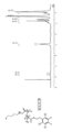
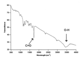
- 1 is an optical photograph of a sample of Example 1. It is a graph which shows the 1H NMR analysis result corresponding to the polymer structure of Example 2 sample. It is a graph which shows the 1H NMR analysis result corresponding to the polymer structure of Example 3 sample. 4 is an optical photograph of a sample. It is a graph which shows the 1H NMR analysis result corresponding to the polymer structure of Example 6 sample. It is a graph which shows the IR spectrum measurement result of Example 6 sample. It is a graph which shows the GPC measurement result of Example 11 sample.
- FIG. 12 is an optical photograph of a sample of Example 12.
- FIG. 4 is a schematic diagram of a disk test piece, in which (a) is a plan view and (b) is a cross-sectional view taken along the line D-D 'in (a). It is an optical photograph of a disk test piece. It is a coating process explanatory drawing, and the schematic diagram of the adhesion part of a coating film.
- FIG. 2 is a schematic diagram of a test piece of Example 1, where (a) is a plan view and (b) is a cross-sectional view taken along line E-E ′ of (a).
- Example 7 SEM image photographs of the surface of a test piece, before surface coating (a) and after surface coating (b).
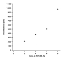
- Example 7 (dip) It is an XPS spectrum of the surface of a test piece. It is a graph which shows the relationship between the sample density
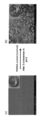
- Comparative Example 1 is a SEM image of a part of a test piece (Uncoated) before immersion in an acidic aqueous solution (pH 5) (a) and after immersion for 12 hours (b)
- Comparative Example 2 SEM image of a part of a test piece (PMMA-coated), before immersion in an acidic aqueous solution (pH 5) (a) and after immersion for 12 hours (b).
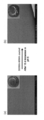
- Example 7 (spin) SEM image of a part of a test piece (DOMA-MMA coated), before immersion in an acidic aqueous solution (pH 5) (a) and after immersion for 12 hours (b). It is a graph showing the relationship between the immersion time and H 2 generation amount of Example 7 (spin -) test piece (DOMA-MMA) and Comparative Example 2 Test pieces (PMMA). Comparative Example 2 is a digital photograph of the whole test piece (PMMA), before immersion in an acidic aqueous solution (pH 5) (a) and after immersion for 10 hours (b).
- Example 7 (spin) A digital photograph of the entire test piece (DOMA-MMA), before immersion in an acidic aqueous solution (pH 5) (a) and after immersion for 24 hours (b).
- Comparative Example 1 A SEM image of a part of a test piece (Uncoated), after being immersed in a 3.5 wt% NaCl solution for 3 days. It is a SEM image of a part of comparative example 2 test piece (PMMA), Comprising: It is after being immersed in a 3.5 wt% NaCl solution for 3 days.
- Example 7 SEM image of a portion of a specimen (DOMA-MMA), after immersion in a 3.5 wt% NaCl solution for 3 days.
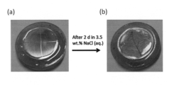
- 2 is a digital photograph of the entire test piece (PMMA) before immersion in a 3.5 wt% NaCl solution (a) and after immersion for 2 days (b).
- Example 7 A digital photograph of the entire test piece (DOMA-MMA), before immersion in a 3.5 wt% NaCl solution (a) and after immersion for 2 days (b). It is an outline explanatory view of an electrochemical test. Comparative Example 1 Specimen (Uncoated), Example 7 (spin) Specimen (DOMA-MMA), Example 11 (spin) Specimen (DOMA-HMA), Example 12 (spin) Specimen (DOMA-DMA)
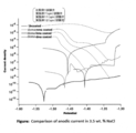
- FIG. 6 is a graph showing the results of the electrochemical test, and is a VI (cathodic current) characteristic in a 3.5 wt% NaCl solution.
- FIG. 6 is a graph showing the results of the electrochemical test, and is a VI (anodic current) characteristic in a 3.5 wt% NaCl solution. It is the photograph before and after the corrosion test of each main metal disc test piece without polymer coating (Uncoated) and with polymer coating (Polymer coated).
- the nano-coating material of the present invention is a nano-coating material that binds to the surface of a substrate made of a metal or an alloy, (A) a first side chain or terminal having a bonding group comprising a benzene ring having at least one pair of adjacent hydroxyl groups, and (B) It consists of a compound having a functional second side chain.
- the nanocoating material of the present invention has (A) a first side chain or terminal having a bonding group containing a benzene ring having at least one pair of adjacent hydroxyl groups in the polymer main chain, Since the bonding group of the first side chain capable of coordination bonding is firmly bonded to the metal surface, it has excellent adhesion to metals and alloys.
- hydrophobic second side chain when the (B) functional second side chain branched from the polymer main chain is hydrophobic (hereinafter sometimes referred to as “hydrophobic second side chain”). It can be used as a nano-coating material having excellent rust prevention properties.
- the development of conventional anti-corrosion coating materials focused on improving adhesion and creating a smooth oxide film on the metal surface. It has not been considered to combine with a hydrophobic material which is considered to lower the adhesiveness.
- the present inventor does not separate the structure of the anticorrosive coating material, and has a bonding group having a function of improving the adhesion to the substrate surface of a metal or alloy that requires anticorrosion, and oxygen or water. If it is made of a polymer having a hydrophobic group that can block the access and contact of reactants such as molecules and halide ions to the substrate surface, it will increase the adhesion and increase the rust prevention effect even if the film thickness is thin. I guessed it could be possible.
- Non-patent Document 2 Non-patent Document 2
- Mefps5 an adhesion protein of mussel
- the inventor noted that Mefps5 has dopamine.
- the inventor synthesized poly (dopamine methacrylamide-co-alkyl methacrylate) and dopamethacrylamide-styrene copolymer by combining a bonding group having a dopamine skeleton and a hydrophobic group.
- nano-coating material In the nanocoating material of the present invention, an embodiment in which the functional second side chain is hydrophobic will be described.
- the nano-coating material of this embodiment can be adhered as a nano-sized nano-coating film to the surface of a base material made of a metal or an alloy to prevent water molecules from approaching the base material surface.
- the nano-coating material of this embodiment has a polymer main chain, (A) a first side chain or terminal having a bonding group comprising a benzene ring having at least one pair of adjacent hydroxyl groups; (B) It has a hydrophobic second side chain.
- the “benzene ring having at least one pair of adjacent hydroxyl groups” refers to a benzene ring having two or more hydroxyl groups and at least any two of these hydroxyl groups being adjacent to each other.
- the “bonding group” means an organic constituent group that can be bonded to and bonded to a coating material by bonding to a substrate surface made of a metal or an alloy.
- the term “nano” in the present invention means a scale of 1 ⁇ m (micron meter) or less, that is, 1000 nm or less.
- the polymer main chain in the nanocoating material of the present invention can realize the objects and effects of the present invention, and may be various as long as it does not hinder this.
- carbon (C) -carbon (C) A chain bond structure may be used.
- a hetero atom such as oxygen or nitrogen may be interposed, or a carbon (C) ring or What intervened the heterocyclic ring etc. may be sufficient.
- More preferable examples are carbon (C) -carbon (C) chain bonds.
- (A) the bonding group of the first side chain may be various as described above as long as it has a benzene ring having at least one pair of adjacent hydroxyl groups.
- the benzene ring may be a single ring, or may constitute a polycycle or a heterocycle.
- the bond between the first side chain having a benzene ring and the polymer main chain may be in various forms such as a carbon (C) chain, a hetero atom or the like interposed therebetween.
- the hydrophobic second side chain may also be various. Any material that constitutes a hydrophobic organic group may be used.
- the following chemical formula (2) is a chemical formula that represents an example of a nano-coating material that is an embodiment of the present invention.
- the nanocoating material according to the embodiment of the present invention includes a polymer main chain P part, a first side chain R 1 having a bonding group, and a hydrophobic second side chain. R 2 .
- Examples of the polymer main chain P part include a polymer chain composed of a single bond of carbon (C), that is, a polymer main chain having an alkyl chain.
- C a single bond of carbon
- an alkyl chain By using an alkyl chain, it can be uniformly dispersed in an organic solvent with high dispersibility, and a smooth film having no defects can be easily formed by a wet coating method such as a spin coating method even if the film thickness is thin.
- an alkyl chain composed of a copolymer of acrylamide and acrylate can be mentioned as a preferable example.
- Symbols R 3 and R 4 in the polymer main chain P part represent a hydrogen atom or an organic group.
- R 3 and R 4 are each a hydroxyl group or a linear or branched alkyl group having 1 to 12 carbon atoms (C) and may be the same or different.
- C carbon atoms
- the ratio m: n of the main chain portion having the first side chain R 1 and the main chain portion having the second side chain R 2 is preferably 1: 6 or more and 1: 100 or less. Thereby, it can superpose
- the following chemical formula (3) is a chemical formula showing a preferred example of the side chain R 1 .
- the side chain R 1 shown in the chemical formula (3) has a bonding group Z.
- the bonding group Z is an organic group that can be coordinated to a metal atom on the surface of a substrate made of a metal or an alloy.
- the bonding group Z has a benzene ring having at least one pair of adjacent hydroxyl groups.
- a catechol group represented by the following chemical formula (4).
- the oxygen of the adjacent hydroxyl groups is coordinated with the metal atoms constituting the metal substrate (chelate bond), and the coating film Can be firmly bonded to the surface of the metal substrate.
- the bonding group Z may have a structure in which the benzene ring has three or more hydroxyl groups. With this configuration, the number of coordinate bonds with metal atoms per functional group is increased, and the adhesive force can be improved.
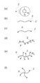
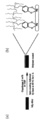
- FIG. 1 is an explanatory diagram outlining the chemical structure of a nano-coating material that is an embodiment of the present invention.
- the bonding group Z is indicated by a circle, and a catechol group is used as an example of Z.
- a catechol group is used as an example of Z.
- an example of the chemical structure regarding the arrangement of the bonding group Z of the nanocoating material is shown.
- B) is a material in which the bonding group Z is connected to one end side of the linear polymer main chain P part, and (c) is a bonding group Z to both ends of the linear polymer main chain P part.
- (D) is a material in which the bonding group Z is connected to the short first side chain of the linear polymer main chain P part, and (e) is a linear polymer main chain P.
- (F) shows a material in which the bonding group Z is connected to the terminal side of the cross-shaped polymer main chain P. Show. When the P parts are entangled with each other, the film stability is increased.
- the first side chain R 1 may have a plurality of bonding groups Z. Thereby, the number of the adhesion parts per one side chain can be increased, and adhesive force can be improved.
- the second side chain R 2 is hydrophobic.
- the metal surface can be covered with a polymer film having the second side chain R 2 , for example, water molecules approach the surface of the metal substrate. It is possible to prevent the metal atoms from reacting with water molecules and forming rust.
- the following chemical formula (5) shows an example of the second side chain R 2 and has a hydrophobic group R 5 .
- Preferred examples of the hydrophobic group R 5 of the chemical formula (5) include an alkyl group having 1 to 20 carbons (C).
- the number of carbon (C) is 0, that is, when the functional group R 5 is not provided, even if a coating film is formed, a waterproof effect cannot be obtained and rust is formed.
- the alkyl chain becomes too long, and it becomes difficult to solubilize in an organic solvent necessary for film formation.
- hydrophobic group R 5 examples include a methyl group, an ethyl group, an n-propyl group, an iso-propyl group, an n-butyl group, a sec-butyl group, an iso-butyl group, a tert-butyl group, Examples thereof include a pentyl group, n-hexyl group, n-heptyl group, n-octyl group, n-nonyl group, n-decyl group, n-undecyl group, n-dodecyl group and the like.
- the chemical formula (6) shows another example of the second side chain R 2 and is composed of a hydrophobic functional group.
- the second side chain R 2 is a phenyl group which is a hydrophobic functional group.
- benzene of the phenyl group benzene having a further substituent may be used.
- methylbenzene or anisole (methoxybenzene) may be used.
- PAH polycyclic aromatic hydrocarbon
- acene polycyclic aromatic such as naphthalene, anthracene and pentacene. It may be a functional group having a group hydrocarbon.
- the nanocoating material of this embodiment includes (A) a first side chain or terminal having a bonding group including a benzene ring having at least one pair of adjacent hydroxyl groups in the polymer main chain, and (B )
- a compound comprising a compound having a hydrophobic second side chain and having excellent adhesion to a substrate the following compounds can be preferably exemplified.
- P (DOMA-HMA) has a catechol group in the first side chain, a bonding group capable of coordinate bonding to a metal atom can firmly adhere the coating film to the metal surface.
- the hydrophobic group can be used as a nano-coating material having anti-rust properties. can do.
- the nanocoating material of the present invention can be applied to various applications because, for example, an ionic group that assists ion transport, an ethylene glycol group, or the like can be freely introduced.
- the nanocoating material of the present invention can impart necessary solubility according to various applications by, for example, controlling the catechol group counterpart. (Manufacturing method of nano coating material) Next, an embodiment of the method for producing a nanocoating material of the present invention will be described.
- a step of polymerizing a first monomer having a bonding group containing a benzene ring having at least one pair of adjacent hydroxyl groups and a second monomer having a hydrophobic functional group is performed.
- a hydrophobic second side chain R 2 and an organic group R 4 are bonded to one end of the C ⁇ C carbon double bond and the C ⁇ C carbon double bond.
- Examples of the first monomer in this case include dopamine-methacrylamide (N- (3,4-dihydroxyphenethyl) methacrylamide).
- Dopamine has a linking group having a benzene ring with at least one set of adjacent hydroxyl substituents.
- a hydroxyl group or a linear or branched alkyl group having 1 to 12 carbon atoms (C) may be used.
- Examples of the second monomer include methyl methacrylate or styrene.
- the hydrophobic second side chain R 2 is a methyl-ester group or a phenyl group.
- a hydroxyl group or a linear or branched alkyl group having 1 to 12 carbon atoms may be used.
- water repellent efficiency can be achieved.
- the following chemical reaction formula (7) shows an example of the polymerization reaction.
- the above polymerization reaction is performed by a heating reaction using, for example, AIBN (2,2′-Azobisisobutyronitrile) as a polymerization initiator. Thereby, it can superpose
- AIBN 2,2′-Azobisisobutyronitrile
- methacrylamide can be used as the first raw material monomer
- methacrylate can be used as the second raw material monomer to carry out a heat polymerization reaction.
- the polymerization reaction can be completed by heating at 70 to 80 ° C. for 30 to 50 hours using DMF as a solvent and 1-2 mol% of AIBN as a polymerization initiator.
- Chemical reaction formula (8) shows an example of a polymerization reaction when methacrylamide and methacrylate are used.
- FIG. 2A is a plan view showing an embodiment of the functional material of the present invention
- FIG. 2B is a cross-sectional view taken along line AA ′ in FIG.
- a disk-shaped base material 12 is used in this example.
- a nano-coating film 11 is formed so as to cover the entire surface of the substrate 12 with a uniform film thickness.
- the nano coating film 11 is formed of the nano coating material of the present invention.
- the film thickness of the nanocoating film 11 is preferably 100 nm or more and 1 ⁇ m or less.
- the film thickness is 100 nm or less, it is difficult to sufficiently prevent water molecules from approaching the surface of the substrate 12, and it is difficult to obtain a sufficient rust prevention effect.
- it exceeds 1 ⁇ m the burden of the material cost increases although the rust prevention effect does not change much.
- membrane 11 is a film
- the approach of a water molecule to the surface of the base material which consists of a metal or an alloy can be prevented, and a rust prevention effect can be improved.
- FIG. 3 is an enlarged schematic view of part B of FIG. 2B, wherein the nanocoating material shown in the chemical formulas (2) and (4) is used as the nanocoating film 11 and the metal / metal alloy substrate 12 is used. It is the figure which showed an example of the adhesion principle of the nano coating film at the time of using Mg metal or Mg alloy.
- the nanocoating film 11 is firmly bonded to the metal / metal alloy substrate 12 with the first side chain R 1 . Specifically, firmly adhered to the substrate 12 by a first side chain R 1 of the bonding group Z.
- the bonding group Z is a catechol group
- adjacent hydroxyl groups of the catechol group that is, two adjacent hydroxyl groups bonded to the benzene ring are coordinated to the Mg metal atom of the metal / metal alloy substrate 12. Adhere firmly.
- benzene stacks of catechol groups are ⁇ -stacked to stabilize the film and form a strong film.
- the hydrophobic second side chain R 2 prevents entry of water molecules and the like from the outside, and prevents contact between the surface of the metal / metal alloy substrate 12 and the water molecules and the like. Thus, the generation of rust on the surface of the metal / metal alloy substrate 12 is prevented.
- FIG. 4 is also a diagram showing an example of an adhesion principle of a nanocoating film (Polymer coating) when a metal / metal alloy substrate (Mg metal or Mg alloy) is used.
- a plurality of side chains are joined from a polymer backbone, which is a polymer main chain, and in some side chains (first side chains), oxygen adjacent to the benzene ring functions as a joining group (Surface binding group). Coordinates to the metal surface and bonds the film to the metal.
- the amide bond oxygen that connects this bonding group to the main chain forms a hydrogen bond network with another amide bond hydrogen to form a stable film.
- Another side chain (second side chain) joined to the polymer main chain is hydrophobic and functions as an anti-corrosion polymer side-chain.
- the method for producing a functional material of the present invention includes a nanocoating material dispersion preparation step F1 and a film formation step F2.
- Nano-coating material dispersion preparation process F1 In this step, the nanocoating material is dispersed in an organic solvent to prepare a nanocoating material dispersion.
- Various additives may be added to the dispersion as necessary. Such additives are, for example, a viscosity modifier, a photodegradation inhibitor, an antioxidant, a colorant, and the like, and can be selected in consideration of the usage environment, purpose of use, etc. of the rust-proof nanocoating film. .
- nanocoating material it is preferable to add the nanocoating material to the organic solvent and then stir well to disperse it uniformly.
- organic solvent examples include DMF and DMSO.
- the nano-coating material dispersion is applied to the surface of the substrate by, for example, a wet application method, and then dried to form a nano-coating film.
- the nanocoating film can be formed as a smooth film.
- Examples of the wet coating method include a spin coating method, a dipping method, and a casting method. Drying may be natural drying which is allowed to stand at room temperature, or may be drying by heating in an oven.
- the nanocoating material has excellent adhesion to metals or alloys, and can freely introduce ionic groups, ethylene glycol groups, and the like that assist ion transport. Therefore, it can be applied to various uses. Therefore, the functional material can be given not only rust prevention but also various functions depending on the application.
- the functional second side chain is hydrophobic in the nanocoating material of the present invention.
- the functional second side chain is hydrophilic (hereinafter referred to as “hydrophilic first side chain”).
- the nanocoating material of the present invention also includes a form that may be described as “two side chains”. In the following, the form in which the second side chain is hydrophilic will be described, but a part of the description common to the embodiment in which the second side chain is hydrophobic will be omitted.
- the nanocoating material of another embodiment has a polymer main chain, (A) a first side chain or terminal having a bonding group comprising a benzene ring having at least one pair of adjacent hydroxyl groups; (B) It has a hydrophilic second side chain.
- hydrophilic group of the second side chain examples include ethylene glycol, alkylamine, and alkylammonium.
- the polymer main chain has (A) a first side chain or terminal having a bonding group containing a benzene ring having at least one pair of adjacent hydroxyl groups, and is coordinated to a metal atom. Since possible bonding groups are firmly bonded to the metal surface, they have excellent adhesion to metals and alloys.
- it since it has a hydrophilic second side chain, it can be used for, for example, a binder of a lithium ion battery electrode.
- the nanocoating material has (A) a first side chain or terminal having a bonding group containing a benzene ring having at least one pair of adjacent hydroxyl groups, and (B) a hydrophilic main chain in the polymer main chain.
- a compound having a second side chain the following compounds can be preferably exemplified as examples of those having excellent adhesion to a substrate.
- P (DOMA-DMAEMA) is cationic and P (DOMA-PEGMA) is neutral.
- These nanocoating materials can be used as a material for a coating agent for suppressing lithium ions from becoming needles.
- P (DOMA-DMAEMA) does not dissolve in ethylene carbonate, and therefore can be used as a binder for lithium ion battery electrodes.
- P (DOMA-PEGMA) is expected to be used as a binder for lithium ion battery electrodes, for example.
- the first monomer having a bonding group including a benzene ring having at least one pair of adjacent hydroxyl groups and the second monomer having a hydrophilic functional group are polymerized.
- the process to make it include.
- Examples of the second monomer having a hydrophilic functional group include ethylene glycol, alkylamine, and alkylammonium.
- the nanocoating material of the present invention comprises a polymer main chain P part, a first side chain R 1 having a bonding group Z composed of a benzene ring having at least one pair of adjacent hydroxyl groups, and a functional second side chain. Since the structure has R 2 , the bonding group Z of the first side chain R 1 that is dispersed in an organic solvent, can be easily and uniformly applied by a wet coating method, and can be coordinated to a metal atom is a metal surface. The coating film can be firmly adhered to the surface. Further, when the second side chain R 2 is hydrophobic, the hydrophobic second side chain R 2 can prevent water molecules and the like from approaching the surface of the base material made of metal or alloy. Therefore, it is possible to provide a nano-coating material that can form a coating film having a high antirust effect even when the film thickness is thin.
- the nanocoating material of the present invention has a structure in which the polymer main chain P part is a polymer chain composed of a single bond of carbon (C). It is possible to provide a nano-coating material that can be applied smoothly and can form a nano-coating film having a high antirust effect.
- the nanocoating material of the present invention has a structure in which the polymer main chain P part is composed of a copolymer of acrylamide and acrylate, so that it can be dispersed uniformly in an organic solvent and applied easily and smoothly by a wet coating method, and the film thickness is thin.
- the nanocoating material capable of forming a nanocoating film having excellent adhesion to metals and alloys.
- the bonding group Z is a catechol group
- the bonding group of the first side chain R 1 capable of coordinating bonding to a metal atom strongly bonds the coating film to the metal surface.
- a nano-coating material capable of forming a coating film having excellent adhesion to a metal or an alloy even when the film thickness is thin can be provided.
- the functional (hydrophobic) second side chain R 2 has a structure in which an alkyl group having 1 to 12 carbons (C) is present. It is possible to R 2 to prevent the access of such water molecules to the surface of a substrate made of a metal or alloy, even thin film thickness, film can be formed excellent coating film adhesion to metals and alloys Nano-coating material can be provided.
- the functional (hydrophobic) second side chain R 2 is a functional group containing a benzene ring, so that water molecules or the like on the surface of a substrate made of a metal or an alloy can be used. Since the approach can be prevented, a rust preventive coating material capable of forming a coating film having a high rust preventive effect even when the film thickness is thin can be provided.
- the method for producing a nanocoating material of the present invention comprises a first monomer having a bonding group having a benzene ring having at least one pair of adjacent hydroxyl substituents, and a second monomer having a hydrophobic group or a hydrophilic group.
- a structure comprising a step of preparing a monomer dispersion solution by dispersing in an organic solvent and a step of polymerizing the monomers in the monomer dispersion solution, so that the bonding is composed of a polymer main chain and a benzene ring having at least one pair of adjacent hydroxyl groups.
- a nanocoating material having a first side chain having a group and a hydrophobic second side chain can be easily produced with high yield.
- the first monomer has an acrylamide group
- the acrylamide group has a hydroxyl group or an alkyl group having 1 to 12 carbon atoms (C).
- the nanocoating material can be easily produced with high yield.
- the method for producing a nano-coating material according to an embodiment of the present invention is high.
- a nanocoating material having a molecular main chain can be easily produced with high yield.
- the functional group of the functional (hydrophobic) second side chain is an alkyl group having 1 to 12 carbons (C), or Since the structure is a functional group containing a benzene ring, a nanocoating material having a polymer main chain and a hydrophobic side chain can be easily produced with high yield.
- the method for producing a nano-coating material of the present invention uses AIBN as a polymerization initiator and is polymerized by a heating reaction, so that a coating material having a polymer main chain can be easily produced with high yield.
- a nano-coating film made of a nano-coating material is formed on the surface of a substrate made of a metal or an alloy, and the first side chain or terminal bonding group of the nano-coating material is formed on the surface of the metal. Coordinates to metal atoms and can be firmly bonded.
- the functional second side chain is hydrophobic, it prevents water molecules from approaching the surface of the base material made of a metal or an alloy of a hydrophobic group, and has a high rust prevention effect. Can be protected.
- the functional material of the present invention since the nanocoating material of the present invention has excellent adhesion to a metal or an alloy, for example, the functional material of the present invention includes a lithium battery ion battery electrode as a substrate, and the nanocoating material as a binder. Combined forms are also included.
- the nano coating film of the functional material of the present invention has a thickness of 100 nm or more and less than 1 ⁇ m, it has excellent adhesion to the substrate surface even if the film thickness is thin.
- the method for producing a functional material according to the present invention includes a step of dispersing the nanocoating material described above in an organic solvent to prepare a nanocoating material dispersion, and the nanocoating material dispersion by a wet coating method. And then drying to form a nano-coating film. Therefore, the bonding group capable of coordinate bonding to the metal atom can firmly adhere the coating film to the metal surface.
- Example 1 (Material preparation / characteristic evaluation) As shown in the following chemical reaction formula (9), the charging ratio (x: y) of the material (DOMA1) as the first raw material monomer and the material (methyl methacrylate) as the second raw material monomer is ( 1: 2.5) and then mixed in DMF together with AIBN, which is a radical initiator, to prepare a monomer dispersion solution. Then, the monomer dispersion solution was stirred at 75 ° C. for 40 hours while stirring. , Free radical polymerization reaction (Free radical polymerization). The AIBN concentration in DMF was 1.5 mol%.
- FIG. 5 is an optical photograph of the sample of Example 1 (denoted as DOMA-C 1 ).
- Example 2 An Example 2 sample was prepared in the same manner as the Example 1 sample except that the charge ratio was 1: 5.
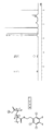
- FIG. 6 is a graph showing the results of 1H NMR analysis of the sample of Example 2.
- the molecular structure indicating the position of 1H corresponding to the NMR peak is also shown.
- m: n 1: 7.
- Example 3 sample was prepared in the same manner as Example 1 except that the charging ratio (x: y) was 1:10.
- FIG. 7 is a graph showing the results of 1H NMR analysis of the sample of Example 3.
- the molecular structure indicating the position of 1H corresponding to the NMR peak is also shown.
- m: n 1: 14.
- Example 4 As shown in the following chemical reaction formula (10), the second raw material monomer was used as a material (hexyl methacrylate), and the charge ratio (x: y) was changed to 1: 1, as in the sample of Example 1. Thus, a sample of Example 4 was prepared.
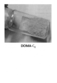
- FIG. 8 is an optical photograph of the sample of Example 4 (denoted as DOMA-C 6 ).
- the free radical polymerization reaction (Free radical polymerization) shown in the chemical reaction formula (10) was performed.
- Example 5 A sample of Example 5 was prepared in the same manner as the sample of Example 1 except that the second raw material monomer was the same material (hexyl methacrylate) as in Example 4 and the charge ratio (x: y) was 1: 2. did.
- Example 6 A sample of Example 6 is prepared in the same manner as the sample of Example 1 except that the second raw material monomer is the same material (hexyl methacrylate) as in Example 4 and the charging ratio (x: y) is 1: 4. did.
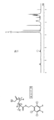
- FIG. 9 is a graph showing the results of 1H NMR analysis of the sample of Example 6.
- the molecular structure indicating the position of 1H corresponding to the NMR peak is also shown.
- m: n 1: 10.
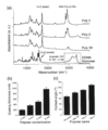
- FIG. 10 is a graph showing IR spectrum measurement results of the sample of Example 6. An O—H absorption peak and a C ⁇ O absorption peak were observed.
- Example 7 A sample of Example 7 was prepared in the same manner as the sample of Example 2 except that the free radical polymerization reaction time shown in the chemical reaction formula (9) was 24 hours.
- Example 8 An Example 8 sample was prepared in the same manner as the Example 3 sample except that the free radical polymerization reaction time shown in the chemical reaction formula (9) was 24 hours.
- Example 9 An Example 9 sample was prepared in the same manner as the Example 8 sample except that the charging ratio (x: y) was set to 1:30.
- Example 10 A sample of Example 10 was prepared in the same manner as the sample of Example 8 except that the charging ratio (x: y) was 1:90.
- Example 11 A sample of Example 11 was prepared in the same manner as the sample of Example 6 except that the free radical polymerization reaction time shown in the chemical reaction formula (10) was 24 hours.
- FIG. 11 is a graph showing the GPC measurement results of the sample of Example 11.
- Example 12 As shown in the following chemical reaction formula (11), the second raw material monomer is a material (dodecyl methacrylate), the free radical polymerization reaction time is 24 hours, and the charging ratio (x: y) is 1: 3. A sample of Example 12 was prepared in the same manner as the sample of Example 1 except that.
- FIG. 12 is an optical photograph of the sample of Example 12 (denoted as DOMA-C 12 ).
- Free radical polymerization reaction Free radical polymerization
- Example 13 As shown in the following chemical reaction formula (12), the second raw material monomer is a material (styrene), the free radical polymerization reaction time is 24 hours, and the charging ratio (x: y) is 1: 7.
- Example 13 sample was prepared in the same manner as Example 1 sample.
- Free radical polymerization reaction Free radical polymerization
- Table 1 is a table showing synthesis conditions and synthesis results of Example Samples. Abbreviations, x, y raw material names, preparation ratio (raw material composition), analysis ratio (synthetic material composition), polymerization time, catechol group It is a table
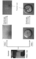
- an Mg alloy disk was placed on a disk-shaped resin, and then pressed so that the thickness direction was completely embedded, and then the surface was polished to prepare a disk specimen.
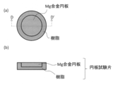
- FIG. 13 is a schematic diagram of a disk specimen, in which (a) is a plan view and (b) is a cross-sectional view taken along the line D-D 'in (a).
- FIG. 14 is an optical photograph of the disk specimen.
- Example 1 test piece (Production of Example 1 test piece) Next, the sample of Example 1 was dispersed in THF at a rate of 8 wt% to prepare a dispersion.
- dispersion 1 was spin-coated so as to cover the exposed Mg surface of the disk specimen.
- the spin coating conditions were (1000 rpm, 15 sec, followed by 2500 rpm, 30 sec).
- Example 1 The dispersion was heated and held under conditions of 60 ° C. for 1 hour and dried to prepare a test piece of Example 1.
- FIG. 15 is an explanatory diagram of a coating process and a conceptual diagram of an adhesion portion of a coating film.
- a Polymer 8 wt% THF solution was spin-coated on one side of a substrate made of Mg alloy, and then heated at 60 ° C. for 1 h to prepare a Polymer coated substrate.
- the oxygen atom of the polymer catechol group is coordinated and bonded to the Mg atom constituting the substrate. This indicates that the hydrophobic side chains of the polymer are closely packed, and water molecules and the like can be prevented from approaching the substrate surface.
- FIG. 16 is a schematic diagram of the test piece of Example 1, where (a) is a plan view and (b) is a cross-sectional view taken along line E-E 'of (a).
- Example 1 The test piece was formed so that the bottom and side surfaces of the Mg disk were completely covered with the resin, the exposed surface was covered with the coating film, and the coating film also covered a part of the resin. There is no exposed surface.
- the thickness of the coating film was 500 nm. Moreover, it was confirmed by SEM observation that the coating film was a smooth film in which pores having a pore diameter of 50 nm or more were not formed.
- Examples 2 to 13 Test pieces were prepared in the same manner as the Example 1 test piece except that the samples 2 to 13 were used.
- the disc specimen was used as a comparative example 1 specimen. This is a test piece for measuring conditions in which a coating film is not formed.
- Comparative Example 2 Preparation of Test Piece
- PMMA polymethyl methacrylate resin
- FIG. 17 is a graph showing the relationship between the hydrogen generation amount of hydrogen generated when each test piece is immersed in an acidic buffer aqueous solution (pH 5) and the immersion time.
- test piece of Example 2 The test piece of Example 2, the test piece of Example 3, the test piece of Example 5, and the test piece of Example 6 were significantly improved in rust prevention effect as compared with Comparative Examples 1 and 2.
- test piece of Example 5 only 5 mL / cm 2 of hydrogen was generated even in about 95 hours, and a remarkable rust prevention effect was observed.
- FIG. 18 is a SEM photograph of the surface without a coating film, immediately after polishing (a), after immersion in an acidic (pH 5) buffer for 10 hours (b), and after immersion in a 3.5 wt% NaCl aqueous solution for 1 day. (C).
- FIG. 19 is a SEM photograph of the substrate surface when a coating film (Example 5 test piece) was formed, immediately after film formation (a), after being immersed in an acidic (pH 5) buffer for 4 days (b), (C) After immersion in 3.5 wt% NaCl aqueous solution for 4 days. In the acidic solvent, rust was seen on the surface, but in the alkaline solvent, almost no rust was seen on the surface.
- Table 2 is a table showing the production conditions and rust prevention evaluation results of the test pieces of Example 1 to Example 6 and Comparative Examples 1 and 2.
- Example 7 (dip) test piece) (Production of disk specimen)
- an Mg alloy rod (commercial product, Mg—Al 3% —Zn 1% alloy, Mg alloy (AZ31), diameter 1.5 cm) was cut to produce a Mg alloy disc. The thickness was 4 mm.
- the surface was polished with SiC paper and cleaned in the order of EtOH, H 2 O, and acetone to prepare a disk specimen.
- Example 7 was dispersed in DMF at a rate of 2 mg / mL to prepare a dispersion.
- Example 7 (dip) specimen that was surface-coated in Example 7 was prepared. Produced.
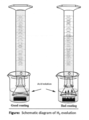
- FIG. 20 is an explanatory diagram of this dip-coating method.
- FIG. 21 is a SEM image photograph of the surface of the test piece of Example 7 (dip), which is before surface coating (a) and after surface coating (b).
- FIG. 22 is an XPS spectrum of the surface of Example 7 (dip) test piece.
- Polymer deposited AZ31 (b) is the XPS spectrum of the surface of the Example 7 (dip) test piece
- Bare AZ31 (a) is the XPS spectrum of the Comparative Example 1 test piece measured for comparison.
- Example 7 (spin) test piece (Production of disk specimen) After producing the disk test piece, film formation was performed by a spin coating method, and this was heat-dried at 60 ° C. to produce an Example 7 (spin) test piece.
- the film forming conditions are (1000 rpm, 15 sec, followed by 2500 rpm, 30 sec).
- Example 7 (spin) The polymer film of the sample of Example 7 of the test piece was transparent and stable in the air.
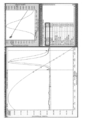
- a dispersion liquid having a different concentration of the sample of Example 7 was prepared, spin-coated under the same conditions, and then the film thickness was measured with a surface profiler (DEKTAK). The film thickness was found to depend on the concentration of the Example 7 sample in the dispersion.
- FIG. 23 is a graph showing the relationship between the sample concentration in the dispersion and the film thickness.
- Example 11 (spin) test piece was prepared in the same manner as the Example 7 (spin) test piece except that the sample of Example 11 was used.
- Example 12 (spin) test piece was prepared in the same manner as the Example 7 (spin) test piece except that the sample of Example 12 was used.
- Table 3 shows the production conditions for each test piece.
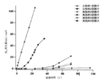
- FIG. 24 is an explanatory diagram of the measurement of H 2 generation amount.
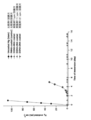
- FIG. 25 is a graph showing the relationship between the immersion time of a test piece immersed in an acidic aqueous solution (pH 5) and the amount of H 2 generated, and shows the dependency of the material.
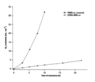
- Example 7 (spin), 11 (spin), and 12 (spin) test pieces produced less H 2 than the Comparative Examples 1 and 2 test pieces, and the metal surface protective effect was clearly improved.
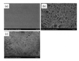
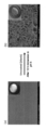
- FIG. 26 is an SEM image of a part of the test piece (Uncoated) of Comparative Example 1, which is before immersion (a) and after immersion for 12 hours (b) in an acidic aqueous solution (pH 5).
- the inset is a digital photograph of the entire specimen.
- fine cracks were generated on the entire surface by immersion in an acidic aqueous solution (pH 5) for 12 hours.
- FIG. 27 is a SEM image of a part of the test piece of Comparative Example 2 (PMMA-coated), which is before immersion in an acidic aqueous solution (pH 5) (a) and after immersion for 12 hours (b).
- the inset is a digital photograph of the entire specimen.
- a large crack was generated on the entire surface by immersion in an acidic aqueous solution (pH 5) for 3 days.
- FIG. 28 is a SEM image of a part of the test piece (DOMA-MMA coated) in Example 7 (DOMA-MMA coated) before immersion in an acidic aqueous solution (pH 5) (a) and after immersion for 12 hours (b).
- the inset is a digital photograph of the entire specimen.
- Example 7 (spin) test piece no change was observed on the surface even when immersed in an acidic aqueous solution (pH 5) for 15 days.
- FIG. 29 is a graph showing the relationship between the immersion time of Example 7 (spin) test piece (DOMA-MMA) and Comparative Example 2 test piece (PMMA) and the amount of generated H 2 .
- FIG. 30 is a digital photograph of the entire Comparative Example 2 test piece (PMMA), before being immersed in an acidic aqueous solution (pH 5) (a) and after being immersed for 10 hours (b).
- the entire surface was discolored by being immersed in an acidic aqueous solution (pH 5) for 10 hours.
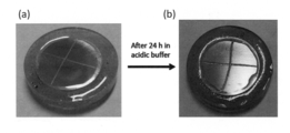
- FIG. 31 is a digital photograph of the whole Example 7 (spin) test piece (DOMA-MMA), which is before immersion in an acidic aqueous solution (pH 5) (a) and after immersion for 24 hours (b).
- Example 7 (spin) test piece even when immersed in an acidic aqueous solution (pH 5) for 24 hours, the surface hardly changed.
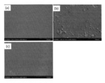
- FIG. 32 is an SEM image of a portion of Comparative Example 1 test piece (Uncoated), after being immersed in a 3.5 wt% NaCl solution for 3 days.
- the inset is a digital photograph of the entire specimen.
- fine cracks were generated on the entire surface when immersed in a 3.5 wt% NaCl solution for 3 days.
- FIG. 33 is an SEM image of a part of the comparative example 2 test piece (PMMA), which is after being immersed in a 3.5 wt% NaCl solution for 3 days.
- the inset is a digital photograph of the entire specimen. Fine cracks occurred on the entire surface.
- FIG. 34 is an SEM image of a part of the test piece (DOMA-MMA) of Example 7 (spin), after being immersed in a 3.5 wt% NaCl solution for 3 days.
- the inset is a digital photograph of the entire specimen. Little change was seen on the surface.
- Example 7 (spin) test piece and the Comparative Example 2 test piece was cross-cut and immersed in a 3.5 wt% NaCl solution for 2 days.
- FIG. 35 is a digital photograph of the entire test piece (PMMA) of Comparative Example 2 before being immersed in a 3.5 wt% NaCl solution (a) and after being immersed for 2 days (b).
- the surface hardly changed even when immersed in a 3.5 wt% NaCl solution for 2 days.
- FIG. 36 is a digital photograph of the entire Example 7 (spin) test piece (DOMA-MMA), before being immersed in a 3.5 wt% NaCl solution (a) and after being immersed for 2 days (b).
- the surface hardly changed.
- a sample piece electrode part was prepared by insulating other than the measurement surface.
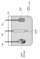
- FIG. 37 is an explanatory diagram of an electrochemical test.
- the sample piece electrode part has a reference electrode (Reference electrode: RE) and a counter electrode (Counter electrode: CE) in an electrolyte solution (NaCl 3.5 wt% solution) filled in the container. .)).
- RE reference electrode
- CE counter electrode
- Each electrode is connected to a potentio / galvanostat (not shown) through wiring.
- the sample piece electrode part is left for 10 minutes, set to a natural potential, and at a scanning speed of 1 mV / sec, by linear sweep voltammetry (Linear sweep voltammetry: LSV), Corrosion current was measured.
- LSV Linear sweep voltammetry
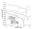
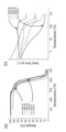
- FIG. 38 shows Comparative Example 1 specimen (Uncoated), Example 7 (spin) specimen (DOMA-MMA), Example 11 (spin) specimen (DOMA-HMA), Example 12 (spin) specimen ( 2 is a graph showing the results of an electrochemical test of DOMA-DMA), which is a VI (Cathic current) characteristic in a 3.5 wt% NaCl solution.
- Comparative Example 1 test piece Uncoated, it was considered that H 2 O was electrolyzed on the metal surface, electrons were taken into the electrode, and a large current flowed. On the other hand, in the coated test piece, it was assumed that the current did not flow so much and the electrolysis reaction of H 2 O was suppressed.
- FIG. 39 shows a comparative example 1 specimen (Uncoated), Example 7 (spin) specimen (DOMA-MMA), Example 11 (spin) specimen (DOMA-HMA), Example 12 (spin) specimen ( It is a graph which shows the electrochemical test result of DOMA-DMA), Comprising: It is VI (Anodic current) characteristic in a 3.5 wt% NaCl solution.
- Mg alloy rod commercial product, Mg—Al3% —Zn1% alloy, Mg alloy (AZ31), diameter 1.5 cm
- Mg alloy disk was cut to produce a Mg alloy disk.
- a pure Al rod (commercial product, Al- (99)%, diameter 1.5 cm) was cut to produce a pure Al disk.
- a pure Fe rod (commercial product, Fe- (99.9)%, diameter 1.5 cm) was cut to prepare a pure Fe disk. The thickness of each disk was 4 mm.
- the disc test piece having a metal exposed surface is polished after being pushed so that the thickness direction is completely embedded. (Mg alloy) was produced.
- Example 7 test piece Mg, Cu, Al, Fe
- a disk test piece Mg alloy
- film formation by spin coating 1000 rpm, 15 sec followed by 2500 rpm, 30 sec
- was performed. was heat-dried at 60 ° C. to prepare a test piece of Example 7 (Mg alloy). This is a sample prepared for examining the dependency on the metal material, and is the same as that of Example 7 (spin) test piece.
- Example 7 A test piece (Cu) was prepared in the same manner as in (Preparation of Example 7 (spin) test piece) except that a disk test piece (Cu) was used.
- Example 7 A test piece (Al) was prepared in the same manner as in (Preparation of Example 7 (spin) test piece) except that a disk test piece (Al) was used.
- Example 7 A test piece (Fe) was prepared in the same manner as in (Preparation of Example 7 (spin) test piece) except that a disk test piece (Fe) was used.
- test pieces were immersed in a 3.5 wt% NaCl solution for 1 to 7 days to conduct a corrosion test.
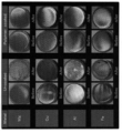
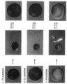
- FIG. 40 is a photograph of each alloy or metal disk test piece before and after a corrosion test (Before-After) with and without a polymer coating (Uncoated) and with a polymer coating (Polymer coated).
- Uncoated Before is a photograph immediately after the preparation of each alloy or metal disk specimen and before the corrosion test.
- Polymer coated Before is a photograph immediately after the preparation of a test piece coated with each alloy or metal, and before the corrosion test.
- Polymer coated After is an optical photograph after a corrosion test of a test piece coated with a polymer coating of each alloy or metal.
- Example 7 doma-mma coated test piece
- Example 11 doma-hma coated test piece
- Example 12 doma-dma coated test piece.
- the sample electrode part was prepared by insulating the surface other than the measurement surface.
- the sample piece electrode part was immersed together with a reference electrode (Reference electrode: RE) and a counter electrode (Counter electrode: CE) in an electrolytic solution (NaCl 3.5 wt% solution) filled in the container.
- RE reference electrode
- CE counter electrode
- electrolytic solution NaCl 3.5 wt% solution
- the sample piece electrode part is left for 10 minutes, set to a natural potential, and at a scanning speed of 1 mV / sec, by linear sweep voltammetry (Linear sweep voltammetry: LSV), Corrosion current was measured.
- LSV Linear sweep voltammetry
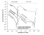
- FIG. 41 is a graph showing the electrochemical test results of Uncoated, Example 7 doma-mma coated test piece, Example 11 doma-hma coated test piece, and Example 12 doma-dma coated test piece, in a 3.5 wt% NaCl solution.
- the V-I (Cathic current) characteristic is shown (dotted line in FIG. 41).
- Table 4 is a table showing the difference in characteristics depending on the alloy or metal.
- E corr is (corrosion potential)
- i corr is (corrosion current).
- Example 14 sample was prepared in the same manner as Example 5 sample except that the free radical polymerization reaction temperature shown in chemical reaction formula (10) was 24 hours.
- FIG. 42 shows the 1H NMR analysis result of the sample of Example 14.
- Example 14 m n of the sample was 1: 6. The yield of the polymerization reaction was 61%.
- Example 14 the dispersion of the sample of Example 14 was spin-coated on a quartz substrate in the same manner as in the above-described Example 1 test piece preparation, and the UV-V spectrum was measured.
- FIG. 43 shows the measured spectrum in this case. No peak was observed in the wavelength range of 400 to 700 nm, confirming that the coating film had transparency.
- Example 14 The coating process was performed on each of the glass substrate and the Mg substrate in the same manner as described above.
- FIG. 44 shows the result of the Scotch tape test of the sample of Example 14 coated with a small amount of rhodamine B dye.
- the characters “NIMS” and “N” are provided in advance. As a test result, it was confirmed that peeling of the coating film did not occur in 20 scotch tape tests, immersion in distilled water for 24 hours, and 20 scotch tape tests.
- FIG. 46 shows the results of the scotch tape test in the case where the different substrates (Fe, Cu, Al) of the sample of Example 14 were coated. In any case, it can be seen that the coating film did not peel even after 20 scotch tape tests.
- Example 14 Contact angle test A coating film of Example 14 was formed on a glass substrate, immersed in a different pH aqueous solution, washed with distilled water, and measured for a static water contact angle when dried under an N 2 gas float.
- pH 1 and pH 3 were adjusted with 1M HCl, pH 9 with Tris buffer, and pH 11 with 1M NaOH.
- Example 15 (Material adjustment and physical property evaluation) The results are shown in Table 5, assuming that the time of the free radical polymerization reaction shown in the chemical reaction formulas (9), (10) and (11) is 24 hours and the amount of AlBN used is 1 mol%. A polymerization reaction was performed.
- Example 15 Six types of polymers were obtained as samples. In Table 5, poly2 represents the sample of Example 14.
- Table 6 shows average molecular weight, DOMA unit mass%, and Tg (° C.).
- FIG. 48 shows (a) a TGA curve and (b) a DSC thermogram (second heating cycle) for each of these samples.
- FIG. 49 shows (a) a comparison of FT-IR spectra, (b) the relationship between the polymer concentration measured by the surface profiler and the thickness of the coating film, and (c) the static water contact angle.
- ⁇ Example 16> (1) Synthesis of P (DOMA-DMAEMA) N- (3,4-dihydroxyphenethyl) methacrylamide (DOMA) and 2- (Dimethylamino) ethyl methacrylate (DMAEMA) were synthesized by free radical polymerization using azoisobutyronitrile (AIBN).
- AIBN azoisobutyronitrile
- DOMA monomer (444 mg, 2 mM) and AIBN (3 mol%) were added and purged with argon gas for 30 minutes three times.
- 15 ml of dehydrated dimethylformamide (DMF) was added to the flask and stirred with a stir bar.
- DMAEMA (1.57 g, 10 mM) was added by a syringe.
- the flask was placed in a 75 ° C. oil bath and stirred for 18 hours. Thereafter, the reaction solution was cooled to room temperature, and DMF was removed under reduced pressure.
Abstract
Description
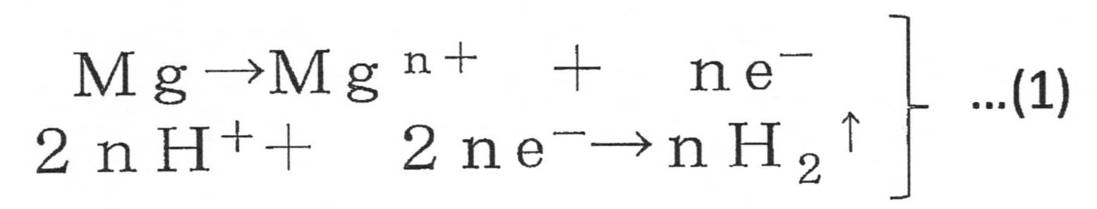
(1)金属または合金からなる基材の表面に結合するナノコーティング材料であって、
高分子主鎖に、
(A)少なくとも一組の隣接水酸基を持つベンゼン環を含む接合基を有する第1の側鎖または末端、および、
(B)官能性の第2の側鎖
を有する化合物からなる。
(2)前記第2の側鎖が、疎水性である。
(3)前記第2の側鎖が、親水性である。
(4)前記高分子主鎖が炭素(C)一重結合からなる高分子鎖である。
(5)前記高分子主鎖がメタクリルアミドとメタクリレートのコポリマーからなる。
(6)前記第1の側鎖の前記接合基がカテコール基を含む。
(7)前記第2の側鎖が、炭素(C)数が1以上12以下のアルキル基を有する。
(8)前記第2の側鎖が、ベンゼン環を含む官能基を有する。 The nanocoating material of the present invention is characterized by the following.
(1) A nano-coating material that binds to the surface of a substrate made of a metal or alloy,
In the polymer main chain,
(A) a first side chain or terminal having a bonding group comprising a benzene ring having at least one pair of adjacent hydroxyl groups, and
(B) It consists of a compound having a functional second side chain.
(2) The second side chain is hydrophobic.
(3) The second side chain is hydrophilic.
(4) The polymer main chain is a polymer chain comprising a carbon (C) single bond.
(5) The polymer main chain is made of a copolymer of methacrylamide and methacrylate.
(6) The bonding group of the first side chain includes a catechol group.
(7) The second side chain has an alkyl group having 1 to 12 carbons (C).
(8) The second side chain has a functional group containing a benzene ring.
(9)金属または合金の表面と結合するナノコーティング材料の製造方法であって、
少なくとも一組の隣接水酸基を持つベンゼン環を含む接合基を有する第1のモノマーと、疎水性基または親水性基を有する第2のモノマーを重合させる重合工程
を含む。
(10)前記第1のモノマーは、メタクリルアミド基を有する。
(11)前記第2のモノマーは、メタクリレート基を有する。
(12)前記メタクリルアミド基が、水酸基または炭素(C)数が1以上12以下のアルキル基を有する。
(13)前記アクリレート基が水酸基又は炭素(C)数が1以上12以下のアルキル基を有する。
(14)前記疎水性基が、炭素(C)数が1以上12以下のアルキル基、または、ベンゼン環を含む。
(15)前記重合工程では、重合開始剤としてAIBNを用い、加熱反応により、前記第1のモノマーと前記第2のモノマーとを重合させる。
(16)本発明のコーティング剤は、金属または合金からなる基材のコーティング剤であって、前記ナノコーティング材料を含むことを特徴としている。 The method for producing a nanocoating material of the present invention is characterized by the following.
(9) A method for producing a nanocoating material that binds to the surface of a metal or alloy,
A polymerization step of polymerizing a first monomer having a bonding group including a benzene ring having at least one pair of adjacent hydroxyl groups and a second monomer having a hydrophobic group or a hydrophilic group;
(10) The first monomer has a methacrylamide group.
(11) The second monomer has a methacrylate group.
(12) The methacrylamide group has a hydroxyl group or an alkyl group having 1 to 12 carbon atoms (C).
(13) The acrylate group has a hydroxyl group or an alkyl group having 1 to 12 carbon atoms.
(14) The hydrophobic group includes an alkyl group having 1 to 12 carbon atoms (C) or a benzene ring.
(15) In the polymerization step, AIBN is used as a polymerization initiator, and the first monomer and the second monomer are polymerized by a heating reaction.
(16) The coating agent of the present invention is a base material coating agent made of a metal or an alloy, and is characterized by containing the nano-coating material.
(17)金属または合金からなる基材の表面に、前記ナノコーティング材料が結合している。
(18)前記基材の表面には、前記ナノコーティング材料によるナノコーティング膜が形成されており、前記ナノコーティング膜の膜厚が100nm以上1μm未満である。
(19)前記基材が、リチウムイオン電池電極である。 The functional material of the present invention is characterized by the following.
(17) The nano-coating material is bonded to the surface of a substrate made of a metal or alloy.
(18) A nanocoating film made of the nanocoating material is formed on the surface of the base material, and the film thickness of the nanocoating film is 100 nm or more and less than 1 μm.
(19) The base material is a lithium ion battery electrode.
(20)本発明の機能性材料の製造方法は、前記ナノコーティング材料を有機溶媒に分散し、ナノコーティング材料分散液を調製する工程、および
前記ナノコーティング材料分散液を、湿式塗布法により基材表面に塗布した後、乾燥させて、基材表面にナノコーティング材を結合させる工程
を含むことを特徴としている。 The method for producing the functional material of the present invention includes:
(20) The method for producing a functional material of the present invention includes a step of dispersing the nano-coating material in an organic solvent to prepare a nano-coating material dispersion, and the nano-coating material dispersion by a wet coating method. It is characterized by including a step of applying a nanocoating material to the surface of a base material after drying on the surface.
(A)少なくとも一組の隣接水酸基を持つベンゼン環を含む接合基を有する第1の側鎖または末端、および、
(B)官能性の第2の側鎖
を有する化合物からなる。 The nano-coating material of the present invention is a nano-coating material that binds to the surface of a substrate made of a metal or an alloy,
(A) a first side chain or terminal having a bonding group comprising a benzene ring having at least one pair of adjacent hydroxyl groups, and
(B) It consists of a compound having a functional second side chain.
(ナノコーティング材料)
本発明のナノコーティング材料において、官能性の第2の側鎖が疎水性である実施形態について説明する。 Based on such inferences, the present inventor has made extensive studies. In the course of this study, the present inventor recently contacted a report (Non-patent Document 2) that Mefps5, an adhesion protein of mussel, adheres firmly to various substrates including Au metal. In reviewing this report, the inventor noted that Mefps5 has dopamine. The inventor synthesized poly (dopamine methacrylamide-co-alkyl methacrylate) and dopamethacrylamide-styrene copolymer by combining a bonding group having a dopamine skeleton and a hydrophobic group. Therefore, when a rust-proof nano-coating film using these polymers as a nano-coating material is formed on the surface of the Mg alloy substrate, it can be easily applied to the Mg alloy substrate and is firmly bonded. It was found that even when the film thickness was small, the approach / contact of the corrosive reactant to the substrate surface could be prevented, and a remarkable rust prevention effect was obtained. Based on such knowledge, the present inventor completed a new nano-coating material by further studying.
(Nano-coating material)
In the nanocoating material of the present invention, an embodiment in which the functional second side chain is hydrophobic will be described.
(A)少なくとも一組の隣接水酸基を持つベンゼン環を含む接合基を有する第1の側鎖または末端と、
(B)疎水性の第2の側鎖と
を有している。 The nano-coating material of this embodiment has a polymer main chain,
(A) a first side chain or terminal having a bonding group comprising a benzene ring having at least one pair of adjacent hydroxyl groups;
(B) It has a hydrophobic second side chain.
また、「接合基」とは、金属または合金からなる基材表面に結合してコーティング材料を接合、接着可能とする有機構成基を意味している。さらに、本発明での「ナノ」の用語は、1μm(ミクロンメートル)以下、すなわち1000nm以下のスケールを意味している。 Here, the “benzene ring having at least one pair of adjacent hydroxyl groups” refers to a benzene ring having two or more hydroxyl groups and at least any two of these hydroxyl groups being adjacent to each other.
In addition, the “bonding group” means an organic constituent group that can be bonded to and bonded to a coating material by bonding to a substrate surface made of a metal or an alloy. Furthermore, the term “nano” in the present invention means a scale of 1 μm (micron meter) or less, that is, 1000 nm or less.
(B)疎水性の第2の側鎖も各種であってよい。疎水性の有機基を構成するものであればよい。 The polymer main chain in the nanocoating material of the present invention can realize the objects and effects of the present invention, and may be various as long as it does not hinder this. For example, carbon (C) -carbon (C) A chain bond structure may be used. In the carbon (C) -carbon (C) chain bond, a hetero atom such as oxygen or nitrogen may be interposed, or a carbon (C) ring or What intervened the heterocyclic ring etc. may be sufficient. More preferable examples are carbon (C) -carbon (C) chain bonds. Also, (A) the bonding group of the first side chain may be various as described above as long as it has a benzene ring having at least one pair of adjacent hydroxyl groups. Here, the benzene ring may be a single ring, or may constitute a polycycle or a heterocycle. Further, the bond between the first side chain having a benzene ring and the polymer main chain may be in various forms such as a carbon (C) chain, a hetero atom or the like interposed therebetween.
(B) The hydrophobic second side chain may also be various. Any material that constitutes a hydrophobic organic group may be used.


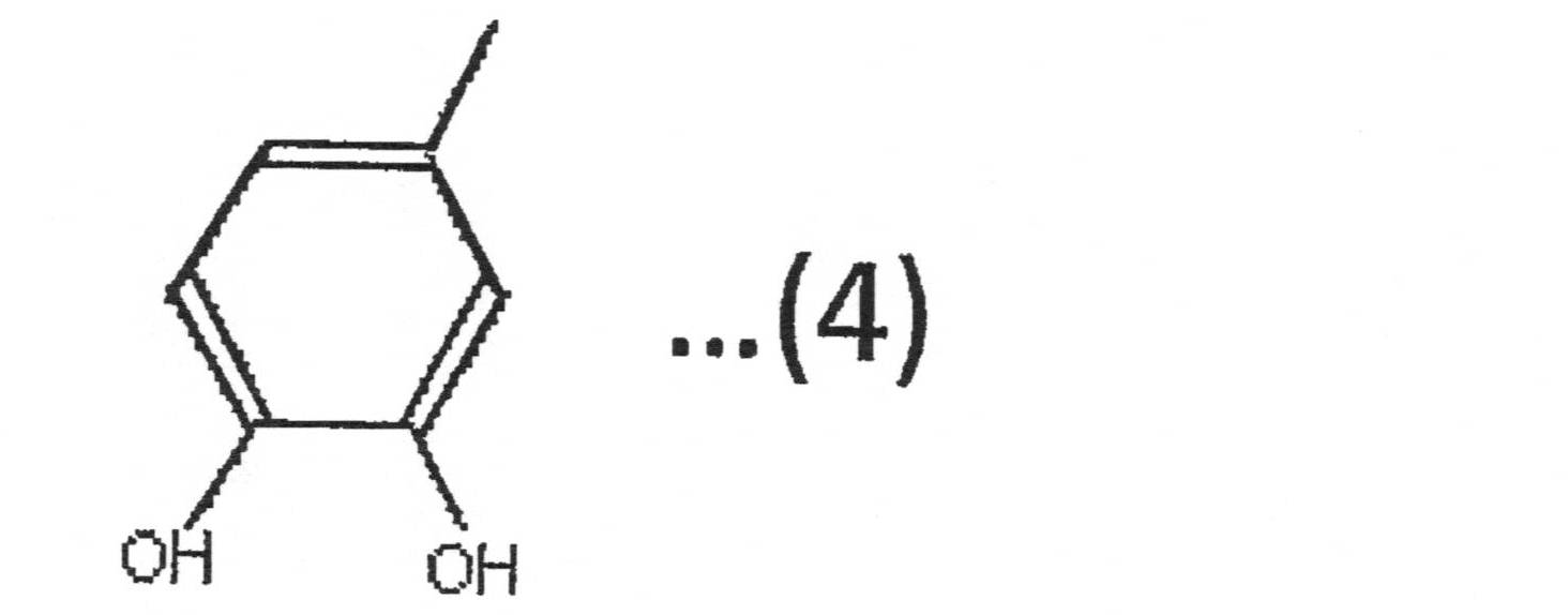
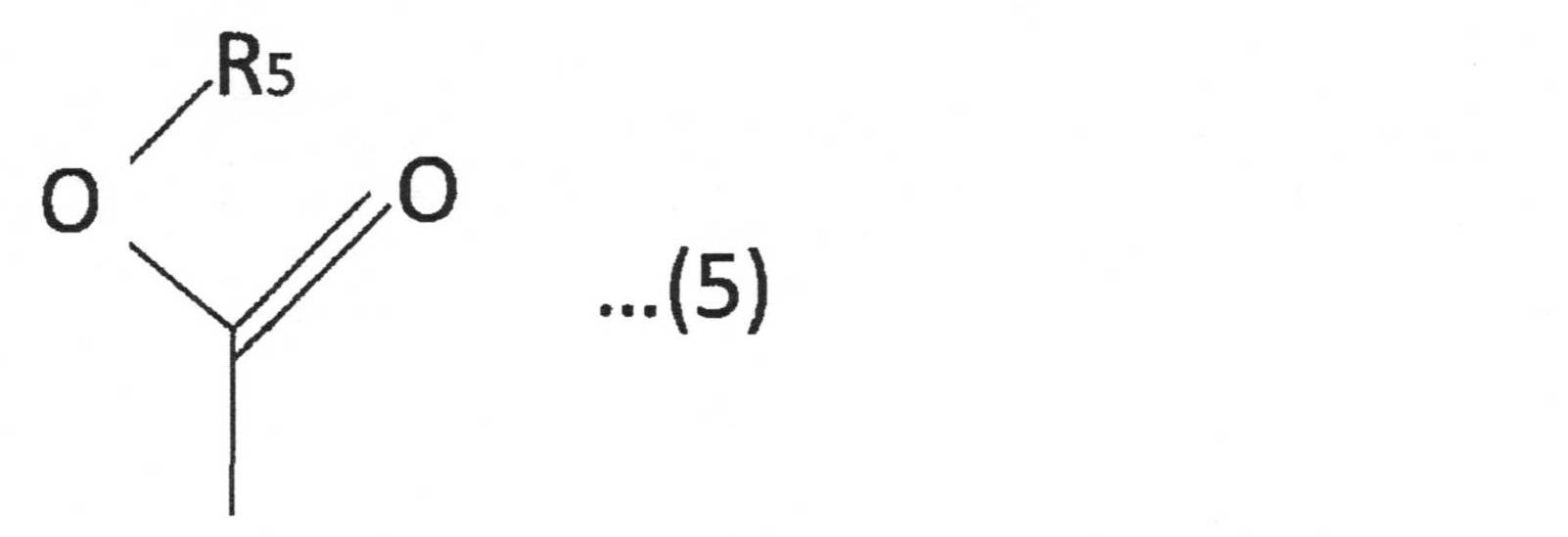
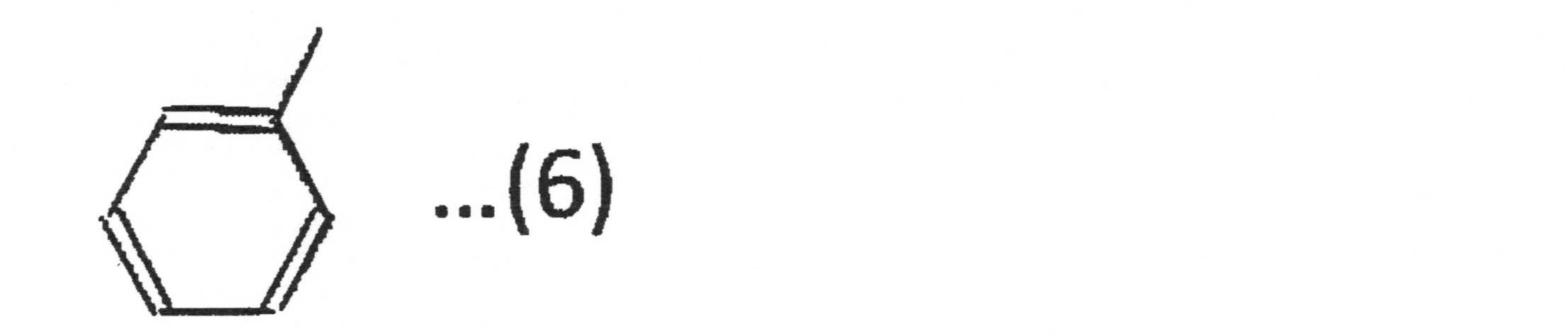
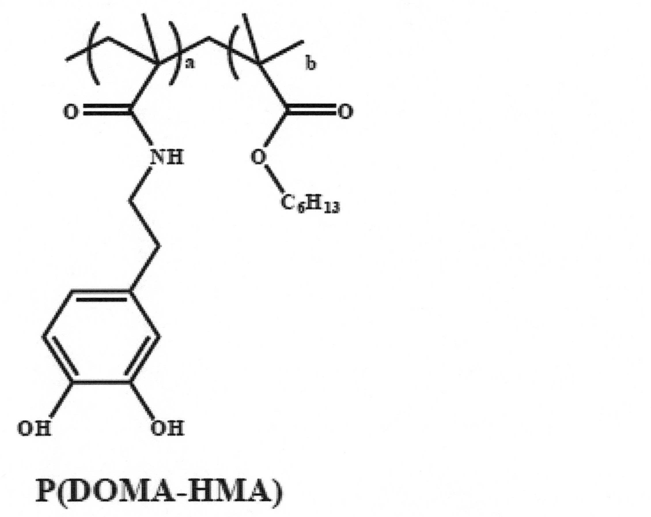
(ナノコーティング材料の製造方法)
次に、本発明のナノコーティング材料の製造方法の一実施形態について説明する。 The nanocoating material of the present invention can be applied to various applications because, for example, an ionic group that assists ion transport, an ethylene glycol group, or the like can be freely introduced. In addition, the nanocoating material of the present invention can impart necessary solubility according to various applications by, for example, controlling the catechol group counterpart.
(Manufacturing method of nano coating material)
Next, an embodiment of the method for producing a nanocoating material of the present invention will be described.
この工程では、第1のモノマーと、第2のモノマーを有機溶媒に分散して、モノマー分散溶液を調製する。 (Monomer dispersion solution preparation step S1)
In this step, the first monomer and the second monomer are dispersed in an organic solvent to prepare a monomer dispersion solution.
(モノマー重合工程S2)
この工程では、前記モノマー分散溶液中のモノマーを重合させる。 In these examples, the hydrophobic second side chain R 2 is a methyl-ester group or a phenyl group. Instead of the methyl group of the methyl-ester group, a hydroxyl group or a linear or branched alkyl group having 1 to 12 carbon atoms may be used. By having these hydrophobic second side chains R 2 , water repellent efficiency can be achieved.
(Monomer polymerization step S2)
In this step, the monomer in the monomer dispersion solution is polymerized.
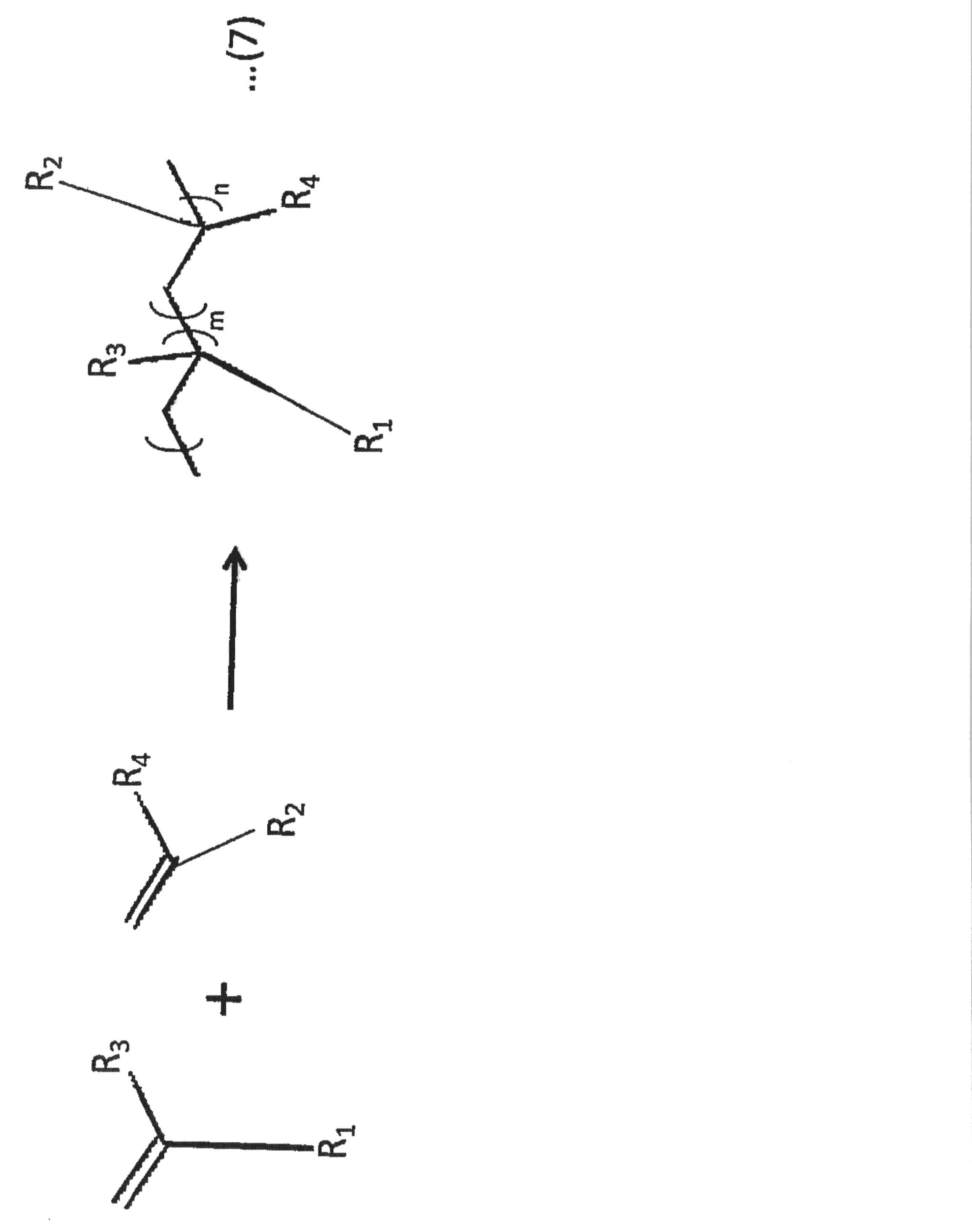
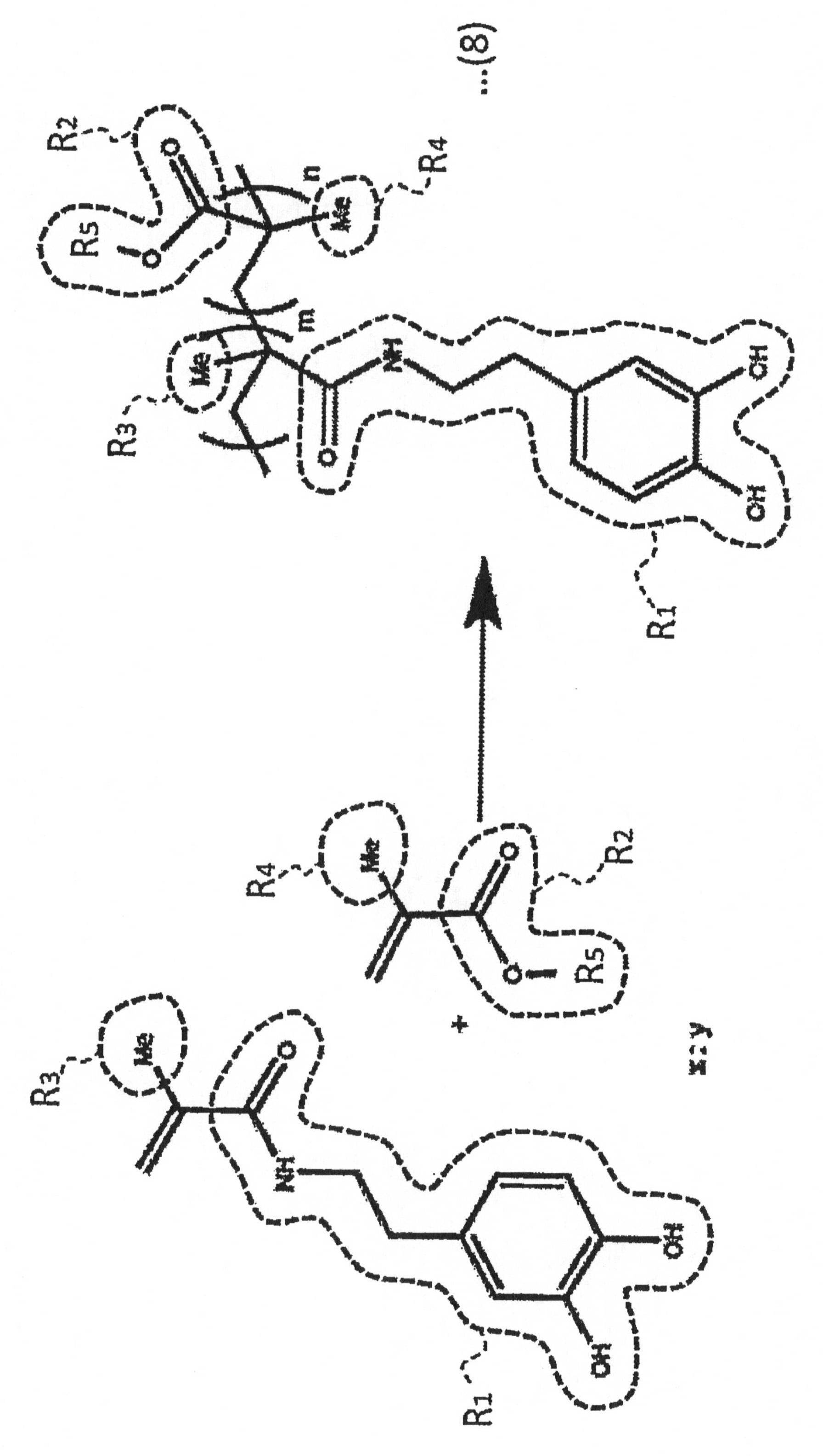
(ナノコーティング膜)
次に、本発明の機能性材料の一実施形態について説明する。図2は、本発明の機能性材料の一実施形態を示す平面図(a)と、(a)のA-A’線における断面図(b)である。 Instead of or in combination with the heat polymerization reaction, a photopolymerization initiator may be used for the photopolymerization reaction.
(Nano coating film)
Next, an embodiment of the functional material of the present invention will be described. FIG. 2A is a plan view showing an embodiment of the functional material of the present invention, and FIG. 2B is a cross-sectional view taken along line AA ′ in FIG.
(ナノコーティング膜の接着原理)
図3は、図2(b)のB部拡大概略図であって、ナノコーティング膜11として前記の化学式(2)、(4)に示すナノコーティング材料を用い、金属/金属合金基材12としてMg金属またはMg合金を用いた場合のナノコーティング膜の接着原理の一例を示した図である。 In addition, it is preferable that the nanocoating film |
(Adhesion principle of nano coating film)
FIG. 3 is an enlarged schematic view of part B of FIG. 2B, wherein the nanocoating material shown in the chemical formulas (2) and (4) is used as the
次に、本発明の機能性材料の製造方法の一実施形態について説明する。 (Method for producing functional materials)
Next, an embodiment of the method for producing a functional material of the present invention will be described.
この工程では、ナノコーティング材料を有機溶媒に分散し、ナノコーティング材料分散液を調製する。この分散液には、必要に応じて各種の添加剤を加えてもよい。このような添加剤は、例えば、粘度調整剤や光劣化防止剤、抗酸化剤、着色剤等であって、防錆ナノコーティング膜の使用環境、用途目的等を考慮して選択することができる。 (Nano-coating material dispersion preparation process F1)
In this step, the nanocoating material is dispersed in an organic solvent to prepare a nanocoating material dispersion. Various additives may be added to the dispersion as necessary. Such additives are, for example, a viscosity modifier, a photodegradation inhibitor, an antioxidant, a colorant, and the like, and can be selected in consideration of the usage environment, purpose of use, etc. of the rust-proof nanocoating film. .
この工程では、ナノコーティング材料分散液を、例えば湿式塗布法により基材表面に塗布してから、乾燥して、ナノコーティング膜を成膜する。ナノコーティング膜は、平滑膜として成膜できる。 (Film formation process F2)
In this step, the nano-coating material dispersion is applied to the surface of the substrate by, for example, a wet application method, and then dried to form a nano-coating film. The nanocoating film can be formed as a smooth film.
(A)少なくとも一組の隣接水酸基を持つベンゼン環を含む接合基を有する第1の側鎖または末端と、
(B)親水性の第2の側鎖と
を有している。 That is, the nanocoating material of another embodiment has a polymer main chain,
(A) a first side chain or terminal having a bonding group comprising a benzene ring having at least one pair of adjacent hydroxyl groups;
(B) It has a hydrophilic second side chain.


(材料調製・特性評価)
次の化学反応式(9)に示したように、第1の原料モノマーである材料(DOMA1)と、第2の原料モノマーである材料(メチルメタクリレート)とを仕込み比(x:y)を(1:2.5)で混合してから、ラジカル開始剤であるAIBNとともに、DMF中に分散してモノマー分散溶液を調製してから、75℃で、40時間、かき混ぜながら、前記モノマー分散溶液を、フリーラジカル重合反応(Free radical polymerization)させた。DMF中のAIBN濃度は1.5mol%とした。 <Example 1>
(Material preparation / characteristic evaluation)
As shown in the following chemical reaction formula (9), the charging ratio (x: y) of the material (DOMA1) as the first raw material monomer and the material (methyl methacrylate) as the second raw material monomer is ( 1: 2.5) and then mixed in DMF together with AIBN, which is a radical initiator, to prepare a monomer dispersion solution. Then, the monomer dispersion solution was stirred at 75 ° C. for 40 hours while stirring. , Free radical polymerization reaction (Free radical polymerization). The AIBN concentration in DMF was 1.5 mol%.
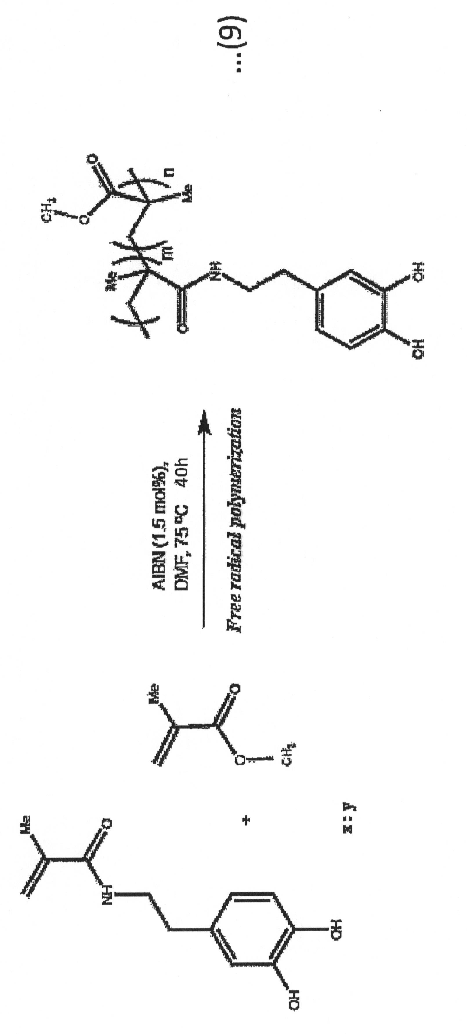
前記仕込み比を1:5とした他は実施例1試料と同様にして、実施例2試料を作成した。 <Example 2>
An Example 2 sample was prepared in the same manner as the Example 1 sample except that the charge ratio was 1: 5.
前記仕込み比(x:y)を1:10とした他は実施例1試料と同様にして、実施例3試料を作成した。 <Example 3>
Example 3 sample was prepared in the same manner as Example 1 except that the charging ratio (x: y) was 1:10.
次の化学反応式(10)に示したように、第2の原料モノマーを材料(ヘキシル メタクリレート)とし、前記仕込み比(x:y)を1:1とした他は実施例1試料と同様にして、実施例4試料を作成した。 <Example 4>
As shown in the following chemical reaction formula (10), the second raw material monomer was used as a material (hexyl methacrylate), and the charge ratio (x: y) was changed to 1: 1, as in the sample of Example 1. Thus, a sample of Example 4 was prepared.
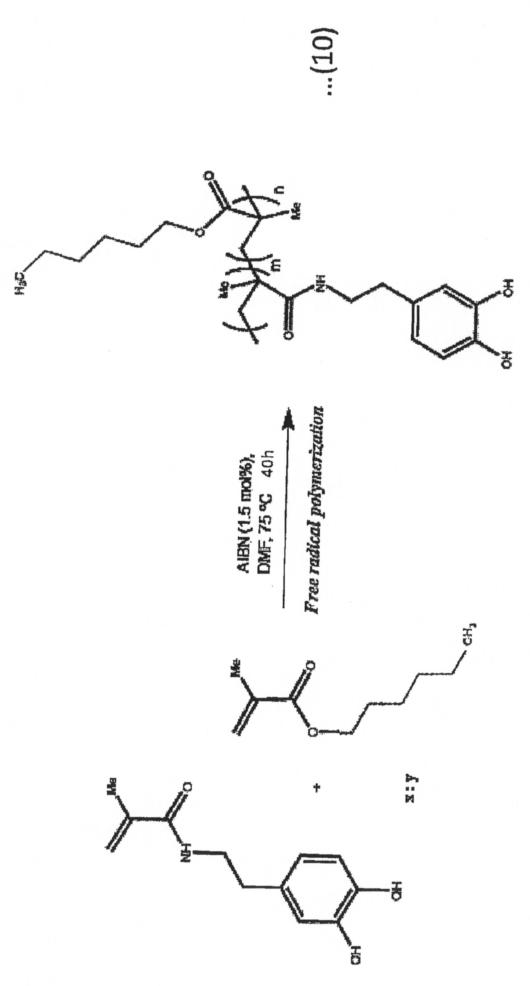
第2の原料モノマーを実施例4と同様の材料(ヘキシル メタクリレート)とし、前記仕込み比(x:y)を1:2とした他は実施例1試料と同様にして、実施例5試料を作成した。 <Example 5>
A sample of Example 5 was prepared in the same manner as the sample of Example 1 except that the second raw material monomer was the same material (hexyl methacrylate) as in Example 4 and the charge ratio (x: y) was 1: 2. did.
第2の原料モノマーを実施例4と同様の材料(ヘキシル メタクリレート)とし、前記仕込み比(x:y)を1:4とした他は実施例1試料と同様にして、実施例6試料を作成した。 <Example 6>
A sample of Example 6 is prepared in the same manner as the sample of Example 1 except that the second raw material monomer is the same material (hexyl methacrylate) as in Example 4 and the charging ratio (x: y) is 1: 4. did.
化学反応式(9)に示すフリーラジカル重合反応時間を24時間とした他は実施例2試料と同様にして、実施例7試料を作成した。 <Example 7>
A sample of Example 7 was prepared in the same manner as the sample of Example 2 except that the free radical polymerization reaction time shown in the chemical reaction formula (9) was 24 hours.
化学反応式(9)に示すフリーラジカル重合反応時間を24時間とした他は実施例3試料と同様にして、実施例8試料を作成した。 <Example 8>
An Example 8 sample was prepared in the same manner as the Example 3 sample except that the free radical polymerization reaction time shown in the chemical reaction formula (9) was 24 hours.
仕込み比(x:y)を1:30とした他は実施例8試料と同様にして、実施例9試料を作成した。 <Example 9>
An Example 9 sample was prepared in the same manner as the Example 8 sample except that the charging ratio (x: y) was set to 1:30.
仕込み比(x:y)を1:90とした他は実施例8試料と同様にして、実施例10試料を作成した。 <Example 10>
A sample of Example 10 was prepared in the same manner as the sample of Example 8 except that the charging ratio (x: y) was 1:90.
化学反応式(10)に示すフリーラジカル重合反応時間を24時間とした他は実施例6試料と同様にして、実施例11試料を作成した。 <Example 11>
A sample of Example 11 was prepared in the same manner as the sample of Example 6 except that the free radical polymerization reaction time shown in the chemical reaction formula (10) was 24 hours.
次の化学反応式(11)に示したように、第2の原料モノマーを材料(ドデシル メタクリレート)とし、フリーラジカル重合反応時間を24時間とし、前記仕込み比(x:y)を1:3とした他は実施例1試料と同様にして、実施例12試料を作成した。 <Example 12>
As shown in the following chemical reaction formula (11), the second raw material monomer is a material (dodecyl methacrylate), the free radical polymerization reaction time is 24 hours, and the charging ratio (x: y) is 1: 3. A sample of Example 12 was prepared in the same manner as the sample of Example 1 except that.
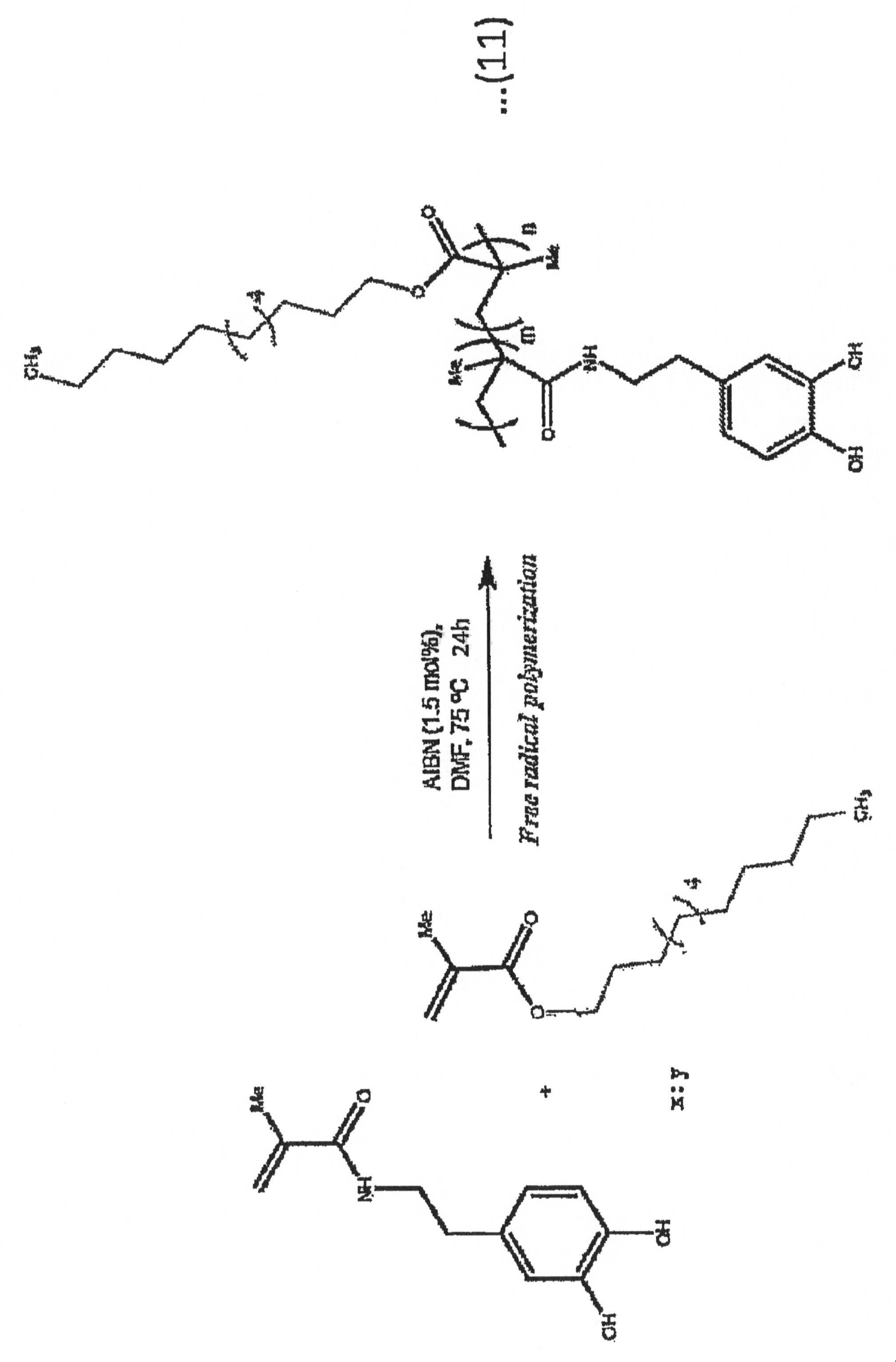
次の化学反応式(12)に示したように、第2の原料モノマーを材料(スチレン)とし、フリーラジカル重合反応時間を24時間とし、前記仕込み比(x:y)を1:7とした他は実施例1試料と同様にして、実施例13試料を作成した。 <Example 13>
As shown in the following chemical reaction formula (12), the second raw material monomer is a material (styrene), the free radical polymerization reaction time is 24 hours, and the charging ratio (x: y) is 1: 7. Example 13 sample was prepared in the same manner as Example 1 sample.

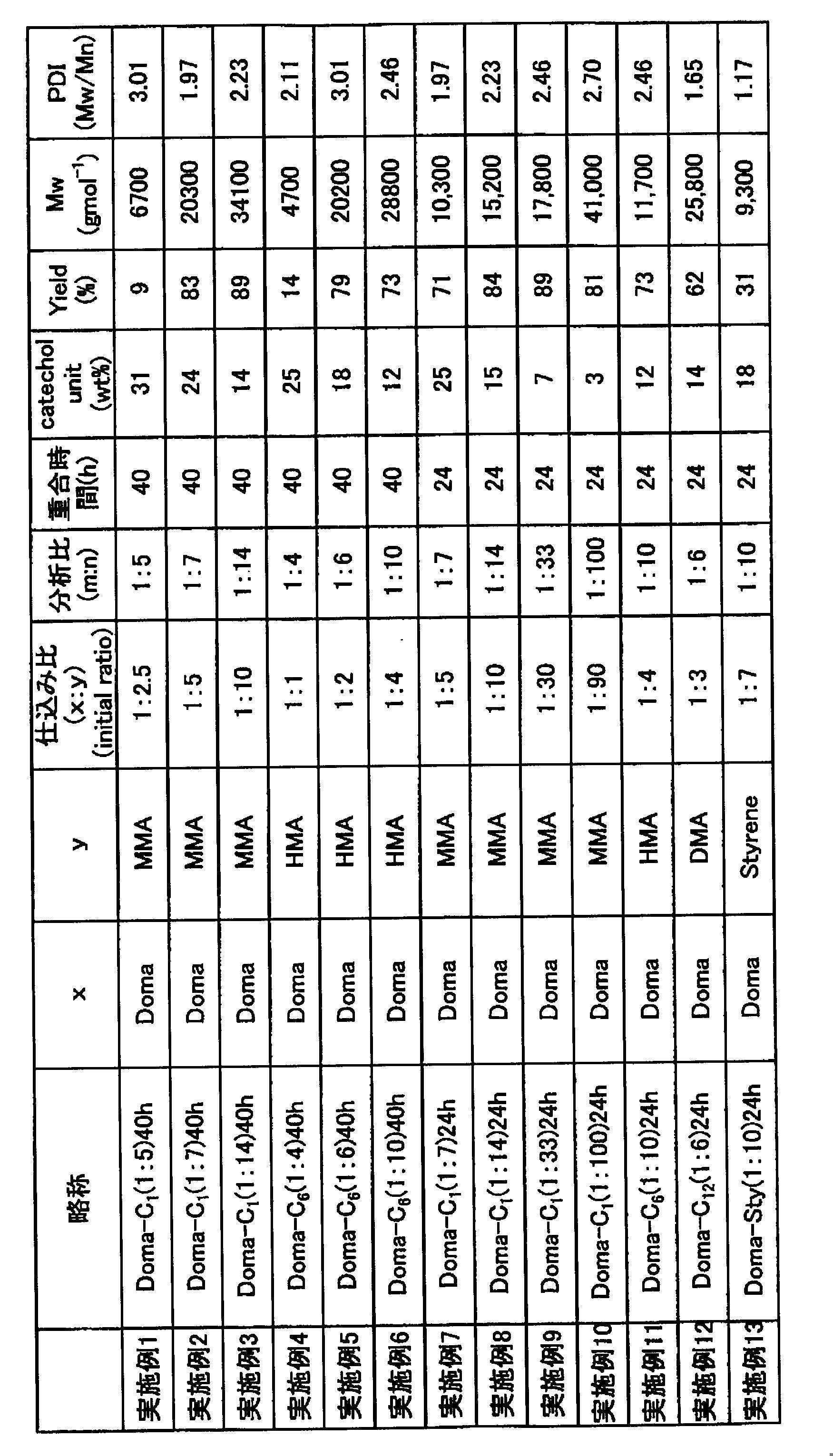
(円板試験片の作製)
次に、Mg合金棒(市販品、Mg-Al3%-Zn1%合金、Mg alloy(AZ31)、直径1.5cm)を切断し、Mg合金円板を作製した。厚さは4mmとした。 <Test piece preparation and rust evaluation>
(Production of disk specimen)
Next, an Mg alloy rod (commercial product, Mg—
次に、実施例1試料を8wt%の割合でTHF中に分散し、分散液を調製した。 (Production of Example 1 test piece)
Next, the sample of Example 1 was dispersed in THF at a rate of 8 wt% to prepare a dispersion.
実施例2~13試料を用いた他は実施例1試験片と同様にして、実施例2~13試験片を作製した。 (Preparation of test pieces of Examples 2 to 13)
Examples 2 to 13 Test pieces were prepared in the same manner as the Example 1 test piece except that the
円板試験片を比較例1試験片とした。これは、コーティング膜を成膜しない条件を測定するための試験片である。 (Preparation of Comparative Example 1 Specimen)
The disc specimen was used as a comparative example 1 specimen. This is a test piece for measuring conditions in which a coating film is not formed.
PMMA(ポリメタクリル酸メチル樹脂)を用いた他は実施例1試験片と同様にして、比較例2試験片を作製した。
PMMA8wt%溶液を用いて成膜した。 (Comparative Example 2 Preparation of Test Piece)
A Comparative Example 2 test piece was prepared in the same manner as in the Example 1 test piece except that PMMA (polymethyl methacrylate resin) was used.
A film was formed using a
図17は、各試験片を酸性バッファー水溶液(pH5)中に浸漬したときに発生する水素の水素発生量と浸漬時間との関係を示すグラフである。 (Rust evaluation)
FIG. 17 is a graph showing the relationship between the hydrogen generation amount of hydrogen generated when each test piece is immersed in an acidic buffer aqueous solution (pH 5) and the immersion time.

(円板試験片の作製)
次に、Mg合金棒(市販品、Mg-Al3%-Zn1%合金、Mg alloy(AZ31)、直径1.5cm)を切断し、Mg合金円板を作製した。厚さは4mmとした。 (Production of Example 7 (dip) test piece)
(Production of disk specimen)
Next, an Mg alloy rod (commercial product, Mg—
まず、表面をSEM観察した。図21は、実施例7(dip)試験片の表面のSEM像写真であり、表面コート前(a)と表面コート後(b)である。 (Surface evaluation of Example 7 (dip) test piece)
First, the surface was observed by SEM. FIG. 21 is a SEM image photograph of the surface of the test piece of Example 7 (dip), which is before surface coating (a) and after surface coating (b).
(円板試験片の作製)
円板試験片を作製してから、スピンコーティング法による成膜を行い、これを60℃で加熱乾燥処理して、実施例7(spin)試験片を作製した。成膜条件は(1000rpm、15secに引き続き2500rpm、30sec)である。 (Production of Example 7 (spin) test piece)
(Production of disk specimen)
After producing the disk test piece, film formation was performed by a spin coating method, and this was heat-dried at 60 ° C. to produce an Example 7 (spin) test piece. The film forming conditions are (1000 rpm, 15 sec, followed by 2500 rpm, 30 sec).
実施例11試料を用いた他は実施例7(spin)試験片と同様にして、実施例11(spin)試験片を作製した。 (Production of Example 11 (spin) test piece)
An Example 11 (spin) test piece was prepared in the same manner as the Example 7 (spin) test piece except that the sample of Example 11 was used.
実施例12試料を用いた他は実施例7(spin)試験片と同様にして、実施例12(spin)試験片を作製した。 (Production of Example 12 (spin) test piece)
An Example 12 (spin) test piece was prepared in the same manner as the Example 7 (spin) test piece except that the sample of Example 12 was used.

(H2発生量)
次に、実施例7(spin)、11(spin)、12(spin)、比較例1、2試験片をそれぞれ酸性水溶液(pH5)に長期間浸漬して、H2発生量測定を行った。 (Rust evaluation by immersion in acidic aqueous solution (pH 5))
(H 2 generation amount)
Next, Examples 7 (spin), 11 (spin), 12 (spin), and Comparative Examples 1 and 2 were immersed in an acidic aqueous solution (pH 5) for a long period of time, and the amount of H 2 generated was measured.
図26は、比較例1試験片(Uncoated)の一部分のSEM像であって、酸性水溶液(pH5)に浸漬前(a)、12時間浸漬後(b)である。挿入図は、試験片全体のデジタル写真である。比較例1試験片では、酸性水溶液(pH5)に12時間浸漬することにより、表面全体に細かな亀裂が生じた。 (Partial SEM image, whole digital photo)
FIG. 26 is an SEM image of a part of the test piece (Uncoated) of Comparative Example 1, which is before immersion (a) and after immersion for 12 hours (b) in an acidic aqueous solution (pH 5). The inset is a digital photograph of the entire specimen. In the test piece of Comparative Example 1, fine cracks were generated on the entire surface by immersion in an acidic aqueous solution (pH 5) for 12 hours.
次に、実施例7(spin)試験片、比較例2試験片にそれぞれクロスカットを入れ、酸性水溶液(pH5)に長期間浸漬して、H2発生量測定を行った。 (Digital photograph of the entire test piece by cross-cut test)
Next, crosscuts were put into the Example 7 (spin) test piece and the Comparative Example 2 test piece, respectively, and immersed in an acidic aqueous solution (pH 5) for a long period of time to measure the amount of H 2 generation.
(部分SEM像、全体のデジタル写真)
図32は、比較例1試験片(Uncoated)の一部分のSEM像であって、3.5wt%NaCl溶液に3日間浸漬後である。挿入図は、試験片全体のデジタル写真である。比較例1試験片では、3.5wt%NaCl溶液に3日間浸漬することにより、表面全体に細かな亀裂が生じた。 (Rust evaluation by immersion in acidic aqueous solution (pH 5))
(Partial SEM image, whole digital photo)
FIG. 32 is an SEM image of a portion of Comparative Example 1 test piece (Uncoated), after being immersed in a 3.5 wt% NaCl solution for 3 days. The inset is a digital photograph of the entire specimen. In the test piece of Comparative Example 1, fine cracks were generated on the entire surface when immersed in a 3.5 wt% NaCl solution for 3 days.
次に、実施例7(spin)試験片、比較例2試験片にそれぞれクロスカットを入れ、3.5wt%NaCl溶液に2日間浸漬した。 (Digital photograph of the entire test piece by cross-cut test)
Next, each of the Example 7 (spin) test piece and the Comparative Example 2 test piece was cross-cut and immersed in a 3.5 wt% NaCl solution for 2 days.
次に、電気化学試験を行った。 (Electrochemical test)
Next, an electrochemical test was performed.
(円板試験片の作製)
まず、Mg合金棒(市販品、Mg-Al3%-Zn1%合金、Mg alloy(AZ31)、直径1.5cm)を切断し、Mg合金円板を作製した。 (Test specimen preparation, rust evaluation, metal material dependency evaluation)
(Production of disk specimen)
First, an Mg alloy rod (commercial product, Mg—Al3% —Zn1% alloy, Mg alloy (AZ31), diameter 1.5 cm) was cut to produce a Mg alloy disk.
(実施例7(spin)試験片の作製)と同様に、円板試験片(Mg合金)を作製してから、スピンコーティング法による成膜(1000rpm、15secに引き続き2500rpm、30sec)を行い、これを60℃で加熱乾燥処理して、実施例7試験片(Mg合金)を作製した。これは、金属材料依存性を調べるために作製したサンプルであって、実施例7(spin)試験片と同一物である。 (Preparation of Example 7 test piece (Mg, Cu, Al, Fe))
Similar to (Preparation of Example 7 (spin) test piece), a disk test piece (Mg alloy) was prepared, and then film formation by spin coating (1000 rpm, 15 sec followed by 2500 rpm, 30 sec) was performed. Was heat-dried at 60 ° C. to prepare a test piece of Example 7 (Mg alloy). This is a sample prepared for examining the dependency on the metal material, and is the same as that of Example 7 (spin) test piece.
次に、先の電気化学試験の説明図(図37)に示す方法で、電気化学試験を行った。 (Electrochemical test)
Next, an electrochemical test was performed by the method shown in the explanatory diagram of the previous electrochemical test (FIG. 37).
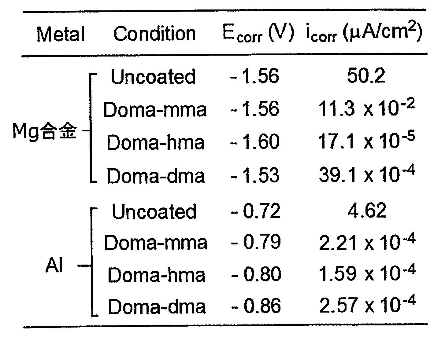
(材料調整・特性評価)
化学反応式(10)に示すフリーラジカル重合反応温度を24時間とした他は実施例5試料と同様にして、実施例14試料を作成した。 <Example 14>
(Material adjustment / characteristic evaluation)
Example 14 sample was prepared in the same manner as Example 5 sample except that the free radical polymerization reaction temperature shown in chemical reaction formula (10) was 24 hours.
実施例14試料により上記同様コーティング処理をガラス基板およびMg基板の各々に対して行った。 (Scotch tape test)
Example 14 The coating process was performed on each of the glass substrate and the Mg substrate in the same manner as described above.
ガラス基板上に実施例14試料によるコーティング膜を成膜し、異なるpH水溶液に浸漬した後に蒸留水で洗浄し、N2ガスフロート下に乾燥した場合の静的水接触角について測定した。 (Contact angle test)
A coating film of Example 14 was formed on a glass substrate, immersed in a different pH aqueous solution, washed with distilled water, and measured for a static water contact angle when dried under an N 2 gas float.
(材料調整・物性評価)
化学反応式(9)(10)(11)に示すフリーラジカル重合反応の時間を24時間、AlBN使用量を1mol%として、表5に結果を示した。重合反応を行った。 <Example 15>
(Material adjustment and physical property evaluation)
The results are shown in Table 5, assuming that the time of the free radical polymerization reaction shown in the chemical reaction formulas (9), (10) and (11) is 24 hours and the amount of AlBN used is 1 mol%. A polymerization reaction was performed.
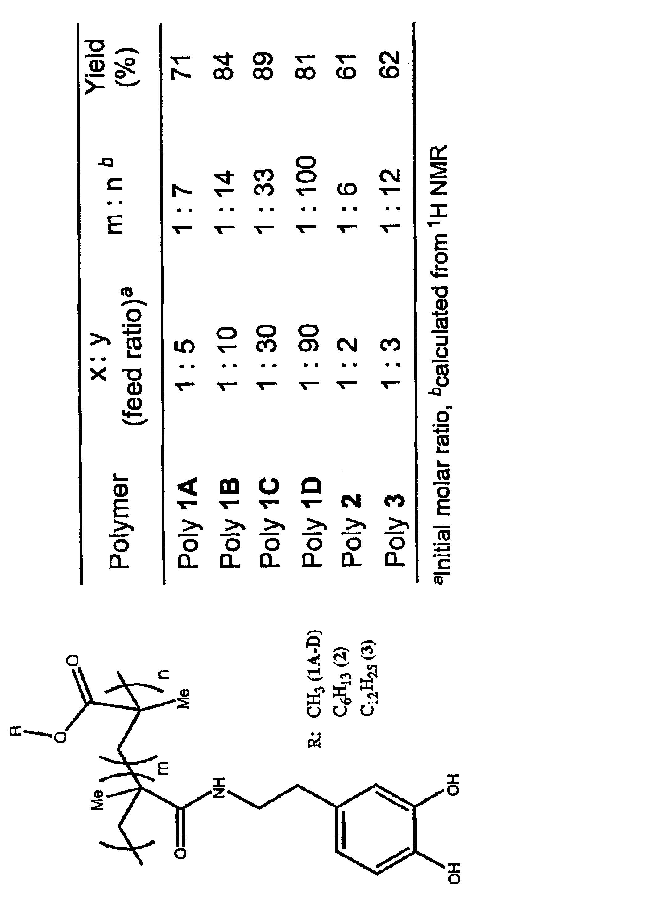
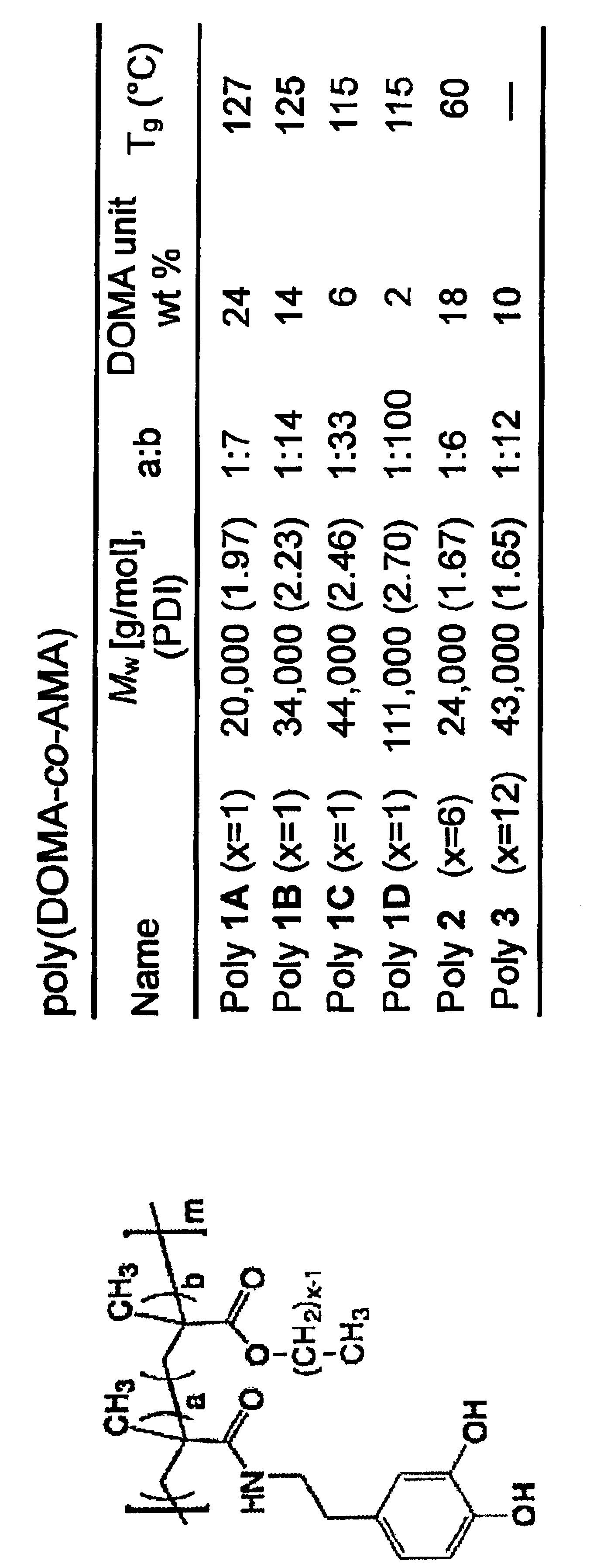
<実施例16>
(1)P(DOMA-DMAEMA)の合成
N-(3,4-dihydroxyphenethyl)methacrylamide(DOMA)と2-(Dimethylamino)ethyl methacrylate(DMAEMA)は、azoisobutyronitrile (AIBN)を用いたフリーラジカル重合で合成した。100 ml 二口フラスコ中に、DOMA単量体 (444 mg , 2 mM)とAIBN(3 mol%)を加え、アルゴンガスで30分間 3 回パージを行った。15 ml の脱水 dimethylformamide(DMF)をフラスコ中に加え、スターラーバーで撹拌した。この混合溶液をアルゴンガスで30分間置換した後、DMAEMA (1. 57 g, 10 mM)をシリンジで加えた。さらに、10分間アルゴン置換を行った後、フラスコを75°Cのオイルバス中に入れ、18時間撹拌した。その後、反応溶液を室温まで冷まし、DMFを減圧除去した。得られた生成物はメタノールに溶解し、石油エーテルで再沈殿を行った。得られた沈殿物はそのまま2-3時間撹拌し、上清をデカンテーションで除去した。さらにモノマー成分を除去するため、再沈殿のプロセスを3回繰り返した。 最終生成物は、白色粉末のポリマーとし得られた。さらに、メタノールにポリマーを溶解し、限外分子量2000Daの透析膜を用いて透析を行ったのち、得られたポリマーを乾燥した(収量1.86 g)。
(2) P(DOMA-PEGMA) の合成
Dopamine methacrylamide (DOMA) と Poly(ethylene glycol) monomethyl ether methacylate (PEGMA)はAIBNを用いたフリーラジカル重合で合成した。100 ml の二口フラスコ中にDOMA モノマー(444 mg , 2 mM )とAIBN(3 mol%)を加え、アルゴンで30分間、3回パージした後、脱水ジメチルホルムアミド(DMF) 15 mlを反応容器に加えた.反応溶液は30分間アルゴンガスで置換し、PEGMA (3 g, 6.32 mM) をシリンジで加えた。その後、アルゴン置換を15 分間続け、75 0C のオイルバス中で18時間反応させた後、反応混合液を室温まで冷却した。得られた反応溶液を濃縮し、ジエチルエーテル中に添加して再沈殿させた。沈殿物を2-3時間撹拌し、上澄みはデカンテーションした後、ジエチルエーテルで再度、再沈殿を行った。得られた生成物は粘調性のゲルとして得られた(収量 3.88 g)。 FIG. 48 shows (a) a TGA curve and (b) a DSC thermogram (second heating cycle) for each of these samples. FIG. 49 shows (a) a comparison of FT-IR spectra, (b) the relationship between the polymer concentration measured by the surface profiler and the thickness of the coating film, and (c) the static water contact angle.
<Example 16>
(1) Synthesis of P (DOMA-DMAEMA)
N- (3,4-dihydroxyphenethyl) methacrylamide (DOMA) and 2- (Dimethylamino) ethyl methacrylate (DMAEMA) were synthesized by free radical polymerization using azoisobutyronitrile (AIBN). In a 100 ml two-necked flask, DOMA monomer (444 mg, 2 mM) and AIBN (3 mol%) were added and purged with argon gas for 30 minutes three times. 15 ml of dehydrated dimethylformamide (DMF) was added to the flask and stirred with a stir bar. After this mixed solution was replaced with argon gas for 30 minutes, DMAEMA (1.57 g, 10 mM) was added by a syringe. Further, after replacing with argon for 10 minutes, the flask was placed in a 75 ° C. oil bath and stirred for 18 hours. Thereafter, the reaction solution was cooled to room temperature, and DMF was removed under reduced pressure. The obtained product was dissolved in methanol and reprecipitated with petroleum ether. The resulting precipitate was stirred as it was for 2-3 hours, and the supernatant was removed by decantation. Further, the reprecipitation process was repeated three times to remove monomer components. The final product was obtained as a white powder polymer. Further, the polymer was dissolved in methanol, dialyzed using a dialysis membrane having an ultra-molecular weight of 2000 Da, and the obtained polymer was dried (yield 1.86 g).
(2) Synthesis of P (DOMA-PEGMA) Dopamine methacrylamide (DOMA) and poly (ethylene glycol) monomethyl ether methacylate (PEGMA) were synthesized by free radical polymerization using AIBN. Add DOMA monomer (444 mg, 2 mM) and AIBN (3 mol%) into a 100 ml two-necked flask, purge with argon for 30 minutes three times, and then add 15 ml of dehydrated dimethylformamide (DMF) to the reaction vessel. The reaction solution was replaced with argon gas for 30 minutes, and PEGMA (3 g, 6.32 mM) was added by syringe. Thereafter, continued argon for 15 minutes, allowed to react for 18 hours at 75 0 C in an oil bath, the reaction mixture was cooled to room temperature. The resulting reaction solution was concentrated and added to diethyl ether for reprecipitation. The precipitate was stirred for 2-3 hours, and the supernatant was decanted and then reprecipitated again with diethyl ether. The product obtained was obtained as a viscous gel (yield 3.88 g).
12 基材 11
Claims (20)
- 金属または合金からなる基材の表面に結合するナノコーティング材料であって、
高分子主鎖に、
(A)少なくとも一組の隣接水酸基を持つベンゼン環を含む接合基を有する第1の側鎖または末端、および、
(B)官能性の第2の側鎖
を有する化合物からなることを特徴とするナノコーティング材料。 A nanocoating material that binds to the surface of a substrate made of a metal or alloy,
In the polymer main chain,
(A) a first side chain or terminal having a bonding group comprising a benzene ring having at least one pair of adjacent hydroxyl groups, and
(B) A nanocoating material comprising a compound having a functional second side chain. - 前記第2の側鎖が、疎水性であることを特徴とする請求項1に記載のナノコーティング材料。 The nano-coating material according to claim 1, wherein the second side chain is hydrophobic.
- 前記第2の側鎖が、親水性であることを特徴とする請求項1に記載のナノコーティング材料。 The nano-coating material according to claim 1, wherein the second side chain is hydrophilic.
- 前記高分子主鎖が炭素(C)一重結合からなる高分子鎖であることを特徴とする請求項1に記載のナノコーティング材料。 The nanocoating material according to claim 1, wherein the polymer main chain is a polymer chain composed of a carbon (C) single bond.
- 前記高分子主鎖がアクリルアミドとアクリレートのコポリマーからなることを特徴とする請求項1に記載のナノコーティング材料。 The nano-coating material according to claim 1, wherein the polymer main chain is made of a copolymer of acrylamide and acrylate.
- 前記第1の側鎖の前記接合基がカテコール基を含むことを特徴とする請求項1に記載のナノコーティング材料。 The nanocoating material according to claim 1, wherein the bonding group of the first side chain includes a catechol group.
- 前記第2の側鎖が、炭素(C)数が1以上12以下のアルキル基を有することを特徴とする請求項1に記載のナノコーティング材料。 The nano-coating material according to claim 1, wherein the second side chain has an alkyl group having 1 to 12 carbon atoms (C).
- 前記第2の側鎖が、ベンゼン環を含む官能基を有することを特徴とする請求項1に記載のナノコーティング材料。 The nano-coating material according to claim 1, wherein the second side chain has a functional group containing a benzene ring.
- 金属または合金の表面と結合するナノコーティング材料の製造方法であって、
少なくとも一組の隣接水酸基を持つベンゼン環を含む接合基を有する第1のモノマーと、疎水性基または親水性基を有する第2のモノマーを重合させる重合工程
を含むことを特徴とするナノコーティング材料の製造方法。 A method for producing a nano-coating material that binds to a metal or alloy surface,
A nano-coating material comprising a polymerization step of polymerizing a first monomer having a bonding group containing a benzene ring having at least one pair of adjacent hydroxyl groups and a second monomer having a hydrophobic group or a hydrophilic group Manufacturing method. - 前記第1のモノマーは、アクリルアミド基を有することを特徴とする請求項9に記載のナノコーティング材料の製造方法。 The method for producing a nanocoating material according to claim 9, wherein the first monomer has an acrylamide group.
- 前記第2のモノマーは、メタクリレート基を有することを特徴とする請求項9に記載のナノコーティング材料の製造方法。 The method for producing a nano-coating material according to claim 9, wherein the second monomer has a methacrylate group.
- 前記アクリルアミド基が、水酸基または炭素(C)数が1以上12以下のアルキル基を有することを特徴とする請求項10に記載のナノコーティング材料の製造方法。 The method for producing a nanocoating material according to claim 10, wherein the acrylamide group has a hydroxyl group or an alkyl group having 1 to 12 carbon atoms (C).
- 前記メタクリレート基が水酸基又は炭素(C)数が1以上12以下のアルキル基を有することを特徴とする請求項11に記載のナノコーティング材料の製造方法。 The method for producing a nano-coating material according to claim 11, wherein the methacrylate group has a hydroxyl group or an alkyl group having 1 to 12 carbon atoms (C).
- 前記疎水性基が、炭素(C)数が1以上12以下のアルキル基、または、ベンゼン環を含むことを特徴とする請求項9に記載のナノコーティング材料の製造方法。 The method for producing a nano-coating material according to claim 9, wherein the hydrophobic group includes an alkyl group having 1 to 12 carbon atoms (C) or a benzene ring.
- 前記重合工程では、重合開始剤としてAIBNを用い、加熱反応により、前記第1のモノマーと前記第2のモノマーとを重合させることを特徴とする請求項9に記載のナノコーティング材料の製造方法。 The method for producing a nano-coating material according to claim 9, wherein, in the polymerization step, AIBN is used as a polymerization initiator, and the first monomer and the second monomer are polymerized by a heating reaction.
- 金属または合金からなる基材のコーティング剤であって、請求項1から8のいずれか一項に記載のナノコーティング材料を含むことを特徴とするコーティング剤。 A coating agent for a base material made of a metal or an alloy, comprising the nanocoating material according to any one of claims 1 to 8.
- 金属または合金からなる基材の表面に、請求項1から8のいずれかに記載のナノコーティング材料が結合していることを特徴とする機能性材料。 9. A functional material, wherein the nanocoating material according to any one of claims 1 to 8 is bonded to a surface of a base material made of a metal or an alloy.
- 前記基材の表面には、前記ナノコーティング材料の結合によるナノコーティング膜が形成されており、前記ナノコーティング膜の膜厚が100nm以上1μm未満であることを特徴とする請求項17に記載の機能性材料。 The function according to claim 17, wherein a nanocoating film is formed on the surface of the base material by bonding of the nanocoating material, and the film thickness of the nanocoating film is 100 nm or more and less than 1 μm. Sex material.
- 前記基材が、リチウムイオン電池電極であることを特徴とする請求項17に記載の機能性材料。 The functional material according to claim 17, wherein the base material is a lithium ion battery electrode.
- 請求項1から8のいずれか一項に記載のナノコーティング材料を有機溶媒に分散し、ナノコーティング材料分散液を調製する工程、および
前記ナノコーティング材料分散液を、湿式塗布法により基材表面に塗布した後、乾燥させて、基材表面にナノコーティング材料を結合させる工程
を含むことを特徴とする機能性材料の製造方法。 Dispersing the nanocoating material according to any one of claims 1 to 8 in an organic solvent to prepare a nanocoating material dispersion, and applying the nanocoating material dispersion on a substrate surface by a wet coating method. A method for producing a functional material, comprising: a step of applying and drying to bond a nanocoating material to a surface of a substrate.
Priority Applications (3)
| Application Number | Priority Date | Filing Date | Title |
|---|---|---|---|
| JP2016511896A JP6256960B2 (en) | 2014-03-31 | 2015-03-30 | Nano-coating material and manufacturing method thereof, coating agent, functional material and manufacturing method thereof |
| US15/129,911 US10177383B2 (en) | 2014-03-31 | 2015-03-30 | Nano-coating material, method for manufacturing same, coating agent, functional material, and method for manufacturing same |
| EP15772382.6A EP3127970B1 (en) | 2014-03-31 | 2015-03-30 | Nano-coating material, method for manufacturing same, coating agent, functional material, and method for manufacturing same |
Applications Claiming Priority (4)
| Application Number | Priority Date | Filing Date | Title |
|---|---|---|---|
| JP2014-072029 | 2014-03-31 | ||
| JP2014072029 | 2014-03-31 | ||
| JP2014-125143 | 2014-06-18 | ||
| JP2014125143 | 2014-06-18 |
Publications (1)
| Publication Number | Publication Date |
|---|---|
| WO2015152176A1 true WO2015152176A1 (en) | 2015-10-08 |
Family
ID=54240498
Family Applications (1)
| Application Number | Title | Priority Date | Filing Date |
|---|---|---|---|
| PCT/JP2015/060000 WO2015152176A1 (en) | 2014-03-31 | 2015-03-30 | Nano-coating material, method for manufacturing same, coating agent, functional material, and method for manufacturing same |
Country Status (4)
| Country | Link |
|---|---|
| US (1) | US10177383B2 (en) |
| EP (1) | EP3127970B1 (en) |
| JP (1) | JP6256960B2 (en) |
| WO (1) | WO2015152176A1 (en) |
Cited By (5)
| Publication number | Priority date | Publication date | Assignee | Title |
|---|---|---|---|---|
| CN106833251A (en) * | 2017-01-16 | 2017-06-13 | 常州大学 | A kind of floride-free super-hydrophobic coating and preparation method thereof |
| JP2017125125A (en) * | 2016-01-14 | 2017-07-20 | Jsr株式会社 | Resin composition and photosensitive resin composition, method for producing resist pattern, and touch panel member |
| WO2018221564A1 (en) * | 2017-05-31 | 2018-12-06 | 日立化成株式会社 | Adhesive and structure |
| JP2019531587A (en) * | 2016-10-18 | 2019-10-31 | ジェナックス インコーポレイテッド | Metal nonwoven fabric electrode surface-polymerized with dopamine monomer and surface modification method therefor |
| JPWO2019194047A1 (en) * | 2018-04-04 | 2021-04-30 | 日本化薬株式会社 | Copolymerized Polymers, Adhesive Compositions, and Optical Components Containing them |
Families Citing this family (12)
| Publication number | Priority date | Publication date | Assignee | Title |
|---|---|---|---|---|
| WO2016202582A1 (en) | 2015-06-17 | 2016-12-22 | Clariant International Ltd | Water-soluble or water-swellable polymers as water-loss reducers in cement slurries |
| WO2017004174A1 (en) * | 2015-06-30 | 2017-01-05 | Purdue Research Foundation | Adhesives and methods of making the same |
| US11478178B2 (en) * | 2015-12-08 | 2022-10-25 | Carnegie Mellon University | Electronic structures on swollen hydrogels |
| CN110300573B (en) | 2016-12-12 | 2023-07-25 | 科莱恩国际有限公司 | Use of biobased polymers in cosmetic, dermatological or pharmaceutical compositions |
| CN110267996B (en) | 2016-12-12 | 2022-07-22 | 科莱恩国际有限公司 | Polymers containing certain levels of biobased carbon |
| WO2018108663A1 (en) | 2016-12-15 | 2018-06-21 | Clariant International Ltd | Water-soluble and/or water-swellable hybrid polymer |
| EP3554643A1 (en) | 2016-12-15 | 2019-10-23 | Clariant International Ltd | Water-soluble and/or water-swellable hybrid polymer |
| WO2018108665A1 (en) | 2016-12-15 | 2018-06-21 | Clariant International Ltd | Water-soluble and/or water-swellable hybrid polymer |
| US11339241B2 (en) | 2016-12-15 | 2022-05-24 | Clariant International Ltd. | Water-soluble and/or water-swellable hybrid polymer |
| CN113773419A (en) * | 2020-06-10 | 2021-12-10 | 恒大新能源技术(深圳)有限公司 | Mussel biomimetic polymer and preparation method thereof, positive electrode binder and secondary battery |
| CN113736011B (en) * | 2021-09-28 | 2022-06-10 | 中国科学院兰州化学物理研究所 | Hydrophobic moisture-resistant coating and preparation method and application thereof |
| CN115006606B (en) * | 2022-02-23 | 2023-02-24 | 中国科学院兰州化学物理研究所 | Hydrophilic lubricating coating and preparation method and application thereof |
Citations (14)
| Publication number | Priority date | Publication date | Assignee | Title |
|---|---|---|---|---|
| JPS6239603A (en) * | 1985-08-13 | 1987-02-20 | ヘキスト・アクチエンゲゼルシヤフト | Novel polymer, radiation sensitive mixture containing the same and production of relief image |
| JPH1029292A (en) * | 1996-07-17 | 1998-02-03 | Fuji Photo Film Co Ltd | Negative image recording material |
| WO2003008376A2 (en) * | 2001-07-20 | 2003-01-30 | Northwestern University | Adhesive dopa-containing polymers and related methods of use |
| WO2005070866A2 (en) * | 2004-01-27 | 2005-08-04 | Basf Aktiengesellschaft | Polymer dispersions or solutions comprising 3,4 dihydroxyphenyl groups |
| JP2007527871A (en) * | 2004-02-27 | 2007-10-04 | ノースウエスタン ユニバーシティ | Polymerized compounds and related methods of use |
| WO2009147007A2 (en) * | 2008-06-06 | 2009-12-10 | Universite De Liege | Multifunctional coatings |
| JP2010501027A (en) * | 2006-08-04 | 2010-01-14 | ネリテス コーポレイション | Biomimetic compound and synthesis method thereof |
| CN101704914A (en) * | 2009-11-03 | 2010-05-12 | 深圳市海润德润滑油有限公司 | Waterborne rust conversion polymer emulsion, coating thereof and method for preparing same |
| CN102372817A (en) * | 2010-08-11 | 2012-03-14 | 郁锋 | Preparation method of amide derivative copolymer and application thereof |
| JP2012072440A (en) * | 2010-09-29 | 2012-04-12 | Toagosei Co Ltd | Electroless plating method |
| CN102504082A (en) * | 2011-10-26 | 2012-06-20 | 杭州师范大学 | Poly(propenoyl dopamine), and preparation method and application thereof |
| JP2012216347A (en) * | 2011-03-31 | 2012-11-08 | Daiso Co Ltd | Nonaqueous electrolyte secondary battery |
| JP2012233059A (en) * | 2011-04-28 | 2012-11-29 | Japan Science & Technology Agency | Novel polymer |
| WO2014087817A1 (en) * | 2012-12-05 | 2014-06-12 | 独立行政法人科学技術振興機構 | Resin for nanoimprinting, laminate containing resin for nanoimprinting, printed board containing resin for nanoimprinting, and method for producing nanoimprint substrate |
Family Cites Families (4)
| Publication number | Priority date | Publication date | Assignee | Title |
|---|---|---|---|---|
| US8563117B2 (en) * | 2006-08-04 | 2013-10-22 | Phillip B. Messersmith | Biomimetic modular adhesive complex: materials, methods and applications therefore |
| GB2495951B (en) * | 2011-10-26 | 2014-07-16 | Nexeon Ltd | A composition for a secondary battery cell |
| US9198985B2 (en) * | 2009-05-22 | 2015-12-01 | Vanderbuilt University | Bimodal star polymer architectures as fluorescent and MRI imaging reagents |
| WO2011018980A1 (en) * | 2009-08-10 | 2011-02-17 | 株式会社アルバック | Process for production of thin film lithium secondary battery |
-
2015
- 2015-03-30 JP JP2016511896A patent/JP6256960B2/en active Active
- 2015-03-30 WO PCT/JP2015/060000 patent/WO2015152176A1/en active Application Filing
- 2015-03-30 US US15/129,911 patent/US10177383B2/en active Active
- 2015-03-30 EP EP15772382.6A patent/EP3127970B1/en active Active
Patent Citations (14)
| Publication number | Priority date | Publication date | Assignee | Title |
|---|---|---|---|---|
| JPS6239603A (en) * | 1985-08-13 | 1987-02-20 | ヘキスト・アクチエンゲゼルシヤフト | Novel polymer, radiation sensitive mixture containing the same and production of relief image |
| JPH1029292A (en) * | 1996-07-17 | 1998-02-03 | Fuji Photo Film Co Ltd | Negative image recording material |
| WO2003008376A2 (en) * | 2001-07-20 | 2003-01-30 | Northwestern University | Adhesive dopa-containing polymers and related methods of use |
| WO2005070866A2 (en) * | 2004-01-27 | 2005-08-04 | Basf Aktiengesellschaft | Polymer dispersions or solutions comprising 3,4 dihydroxyphenyl groups |
| JP2007527871A (en) * | 2004-02-27 | 2007-10-04 | ノースウエスタン ユニバーシティ | Polymerized compounds and related methods of use |
| JP2010501027A (en) * | 2006-08-04 | 2010-01-14 | ネリテス コーポレイション | Biomimetic compound and synthesis method thereof |
| WO2009147007A2 (en) * | 2008-06-06 | 2009-12-10 | Universite De Liege | Multifunctional coatings |
| CN101704914A (en) * | 2009-11-03 | 2010-05-12 | 深圳市海润德润滑油有限公司 | Waterborne rust conversion polymer emulsion, coating thereof and method for preparing same |
| CN102372817A (en) * | 2010-08-11 | 2012-03-14 | 郁锋 | Preparation method of amide derivative copolymer and application thereof |
| JP2012072440A (en) * | 2010-09-29 | 2012-04-12 | Toagosei Co Ltd | Electroless plating method |
| JP2012216347A (en) * | 2011-03-31 | 2012-11-08 | Daiso Co Ltd | Nonaqueous electrolyte secondary battery |
| JP2012233059A (en) * | 2011-04-28 | 2012-11-29 | Japan Science & Technology Agency | Novel polymer |
| CN102504082A (en) * | 2011-10-26 | 2012-06-20 | 杭州师范大学 | Poly(propenoyl dopamine), and preparation method and application thereof |
| WO2014087817A1 (en) * | 2012-12-05 | 2014-06-12 | 独立行政法人科学技術振興機構 | Resin for nanoimprinting, laminate containing resin for nanoimprinting, printed board containing resin for nanoimprinting, and method for producing nanoimprint substrate |
Non-Patent Citations (3)
| Title |
|---|
| HIROSHI YABU ET AL.: "Thermal nanoimprint lithography of polymer films on non-adhesive substrates by using mussel-inspired adhesive polymer layers", JOURNAL OF MATERIALS CHEMISTRY C, vol. 1, no. 8, 28 February 2013 (2013-02-28), pages 1558 - 1561, XP055229633, ISSN: 2050-7526 * |
| STEPUK ALEXANDER ET AL.: "Mussel-inspired load bearing metal-polymer glues", CHEMICAL COMMUNICATIONS, vol. 48, no. 50, 25 June 2012 (2012-06-25), pages 6238 - 6240, XP055229631, ISSN: 1359-7345 * |
| YUTA SAITO ET AL.: "Catechol-ki Gan'yu Ryo Shinbaisei Kobunshi ni yoru Hyomen Shushoku Titania Nano Ryushi o Mochiita Kaisoteki Takoshitsumaku no Sakusei", DAI 61 KAI SYMPOSIUM ON MACROMOLECULES YOKOSHU, vol. 61, no. 2, 3U13, 5 September 2012 (2012-09-05), pages 4657 - 4658, XP008181031 * |
Cited By (9)
| Publication number | Priority date | Publication date | Assignee | Title |
|---|---|---|---|---|
| JP2017125125A (en) * | 2016-01-14 | 2017-07-20 | Jsr株式会社 | Resin composition and photosensitive resin composition, method for producing resist pattern, and touch panel member |
| JP2019531587A (en) * | 2016-10-18 | 2019-10-31 | ジェナックス インコーポレイテッド | Metal nonwoven fabric electrode surface-polymerized with dopamine monomer and surface modification method therefor |
| CN106833251A (en) * | 2017-01-16 | 2017-06-13 | 常州大学 | A kind of floride-free super-hydrophobic coating and preparation method thereof |
| CN106833251B (en) * | 2017-01-16 | 2019-12-06 | 常州大学 | fluorine-free super-hydrophobic coating and preparation method thereof |
| WO2018221564A1 (en) * | 2017-05-31 | 2018-12-06 | 日立化成株式会社 | Adhesive and structure |
| CN110546223A (en) * | 2017-05-31 | 2019-12-06 | 日立化成株式会社 | Adhesive and structure |
| JPWO2018221564A1 (en) * | 2017-05-31 | 2020-04-23 | 日立化成株式会社 | Adhesive and structure |
| CN110546223B (en) * | 2017-05-31 | 2021-12-24 | 昭和电工材料株式会社 | Adhesive and structure |
| JPWO2019194047A1 (en) * | 2018-04-04 | 2021-04-30 | 日本化薬株式会社 | Copolymerized Polymers, Adhesive Compositions, and Optical Components Containing them |
Also Published As
| Publication number | Publication date |
|---|---|
| US20170214047A1 (en) | 2017-07-27 |
| JPWO2015152176A1 (en) | 2017-04-13 |
| EP3127970B1 (en) | 2019-08-07 |
| JP6256960B2 (en) | 2018-01-10 |
| EP3127970A4 (en) | 2017-08-30 |
| EP3127970A1 (en) | 2017-02-08 |
| US10177383B2 (en) | 2019-01-08 |
Similar Documents
| Publication | Publication Date | Title |
|---|---|---|
| JP6256960B2 (en) | Nano-coating material and manufacturing method thereof, coating agent, functional material and manufacturing method thereof | |
| Armelin et al. | Corrosion protection with polyaniline and polypyrrole as anticorrosive additives for epoxy paint | |
| Murmu et al. | Amine cured double Schiff base epoxy as efficient anticorrosive coating materials for protection of mild steel in 3.5% NaCl medium | |
| Riaz et al. | Recent advances in corrosion protective composite coatings based on conducting polymers and natural resource derived polymers | |
| Huang et al. | Cardanol-based polybenzoxazine superhydrophobic coating with improved corrosion resistance on mild steel | |
| Zhang et al. | High corrosion protection of a polyaniline/organophilic montmorillonite coating for magnesium alloys | |
| JP3822638B2 (en) | Electroactive polymer coating for corrosion control | |
| Payra et al. | Bioinspired adhesive polymer coatings for efficient and versatile corrosion resistance | |
| Shabani-Nooshabadi et al. | Electropolymerized polyaniline coatings on aluminum alloy 3004 and their corrosion protection performance | |
| Abu-Thabit et al. | Recent advances in polyaniline (PANI)-based organic coatings for corrosion protection | |
| Santos et al. | Synthesis in phytic acid medium and application as anticorrosive coatings of polyaniline-based materials | |
| Ates et al. | The application of polycarbazole, polycarbazole/nanoclay and polycarbazole/Zn-nanoparticles as a corrosion inhibition for SS304 in saltwater | |
| Cao et al. | Bio-inspired polybenzoxazine coating: Anti-corrosion and anti-abrasion performance enhancement through monomer design | |
| Mobin et al. | Anti-corrosive properties of Poly (aniline-co-2, 3-xylidine)/ZnO nanocomposite coating on low-carbon steel | |
| Bahremand et al. | Synthesis of a novel metal-organic nanocomposite film (MONF) with superior corrosion protection performance based on the biomimetic polydopamine (PDA)-based molecules and Sm2O3 particles on the steel surface | |
| Zhu et al. | Perfluorinated lubricant/polypyrrole composite material: Preparation and corrosion inhibition application | |
| Sarıarslan et al. | Electrochemical synthesis and corrosion protection of poly (3-aminophenylboronic acid-co-pyrrole) on mild steel | |
| Cao et al. | A Smart Anticorrosive Epoxy Coating Based on Environmental‐Stimuli‐Responsive Copolymer Assemblies for Controlled Release of Corrosion Inhibitors | |
| Yang et al. | Preparation and characterization of polyaniline-poly (styrene-acrylate) composite latexes | |
| JP2014514446A (en) | Polymer corrosion inhibitors for metal surfaces and their manufacture | |
| Abd El‐Ghaffar et al. | Polyaniline and poly (m‐toluidine) prepared by inverse emulsion pathway as corrosion inhibitors in surface coatings | |
| Aradilla et al. | Application of multilayered particles formed by poly (3, 4‐ethylenedioxythiophene) and poly (N‐methylpyrrole) as anti‐corrosive additives of conventional organic coatings | |
| Li et al. | Polyaniline/Fluorocarbon Composite Emulsion Coatings for Anticorrosion to Mild Steel | |
| Minudri et al. | Poly (ionic liquid) s having coumarate counter-anions as corrosion inhibitors in acrylic UV coatings | |
| Salunkhe et al. | Treatise on conducting polymers for corrosion protection–Advanced approach |
Legal Events
| Date | Code | Title | Description |
|---|---|---|---|
| 121 | Ep: the epo has been informed by wipo that ep was designated in this application |
Ref document number: 15772382 Country of ref document: EP Kind code of ref document: A1 |
|
| ENP | Entry into the national phase |
Ref document number: 2016511896 Country of ref document: JP Kind code of ref document: A |
|
| WWE | Wipo information: entry into national phase |
Ref document number: 15129911 Country of ref document: US |
|
| NENP | Non-entry into the national phase |
Ref country code: DE |
|
| REEP | Request for entry into the european phase |
Ref document number: 2015772382 Country of ref document: EP |
|
| WWE | Wipo information: entry into national phase |
Ref document number: 2015772382 Country of ref document: EP |