WO2015151507A1 - レーダーモジュール、輸送機器、及び物体識別方法 - Google Patents
レーダーモジュール、輸送機器、及び物体識別方法 Download PDFInfo
- Publication number
- WO2015151507A1 WO2015151507A1 PCT/JP2015/001847 JP2015001847W WO2015151507A1 WO 2015151507 A1 WO2015151507 A1 WO 2015151507A1 JP 2015001847 W JP2015001847 W JP 2015001847W WO 2015151507 A1 WO2015151507 A1 WO 2015151507A1
- Authority
- WO
- WIPO (PCT)
- Prior art keywords
- unit
- target object
- signal
- radar module
- warning
- Prior art date
Links
Images


Classifications
-
- G—PHYSICS
- G01—MEASURING; TESTING
- G01S—RADIO DIRECTION-FINDING; RADIO NAVIGATION; DETERMINING DISTANCE OR VELOCITY BY USE OF RADIO WAVES; LOCATING OR PRESENCE-DETECTING BY USE OF THE REFLECTION OR RERADIATION OF RADIO WAVES; ANALOGOUS ARRANGEMENTS USING OTHER WAVES
- G01S13/00—Systems using the reflection or reradiation of radio waves, e.g. radar systems; Analogous systems using reflection or reradiation of waves whose nature or wavelength is irrelevant or unspecified
- G01S13/88—Radar or analogous systems specially adapted for specific applications
- G01S13/93—Radar or analogous systems specially adapted for specific applications for anti-collision purposes
- G01S13/931—Radar or analogous systems specially adapted for specific applications for anti-collision purposes of land vehicles
-
- G—PHYSICS
- G01—MEASURING; TESTING
- G01S—RADIO DIRECTION-FINDING; RADIO NAVIGATION; DETERMINING DISTANCE OR VELOCITY BY USE OF RADIO WAVES; LOCATING OR PRESENCE-DETECTING BY USE OF THE REFLECTION OR RERADIATION OF RADIO WAVES; ANALOGOUS ARRANGEMENTS USING OTHER WAVES
- G01S7/00—Details of systems according to groups G01S13/00, G01S15/00, G01S17/00
- G01S7/02—Details of systems according to groups G01S13/00, G01S15/00, G01S17/00 of systems according to group G01S13/00
- G01S7/41—Details of systems according to groups G01S13/00, G01S15/00, G01S17/00 of systems according to group G01S13/00 using analysis of echo signal for target characterisation; Target signature; Target cross-section
- G01S7/411—Identification of targets based on measurements of radar reflectivity
- G01S7/412—Identification of targets based on measurements of radar reflectivity based on a comparison between measured values and known or stored values
-
- G—PHYSICS
- G01—MEASURING; TESTING
- G01S—RADIO DIRECTION-FINDING; RADIO NAVIGATION; DETERMINING DISTANCE OR VELOCITY BY USE OF RADIO WAVES; LOCATING OR PRESENCE-DETECTING BY USE OF THE REFLECTION OR RERADIATION OF RADIO WAVES; ANALOGOUS ARRANGEMENTS USING OTHER WAVES
- G01S13/00—Systems using the reflection or reradiation of radio waves, e.g. radar systems; Analogous systems using reflection or reradiation of waves whose nature or wavelength is irrelevant or unspecified
- G01S13/88—Radar or analogous systems specially adapted for specific applications
- G01S13/93—Radar or analogous systems specially adapted for specific applications for anti-collision purposes
- G01S13/931—Radar or analogous systems specially adapted for specific applications for anti-collision purposes of land vehicles
- G01S2013/9315—Monitoring blind spots
-
- G—PHYSICS
- G01—MEASURING; TESTING
- G01S—RADIO DIRECTION-FINDING; RADIO NAVIGATION; DETERMINING DISTANCE OR VELOCITY BY USE OF RADIO WAVES; LOCATING OR PRESENCE-DETECTING BY USE OF THE REFLECTION OR RERADIATION OF RADIO WAVES; ANALOGOUS ARRANGEMENTS USING OTHER WAVES
- G01S13/00—Systems using the reflection or reradiation of radio waves, e.g. radar systems; Analogous systems using reflection or reradiation of waves whose nature or wavelength is irrelevant or unspecified
- G01S13/88—Radar or analogous systems specially adapted for specific applications
- G01S13/93—Radar or analogous systems specially adapted for specific applications for anti-collision purposes
- G01S13/931—Radar or analogous systems specially adapted for specific applications for anti-collision purposes of land vehicles
- G01S2013/93185—Controlling the brakes
-
- G—PHYSICS
- G01—MEASURING; TESTING
- G01S—RADIO DIRECTION-FINDING; RADIO NAVIGATION; DETERMINING DISTANCE OR VELOCITY BY USE OF RADIO WAVES; LOCATING OR PRESENCE-DETECTING BY USE OF THE REFLECTION OR RERADIATION OF RADIO WAVES; ANALOGOUS ARRANGEMENTS USING OTHER WAVES
- G01S13/00—Systems using the reflection or reradiation of radio waves, e.g. radar systems; Analogous systems using reflection or reradiation of waves whose nature or wavelength is irrelevant or unspecified
- G01S13/88—Radar or analogous systems specially adapted for specific applications
- G01S13/93—Radar or analogous systems specially adapted for specific applications for anti-collision purposes
- G01S13/931—Radar or analogous systems specially adapted for specific applications for anti-collision purposes of land vehicles
- G01S2013/9327—Sensor installation details
- G01S2013/93271—Sensor installation details in the front of the vehicles
-
- G—PHYSICS
- G01—MEASURING; TESTING
- G01S—RADIO DIRECTION-FINDING; RADIO NAVIGATION; DETERMINING DISTANCE OR VELOCITY BY USE OF RADIO WAVES; LOCATING OR PRESENCE-DETECTING BY USE OF THE REFLECTION OR RERADIATION OF RADIO WAVES; ANALOGOUS ARRANGEMENTS USING OTHER WAVES
- G01S13/00—Systems using the reflection or reradiation of radio waves, e.g. radar systems; Analogous systems using reflection or reradiation of waves whose nature or wavelength is irrelevant or unspecified
- G01S13/88—Radar or analogous systems specially adapted for specific applications
- G01S13/93—Radar or analogous systems specially adapted for specific applications for anti-collision purposes
- G01S13/931—Radar or analogous systems specially adapted for specific applications for anti-collision purposes of land vehicles
- G01S2013/9327—Sensor installation details
- G01S2013/93272—Sensor installation details in the back of the vehicles
Definitions
- the present invention relates to a radar module using millimeter waves, a transport device equipped with the radar module, and an object identification method.
- ITS Intelligent Transport Systems
- a surrounding environment of a vehicle for example, a surrounding vehicle, a pedestrian, an obstacle, etc.
- a safety support operation for example, warning, Brake control etc.
- millimeter wave radar As one of these sensors, a radar using a millimeter wave with a wavelength of 1 to 10 mm (frequency: 30 to 300 GHz) (so-called millimeter wave radar) is known. Since millimeter-wave radar uses radio waves, it has the advantage of ensuring a certain level of sensitivity even in bad weather such as rain and fog. Millimeter wave radar transmits a transmission signal (radio wave) around the vehicle, receives a reflected signal (reflected wave) reflected by an object to be detected (hereinafter referred to as a “target object”), and analyzes it. Information (target object position (distance, azimuth), relative speed, etc.) can be acquired.
- a transmission signal radio wave
- reflected wave reflected wave
- Information target object position (distance, azimuth), relative speed, etc.) can be acquired.
- Millimeter wave sensors have been widely used for vehicle detection mainly for the purpose of avoiding car accidents. Furthermore, in recent years, high-resolution millimeter-wave radar using a broadband 79 GHz band (77 to 81 GHz) millimeter wave has been put into practical use in order to separately detect an artificial object such as an automobile and a pedestrian (person). .
- Patent Documents 1 and 2 disclose techniques for determining whether or not a person is a person by using variations (dispersion, standard deviation, etc.) of received power of reflected signals.
- An object of the present invention is to provide a radar module, a transport device, and an object identification method capable of accurately identifying whether a target object is a person even in a low SNR environment.
- a radar module includes a transmission antenna, A receiving antenna; A signal source for generating a transmission signal; A transmission unit for transmitting the transmission signal to a target object via the transmission antenna; A receiving unit that receives a reflected signal generated by reflecting the transmission signal from a target object via the receiving antenna; A signal processing unit that performs signal processing based on a reception signal output from the reception unit; An external interface for outputting information obtained by the signal processing unit, The signal processing unit calculates an average value and a variance value of received power of the received signal, and identifies the target object using the calculated average value and variance value.
- a transportation device includes the above radar module, A safe driving support operation unit that performs an operation for avoiding or reducing danger based on information output from the radar module.
- An object identification method is an object identification method in a radar device that transmits a predetermined transmission signal and receives a reflection signal generated by reflecting the transmission signal on a target object, A first step of obtaining received power based on the reflected signal; A second step of calculating an average value of the received power; A third step of calculating a variance value of the received power; And a fourth step of identifying the target object using the average value and the variance value.
- the target object is identified by using the average value and the dispersion value of the received power of the reflected wave using the fact that the RCS of the person has an exponential distribution, so that the target object can be detected even in a low SNR environment. It is possible to accurately identify whether the person is a person.
- FIG. 1 is a block diagram of a control system related to safe driving support of the automobile 1 according to an embodiment of the present invention.
- the automobile 1 includes a radar module 10 and a safe driving support operation unit 20.
- the radar module 10 is an FMCW (Frequency-Modulated-Continuous-Wave) millimeter wave radar that uses, for example, a 79 GHz band millimeter wave.
- the radar module 10 is disposed in a front bumper or a rear bumper of an automobile.
- FIG. 2 shows a detection range when the radar modules 10 are arranged in the vehicle width direction central portion of the front bumper and in the vehicle width direction both sides of the rear bumper. Thereby, the target object which exists in a driver
- the radar module 10 detects the surrounding environment of the automobile 1 (for example, surrounding cars, pedestrians, obstacles, etc.) and outputs information related to the surrounding environment to the safe driving support operation unit 20.
- the information related to the surrounding environment includes the presence / absence of the target object, the distance to the target object, and the identification result of the target object (whether or not it is a person).
- the safe driving support operation unit 20 performs a safe driving support operation for avoiding or reducing danger based on the information about the surrounding environment output from the radar module 10. Specific safe driving support operation will be described later.
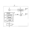
- FIG. 3 is a block diagram of the radar module 10 mounted on the automobile 1. As shown in FIG. 3, the radar module 10 includes a signal source 11, a transmission unit 12, a transmission antenna 13, a reception antenna 14, a reception unit 15, a signal processing unit 16, an external interface 17, and the like.
- a one-chip IC in which a signal source 11, a transmission unit 12, a reception unit 15, a signal processing unit 16, and an I / O port (not shown) are arranged on a single substrate can be applied.
- the transmission antenna 13 and the reception antenna 14 are configured by, for example, a copper foil pattern formed on a printed circuit board.
- a one-chip IC having a signal source 11 and the like, an IC external component, an external interface 17 and the like are mounted on a printed circuit board having a transmission antenna 13 and a reception antenna 14.
- the radar module 10 is configured by covering the printed circuit board with a shield case.
- the signal source 11 generates a transmission signal subjected to frequency modulation (FM) by adding a triangular wave modulation signal to a control voltage of a voltage controlled oscillator (VCO).
- the transmission unit 12 includes, for example, a directional coupler that outputs a transmission signal to the transmission antenna 13 and distributes a part of the transmission signal to the reception unit 15.
- the transmission antenna 13 radiates a transmission signal around the automobile 1 as a transmission wave. When the transmitted wave reaches the target object, it reflects according to the reflectance of the target object.
- the receiving antenna 14 receives a reflected signal generated by being reflected by the target object and outputs it to the receiving unit 15.
- the receiving unit 15 includes, for example, a mixer that generates a beat signal (received signal) by mixing the reflected signal output from the receiving antenna 14 and the transmission signal output from the transmitting unit 12 (directional coupler). .
- the receiving unit 15 outputs the generated beat signal to the signal processing unit 16.
- the signal processing unit 16 includes a frequency analysis unit 161, an object detection unit 162, and a person determination unit 163.
- the frequency analysis unit 161 performs frequency analysis by performing processing such as Fast Fourier Transform (FFT) on the beat signal digitized by the AD converter (not shown).
- the object detection unit 162 detects the target object based on the frequency distribution (beat frequency peak) of the beat signal calculated by the frequency analysis unit 161, and also detects the distance to the detected target object and the relative to the target object. Calculate the speed.
- the person determination unit 163 determines whether or not the detected target object is a person based on the received power of the beat signal in which the target object is detected. The object identification process in the person determination unit 163 will be described later.
- Information on the surrounding environment generated by the signal processing unit 16 is output to the safe driving support operation unit 20 via the external interface 17.
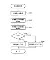
- FIG. 4 is a flowchart illustrating an example of object identification processing in the person determination unit 163.
- the object identification process shown in FIG. 4 is started when a new target object is detected by the object detection unit 162, for example.
- the beat signal input to the signal processing unit 16 is stored in a storage unit (not shown) for a predetermined period.
- step S101 the human determination section 163 acquires a plurality of received power P r of the beat signal target object has been detected. In order to obtain a stable distribution of the received power Pr, the number of acquired data is preferably 7 or more.
- step S102 the person determination unit 163 calculates an average value E of the received power Pr .
- step S103 the person determination unit 163 calculates a variance value V of the received power Pr .
- step S104 the person determination unit 163 compares the square of the average value E with the variance value V.
- the determination index E 2 / V obtained by dividing the square of the average value E by the variance value V is smaller than the first reference value S1
- the process proceeds to step S105. If the determination index E 2 / V is greater than or equal to the first reference value S1, the process proceeds to step S106.
- the “first reference value S1” is for identifying the target object by the determination index E 2 / V, and is set in the vicinity of 1.
- step S105 the person determination unit 163 determines that the detected target object is “person”.
- step S106 the person determination unit 163 determines that the detected target object is an “artificial object”.
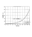
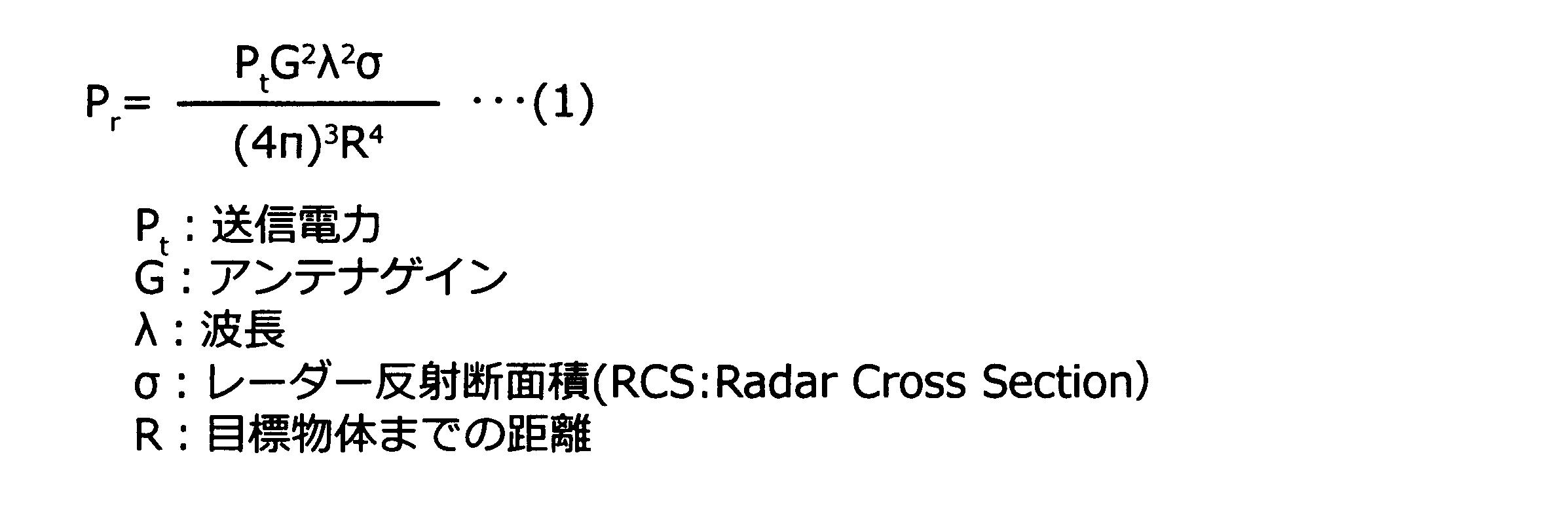
- the received power P r of the radar in free space is represented by the following formula (1).
- FIG. 6 is a histogram showing received power measurement results (distribution state) when the target object is a person and an artificial object (here, a reflector).
- FIG. 6 shows that the distribution of the measurement data of the reflector is close to the Rice distribution, and the distribution of the measurement data of the person is close to the Rayleigh distribution.
- the received power P r when the target object is a person may be considered to follow the exponential distribution.
- the RCS is considered to be a constant value.
- the variation of the received power P r varies depending on the SNR, 2 squared clearly greater than the variance value V of the average value E of the received power P r, the E 2 / V> 1 (see FIG. 5 ).
- the radar module 10 includes the transmission antenna 13, the reception antenna 14, the signal source 11 that generates the transmission signal, the transmission unit 12 that transmits the transmission signal toward the target object via the transmission antenna 13, A reception unit 15 that receives a reflection signal generated by reflecting a transmission signal from a target object via the reception antenna 14, and a signal processing unit 16 that performs signal processing based on a reception signal (beat signal) output from the reception unit 15. And an external interface 17 for outputting information obtained by the signal processing unit 16.
- the signal processing unit 16 (human determination unit 163) calculates the average value E of the received power P r of the received signal variance values V, using the variance V and the calculated average value E, identifies the target object .
- the signal processor 16 (human judgment unit 163) compares the square and variance value V of the average value E of the received power P r, divided by the square of the average value E at variance V When the determination index E 2 / V is smaller than the first reference value S1 set in the vicinity of 1, the target object is determined to be a person.
- the target object is identified using the average value E and the variance value V of the received power Pr of the received signal using the fact that the RCS of the person has an exponential distribution. However, it is possible to accurately identify whether the target object is a person.
- the identification result of the target object obtained by the person determination unit 163 of the radar module 10 is output to the safe driving support unit 20 as information on the surrounding environment together with the presence / absence of the target object, the distance to the target object, and the like.
- the safe driving support operation unit 20 performs a safe driving support operation for avoiding or reducing danger based on information about the surrounding environment.
- the safe driving support operation unit 20 includes a stop operation unit 21, a driving operation unit 22, and a warning unit 23.
- the stop operation unit 21 supports the stop operation of the automobile 1 based on information about the surrounding environment.
- the brake 212 operates under the control of the stop control unit 211 to automatically decelerate or stop the automobile 1. Thereby, danger can be avoided quickly.
- the driving operation unit 22 supports the driving operation of the automobile 1 based on information about the surrounding environment. Specifically, the handle 222 operates under the control of the driving control unit 221 to automatically change the traveling direction of the automobile 1. Thereby, danger can be avoided quickly.
- the warning unit 23 gives a warning to the passenger or the outside based on information on the surrounding environment. Specifically, the seat belt 232 is automatically rolled up under the control of the warning control unit 231 to give a stimulus to the passenger. The passenger can perceive a danger by perceiving a tactile change caused by the seat belt 232.
- the seat 233 vibrates under the control of the warning control unit 231 and gives a stimulus to the passenger.
- the passenger can perceive the danger by perceiving the tactile change caused by the seat 233.
- the display unit 234 gives a warning by display under the control of the warning control unit 231.
- a liquid crystal display such as a car navigation system, a windshield, glasses or a head-up display worn by a passenger, a back monitor, or the like can be applied.
- the display unit 234 displays the direction in which the person is present on the display unit 234 in 2D, or changes the display color (background color, etc.) of the display unit 234 according to the distance to the person (safety: blue ⁇ yellow ⁇ Red: Danger) to warn the passenger.
- the passenger can detect the danger visually.
- the voice output unit (speaker) 235 gives a warning by voice.
- the passenger can detect danger by hearing.
- the wireless communication unit 236 transmits warning information to a portable terminal (for example, a smartphone) possessed by a passenger or a pedestrian.
- a portable terminal for example, a smartphone
- a warning is given by display or sound.
- a passenger or a pedestrian can detect the danger from the transmission information from the portable terminal that he / she owns.
- the odor generating unit 237 generates odor.
- the passenger can detect the danger by smell.
- the headlight irradiation mode may be changed according to the distance to the target object and the direction in which the target object is located.
- the safe driving support operation unit 20 performs the above-described operation based on information related to the surrounding environment, so that not only the safety of the own vehicle but also the safety of other vehicles and pedestrians are significantly improved. .
- the present invention is not limited to the above embodiment, and can be changed without departing from the gist thereof.
- a determination indicator for determining that the target object is a person it is also possible to use a value obtained by subtracting the variance V from the square of the average value E of the received power P r (E 2 -V). In this case, when the determination index (E 2 ⁇ V) is smaller than the second reference value set in the vicinity of 0, it is determined that the target object is a person.
- the radar module 10 may be applied with a method other than the FMCW method, such as a pulse method or FSK (Frequency Shift Keying). Further, the radar module according to the present invention can be mounted not only on automobiles but also on transportation equipment such as railway vehicles, ships, airplanes, etc., or roadside devices installed on roads.
- the transport device may be mounted with a combination of other radar modules (for example, 76 GHz millimeter wave radar) and sensors such as a stereo camera. By installing multiple sensors, it is possible to more accurately grasp the surrounding environment of transportation equipment.
Abstract
Description
受信アンテナと、
送信信号を生成する信号源と、
前記送信アンテナを介して前記送信信号を目標物体に向けて送信する送信部と、
前記送信信号が目標物体で反射して生じる反射信号を前記受信アンテナを介して受信する受信部と、
前記受信部から出力される受信信号に基づいて信号処理を行う信号処理部と、
前記信号処理部で得られた情報を出力する外部インターフェースと、を備え、
前記信号処理部は、前記受信信号の受信電力の平均値と分散値を算出し、算出された平均値と分散値を用いて、前記目標物体を識別することを特徴とする。
前記レーダーモジュールから出力された情報に基づいて、危険を回避又は軽減するための動作を行う安全運転支援動作部と、を備えることを特徴とする。
前記反射信号に基づく受信電力を取得する第1ステップと、
前記受信電力の平均値を算出する第2ステップと、
前記受信電力の分散値を算出する第3ステップと、
前記平均値と前記分散値を用いて前記目標物体を識別する第4ステップと、を備えることを特徴とする。
送信部12は、例えば送信信号を送信アンテナ13に出力するとともに、送信信号の一部を受信部15に分配する方向性結合器を含む。
送信アンテナ13は、送信信号を自動車1の周囲に送信波として放射する。送信波は目標物体に到達すると、目標物体の反射率に応じて反射する。
受信部15は、例えば受信アンテナ14から出力された反射信号と、送信部12(方向性結合器)から出力された送信信号とを混合して、ビート信号(受信信号)を生成するミキサーを含む。受信部15は、生成したビート信号を信号処理部16に出力する。
周波数解析部161は、AD変換器(図示略)でデジタル化されたビート信号に対して高速フーリエ変換(FFT:Fast Fourier Transform)等の処理を実行して、周波数解析を行う。
物体検知部162は、周波数解析部161で算出されたビート信号の周波数分布(ビート周波数のピーク)に基づいて、目標物体を検知するとともに、検知された目標物体までの距離及び目標物体との相対速度を算出する。
人判定部163は、目標物体が検知されたビート信号の受信電力に基づいて、検知された目標物体が人であるか否かを判定する。人判定部163における物体識別処理については後述する。
信号処理部16で生成された周囲環境に関する情報は、外部インターフェース17を介して安全運転支援動作部20に出力される。
ステップS102において、人判定部163は、受信電力Prの平均値Eを算出する。
ステップS103において、人判定部163は、受信電力Prの分散値Vを算出する。
ステップS106において、人判定部163は、検知された目標物体は「人工物」であると判定する。
具体的には、信号処理部16(人判定部163)は、受信電力Prの平均値Eの2乗と分散値Vを比較して、平均値Eの2乗を分散値Vで除算した判定指標E2/Vが1近傍に設定される第1の基準値S1よりも小さい場合に、目標物体が人であると判定する。
停止動作部21は、周囲環境に関する情報に基づいて、自動車1の停止動作を支援する。具体的には、停止制御部211の制御下で、ブレーキ212が動作し、自動車1を自動的に減速又は停止させる。これにより、速やかに危険を回避することができる。
表示部234は、例えば人がいる方向を表示部234に2D表示したり、人までの距離に応じて表示部234の表示色(背景色など)を変更したりする(安全:青→黄→赤:危険)ことにより、搭乗者に対して警告を行う。搭乗者は、視覚によって危険を察知することができる。
例えば、目標物体が人であると判定するための判定指標として、受信電力Prの平均値Eの2乗から分散値Vを減算した値(E2-V)を用いることもできる。この場合、判定指標(E2-V)が0近傍に設定される第2の基準値より小さい場合に、目標物体が人であると判定される。
ただし、目標物体が人である場合の判定指標(E2-V)と目標物体が人工物である場合の判定指標(E2-V)の乖離幅は、E2/Vを判定指標とした場合よりも小さく、適切な第2の基準値の設定が難しくなるので、判定指標としてはE2/Vを用いることが好ましい。
また、本発明に係るレーダーモジュールは、自動車の他、鉄道車両、船舶、飛行機等の輸送機器、又は道路に設置される路側機に搭載することができる。輸送機器には、その他のレーダーモジュール(例えば76GHzミリ波レーダー)やステレオカメラ等のセンサーを組み合わせて搭載してもよい。複数のセンサーを搭載することにより、輸送機器の周囲環境をさらに的確に把握することができる。
10 レーダーモジュール
11 信号源
12 送信部
13 送信アンテナ
14 受信アンテナ
15 受信部
16 信号処理部
17 外部インターフェース
20 安全運転支援動作部
161 周波数解析部
162 物体検知部
163 人判定部
Claims (19)
- 送信アンテナと、
受信アンテナと、
送信信号を生成する信号源と、
前記送信アンテナを介して前記送信信号を目標物体に向けて送信する送信部と、
前記送信信号が目標物体で反射して生じる反射信号を前記受信アンテナを介して受信する受信部と、
前記受信部から出力される受信信号に基づいて信号処理を行う信号処理部と、
前記信号処理部で得られた情報を出力する外部インターフェースと、を備え、
前記信号処理部は、前記受信信号の受信電力の平均値と分散値を算出し、算出された平均値と分散値を用いて、前記目標物体を識別することを特徴とするレーダーモジュール。 - 前記信号処理部は、前記平均値の2乗と前記分散値を比較して、前記目標物体を識別することを特徴とする請求項1に記載のレーダーモジュール。
- 前記信号処理部は、前記平均値の2乗を前記分散値で除算した判定指標が1近傍に設定される第1の基準値より小さい場合に、前記目標物体が人であると判定することを特徴とする請求項2に記載のレーダーモジュール。
- 前記信号処理部は、前記平均値の2乗から前記分散値を減算した判定指標が0近傍に設定される第2の基準値より小さい場合に、前記目標物体が人であると判定することを特徴とする請求項2に記載のレーダーモジュール。
- 前記信号源、前記送信部、前記受信部、及び前記信号処理部が一枚の基板上に配置されたワンチップICを有することを特徴とする請求項1に記載のレーダーモジュール。
- 前記送信アンテナ及び前記受信アンテナが形成されたプリント回路基板上に前記ワンチップIC及び前記外部インターフェースが実装され、当該プリント回路基板がシールドケースで覆われていることを特徴とする請求項5に記載のレーダーモジュール。
- 請求項1に記載のレーダーモジュールと、
前記レーダーモジュールから出力された情報に基づいて、危険を回避又は軽減するための動作を行う安全運転支援動作部と、を備えることを特徴とする輸送機器。 - 前記安全運転支援動作部は、前記レーダーモジュールから出力された情報に基づいて、当該輸送機器の停止動作を支援する停止動作部を有することを特徴とする請求項7に記載の輸送機器。
- 前記安全運転支援動作部は、前記レーダーモジュールから出力された情報に基づいて、当該輸送機器の運転動作を支援する運転動作部を有することを特徴とする請求項7に記載の輸送機器。
- 前記安全運転支援動作部は、前記レーダーモジュールから出力された情報に基づいて、搭乗者又は外部に対して警告を行う警告部を有することを特徴とする請求項7に記載の輸送機器。
- 前記警告部は、表示によって警告を行う表示部を有することを特徴とする請求項10に記載の輸送機器。
- 前記警告部は、音声によって警告を行う音声出力部を有することを特徴とする請求項10に記載の輸送機器。
- 前記警告部は、臭気を発することによって警告を行う臭気発生部を有することを特徴とする請求項10に記載の輸送機器。
- 前記警告部は、搭乗者に触覚変化をもたらすことによって警告を行う刺激発生部を有することを特徴とする請求項10に記載の輸送機器。
- 前記警告部は、警告を示す情報を無線で送信する無線通信部を有することを特徴とする請求項10に記載の輸送機器。
- 所定の送信信号を送信し、前記送信信号が目標物体で反射して生じる反射信号を受信するレーダー装置における物体識別方法であって、
前記反射信号に基づく受信電力を取得する第1ステップと、
前記受信電力の平均値を算出する第2ステップと、
前記受信電力の分散値を算出する第3ステップと、
前記平均値と前記分散値を用いて前記目標物体を識別する第4ステップと、を備えることを特徴とする物体識別方法。 - 前記第4ステップにおいて、前記平均値の2乗と前記分散値を比較して、前記目標物体を識別することを特徴とする請求項16に記載の物体識別方法。
- 前記第4ステップにおいて、前記平均値の2乗を前記分散値で除算した判定指標が1である場合に、前記目標物体が人であると判定することを特徴とする請求項17に記載の物体識別方法。
- 前記第4ステップにおいて、前記平均値の2乗から前記分散値を減算した判定指標が0である場合に、前記目標物体が人であると判定することを特徴とする請求項17に記載の物体識別方法。
Priority Applications (4)
| Application Number | Priority Date | Filing Date | Title |
|---|---|---|---|
| US15/300,379 US10371815B2 (en) | 2014-03-31 | 2015-03-31 | Radar module, transport apparatus, and object detection method |
| CN201580018255.3A CN106164698B (zh) | 2014-03-31 | 2015-03-31 | 雷达模块、输送设备以及物体识别方法 |
| EP15773021.9A EP3128339B1 (en) | 2014-03-31 | 2015-03-31 | Radar module, transport equipment, and object identification method |
| JP2016511387A JP6540689B2 (ja) | 2014-03-31 | 2015-03-31 | レーダーモジュール、輸送機器、及び物体識別方法 |
Applications Claiming Priority (2)
| Application Number | Priority Date | Filing Date | Title |
|---|---|---|---|
| JP2014072291 | 2014-03-31 | ||
| JP2014-072291 | 2014-03-31 |
Publications (1)
| Publication Number | Publication Date |
|---|---|
| WO2015151507A1 true WO2015151507A1 (ja) | 2015-10-08 |
Family
ID=54239852
Family Applications (1)
| Application Number | Title | Priority Date | Filing Date |
|---|---|---|---|
| PCT/JP2015/001847 WO2015151507A1 (ja) | 2014-03-31 | 2015-03-31 | レーダーモジュール、輸送機器、及び物体識別方法 |
Country Status (5)
| Country | Link |
|---|---|
| US (1) | US10371815B2 (ja) |
| EP (1) | EP3128339B1 (ja) |
| JP (1) | JP6540689B2 (ja) |
| CN (1) | CN106164698B (ja) |
| WO (1) | WO2015151507A1 (ja) |
Cited By (3)
| Publication number | Priority date | Publication date | Assignee | Title |
|---|---|---|---|---|
| KR20190051460A (ko) * | 2017-11-07 | 2019-05-15 | 현대모비스 주식회사 | 차량용 물체 식별 장치 및 방법 |
| JP2019219252A (ja) * | 2018-06-19 | 2019-12-26 | マツダ株式会社 | 車両用物標検出方法および装置 |
| US11226408B2 (en) | 2018-07-03 | 2022-01-18 | Panasonic Intellectual Property Management Co., Ltd. | Sensor, estimating device, estimating method, and recording medium |
Families Citing this family (9)
| Publication number | Priority date | Publication date | Assignee | Title |
|---|---|---|---|---|
| JP6765100B2 (ja) * | 2016-08-31 | 2020-10-07 | 学校法人早稲田大学 | 視野外障害物検知システム |
| US10912493B2 (en) * | 2017-01-06 | 2021-02-09 | Panasonic Intellectual Property Management Co., Ltd. | Sensor and method |
| JP6734831B2 (ja) * | 2017-10-04 | 2020-08-05 | 矢崎総業株式会社 | 検出機器及び検出システム |
| US10775482B2 (en) * | 2018-04-11 | 2020-09-15 | Infineon Technologies Ag | Human detection and identification in a setting using millimeter-wave radar |
| US11183772B2 (en) | 2018-09-13 | 2021-11-23 | Infineon Technologies Ag | Embedded downlight and radar system |
| JP7192600B2 (ja) * | 2019-03-20 | 2022-12-20 | 株式会社デンソー | 警報装置 |
| CN110040589B (zh) * | 2019-04-19 | 2022-05-24 | 日立楼宇技术(广州)有限公司 | 一种空间拥挤度的检测方法及电梯轿厢的调度方法 |
| CN113141382A (zh) * | 2020-01-17 | 2021-07-20 | 北京小米移动软件有限公司 | 数据发送方法、数据接收方法、数据传输方法及移动终端 |
| CN112596111B (zh) * | 2020-11-04 | 2024-02-13 | 普联技术有限公司 | 障碍物识别方法、装置、设备及可读存储介质 |
Citations (6)
| Publication number | Priority date | Publication date | Assignee | Title |
|---|---|---|---|---|
| JP2005284799A (ja) * | 2004-03-30 | 2005-10-13 | Honda Motor Co Ltd | 歩行者検出装置 |
| JP2006500664A (ja) * | 2002-09-23 | 2006-01-05 | ローベルト ボツシユ ゲゼルシヤフト ミツト ベシユレンクテル ハフツング | 車両の衝突を阻止する方法および装置 |
| JP2007512989A (ja) * | 2003-05-16 | 2007-05-24 | ダイムラークライスラー・アクチェンゲゼルシャフト | 自動車内における運転者の負荷を調整するための方法及び装置 |
| JP2007271559A (ja) * | 2006-03-31 | 2007-10-18 | Secom Co Ltd | 移動物体検知装置 |
| JP2008219284A (ja) * | 2007-03-01 | 2008-09-18 | Fujitsu Component Ltd | 送受信装置 |
| JP2012243049A (ja) * | 2011-05-19 | 2012-12-10 | Fuji Heavy Ind Ltd | 環境認識装置および環境認識方法 |
Family Cites Families (18)
| Publication number | Priority date | Publication date | Assignee | Title |
|---|---|---|---|---|
| US4489319A (en) * | 1981-03-06 | 1984-12-18 | Raytheon Company | Detector with variance sensitivity |
| US4972193A (en) * | 1988-08-09 | 1990-11-20 | The General Electric Company, P.L.C. | Target recognition |
| FR2653563B1 (fr) * | 1989-10-24 | 1992-01-10 | Aerospatiale | Procede et dispositif pour la reconnaissance d'une cible. |
| US5392050A (en) * | 1993-08-12 | 1995-02-21 | Grumman Aerospace Corporation | Method of recognizing a radar target object type and apparatus therefor |
| US5867118A (en) * | 1995-06-07 | 1999-02-02 | Lockheed Martin Corporation | Apparatus for and method of classifying patterns |
| SE511061C2 (sv) * | 1997-11-21 | 1999-07-26 | Celsiustech Electronics Ab | Förfarande för klassificering av upphöjda objekt |
| US6337654B1 (en) * | 1999-11-05 | 2002-01-08 | Lockheed Martin Corporation | A-scan ISAR classification system and method therefor |
| JP4016826B2 (ja) * | 2002-12-10 | 2007-12-05 | 株式会社デンソー | 物標識別方法及び装置、プログラム |
| EP1640741A1 (en) * | 2004-09-23 | 2006-03-29 | Mitsubishi Electric Information Technology Centre Europe B.V. | Radar target classification using statistical descriptors |
| US20070253625A1 (en) * | 2006-04-28 | 2007-11-01 | Bbnt Solutions Llc | Method for building robust algorithms that classify objects using high-resolution radar signals |
| US8055445B2 (en) * | 2008-09-24 | 2011-11-08 | Delphi Technologies, Inc. | Probabilistic lane assignment method |
| US20100321234A1 (en) * | 2009-06-19 | 2010-12-23 | U.S. Government As Represented By The Secretary Of The Army | Computationally efficent radar processing method and sytem for sar and gmti on a slow moving platform |
| CN101975951B (zh) * | 2010-06-09 | 2013-03-20 | 北京理工大学 | 一种融合距离和图像信息的野外环境障碍检测方法 |
| JP5861396B2 (ja) | 2011-11-02 | 2016-02-16 | トヨタ自動車株式会社 | 車両用歩行者検知装置、車両用歩行者保護システム |
| JP6003079B2 (ja) | 2012-02-16 | 2016-10-05 | 富士通株式会社 | 信号機制御システム、信号機制御方法、及びプログラム |
| CN103207395B (zh) * | 2013-03-26 | 2014-10-08 | 南京理工大学 | 一种汽车主动防撞雷达装置 |
| CN203310994U (zh) * | 2013-07-05 | 2013-11-27 | 黄淮学院 | 毫米波汽车防撞雷达装置 |
| CN103439696B (zh) * | 2013-10-11 | 2015-06-17 | 西安电子科技大学 | 低信噪比条件下的地面运动目标稳健识别方法 |
-
2015
- 2015-03-31 JP JP2016511387A patent/JP6540689B2/ja active Active
- 2015-03-31 US US15/300,379 patent/US10371815B2/en active Active
- 2015-03-31 WO PCT/JP2015/001847 patent/WO2015151507A1/ja active Application Filing
- 2015-03-31 EP EP15773021.9A patent/EP3128339B1/en active Active
- 2015-03-31 CN CN201580018255.3A patent/CN106164698B/zh active Active
Patent Citations (6)
| Publication number | Priority date | Publication date | Assignee | Title |
|---|---|---|---|---|
| JP2006500664A (ja) * | 2002-09-23 | 2006-01-05 | ローベルト ボツシユ ゲゼルシヤフト ミツト ベシユレンクテル ハフツング | 車両の衝突を阻止する方法および装置 |
| JP2007512989A (ja) * | 2003-05-16 | 2007-05-24 | ダイムラークライスラー・アクチェンゲゼルシャフト | 自動車内における運転者の負荷を調整するための方法及び装置 |
| JP2005284799A (ja) * | 2004-03-30 | 2005-10-13 | Honda Motor Co Ltd | 歩行者検出装置 |
| JP2007271559A (ja) * | 2006-03-31 | 2007-10-18 | Secom Co Ltd | 移動物体検知装置 |
| JP2008219284A (ja) * | 2007-03-01 | 2008-09-18 | Fujitsu Component Ltd | 送受信装置 |
| JP2012243049A (ja) * | 2011-05-19 | 2012-12-10 | Fuji Heavy Ind Ltd | 環境認識装置および環境認識方法 |
Non-Patent Citations (1)
| Title |
|---|
| See also references of EP3128339A4 * |
Cited By (5)
| Publication number | Priority date | Publication date | Assignee | Title |
|---|---|---|---|---|
| KR20190051460A (ko) * | 2017-11-07 | 2019-05-15 | 현대모비스 주식회사 | 차량용 물체 식별 장치 및 방법 |
| KR102285959B1 (ko) | 2017-11-07 | 2021-08-05 | 현대모비스 주식회사 | 차량용 물체 식별 장치 및 방법 |
| JP2019219252A (ja) * | 2018-06-19 | 2019-12-26 | マツダ株式会社 | 車両用物標検出方法および装置 |
| JP7119627B2 (ja) | 2018-06-19 | 2022-08-17 | マツダ株式会社 | 車両用物標検出方法および装置 |
| US11226408B2 (en) | 2018-07-03 | 2022-01-18 | Panasonic Intellectual Property Management Co., Ltd. | Sensor, estimating device, estimating method, and recording medium |
Also Published As
| Publication number | Publication date |
|---|---|
| US20170139043A1 (en) | 2017-05-18 |
| JP6540689B2 (ja) | 2019-07-10 |
| EP3128339B1 (en) | 2020-10-21 |
| EP3128339A1 (en) | 2017-02-08 |
| US10371815B2 (en) | 2019-08-06 |
| CN106164698A (zh) | 2016-11-23 |
| CN106164698B (zh) | 2019-11-26 |
| EP3128339A4 (en) | 2018-01-10 |
| JPWO2015151507A1 (ja) | 2017-04-13 |
Similar Documents
| Publication | Publication Date | Title |
|---|---|---|
| WO2015151507A1 (ja) | レーダーモジュール、輸送機器、及び物体識別方法 | |
| US8548643B2 (en) | Information providing device for vehicle | |
| KR20200102004A (ko) | 충돌 방지 장치, 시스템 및 방법 | |
| US10192443B2 (en) | Collision avoidance system and collision avoidance method | |
| EP1806596A1 (en) | Method and system for generating a target alert | |
| US9908469B2 (en) | Driving support device | |
| KR20150029471A (ko) | 차량의 추월 위험 경고 장치 및 방법 | |
| CN103909926A (zh) | 车辆侧向防碰撞方法、设备以及系统 | |
| JP5482670B2 (ja) | 物体検出装置 | |
| WO2015009221A1 (en) | Method and sensor for transferring information between vehicles | |
| JP2013114421A (ja) | 車両用制御装置、特定物体判別装置、特定物体判別方法、特定物体判別プログラム | |
| JP3036268B2 (ja) | 車載用安全運転支援装置 | |
| JP6989766B2 (ja) | レーダー装置及び物標検出方法 | |
| JP5659587B2 (ja) | レーダ装置、路側器及び車載装置 | |
| CN210617998U (zh) | 一种用于货运和客运车辆的盲区检测设备 | |
| WO2020084805A1 (ja) | 報知装置及び報知方法 | |
| RU2676854C2 (ru) | Способ предупреждения столкновения транспортных средств | |
| JP4429436B2 (ja) | 交通制御システム | |
| KR100669902B1 (ko) | 지피에스를 이용하는 차량충돌방지를 위한차량안전운행정보 서비스 시스템 및 그 방법 | |
| WO2019065442A1 (ja) | レーダー装置及び物標検出方法 | |
| EP4202490A1 (en) | Radar signaling for emergency scenarios | |
| WO2023047616A1 (ja) | 自車死角監視システム、および、自車死角監視方法 | |
| JPH06160518A (ja) | 車載用レーダ装置 | |
| KR20230143245A (ko) | 차량 우회전 안전 확보 시스템 및 방법 | |
| CN115440082A (zh) | 一种行车安全预警方法 |
Legal Events
| Date | Code | Title | Description |
|---|---|---|---|
| 121 | Ep: the epo has been informed by wipo that ep was designated in this application |
Ref document number: 15773021 Country of ref document: EP Kind code of ref document: A1 |
|
| ENP | Entry into the national phase |
Ref document number: 2016511387 Country of ref document: JP Kind code of ref document: A |
|
| REEP | Request for entry into the european phase |
Ref document number: 2015773021 Country of ref document: EP |
|
| WWE | Wipo information: entry into national phase |
Ref document number: 15300379 Country of ref document: US Ref document number: 2015773021 Country of ref document: EP |
|
| NENP | Non-entry into the national phase |
Ref country code: DE |