WO2015151386A1 - 撮像装置、画像データの出力方法及びプログラム - Google Patents
撮像装置、画像データの出力方法及びプログラム Download PDFInfo
- Publication number
- WO2015151386A1 WO2015151386A1 PCT/JP2015/000678 JP2015000678W WO2015151386A1 WO 2015151386 A1 WO2015151386 A1 WO 2015151386A1 JP 2015000678 W JP2015000678 W JP 2015000678W WO 2015151386 A1 WO2015151386 A1 WO 2015151386A1
- Authority
- WO
- WIPO (PCT)
- Prior art keywords
- transmittance
- image data
- image
- imaging
- frame
- Prior art date
Links
Images
Classifications
-
- H—ELECTRICITY
- H04—ELECTRIC COMMUNICATION TECHNIQUE
- H04N—PICTORIAL COMMUNICATION, e.g. TELEVISION
- H04N23/00—Cameras or camera modules comprising electronic image sensors; Control thereof
- H04N23/70—Circuitry for compensating brightness variation in the scene
- H04N23/72—Combination of two or more compensation controls
-
- G—PHYSICS
- G03—PHOTOGRAPHY; CINEMATOGRAPHY; ANALOGOUS TECHNIQUES USING WAVES OTHER THAN OPTICAL WAVES; ELECTROGRAPHY; HOLOGRAPHY
- G03B—APPARATUS OR ARRANGEMENTS FOR TAKING PHOTOGRAPHS OR FOR PROJECTING OR VIEWING THEM; APPARATUS OR ARRANGEMENTS EMPLOYING ANALOGOUS TECHNIQUES USING WAVES OTHER THAN OPTICAL WAVES; ACCESSORIES THEREFOR
- G03B7/00—Control of exposure by setting shutters, diaphragms or filters, separately or conjointly
- G03B7/08—Control effected solely on the basis of the response, to the intensity of the light received by the camera, of a built-in light-sensitive device
-
- G—PHYSICS
- G02—OPTICS
- G02F—OPTICAL DEVICES OR ARRANGEMENTS FOR THE CONTROL OF LIGHT BY MODIFICATION OF THE OPTICAL PROPERTIES OF THE MEDIA OF THE ELEMENTS INVOLVED THEREIN; NON-LINEAR OPTICS; FREQUENCY-CHANGING OF LIGHT; OPTICAL LOGIC ELEMENTS; OPTICAL ANALOGUE/DIGITAL CONVERTERS
- G02F1/00—Devices or arrangements for the control of the intensity, colour, phase, polarisation or direction of light arriving from an independent light source, e.g. switching, gating or modulating; Non-linear optics
- G02F1/01—Devices or arrangements for the control of the intensity, colour, phase, polarisation or direction of light arriving from an independent light source, e.g. switching, gating or modulating; Non-linear optics for the control of the intensity, phase, polarisation or colour
- G02F1/13—Devices or arrangements for the control of the intensity, colour, phase, polarisation or direction of light arriving from an independent light source, e.g. switching, gating or modulating; Non-linear optics for the control of the intensity, phase, polarisation or colour based on liquid crystals, e.g. single liquid crystal display cells
- G02F1/133—Constructional arrangements; Operation of liquid crystal cells; Circuit arrangements
- G02F1/13306—Circuit arrangements or driving methods for the control of single liquid crystal cells
- G02F1/13318—Circuits comprising a photodetector
-
- G—PHYSICS
- G03—PHOTOGRAPHY; CINEMATOGRAPHY; ANALOGOUS TECHNIQUES USING WAVES OTHER THAN OPTICAL WAVES; ELECTROGRAPHY; HOLOGRAPHY
- G03B—APPARATUS OR ARRANGEMENTS FOR TAKING PHOTOGRAPHS OR FOR PROJECTING OR VIEWING THEM; APPARATUS OR ARRANGEMENTS EMPLOYING ANALOGOUS TECHNIQUES USING WAVES OTHER THAN OPTICAL WAVES; ACCESSORIES THEREFOR
- G03B11/00—Filters or other obturators specially adapted for photographic purposes
-
- G—PHYSICS
- G06—COMPUTING; CALCULATING OR COUNTING
- G06T—IMAGE DATA PROCESSING OR GENERATION, IN GENERAL
- G06T11/00—2D [Two Dimensional] image generation
- G06T11/60—Editing figures and text; Combining figures or text
-
- H—ELECTRICITY
- H04—ELECTRIC COMMUNICATION TECHNIQUE
- H04N—PICTORIAL COMMUNICATION, e.g. TELEVISION
- H04N23/00—Cameras or camera modules comprising electronic image sensors; Control thereof
- H04N23/50—Constructional details
- H04N23/55—Optical parts specially adapted for electronic image sensors; Mounting thereof
-
- H—ELECTRICITY
- H04—ELECTRIC COMMUNICATION TECHNIQUE
- H04N—PICTORIAL COMMUNICATION, e.g. TELEVISION
- H04N23/00—Cameras or camera modules comprising electronic image sensors; Control thereof
- H04N23/60—Control of cameras or camera modules
- H04N23/62—Control of parameters via user interfaces
-
- H—ELECTRICITY
- H04—ELECTRIC COMMUNICATION TECHNIQUE
- H04N—PICTORIAL COMMUNICATION, e.g. TELEVISION
- H04N23/00—Cameras or camera modules comprising electronic image sensors; Control thereof
- H04N23/60—Control of cameras or camera modules
- H04N23/667—Camera operation mode switching, e.g. between still and video, sport and normal or high- and low-resolution modes
-
- H—ELECTRICITY
- H04—ELECTRIC COMMUNICATION TECHNIQUE
- H04N—PICTORIAL COMMUNICATION, e.g. TELEVISION
- H04N23/00—Cameras or camera modules comprising electronic image sensors; Control thereof
- H04N23/70—Circuitry for compensating brightness variation in the scene
-
- H—ELECTRICITY
- H04—ELECTRIC COMMUNICATION TECHNIQUE
- H04N—PICTORIAL COMMUNICATION, e.g. TELEVISION
- H04N23/00—Cameras or camera modules comprising electronic image sensors; Control thereof
- H04N23/70—Circuitry for compensating brightness variation in the scene
- H04N23/73—Circuitry for compensating brightness variation in the scene by influencing the exposure time
-
- H—ELECTRICITY
- H04—ELECTRIC COMMUNICATION TECHNIQUE
- H04N—PICTORIAL COMMUNICATION, e.g. TELEVISION
- H04N23/00—Cameras or camera modules comprising electronic image sensors; Control thereof
- H04N23/70—Circuitry for compensating brightness variation in the scene
- H04N23/741—Circuitry for compensating brightness variation in the scene by increasing the dynamic range of the image compared to the dynamic range of the electronic image sensors
-
- H—ELECTRICITY
- H04—ELECTRIC COMMUNICATION TECHNIQUE
- H04N—PICTORIAL COMMUNICATION, e.g. TELEVISION
- H04N23/00—Cameras or camera modules comprising electronic image sensors; Control thereof
- H04N23/70—Circuitry for compensating brightness variation in the scene
- H04N23/743—Bracketing, i.e. taking a series of images with varying exposure conditions
-
- H—ELECTRICITY
- H04—ELECTRIC COMMUNICATION TECHNIQUE
- H04N—PICTORIAL COMMUNICATION, e.g. TELEVISION
- H04N25/00—Circuitry of solid-state image sensors [SSIS]; Control thereof
- H04N25/50—Control of the SSIS exposure
- H04N25/57—Control of the dynamic range
- H04N25/58—Control of the dynamic range involving two or more exposures
- H04N25/587—Control of the dynamic range involving two or more exposures acquired sequentially, e.g. using the combination of odd and even image fields
-
- G—PHYSICS
- G06—COMPUTING; CALCULATING OR COUNTING
- G06T—IMAGE DATA PROCESSING OR GENERATION, IN GENERAL
- G06T2207/00—Indexing scheme for image analysis or image enhancement
- G06T2207/20—Special algorithmic details
- G06T2207/20212—Image combination
- G06T2207/20221—Image fusion; Image merging
-
- H—ELECTRICITY
- H04—ELECTRIC COMMUNICATION TECHNIQUE
- H04N—PICTORIAL COMMUNICATION, e.g. TELEVISION
- H04N23/00—Cameras or camera modules comprising electronic image sensors; Control thereof
- H04N23/60—Control of cameras or camera modules
- H04N23/63—Control of cameras or camera modules by using electronic viewfinders
- H04N23/631—Graphical user interfaces [GUI] specially adapted for controlling image capture or setting capture parameters
- H04N23/632—Graphical user interfaces [GUI] specially adapted for controlling image capture or setting capture parameters for displaying or modifying preview images prior to image capturing, e.g. variety of image resolutions or capturing parameters
-
- H—ELECTRICITY
- H04—ELECTRIC COMMUNICATION TECHNIQUE
- H04N—PICTORIAL COMMUNICATION, e.g. TELEVISION
- H04N23/00—Cameras or camera modules comprising electronic image sensors; Control thereof
- H04N23/60—Control of cameras or camera modules
- H04N23/695—Control of camera direction for changing a field of view, e.g. pan, tilt or based on tracking of objects
-
- H—ELECTRICITY
- H04—ELECTRIC COMMUNICATION TECHNIQUE
- H04N—PICTORIAL COMMUNICATION, e.g. TELEVISION
- H04N25/00—Circuitry of solid-state image sensors [SSIS]; Control thereof
- H04N25/70—SSIS architectures; Circuits associated therewith
- H04N25/71—Charge-coupled device [CCD] sensors; Charge-transfer registers specially adapted for CCD sensors
- H04N25/75—Circuitry for providing, modifying or processing image signals from the pixel array
Definitions
- This technology relates to a technology such as an imaging device that performs imaging with an imaging device.
- analog image data acquired by the imaging element is output to an analog signal processing unit.
- the analog image data output to the analog signal processing unit is subjected to analog signal processing (amplification or the like), and then output to the A / D conversion unit to be converted into digital image data.
- This digital image data is output to the digital signal processing unit, and noise removal processing, white balance processing, color correction processing, edge enhancement processing, gamma correction processing, and the like are performed in the digital signal processing unit.
- the digital image data subjected to these processes is output from the digital signal processing unit, and the image data is displayed on the liquid crystal panel and stored in the recording device.
- a method of adjusting the exposure amount in the digital signal processing unit may be used.
- image data that is too bright at the time of A / D conversion by the A / D conversion unit may lose some of the gradation during A / D conversion. For this reason, there is a problem that the digital signal processing unit cannot restore a portion that has been damaged at the time of A / D conversion.
- a method of adjusting the electronic shutter (adjusting the exposure time in the image sensor), a method of adjusting the aperture of the diaphragm, or the like is used.
- JP 2012-104994 A (see paragraphs [0038] and [0055] FIG. 3)
- the method of adjusting the electronic shutter has a problem that the dynamic resolution is disturbed and the image quality of the image data is deteriorated.
- the method of adjusting the aperture opening has problems such as aperture blurring and subject depth fluctuation.
- the image data output from the image sensor cannot be output as image data with an appropriate exposure amount.
- an object of the present technology is to provide a technology such as an imaging device that can output image data output from an imaging device as image data with an appropriate exposure amount.
- the imaging device includes a transmittance adjustment unit, an imaging element, and a control unit.
- the transmittance adjusting unit can adjust the light transmittance according to the applied voltage.
- the imaging device performs imaging by exposing light transmitted through the transmittance adjusting unit.
- the control unit obtains first image data by setting the transmittance of the transmittance adjusting unit to a first transmittance and causing the image sensor to perform imaging, and based on the first image data
- the second transmittance is calculated in order to cause the imaging device to capture an image with an appropriate exposure amount, and the transmittance of the transmittance adjusting unit is set to the second transmittance to capture the image on the imaging device.
- the second image data is acquired, and the acquired second image data is output.
- the transmittance of the transmittance adjusting unit is set to the first transmittance, and imaging is performed by the imaging element, and the first image data is acquired.
- the first image data is used to calculate the second transmittance in order to cause the imaging device to capture an image with an appropriate exposure amount. Since the first image data is data used to calculate the second transmittance, this data is not output from the control unit.
- the transmittance of the transmittance adjusting unit is set to the second transmittance (appropriate transmittance), the image pickup is performed, and the second image data is acquired.
- the second image data is output from the control unit. In this manner, by outputting the second image data from the control unit, it is possible to output the image data output from the image sensor as image data with an appropriate exposure amount.
- the second image data output from the control unit is used as, for example, display data or recording data.
- control unit sets the transmittance of the transmittance adjusting unit to the second transmittance and causes the imaging unit to perform imaging, thereby causing the second image data and the third image to be captured.
- Data may be acquired, the second image data and the third image data may be added, and the added image data may be output.
- HDR high dynamic range
- control unit may variably control the first transmittance.
- the first transmittance can be appropriately adjusted by variably controlling the first transmittance.
- the imaging element may include a plurality of pixels.
- the control unit calculates the second transmittance based on the first image data
- the second transmittance may be calculated based on the ratio.
- control unit acquires the first image data, calculates the second transmittance, acquires the second image data, and outputs the second image data. The above process may be repeated.
- the image data output from the image sensor can be always output as image data with an appropriate exposure amount.
- control unit obtains the first image data, calculates the second transmittance, obtains the second image data and the third image data, and obtains the second image data.
- a series of processes of adding the image data and the third image data and outputting the added image data may be repeatedly executed.
- the transmittance adjusting unit may be a liquid crystal ND filter (ND: Neutral Density).
- the transmittance can be switched at high speed between the first transmittance and the second transmittance.
- the transmittance of the transmittance adjusting unit capable of adjusting the transmittance of light according to the applied voltage is set to the first transmittance, and is transmitted through the transmittance adjusting unit. It includes acquiring first image data by causing an imaging device that exposes light to perform imaging. Based on the first image data, a second transmittance is calculated in order to cause the imaging device to capture an image with an appropriate exposure amount. The second image data is obtained by setting the transmittance of the transmittance adjusting unit to the second transmittance and causing the imaging device to perform imaging. The acquired second image data is output.
- a program according to the present technology is stored in an imaging device.
- the transmittance of the transmittance adjusting unit capable of adjusting the light transmittance according to the applied voltage is set to the first transmittance, and the imaging device that exposes the light transmitted through the transmittance adjusting unit performs imaging.
- Obtaining the first image data by: Calculating a second transmittance based on the first image data to cause the imaging device to capture an image with an appropriate exposure amount; Acquiring the second image data by setting the transmittance of the transmittance adjusting unit to the second transmittance and causing the image sensor to perform imaging, and outputting the acquired second image data To execute the steps and.
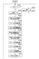
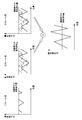
- FIG. 6 is a flowchart illustrating processing of the imaging apparatus according to the first embodiment of the present technology. It is a figure which shows an example of the detection result in the image data of the 1st frame. It is a figure which shows an example of the image data of the 2nd frame input into a digital signal processing part. 12 is a flowchart illustrating a process of an imaging device according to a second embodiment of the present technology. It is a figure which shows a mode when the image data of the 2nd frame and the image data of the 3rd frame are added.
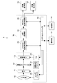
- FIG. 1 is a block diagram illustrating an imaging apparatus 1 according to the first embodiment of the present technology.
- An imaging apparatus 1 shown in FIG. 1 is a digital camera (digital still camera, digital video camera) that can capture still images and moving images.
- the imaging device 1 can reproduce recorded image data.
- the imaging apparatus 1 includes a lens system 10, a diaphragm 11, a liquid crystal ND filter 12 (ND: Neutral Density) (transmittance adjustment unit), an imaging element 13, a control unit 14, an image A display unit 15, an image storage unit 16, an operation unit 17, and a storage unit 18 are provided.
- the control unit 14 includes a system controller 19, a lens driver 20, a liquid crystal ND driver 21, a timing generator 22 (TG), an analog signal processing unit 23, an A / D conversion unit 24, and a digital signal processing unit 25. including.
- the lens system 10 includes various lenses such as a zoom lens and a focus lens, and the subject light is imaged on the exposure surface of the image sensor 13 by these lenses.
- the diaphragm 11 is configured to be able to mechanically adjust the amount of subject light by adjusting the opening degree.
- the diaphragm 11 is disposed behind the lens system 10, but the diaphragm 11 is disposed in the optical path inside the lens system 10 (for example, between the zoom lens and the focus lens). It may be.
- the lens driver 20 controls the positions of the zoom lens, the focus lens, and the diaphragm 11 and the opening degree of the diaphragm 11 according to an instruction from the system controller 19.
- the liquid crystal ND filter 12 is configured to be capable of adjusting the light transmittance (adjusting the density) according to the applied voltage, and by adjusting the transmittance according to the applied voltage. The amount of subject light incident on the image sensor 13 is adjusted.
- the liquid crystal ND driver 21 controls the transmittance (density) of the liquid crystal ND filter 12 by controlling the voltage applied to the liquid crystal ND filter 12 in accordance with an instruction from the system controller 19.
- the image sensor 13 is configured by a CMOS (Complementary Metal Oxide Semiconductor) sensor, a CCD (Charge Coupled Device) sensor, or the like.
- the image sensor 13 captures an image by exposing subject light incident through the liquid crystal ND filter 12.
- the imaging device 13 has a plurality of pixels (R pixel, G pixel, B pixel), converts subject light incident on the exposure surface into an electronic signal by photoelectric conversion for each pixel, The obtained three primary color signals (R, G, B) are output to the analog signal processing unit 23 as analog image data.
- Timing generator 22 (TG: Timing Generator) generates a drive pulse necessary for driving the image sensor 13 in accordance with an instruction from the system controller 19 and supplies it to the image sensor 13.
- the timing generator 22 drives the imaging device 13 to capture a subject image (electronic shutter) and acquire the subject image.
- the exposure time at the time of image capturing is controlled by adjusting the shutter speed of the image sensor 13 by the timing generator 22.
- the analog signal processing unit 23 executes CDS processing (CDS: Correlated Double Sampling), gain processing, and the like on the image signal output from the image sensor 13.
- CDS processing CDS: Correlated Double Sampling
- gain processing and the like on the image signal output from the image sensor 13.
- the A / D conversion unit 24 converts the analog image data output from the analog signal processing unit 23 into digital image data, and outputs the digital image data to the digital signal processing unit 25.
- the digital signal processing unit 25 performs various digital signals such as noise removal processing, white balance adjustment processing, color correction processing, edge enhancement processing, and gamma correction processing on the digital image data output from the A / D conversion unit 24.
- the process is executed and output to the image display unit 15 and the image storage unit 16. Further, in the high frame rate mode described later, the digital signal processing unit 25 detects the digital image data (first image data) of the first frame output from the A / D conversion unit 24 to detect the system controller 19. Output to.
- the image display unit 15 is configured by a liquid crystal display, an organic EL (EL) display, or the like.
- the image display unit 15 displays various images on the screen.
- the image display unit 15 displays the through image on the screen by displaying the image data output from the digital signal processing unit 25 in real time.
- the image display unit 15 executes processing for reproducing the image recorded in the image storage unit 16.
- the through image is displayed on the screen so that the user can adjust the angle of view when capturing a still image or a moving image.
- the image storage unit 16 stores image data output from the digital signal processing unit 25 and metadata related to the image data (for example, date and time when the image data was acquired).
- the image storage unit 16 is configured by, for example, a semiconductor memory, an optical disc, an HD (hard disc), and the like.
- the image storage unit 16 may be fixed inside the imaging device 1 or may be configured to be detachable from the imaging device 1.
- the system controller 19 is configured by, for example, a CPU (Central Processing Unit) and the like, and comprehensively controls each unit of the imaging apparatus 1. Specific processing of the system controller 19 will be described in detail later in the column of operation description.
- a CPU Central Processing Unit
- a still image capturing mode for capturing a still image a moving image capturing mode (recording mode) for capturing a moving image
- a playback mode for reproducing an image recorded in the image storage unit 16 are prepared.
- two modes of a normal mode and a high frame rate mode are prepared in the still image capturing mode and the moving image capturing mode, respectively.
- the normal mode is a mode in which imaging is performed at a normal frame rate (for example, 30 fps).
- a normal frame rate for example, 30 fps
- imaging is performed at a frame rate (for example, 60 fps) that is twice the normal frame rate
- image data for the first frame is converted to image data for the second frame (first frame).
- This is a mode used as an image for estimating the exposure amount of the image sensor 13 when imaging (2 image data) (for calculating the transmittance of the liquid crystal ND filter 12).
- the storage unit 18 includes a nonvolatile memory (for example, ROM (Read Only Memory)) in which various programs and various data are fixedly stored, and a volatile memory (as a work area of the system controller 19).
- ROM Read Only Memory
- RAM Random Access Memory
- the program may be read from a portable recording medium such as an optical disk or a semiconductor memory, or may be downloaded from a server device on a network.
- a transmittance vs. voltage table, a saturated pixel element ratio vs. exposure amount table, and an exposure amount vs. transmittance table are stored as the various data.
- the transmittance vs. voltage table is a table showing the relationship between the transmittance of the liquid crystal ND filter 12 and the applied voltage.
- the system controller 19 refers to this transmittance vs. voltage table, reads the applied voltage corresponding to the desired transmittance, and applies the read applied voltage. An instruction is given to the liquid crystal ND driver 21.
- the saturated pixel ratio versus exposure amount table is a table used in the high frame rate mode.
- the saturation pixel ratio vs. exposure amount table the relationship between the ratio of the saturation pixel number to the total number of pixels in the image data of the first frame and the exposure amount of the image sensor 13 when imaging the image data of the second frame is shown.
- the relationship between the two is related so that the exposure amount of the image sensor 13 decreases as the ratio of the saturated pixel number to the total number of pixels increases.
- the system controller 19 estimates the exposure amount of the image sensor 13 at the time of acquiring the image data of the second frame based on the image data of the first frame in the high frame rate mode, this saturation pixel ratio versus exposure amount table , The exposure amount of the image sensor 13 is estimated.
- the exposure amount vs. transmittance table is a table used in the high frame rate mode similarly to the saturated pixel ratio vs. exposure amount table.
- the exposure amount versus transmittance table the relationship between the estimated exposure amount and the second transmittance which is the transmittance of the liquid crystal ND filter 12 at the time of acquiring the second image data is shown.
- the relationship between the two is related so that the second transmittance increases as the estimated exposure amount increases.
- the system controller 19 calculates the second transmittance based on the estimated exposure amount of the image sensor 13, the system controller 19 calculates the second transmittance with reference to the exposure amount versus transmittance table.
- the operation unit 17 includes, for example, a power switch, a shutter button, a recording button, a setting button, a mode switching button, and the like.
- the power switch is an operation unit 17 for switching on / off the power of the imaging apparatus 1.
- the shutter button is an operation unit 17 for recording image data as still image data in the still image capturing mode
- the recording button is an operation unit for recording image data as moving image data in the moving image capturing mode. 17.
- the setting button is used, for example, to adjust the position of the zoom lens, the focus lens, and the diaphragm 11 or to adjust the opening degree of the diaphragm 11.
- the setting button is used for adjusting the electronic shutter, changing the gain value in the gain processing of the analog signal processing unit 23, and changing the setting value of various processes by the digital signal processing unit 25. It is done.
- the mode switching button is an operation unit 17 for switching between the normal mode and the high frame rate mode.
- the operation unit 17 may be realized by a mechanical push button type operation unit 17 or may be realized by a touch sensor such as a capacitance type or a resistance film type provided on the image display unit 15. Good.
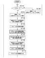
- FIG. 2 is a flowchart showing processing of the imaging apparatus 1 according to the first embodiment.
- the system controller 19 determines whether or not the current mode is the high frame rate mode (step 101). Note that switching between the normal mode and the high frame rate mode can be performed by a mode switching button.
- the system controller 19 sets the imaging rate to a normal frame rate (for example, 30 fps). (Step 102).
- the system controller 19 instructs the timing generator 22 to cause the image sensor 13 to perform image capturing at a normal frame rate.
- the system controller 19 sets the imaging rate to a frame rate (high frame rate: 60 fps, for example) that is twice the normal frame rate (Ste 103). Then, the system controller 19 instructs the timing generator 22 to cause the imaging device 13 to perform imaging at a frame rate that is twice the normal frame rate.
- the system controller 19 instructs the liquid crystal ND driver 21 to set the transmittance of the liquid crystal ND filter 12 to the first transmittance at the first frame imaging timing in the high frame rate imaging (step). 104).
- the system controller 19 reads the applied voltage corresponding to the first transmittance with reference to the transmittance vs. voltage table stored in the storage unit 18 and applies the read applied voltage. An instruction is given to the liquid crystal ND driver 21.
- the first transmittance is a predetermined constant value.
- the system controller 19 may calculate the voltage in real time according to a program instead of referring to the table.
- the transmittance of the liquid crystal ND filter 12 When the transmittance of the liquid crystal ND filter 12 is set to the first transmittance, the subject image that has passed through the liquid crystal ND filter 12 set to the first transmittance is combined with the exposure surface of the image sensor 13, and the image sensor. 13 captures the first frame image (step 105).
- the image data (first image data) of the first frame is subjected to CDS processing and gain processing by the analog signal processing unit 23 and then converted to a digital signal by the A / D conversion unit 24.
- the digital signal processing unit 25 detects the image data of the first frame converted into the digital signal and outputs the detection result to the system controller 19.
- the image data of the first frame is not data used for display and / or recording, so the image data of the first frame is not output to the image display unit 15 and the image storage unit 16.
- the system controller 19 sets an appropriate exposure amount for the exposure amount in the image sensor 13 when capturing the image of the second frame. (Step 106).
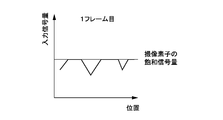
- FIG. 3 is a diagram illustrating an example of a detection result in the image data of the first frame.
- the horizontal axis indicates the position of each pixel, and the vertical axis indicates the input signal amount to the digital signal processing unit 25.
- the exposure amount of the image sensor 13 is too large, and the input signal amount in some pixels has reached the saturation signal amount, and the gradation is impaired in the portion that has reached the saturation signal amount.
- An example of the case where it is closed is shown. It should be noted that the digital signal processing unit 25 cannot restore the portion where the gradation is impaired in this way.
- the system controller 19 determines the number of pixels that have reached the saturation signal amount based on the detection result of the image data of the first frame.
- the system controller 19 calculates the ratio of the number of pixels reaching the saturation signal amount to the total number of pixels. Based on this ratio, the exposure amount when the second frame image is captured is estimated.
- the system controller 19 estimates that the higher the ratio in the first frame, the more the image should be taken in the second frame.
- the system controller 19 refers to the saturation pixel ratio vs. exposure amount table stored in the recording unit and reads the exposure amount corresponding to the saturation pixel ratio to capture an image of the second frame. It is estimated how much the appropriate exposure amount is. In estimating the exposure amount, the system controller 19 may calculate the exposure amount in real time according to a program instead of referring to the table.
- the system controller 19 After estimating the exposure amount appropriate for capturing the image of the second frame, the system controller 19 then determines the image of the second frame based on the estimated exposure amount.
- a second transmittance that is the transmittance of the liquid crystal ND filter 12 when imaging is calculated (step 107).
- the system controller 19 calculates the second transmittance by reading the second transmittance corresponding to the estimated exposure amount with reference to the exposure amount vs. transmittance table.
- the system controller 19 may calculate the second transmittance in real time according to a program instead of referring to the table.
- the system controller 19 After calculating the second transmittance, the system controller 19 then sets the transmittance of the liquid crystal ND filter 12 to the second transmittance at the imaging timing of the second frame in the high frame rate imaging. An instruction is issued to the ND driver 21 (step 108).
- the system controller 19 refers to the transmittance vs. voltage table stored in the storage unit 18, reads the applied voltage corresponding to the second transmittance, and applies the read applied voltage. An instruction is given to the liquid crystal ND driver 21.
- the transmittance of the liquid crystal ND filter 12 is changed from the transmittance of 1 within a period (for example, 16.7 ms) after the imaging is performed until the next imaging is performed. It is necessary to change to the second transmittance. Such a change in transmittance in a short period can be realized by using the liquid crystal ND filter 12 having high-speed response.
- the transmittance of the liquid crystal ND filter 12 is set to the second transmittance
- the subject image transmitted through the liquid crystal ND filter 12 set to the second transmittance is coupled to the exposure surface of the image sensor 13, and the image sensor 13 captures the second frame image (step 109).
- the second frame of image data (second image data) is subjected to CDS processing and gain processing by the analog signal processing unit 23, and then converted to a digital signal by the A / D conversion unit 24.
- the digital signal processing unit 25 acquires the second frame of image data converted into a digital signal.
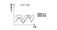
- FIG. 4 is a diagram illustrating an example of image data of the second frame input to the digital signal processing unit 25.
- the horizontal axis indicates the position of each pixel, and the vertical axis indicates the input signal amount to the digital signal processing unit 25.
- the waveform when the transmittance of the liquid crystal ND filter 12 is the first transmittance is shown by a broken line
- the waveform when the transmittance of the liquid crystal ND filter 12 is the second transmittance Is shown as a solid line.
- the transmittance of the liquid crystal ND filter 12 is set to an appropriate transmittance (second transmittance), and the exposure amount of the imaging device 13 is set. Is set to an appropriate exposure amount. Therefore, it is possible to prevent the signal of each pixel output from the image sensor 13 from reaching the saturation signal amount.
- the digital signal processing unit 25 When acquiring the second frame of image data converted into a digital signal, the digital signal processing unit 25 performs various digital signal processing such as noise removal processing, white balance adjustment processing, color correction processing, edge enhancement processing, and gamma correction processing. Execute. Then, the digital signal output unit outputs the second frame of image data that has been subjected to digital signal processing (step 110).
- various digital signal processing such as noise removal processing, white balance adjustment processing, color correction processing, edge enhancement processing, and gamma correction processing.
- the output rate (for example, 30 fps) of the image data output from the digital signal processing unit 25 is The imaging rate by the imaging device 13 (for example, 60 fps) is half.
- the system controller 19 executes processing for setting the imaging rate to a rate that is twice the output rate for outputting the image data.
- the digital signal processing unit 25 executes different processing depending on whether the current mode is the still image capturing mode or the moving image capturing mode when outputting the image data of the second frame.
- the digital signal processing unit 25 when the current mode is the still image capturing mode, the digital signal processing unit 25 outputs the second frame of image data to the image display unit 15 to display a through image on the screen of the image display unit 15. Then, the digital signal processing unit 25 outputs the image data of the second frame to the image storage unit 16 in accordance with the timing when the shutter button is operated, and stores it as a still image.
- the digital signal processing unit 25 When the current mode is the moving image capturing mode, the digital signal processing unit 25 outputs the second frame of image data to the image display unit 15 in the same manner as when the mode is the still image capturing mode. A through image is displayed on the screen. On the other hand, unlike the case where the mode is the still image capturing mode, the digital image processing unit always outputs the second frame of image data to the image storage unit 16.
- the second frame image is stored in the image storage unit 16 as an image constituting a part of the moving image.
- the system controller 19 returns to step 101 again and determines whether or not the current mode is the high frame rate mode.
- step 101 If the current mode is the high frame rate mode (YES in step 101), a series of processing from step 103 to step 110 is repeatedly executed.
- Step 104 after the second round it is necessary to change the transmittance of the liquid crystal ND filter 12 from the transmittance of 2 to the first transmittance within a predetermined period (for example, 16.7 ms). This can be realized by using the liquid crystal ND filter 12 having high-speed response.
- the image data of the first frame is used as image data for estimating the exposure amount (appropriate exposure amount) when imaging the image data of the second frame. Further, the image data of the first frame is used as image data for calculating the second transmittance (appropriate transmittance) that is the transmittance of the liquid crystal ND filter 12 when the image data of the second frame is captured. It has been. Then, the transmittance of the liquid crystal ND filter 12 is set to the second transmittance, the image data of the second frame is acquired, and the image of the second frame is output without outputting the image data of the first frame. The Thereby, in this embodiment, the image data output from the image pick-up element 13 can be output as image data of appropriate exposure amount.
- the second transmittance is set so that the exposure amount of the image sensor 13 becomes an appropriate exposure amount. For this reason, in the image data of the second frame, the signal of each pixel output from the image sensor 13 can be prevented from reaching the saturation signal amount (see FIG. 4). For this reason, in this embodiment, it is possible to output image data that makes the best use of the dynamic range of the image sensor 13.
- the second transmittance when calculating the second transmittance, is calculated based on the ratio of the number of pixels reaching the saturation signal amount to the total number of pixels in the image data of the first frame. Calculated. For this reason, in the image data of the second frame, it is possible to effectively prevent the signal of each pixel output from the image sensor 13 from reaching the saturation signal amount.
- the image data output from the image sensor 13 can be always output as image data with an appropriate exposure amount.
- the diaphragm 11 has a problem that the response speed is slow and it is difficult to change the opening to another opening within a predetermined period (for example, 16.7 ms).
- the transmittance can be changed to another transmittance within a predetermined period (for example, 16.7 ms).
- a method of setting a minus gain in the gain processing of the analog signal processing unit 23 is also conceivable.
- the width of the minus gain in the analog signal processing unit 23 is only about ⁇ 3 dB, it is not effective as a method for adjusting the exposure amount.
- noise may vary between frames.
- this embodiment since it is not necessary to employ such a method, it is possible to prevent noise from occurring.
- a plurality of ND filters filters whose transmittance is not variable unlike the liquid crystal ND filter 12
- filters filters whose transmittance is not variable unlike the liquid crystal ND filter 12
- the response speed is slow, and since the density is finite, there is a problem that an appropriate exposure amount cannot be adjusted.
- an invalid frame is generated when the ND filter is switched to another ND filter.
- this embodiment since the liquid crystal ND filter 12 is used, these problems do not occur.
- the exposure adjustment according to the present technology and these exposure adjustments can also be combined, not to exclude the exposure adjustment by the electronic shutter, the aperture 11, the analog signal processing, and the ND filter.
- an appropriate exposure amount when the image data of the second frame is imaged is estimated based on the image data of the first frame, and the second transmittance is calculated based on the estimated exposure amount.
- the case of calculating is described.
- the second transmittance may be directly calculated based on the image data of the first frame.
- step 103 to step 110 In the above description, the case where a series of processing from step 103 to step 110 is repeatedly executed has been described. On the other hand, the processing of step 103 to step 110 does not necessarily have to be repeatedly executed, and may be completed once.
- the image sensor 13 performs imaging at a normal frame rate, and performs digital signal processing at a normal frame rate.
- Image data is output from the unit 25. This image data is output to the image display unit 15 and displayed on the screen of the image display unit 15 as a through image.
- the imaging device 13 performs imaging at a high frame rate in accordance with this timing.
- the image data of the first frame is used for estimating the exposure amount when the image data of the second frame is imaged (for calculating the second transmittance), and only the image data of the second frame is used. Is output.
- the image data of the second frame is output to the image display unit 15 and displayed on the screen of the image display unit 15 as a through image, and is output to the image storage unit 16 and is stored as still image data in the image storage unit 16. Saved.
- high frame rate imaging is performed at a predetermined cycle, and otherwise, imaging can be performed at a normal frame rate.
- imaging is performed at a high frame rate at a cycle of once every five times.
- the system controller 19 may automatically switch between the normal mode and the high frame rate mode.
- the system controller 19 performs imaging at a normal frame rate in the normal mode, and in the image data captured at this frame rate, the ratio of pixels reaching the saturation signal amount is predetermined. It is determined whether or not the threshold value is exceeded. When the image data exceeding the threshold is continuous (for example, about 10 images), the normal mode is switched to the high frame rate mode.
- the first transmittance may be variably controlled.
- the system controller 19 determines the ratio of pixels that have reached the saturation signal amount, and stores this ratio in the storage unit 18, thereby Generate history.
- the system controller 19 changes the first transmittance based on the tendency of the ratio change. For example, when the tendency of the change in the ratio is an increase, the system controller 19 changes the first transmittance so as to reduce the first transmittance, and the tendency of the change in the ratio decreases. When it is a tendency, the first transmittance is changed so as to increase the first transmittance.
- the system controller 19 may change the first transmittance based on the second transmittance. In this case, every time the second controller calculates the second transmittance, the system controller 19 stores the second transmittance in the storage unit 18 and generates a second transmittance history.
- the system controller 19 changes the first transmittance based on the tendency of the second transmittance to change. For example, when the change tendency of the second transmittance is increasing, the system controller 19 changes the first transmittance so as to increase the first transmittance, and the second transmittance. When the tendency of the change is a decreasing trend, the first transmittance is changed so as to reduce the first transmittance.
- the difference between the first transmittance and the second transmittance is reduced, so that the frame rate in high frame rate imaging is further increased. It is possible to deal with cases.
- the exposure amount when the image data of the first frame is imaged when the exposure amount when the image data of the first frame is imaged is large, the exposure amount when the image data of the second frame is imaged accordingly.
- the case of decreasing (decreasing the second transmittance) has been described.
- the exposure amount when capturing image data of the first frame is small, the exposure amount when capturing image data of the second frame is increased accordingly (the second transmittance is increased). Can also be increased).
- the image data of the third frame is captured in addition to the image data of the second frame.
- the image data of the second frame and the image data of the third frame are added (synthesized), and the added image data is output from the digital signal output unit as high dynamic range image data. This is different from the first embodiment described above. Therefore, this point will be mainly described.
- a normal mode and a high dynamic range mode are prepared as modes.
- the mode switching button can switch between these two modes.
- switching between the two modes of the normal mode and the high dynamic range mode will be described, but it is also possible to switch between the three modes of the normal mode, the high frame rate mode, and the high dynamic range mode. .
- FIG. 5 is a flowchart illustrating processing of the imaging apparatus 1 according to the second embodiment. As shown in FIG. 5, first, the system controller 19 determines whether or not the current mode is the high dynamic range mode (step 201).
- the system controller 19 sets the imaging rate to a normal frame rate (for example, 30 fps). (Step 202).
- the system controller 19 sets the imaging rate to a frame rate (high frame rate: 90 fps, for example) that is three times the normal frame rate. (Step 203). That is, the system controller 19 sets the imaging rate to a rate that is three times the output rate for outputting image data.
- the system controller 19 instructs the liquid crystal ND driver 21 to set the transmittance of the liquid crystal ND filter 12 to the first transmittance at the first frame imaging timing in the high frame rate imaging (step). 204).
- the system controller 19 causes the image sensor 13 to capture an image of the first frame (step 205).
- the digital signal processing unit 25 detects the image data of the first frame converted into the digital signal and outputs the detection result to the system controller 19. Note that the image data of the first frame is not output to the image display unit 15 and the image storage unit 16.
- the system controller 19 estimates an appropriate exposure amount in the image sensor 13 when the second frame and third frame images are captured based on the detection result of the first frame image data (step 206). .
- the system controller 19 calculates a second transmittance based on the estimated exposure amount (step 207). ).
- the system controller 19 After calculating the second transmittance, the system controller 19 then sets the transmittance of the liquid crystal ND filter 12 to the second transmittance at the imaging timing of the second frame in the high frame rate imaging. An instruction is issued to the ND driver 21 (step 208).
- the system controller 19 causes the image sensor 13 to capture an image of the second frame (step 209).
- the system controller 19 causes the image sensor 13 to capture an image of the third frame at the imaging timing of the third frame in high frame rate imaging (step 210).
- the digital signal output unit adds the image data of the second frame and the image data of the third frame (step 211). Then, the digital signal output unit outputs the added image data as high dynamic range image data to the image display unit 15 and the image storage unit 16 (step 212).
- the output rate (for example, 30 fps) of the image data is 1/3 of the imaging rate (for example, 90 fps) by the image sensor 13.
- the system controller 19 When the high dynamic image data is output from the digital signal output unit, the system controller 19 returns to step 101 again and determines whether or not the current mode is the high dynamic range mode.
- step 201 If the current mode is the high dynamic range mode (YES in step 201), a series of processing from step 203 to step 212 is repeatedly executed.
- FIG. 6 is a diagram showing a state when the image data of the second frame and the image data of the third frame are added.
- the second transmittance is set so that the exposure amount of the image sensor 13 becomes an appropriate exposure amount. .
- the signal of each pixel reaches the saturation signal amount. Can be prevented.
- high dynamic range image data that retains the tone of the high luminance signal that could not be output due to the limitation of the saturation signal amount of the image sensor 13 is digitally displayed. The signal can be output from the signal processing unit 25.
- the first transmittance may be variably controlled as in the modification of the first embodiment. Also in the second embodiment, similarly to the first embodiment, when the exposure amount when the image data of the first frame is captured is small, the second frame and the third frame are accordingly changed. It is also possible to increase the exposure amount when capturing image data of the eye (or more) (increase the second transmittance).
- This technique can also take the following composition.
- a transmittance adjusting unit capable of adjusting the light transmittance according to the applied voltage;
- An image sensor that performs imaging by exposing light transmitted through the transmittance adjusting unit; and
- First image data is acquired by setting the transmittance of the transmittance adjusting unit to the first transmittance and causing the image sensor to perform imaging, and based on the first image data, the image sensor
- the second transmittance is calculated in order to perform imaging with an appropriate exposure amount, and the transmittance of the transmittance adjusting unit is set to the second transmittance so that the imaging device performs imaging.
- a control unit that acquires the second image data and outputs the acquired second image data.
- the imaging apparatus acquires the second image data and the third image data by setting the transmittance of the transmittance adjusting unit to the second transmittance and causing the imaging unit to perform imaging, An imaging apparatus that adds the second image data and the third image data and outputs the added image data.
- the imaging apparatus variably controls the first transmittance.
- the imaging apparatus according to any one of (1) to (3) above, The image sensor has a plurality of pixels, When calculating the second transmittance based on the first image data, the control unit determines a ratio of the number of pixels reaching the saturation signal amount to the total number of pixels in the first image data. An imaging device that calculates the second transmittance based on the ratio.
- the imaging apparatus obtains the first image data, calculates the second transmittance, obtains the second image data, and repeats a series of processes for outputting the second image data.
- the imaging device to execute.
- the imaging apparatus obtains the first image data, calculates the second transmittance, obtains the second image data and the third image data, and obtains the second image data and the second image data.
- An image pickup apparatus that repeats and executes a series of processes for adding the three image data and outputting the added image data.
- the transmittance adjusting unit is a liquid crystal ND filter (ND: Neutral Density).
- the transmittance of the transmittance adjusting unit capable of adjusting the light transmittance according to the applied voltage is set to the first transmittance, and the image sensor that exposes the light transmitted through the transmittance adjusting unit is imaged.
- the first image data is acquired by performing Based on the first image data, a second transmittance is calculated in order to cause the imaging device to capture an image with an appropriate exposure amount,
- the second image data is obtained by setting the transmittance of the transmittance adjusting unit to the second transmittance and causing the image sensor to perform imaging, An image data output method for outputting the acquired second image data.
- the transmittance of the transmittance adjusting unit capable of adjusting the light transmittance according to the applied voltage is set to the first transmittance, and the imaging device that exposes the light transmitted through the transmittance adjusting unit performs imaging.
- Obtaining the first image data by: Calculating a second transmittance based on the first image data to cause the imaging device to capture an image with an appropriate exposure amount; Acquiring the second image data by setting the transmittance of the transmittance adjusting unit to the second transmittance and causing the image sensor to perform imaging, and outputting the acquired second image data
- a program that executes the steps to be performed is set to the first transmittance, and the imaging device that exposes the light transmitted through the transmittance adjusting unit performs imaging.
Abstract
Description
前記透過率調整部は、印加電圧に応じて光の透過率を調整可能とされる。
前記撮像素子は、前記透過率調整部を透過した光を露光することにより撮像を行う。
前記制御部は、前記透過率調整部の透過率を第1の透過率に設定して前記撮像素子に撮像を行わせることによって第1の画像データを取得し、前記第1の画像データに基づいて、前記撮像素子において適切な露光量で撮像を行わせるため第2の透過率を算出し、前記透過率調整部の透過率を前記第2の透過率に設定して前記撮像素子に撮像を行わせることによって第2の画像データを取得し、取得された前記第2の画像データを出力する。
この場合、前記制御部は、前記第1の画像データに基づいて前記第2の透過率を算出するとき、第1の画像データにおける全画素数に対する、飽和信号量に達している画素数の比率を判定し、前記比率に基づいて、第2の透過率を算出してもよい。
前記第1の画像データに基づいて、前記撮像素子において適切な露光量で撮像を行わせるため第2の透過率が算出される。
前記透過率調整部の透過率が前記第2の透過率に設定されて前記撮像素子に撮像を行わせることによって第2の画像データが取得される。
取得された前記第2の画像データが出力される。
印加電圧に応じて光の透過率を調整可能な透過率調整部の透過率を第1の透過率に設定して、前記透過率調整部を透過した光を露光する撮像素子に撮像を行わせることによって第1の画像データを取得するステップと、
前記第1の画像データに基づいて、前記撮像素子において適切な露光量で撮像を行わせるため第2の透過率を算出するステップと、
前記透過率調整部の透過率を前記第2の透過率に設定して前記撮像素子に撮像を行わせることによって第2の画像データを取得するステップと
取得された前記第2の画像データを出力するステップと
を実行させる。
[撮像装置1の全体構成及び各部の構成]
図1は、本技術の第1実施形態に係る撮像装置1を示すブロック図である。図1に示す撮像装置1は、静止画及び動画を撮像可能なデジタルカメラ(デジタルスチルカメラ、デジタルビデオカメラ)である。また、この撮像装置1は、記録された画像データを再生可能とされている。
次に、第1実施形態に係る撮像装置1による処理について具体的に説明する。図2は、第1実施形態に係る撮像装置1の処理を示すフローチャートである。
以上のように、本実施形態では、1フレーム目の画像データが、2フレーム目の画像データを撮像するときの露光量(適切な露光量)を推定するための画像データとして用いられている。また、1フレーム目の画像データが、2フレーム目の画像データを撮像するときの液晶NDフィルタ12の透過率である第2の透過率(適切な透過率)を算出すための画像データとして用いられている。そして、液晶NDフィルタ12の透過率が第2の透過率に設定されて2フレーム目の画像データが取得され、1フレーム目の画像データが出力されることなく、2フレーム目の画像が出力される。これにより、本実施形態では、撮像素子13から出力された画像データを適切な露光量の画像データとして出力することができる。
第1実施形態の説明では、1フレーム目の画像データに基づいて、2フレーム目の画像データを撮像するときの適切な露光量を推定し、推定された露光量に基づいて第2の透過率を算出する場合について説明した。一方、1フレーム目の画像データに基づいて、直接的に、第2の透過率が算出されてもよい。
次に、本技術の第2実施形態について説明する。第2実施形態以降の説明では、上述の第1実施形態と同様の構成及び機能を有する各部については同一符号を付し、説明を省略又は簡略化する。また、第2実施形態以降の説明では、上述の第1実施形態(及び第1実施形態変形例)と異なる点を中心に説明する。
図5は、第2実施形態に係る撮像装置1の処理を示すフローチャートである。図5に示すように、まず、システムコントローラ19は、現在のモードがハイダイナミックレンジモードであるかどうかを判定する(ステップ201)。
第2の実施形態の説明では、ND液晶フィルタの透過率が第2の透過率に設定されている状態で、2枚の画像データが撮像され、この2枚の画像データが加算されてデジタル信号処理部25から出力される場合について説明した。一方、ND液晶フィルタの透過率が第2の透過率に設定されている状態で、3枚以上の画像データが撮像され、この3枚以上の画像データが加算されてデジタル信号処理部25から出力されてもよい。
(1) 印加電圧に応じて光の透過率を調整可能な透過率調整部と、
前記透過率調整部を透過した光を露光することにより撮像を行う撮像素子と、
前記透過率調整部の透過率を第1の透過率に設定して前記撮像素子に撮像を行わせることによって第1の画像データを取得し、前記第1の画像データに基づいて、前記撮像素子において適切な露光量で撮像を行わせるため第2の透過率を算出し、前記透過率調整部の透過率を前記第2の透過率に設定して前記撮像素子に撮像を行わせることによって第2の画像データを取得し、取得された前記第2の画像データを出力する制御部と
を具備する撮像装置。
(2) 上記(1)に記載の撮像装置であって、
前記制御部は、前記透過率調整部の透過率を前記第2の透過率に設定して前記撮像部に撮像を行わせることによって前記第2の画像データ及び第3の画像データを取得し、前記第2の画像データ及び前記第3の画像データを加算し、加算された画像データを出力する
撮像装置。
(3) 上記(1)又は(2)に記載の撮像装置であって、
前記制御部は、前記第1の透過率を可変に制御する
撮像装置。
(4) 上記(1)~(3)のうちいずれか1つに記載の撮像装置であって、
前記撮像素子は、複数の画素を有し、
前記制御部は、前記第1の画像データに基づいて前記第2の透過率を算出するとき、第1の画像データにおける全画素数に対する、飽和信号量に達している画素数の比率を判定し、前記比率に基づいて、第2の透過率を算出する
撮像装置。
(5) 上記(1)~(4)のうちいずれか1つに記載の撮像装置であって、
前記制御部は、前記第1の画像データを取得し、前記第2の透過率を算出し、前記第2の画像データを取得し、前記第2の画像データを出力する一連の処理を繰り返して実行する
撮像装置。
(6) 上記(2)~(5)のうちいずれか1つに記載の撮像装置であって、
前記制御部は、前記第1の画像データを取得し、前記第2の透過率を算出し、前記第2の画像データ及び前記第3の画像データを取得し、前記第2の画像データ及び第3の画像データを加算し、加算された画像データを出力する一連の処理を繰り返して実行する
撮像装置。
(7) 上記(1)~(6)のうちいずれか1つに記載の撮像装置であって、
前記透過率調整部は、液晶NDフィルタ(ND:Neutral Density)である
撮像装置。
(8) 印加電圧に応じて光の透過率を調整可能な透過率調整部の透過率を第1の透過率に設定して、前記透過率調整部を透過した光を露光する撮像素子に撮像を行わせることによって第1の画像データを取得し、
前記第1の画像データに基づいて、前記撮像素子において適切な露光量で撮像を行わせるため第2の透過率を算出し、
前記透過率調整部の透過率を前記第2の透過率に設定して前記撮像素子に撮像を行わせることによって第2の画像データを取得し、
取得された前記第2の画像データを出力する
画像データの出力方法。
(9) 撮像装置に、
印加電圧に応じて光の透過率を調整可能な透過率調整部の透過率を第1の透過率に設定して、前記透過率調整部を透過した光を露光する撮像素子に撮像を行わせることによって第1の画像データを取得するステップと、
前記第1の画像データに基づいて、前記撮像素子において適切な露光量で撮像を行わせるため第2の透過率を算出するステップと、
前記透過率調整部の透過率を前記第2の透過率に設定して前記撮像素子に撮像を行わせることによって第2の画像データを取得するステップと
取得された前記第2の画像データを出力するステップと
を実行させるプログラム。
10…レンズ系
12…液晶NDフィルタ
13…撮像素子
14…制御部
15…画像表示部
16…画像保存部
17…操作部
18…記憶部
19…システムコントローラ
20…レンズドライバ
21…NDドライバ
22…タイミングジェネレータ
23…アナログ信号処理部
24…A/D変換部
25…デジタル信号処理部
Claims (9)
- 印加電圧に応じて光の透過率を調整可能な透過率調整部と、
前記透過率調整部を透過した光を露光することにより撮像を行う撮像素子と、
前記透過率調整部の透過率を第1の透過率に設定して前記撮像素子に撮像を行わせることによって第1の画像データを取得し、前記第1の画像データに基づいて、前記撮像素子において適切な露光量で撮像を行わせるため第2の透過率を算出し、前記透過率調整部の透過率を前記第2の透過率に設定して前記撮像素子に撮像を行わせることによって第2の画像データを取得し、取得された前記第2の画像データを出力する制御部と
を具備する撮像装置。 - 請求項1に記載の撮像装置であって、
前記制御部は、前記透過率調整部の透過率を前記第2の透過率に設定して前記撮像部に撮像を行わせることによって前記第2の画像データ及び第3の画像データを取得し、前記第2の画像データ及び前記第3の画像データを加算し、加算された画像データを出力する
撮像装置。 - 請求項1に記載の撮像装置であって、
前記制御部は、前記第1の透過率を可変に制御する
撮像装置。 - 請求項1に記載の撮像装置であって、
前記撮像素子は、複数の画素を有し、
前記制御部は、前記第1の画像データに基づいて前記第2の透過率を算出するとき、第1の画像データにおける全画素数に対する、飽和信号量に達している画素数の比率を判定し、前記比率に基づいて、第2の透過率を算出する
撮像装置。 - 請求項1に記載の撮像装置であって、
前記制御部は、前記第1の画像データを取得し、前記第2の透過率を算出し、前記第2の画像データを取得し、前記第2の画像データを出力する一連の処理を繰り返して実行する
撮像装置。 - 請求項2に記載の撮像装置であって、
前記制御部は、前記第1の画像データを取得し、前記第2の透過率を算出し、前記第2の画像データ及び前記第3の画像データを取得し、前記第2の画像データ及び第3の画像データを加算し、加算された画像データを出力する一連の処理を繰り返して実行する
撮像装置。 - 請求項1に記載の撮像装置であって、
前記透過率調整部は、液晶NDフィルタ(ND:Neutral Density)である
撮像装置。 - 印加電圧に応じて光の透過率を調整可能な透過率調整部の透過率を第1の透過率に設定して、前記透過率調整部を透過した光を露光する撮像素子に撮像を行わせることによって第1の画像データを取得し、
前記第1の画像データに基づいて、前記撮像素子において適切な露光量で撮像を行わせるため第2の透過率を算出し、
前記透過率調整部の透過率を前記第2の透過率に設定して前記撮像素子に撮像を行わせることによって第2の画像データを取得し、
取得された前記第2の画像データを出力する
画像データの出力方法。 - 撮像装置に、
印加電圧に応じて光の透過率を調整可能な透過率調整部の透過率を第1の透過率に設定して、前記透過率調整部を透過した光を露光する撮像素子に撮像を行わせることによって第1の画像データを取得するステップと、
前記第1の画像データに基づいて、前記撮像素子において適切な露光量で撮像を行わせるため第2の透過率を算出するステップと、
前記透過率調整部の透過率を前記第2の透過率に設定して前記撮像素子に撮像を行わせることによって第2の画像データを取得するステップと
取得された前記第2の画像データを出力するステップと
を実行させるプログラム。
Priority Applications (3)
| Application Number | Priority Date | Filing Date | Title |
|---|---|---|---|
| US15/122,501 US9930263B2 (en) | 2014-03-31 | 2015-02-13 | Imaging apparatus, for determining a transmittance of light for a second image based on an analysis of a first image |
| JP2016511341A JP6497382B2 (ja) | 2014-03-31 | 2015-02-13 | 撮像装置、画像データの出力方法及びプログラム |
| EP15772187.9A EP3128740B1 (en) | 2014-03-31 | 2015-02-13 | Image-capturing device, method for outputting image data, and program |
Applications Claiming Priority (2)
| Application Number | Priority Date | Filing Date | Title |
|---|---|---|---|
| JP2014-074389 | 2014-03-31 | ||
| JP2014074389 | 2014-03-31 |
Publications (1)
| Publication Number | Publication Date |
|---|---|
| WO2015151386A1 true WO2015151386A1 (ja) | 2015-10-08 |
Family
ID=54239742
Family Applications (1)
| Application Number | Title | Priority Date | Filing Date |
|---|---|---|---|
| PCT/JP2015/000678 WO2015151386A1 (ja) | 2014-03-31 | 2015-02-13 | 撮像装置、画像データの出力方法及びプログラム |
Country Status (4)
| Country | Link |
|---|---|
| US (1) | US9930263B2 (ja) |
| EP (1) | EP3128740B1 (ja) |
| JP (2) | JP6497382B2 (ja) |
| WO (1) | WO2015151386A1 (ja) |
Cited By (5)
| Publication number | Priority date | Publication date | Assignee | Title |
|---|---|---|---|---|
| JP2018101937A (ja) * | 2016-12-21 | 2018-06-28 | キヤノン株式会社 | 撮像装置、その制御方法、および制御プログラム |
| JP2020529159A (ja) * | 2017-07-27 | 2020-10-01 | レイセオン カンパニー | 多重化高ダイナミックレンジ画像 |
| JP2021511520A (ja) * | 2018-01-23 | 2021-05-06 | コリア リサーチ インスティトゥート オブ スタンダード アンド サイエンス | 位相シフト偏向測定法で非線形応答特性を補償するためのシステム及び方法 |
| WO2021255975A1 (ja) * | 2020-06-17 | 2021-12-23 | ソニーグループ株式会社 | 撮像装置、撮像制御装置、撮像装置の制御方法、プログラム |
| WO2023248589A1 (ja) * | 2022-06-23 | 2023-12-28 | 株式会社ジャパンディスプレイ | カメラモジュール |
Families Citing this family (9)
| Publication number | Priority date | Publication date | Assignee | Title |
|---|---|---|---|---|
| US11457158B2 (en) * | 2017-07-27 | 2022-09-27 | Nec Corporation | Location estimation device, location estimation method, and program recording medium |
| JP2019128380A (ja) * | 2018-01-22 | 2019-08-01 | キヤノン株式会社 | 撮像装置及びその制御方法 |
| TWM580195U (zh) * | 2018-07-17 | 2019-07-01 | 先進光電科技股份有限公司 | 可調變進光量光學成像系統 |
| US11199735B2 (en) * | 2019-03-28 | 2021-12-14 | Lumcolor | Smart optical filter for pixel-selectively adjusting light intensity |
| CN110809122A (zh) * | 2019-11-11 | 2020-02-18 | 中国电子科技集团公司第四十四研究所 | 应用于cmos图像传感器的动态扩展方法 |
| CN110830697A (zh) * | 2019-11-27 | 2020-02-21 | Oppo广东移动通信有限公司 | 控制方法、电子装置和存储介质 |
| US11537027B2 (en) * | 2020-01-19 | 2022-12-27 | Blue River Technology Inc. | Methods and apparatus for using a controllable physical light filter as part of an image capture system and for processing captured images |
| US20220232156A1 (en) * | 2021-01-19 | 2022-07-21 | Semiconductor Components Industries, Llc | Imaging system with an electronic shutter |
| CN114554050B (zh) * | 2022-02-08 | 2024-02-27 | 维沃移动通信有限公司 | 图像处理方法、装置和设备 |
Citations (4)
| Publication number | Priority date | Publication date | Assignee | Title |
|---|---|---|---|---|
| JP2012084814A (ja) * | 2010-10-14 | 2012-04-26 | Panasonic Corp | 固体撮像装置、半導体装置及びカメラ |
| WO2013031429A1 (ja) * | 2011-08-31 | 2013-03-07 | 富士フイルム株式会社 | レンズ装置、カメラシステム、露出制御方法 |
| JP2013088597A (ja) * | 2011-10-18 | 2013-05-13 | Sony Corp | 動作制御装置および動作制御方法、撮像装置、並びにプログラム |
| JP2013251724A (ja) * | 2012-05-31 | 2013-12-12 | Olympus Imaging Corp | 撮影機器 |
Family Cites Families (12)
| Publication number | Priority date | Publication date | Assignee | Title |
|---|---|---|---|---|
| JP2000092383A (ja) * | 1998-09-16 | 2000-03-31 | Konica Corp | 画像入力装置、画像入力方法、透過フィルタ調整方法、透過フィルタ測定方法及び画像出力方法 |
| US6702483B2 (en) * | 2000-02-17 | 2004-03-09 | Canon Kabushiki Kaisha | Optical element |
| US7245325B2 (en) * | 2000-03-17 | 2007-07-17 | Fujifilm Corporation | Photographing device with light quantity adjustment |
| JP2008242230A (ja) * | 2007-03-28 | 2008-10-09 | Fujifilm Corp | 撮影装置、撮影システム、および撮影方法 |
| WO2010118177A1 (en) * | 2009-04-08 | 2010-10-14 | Zoran Corporation | Exposure control for high dynamic range image capture |
| JP5412953B2 (ja) * | 2009-05-20 | 2014-02-12 | リコーイメージング株式会社 | 撮像装置 |
| JP2012019337A (ja) * | 2010-07-07 | 2012-01-26 | Olympus Corp | 画像処理装置及び方法並びにプログラム |
| JP2012104994A (ja) | 2010-11-09 | 2012-05-31 | Sony Corp | 入力装置、入力方法、プログラム及び記録媒体 |
| JP5701664B2 (ja) * | 2011-04-07 | 2015-04-15 | オリンパス株式会社 | 撮像装置 |
| JP5910852B2 (ja) * | 2011-10-18 | 2016-04-27 | ソニー株式会社 | 動作制御装置および動作制御方法、撮像装置、並びにプログラム |
| TWI464526B (zh) * | 2013-08-08 | 2014-12-11 | Quanta Comp Inc | 高動態範圍影像曝光時間控制方法 |
| JP2015198292A (ja) * | 2014-03-31 | 2015-11-09 | ソニー株式会社 | 撮像装置、フリッカの補正方法及びプログラム |
-
2015
- 2015-02-13 EP EP15772187.9A patent/EP3128740B1/en active Active
- 2015-02-13 US US15/122,501 patent/US9930263B2/en active Active
- 2015-02-13 JP JP2016511341A patent/JP6497382B2/ja active Active
- 2015-02-13 WO PCT/JP2015/000678 patent/WO2015151386A1/ja active Application Filing
-
2019
- 2019-03-11 JP JP2019043923A patent/JP6680377B2/ja not_active Expired - Fee Related
Patent Citations (4)
| Publication number | Priority date | Publication date | Assignee | Title |
|---|---|---|---|---|
| JP2012084814A (ja) * | 2010-10-14 | 2012-04-26 | Panasonic Corp | 固体撮像装置、半導体装置及びカメラ |
| WO2013031429A1 (ja) * | 2011-08-31 | 2013-03-07 | 富士フイルム株式会社 | レンズ装置、カメラシステム、露出制御方法 |
| JP2013088597A (ja) * | 2011-10-18 | 2013-05-13 | Sony Corp | 動作制御装置および動作制御方法、撮像装置、並びにプログラム |
| JP2013251724A (ja) * | 2012-05-31 | 2013-12-12 | Olympus Imaging Corp | 撮影機器 |
Non-Patent Citations (1)
| Title |
|---|
| See also references of EP3128740A4 * |
Cited By (8)
| Publication number | Priority date | Publication date | Assignee | Title |
|---|---|---|---|---|
| JP2018101937A (ja) * | 2016-12-21 | 2018-06-28 | キヤノン株式会社 | 撮像装置、その制御方法、および制御プログラム |
| JP2020529159A (ja) * | 2017-07-27 | 2020-10-01 | レイセオン カンパニー | 多重化高ダイナミックレンジ画像 |
| JP2022071177A (ja) * | 2017-07-27 | 2022-05-13 | レイセオン カンパニー | 多重化高ダイナミックレンジ画像 |
| JP7077395B2 (ja) | 2017-07-27 | 2022-05-30 | レイセオン カンパニー | 多重化高ダイナミックレンジ画像 |
| JP2021511520A (ja) * | 2018-01-23 | 2021-05-06 | コリア リサーチ インスティトゥート オブ スタンダード アンド サイエンス | 位相シフト偏向測定法で非線形応答特性を補償するためのシステム及び方法 |
| JP7001835B2 (ja) | 2018-01-23 | 2022-01-20 | コリア リサーチ インスティトゥート オブ スタンダード アンド サイエンス | 位相シフト偏向測定法で非線形応答特性を補償するためのシステム及び方法 |
| WO2021255975A1 (ja) * | 2020-06-17 | 2021-12-23 | ソニーグループ株式会社 | 撮像装置、撮像制御装置、撮像装置の制御方法、プログラム |
| WO2023248589A1 (ja) * | 2022-06-23 | 2023-12-28 | 株式会社ジャパンディスプレイ | カメラモジュール |
Also Published As
| Publication number | Publication date |
|---|---|
| US20170078550A1 (en) | 2017-03-16 |
| US9930263B2 (en) | 2018-03-27 |
| EP3128740B1 (en) | 2020-04-01 |
| EP3128740A4 (en) | 2017-12-06 |
| JP2019097213A (ja) | 2019-06-20 |
| JP6497382B2 (ja) | 2019-04-10 |
| JPWO2015151386A1 (ja) | 2017-04-13 |
| EP3128740A1 (en) | 2017-02-08 |
| JP6680377B2 (ja) | 2020-04-15 |
Similar Documents
| Publication | Publication Date | Title |
|---|---|---|
| JP6680377B2 (ja) | 撮像装置、撮像方法及びプログラム | |
| TWI360349B (en) | Digital imaging apparatus with camera shake compen | |
| JP5123137B2 (ja) | 撮像装置および撮像方法 | |
| US9681060B2 (en) | Imaging apparatus, method of correcting flicker, and program | |
| JP5746521B2 (ja) | 撮像装置及びその制御方法、プログラム並びに記憶媒体 | |
| JP2010160311A (ja) | 撮像装置 | |
| JP2010054730A (ja) | 合焦位置検出装置、撮像装置及び合焦位置検出方法 | |
| JP4764712B2 (ja) | ディジタル・カメラおよびその制御方法 | |
| JP4958635B2 (ja) | 撮像装置及びその制御方法 | |
| JP5948997B2 (ja) | 撮像装置及び撮像方法 | |
| WO2021251260A1 (ja) | 撮像装置、及び撮像方法 | |
| JP2006253970A (ja) | 撮像装置、シェーディング補正データ作成方法およびプログラム | |
| JP2015056758A (ja) | 撮像装置、その制御方法、及び制御プログラム | |
| JP6090565B2 (ja) | 撮像装置、撮像方法及びプログラム | |
| JP5455485B2 (ja) | 撮像装置 | |
| JP5022802B2 (ja) | 撮像装置及びその制御方法 | |
| WO2015182021A1 (ja) | 撮像制御装置、撮像装置および撮像制御方法 | |
| JP2011035740A (ja) | 撮像装置及び撮像方法 | |
| JP5169540B2 (ja) | 撮像装置および撮像方法 | |
| JP2011029719A5 (ja) | ||
| JP2010148045A (ja) | 撮像装置および撮像方法 | |
| JP2004336245A (ja) | 補正装置 | |
| JP5504905B2 (ja) | 撮像装置 | |
| JP2009147436A (ja) | 撮像装置 | |
| JP2016140057A (ja) | 撮像装置 |
Legal Events
| Date | Code | Title | Description |
|---|---|---|---|
| 121 | Ep: the epo has been informed by wipo that ep was designated in this application |
Ref document number: 15772187 Country of ref document: EP Kind code of ref document: A1 |
|
| ENP | Entry into the national phase |
Ref document number: 2016511341 Country of ref document: JP Kind code of ref document: A |
|
| REEP | Request for entry into the european phase |
Ref document number: 2015772187 Country of ref document: EP |
|
| WWE | Wipo information: entry into national phase |
Ref document number: 15122501 Country of ref document: US |
|
| NENP | Non-entry into the national phase |
Ref country code: DE |