WO2015151161A1 - Assembly block with servomotor, and assembly block kit - Google Patents

Assembly block with servomotor, and assembly block kit Download PDF

Info

Publication number
WO2015151161A1
WO2015151161A1 PCT/JP2014/059463 JP2014059463W WO2015151161A1 WO 2015151161 A1 WO2015151161 A1 WO 2015151161A1 JP 2014059463 W JP2014059463 W JP 2014059463W WO 2015151161 A1 WO2015151161 A1 WO 2015151161A1
Authority
WO
WIPO (PCT)
Prior art keywords
block
connecting means
assembly
protrusion
servo motor
Prior art date
Application number
PCT/JP2014/059463
Other languages
French (fr)
Japanese (ja)
Inventor
泰正 宇野
Original Assignee
株式会社アーテック
Priority date (The priority date is an assumption and is not a legal conclusion. Google has not performed a legal analysis and makes no representation as to the accuracy of the date listed.)
Filing date
Publication date
Application filed by 株式会社アーテック filed Critical 株式会社アーテック
Priority to PL14888480T priority Critical patent/PL3127588T3/en
Priority to JP2014561633A priority patent/JP6039702B2/en
Priority to SG11201607868QA priority patent/SG11201607868QA/en
Priority to EP14888480.2A priority patent/EP3127588B1/en
Priority to CN201480075133.3A priority patent/CN106102853B/en
Priority to PCT/JP2014/059463 priority patent/WO2015151161A1/en
Priority to KR1020167023719A priority patent/KR102087772B1/en
Priority to ES14888480T priority patent/ES2752126T3/en
Publication of WO2015151161A1 publication Critical patent/WO2015151161A1/en
Priority to US15/279,623 priority patent/US10124269B2/en

Links

Images

Classifications

    • AHUMAN NECESSITIES
    • A63SPORTS; GAMES; AMUSEMENTS
    • A63HTOYS, e.g. TOPS, DOLLS, HOOPS OR BUILDING BLOCKS
    • A63H33/00Other toys
    • A63H33/04Building blocks, strips, or similar building parts
    • A63H33/042Mechanical, electrical, optical, pneumatic or hydraulic arrangements; Motors
    • AHUMAN NECESSITIES
    • A63SPORTS; GAMES; AMUSEMENTS
    • A63HTOYS, e.g. TOPS, DOLLS, HOOPS OR BUILDING BLOCKS
    • A63H29/00Drive mechanisms for toys in general
    • A63H29/22Electric drives
    • AHUMAN NECESSITIES
    • A63SPORTS; GAMES; AMUSEMENTS
    • A63HTOYS, e.g. TOPS, DOLLS, HOOPS OR BUILDING BLOCKS
    • A63H33/00Other toys
    • A63H33/04Building blocks, strips, or similar building parts
    • A63H33/06Building blocks, strips, or similar building parts to be assembled without the use of additional elements
    • A63H33/08Building blocks, strips, or similar building parts to be assembled without the use of additional elements provided with complementary holes, grooves, or protuberances, e.g. dovetails
    • A63H33/086Building blocks, strips, or similar building parts to be assembled without the use of additional elements provided with complementary holes, grooves, or protuberances, e.g. dovetails with primary projections fitting by friction in complementary spaces between secondary projections, e.g. sidewalls

Definitions

  • Patent Document 2 introduces an embodiment in which a caterpillar of a bulldozer is driven by a motor via a gear.
  • the rotation block includes at least one side surface parallel to the rotation axis and has at least one connecting means on the side surface. By doing so, the rotation block can be directly connected to another assembly block positioned in a direction perpendicular to the rotation axis.
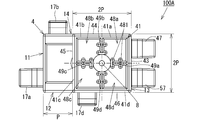
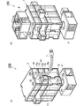
  • the outer surface 41 can be equally divided into four squares 41a, 41b, 41c, and 41d each having a side length P, as shown by a virtual line (two-dot chain line) in FIG. 48a to 48d are configured such that the protrusion to be fitted is positioned at the center of the sections 41a to 41d by the ribs 481 and 482, and the insertion direction of the protrusion is perpendicular to the outer surface 41.
  • the pitch of adjacent recesses is P.
  • the assembly block 100 with servo motor not only the outer surfaces 43 and 53 but also the side surfaces 43 to 46 and 53 to 56 are provided with recesses and protrusions, so that the assembly block can be assembled into various shapes and also rotated. Diversified, the variety of shapes and the variety of the state of rotation combined, you can enjoy more diverse forms of work. Further, the rotation block 4 and the idle block 5 can be directly connected to other assembly blocks positioned in the axial direction of the rotation shaft 3 and to other assembly blocks positioned in a direction perpendicular to the rotation shaft 3.

Abstract

Provided are an assembly block with a servomotor and an assembly block kit that make it possible to assemble various products without the need for special parts to be used mainly in a drive shaft. This assembly block (100A) with a servomotor has: a block main body (1) that includes a connection means comprising a projection (17) or a recess; a servomotor (2); and a rotating shaft (3) that is driven to rotate by the servomotor (2). The assembly block can be coupled to another assembly block by engaging the connection means with a connection means of the other assembly block. The assembly block (100A) with a servomotor also has a rotating block (4) that comprises a polyhedron, that has a connection means comprising a recess or a projection on a surface thereof, and that rotates by being fixed to one end of the rotating shaft (3). This assembly block kit has the assembly block (100A) with a servomotor, and a basic block that can be connected to the assembly block (100A).

Description

サーボモータ付組立ブロック、及び組立ブロックキットAssembly block with servo motor and assembly block kit
 この発明は、凹部に突起を嵌合することで組立てる組立ブロックにサーボモータを設けたサーボモータ付組立ブロック、及び該サーボモータ付組立ブロックを含んだ組立ブロックキットに関する。 The present invention relates to an assembly block with a servo motor in which a servo motor is provided in an assembly block to be assembled by fitting a protrusion into a recess, and an assembly block kit including the assembly block with a servo motor.
 古くから、直方体や立方体、三角柱等の多面体の表面に突起と凹部を備え、凹部に突起を嵌合させることにより結合して、所望の形状に組み立てる遊戯用、学習用の組立ブロックが広く普及している。さらに、近年では、組立ブロックにモータを備えさせ、可動部分をモータにより作動させるものが、人気を博している。 For a long time, assembling blocks for play and learning that have a protrusion and a recess on the surface of a polyhedron such as a rectangular parallelepiped, a cube, a triangular prism, etc., and are assembled by fitting the protrusion into the recess and assembled into a desired shape, have been widely used ing. Further, in recent years, it has become popular to provide an assembly block with a motor and operate a movable part with the motor.
 例えば、特許文献1では、モータを搭載し歯軌条に沿って走行する機関車の組立ブロックキットが提案されている。これはモータによって駆動される駆動軸に歯車を取り付け、歯車を歯軌条に噛合させて回転させることにより、機関車を走行させるものである。 For example, Patent Document 1 proposes an assembly block kit for a locomotive equipped with a motor and traveling along a tooth rail. In this method, a locomotive is caused to travel by attaching a gear to a drive shaft driven by a motor and engaging the gear with a tooth rail and rotating the gear.
 また、特許文献2では、サーボモータやブザー等の機能を発現する機能発現手段の他に機能発現手段を制御する制御手段と、ネットワークを介して他の組立ブロックと通信を行う通信手段とを内蔵することで、簡単な配線で複雑な動作が可能な組立ブロックが提案されている。特許文献2では、モータによりギアを介してブルドーザーのキャタピラを駆動させる実施例が紹介されている。 Moreover, in patent document 2, the control means which controls a function expression means other than the function expression means which expresses functions, such as a servomotor and a buzzer, and the communication means which communicates with another assembly block via a network are incorporated. Thus, an assembly block capable of performing a complicated operation with simple wiring has been proposed. Patent Document 2 introduces an embodiment in which a caterpillar of a bulldozer is driven by a motor via a gear.
特公平7-61382号公報Japanese Patent Publication No. 7-61382 特開平10-108985号公報Japanese Patent Laid-Open No. 10-108985
 しかし、特許文献1では、モータの用途が機関車への使用に限定されるため、機関車のキットを丸ごと購入しなくてはならないという問題があり、特許文献2のブロックでは、モータによって回動する回動軸の用途ごとに用意された特別なパーツを逐一買い揃えなくてはならないという問題がある。
 本発明は、上記課題に鑑みてなされたものであり、専ら回動軸にのみ用いる特別なパーツを必要とすることなく、サーボモータを内蔵したブロックを多様に用いることができるサーボモータ付組立ブロック、及び該サーボモータ付組立ブロックを含む組立ブロックキットの提供を目的とする。
However, in Patent Document 1, since the use of the motor is limited to use in a locomotive, there is a problem that the entire locomotive kit must be purchased. In the block of Patent Document 2, the motor is rotated by the motor. There is a problem that special parts prepared for each use of the rotating shaft must be purchased one by one.
The present invention has been made in view of the above problems, and an assembly block with a servo motor that can use a variety of blocks incorporating a servo motor without requiring special parts used exclusively for a rotating shaft. And an assembly block kit including the assembly block with a servo motor.
 上記課題を解決するためになされた本発明のモータ付組立ブロックは、表面に突起、又は凹部からなる連結手段を少なくとも1つ有するブロック本体と、前記ブロック本体に設けられるサーボモータと、前記サーボモータにより回転駆動される回動軸と、を有し、前記連結手段を他の組立ブロックの突起、又は凹部からなる連結手段に嵌合させることにより、前記他の組立ブロックに結合可能なサーボモータ付組立ブロックであって、前記回動軸の一端部に固定されて前記回動軸とともに回動する回動ブロックを備え、前記回動ブロックは、多面体からなり、表面に凹部、又は突起からなる連結手段を有することを特徴とする。 An assembly block with a motor of the present invention made to solve the above-mentioned problems is a block main body having at least one connecting means consisting of a protrusion or a recess on the surface, a servo motor provided in the block main body, and the servo motor A rotation shaft that is driven by rotation, and with a servo motor that can be coupled to the other assembly block by fitting the connection means to a connection means comprising a protrusion or recess of the other assembly block. An assembly block comprising a rotation block fixed to one end of the rotation shaft and rotating together with the rotation shaft. The rotation block is formed of a polyhedron and includes a recess or a protrusion on the surface. It has the means.
 このように、本発明に係るサーボモータ付組立ブロックでは、サーボモータにより駆動される回動軸の一端部に、突起や凹部を有する多面体のブロックを備えるため、突起や凹部を有する多面体の他の組立ブロックを、回動軸に直接連結することができる。 As described above, in the assembly block with a servomotor according to the present invention, the polyhedral block having protrusions and recesses is provided at one end portion of the rotating shaft driven by the servomotor. The assembly block can be directly connected to the pivot shaft.
 前記回動ブロックは、前記回動軸に平行な側面を少なくとも1つ備え、当該側面に少なくとも1つの連結手段を有することが好ましい。こうすることで、回動ブロックを回動軸に垂直な方向に位置する他の組立ブロックに直接連結することができる。 It is preferable that the rotation block includes at least one side surface parallel to the rotation axis and has at least one connecting means on the side surface. By doing so, the rotation block can be directly connected to another assembly block positioned in a direction perpendicular to the rotation axis.
 本発明のサーボモータ付組立ブロックは、多面体からなり、表面に突起、又は凹部からなる連結手段を有し、前記回動軸の他端側の延長線回りに回動するよう前記ブロック本体に軸支される遊動ブロックを備え、前記遊動ブロックは、前記ブロック本体、及び前記回動軸から独立して回動することが好ましい。
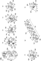
 こうすることで、回動ブロックと遊動ブロックの両方を固定するとブロック本体のみが回動し、回動ブロックのみを固定するとブロック本体と遊動ブロックとが回動し、遊動ブロックのみを固定すると回動ブロックのみが回動するため、回動の態様を3種類に設けることができる。
 また、回動ブロックと遊動ブロックの両方を他の組立ブロックに結合する場合に、回動ブロックと遊動ブロックが互いに独立して回動可能であるため別々に操作でき、回動ブロックと遊動ブロックを他の組立ブロックに結合しやすい。
The assembly block with a servo motor of the present invention comprises a polyhedron, has a connecting means consisting of a protrusion or a recess on the surface, and is pivoted on the block main body so as to rotate around an extension line on the other end side of the rotating shaft. It is preferable that a floating block is supported, and the floating block rotates independently from the block main body and the rotation shaft.
In this way, when both the rotating block and the idle block are fixed, only the block body rotates, when only the rotary block is fixed, the block body and idle block rotate, and when only the idle block is fixed, it rotates. Since only the block rotates, three types of rotation modes can be provided.
In addition, when both the rotation block and the idle block are coupled to another assembly block, the rotation block and the idle block can be rotated independently of each other, so that the rotation block and the idle block can be operated separately. Easy to connect to other assembly blocks.
 前記遊動ブロックは、前記回動軸に平行な少なくとも1つの側面を備え、当該側面に少なくとも1つの連結手段を有することが好ましい。こうすることで、遊動ブロックを回動軸に垂直な方向に位置する他の組立ブロックに直接連結することができる。 It is preferable that the floating block has at least one side surface parallel to the rotation shaft and has at least one connecting means on the side surface. By doing so, the floating block can be directly connected to another assembly block positioned in a direction perpendicular to the rotation axis.
 本発明に係る組立ブロックキットは、直方体をなし表面に突起と凹部を少なくとも1つずつ含む連結手段を備えた基本ブロックと、上記のサーボモータ付組立ブロックと、を備え、前記基本ブロックは、各面が1辺の長さをPとする正方形の区分(以下単に「区分」ともいう。)を一又は複数個並べた長方形からなり、前記基本ブロックの連結手段は、前記区分の中央に設けられ、非対向の2つの区分のそれぞれに設けられる突起と凹部を少なくとも1組含み、前記サーボモータ付組立ブロックの連結手段は、前記基本ブロックの突起又は凹部に嵌合可能に形成されるとともに、前記ブロック本体の連結手段は、前記回動軸に垂直な連結方向を有しており、前記遊動ブロックの側面の連結手段は、突起と凹部を少なくとも1つずつ含み、前記ブロック本体の連結手段と、前記遊動ブロックの側面の連結手段の連結方向を一致させて連結方向に平行に見た際に、前記ブロック本体の連結手段と、前記遊動ブロック側面の連結手段の中心間を結んだ線分を対角線とし、前記回動軸に平行な縦辺を有する長方形(以下、「第1長方形」ともいう。)の縦辺及び横編がともにPの整数倍に形成されている。
 このように、基本ブロックの各面を、上記区分が一又は複数個並んだ長方形に形成し、基本ブロックの連結手段を当該区分の中心に設け、基本ブロックの突起と凹部が非対向な位置にある2つの区分に設けられ、かつ、ブロック本体と回動ブロックの連結手段における上記第1長方形の縦辺及び横辺の長さが、基本ブロックの連結手段のピッチPの整数倍に形成されているため、ブロック本体の連結手段と回動ブロックの連結手段とを一又は複数の基本ブロックで連結できる。
An assembly block kit according to the present invention includes a basic block having a rectangular parallelepiped shape and provided with connecting means including at least one protrusion and a recess on a surface thereof, and the assembly block with a servo motor described above. The surface is a rectangle in which one or a plurality of square sections (hereinafter also simply referred to as “sections”) having a side length of P are arranged, and the basic block connecting means is provided at the center of the sections. , Including at least one pair of protrusions and recesses provided in each of the two non-opposing sections, and the connecting means of the assembly block with servomotor is formed to be fitted to the protrusions or recesses of the basic block, and The connecting means of the block body has a connecting direction perpendicular to the rotation axis, and the connecting means on the side surface of the floating block includes at least one protrusion and a recess, When the connecting means of the lock main body and the connecting means of the side surface of the floating block are aligned and viewed in parallel with the connecting direction, the center of the connecting means of the block main body and the connecting means of the side surface of the floating block is between The line connecting the two lines is a diagonal line, and the vertical and horizontal knitting of a rectangle having a vertical side parallel to the rotation axis (hereinafter also referred to as “first rectangle”) is formed to be an integral multiple of P. .
In this way, each surface of the basic block is formed in a rectangle in which one or more of the above sections are arranged, and the connecting means of the basic block is provided at the center of the section, and the protrusions and the recesses of the basic block are in positions where they do not face each other. The lengths of the first and second rectangles in the connecting means between the block main body and the rotating block are formed to be an integral multiple of the pitch P of the connecting means of the basic block. Therefore, the connecting means of the block main body and the connecting means of the rotating block can be connected by one or a plurality of basic blocks.
 本発明に係る組立ブロックキットは、前記サーボモータ付組立ブロックの回動ブロックの側面の連結手段が、突起と凹部を少なくとも1つ含み、前記回動ブロックの側面の連結手段と、前記遊動ブロックの側面の連結手段の連結方向を一致させて連結方向に平行に見た際に、前記回動ブロックの側面の連結手段と、前記遊動ブロックの側面の連結手段の中心間を結んだ線分を対角線とし、前記回動軸に平行な縦辺を有する長方形(以下、「第2長方形」ともいう。)の縦辺及び横編がともにPの整数倍に形成されていることが好ましい。
 このように、回動ブロックと遊動ブロックの側面の連結手段の連結方向を一致させた際に、上記第2長方形の縦辺及び横辺の長さがPの整数倍に形成されているため、回動ブロック側面の連結手段と遊動ブロック側面の連結手段とを基本ブロックで連結することができる。
In the assembly block kit according to the present invention, the connecting means on the side surface of the rotating block of the assembly block with servomotor includes at least one protrusion and a recess, the connecting means on the side surface of the rotating block, and the floating block When the connecting direction of the connecting means on the side surface is matched and viewed in parallel to the connecting direction, a line segment connecting the connecting means on the side surface of the rotating block and the center of the connecting means on the side surface of the floating block is a diagonal line. It is preferable that a vertical side and a horizontal knitting of a rectangle (hereinafter also referred to as “second rectangle”) having a vertical side parallel to the rotation axis are formed to be an integral multiple of P.
Thus, when the connecting directions of the connecting means on the side surfaces of the rotating block and the floating block are matched, the length of the vertical and horizontal sides of the second rectangle is formed to be an integral multiple of P. The connecting means on the side surface of the rotating block and the connecting means on the side surface of the floating block can be connected by the basic block.
 ここで、「連結方向」とは、突起においては突起の突出方向を指し、凹部においては凹部に嵌入する突起の嵌入方向を指すものとする。「整数倍」は、0倍を含むものとする。
また、「非対向の2つの区分」とは、2つの区分のうち1つの区分を含む面に垂直な方向から見た場合に、2つの区分が前後に重ならない区分をいうものとする。
Here, the “connection direction” refers to the protruding direction of the protrusion in the protrusion, and the insertion direction of the protrusion that fits into the recess in the recess. “Integer multiple” includes 0 times.
In addition, “two non-opposing sections” refers to sections in which the two sections do not overlap each other when viewed from a direction perpendicular to the plane including one of the two sections.
 以上説明したように、本発明のサーボモータ付組立ブロック、及び組立ブロックキットによれば、回転軸に設けられた回動ブロックに直接組立ブロックを連結することができるため、ギアやタイヤ、クランク形成用のロッド等を買い揃えなくても、回動する部分を備えた作品を楽しむことができる。 As described above, according to the assembly block with servomotor and the assembly block kit of the present invention, the assembly block can be directly connected to the rotation block provided on the rotation shaft, so that the gear, tire, crank formation You can enjoy works with rotating parts without having to buy rods for use.
本発明の一の実施形態に係るサーボモータ付組立ブロックの斜視図である。It is a perspective view of the assembly block with a servomotor which concerns on one Embodiment of this invention. 図1に示したサーボモータ付組立ブロックの正面図である。It is a front view of the assembly block with a servomotor shown in FIG. 図1に示したサーボモータ付組立ブロックの背面図である。It is a rear view of the assembly block with a servomotor shown in FIG. 図1に示したサーボモータ付組立ブロックの右側面図である。It is a right view of the assembly block with a servomotor shown in FIG. 図1に示したサーボモータ付組立ブロックの左側面図である。It is a left view of the assembly block with a servomotor shown in FIG. 図1に示したサーボモータ付組立ブロックの平面図である。It is a top view of the assembly block with a servomotor shown in FIG. 図1に示したサーボモータ付組立ブロックの底面図である。It is a bottom view of the assembly block with a servomotor shown in FIG. 図6のA-A線断面図である。FIG. 7 is a cross-sectional view taken along line AA in FIG. 6. 図15に示した組立ブロックキットにより組立てた作品例の正面図である。It is a front view of the example of a work assembled by the assembly block kit shown in FIG. 図15の組立ブロックキットにより組立てた別の作品例の斜視図である。It is a perspective view of another work example assembled with the assembly block kit of FIG. 図15の組立ブロックキットで組立てたまた別の作品例の正面図である。It is a front view of another example of a work assembled with the assembly block kit of FIG. 電気配線を切欠き部に収容した様子を示す斜視図である。It is a perspective view which shows a mode that the electrical wiring was accommodated in the notch part. 本発明の他の実施形態に係るサーボモータ付組立ブロックの斜視図である。It is a perspective view of the assembly block with a servomotor which concerns on other embodiment of this invention. 本発明のまた別の実施形態に係るサーボモータ付組立ブロックの斜視図である。It is a perspective view of the assembly block with a servomotor which concerns on another embodiment of this invention. 本発明に係る組立ブロックキットに含まれる(a)サーボモータ付組立ブロック、(b)~(g)基本ブロック、及び(h)付属ブロックを示した斜視図である。FIG. 3 is a perspective view showing (a) an assembly block with a servo motor, (b) to (g) a basic block, and (h) an attached block included in the assembly block kit according to the present invention.
 以下、適宜図面を参照しながら、本発明の実施形態について詳述する。図15は、本発明に係る組立ブロックキット1000を示している。組立ブロック1000は、サーボモータ付組立ブロック100A(以下単に「組立ブロック100A」とも称す。)と、組立ブロック100Aと連結可能な基本ブロック200、300、400、500、600、700、及び付属ブロック800からなる組立ブロックとを備えている。基本ブロック200~700は、各面が1辺の長さPの正方形の区分を並べて形成された長方形に形成されており、区分の中央に設けられる突起と凹部を少なくとも1つずつ有している。このように、区分の中央に突起や凹部を設けることで、区分同士を正確に重ねることができる。また基本ブロック200~700の突起は断面が正方形をなし凹部に対し90度ずつ回転させた姿勢で嵌合して固定できるよう形成されている。
 尚、本発明のサーボモータ付組立ブロック、及び組立ブロックキットは、以下の実施形態に限られるものではない。
Hereinafter, embodiments of the present invention will be described in detail with reference to the drawings as appropriate. FIG. 15 shows an assembly block kit 1000 according to the present invention. The assembly block 1000 includes an assembly block 100A with a servo motor (hereinafter also simply referred to as “assembly block 100A”), basic blocks 200, 300, 400, 500, 600, 700, and an accessory block 800 that can be connected to the assembly block 100A. The assembly block which consists of. Each of the basic blocks 200 to 700 is formed in a rectangle formed by arranging square sections each having a side length P, and has at least one protrusion and a recess provided in the center of the section. . Thus, by providing a protrusion or a recess at the center of the sections, the sections can be accurately overlapped. The protrusions of the basic blocks 200 to 700 are formed so that they have a square cross section and can be fitted and fixed in a posture rotated by 90 degrees with respect to the recess.
Note that the assembly block with servomotor and the assembly block kit of the present invention are not limited to the following embodiments.
 基本ブロック200は、図15(b)に示すように、立方体をなし、各面が区分を4つ並べた正方形に形成されている。基本ブロック200は、非対向の区分に設けられる突起207と凹部208とを有している。 As shown in FIG. 15 (b), the basic block 200 has a cubic shape, and each surface is formed in a square having four sections. The basic block 200 has a protrusion 207 and a recess 208 provided in a non-opposing section.
 基本ブロック300~600は、図15(c)~(f)に示すように、直方体をなし、区分を2つ並べた長方形からなる4つの面と区分を4つ並べた正方形からなる2つの面とで形成されている。基本ブロック300~600は、それぞれ突起307,407,507,607を有し、突起307,407,507,607と非対向の区分に設けられる凹部308,408,508,608をそれぞれ有している。 As shown in FIGS. 15 (c) to 15 (f), the basic blocks 300 to 600 are formed as a rectangular parallelepiped, and are composed of four surfaces composed of a rectangle in which two segments are arranged and two surfaces composed of a square in which four segments are arranged. And is formed. The basic blocks 300 to 600 have protrusions 307, 407, 507, and 607, respectively, and have recesses 308, 408, 508, and 608 provided in sections not facing the protrusions 307, 407, 507, and 607, respectively. .
 基本ブロック700は、縦・横・高さがP×2P×10Pの長尺の直方体からなり、突起707と、突起707と非対向の区分に設けられる複数の凹部708を有している。
 付属ブロック800は、区分4つを並べた正方形を2面備えた三角柱からなる。
 基本ブロック200~700及び付属ブロック800は、同じ面内で隣接する突起又は凹部の中心間のピッチがPとなるよう構成されている。
The basic block 700 is formed of a long rectangular parallelepiped having a height, width, and height of P × 2P × 10P, and includes a protrusion 707 and a plurality of recesses 708 provided in a section not facing the protrusion 707.
The accessory block 800 is formed of a triangular prism having two squares arranged in four sections.
The basic blocks 200 to 700 and the accessory block 800 are configured such that the pitch between the centers of adjacent protrusions or recesses in the same plane is P.
 サーボモータ付組立ブロック100は、図1~図8に示すように、ブロック本体1と、ブロック本体1内部に設けられるサーボモータ2(図8参照)と、サーボモータ2にギアを介して回転駆動される回動軸3(図8参照)と、回動軸3の一端側に固定される回動ブロック4と、回動軸3の他端側においてブロック本体1に軸支される遊動ブロック5と、内部に設けられる制御基板6と、サーボモータ2及び制御基板6に電力やサーボモータ2を制御するための情報を伝達する電気配線7(図12参照)とを備えている。第1図から第8図においては、電気配線7の記載は省略している。 As shown in FIG. 1 to FIG. 8, the assembly block 100 with a servo motor is driven to rotate through a block main body 1, a servo motor 2 (see FIG. 8) provided in the block main body 1, and a gear to the servo motor 2. The rotating shaft 3 (see FIG. 8), the rotating block 4 fixed to one end side of the rotating shaft 3, and the floating block 5 pivotally supported by the block body 1 on the other end side of the rotating shaft 3. And a control board 6 provided inside, and an electric wiring 7 (see FIG. 12) for transmitting electric power and information for controlling the servo motor 2 to the servo motor 2 and the control board 6. In FIG. 1 to FIG. 8, description of the electrical wiring 7 is omitted.
 ブロック本体1は、略直方体をなし、回動軸3に平行な第1面11、第2面12、第3面13、及び第4面14、と回動軸3に垂直な第5面15、及び第6面16とを備えている。第1面11から第6面16は、長方形をなし、第1面から第4面は、角筒状の突起17a,17b,17c,17dをそれぞれ備えている。突起17a,17b,17c,17dは、突出方向に垂直な外周面及び内周面の断面が正方形をなしている The block body 1 has a substantially rectangular parallelepiped shape, and includes a first surface 11, a second surface 12, a third surface 13, a fourth surface 14 parallel to the rotation shaft 3, and a fifth surface 15 perpendicular to the rotation shaft 3. , And the sixth surface 16. The first surface 11 to the sixth surface 16 have a rectangular shape, and the first surface to the fourth surface have projections 17a, 17b, 17c, and 17d each having a rectangular tube shape. As for protrusion 17a, 17b, 17c, 17d, the cross section of the outer peripheral surface and inner peripheral surface perpendicular | vertical to a protrusion direction has comprised the square.
 第1面11は、平坦面からなる。第2面から第4面は、外周に沿ってリブ19が設けられ、内側には縦横に交差するリブ18が設けられており、第2面から第4面に組立ブロック200~800を連結すると、リブ18,19の先端縁に組立ブロック200~800の表面が当接する。第2面12からは、図12に示すように、電気配線7が延出しているため、第2面12のリブ18及びリブ19には、第2面12に基本ブロック200~800を連結した際に電気配線7が邪魔にならないよう電気配線7を収容するための切欠き部18a,19aが設けられている。 The first surface 11 is a flat surface. Ribs 19 are provided along the outer periphery of the second surface to the fourth surface, and ribs 18 that intersect vertically and horizontally are provided on the inner side. When the assembly blocks 200 to 800 are connected from the second surface to the fourth surface, The surfaces of the assembly blocks 200 to 800 are brought into contact with the leading edges of the ribs 18 and 19. As shown in FIG. 12, since the electrical wiring 7 extends from the second surface 12, the basic blocks 200 to 800 are connected to the second surface 12 to the ribs 18 and 19 of the second surface 12. Notches 18a and 19a for accommodating the electrical wiring 7 are provided so that the electrical wiring 7 does not get in the way.
 サーボモータ2は、電気配線7を通じて供給される電力と、電気配線7から制御基板6を介して伝達される情報によって、回動軸3を駆動する。回動軸3の一端側となるブロック本体1の第5面15には、回動軸3に固定されて回動軸3とともに回動する回動ブロック4が設けられている。 Servo motor 2 drives rotating shaft 3 based on electric power supplied through electric wiring 7 and information transmitted from electric wiring 7 through control board 6. A rotation block 4 that is fixed to the rotation shaft 3 and rotates together with the rotation shaft 3 is provided on the fifth surface 15 of the block body 1 that is one end side of the rotation shaft 3.
 回動ブロック4は、扁平の直方体をなし、回動軸3に垂直で正方形をなす外面41及び内面42と、回動軸3に平行で、縦の長さがP、横の長さが2Pの長方形からなる側面43~46と、内部空間を平面視で縦横に仕切る4つの仕切り壁49a,49b,49c,49dとを備えている。回動ブロック4は、内面42の中心で、回動軸3と共に回動するよう回動軸3の先端に固定されている。 The rotation block 4 has a flat rectangular parallelepiped shape, and is parallel to the outer surface 41 and the inner surface 42 which are perpendicular to the rotation shaft 3 and form a square, and is parallel to the rotation shaft 3. The vertical length is P and the horizontal length is 2P. Side walls 43 to 46, and four partition walls 49a, 49b, 49c, and 49d that partition the internal space vertically and horizontally in plan view. The rotation block 4 is fixed to the tip of the rotation shaft 3 so as to rotate together with the rotation shaft 3 at the center of the inner surface 42.
 外面41は、図7に示すように、1辺の長さが2Pの正方形からなり、仕切り壁49a~49dによって仕切られる4つの凹部48a,48b,48c,48dを備え、概ね全面が開口している。仕切り壁49a~49dは、両面に凹部48a~48dの結合方向(凹部48a~48dに突起が侵入する方向、図2乃至図5の上下方向)に延びる2条のリブ481が設けられ、片面に後述する凹部48e~48hの結合方向(凹部48e~48fに突起が侵入する方向)に延びる2条のリブ482が設けられている。外面41は、図7に仮想線(2点鎖線)で境界を示したように、1辺の長さがPである4つの正方形からなる区分41a,41b,41c,41dに等分でき、凹部48a~48dは、嵌合する突起がリブ481,482により区分41a~41dの中央に位置するように、かつ突起の挿入方向が外面41に垂直になるよう構成されている。凹部48a~48dのうち隣接する凹部のピッチはPである。 As shown in FIG. 7, the outer surface 41 is formed of a square having a side length of 2P, and includes four concave portions 48a, 48b, 48c, and 48d partitioned by partition walls 49a to 49d. Yes. The partition walls 49a to 49d are provided on both sides with two ribs 481 extending in the connecting direction of the recesses 48a to 48d (the direction in which the protrusion enters the recesses 48a to 48d, the vertical direction in FIGS. 2 to 5). Two ribs 482 extending in a connecting direction of recesses 48e to 48h (a direction in which the protrusion enters the recesses 48e to 48f), which will be described later, are provided. The outer surface 41 can be equally divided into four squares 41a, 41b, 41c, and 41d each having a side length P, as shown by a virtual line (two-dot chain line) in FIG. 48a to 48d are configured such that the protrusion to be fitted is positioned at the center of the sections 41a to 41d by the ribs 481 and 482, and the insertion direction of the protrusion is perpendicular to the outer surface 41. Of the recesses 48a to 48d, the pitch of adjacent recesses is P.
 内面42は、ブロック本体1に対向し、中央にブロック本体1の第5面15の円筒状のカバー15aに嵌合される円筒状のカバー42aを備えている。回動ブロック4は、内面42の中央を貫通する固定ネジ8により回動軸3に固定されている。 The inner surface 42 is provided with a cylindrical cover 42a that faces the block body 1 and is fitted to the cylindrical cover 15a of the fifth surface 15 of the block body 1 at the center. The rotation block 4 is fixed to the rotation shaft 3 by a fixing screw 8 that passes through the center of the inner surface 42.
 側面43は、図4に示すように、突起47と凹部48eとを備えている。突起47は、外周面、及び内周面の断面が略正方形をなす角筒状に形成され、側面43に垂直に突出している。突起47は、図4に仮想線(2点鎖線)で示したように、側面43を一辺の長さがPの正方形に等分して形成した2つの区分43a,43bのうち1つの区分43aの対角線と、突起47の外面の断面をなす正方形の対角線が一致するようにして、区分43aの中央に設けられている。また、外面41の隣接する正方形の区分間のピッチ、及び側面43の隣接する正方形の区分間のピッチは、当該区分の1辺の長さPに等しく、図15に示した組立ブロック200~800の同じ面上で隣接する連結手段(凹部や突起)のピッチPに等しい。 The side surface 43 includes a protrusion 47 and a recess 48e as shown in FIG. The protrusion 47 is formed in a rectangular tube shape in which the outer peripheral surface and the inner peripheral surface have a substantially square cross section, and protrudes perpendicularly to the side surface 43. As shown by the phantom line (two-dot chain line) in FIG. 4, the protrusion 47 is formed by dividing one of the two sections 43 a and 43 b into the square having the side 43 divided into a square having a side length of P. And the diagonal line of the square that forms the cross section of the outer surface of the protrusion 47 coincide with each other, and is provided at the center of the section 43a. Further, the pitch between adjacent square sections on the outer surface 41 and the pitch between adjacent square sections on the side surface 43 are equal to the length P of one side of the section, and the assembly blocks 200 to 800 shown in FIG. Are equal to the pitch P of connecting means (recesses and protrusions) adjacent on the same surface.
 側面43の凹部48eは、開口部の形状が略正方形をなし、外面41の凹部48dと、立方体状の内部空間を共有している。凹部48eは、側面43の2つの仮想の区分43a,43bのうち他の区分43bに設けられ、凹部48に嵌合する突起がリブ481及びリブ482により区分43bの中央に位置するように、かつ突起の挿入方向が側面43に垂直となるよう設けられている。 The concave portion 48e of the side surface 43 has a substantially square opening, and shares a cubic internal space with the concave portion 48d of the outer surface 41. The recess 48e is provided in the other virtual section 43b of the two virtual sections 43a and 43b of the side surface 43 so that the protrusion fitted into the recess 48 is located at the center of the section 43b by the rib 481 and the rib 482, and The protrusions are provided so that the insertion direction is perpendicular to the side surface 43.
 側面44~側面46も側面43と同様に正方形の2つの区分に等分されており、その1つの区分、44b、45b,46bには、凹部48eと同じ凹部48f,48g,48hがそれぞれ設けられ、他の区分43a,44a,45aは、凹部も突起も備えない平面に形成されている。 Similarly to the side surface 43, the side surface 44 to the side surface 46 are equally divided into two square sections, and one of the sections 44b, 45b, 46b is provided with the same recesses 48f, 48g, 48h as the recesses 48e, respectively. The other sections 43a, 44a, and 45a are formed on a flat surface that does not include a recess or a protrusion.
 遊動ブロック5は、回動ブロック4が設けられるブロック本体1の第5面15と反対側の第6面16に設けられ、ブロック本体1の第6面16の円筒状のカバー16aに外嵌される円筒状のカバー52aを備えている。遊動ブロック5は、カバー52aを除いた他の部分が全て、回動ブロック4と同形状を有している。遊動ブロック5において、回動ブロック4と形状が同じ部分は、最上位を4から5に変えた符号を用いて説明を省略する。遊動ブロック5は、内面52の中央に設けられた貫通孔(不図示)に、該貫通孔を通してブロック本体1に螺合される軸支ネジ9により回動可能に軸支されている。回動ブロック4及び遊動ブロック5は、図8に示すように、回動軸3の軸心3a周りに回動する。 The idle block 5 is provided on a sixth surface 16 opposite to the fifth surface 15 of the block body 1 on which the rotation block 4 is provided, and is fitted on a cylindrical cover 16 a on the sixth surface 16 of the block body 1. A cylindrical cover 52a is provided. All the other portions of the idle block 5 except for the cover 52a have the same shape as the rotating block 4. In the idle block 5, the description of the same shape as the rotation block 4 is omitted by using the reference numeral whose top is changed from 4 to 5. The idle block 5 is pivotally supported in a through hole (not shown) provided in the center of the inner surface 52 by a pivotal support screw 9 screwed into the block body 1 through the through hole. As shown in FIG. 8, the rotation block 4 and the idle block 5 rotate around the axis 3 a of the rotation shaft 3.
 サーボモータ付組立ブロック1の突起17,47,57、及び凹部48a~48h,58a~58hは、図14に示した組立ブロック200~800の凹部や突起に嵌合可能に形成されている。また、ブロック本体1の突起17a~17dと遊動ブロック5の側面に設けられた突起57や凹部58e~58hとは、互いの中心を頂点とする第1長方形R1の縦辺、及び横編が、ともに基本ブロック200~700の同じ面内で隣接する連結手段間のピッチPの整数倍となるように形成されている。例えば、図2において、ブロック本体1の突起17bと遊動ブロック5の凹部58fの中心間を結んだ線分を対角線とし回動軸に平行な縦辺を有する第1長方形R1の縦辺の長さd1は2Pであり横編の長さd2はPである。 The protrusions 17, 47, 57 and the recesses 48a to 48h and 58a to 58h of the assembly block 1 with servo motor are formed so as to be able to fit into the recesses and protrusions of the assembly blocks 200 to 800 shown in FIG. Further, the protrusions 17a to 17d of the block body 1 and the protrusions 57 and the recesses 58e to 58h provided on the side surfaces of the floating block 5 are the vertical sides of the first rectangle R1 centered on each other and the horizontal knitting, Both are formed to be an integral multiple of the pitch P between adjacent connecting means in the same plane of the basic blocks 200 to 700. For example, in FIG. 2, the length of the vertical side of the first rectangle R1 having a vertical side parallel to the rotation axis with a line segment connecting the projection 17b of the block body 1 and the center of the concave portion 58f of the floating block 5 as a diagonal line. d1 is 2P, and the length d2 of the flat knitting is P.
 加えて、回動ブロック4の側面の突起47、又は凹部48e~48fと、遊動ブロック5の側面の突起57、又は凹部58e~58fとは、連結方向を一致させて連結方向から見た際に、互いの中心間を結んだ線分を対角線とし回動軸に平行な縦辺を有する第2長方形R2の、縦辺、及び横編がPの整数倍となるよう形成されている。
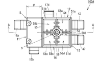
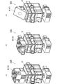
 例えば、図4の例では、仮想線(2点鎖線)で示すように、突起57と突起47の中心間を結んだ線分を対角線とし回動軸3に平行な縦辺を有する第2長方形R2の縦辺の長さd3は5Pであり、横辺の長さd4はPである。
In addition, the protrusions 47 or recesses 48e to 48f on the side surface of the rotation block 4 and the protrusions 57 or recesses 58e to 58f on the side surface of the floating block 5 are aligned with each other when viewed from the connection direction. The second rectangle R2 having a vertical side parallel to the rotation axis with the line segment connecting the centers thereof as a diagonal line is formed so that the vertical side and the horizontal knitting are an integral multiple of P.
For example, in the example of FIG. 4, as indicated by a virtual line (two-dot chain line), a second rectangle having a vertical side parallel to the rotation axis 3 with a line segment connecting the centers of the protrusions 57 and 47 as a diagonal line. The length d3 of the vertical side of R2 is 5P, and the length d4 of the horizontal side is P.
 回動ブロック4、及び遊動ブロック5の側面と、ブロック本体1の回動軸3に平行な面は、同方向に向けて回動軸3に平行な方向から見た際の距離がPの整数倍に形成されている。例えば、図6の例では、遊動ブロック5の側面53,54,56と、ブロック本体1の面13,14,12は、距離が0(Pの0倍)であり、側面55と面11の距離はPである。回動ブロック4の外面41と遊動ブロックの外面51の距離もPの整数倍に形成されており、図2の例では、6Pである。また、回動ブロック4の側面43~46と遊動ブロック5の側面53~56は、同方向に向けた際に面一となるよう形成されている。回動ブロック4の側面43~46と遊動ブロック5の側面53~56とを面一にならないようにする場合は、同方向に向けた際の回動軸3に平行な方向から見た距離がPの整数倍に形成されることが好ましい。 The side surfaces of the rotation block 4 and the floating block 5 and the surface parallel to the rotation axis 3 of the block body 1 are integers having a distance P when viewed from the direction parallel to the rotation axis 3 in the same direction. It is formed twice. For example, in the example of FIG. 6, the distance between the side surfaces 53, 54, and 56 of the floating block 5 and the surfaces 13, 14, and 12 of the block body 1 is 0 (0 times P). The distance is P. The distance between the outer surface 41 of the rotating block 4 and the outer surface 51 of the floating block is also an integral multiple of P, and is 6P in the example of FIG. Further, the side surfaces 43 to 46 of the rotating block 4 and the side surfaces 53 to 56 of the floating block 5 are formed to be flush with each other when facing in the same direction. When the side surfaces 43 to 46 of the rotating block 4 and the side surfaces 53 to 56 of the floating block 5 are not flush with each other, the distance seen from the direction parallel to the rotating shaft 3 when facing in the same direction is It is preferable to form an integral multiple of P.
 次に、サーボモータ付組立ブロック100の作用について説明する。
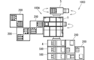
 図9に、組立ブロックキット1000を用いて作成した組立例1001を示す。組立例1001では、組立ブロック200、300により、ブロック本体1と遊動ブロック5が連結固定されているため、サーボモータ2を駆動させると、静止したブロック本体1及び遊動ブロック5に対し回動ブロック4のみが回動する。
Next, the operation of the assembly block 100 with servo motor will be described.
FIG. 9 shows an assembly example 1001 created using the assembly block kit 1000. In the assembly example 1001, the block main body 1 and the idle block 5 are connected and fixed by the assembly blocks 200 and 300. Therefore, when the servo motor 2 is driven, the rotation block 4 is moved with respect to the stationary block main body 1 and the idle block 5. Only turn.
 サーボモータ付組立ブロック100では、ブロック本体1の突起17a~17dと遊動ブロック5の側面の突起57や凹部58e~58hは、第1長方形の縦辺及び横辺が整数倍に設けられ、かつ遊動ブロック4の側面53~56とブロック本体1の面11~14を同方向に向けたときの距離が、Pの整数倍に形成されているため、組立例1001のように、基本ブロック200~700により連結することができる。 In the assembly block 100 with the servo motor, the protrusions 17a to 17d of the block body 1, the protrusions 57 and the recesses 58e to 58h on the side surface of the floating block 5 are provided with an integer multiple of the vertical and horizontal sides of the first rectangle. Since the distance when the side surfaces 53 to 56 of the block 4 and the surfaces 11 to 14 of the block body 1 are directed in the same direction is formed to be an integral multiple of P, the basic blocks 200 to 700 are as in the assembly example 1001. Can be linked together.
 図10は、組立ブロックキット1000により組立てた組立例1002を示している。組立例1002では、回動ブロック4、及び遊動ブロック5が基本ブロック500,600により互いに連結固定されているため、サーボモータ2を駆動させると、静止した回動ブロック4及び遊動ブロック5に対してブロック本体1が、図10に矢印で示したように回動する。また、このように回動ブロック4と遊動ブロック5の両方を固定する場合に、回動ブロック4と遊動ブロック5とが互いに回動自在であるため、当該両ブロック4,5は互いに拘束されずに好きな方向に向けて他の組立ブロックに固定することができる。 FIG. 10 shows an assembly example 1002 assembled by the assembly block kit 1000. In the assembly example 1002, the rotation block 4 and the idle block 5 are connected and fixed to each other by the basic blocks 500 and 600. Therefore, when the servo motor 2 is driven, the stationary block 4 and the idle block 5 are stationary. The block body 1 rotates as indicated by the arrows in FIG. In addition, when both the rotating block 4 and the floating block 5 are fixed in this way, the rotating block 4 and the floating block 5 are rotatable with respect to each other, so that the blocks 4 and 5 are not restricted to each other. It can be fixed to other assembly blocks in the desired direction.
 サーボモータ付組立ブロック100では、外面43,53だけでなく、側面43~46,53~56に凹部や突起を有するため、組立ブロックを多様な形状に組み立てることができるばかりでなく回転の様子も多様になり、形状の多様さと回転の様子の多様さが相俟って、より多様な形態の作品を楽しむことができる。また、回動軸3の軸心方向に位置する他の組立ブロックにも回動軸3に垂直な方向に位置する他の組立ブロックにも直接回動ブロック4や遊動ブロック5を連結できる。
 また、回動ブロック4の突起47、又は凹部48e~48hと遊動ブロック57の突起57又は凹部58e~58hは、第2長方形の縦辺、及び横編が、ともにPの整数倍に形成され、回動ブロック4の側面43~46と遊動ブロック5の側面53~56が面一になるよう形成されているため、基本ブロック200~700で連結することができる。
In the assembly block 100 with servo motor, not only the outer surfaces 43 and 53 but also the side surfaces 43 to 46 and 53 to 56 are provided with recesses and protrusions, so that the assembly block can be assembled into various shapes and also rotated. Diversified, the variety of shapes and the variety of the state of rotation combined, you can enjoy more diverse forms of work. Further, the rotation block 4 and the idle block 5 can be directly connected to other assembly blocks positioned in the axial direction of the rotation shaft 3 and to other assembly blocks positioned in a direction perpendicular to the rotation shaft 3.
Further, the protrusion 47 or the recesses 48e to 48h of the rotating block 4 and the protrusion 57 or the recesses 58e to 58h of the floating block 57 are formed so that the vertical side and the horizontal knitting of the second rectangle are both integral multiples of P. Since the side surfaces 43 to 46 of the rotating block 4 and the side surfaces 53 to 56 of the floating block 5 are formed to be flush with each other, the basic blocks 200 to 700 can be connected.
図11は、組立ブロックキット1000により組立てた組立例1003を示している。組立例1003では、組立ブロック200,500により組まれた基台に、回動ブロック4のみが固定されているため、サーボモータ2を駆動させると、静止した回動ブロック4に対し、ブロック本体1、及び遊動ブロック5が回動する。 FIG. 11 shows an assembly example 1003 assembled by the assembly block kit 1000. In the assembly example 1003, since only the rotation block 4 is fixed to the base assembled by the assembly blocks 200 and 500, when the servo motor 2 is driven, the block main body 1 with respect to the stationary rotation block 4 is fixed. , And the floating block 5 rotates.
 ブロック本体1の第3面13に組立ブロック200~800を結合する場合は、図12に示すように、電気配線7を切欠き部18aや19aに収容することで、第3面13に結合する基本ブロックをリブ18及び19に隙間なく当接させることができる。 When the assembly blocks 200 to 800 are coupled to the third surface 13 of the block body 1, as shown in FIG. 12, the electrical wiring 7 is accommodated in the notches 18a and 19a to be coupled to the third surface 13. The basic block can be brought into contact with the ribs 18 and 19 without any gap.
 本発明は、上記の実施形態に限らず、例えば、サーボモータ付組立ブロックは、図13(a)に示したサーボモータ付組立ブロック100Bのように、回動ブロック4のみを有し、遊動ブロックを有さなくともよいし、図13(b)に示したサーボモータ付組立ブロック100Cのように、回動軸とともに回動する回動ブロック4を2つ備えてもよい。 The present invention is not limited to the above-described embodiment. For example, the assembly block with a servo motor includes only the rotation block 4 as in the assembly block 100B with a servo motor shown in FIG. There may be two rotation blocks 4 that rotate together with the rotation shaft as in the assembly block 100C with servo motor shown in FIG. 13 (b).
 また、回動ブロックは、上述した形状に限らず図14に符号4D,4E,4Fで示したように、また、遊動ブロックも5D,5E,5Fで示したように、各種の形状を用いることができる。ブロック本体は、直方体に限らず、本発明の趣旨を逸脱しない範囲において、直方体や三角柱等の多面体の他、公知の立体形状を適宜採用できる。ブロック本体には、突起の代わりに凹部を設けてもよいし、突起と凹部の両方を設けてもよい。 Further, the rotating block is not limited to the shape described above, and various shapes are used as indicated by reference numerals 4D, 4E, and 4F in FIG. 14, and the floating block is also indicated by 5D, 5E, and 5F. Can do. The block body is not limited to a rectangular parallelepiped, and a known three-dimensional shape can be appropriately employed in addition to a polyhedron such as a rectangular parallelepiped or a triangular prism within a range not departing from the gist of the present invention. The block body may be provided with a recess instead of the protrusion, or may be provided with both a protrusion and a recess.
1 ブロック本体
17a,17b,17c,17d 突起(連結手段)
2 サーボモータ
3 回動軸
4,4D,4E,4F 回動ブロック
41 外面
42 内面
43,44,45,46 側面
47 突起(連結手段)
48a,48b,48c,48d,48e,48f,48g,48h,48D,48E,48F 凹部(連結手段)
5,5D,5E,5F 遊動ブロック
51 外面
52 内面
53,54,55,56 側面
57 突起(連結手段)
58a,58b,58c,58d,58e,58f,58g,58h,58D,58E,58F 凹部(連結手段)
100A,100B,100C,100D,100E,100F サーボモータ付組立ブロック
200,300,400,500,600,700 基本ブロック
207,307,407,507,607,707,807 突起
208,308,408,508,608,708,808 凹部
1000 組立ブロックキット
1 Block body 17a, 17b, 17c, 17d Protrusion (connecting means)
2 Servo motor 3 Rotating shaft 4, 4D, 4E, 4F Rotating block 41 Outer surface 42 Inner surface 43, 44, 45, 46 Side surface 47 Projection (connecting means)
48a, 48b, 48c, 48d, 48e, 48f, 48g, 48h, 48D, 48E, 48F Recessed portion (connecting means)
5, 5D, 5E, 5F Floating block 51 Outer surface 52 Inner surface 53, 54, 55, 56 Side surface 57 Projection (connection means)
58a, 58b, 58c, 58d, 58e, 58f, 58g, 58h, 58D, 58E, 58F Recessed portion (connecting means)
100A, 100B, 100C, 100D, 100E, 100F Assembly block with servo motor 200, 300, 400, 500, 600, 700 Basic block 207, 307, 407, 507, 607, 707, 807 Projection 208, 308, 408, 508 , 608, 708, 808 Recess 1000 Assembly block kit

Claims (6)

  1.  表面に突起、又は凹部からなる連結手段を少なくとも1つ有するブロック本体と、前記ブロック本体に設けられるサーボモータと、前記サーボモータにより回転駆動される回動軸と、を有し、前記連結手段を他の組立ブロックの突起、又は凹部からなる連結手段に嵌合させることにより、前記他の組立ブロックに結合可能なサーボモータ付組立ブロックであって、
     前記回動軸の一端部に固定されて前記回動軸とともに回動する回動ブロックを備え、
     前記回動ブロックは、多面体からなり、表面に凹部、又は突起からなる連結手段を有することを特徴とするサーボモータ付組立ブロック。
    A block main body having at least one connecting means comprising a protrusion or a recess on the surface; a servo motor provided on the block main body; and a rotation shaft that is rotationally driven by the servo motor. An assembly block with a servo motor that can be coupled to the other assembly block by being fitted to a connecting means comprising a protrusion or a recess of the other assembly block,
    A rotation block fixed to one end of the rotation shaft and rotated together with the rotation shaft;
    The assembly block with a servo motor, wherein the rotation block is formed of a polyhedron and has a connecting means including a recess or a protrusion on the surface.
  2.  前記回動ブロックは、前記回動軸に平行な側面を少なくとも1つ備え、当該側面に少なくとも1つの連結手段を有する請求項1に記載のサーボモータ付組立ブロック。 2. The assembly block with a servo motor according to claim 1, wherein the rotation block includes at least one side surface parallel to the rotation axis, and has at least one connecting means on the side surface.
  3.  多面体からなり、表面に突起、又は凹部からなる連結手段を有し、前記回動軸の他端側の延長線回りに回動するよう前記ブロック本体に軸支される遊動ブロックを備え、
     前記遊動ブロックは、前記ブロック本体、及び前記回動軸から独立して回動する請求項1に記載のサーボモータ付組立ブロック。
    It comprises a polyhedron, has a connecting means consisting of a protrusion or a recess on the surface, and includes a floating block that is pivotally supported by the block body so as to rotate around an extension line on the other end side of the rotating shaft,
    The assembly block with a servo motor according to claim 1, wherein the floating block rotates independently from the block main body and the rotation shaft.
  4.  前記遊動ブロックは、前記回動軸に平行な少なくとも1つの側面を備え、当該側面に少なくとも1つの連結手段を有する請求項3に記載のサーボモータ付組立ブロック。 4. The assembly block with a servo motor according to claim 3, wherein the idle block has at least one side surface parallel to the rotation shaft and has at least one connecting means on the side surface.
  5.  直方体をなし表面に突起と凹部を少なくとも1つずつ含む連結手段を備えた基本ブロックと、
     請求項4に記載のサーボモータ付組立ブロックと、を備え、
     前記基本ブロックは、各面が1辺の長さをPとする正方形の区分を一又は複数個並べた長方形からなり、
     前記基本ブロックの連結手段は、前記区分の中央に設けられ、非対向の2つの区分のそれぞれに設けられる突起と凹部を少なくとも1組含み、
     前記サーボモータ付組立ブロックの連結手段は、前記基本ブロックの突起又は凹部に嵌合可能に形成されるとともに、前記ブロック本体の連結手段は、前記回動軸に垂直な連結方向を有しており、
     前記遊動ブロックの側面の連結手段は、突起と凹部を少なくとも1つずつ含み、
     前記ブロック本体の連結手段と、前記遊動ブロックの側面の連結手段の連結方向を一致させて連結方向に平行に見た際に、前記ブロック本体の連結手段と、前記遊動ブロック側面の連結手段の中心間を結んだ線分を対角線とし、前記回動軸に平行な縦辺を有する長方形の縦辺及び横編がともにPの整数倍に形成されている組立ブロックキット。
    A basic block having a rectangular parallelepiped and provided with connecting means including at least one protrusion and a recess on the surface;
    An assembly block with a servo motor according to claim 4,
    The basic block consists of a rectangle in which one or a plurality of square sections each having a side P of one side are arranged,
    The connecting means of the basic block is provided at the center of the section, and includes at least one set of protrusions and recesses provided in each of the two non-opposing sections,
    The connecting means of the assembly block with servo motor is formed so as to be able to fit into the protrusion or recess of the basic block, and the connecting means of the block body has a connecting direction perpendicular to the rotating shaft. ,
    The connecting means on the side surface of the floating block includes at least one protrusion and one recess,
    When the connecting means of the block main body and the connecting means of the side surface of the floating block are aligned and viewed in parallel with the connecting direction, the connecting means of the block main body and the center of the connecting means of the side surface of the floating block An assembly block kit in which a line segment connecting the diagonal lines is a diagonal line, and a rectangular vertical side and a horizontal knitting having a vertical side parallel to the rotation axis are both formed to be an integral multiple of P.
  6.  直方体をなし表面に突起と凹部を少なくとも1つずつ含む連結手段を備えた基本ブロックと、
     請求項4に記載のサーボモータ付組立ブロックと、を備え、
    前記基本ブロックは、各面が1辺の長さをPとする正方形の区分を一又は複数個並べた長方形からなり、
     前記基本ブロックの連結手段は、前記区分の中央に設けられ、非対向の2つの区分のそれぞれに設けられる突起と凹部を少なくとも1組含み、
     前記サーボモータ付組立ブロックの連結手段は、前記基本ブロックの突起又は凹部に嵌合可能に形成されており、
     前記回動ブロックの側面及び前記遊動ブロックの側面の連結手段は、何れも突起と凹部を少なくとも1つずつ含み、
     前記回動ブロックの側面の連結手段と、前記遊動ブロックの側面の連結手段の連結方向を一致させて連結方向に平行に見た際に、前記回動ブロックの連結手段と、前記遊動ブロック側面の連結手段の中心間を結んだ線分を対角線とし、前記回動軸に平行な縦辺を有する長方形の縦辺及び横編がともにPの整数倍に形成されている組立ブロックキット。
    A basic block having a rectangular parallelepiped and provided with connecting means including at least one protrusion and a recess on the surface;
    An assembly block with a servo motor according to claim 4,
    The basic block consists of a rectangle in which one or a plurality of square sections each having a side P of one side are arranged,
    The connecting means of the basic block is provided at the center of the section, and includes at least one set of protrusions and recesses provided in each of the two non-opposing sections,
    The connecting means of the assembly block with servo motor is formed so as to be able to fit into the protrusion or recess of the basic block,
    Each of the connecting means of the side surface of the rotating block and the side surface of the floating block includes at least one protrusion and a recess,
    When the connecting means of the side surface of the rotating block and the connecting means of the side surface of the floating block are aligned and viewed in parallel with the connecting direction, the connecting means of the rotating block and the side surface of the floating block An assembly block kit in which a line segment connecting the centers of connecting means is a diagonal line, and a rectangular vertical side and a horizontal knitting each having a vertical side parallel to the rotation axis are formed to be an integral multiple of P.
PCT/JP2014/059463 2014-03-31 2014-03-31 Assembly block with servomotor, and assembly block kit WO2015151161A1 (en)

Priority Applications (9)

Application Number Priority Date Filing Date Title
PL14888480T PL3127588T3 (en) 2014-03-31 2014-03-31 Assembly block with servomotor, and assembly block kit
JP2014561633A JP6039702B2 (en) 2014-03-31 2014-03-31 Assembly block with servo motor and assembly block kit
SG11201607868QA SG11201607868QA (en) 2014-03-31 2014-03-31 Assembly block with servomotor, and assembly block kit
EP14888480.2A EP3127588B1 (en) 2014-03-31 2014-03-31 Assembly block with servomotor, and assembly block kit
CN201480075133.3A CN106102853B (en) 2014-03-31 2014-03-31 Assembling building blocks with servo motor and assembling toy building set
PCT/JP2014/059463 WO2015151161A1 (en) 2014-03-31 2014-03-31 Assembly block with servomotor, and assembly block kit
KR1020167023719A KR102087772B1 (en) 2014-03-31 2014-03-31 Assembly block with servomotor, and assembly block kit
ES14888480T ES2752126T3 (en) 2014-03-31 2014-03-31 Mounting block with servo motor, and mounting block kit
US15/279,623 US10124269B2 (en) 2014-03-31 2016-09-29 Assembly block with servomotor, and assembly block kit

Applications Claiming Priority (1)

Application Number Priority Date Filing Date Title
PCT/JP2014/059463 WO2015151161A1 (en) 2014-03-31 2014-03-31 Assembly block with servomotor, and assembly block kit

Related Child Applications (1)

Application Number Title Priority Date Filing Date
US15/279,623 Continuation US10124269B2 (en) 2014-03-31 2016-09-29 Assembly block with servomotor, and assembly block kit

Publications (1)

Publication Number Publication Date
WO2015151161A1 true WO2015151161A1 (en) 2015-10-08

Family

ID=54239532

Family Applications (1)

Application Number Title Priority Date Filing Date
PCT/JP2014/059463 WO2015151161A1 (en) 2014-03-31 2014-03-31 Assembly block with servomotor, and assembly block kit

Country Status (9)

Country Link
US (1) US10124269B2 (en)
EP (1) EP3127588B1 (en)
JP (1) JP6039702B2 (en)
KR (1) KR102087772B1 (en)
CN (1) CN106102853B (en)
ES (1) ES2752126T3 (en)
PL (1) PL3127588T3 (en)
SG (1) SG11201607868QA (en)
WO (1) WO2015151161A1 (en)

Cited By (1)

* Cited by examiner, † Cited by third party
Publication number Priority date Publication date Assignee Title
CN105879407A (en) * 2016-06-30 2016-08-24 上海未来伙伴机器人有限公司 Building block kit

Families Citing this family (5)

* Cited by examiner, † Cited by third party
Publication number Priority date Publication date Assignee Title
US10410738B2 (en) * 2016-03-15 2019-09-10 Toshiba Memory Corporation Memory system and control method
US10668398B2 (en) * 2018-10-30 2020-06-02 Joel Allen Schulz Curiosity revealing or animating a shaped cavity
CN112233532B (en) * 2020-10-09 2022-03-22 安阳大诺科教器材有限公司 Model building system and building method with motor power
USD972510S1 (en) * 2021-03-25 2022-12-13 Lego A/S Motor
IT202100008699A1 (en) * 2021-04-09 2022-10-09 Paolo Caviglia INTERLOCKING INSERT FOR INSERTING ELECTROMECHANICAL AND ELECTRONIC COMPONENTS OF CURRENT COMMERCIAL PRODUCTION INTO CONSTRUCTIONS MADE WITH INTERLOCKING BUILDING BLOCKS, BETTER KNOWN AS 'PLASTIC BRICKS'

Citations (6)

* Cited by examiner, † Cited by third party
Publication number Priority date Publication date Assignee Title
JPS6368190A (en) * 1986-08-04 1988-03-28 ファンタジー・トイズ・インコーポレーテッド Rotary assembly with wheel for assembling block
JPH0425797U (en) * 1990-06-26 1992-02-28
US5738558A (en) * 1997-02-05 1998-04-14 Connector Set Limited Partnership Motor for toy construction system
US6561866B1 (en) * 1999-09-03 2003-05-13 Jeong Min Lee Moveable and sectional block toy
JP2008161350A (en) * 2006-12-27 2008-07-17 Tomy Co Ltd Robot toy and assembling method thereof
WO2013118238A1 (en) * 2012-02-06 2013-08-15 株式会社アーテック Connectable block

Family Cites Families (36)

* Cited by examiner, † Cited by third party
Publication number Priority date Publication date Assignee Title
DK116984B (en) * 1966-05-20 1970-03-02 Fischer Artur Motor housing for construction toys.
FR96379E (en) * 1968-08-03 1972-06-16 Fischer Artur Motor for toys.
GB1299019A (en) * 1969-11-24 1972-12-06 Tomy Kogyo Co Toy construction set
DE2807429A1 (en) * 1978-02-22 1979-08-30 Fischer Artur Dr H C PLAY COMPONENT WITH GROOVED AND / OR BAR-SHAPED FASTENERS
DE2846666A1 (en) * 1978-10-26 1980-05-08 August Mayr COMPONENT SET FOR GAME PURPOSES
ES8502346A1 (en) * 1983-03-30 1985-01-01 Mawdsley Brian Toys or models.
AR242503A1 (en) 1986-07-21 1993-04-30 Lego As Toy centre-rail railway, and a locomotive to run on the system.
US4813903A (en) * 1986-09-23 1989-03-21 Tomy Kogyo Co., Inc. Block toy with integral drive shaft
JP2523165B2 (en) 1988-09-01 1996-08-07 富士通株式会社 Servo control device for optical disk
DE4030119A1 (en) * 1990-09-24 1992-03-26 Uwe Kochanneck MULTIBLOCK ROBOT
US5346420A (en) * 1990-12-11 1994-09-13 Connector Set Limited Partnership Gearing and drive mechanism for construction toy system
US5259803A (en) * 1991-04-09 1993-11-09 Lyman Ronald L Toy construction set featuring gears and radiant connectors
JPH0691062A (en) * 1992-09-16 1994-04-05 Sankyo Seiki Mfg Co Ltd Block unit for block toy
JPH0761382A (en) 1993-08-23 1995-03-07 Bridgestone Corp Division type rubber crawler core and end part fixing structure of steel cord
DE19517852A1 (en) * 1995-05-16 1995-12-14 Uwe Kochanneck Multi-unit robotic system with addn. of standard parts
JP3827253B2 (en) 1996-10-09 2006-09-27 株式会社システムワット Assembly block and assembly toy system
US6636781B1 (en) * 2001-05-22 2003-10-21 University Of Southern California Distributed control and coordination of autonomous agents in a dynamic, reconfigurable system
US6679780B1 (en) * 2002-10-18 2004-01-20 Sywan-Min Shih Polyomino piece for games
US6893316B2 (en) * 2003-05-08 2005-05-17 Mattel, Inc. Toys with mechanical interaction and method of using the same
DK200401612A (en) * 2004-10-20 2006-04-21 Lego As Toy building system with functional blocks
JP4378661B2 (en) * 2007-11-20 2009-12-09 コクヨ株式会社 Assembled toy
JP4397412B2 (en) * 2007-12-07 2010-01-13 株式会社タカラトミー Robot toy and its assembly method
US9550130B2 (en) * 2008-03-28 2017-01-24 Robotzone, Llc Kits and components for modular hobby mechanical and robotic construction
US9472112B2 (en) * 2009-07-24 2016-10-18 Modular Robotics Incorporated Educational construction modular unit
DE102010062217B4 (en) * 2010-01-22 2018-11-22 Kinematics Gmbh Modular system with movable modules
CN202223903U (en) * 2011-06-03 2012-05-23 广州迪宝乐电子有限公司 Digital electric building blocks
US8888552B2 (en) * 2011-09-15 2014-11-18 Jakks Pacific, Inc. Twistable and connectable block
WO2013066901A1 (en) * 2011-10-31 2013-05-10 Modular Robotics Incorporated Modular kinematic construction kit
US20160361662A1 (en) * 2012-02-17 2016-12-15 Technologyone, Inc. Interactive lcd display back light and triangulating toy brick baseplate
CA2847378A1 (en) * 2012-02-17 2013-08-22 Technology One, Inc. Baseplate assembly for use with toy pieces
US20130217294A1 (en) * 2012-02-17 2013-08-22 Arjuna Ragunath Karunaratne Toy brick with sensing, actuation and control
KR20150089192A (en) * 2014-01-27 2015-08-05 유니트러스트개발(주) Power train system and built-up type toy having this
BR112016025599B1 (en) * 2014-05-15 2022-11-08 Lego A/S TOY BUILDING SYSTEM AND FUNCTION BUILDING ELEMENT FOR A TOY BUILDING SYSTEM
US20170173485A1 (en) * 2015-02-12 2017-06-22 Geeknet, Inc. Reconfigurable brick building system and structure
CN204798858U (en) 2015-05-21 2015-11-25 李本胜 But ring, wedge plug -in type wood chip
JP6205540B1 (en) 2017-01-27 2017-09-27 水川 裕雄 Freshly assembled toys

Patent Citations (6)

* Cited by examiner, † Cited by third party
Publication number Priority date Publication date Assignee Title
JPS6368190A (en) * 1986-08-04 1988-03-28 ファンタジー・トイズ・インコーポレーテッド Rotary assembly with wheel for assembling block
JPH0425797U (en) * 1990-06-26 1992-02-28
US5738558A (en) * 1997-02-05 1998-04-14 Connector Set Limited Partnership Motor for toy construction system
US6561866B1 (en) * 1999-09-03 2003-05-13 Jeong Min Lee Moveable and sectional block toy
JP2008161350A (en) * 2006-12-27 2008-07-17 Tomy Co Ltd Robot toy and assembling method thereof
WO2013118238A1 (en) * 2012-02-06 2013-08-15 株式会社アーテック Connectable block

Non-Patent Citations (2)

* Cited by examiner, † Cited by third party
Title
"Catalog that was distributed by International Tokyo Toy Show 2013", ARTEC BLOCK SEIHIN CATALOG, ARTEC, 13 June 2013 (2013-06-13), pages 5, XP008185864 *
"Servomotor (3kg·cm", ARTEC BLOCK ROBO GA TV DE SHOKAI SAREMASHITA - YOUTUBE, 14 November 2013 (2013-11-14), XP054976214, Retrieved from the Internet <URL:http://www.youtube.com/watch?v=G8_eaKoGNA8> [retrieved on 20140609] *

Cited By (1)

* Cited by examiner, † Cited by third party
Publication number Priority date Publication date Assignee Title
CN105879407A (en) * 2016-06-30 2016-08-24 上海未来伙伴机器人有限公司 Building block kit

Also Published As

Publication number Publication date
KR20170009815A (en) 2017-01-25
JP6039702B2 (en) 2016-12-07
CN106102853B (en) 2019-07-16
SG11201607868QA (en) 2016-11-29
US10124269B2 (en) 2018-11-13
CN106102853A (en) 2016-11-09
JPWO2015151161A1 (en) 2017-04-13
KR102087772B1 (en) 2020-03-11
EP3127588B1 (en) 2019-08-28
EP3127588A4 (en) 2018-01-17
US20170014726A1 (en) 2017-01-19
EP3127588A1 (en) 2017-02-08
PL3127588T3 (en) 2020-03-31
ES2752126T3 (en) 2020-04-03

Similar Documents

Publication Publication Date Title
WO2015151161A1 (en) Assembly block with servomotor, and assembly block kit
US6238264B1 (en) Walking apparatus
WO2013118238A1 (en) Connectable block
KR101259759B1 (en) Omni-directional Wheel And Manufacturing Method Thereof
KR20070066182A (en) A block toy
CN104768716A (en) Actuator assembly
KR20170028809A (en) Junction Member of Assembly Toys
JP6922654B2 (en) Vehicle grill shutter device
KR100554384B1 (en) The solid puzzle block
KR20080019360A (en) One-block assembly blocks
CN217448935U (en) Modular building block driving base
CN103908786A (en) Assembly building block component and toy
KR19990078845A (en) Block toy
JP2007181588A (en) Block toy
KR200469542Y1 (en) Magentic block toy with joint module
JP2001224866A (en) Walker
KR20200097980A (en) Assembled toys
US11025132B2 (en) Case for a servomotor
CN219595155U (en) Massage machine core
KR200332361Y1 (en) Motor box for toy
KR20200025911A (en) Gear-powered toys
KR20130040967A (en) Block toys for children for the development of creativity and brain development
KR20210071512A (en) gjajl gka tkakeksad dfdafeqrdf dfadaff aadfafa aafdfaf adadfaf eredr
KR20040015429A (en) Toy Crab Being Operated with Cam Structure
KR20050053258A (en) Toy chain block

Legal Events

Date Code Title Description
ENP Entry into the national phase

Ref document number: 2014561633

Country of ref document: JP

Kind code of ref document: A

121 Ep: the epo has been informed by wipo that ep was designated in this application

Ref document number: 14888480

Country of ref document: EP

Kind code of ref document: A1

ENP Entry into the national phase

Ref document number: 20167023719

Country of ref document: KR

Kind code of ref document: A

REEP Request for entry into the european phase

Ref document number: 2014888480

Country of ref document: EP

WWE Wipo information: entry into national phase

Ref document number: 2014888480

Country of ref document: EP

NENP Non-entry into the national phase

Ref country code: DE