WO2015149840A1 - Refrigeration appliance provided with an improved defrost circuit - Google Patents
Refrigeration appliance provided with an improved defrost circuit Download PDFInfo
- Publication number
- WO2015149840A1 WO2015149840A1 PCT/EP2014/056457 EP2014056457W WO2015149840A1 WO 2015149840 A1 WO2015149840 A1 WO 2015149840A1 EP 2014056457 W EP2014056457 W EP 2014056457W WO 2015149840 A1 WO2015149840 A1 WO 2015149840A1
- Authority
- WO
- WIPO (PCT)
- Prior art keywords
- evaporator
- refrigerant
- circuit line
- compressor
- defrost
- Prior art date
- Legal status (The legal status is an assumption and is not a legal conclusion. Google has not performed a legal analysis and makes no representation as to the accuracy of the status listed.)
- Ceased
Links
Images


Classifications
-
- F—MECHANICAL ENGINEERING; LIGHTING; HEATING; WEAPONS; BLASTING
- F25—REFRIGERATION OR COOLING; COMBINED HEATING AND REFRIGERATION SYSTEMS; HEAT PUMP SYSTEMS; MANUFACTURE OR STORAGE OF ICE; LIQUEFACTION SOLIDIFICATION OF GASES
- F25B—REFRIGERATION MACHINES, PLANTS OR SYSTEMS; COMBINED HEATING AND REFRIGERATION SYSTEMS; HEAT PUMP SYSTEMS
- F25B47/00—Arrangements for preventing or removing deposits or corrosion, not provided for in another subclass
- F25B47/02—Defrosting cycles
- F25B47/022—Defrosting cycles hot gas defrosting
-
- F—MECHANICAL ENGINEERING; LIGHTING; HEATING; WEAPONS; BLASTING
- F25—REFRIGERATION OR COOLING; COMBINED HEATING AND REFRIGERATION SYSTEMS; HEAT PUMP SYSTEMS; MANUFACTURE OR STORAGE OF ICE; LIQUEFACTION SOLIDIFICATION OF GASES
- F25B—REFRIGERATION MACHINES, PLANTS OR SYSTEMS; COMBINED HEATING AND REFRIGERATION SYSTEMS; HEAT PUMP SYSTEMS
- F25B41/00—Fluid-circulation arrangements
- F25B41/30—Expansion means; Dispositions thereof
- F25B41/39—Dispositions with two or more expansion means arranged in series, i.e. multi-stage expansion, on a refrigerant line leading to the same evaporator
-
- F—MECHANICAL ENGINEERING; LIGHTING; HEATING; WEAPONS; BLASTING
- F25—REFRIGERATION OR COOLING; COMBINED HEATING AND REFRIGERATION SYSTEMS; HEAT PUMP SYSTEMS; MANUFACTURE OR STORAGE OF ICE; LIQUEFACTION SOLIDIFICATION OF GASES
- F25B—REFRIGERATION MACHINES, PLANTS OR SYSTEMS; COMBINED HEATING AND REFRIGERATION SYSTEMS; HEAT PUMP SYSTEMS
- F25B2400/00—Component parts or details not otherwise provided for in this subclass
- F25B2400/04—Refrigeration circuit bypassing means
- F25B2400/0403—Refrigeration circuit bypassing means for condensers
-
- F—MECHANICAL ENGINEERING; LIGHTING; HEATING; WEAPONS; BLASTING
- F25—REFRIGERATION OR COOLING; COMBINED HEATING AND REFRIGERATION SYSTEMS; HEAT PUMP SYSTEMS; MANUFACTURE OR STORAGE OF ICE; LIQUEFACTION SOLIDIFICATION OF GASES
- F25B—REFRIGERATION MACHINES, PLANTS OR SYSTEMS; COMBINED HEATING AND REFRIGERATION SYSTEMS; HEAT PUMP SYSTEMS
- F25B2400/00—Component parts or details not otherwise provided for in this subclass
- F25B2400/04—Refrigeration circuit bypassing means
- F25B2400/0411—Refrigeration circuit bypassing means for expansion valves or capillary tubes
-
- F—MECHANICAL ENGINEERING; LIGHTING; HEATING; WEAPONS; BLASTING
- F25—REFRIGERATION OR COOLING; COMBINED HEATING AND REFRIGERATION SYSTEMS; HEAT PUMP SYSTEMS; MANUFACTURE OR STORAGE OF ICE; LIQUEFACTION SOLIDIFICATION OF GASES
- F25B—REFRIGERATION MACHINES, PLANTS OR SYSTEMS; COMBINED HEATING AND REFRIGERATION SYSTEMS; HEAT PUMP SYSTEMS
- F25B5/00—Compression machines, plants or systems, with several evaporator circuits, e.g. for varying refrigerating capacity
- F25B5/04—Compression machines, plants or systems, with several evaporator circuits, e.g. for varying refrigerating capacity arranged in series
-
- F—MECHANICAL ENGINEERING; LIGHTING; HEATING; WEAPONS; BLASTING
- F25—REFRIGERATION OR COOLING; COMBINED HEATING AND REFRIGERATION SYSTEMS; HEAT PUMP SYSTEMS; MANUFACTURE OR STORAGE OF ICE; LIQUEFACTION SOLIDIFICATION OF GASES
- F25D—REFRIGERATORS; COLD ROOMS; ICE-BOXES; COOLING OR FREEZING APPARATUS NOT OTHERWISE PROVIDED FOR
- F25D11/00—Self-contained movable devices, e.g. domestic refrigerators
- F25D11/02—Self-contained movable devices, e.g. domestic refrigerators with cooling compartments at different temperatures
- F25D11/022—Self-contained movable devices, e.g. domestic refrigerators with cooling compartments at different temperatures with two or more evaporators
Definitions
- the present invention relates to a refrigeration appliance provided with an improved defrost mechanism.
- a closed refrigerant circuit having a compressible refrigerant which flows through a compressor, a condenser, a refrigerant expansion element and an evaporator.
- a refrigerant compressed in the compressor is typically condensed into a liquid by the condenser, and then evaporated in the evaporator.
- the condenser effects transfer of thermal energy from the compressed refrigerant to the ambient air and the evaporator transfers thermal energy from the ambient air in the refrigeration compartment to the compressed refrigerant.
- the compressed refrigerant in the refrigerant circuit is in superheated vapor phase while leaving the compressor. It transforms into the liquid-vapor state in the condenser and then into the liquid state en route to the refrigerant expansion element.
- the refrigerant changes to liquid-vapor phase in the refrigerant expansion element while the pressure thereof is being reduced.
- a refrigeration appliance is usually equipped with a system for automatically defrosting the cooling coil at specified intervals so that the ice accumulated on the cooling coil surface is melted and the resultant water is drained away.
- a system may provide that feeding of the compressed refrigerant to the evaporator is temporarily interrupted and a hot refrigerant is directed to the evaporator to defrost the ice collected on the surfaces thereof. The flow of hot refrigerant to the cooling coil is subsequently stopped and the circulation of compressed refrigerant is continued.
- a serious drawback in association with this lies in that the compressor can be subject to a substantial amount of liquid refrigerant instead of gaseous refrigerant due to the thermal exchange between the hot gas and the frost-covered evaporator. If drawn into the compressor, the condensed refrigerant in the defrosted evaporator can cause danger to the compressor.
- a defrost heater can alternatively be employed to thaw or defrost the ice formed.
- a defrost heater can alternatively be employed to thaw or defrost the ice formed.
- such a unit not only requires electric power expenditure but also causes reduced efficiency due to temperature fluctuations.
- the present invention is devised under the recognition that a defrost system involving no additional complexity and having an effective and efficient defrost performance for defrosting the evaporator surface remains a need.
- EP1334321 discloses a defrosting method for a refrigeration appliance having multiple refrigeration compartments, specifically a fresh food compartment and a freezer compartment, which comprises a fresh food evaporator for cooling the fresh food compartment and a freezer evaporator for cooling the freezer compartment.
- the fresh food evaporator is composed of two separate evaporators namely a first sub-evaporator and a second sub-evaporator. Sub-evaporators are arranged in parallel and both of the sub-evaporators are used sequentially for cooling the fresh-food compartment. This enables continuous cooling of the fresh food compartment and defrosting of the fresh food evaporator concurrently.
- the present invention provides a refrigeration appliance having a defrost system by which the ice formed on the cooling coil surface of the appliance can be efficiently thawed without damaging the compressor. More specifically, the present invention ensures that the liquefying refrigerant as a result of the heat exchange between the same and the evaporator is prevented from reaching the compressor and damage to the same is effectively avoided.
- the present invention therefore provides a refrigeration appliance having a defrost system by which the compressor receives no liquid refrigerant as provided by the characterizing features defined in Claim 1.
- Primary object of the present invention is to provide a refrigeration appliance having a mechanically non-complex defrost system by which the compressor receives no liquid refrigerant.
- the present invention proposes a refrigeration appliance having a refrigeration and defrost circuit, which can be utilized both for cooling food items in a refrigeration compartment by way of circulating a compressed refrigerant and for defrosting a first evaporator by way of circulating a hot refrigerant directly to said first evaporator.
- a compressor, a condenser coil in connection with said compressor, a first refrigerant expansion element and said first evaporator are provided as a closed fluid communication circuit.
- a first cooling line is by-passed when the refrigerant is directly circulated to said first evaporator through a first defrost circuit line and a second cooling line is by-passed when the refrigerant is directed to a second refrigerant expansion element through a second defrost circuit line where its pressure is lowered and circulated through an additional second evaporator disposed serially with said first evaporator.
- a second switching valve selectively connects said first evaporator to the second refrigerant expansion element or to the second evaporator.
- the first cooling and defrost lines can join together to form a single first evaporator line, in this case to be separated into the second cooling circuit line and the second defrost circuit line by the second switching valve, or can continue as separately formed lines within said first evaporator in direction to the second switching valve. Or alternatively, they can be formed as separate lines joining at the inlet of said second evaporator.
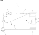
- Fig. 1 demonstrates a general diagram of a refrigeration and defrost circuit according to the present invention.
- Fig. 2 demonstrates a general diagram of a refrigeration and defrost circuit according to the first embodiment of the present invention.
- Fig. 3 demonstrates a general diagram of a refrigeration and defrost circuit according to the second embodiment of the present invention.
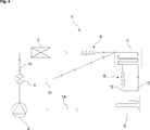
- Fig. 4 demonstrates a general diagram of a refrigeration and defrost circuit according to the third embodiment of the present invention.
- the present invention relates to a refrigeration appliance with at least one refrigeration compartment preserving food items, said appliance further having a compressor (2) compressing a refrigerant to a high temperature and a high pressure, said compressor (2) typically having a suction inlet and a high pressure outlet.
- a condenser coil (3) in connection with said high-pressure outlet of said compressor (2) through a first switching valve (4) is provided to condensate the refrigerant into a liquid.
- a first evaporator (5) evaporating the refrigerant has an inlet connected to a first refrigerant expansion element (6) for example a capillary tube or an expansion valve and an outlet connected to a second switching valve (7).
- the first evaporator (5) typically has a refrigerant flowing pipe and a multitude of plate-shaped fins extending in parallel in an equidistant manner.
- the second switching valve (7) connects the outlet of the first evaporator (5) selectively to a second refrigerant expansion element (8) or to a second evaporator (9).
- the second switching valve (7) therefore controls the flowing direction of the refrigerant as will be delineated in the proceeding section.
- the second evaporator (9) is in turn connected to said compressor (2) through the suction inlet thereof.
- the second evaporator (9) may have the same construction as the first evaporator (5).
- a first cooling circuit line (10) comprises the compressor (2) circulating a compressible refrigerant to a condenser coil (3) in which the refrigerant is condensed into liquid due to transfer of thermal energy from the compressed refrigerant to the ambient air.
- the refrigerant flows through the first refrigerant expansion element (6) in the form of a capillary tube, changing to liquid-vapor phase while its pressure is reduced.
- the refrigerant is then evaporated in the first evaporator (5) due to heat exchange with the air in the at least one refrigeration compartment and returns to the compressor (2) through a compressor return line (14) by passing through the second evaporator (9).
- a first defrost circuit line (11) comprising the compressor (2) circulating a hot refrigerant to the first evaporator (5).
- the refrigerant cools and condenses into liquid state while the first evaporator (5) is defrosted.
- the refrigerant is then directed to the second refrigerant expansion element (8) where its pressure is lowered and circulated through said additional second evaporator (9) serving to the purpose of elevating the temperature of the refrigerant and evaporating the same.
- the first and second switching valves (4, 7) are electrically operated valves realized in the form of solenoid valves. These units are three-way solenoid valves having selectively opening outlets to the first cooling and defrost circuit lines (10, 11) or the second cooling and defrost circuit lines (12, 13) in accordance with the operation mode of the refrigeration and defrost circuit (1). More specifically, the first switching valve (4) selectively allows refrigerant flow in the first cooling circuit line (10) or the first defrost circuit line (11) and the second switching valve (7) selectively allows refrigerant flow in the second cooling circuit line (12) and the second defrost circuit line (13) depending on the operation mode of the refrigeration and defrost circuit (1).
- the first cooling circuit line (10) and the first defrost circuit line (11) may join together to form a single line throughout the first evaporator (5).
- the second switching valve (7) then separates the first evaporator (5) line into the second cooling circuit line (12) and the second defrost circuit line (13).
- the first cooling circuit line (10) and the first defrost circuit line (11) can lead to separate lines within the first evaporator (5) en route to the second switching valve (7).
- the present invention proposes a refrigeration appliance having at least one refrigeration compartment preserving food items, the refrigeration appliance having a refrigeration and defrost circuit (1) comprising a compressor (2) for compressing a refrigerant to a high temperature and a high pressure, a condenser coil (3) in connection with the compressor (2) and in which the refrigerant is condensable into liquid, and a first evaporator (5) in connection with the condenser coil (3) through a first refrigerant expansion element (6), the first evaporator (5) being in fluid communication with the compressor (2) via a compressor return line (14).
- a refrigeration and defrost circuit (1) comprising a compressor (2) for compressing a refrigerant to a high temperature and a high pressure, a condenser coil (3) in connection with the compressor (2) and in which the refrigerant is condensable into liquid, and a first evaporator (5) in connection with the condenser coil (3) through a first refrigerant expansion element (6), the first evapor
- a first defrost circuit line (11) is provided in which a refrigerant is directly circulatable to the first evaporator (5) by the compressor (2) to defrost the first evaporator (5) and a second defrost circuit line (13) is provided in which the refrigerant is directable to a second refrigerant expansion element (8) where its pressure is lowered and circulatable through an additional second evaporator (9) disposed serially with the first evaporator (5).
- the fact that the first and the second evaporators (5, 9) have a serially connected structure completely eliminates the risk of liquid refrigerant flow to the compressor (2) and hence ensures a sound operation.
- a first switching valve (4) selectively allows refrigerant flow in a first cooling circuit line (10) having the condenser coil (3) and the first refrigerant expansion element (6), or the first defrost circuit line (11), depending on the mode of operation of the refrigeration and defrost circuit (1) of the invention.
- a second switching valve (7) connects the first evaporator (5) selectively to the second refrigerant expansion element (8) or to the second evaporator (9).
- the first cooling circuit line (10) and the first defrost circuit line (11) join together to form a single line throughout the first evaporator (5).
- the second switching valve (7) separates the first evaporator (5) line into the second cooling circuit line (12) and the second defrost circuit line (13).
- the first cooling circuit line (10) and the first defrost circuit line (11) lead to separate lines within the first evaporator (5) en route to the second switching valve (7).
- the first cooling circuit line (10) and the first defrost circuit line (11) lead to separate lines within the first evaporator (5) and join together to form a single line at the inlet of the second evaporator (9).
- the present invention therefore affords a refrigeration and defrost circuit by which the ice accumulation problem is addressed so as to be efficiently thaw the ice formed on the cooling coil surface without damaging the compressor (2) and in a mechanically convenient manner, that is, by employing the existing heat exchange components in a conveniently modified manner. More specifically, the present invention ensures that the liquefying refrigerant during the defrost cycle, as a result of the heat exchange between the refrigerant and the evaporator is prevented from returning to the compressor (2) and damage to the same is effectively avoided.
Landscapes
- Engineering & Computer Science (AREA)
- Physics & Mathematics (AREA)
- Mechanical Engineering (AREA)
- Thermal Sciences (AREA)
- General Engineering & Computer Science (AREA)
- Defrosting Systems (AREA)
Abstract
The present invention relates to a refrigeration appliance having at least one refrigeration compartment preserving food items, the refrigeration appliance having a refrigeration and defrost circuit (1) comprising a compressor (2) compressing a refrigerant to a high temperature and a high pressure, a condenser coil (3) in connection with the compressor (2) and in which the refrigerant is condensed into liquid, and a first evaporator (5) in connection with the condenser coil (3) through a first refrigerant expansion element (6), the first evaporator (5) being in fluid communication with the compressor (2) via a compressor return line (14).
Description
The present invention relates to a refrigeration appliance provided with an improved defrost mechanism.
It is known that in a conventional vapor compression system, a closed refrigerant circuit is provided having a compressible refrigerant which flows through a compressor, a condenser, a refrigerant expansion element and an evaporator. A refrigerant compressed in the compressor is typically condensed into a liquid by the condenser, and then evaporated in the evaporator.
The condenser effects transfer of thermal energy from the compressed refrigerant to the ambient air and the evaporator transfers thermal energy from the ambient air in the refrigeration compartment to the compressed refrigerant. The compressed refrigerant in the refrigerant circuit is in superheated vapor phase while leaving the compressor. It transforms into the liquid-vapor state in the condenser and then into the liquid state en route to the refrigerant expansion element. The refrigerant changes to liquid-vapor phase in the refrigerant expansion element while the pressure thereof is being reduced.
Condensation forms due to vapor in the air around the cooling coil having a surface temperature below the freezing point of water. While the cooling coil i.e. the evaporator gradually collects frost to the extent that this condensation freezes, ice builds up on the evaporator surface. Ice being a relatively good heat insulator, ice and frost accumulation on the evaporator surface should be prevented and the build-up of frost should be removed to maintain the ability of the evaporator to transfer thermal energy as well as to ensure the efficient operation of the refrigeration appliance.
In this regard, a refrigeration appliance is usually equipped with a system for automatically defrosting the cooling coil at specified intervals so that the ice accumulated on the cooling coil surface is melted and the resultant water is drained away. Such a system may provide that feeding of the compressed refrigerant to the evaporator is temporarily interrupted and a hot refrigerant is directed to the evaporator to defrost the ice collected on the surfaces thereof. The flow of hot refrigerant to the cooling coil is subsequently stopped and the circulation of compressed refrigerant is continued.
A serious drawback in association with this lies in that the compressor can be subject to a substantial amount of liquid refrigerant instead of gaseous refrigerant due to the thermal exchange between the hot gas and the frost-covered evaporator. If drawn into the compressor, the condensed refrigerant in the defrosted evaporator can cause danger to the compressor.
To address the ice accumulation problem, a defrost heater can alternatively be employed to thaw or defrost the ice formed. However, such a unit not only requires electric power expenditure but also causes reduced efficiency due to temperature fluctuations.
The present invention is devised under the recognition that a defrost system involving no additional complexity and having an effective and efficient defrost performance for defrosting the evaporator surface remains a need.
Among others, one of the prior art disclosures in the technical field of the present invention may be referred to as EP1334321, which discloses a defrosting method for a refrigeration appliance having multiple refrigeration compartments, specifically a fresh food compartment and a freezer compartment, which comprises a fresh food evaporator for cooling the fresh food compartment and a freezer evaporator for cooling the freezer compartment. The fresh food evaporator is composed of two separate evaporators namely a first sub-evaporator and a second sub-evaporator. Sub-evaporators are arranged in parallel and both of the sub-evaporators are used sequentially for cooling the fresh-food compartment. This enables continuous cooling of the fresh food compartment and defrosting of the fresh food evaporator concurrently.
The present invention provides a refrigeration appliance having a defrost system by which the ice formed on the cooling coil surface of the appliance can be efficiently thawed without damaging the compressor. More specifically, the present invention ensures that the liquefying refrigerant as a result of the heat exchange between the same and the evaporator is prevented from reaching the compressor and damage to the same is effectively avoided.
The present invention therefore provides a refrigeration appliance having a defrost system by which the compressor receives no liquid refrigerant as provided by the characterizing features defined in Claim 1.
Primary object of the present invention is to provide a refrigeration appliance having a mechanically non-complex defrost system by which the compressor receives no liquid refrigerant.
The present invention proposes a refrigeration appliance having a refrigeration and defrost circuit, which can be utilized both for cooling food items in a refrigeration compartment by way of circulating a compressed refrigerant and for defrosting a first evaporator by way of circulating a hot refrigerant directly to said first evaporator.
To this end, a compressor, a condenser coil in connection with said compressor, a first refrigerant expansion element and said first evaporator are provided as a closed fluid communication circuit. A first cooling line is by-passed when the refrigerant is directly circulated to said first evaporator through a first defrost circuit line and a second cooling line is by-passed when the refrigerant is directed to a second refrigerant expansion element through a second defrost circuit line where its pressure is lowered and circulated through an additional second evaporator disposed serially with said first evaporator.
While a first switching valve selectively allows refrigerant flow in the first cooling circuit line or the first defrost circuit line, a second switching valve selectively connects said first evaporator to the second refrigerant expansion element or to the second evaporator. The first cooling and defrost lines can join together to form a single first evaporator line, in this case to be separated into the second cooling circuit line and the second defrost circuit line by the second switching valve, or can continue as separately formed lines within said first evaporator in direction to the second switching valve. Or alternatively, they can be formed as separate lines joining at the inlet of said second evaporator.
Accompanying drawings are given solely for the purpose of exemplifying a refrigeration appliance having a refrigeration and defrost circuit, whose advantages over prior art were outlined above and will be explained in brief hereinafter.
The drawings are not meant to delimit the scope of protection as identified in the claims nor should they be referred to alone in an effort to interpret the scope identified in said claims without recourse to the technical disclosure in the description of the present invention.
Fig. 1 demonstrates a general diagram of a refrigeration and defrost circuit according to the present invention.
Fig. 2 demonstrates a general diagram of a refrigeration and defrost circuit according to the first embodiment of the present invention.
Fig. 3 demonstrates a general diagram of a refrigeration and defrost circuit according to the second embodiment of the present invention.
Fig. 4 demonstrates a general diagram of a refrigeration and defrost circuit according to the third embodiment of the present invention.
The following part numbers are referred to in the present detailed description:
- Refrigeration and defrost circuit
- Compressor
- Condenser coil
- First switching valve
- First evaporator
- First refrigerant expansion element
- Second switching valve
- Second refrigerant expansion element
- Second evaporator
- First cooling circuit line
- First defrost circuit line
- Second cooling circuit line
- Second defrost circuit line
- Compressor return line
Reference will now be made in detail to an embodiment of the present invention, examples of which are illustrated in the accompanying drawings. The present invention relates to a refrigeration appliance with at least one refrigeration compartment preserving food items, said appliance further having a compressor (2) compressing a refrigerant to a high temperature and a high pressure, said compressor (2) typically having a suction inlet and a high pressure outlet. A condenser coil (3) in connection with said high-pressure outlet of said compressor (2) through a first switching valve (4) is provided to condensate the refrigerant into a liquid.
A first evaporator (5) evaporating the refrigerant has an inlet connected to a first refrigerant expansion element (6) for example a capillary tube or an expansion valve and an outlet connected to a second switching valve (7). The first evaporator (5) typically has a refrigerant flowing pipe and a multitude of plate-shaped fins extending in parallel in an equidistant manner. The second switching valve (7) connects the outlet of the first evaporator (5) selectively to a second refrigerant expansion element (8) or to a second evaporator (9). The second switching valve (7) therefore controls the flowing direction of the refrigerant as will be delineated in the proceeding section. The second evaporator (9) is in turn connected to said compressor (2) through the suction inlet thereof. The second evaporator (9) may have the same construction as the first evaporator (5).
According to the present invention, a first cooling circuit line (10) comprises the compressor (2) circulating a compressible refrigerant to a condenser coil (3) in which the refrigerant is condensed into liquid due to transfer of thermal energy from the compressed refrigerant to the ambient air. The refrigerant flows through the first refrigerant expansion element (6) in the form of a capillary tube, changing to liquid-vapor phase while its pressure is reduced. The refrigerant is then evaporated in the first evaporator (5) due to heat exchange with the air in the at least one refrigeration compartment and returns to the compressor (2) through a compressor return line (14) by passing through the second evaporator (9).
According to the present invention, on the other hand, a first defrost circuit line (11) is provided, comprising the compressor (2) circulating a hot refrigerant to the first evaporator (5). The refrigerant cools and condenses into liquid state while the first evaporator (5) is defrosted. The refrigerant is then directed to the second refrigerant expansion element (8) where its pressure is lowered and circulated through said additional second evaporator (9) serving to the purpose of elevating the temperature of the refrigerant and evaporating the same. This provides the effect that the compressor (2) is ensured to receive only gaseous refrigerant instead of liquid refrigerant, which can otherwise damage the compressor (2) when drawn into the same.
According to an aspect of the present invention, the first and second switching valves (4, 7) are electrically operated valves realized in the form of solenoid valves. These units are three-way solenoid valves having selectively opening outlets to the first cooling and defrost circuit lines (10, 11) or the second cooling and defrost circuit lines (12, 13) in accordance with the operation mode of the refrigeration and defrost circuit (1). More specifically, the first switching valve (4) selectively allows refrigerant flow in the first cooling circuit line (10) or the first defrost circuit line (11) and the second switching valve (7) selectively allows refrigerant flow in the second cooling circuit line (12) and the second defrost circuit line (13) depending on the operation mode of the refrigeration and defrost circuit (1).
In line with a first embodiment of the present invention as illustrated in Fig. 2, the first cooling circuit line (10) and the first defrost circuit line (11) may join together to form a single line throughout the first evaporator (5). The second switching valve (7) then separates the first evaporator (5) line into the second cooling circuit line (12) and the second defrost circuit line (13).
Likewise, in line with a second embodiment of the present invention as illustrated in Fig. 3, the first cooling circuit line (10) and the first defrost circuit line (11) can lead to separate lines within the first evaporator (5) en route to the second switching valve (7).
Finally, in line with a third embodiment of the present invention as illustrated in Fig. 4, the two separate lines within the first evaporator (5) can join together to form a single line only at the inlet of the second evaporator (9).
In a nutshell, the present invention proposes a refrigeration appliance having at least one refrigeration compartment preserving food items, the refrigeration appliance having a refrigeration and defrost circuit (1) comprising a compressor (2) for compressing a refrigerant to a high temperature and a high pressure, a condenser coil (3) in connection with the compressor (2) and in which the refrigerant is condensable into liquid, and a first evaporator (5) in connection with the condenser coil (3) through a first refrigerant expansion element (6), the first evaporator (5) being in fluid communication with the compressor (2) via a compressor return line (14).
A first defrost circuit line (11) is provided in which a refrigerant is directly circulatable to the first evaporator (5) by the compressor (2) to defrost the first evaporator (5) and a second defrost circuit line (13) is provided in which the refrigerant is directable to a second refrigerant expansion element (8) where its pressure is lowered and circulatable through an additional second evaporator (9) disposed serially with the first evaporator (5). To this end, the fact that the first and the second evaporators (5, 9) have a serially connected structure completely eliminates the risk of liquid refrigerant flow to the compressor (2) and hence ensures a sound operation.
In an embodiment of the present invention, a first switching valve (4) selectively allows refrigerant flow in a first cooling circuit line (10) having the condenser coil (3) and the first refrigerant expansion element (6), or the first defrost circuit line (11), depending on the mode of operation of the refrigeration and defrost circuit (1) of the invention.
In a further embodiment of the present invention, a second switching valve (7) connects the first evaporator (5) selectively to the second refrigerant expansion element (8) or to the second evaporator (9).
In a still further embodiment of the present invention, the first cooling circuit line (10) and the first defrost circuit line (11) join together to form a single line throughout the first evaporator (5).
In a yet still further embodiment of the present invention, the second switching valve (7) separates the first evaporator (5) line into the second cooling circuit line (12) and the second defrost circuit line (13).
In a yet still further embodiment of the present invention, the first cooling circuit line (10) and the first defrost circuit line (11) lead to separate lines within the first evaporator (5) en route to the second switching valve (7).
In a yet still further embodiment of the present invention, the first cooling circuit line (10) and the first defrost circuit line (11) lead to separate lines within the first evaporator (5) and join together to form a single line at the inlet of the second evaporator (9).
The present invention therefore affords a refrigeration and defrost circuit by which the ice accumulation problem is addressed so as to be efficiently thaw the ice formed on the cooling coil surface without damaging the compressor (2) and in a mechanically convenient manner, that is, by employing the existing heat exchange components in a conveniently modified manner. More specifically, the present invention ensures that the liquefying refrigerant during the defrost cycle, as a result of the heat exchange between the refrigerant and the evaporator is prevented from returning to the compressor (2) and damage to the same is effectively avoided.
Claims (7)
- A refrigeration appliance having at least one refrigeration compartment preserving food items, the refrigeration appliance having a refrigeration and defrost circuit (1) comprising a compressor (2) for compressing a refrigerant to a high temperature and a high pressure, a condenser coil (3) in connection with said compressor (2) and in which the refrigerant is condensable into liquid, and a first evaporator (5) in connection with said condenser coil (3) through a first refrigerant expansion element (6), said first evaporator (5) being in fluid communication with the compressor (2) via a compressor return line (14), characterized in thata first defrost circuit line (11) is provided in which a refrigerant is directly circulatable to the first evaporator (5) by the compressor (2) to defrost the first evaporator (5) and a second defrost circuit line (13) is provided in which the refrigerant is directable to a second refrigerant expansion element (8) where its pressure is lowered and circulatable through an additional second evaporator (9) disposed serially with the first evaporator (5).
- A refrigeration appliance as in Claim 1, characterized in that a first switching valve (4) selectively allows refrigerant flow in a first cooling circuit line (10) having the condenser coil (3) and the first refrigerant expansion element (6), or the first defrost circuit line (11).
- A refrigeration appliance as in Claim 1 or 2, characterized in that a second switching valve (7) connects the first evaporator (5) selectively to the second refrigerant expansion element (8) or to the second evaporator (9).
- A refrigeration appliance as in Claim 3, characterized in that the first cooling circuit line (10) and the first defrost circuit line (11) join together to form a single line throughout the first evaporator (5).
- A refrigeration appliance as in Claim 4, characterized in that the second switching valve (7) separates the first evaporator (5) line into the second cooling circuit line (12) and the second defrost circuit line (13).
- A refrigeration appliance as in Claim 3, characterized in that the first cooling circuit line (10) and the first defrost circuit line (11) lead to separate lines within the first evaporator (5) en route to the second switching valve (7).
- A refrigeration appliance as in Claim 1 or 2, characterized in that the first cooling circuit line (10) and the first defrost circuit line (11) lead to separate lines within the first evaporator (5) and join together to form a single line at the inlet of the second evaporator (9).
Priority Applications (1)
| Application Number | Priority Date | Filing Date | Title |
|---|---|---|---|
| PCT/EP2014/056457 WO2015149840A1 (en) | 2014-03-31 | 2014-03-31 | Refrigeration appliance provided with an improved defrost circuit |
Applications Claiming Priority (1)
| Application Number | Priority Date | Filing Date | Title |
|---|---|---|---|
| PCT/EP2014/056457 WO2015149840A1 (en) | 2014-03-31 | 2014-03-31 | Refrigeration appliance provided with an improved defrost circuit |
Publications (1)
| Publication Number | Publication Date |
|---|---|
| WO2015149840A1 true WO2015149840A1 (en) | 2015-10-08 |
Family
ID=50440643
Family Applications (1)
| Application Number | Title | Priority Date | Filing Date |
|---|---|---|---|
| PCT/EP2014/056457 Ceased WO2015149840A1 (en) | 2014-03-31 | 2014-03-31 | Refrigeration appliance provided with an improved defrost circuit |
Country Status (1)
| Country | Link |
|---|---|
| WO (1) | WO2015149840A1 (en) |
Cited By (2)
| Publication number | Priority date | Publication date | Assignee | Title |
|---|---|---|---|---|
| CN113108390A (en) * | 2021-05-17 | 2021-07-13 | 珠海格力电器股份有限公司 | Defrosting system, refrigeration plant and air-cooler |
| EP4137758A4 (en) * | 2020-11-30 | 2023-11-08 | Hefei Midea Refrigerator Co., Ltd. | REFRIGERATOR REFRIGERATION SYSTEM AND REFRIGERATOR DEFROSTING METHOD |
Citations (4)
| Publication number | Priority date | Publication date | Assignee | Title |
|---|---|---|---|---|
| GB1395083A (en) * | 1972-07-22 | 1975-05-21 | Naniwa Sangyo Co Ltd | Combination type refrigerator |
| US4565070A (en) * | 1983-06-01 | 1986-01-21 | Carrier Corporation | Apparatus and method for defrosting a heat exchanger in a refrigeration circuit |
| JPS62117475U (en) * | 1986-01-14 | 1987-07-25 | ||
| DE102011084826A1 (en) * | 2011-10-19 | 2013-04-25 | BSH Bosch und Siemens Hausgeräte GmbH | Cold apparatus e.g. household cold apparatus, for e.g. storing food and/or beverages at certain temperature in e.g. home, has valve selectively connecting supply line to vaporizer or another valve and outlet with compressor |
-
2014
- 2014-03-31 WO PCT/EP2014/056457 patent/WO2015149840A1/en not_active Ceased
Patent Citations (4)
| Publication number | Priority date | Publication date | Assignee | Title |
|---|---|---|---|---|
| GB1395083A (en) * | 1972-07-22 | 1975-05-21 | Naniwa Sangyo Co Ltd | Combination type refrigerator |
| US4565070A (en) * | 1983-06-01 | 1986-01-21 | Carrier Corporation | Apparatus and method for defrosting a heat exchanger in a refrigeration circuit |
| JPS62117475U (en) * | 1986-01-14 | 1987-07-25 | ||
| DE102011084826A1 (en) * | 2011-10-19 | 2013-04-25 | BSH Bosch und Siemens Hausgeräte GmbH | Cold apparatus e.g. household cold apparatus, for e.g. storing food and/or beverages at certain temperature in e.g. home, has valve selectively connecting supply line to vaporizer or another valve and outlet with compressor |
Cited By (3)
| Publication number | Priority date | Publication date | Assignee | Title |
|---|---|---|---|---|
| EP4137758A4 (en) * | 2020-11-30 | 2023-11-08 | Hefei Midea Refrigerator Co., Ltd. | REFRIGERATOR REFRIGERATION SYSTEM AND REFRIGERATOR DEFROSTING METHOD |
| US12560372B2 (en) | 2020-11-30 | 2026-02-24 | Hefei Midea Refrigerator Co., Ltd. | Refrigerator cooling system and method for defrosting refrigerator |
| CN113108390A (en) * | 2021-05-17 | 2021-07-13 | 珠海格力电器股份有限公司 | Defrosting system, refrigeration plant and air-cooler |
Similar Documents
| Publication | Publication Date | Title |
|---|---|---|
| JP5934257B2 (en) | Flash (frost) defrost system | |
| CN104819594B (en) | Frozen regenerated solution defrost heat pump unit | |
| US9677789B2 (en) | Refrigeration appliance with two evaporators in different compartments | |
| CN104613688A (en) | Hot air defrosting system for refrigerator and control method of hot air defrosting system | |
| WO2010137401A1 (en) | Heat pump device | |
| CN106225358A (en) | Cold storage hot gas defrosting refrigeration system and heat accumulating type steam defrosting heat pump system | |
| KR101619016B1 (en) | Refrigeration apparatus having defrosting cycle by hot gas | |
| US20170211871A1 (en) | Sealed System and a Method For Defrosting an Evaporator | |
| CN112460903A (en) | Refrigeration defrosting system and refrigeration equipment | |
| KR101268924B1 (en) | Refrigerating apparatus including dual evaporator | |
| JP5677472B2 (en) | Refrigeration equipment | |
| KR101551645B1 (en) | The defrost system for a cold storage wairhouse | |
| KR20120047009A (en) | A defroster of refrigeration cycle | |
| RU2708761C1 (en) | Refrigerating and/or freezing device | |
| JP6729269B2 (en) | Refrigerator and its control method | |
| CN104833147A (en) | Vacuum precooling and fresh-keeping equipment capable of preventing ice blockage of cold trap | |
| EP3175184B1 (en) | Refrigeration appliance having freezer evaporator defrost circuit | |
| CN116772513B (en) | Hot air defrosting system of refrigerator and control method thereof | |
| KR102101393B1 (en) | Combined cold-hot heat storage system | |
| CN106369884A (en) | Evaporator, air cooler, and refrigeration or heat pump device and system | |
| CN217929282U (en) | Semi-closed piston type air-cooled compression condensing unit with defrosting function for low-temperature refrigeration house | |
| KR20150054448A (en) | Apparatus for circuiting of refrigerant, heat pump and ice-maker including the same | |
| CN105605839A (en) | Refrigerator and defrosting system thereof | |
| CN102679646B (en) | Freezer cabinet with safe and rapid defrosting effect | |
| WO2018001504A1 (en) | Refrigeration appliance having a heat exchange circuit with improved thermal performance |
Legal Events
| Date | Code | Title | Description |
|---|---|---|---|
| 121 | Ep: the epo has been informed by wipo that ep was designated in this application |
Ref document number: 14715564 Country of ref document: EP Kind code of ref document: A1 |
|
| NENP | Non-entry into the national phase | ||
| 122 | Ep: pct application non-entry in european phase |
Ref document number: 14715564 Country of ref document: EP Kind code of ref document: A1 |