WO2015149676A1 - Reserving bandwidth in software defined network - Google Patents
Reserving bandwidth in software defined network Download PDFInfo
- Publication number
- WO2015149676A1 WO2015149676A1 PCT/CN2015/075452 CN2015075452W WO2015149676A1 WO 2015149676 A1 WO2015149676 A1 WO 2015149676A1 CN 2015075452 W CN2015075452 W CN 2015075452W WO 2015149676 A1 WO2015149676 A1 WO 2015149676A1
- Authority
- WO
- WIPO (PCT)
- Prior art keywords
- packet
- user device
- bandwidth
- forwarding
- sdn
- Prior art date
- Legal status (The legal status is an assumption and is not a legal conclusion. Google has not performed a legal analysis and makes no representation as to the accuracy of the status listed.)
- Ceased
Links
Images


Classifications
-
- H—ELECTRICITY
- H04—ELECTRIC COMMUNICATION TECHNIQUE
- H04L—TRANSMISSION OF DIGITAL INFORMATION, e.g. TELEGRAPHIC COMMUNICATION
- H04L12/00—Data switching networks
- H04L12/64—Hybrid switching systems
- H04L12/6418—Hybrid transport
Definitions
- a control plane and a forwarding plane are separated, so that the control plane and the forwarding plane are hosted in separate devices.
- the control plane may be delivered by an operating system which is independent of the forwarding plane, and features of the SDN may be easily customized according to the needs of the network.
- OpenFlow is one example of a SDN standard that is gaining increasing acceptance in the market.
- OpenFlow defines a SDN architecture and a communication interface between a controller and a forwarding layer.
- OpenFlow allows a controller to directly access and operate the forwarding plane of network devices. These network devices may be physical or virtual.
- the teachings of the present disclosure may be applied to OpenFlow and to other SDN standards.
- FIG. 1 is a flow diagram illustrating a method for reserving bandwidth in SDN according to an example of the present disclosure.
- FIG. 2 is a flow diagram illustrating a method for acquiring a SDN topology structure according to an example of the present disclosure.
- FIG. 3 is a flow diagram illustrating a method for acquiring a network topology structure between each pair of connected forwarding devices in a SDN according to another example of the present disclosure.
- FIG. 4 is a schematic diagram illustrating a SDN networking according to an example of the present disclosure.
- FIG. 5 is a flow diagram illustrating a method for reserving a bandwidth according to an example of the present disclosure.
- FIG. 6 is a flow diagram illustrating a method for allocating an IP address by the controller according to an example of the present disclosure.
- FIG. 7 is a flow diagram illustrating a method for reporting an IP address to the controller according to an example of the present disclosure.
- FIG. 8 is a flow diagram illustrating a method for reserving bandwidth in SDN according to another example of the present disclosure.
- FIG. 9 is a schematic diagram illustrating a structure of an apparatus for reserving bandwidth in SDN according to an example of the present disclosure.
- FIG. 10 is a schematic diagram illustrating a structure of a network device according to an example of the present disclosure.
- OpenFlow is one example of a SDN.
- an existing method for forwarding flow is to use an Open Shortest Path First (OSPF) routing protocol.
- OSPF Open Shortest Path First
- a first data packet is reported to the controller, and the controller calculates paths and distributes flow table entries to devices for further forwarding.
- the routing protocol does not track the amount of traffic and any changes in the traffic over time. Thus, if the traffic increases abruptly and exceeds a certain bandwidth, traffic may be lost. Lost traffic can result in re-connection attempts which may further deteriorate the performance of the network. Accordingly, the present disclosure proposes a bandwidth reservation technique.
- Packet-in packet a SDN forwarding device encapsulates a received packet in a packet-in packet, and sends the packet-in packet to a SDN controller through a SDN control link. An in-port through which the SDN forwarding device receives the packet is indicated in the packet-in packet.
- Packet-out packet a SDN controller encapsulates a packet in a packet-out packet, sends the packet-out packet to a SDN forwarding device through a SDN control link, and informs the SDN forwarding device through the packet-out packet how to process the packets encapsulated in the packet-out packet.
- Forwarding device a device with a forwarding plane for forwarding packets, for example, a SDN switch or virtual switch, or a router, etc.
- FIG. 1 is a flow diagram illustrating a method for reserving bandwidth in SDN according to an example of the present disclosure. As shown in FIG. 1, the method may include the following procedures.
- a SND controller acquires a SDN topology structure.
- the controller acquires a link bandwidth between each pair of connected forwarding devices in the SDN according to the acquired network topology structure.
- the controller reserves a bandwidth for a designated user device according to the acquired link bandwidth between each pair of connected forwarding devices.
- bandwidth may be reserved according to the topology of the network and the bandwidth of links between pairs of connected forwarding devices.
- FIG. 2 is a flow diagram illustrating a method for acquiring a SDN topology structure and is a non-limiting example of one way in which block 101 of FIG. 1 may be implemented. As shown in FIG. 2, the method may include the following procedures.
- the controller learns that which port of the any one of forwarding devices is connected with the user device.
- the controller can acquire the network topology structure among the local user device and forwarding devices in the SDN.
- the user device may automatically send a free Address Resolution Protocol (ARP) request packet which carries its Intemet Protocol (IP) address.
- ARP free Address Resolution Protocol
- IP Intemet Protocol
- the forwarding device may encapsulate the ARP request packet into a packet-in packet, and at the same time encapsulate the in-port through which the forwarding device receives the ARP request packet into a packet-in packet, and sends the packet-in packet to the controller.
- the controller can learn from the packet-in packet that which port of the forwarding device is connected with the user device.
- the controller acquires a network topology structure between each pair of connected forwarding devices, i.e., acquires connection ports between each pair of connected forwarding devices.
- FIG. 3 is a flow diagram illustrating a method for acquiring a network topology structure between each pair of connected forwarding devices in a SDN and is a non-limiting example of one way in which block 202 of FIG. 2 may be carried out. As shown in FIG. 3, the method may include the following procedures.
- the controller sends a packet-out packet from all of its SDN protocol ports, the packet-out packet carrying a pre-determined packet and a corresponding action of “broadcasting from all the ports” .
- the pre-determined packet may be a Link Layer Discovery Protocol (LLDP) packet.
- LLDP Link Layer Discovery Protocol
- any one of forwarding devices receives the packet-out packet, parses the pre-determined packet from the packet-out packet, and according to the action carried in the packet-out packet: “broadcasting from all the ports” , broadcasts the pre-determined packet from all of its ports.
- any one of forwarding devices receives the pre-determined packet from any one of its ports, constructs a packet-in packet, and sends the packet-in packet from all of its SDN protocol ports.
- the packet-in packet encapsulates the pre-determined packet, and carries an in-port through which the forwarding device receives the pre-determined packet.
- a source Media Access Control (MAC) address of the packet-in packet is the MAC address of the forwarding device, and a destination MAC address of the packet-in packet is the MAC address of the controller.
- MAC Media Access Control
- the controller may distribute to each forwarding device a flow table entry, i.e., when receiving a pre-determined packet, the action is “sending to the controller” .
- a flow table entry i.e., when receiving a pre-determined packet, the action is “sending to the controller” .
- the forwarding device matches the pre-determined packet with the flow table entry, so that a packet-in packet is constructed and sent to the controller.
- the flow table entry may not be distributed, since according to the SDN protocol, the forwarding device sends any unknown packets to the controller.
- blocks 301-302 may also be replaced by: any one of forwarding devices automatically broadcasts a pre-determined packet from all of its ports when the forwarding device is initiated.
- the pre-determined packet may be a LLDP packet generated by the forwarding device.
- the controller parses the pre-determined packet from the packet-in packet, learns the MAC address of the forwarding device which sends the pre-determined packet from the source MAC address of the pre-determined packet, learns the MAC address of the forwarding device which sends the packet-in packet from the source MAC address of the packet-in packet, parses the in-port through which the pre-determined packet arrives at the forwarding device which sends the packet-in packet, and accordingly obtains the in-port from the forwarding device which sends the pre-determined packet to the forwarding device which sends the packet-in packet.
- the controller may acquire connection ports between each pair of connected forwarding devices, i.e., acquire a network topology structure between forwarding devices.
- FIG. 4 is a schematic diagram illustrating a SDN networking according to an example of the present disclosure.
- the pre-determined packet is a LLDP packet.
- the forwarding device A receives from port D a LLDP packet sent by forwarding device B, the forwarding device A encapsulates the LLDP packet in a packet-in packet, and also encapsulates the port D in the packet-in packet.
- the controller parses the LLDP packet from the packet-in packet, learns from the source MAC address of the LLDP packet that the forwarding device B sends the LLDP packet, learns from the source MAC address of the packet-in packet that the forwarding device A sends the packet-in packet, and parses from the packet-in packet that the in-port D through which the forwarding device A receives the LLDP packet, accordingly learns that the in-port from the forwarding device B to the forwarding device A is the port D.
- each forwarding device may broadcast a LLDP packet to its neighbor forwarding devices
- the controller is able to acquire connection ports between each pair of connected forwarding devices, i.e., acquire a network topology structure between forwarding devices.
- the above-described pre-determined packet may also carry an out-port when it is sent from a forwarding device.
- the connection ports between each pair of connected forwarding devices acquired by the controller include an out-port in one forwarding device and an in-port in another connected forwarding device.
- the controller acquires a link bandwidth between each pair of connected forwarding devices in the SDN according to the acquired network topology structure.
- block 102 may be as follows: each forwarding device in the SDN reports a bandwidth of its each port to the controller, so that the controller acquires a bandwidth of each port of forwarding devices in the SDN. As shown in FIG. 4, the forwarding devices A to D report to the controller a bandwidth of each port in the corresponding forwarding device, respectively.
- the controller acquires connection ports between each pair of connected forwarding devices according to the acquired network topology structure. For two connection ports of a link between any two connected forwarding devices, if the bandwidths of these two connection ports reported by the respective forwarding devices are identical, the controller determines the identical bandwidth as the link bandwidth between these two connected forwarding devices; otherwise, determines the lower bandwidth as the link bandwidth between these two connected forwarding devices.
- the controller reserves a bandwidth for a designated user device according to the acquired link bandwidth between each pair of connected forwarding devices.
- FIG. 5 is a flow diagram illustrating a method for reserving a bandwidth for a designated user device and is a non-limiting example of one way in which block 103 of FIG. 1 may be carried out. As shown in FIG. 5, the method may include the following procedures.
- the controller determines a pre-determined bandwidth reserved for a first user device towards a second user device.
- the pre-determined bandwidth reserved for the first user device towards the second user device may be configured in the controller by a network manager, or requested by the first user device to the controller.
- the controller calculates all the paths from the first user device to the second user device according to the acquired SDN topology structure.
- the controller selects a path from the calculated paths, and reserves a predetermined bandwidth for the first user device on the selected path.
- the controller When selecting the path, the controller ranks the calculated paths in an ascending order according to the cost of each calculated path, and starting from the path with the lowest cost or the second lowest cost, selects a path with its corresponding bandwidth larger than the predetermined bandwidth.
- the controller distributes to the forwarding devices in the selected path a flow table entry from the first user device to the second user device and a flow table entry from the second user device to the first user device.
- both the first user device and the second user device may be identified by an IP address.
- the IP address may be allocated by the controller, or reported by the user device automatically to the controller.
- FIG. 6 is a flow diagram illustrating a method for allocating an IP address by the controller according to an example of the present disclosure. As shown in FIG. 6, the method may include the following procedures.
- the controller is enabled with a Dynamic Host Configuration Protocol (DHCP) in advance.
- DHCP Dynamic Host Configuration Protocol
- each forwarding device in the SDN is configured with a flow table entry in advance, i.e., when receiving a DHCP request packet, the corresponding action is “sending to the controller” .
- the user device sends a DHCP request packet.
- the source MAC address of the DHCP request packet is the MAC address of the user device.
- the forwarding device matches the DHCP request packet with the flow table entry configured at block 601, encapsulates the DHCP request packet in a packet-in packet, and sends the packet-in packet to the controller.
- the controller when the controller receives the packet-in packet, parses the DHCP request packet from the packet-in packet, determines the user device which sends the DHCP request packet according to the source MAC address of the DHCP request packet, allocates an IP address for the user device, carries the IP address in a DHCP response packet, encapsulates the DHCP response packet in an packet-out packet, and sends the packet-out packet to the user device via a forwarding device.
- FIG. 7 is a flow diagram illustrating a method for reporting an IP address to the controller according to an example of the present disclosure. As shown in FIG. 7, the method may include the following procedures.
- each forwarding device in the SDN is configured with a flow table entry in advance, i.e., when receiving an IP address reporting packet, the corresponding action is “sending to the controller” .
- a user device when a user device obtains an IP address by requesting from a DHCP server, the user device sends the IP address reporting packet to a forwarding device connected with itself.
- the IP address reporting packet carries the obtained IP address.
- the forwarding device matches the IP address reporting packet with the flow table entry configured at block 701, encapsulates the IP address reporting packet in a packet-in packet, and sends the packet-in packet to the controller.
- the controller when the controller receives the packet-in packet, parses the IP address reporting packet from the packet-in packet, and obtains the IP address of the user device.
- the controller is able to provide bandwidth reservation to some designated users, which can avoid the flow lost caused when performing the OSPF routing protocol in the case of flow increasing rapidly.
- FIG. 8 is a flow diagram illustrating a method for reserving bandwidth in SDN according to another example of the present disclosure. As shown in FIG. 8, the method may include the following procedures.
- the SDN controller is enabled with a DHCP.
- the SDN controller acquires a SDN topology structure.
- the SDN controller acquires a link bandwidth between each pair of connected forwarding devices in the SDN according to the acquired network topology structure.
- the link bandwidth between each pair of connected forwarding devices acquired by the SDN controller is shown in Table 1 as follows.
- the controller calculates a link cost between each pair of connected forwarding devices.
- the link cost may be calculated by: dividing 1000 M by the link bandwidth between two forwarding devices.
- the controller calculates all the paths from the first user device to the second user device using the OSPF routing protocol.
- the controller selects a path from the calculated paths, and reserves a predetermined bandwidth for the first user device on the selected path.
- PC personal computer
- PC A purchases a link bandwidth of 500 M towards server A
- the controller will provide bandwidth reservation for the link from PC A to server A, and the reserved bandwidth is 500 M.
- the controller calculates all the paths from PC A to server A using the OSPF routing protocol.
- the path with lowest cost is “A-C”
- the path with the second lowest cost is “A-B-C” .
- the controller reserves a bandwidth of 500 M in the path with the second lowest cost, i.e., “A-B-C” .
- the default configuration is to allow flow along the path with the lowest cost. Only when the bandwidth of the path with lowest cost is not large enough, other paths will be selected. Hence, selecting the path with the second lowest cost to reserve the bandwidth for PC A does not impact transmission of other flows, and the flow cost is balanced, so that the bandwidth efficiency of the SDN is enhanced.
- the controller distributes to the forwarding devices in the selected path a flow table entry from the first user device to the second user device and a flow table entry from the second user device to the first user device.
- the controller may also adjust the records about an available bandwidth for the path where the link bandwidth is reserved, in order to provide guidelines for the following bandwidth allocation and flow forwarding.
- the controller reserves a bandwidth of 500 M for PC A to server A in the path of “A-B-C” .
- the IP address of each user device is shown in Table 2.
- the IP address of the user device may be allocated by the controller, or reported by the user device automatically to the controller after obtaining the IP address from the DHCP server.
- the detailed procedures are described at blocks 600-604 and blocks 701-704, respectively.
- Table 3 Flow table entries distributed to forwarding devices A, B and C by the controller
- the link bandwidth between each pair of connected forwarding devices is updated as shown in Table 4.
- the SDN may be an OpenFlow network.
- FIG. 9 is a schematic diagram illustrating a structure of an apparatus for reserving bandwidth in SDN according to an example of the present disclosure. As shown in FIG. 9, the apparatus includes a first module 901, a second module 902, and a third module 903.
- the first module 901 acquires a SDN topology structure.
- the second module 902 acquires a link bandwidth between each pair of connected forwarding devices in the SDN according to the SDN topology structure acquired by the first module 901.
- the third module 903 reserves a bandwidth for a designated user device according to the link bandwidth between each pair of connected forwarding devices acquired by the second module 902.
- the first module 901 may acquire a SDN topology structure, which may include the following procedures: the first module 901 acquires the SDN topology structure between a forwarding device and a user device according to a packet-in packet received from the forwarding device which encapsulates a packet sent by the user device; and acquires the SDN topology structure between a forwarding device and another forwarding device according to a packet-in packet received from the forwarding device which encapsulates a pre-determined packet sent by the another forwarding device.
- the second module 902 may acquire a link bandwidth between each pair of connected forwarding devices in the SDN according to the SDN topology structure acquired by the first module 901, which may include the following procedures: the second module 902 acquires a bandwidth of each port reported by a forwarding device in the SDN; acquires two connection ports of a link between two connected forwarding devices according to the SDN topology structure acquired by the first module 901; and when bandwidths reported by the two connected forwarding devices respectively for the two connection ports are identical, determines the bandwidths as the link bandwidth between the two connected forwarding devices; or, when bandwidths reported by the two connected forwarding devices respectively for the two connection ports are not identical, determines a lower bandwidth as the link bandwidth between the two connected forwarding devices.
- the third module 903 may reserve a bandwidth for a designated user device according to the link bandwidth between each pair of connected forwarding devices acquired by the second module 902, which may include the following procedures: the third module 903 determines the pre-determined bandwidth reserved for a first user device towards a second user device; calculates all paths from the first user device to the second user device according to the SDN topology structure acquired by the second module 902; selects a path from the calculated paths, reserves the predetermined bandwidth for the first user device on the selected path; and according to the selected path, distributes to forwarding devices in the selected path a flow table entry from the first user device to the second user device and a flow table entry from the second user device to the first user device.
- the third module 903 may select the path from the calculated paths, which may include the following procedures: the third module 903 ranks the calculated paths in an ascending order according to a cost of each calculated path, and selects a path with a bandwidth larger than the predetermined bandwidth by starting from a path with a lowest cost or a second lowest cost.
- the apparatus for reserving bandwidth in SDN may further include a fourth module 904.
- the fourth module 904 parses the DHCP request packet from the packet-in packet, determines a user device which sends the DHCP request packet according to a source MAC address of the DHCP request packet, allocates an IP address for the user device, carries the IP address in a DHCP response packet, encapsulates the DHCP response packet in an packet-out packet, and sends the packet-out packet to the user device via a forwarding device; wherein each of the first user device and the second user device in the flow table entry is identified by an IP address.
- the fourth module 904 parses the IP address reporting packet from the packet-in packet, and obtains an IP address of a local user device of the forwarding device from the IP address reporting packet; wherein each of the first user device and the second user device in the flow table entry is identified by an IP address.
- FIG. 10 is a schematic diagram illustrating a structure of a network device according to an example of the present disclosure.
- the network device may include: a processor 1010, a non-transitory machine-readable storage medium 1020, and a bus 1030.
- the processor 1010 and the machine-readable storage medium 1020 are connected by the bus 1030.
- the processor 1010 is configured to execute modules of machine-readable instructions stored in the machine-readable storage medium 1020.
- the machine-readable storage medium 1020 is configured to store the machine-readable instruction modules executed by the processor 1010.
- the modules executed by the processor 1010 may include: the first module 901, the second module 902, the third module 903 and the fourth module 904.
- the above-described functions of the first module 901, the second module 902, the third module 903 and the fourth module 904 may be achieved.
- the instructions read from the storage medium can implement the functions of any of the aforementioned examples, and therefore, the instructions and the machine-readable storage medium storing the instructions constitute a part of the present disclosure.
- a non-transitory “machine-readable storage medium” may be any electronic, magnetic, optical, or other physical storage apparatus to contain or store information such as executable instructions, data, and the like.
- any machine-readable storage medium described herein may be any of Random Access Memory (RAM) , volatile memory, non-volatile memory, flash memory, a storage drive (e.g., a hard drive) , a solid state drive, any type of storage disc (e.g., a compact disc, a DVD, etc. ) , and the like, or a combination thereof.
- RAM Random Access Memory
- volatile memory volatile memory
- non-volatile memory flash memory
- a storage drive e.g., a hard drive
- solid state drive any type of storage disc (e.g., a compact disc, a DVD, etc. )
- any machine-readable storage medium described herein may be non-transitory.
Landscapes
- Engineering & Computer Science (AREA)
- Computer Networks & Wireless Communication (AREA)
- Signal Processing (AREA)
- Data Exchanges In Wide-Area Networks (AREA)
Abstract
A controller acquires a SDN topology structure and acquires a link bandwidth between each pair of connected forwarding devices in the SDN according to the acquired SDN topology structure. The controller reserves a bandwidth for a designated user device according to the acquired link bandwidth between each pair of connected forwarding devices.
Description
In a Software Defined Network (SDN) , a control plane and a forwarding plane are separated, so that the control plane and the forwarding plane are hosted in separate devices. Thus, the control plane may be delivered by an operating system which is independent of the forwarding plane, and features of the SDN may be easily customized according to the needs of the network.
OpenFlow is one example of a SDN standard that is gaining increasing acceptance in the market. OpenFlow defines a SDN architecture and a communication interface between a controller and a forwarding layer. OpenFlow allows a controller to directly access and operate the forwarding plane of network devices. These network devices may be physical or virtual. The teachings of the present disclosure may be applied to OpenFlow and to other SDN standards.
FIG. 1 is a flow diagram illustrating a method for reserving bandwidth in SDN according to an example of the present disclosure.
FIG. 2 is a flow diagram illustrating a method for acquiring a SDN topology structure according to an example of the present disclosure.
FIG. 3 is a flow diagram illustrating a method for acquiring a network topology structure between each pair of connected forwarding devices in a SDN according to another example of the present disclosure.
FIG. 4 is a schematic diagram illustrating a SDN networking according to an example of the present disclosure.
FIG. 5 is a flow diagram illustrating a method for reserving a bandwidth according to an example of the present disclosure.
FIG. 6 is a flow diagram illustrating a method for allocating an IP address by the controller according to an example of the present disclosure.
FIG. 7 is a flow diagram illustrating a method for reporting an IP address to the controller according to an example of the present disclosure.
FIG. 8 is a flow diagram illustrating a method for reserving bandwidth in SDN according to another example of the present disclosure.
FIG. 9 is a schematic diagram illustrating a structure of an apparatus for reserving bandwidth in SDN according to an example of the present disclosure.
FIG. 10 is a schematic diagram illustrating a structure of a network device according to an example of the present disclosure.
OpenFlow is one example of a SDN. In an OpenFlow network, an existing method for forwarding flow is to use an Open Shortest Path First (OSPF) routing protocol. After flow enters an OpenFlow network, a first data packet is reported to the controller, and the controller calculates paths and distributes flow table entries to devices for further forwarding. However, the routing protocol does not track the amount of traffic and any changes in the traffic over time. Thus, if the traffic increases abruptly and exceeds a certain bandwidth, traffic may be lost. Lost traffic can result in re-connection attempts which may further deteriorate the performance of the network. Accordingly, the present disclosure proposes a bandwidth reservation technique.
Before describing this in further detail, in order to improve understanding, some terms used in the present disclosure will first be explained as follows.
Packet-in packet: a SDN forwarding device encapsulates a received packet in a packet-in packet, and sends the packet-in packet to a SDN controller through a SDN control link. An in-port through which the SDN forwarding device receives the packet is indicated in the packet-in packet.
Packet-out packet: a SDN controller encapsulates a packet in a packet-out packet, sends the packet-out packet to a SDN forwarding device through a SDN control link, and informs the SDN forwarding device through the packet-out packet how to process the packets encapsulated in the packet-out packet.
Forwarding device: a device with a forwarding plane for forwarding packets, for example, a SDN switch or virtual switch, or a router, etc.
FIG. 1 is a flow diagram illustrating a method for reserving bandwidth in SDN according to an example of the present disclosure. As shown in FIG. 1, the method may include the following procedures.
At block 101, a SND controller acquires a SDN topology structure.
At block 102, the controller acquires a link bandwidth between each pair of connected forwarding devices in the SDN according to the acquired network topology structure.
At block 103, the controller reserves a bandwidth for a designated user device according to the acquired link bandwidth between each pair of connected forwarding devices.
In this way, bandwidth may be reserved according to the topology of the network and the bandwidth of links between pairs of connected forwarding devices.
Example implementations of each of the blocks of FIG. 1 will now be described in more detail, by way of example.
FIG. 2 is a flow diagram illustrating a method for acquiring a SDN topology structure and is a non-limiting example of one way in which block 101 of FIG. 1 may be implemented. As shown in FIG. 2, the method may include the following procedures.
At block 201, when receiving from any one of forwarding devices a packet-in packet, which encapsulates a packet sent by a user device, the controller learns that which port of the any one of forwarding devices is connected with the user device.
By performing block 201, the controller can acquire the network topology structure among the local user device and forwarding devices in the SDN.
For example, when the user device goes online, the user device may automatically send a free Address Resolution Protocol (ARP) request packet which carries its Intemet Protocol (IP) address. When the ARP request packet arrives at a forwarding device which is connected with the user device, the forwarding device may encapsulate the ARP request
packet into a packet-in packet, and at the same time encapsulate the in-port through which the forwarding device receives the ARP request packet into a packet-in packet, and sends the packet-in packet to the controller. As a result, the controller can learn from the packet-in packet that which port of the forwarding device is connected with the user device.
At block 202, the controller acquires a network topology structure between each pair of connected forwarding devices, i.e., acquires connection ports between each pair of connected forwarding devices.
FIG. 3 is a flow diagram illustrating a method for acquiring a network topology structure between each pair of connected forwarding devices in a SDN and is a non-limiting example of one way in which block 202 of FIG. 2 may be carried out. As shown in FIG. 3, the method may include the following procedures.
At block 301, the controller sends a packet-out packet from all of its SDN protocol ports, the packet-out packet carrying a pre-determined packet and a corresponding action of “broadcasting from all the ports” .
The pre-determined packet may be a Link Layer Discovery Protocol (LLDP) packet.
At block 302, any one of forwarding devices receives the packet-out packet, parses the pre-determined packet from the packet-out packet, and according to the action carried in the packet-out packet: “broadcasting from all the ports” , broadcasts the pre-determined packet from all of its ports.
At block 303, any one of forwarding devices receives the pre-determined packet from any one of its ports, constructs a packet-in packet, and sends the packet-in packet from all of its SDN protocol ports. The packet-in packet encapsulates the pre-determined packet, and carries an in-port through which the forwarding device receives the pre-determined packet. A source Media Access Control (MAC) address of the packet-in packet is the MAC address of the forwarding device, and a destination MAC address of the packet-in packet is the MAC address of the controller.
The controller may distribute to each forwarding device a flow table entry, i.e., when receiving a pre-determined packet, the action is “sending to the controller” . Thus, when a pre-
determined packet is received, the forwarding device matches the pre-determined packet with the flow table entry, so that a packet-in packet is constructed and sent to the controller. Or, the flow table entry may not be distributed, since according to the SDN protocol, the forwarding device sends any unknown packets to the controller.
In one example, blocks 301-302 may also be replaced by: any one of forwarding devices automatically broadcasts a pre-determined packet from all of its ports when the forwarding device is initiated. The pre-determined packet may be a LLDP packet generated by the forwarding device.
At block 304, when the controller receives from any one of its SDN protocol ports a packet-in packet which is sent from any one of forwarding devices, the controller parses the pre-determined packet from the packet-in packet, learns the MAC address of the forwarding device which sends the pre-determined packet from the source MAC address of the pre-determined packet, learns the MAC address of the forwarding device which sends the packet-in packet from the source MAC address of the packet-in packet, parses the in-port through which the pre-determined packet arrives at the forwarding device which sends the packet-in packet, and accordingly obtains the in-port from the forwarding device which sends the pre-determined packet to the forwarding device which sends the packet-in packet.
As a result, the controller may acquire connection ports between each pair of connected forwarding devices, i.e., acquire a network topology structure between forwarding devices.
FIG. 4 is a schematic diagram illustrating a SDN networking according to an example of the present disclosure. As shown in FIG. 4, assume the pre-determined packet is a LLDP packet. When forwarding device A receives from port D a LLDP packet sent by forwarding device B, the forwarding device A encapsulates the LLDP packet in a packet-in packet, and also encapsulates the port D in the packet-in packet. When the packet-in packet arrives the controller, the controller parses the LLDP packet from the packet-in packet, learns from the source MAC address of the LLDP packet that the forwarding device B sends the LLDP packet, learns from the source MAC address of the packet-in packet that the forwarding device A sends the packet-in packet, and parses from the packet-in packet that the in-port D
through which the forwarding device A receives the LLDP packet, accordingly learns that the in-port from the forwarding device B to the forwarding device A is the port D.
Because each forwarding device may broadcast a LLDP packet to its neighbor forwarding devices, the controller is able to acquire connection ports between each pair of connected forwarding devices, i.e., acquire a network topology structure between forwarding devices.
In an example, the above-described pre-determined packet may also carry an out-port when it is sent from a forwarding device. Thus, the connection ports between each pair of connected forwarding devices acquired by the controller include an out-port in one forwarding device and an in-port in another connected forwarding device.
As mentioned above, at block 102 of FIG. 1, the controller acquires a link bandwidth between each pair of connected forwarding devices in the SDN according to the acquired network topology structure.
In one example, block 102 may be as follows: each forwarding device in the SDN reports a bandwidth of its each port to the controller, so that the controller acquires a bandwidth of each port of forwarding devices in the SDN. As shown in FIG. 4, the forwarding devices A to D report to the controller a bandwidth of each port in the corresponding forwarding device, respectively.
Then, the controller acquires connection ports between each pair of connected forwarding devices according to the acquired network topology structure. For two connection ports of a link between any two connected forwarding devices, if the bandwidths of these two connection ports reported by the respective forwarding devices are identical, the controller determines the identical bandwidth as the link bandwidth between these two connected forwarding devices; otherwise, determines the lower bandwidth as the link bandwidth between these two connected forwarding devices.
At block 103, the controller reserves a bandwidth for a designated user device according to the acquired link bandwidth between each pair of connected forwarding devices.
FIG. 5 is a flow diagram illustrating a method for reserving a bandwidth for a designated user device and is a non-limiting example of one way in which block 103 of FIG. 1 may be carried out. As shown in FIG. 5, the method may include the following procedures.
At block 501, the controller determines a pre-determined bandwidth reserved for a first user device towards a second user device.
The pre-determined bandwidth reserved for the first user device towards the second user device may be configured in the controller by a network manager, or requested by the first user device to the controller.
At block 502, the controller calculates all the paths from the first user device to the second user device according to the acquired SDN topology structure.
At block 503, the controller selects a path from the calculated paths, and reserves a predetermined bandwidth for the first user device on the selected path.
When selecting the path, the controller ranks the calculated paths in an ascending order according to the cost of each calculated path, and starting from the path with the lowest cost or the second lowest cost, selects a path with its corresponding bandwidth larger than the predetermined bandwidth.
At block 504, according to the selected path, the controller distributes to the forwarding devices in the selected path a flow table entry from the first user device to the second user device and a flow table entry from the second user device to the first user device.
In the flow table entry, both the first user device and the second user device may be identified by an IP address. The IP address may be allocated by the controller, or reported by the user device automatically to the controller.
When the IP address is allocated by the controller, the controller may allocate an IP address for a newly connected user device using the following method. FIG. 6 is a flow diagram illustrating a method for allocating an IP address by the controller according to an example of the present disclosure. As shown in FIG. 6, the method may include the following procedures.
At block 600, the controller is enabled with a Dynamic Host Configuration Protocol (DHCP) in advance.
At block 601, each forwarding device in the SDN is configured with a flow table entry in advance, i.e., when receiving a DHCP request packet, the corresponding action is “sending to the controller” .
At block 602, when a user device connects to the SDN, the user device sends a DHCP request packet. The source MAC address of the DHCP request packet is the MAC address of the user device.
At block 603, when the DHCP request packet arrives at a forwarding device, the forwarding device matches the DHCP request packet with the flow table entry configured at block 601, encapsulates the DHCP request packet in a packet-in packet, and sends the packet-in packet to the controller.
At block 604, when the controller receives the packet-in packet, parses the DHCP request packet from the packet-in packet, determines the user device which sends the DHCP request packet according to the source MAC address of the DHCP request packet, allocates an IP address for the user device, carries the IP address in a DHCP response packet, encapsulates the DHCP response packet in an packet-out packet, and sends the packet-out packet to the user device via a forwarding device.
When the IP address is reported by the user device automatically to the controller, the following method can be used. FIG. 7 is a flow diagram illustrating a method for reporting an IP address to the controller according to an example of the present disclosure. As shown in FIG. 7, the method may include the following procedures.
At block 701, each forwarding device in the SDN is configured with a flow table entry in advance, i.e., when receiving an IP address reporting packet, the corresponding action is “sending to the controller” .
At block 702, when a user device obtains an IP address by requesting from a DHCP server, the user device sends the IP address reporting packet to a forwarding device connected with itself. The IP address reporting packet carries the obtained IP address.
At block 703, when the IP address reporting packet arrives at the forwarding device, the forwarding device matches the IP address reporting packet with the flow table entry configured at block 701, encapsulates the IP address reporting packet in a packet-in packet, and sends the packet-in packet to the controller.
At block 704, when the controller receives the packet-in packet, parses the IP address reporting packet from the packet-in packet, and obtains the IP address of the user device.
According to the examples of the present disclosure, after the paths are calculated and flow table entries are distributed, when the flow increases rapidly beyond the limit of bandwidth, the controller is able to provide bandwidth reservation to some designated users, which can avoid the flow lost caused when performing the OSPF routing protocol in the case of flow increasing rapidly.
FIG. 8 is a flow diagram illustrating a method for reserving bandwidth in SDN according to another example of the present disclosure. As shown in FIG. 8, the method may include the following procedures.
At block 800, the SDN controller is enabled with a DHCP.
At block 801, the SDN controller acquires a SDN topology structure.
At block 802, the SDN controller acquires a link bandwidth between each pair of connected forwarding devices in the SDN according to the acquired network topology structure.
In an example, as shown in FIG. 4, the link bandwidth between each pair of connected forwarding devices acquired by the SDN controller is shown in Table 1 as follows.

Table 1 Link bandwidth between each pair of connected forwarding devices
At block 803, the controller calculates a link cost between each pair of connected forwarding devices.
For each pair of connected forwarding devices, the link cost may be calculated by: dividing 1000 M by the link bandwidth between two forwarding devices.
At block 804, when reserving a pre-determined bandwidth for a first user device towards a second user device, according to the acquired SDN topology structure and the link cost between each pair of connected forwarding devices, the controller calculates all the paths from the first user device to the second user device using the OSPF routing protocol.
At block 805, the controller selects a path from the calculated paths, and reserves a predetermined bandwidth for the first user device on the selected path.
In an example, as shown in FIG. 4, assume personal computer (PC) A represents a customer, and PC A purchases a link bandwidth of 500 M towards server A, so the controller will provide bandwidth reservation for the link from PC A to server A, and the reserved bandwidth is 500 M. First, the controller calculates all the paths from PC A to server A using the OSPF routing protocol. The path with lowest cost is “A-C” , and the path with the second lowest cost is “A-B-C” . Then, the controller reserves a bandwidth of 500 M in the path with the second lowest cost, i.e., “A-B-C” .
When selecting the path with the second lowest cost to reserve the bandwidth, the default configuration is to allow flow along the path with the lowest cost. Only when the bandwidth of the path with lowest cost is not large enough, other paths will be selected. Hence, selecting the path with the second lowest cost to reserve the bandwidth for PC A does
not impact transmission of other flows, and the flow cost is balanced, so that the bandwidth efficiency of the SDN is enhanced.
At block 806, according to the selected path to reserve the bandwidth, the controller distributes to the forwarding devices in the selected path a flow table entry from the first user device to the second user device and a flow table entry from the second user device to the first user device.
After the link bandwidth is reserved, the controller may also adjust the records about an available bandwidth for the path where the link bandwidth is reserved, in order to provide guidelines for the following bandwidth allocation and flow forwarding.
According to an example, as shown in FIG. 4, the controller reserves a bandwidth of 500 M for PC A to server A in the path of “A-B-C” . The IP address of each user device is shown in Table 2.
| User device | IP address |
| Server A | 192.168.10.101 |
| Server B | 192.168.10.102 |
| PC A | 192.168.20.101 |
| PC B | 192.168.20.102 |
Table 2 IP address of each user device
The IP address of the user device may be allocated by the controller, or reported by the user device automatically to the controller after obtaining the IP address from the DHCP server. The detailed procedures are described at blocks 600-604 and blocks 701-704, respectively.
The flow table entries distributed to forwarding devices A, B and C by the controller are given in Table 3.

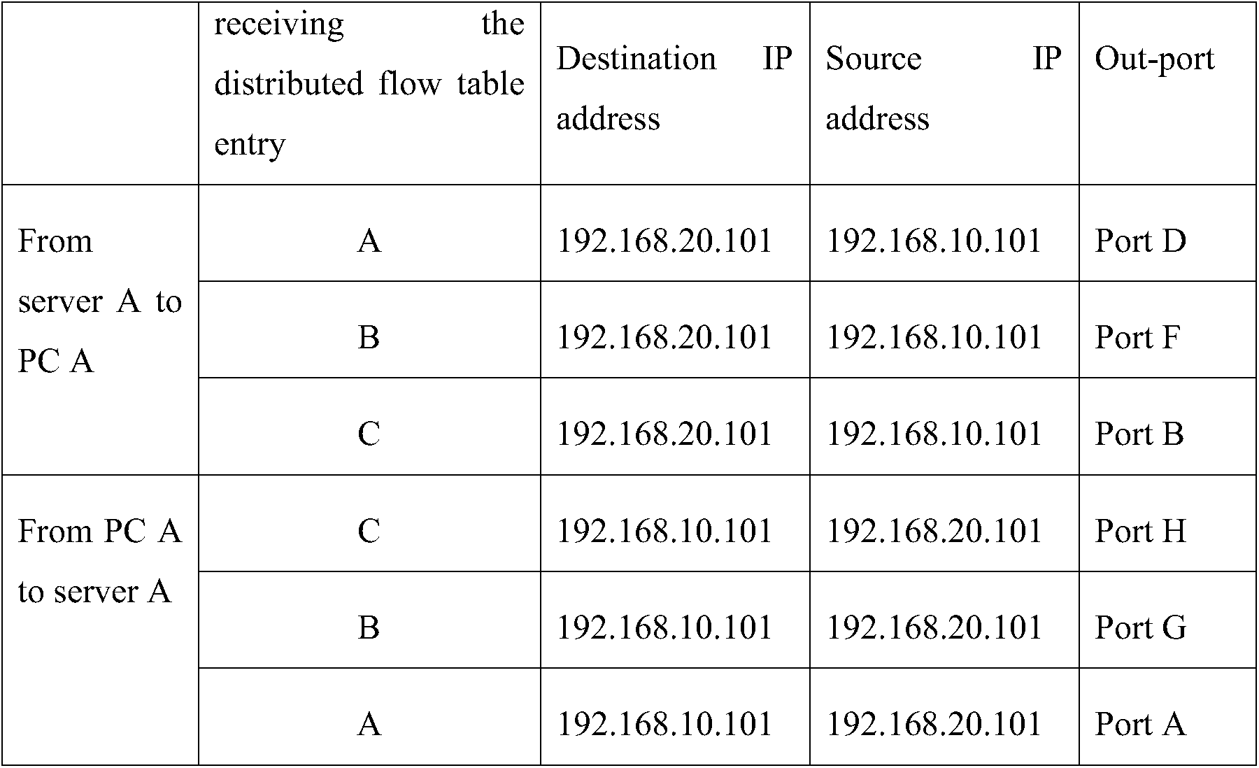
Table 3 Flow table entries distributed to forwarding devices A, B and C by the controller
Further, with respect to forwarding devices A to D, the link bandwidth between each pair of connected forwarding devices is updated as shown in Table 4.

Table 4 Updated link bandwidth between each pair of connected forwarding devices
In the examples of the present disclosure, the SDN may be an OpenFlow network.
FIG. 9 is a schematic diagram illustrating a structure of an apparatus for reserving bandwidth in SDN according to an example of the present disclosure. As shown in FIG. 9, the apparatus includes a first module 901, a second module 902, and a third module 903.
The first module 901 acquires a SDN topology structure.
The second module 902 acquires a link bandwidth between each pair of connected forwarding devices in the SDN according to the SDN topology structure acquired by the first module 901.
The third module 903 reserves a bandwidth for a designated user device according to the link bandwidth between each pair of connected forwarding devices acquired by the second module 902.
The first module 901 may acquire a SDN topology structure, which may include the following procedures: the first module 901 acquires the SDN topology structure between a forwarding device and a user device according to a packet-in packet received from the forwarding device which encapsulates a packet sent by the user device; and acquires the SDN topology structure between a forwarding device and another forwarding device according to a packet-in packet received from the forwarding device which encapsulates a pre-determined packet sent by the another forwarding device.
The second module 902 may acquire a link bandwidth between each pair of connected forwarding devices in the SDN according to the SDN topology structure acquired by the first module 901, which may include the following procedures: the second module 902 acquires a bandwidth of each port reported by a forwarding device in the SDN; acquires two connection ports of a link between two connected forwarding devices according to the SDN topology structure acquired by the first module 901; and when bandwidths reported by the two connected forwarding devices respectively for the two connection ports are identical, determines the bandwidths as the link bandwidth between the two connected forwarding devices; or, when bandwidths reported by the two connected forwarding devices respectively for the two connection ports are not identical, determines a lower bandwidth as the link bandwidth between the two connected forwarding devices.
The third module 903 may reserve a bandwidth for a designated user device according to the link bandwidth between each pair of connected forwarding devices acquired by the second module 902, which may include the following procedures: the third module 903 determines the pre-determined bandwidth reserved for a first user device towards a second user device; calculates all paths from the first user device to the second user device according to the SDN topology structure acquired by the second module 902; selects a path from the calculated paths, reserves the predetermined bandwidth for the first user device on the selected path; and according to the selected path, distributes to forwarding devices in the selected path a flow table entry from the first user device to the second user device and a flow table entry from the second user device to the first user device.
The third module 903 may select the path from the calculated paths, which may include the following procedures: the third module 903 ranks the calculated paths in an ascending order according to a cost of each calculated path, and selects a path with a bandwidth larger than the predetermined bandwidth by starting from a path with a lowest cost or a second lowest cost.
The apparatus for reserving bandwidth in SDN may further include a fourth module 904.
When receiving a packet-in packet from a forwarding device which carries a DHCP request packet, the fourth module 904 parses the DHCP request packet from the packet-in packet, determines a user device which sends the DHCP request packet according to a source MAC address of the DHCP request packet, allocates an IP address for the user device, carries the IP address in a DHCP response packet, encapsulates the DHCP response packet in an packet-out packet, and sends the packet-out packet to the user device via a forwarding device; wherein each of the first user device and the second user device in the flow table entry is identified by an IP address.
when receiving a packet-in packet from a forwarding device which carries an IP address reporting packet, the fourth module 904 parses the IP address reporting packet from the packet-in packet, and obtains an IP address of a local user device of the forwarding device from the IP address reporting packet; wherein each of the first user device and the second user device in the flow table entry is identified by an IP address.
FIG. 10 is a schematic diagram illustrating a structure of a network device according to an example of the present disclosure. The network device may include: a processor 1010, a non-transitory machine-readable storage medium 1020, and a bus 1030. The processor 1010 and the machine-readable storage medium 1020 are connected by the bus 1030.
The processor 1010 is configured to execute modules of machine-readable instructions stored in the machine-readable storage medium 1020.
The machine-readable storage medium 1020 is configured to store the machine-readable instruction modules executed by the processor 1010. The modules executed by the processor 1010 may include: the first module 901, the second module 902, the third module 903 and the fourth module 904. When executed by the processor 1010, the above-described functions of the first module 901, the second module 902, the third module 903 and the fourth module 904 may be achieved.
In this case, the instructions read from the storage medium can implement the functions of any of the aforementioned examples, and therefore, the instructions and the machine-readable storage medium storing the instructions constitute a part of the present disclosure.
A non-transitory “machine-readable storage medium” may be any electronic, magnetic, optical, or other physical storage apparatus to contain or store information such as executable instructions, data, and the like. For example, any machine-readable storage medium described herein may be any of Random Access Memory (RAM) , volatile memory, non-volatile memory, flash memory, a storage drive (e.g., a hard drive) , a solid state drive, any type of storage disc (e.g., a compact disc, a DVD, etc. ) , and the like, or a combination thereof. Further, any machine-readable storage medium described herein may be non-transitory.
According to the above-described examples of the present disclosure, it can be seen that by reserving a bandwidth for a designated user device according to the acquired link bandwidth between each pair of connected forwarding devices, the user experience in the SDN is enhanced, and a problem of frequent connection of user devices when there is a lot of flow available in the SDN is solved.
The foregoing is preferred examples of the present disclosure, which is not intended to limit the present disclosure. Any modifications, equivalents, and improvements made within the spirit and principle of the present disclosure should be covered by the scope of the present disclosure.
Claims (15)
- A method for reserving bandwidth in a Software Defined Network (SDN) , comprising:acquiring, by a controller, a SDN topology structure;acquiring, by the controller, a link bandwidth between each pair of connected forwarding devices in the SDN according to the acquired SDN topology structure; andreserving, by the controller, a bandwidth for a designated user device according to the acquired link bandwidth between each pair of connected forwarding devices.
- The method according to claim 1, wherein acquiring the SDN topology structure comprises:acquiring the SDN topology structure between a forwarding device and a user device according to a packet-in packet received from the forwarding device which encapsulates a packet sent by the user device;acquiring the SDN topology structure between a forwarding device and another forwarding device according to a packet-in packet received from the forwarding device which encapsulates a pre-determined packet sent by the another forwarding device.
- The method according to claim 1, wherein acquiring the link bandwidth between each pair of connected forwarding devices in the SDN according to the acquired SDN topology structure comprises:acquiring a bandwidth of each port reported by a forwarding device in the SDN;acquiring two connection ports of a link between two connected forwarding devices according to the acquired SDN topology structure;when bandwidths reported by the two connected forwarding devices respectively for the two connection ports are identical, determining the bandwidths as the link bandwidth between the two connected forwarding devices; or, when bandwidths reported by the two connected forwarding devices respectively for the two connection ports are not identical, determining a lower bandwidth as the link bandwidth between the two connected forwarding devices.
- The method according to claim 1, wherein reserving the bandwidth for the designated user device according to the acquired link bandwidth between each pair of connected forwarding devices comprises:determining the pre-determined bandwidth reserved for a first user device towards a second user device;calculating all paths from the first user device to the second user device according to the acquired SDN topology structure;selecting a path from the calculated paths, and reserving the predetermined bandwidth for the first user device on the selected path; andaccording to the selected path, distributing to forwarding devices in the selected path a flow table entry from the first user device to the second user device and a flow table entry from the second user device to the first user device.
- The method according to claim 4, wherein selecting the path from the calculated paths comprises:ranking the calculated paths in an ascending order according to a cost of each calculated path, and selecting a path with a bandwidth larger than the predetermined bandwidth by starting from a path with a lowest cost or a second lowest cost.
- The method according to claim 4, further comprising:in response to receiving a packet-in packet from a forwarding device which carries a Dynamic Host Configuration Protocol (DHCP) request packet, parsing the DHCP request packet from the packet-in packet, determining a user device which sends the DHCP request packet according to a source Media Access Control (MAC) address of the DHCP request packet, allocating an Internet Protocol (IP) address for the user device, carrying the IP address in a DHCP response packet, encapsulating the DHCP response packet in an packet-out packet, and sending the packet-out packet to the user device via a forwarding device;wherein each of the first user device and the second user device in the flow table entry is identified by an IP address.
- The method according to claim 4, further comprising:in response to receiving a packet-in packet from a forwarding device which carries an Internet Protocol (IP) address reporting packet, parsing the IP address reporting packet from the packet-in packet, and obtaining an IP address of a local user device of the forwarding device from the IP address reporting packet;wherein each of the first user device and the second user device in the flow table entry is identified by an IP address.
- A network device for reserving bandwidth in a Software Defined Network (SDN) , comprising: a processor and a non-transitory storage medium storing machine-readable instructions those are executable by the processor to:acquire a SDN topology structure;acquire a link bandwidth between each pair of connected forwarding devices in the SDN according to the acquired SDN topology structure; andreserve a bandwidth for a designated user device according to the acquired link bandwidth between each pair of connected forwarding devices.
- The network device according to claim 8, wherein the machine-readable instructions are executable by the processor to:acquire the SDN topology structure between a forwarding device and a user device according to a packet-in packet received from the forwarding device which encapsulates a packet sent by the user device;acquire the SDN topology structure between a forwarding device and another forwarding device according to a packet-in packet received from the forwarding device which encapsulates a pre-determined packet sent by the another forwarding device.
- The network device according to claim 8, wherein the machine-readable instructions are executable by the processor to:acquire a bandwidth of each port reported by a forwarding device in the SDN;acquire two connection ports of a link between two connected forwarding devices according to the acquired SDN topology structure;when bandwidths reported by the two connected forwarding devices respectively for the two connection ports are identical, determine the bandwidths as the link bandwidth between the two connected forwarding devices; or, when bandwidths reported by the two connected forwarding devices respectively for the two connection ports are not identical, determine a lower bandwidth as the link bandwidth between the two connected forwarding devices.
- The network device according to claim 8, wherein the machine-readable instructions are executable by the processor to:determine the pre-determined bandwidth reserved for a first user device towards a second user device;calculate all paths from the first user device to the second user device according to the acquired SDN topology structure;select a path from the calculated paths, and reserve the predetermined bandwidth for the first user device on the selected path; andaccording to the selected path, distribute to forwarding devices in the selected path a flow table entry from the first user device to the second user device and a flow table entry from the second user device to the first user device.
- The network device according to claim 11, wherein the machine-readable instructions are executable by the processor to:rank the calculated paths in an ascending order according to a cost of each calculated path, and select a path with a bandwidth larger than the predetermined bandwidth by starting from a path with a lowest cost or a second lowest cost.
- The network device according to claim 11, wherein the machine-readable instructions are executable by the processor to:when receiving a packet-in packet from a forwarding device which carries a Dynamic Host Configuration Protocol (DHCP) request packet, parse the DHCP request packet from the packet-in packet, determine a user device which sends the DHCP request packet according to a source Media Access Control (MAC) address of the DHCP request packet, allocate an Internet Protocol (IP) address for the user device, carry the IP address in a DHCP response packet, encapsulate the DHCP response packet in an packet-out packet, and send the packet-out packet to the user device via a forwarding device;wherein each of the first user device and the second user device in the flow table entry is identified by an IP address.
- The network device according to claim 11, wherein the machine-readable instructions are executable by the processor to:when receiving a packet-in packet from a forwarding device which carries an Internet Protocol (IP) address reporting packet, parse the IP address reporting packet from the packet-in packet, and obtain an IP address of a local user device of the forwarding device from the IP address reporting packet;wherein each of the first user device and the second user device in the flow table entry is identified by an IP address.
- A non-transitory storage medium, storing machine-readable instructions executable by a processor for reserving bandwidth in a Software Defined Network (SDN) , the instructions comprising instructions to:acquire a SDN topology structure;acquire a link bandwidth between each pair of connected forwarding devices in the SDN according to the acquired SDN topology structure; andreserve a bandwidth for a designated user device according to the acquired link bandwidth between each pair of connected forwarding devices.
Applications Claiming Priority (2)
| Application Number | Priority Date | Filing Date | Title |
|---|---|---|---|
| CN201410134517.XA CN104980368A (en) | 2014-04-03 | 2014-04-03 | Bandwidth guarantee method and apparatus in software defined network (SDN) |
| CN201410134517.X | 2014-04-03 |
Publications (1)
| Publication Number | Publication Date |
|---|---|
| WO2015149676A1 true WO2015149676A1 (en) | 2015-10-08 |
Family
ID=54239396
Family Applications (1)
| Application Number | Title | Priority Date | Filing Date |
|---|---|---|---|
| PCT/CN2015/075452 Ceased WO2015149676A1 (en) | 2014-04-03 | 2015-03-31 | Reserving bandwidth in software defined network |
Country Status (2)
| Country | Link |
|---|---|
| CN (1) | CN104980368A (en) |
| WO (1) | WO2015149676A1 (en) |
Cited By (5)
| Publication number | Priority date | Publication date | Assignee | Title |
|---|---|---|---|---|
| CN105491178A (en) * | 2015-11-23 | 2016-04-13 | 北京邮电大学 | Method for acquiring IP addresses of network adapters of host based on software-defined network |
| CN105763463A (en) * | 2016-01-27 | 2016-07-13 | 杭州华三通信技术有限公司 | Method and device for transmitting link detection message |
| US20170141995A1 (en) * | 2015-11-13 | 2017-05-18 | Nanning Fugui Precision Industrial Co., Ltd. | Data delivery method based on software defined networking and software defined networking controller using the method |
| CN107786351A (en) * | 2016-08-24 | 2018-03-09 | 中国电信股份有限公司 | Service bandwidth self-adapting regulation method, system and SDN controllers |
| CN111935034A (en) * | 2020-08-05 | 2020-11-13 | 上海映驰科技有限公司 | Stream reservation method, system and computer device for time sensitive network |
Families Citing this family (3)
| Publication number | Priority date | Publication date | Assignee | Title |
|---|---|---|---|---|
| CN107277190B (en) * | 2017-07-14 | 2019-09-20 | 中国联合网络通信集团有限公司 | A method for automatic on-line of SDN equipment, SDN equipment and controller |
| CN107645556B (en) * | 2017-09-26 | 2018-12-07 | 中国联合网络通信有限公司广东省分公司 | It is a kind of to realize that SDN turns the isolated broadband access of control and keepalive method and device |
| CN107682191B (en) * | 2017-09-30 | 2021-10-29 | 中国电力科学研究院 | A method and system for centralized management and control of power dispatching network information |
Citations (4)
| Publication number | Priority date | Publication date | Assignee | Title |
|---|---|---|---|---|
| CN1859298A (en) * | 2005-10-26 | 2006-11-08 | 华为技术有限公司 | Path selecting method |
| CN101155131A (en) * | 2006-09-29 | 2008-04-02 | 中国电信股份有限公司 | Method for establishing label switched path of minimized path preemption cost |
| EP1986370A1 (en) * | 2006-02-10 | 2008-10-29 | Huawei Technologies Co., Ltd. | Control system, data message transmission method and network device in the ethernet |
| CN102904809A (en) * | 2011-07-26 | 2013-01-30 | 华为技术有限公司 | Method, device and system for bandwidth resource management of LSP (label switched path) |
-
2014
- 2014-04-03 CN CN201410134517.XA patent/CN104980368A/en active Pending
-
2015
- 2015-03-31 WO PCT/CN2015/075452 patent/WO2015149676A1/en not_active Ceased
Patent Citations (4)
| Publication number | Priority date | Publication date | Assignee | Title |
|---|---|---|---|---|
| CN1859298A (en) * | 2005-10-26 | 2006-11-08 | 华为技术有限公司 | Path selecting method |
| EP1986370A1 (en) * | 2006-02-10 | 2008-10-29 | Huawei Technologies Co., Ltd. | Control system, data message transmission method and network device in the ethernet |
| CN101155131A (en) * | 2006-09-29 | 2008-04-02 | 中国电信股份有限公司 | Method for establishing label switched path of minimized path preemption cost |
| CN102904809A (en) * | 2011-07-26 | 2013-01-30 | 华为技术有限公司 | Method, device and system for bandwidth resource management of LSP (label switched path) |
Cited By (9)
| Publication number | Priority date | Publication date | Assignee | Title |
|---|---|---|---|---|
| US20170141995A1 (en) * | 2015-11-13 | 2017-05-18 | Nanning Fugui Precision Industrial Co., Ltd. | Data delivery method based on software defined networking and software defined networking controller using the method |
| US10003519B2 (en) * | 2015-11-13 | 2018-06-19 | Nanning Fugui Precision Industrial Co., Ltd. | Data delivery method based on software defined networking and software defined networking controller using the method |
| CN105491178A (en) * | 2015-11-23 | 2016-04-13 | 北京邮电大学 | Method for acquiring IP addresses of network adapters of host based on software-defined network |
| CN105763463A (en) * | 2016-01-27 | 2016-07-13 | 杭州华三通信技术有限公司 | Method and device for transmitting link detection message |
| CN105763463B (en) * | 2016-01-27 | 2020-01-03 | 新华三技术有限公司 | Method and device for transmitting link detection message |
| CN107786351A (en) * | 2016-08-24 | 2018-03-09 | 中国电信股份有限公司 | Service bandwidth self-adapting regulation method, system and SDN controllers |
| CN107786351B (en) * | 2016-08-24 | 2021-02-12 | 中国电信股份有限公司 | Service bandwidth self-adaptive adjusting method and system and SDN controller |
| CN111935034A (en) * | 2020-08-05 | 2020-11-13 | 上海映驰科技有限公司 | Stream reservation method, system and computer device for time sensitive network |
| CN111935034B (en) * | 2020-08-05 | 2023-04-18 | 上海映驰科技有限公司 | Stream reservation method, system and computer device for time sensitive network |
Also Published As
| Publication number | Publication date |
|---|---|
| CN104980368A (en) | 2015-10-14 |
Similar Documents
| Publication | Publication Date | Title |
|---|---|---|
| US20170078210A1 (en) | Controlling Packet Transmission In Software Defined Network | |
| US8750121B2 (en) | Addressing the large flow problem for equal cost multi-path in the datacenter | |
| US9325609B2 (en) | Segmented source routing in a network | |
| US11855891B2 (en) | Packet processing method and apparatus | |
| US20150163152A1 (en) | Performance-based routing in software-defined network (sdn) | |
| KR20210024649A (en) | Network slice control method and device, and computer-readable storage medium | |
| US10742697B2 (en) | Packet forwarding apparatus for handling multicast packet | |
| US9917766B2 (en) | Loop-free hybrid network | |
| CN104753713A (en) | SDN (Self-Defending Network) service deployment method and SDN controller | |
| US9736066B2 (en) | Method, apparatus and system for establishing optical bypass | |
| JP6589060B2 (en) | Software-defined network entry generation and packet forwarding | |
| CN111263373A (en) | Data processing method, controller and forwarding device | |
| EP3253012B1 (en) | Method and apparatus for obtaining port path | |
| CN104980368A (en) | Bandwidth guarantee method and apparatus in software defined network (SDN) | |
| US20190260812A1 (en) | Allocating capacity of a network connection to data streams based on type | |
| CN109672621B (en) | Method and equipment for selecting transmission path for VPN service | |
| US8855015B2 (en) | Techniques for generic pruning in a trill network | |
| US20150263954A1 (en) | Communication system, virtual machine server, virtual network management apparatus, network control method, and program | |
| US20190044857A1 (en) | Deadline driven packet prioritization for ip networks | |
| KR101541168B1 (en) | Route control method for flow of controller in software defined network | |
| CN106992963B (en) | Information processing method and gateway | |
| CN105991447A (en) | Segmented routing identification SID processing method and apparatus thereof | |
| HK1241578B (en) | Allocating capacity of a network connection to data steams based on type |
Legal Events
| Date | Code | Title | Description |
|---|---|---|---|
| 121 | Ep: the epo has been informed by wipo that ep was designated in this application |
Ref document number: 15774235 Country of ref document: EP Kind code of ref document: A1 |
|
| NENP | Non-entry into the national phase | ||
| 122 | Ep: pct application non-entry in european phase |
Ref document number: 15774235 Country of ref document: EP Kind code of ref document: A1 |