WO2015137498A1 - Ink-jet recording method - Google Patents
Ink-jet recording method Download PDFInfo
- Publication number
- WO2015137498A1 WO2015137498A1 PCT/JP2015/057547 JP2015057547W WO2015137498A1 WO 2015137498 A1 WO2015137498 A1 WO 2015137498A1 JP 2015057547 W JP2015057547 W JP 2015057547W WO 2015137498 A1 WO2015137498 A1 WO 2015137498A1
- Authority
- WO
- WIPO (PCT)
- Prior art keywords
- ink
- inkjet
- hollow fiber
- actinic ray
- molecular weight
- Prior art date
Links
Images


Classifications
-
- B—PERFORMING OPERATIONS; TRANSPORTING
- B41—PRINTING; LINING MACHINES; TYPEWRITERS; STAMPS
- B41J—TYPEWRITERS; SELECTIVE PRINTING MECHANISMS, i.e. MECHANISMS PRINTING OTHERWISE THAN FROM A FORME; CORRECTION OF TYPOGRAPHICAL ERRORS
- B41J2/00—Typewriters or selective printing mechanisms characterised by the printing or marking process for which they are designed
- B41J2/005—Typewriters or selective printing mechanisms characterised by the printing or marking process for which they are designed characterised by bringing liquid or particles selectively into contact with a printing material
- B41J2/01—Ink jet
- B41J2/17—Ink jet characterised by ink handling
- B41J2/19—Ink jet characterised by ink handling for removing air bubbles
-
- B—PERFORMING OPERATIONS; TRANSPORTING
- B41—PRINTING; LINING MACHINES; TYPEWRITERS; STAMPS
- B41J—TYPEWRITERS; SELECTIVE PRINTING MECHANISMS, i.e. MECHANISMS PRINTING OTHERWISE THAN FROM A FORME; CORRECTION OF TYPOGRAPHICAL ERRORS
- B41J2/00—Typewriters or selective printing mechanisms characterised by the printing or marking process for which they are designed
- B41J2/005—Typewriters or selective printing mechanisms characterised by the printing or marking process for which they are designed characterised by bringing liquid or particles selectively into contact with a printing material
- B41J2/01—Ink jet
- B41J2/17—Ink jet characterised by ink handling
- B41J2/175—Ink supply systems ; Circuit parts therefor
-
- C—CHEMISTRY; METALLURGY
- C09—DYES; PAINTS; POLISHES; NATURAL RESINS; ADHESIVES; COMPOSITIONS NOT OTHERWISE PROVIDED FOR; APPLICATIONS OF MATERIALS NOT OTHERWISE PROVIDED FOR
- C09D—COATING COMPOSITIONS, e.g. PAINTS, VARNISHES OR LACQUERS; FILLING PASTES; CHEMICAL PAINT OR INK REMOVERS; INKS; CORRECTING FLUIDS; WOODSTAINS; PASTES OR SOLIDS FOR COLOURING OR PRINTING; USE OF MATERIALS THEREFOR
- C09D11/00—Inks
- C09D11/02—Printing inks
- C09D11/10—Printing inks based on artificial resins
- C09D11/101—Inks specially adapted for printing processes involving curing by wave energy or particle radiation, e.g. with UV-curing following the printing
-
- C—CHEMISTRY; METALLURGY
- C09—DYES; PAINTS; POLISHES; NATURAL RESINS; ADHESIVES; COMPOSITIONS NOT OTHERWISE PROVIDED FOR; APPLICATIONS OF MATERIALS NOT OTHERWISE PROVIDED FOR
- C09D—COATING COMPOSITIONS, e.g. PAINTS, VARNISHES OR LACQUERS; FILLING PASTES; CHEMICAL PAINT OR INK REMOVERS; INKS; CORRECTING FLUIDS; WOODSTAINS; PASTES OR SOLIDS FOR COLOURING OR PRINTING; USE OF MATERIALS THEREFOR
- C09D11/00—Inks
- C09D11/02—Printing inks
- C09D11/12—Printing inks based on waxes or bitumen
-
- C—CHEMISTRY; METALLURGY
- C09—DYES; PAINTS; POLISHES; NATURAL RESINS; ADHESIVES; COMPOSITIONS NOT OTHERWISE PROVIDED FOR; APPLICATIONS OF MATERIALS NOT OTHERWISE PROVIDED FOR
- C09D—COATING COMPOSITIONS, e.g. PAINTS, VARNISHES OR LACQUERS; FILLING PASTES; CHEMICAL PAINT OR INK REMOVERS; INKS; CORRECTING FLUIDS; WOODSTAINS; PASTES OR SOLIDS FOR COLOURING OR PRINTING; USE OF MATERIALS THEREFOR
- C09D11/00—Inks
- C09D11/30—Inkjet printing inks
- C09D11/32—Inkjet printing inks characterised by colouring agents
- C09D11/322—Pigment inks
-
- B—PERFORMING OPERATIONS; TRANSPORTING
- B41—PRINTING; LINING MACHINES; TYPEWRITERS; STAMPS
- B41M—PRINTING, DUPLICATING, MARKING, OR COPYING PROCESSES; COLOUR PRINTING
- B41M7/00—After-treatment of prints, e.g. heating, irradiating, setting of the ink, protection of the printed stock
- B41M7/0081—After-treatment of prints, e.g. heating, irradiating, setting of the ink, protection of the printed stock using electromagnetic radiation or waves, e.g. ultraviolet radiation, electron beams
Definitions
- the present invention relates to an inkjet recording method.
- the ink jet recording method is used for forming various images because an image can be formed easily and inexpensively.
- One of the inks used in the ink jet recording system is actinic ray curable ink jet ink.
- actinic ray curable ink jet ink most of the ink components are cured by irradiation with actinic rays such as ultraviolet rays. Therefore, compared to the solvent-based ink composition, the ejected ink is easier to fix and the image is less likely to bleed. Therefore, there is an advantage that images can be formed on various recording media.
- Image formation by the ink jet recording method is usually performed by ejecting ink from a recording head of an ink jet recording apparatus.
- ink is ejected from the recording head, if the ink contains bubbles, ejection failure may occur.
- the actinic ray curable ink jet ink described above particularly the actinic ray curable ink jet ink containing wax, has a higher viscosity than solvent-based inks and the like, and bubbles mixed during ink production and storage are difficult to degas. For this reason, defective ejection from the ink jet recording apparatus tends to occur (for example, Patent Document 1).
- a method for removing bubbles contained in the ink for example, a method in which the ink before filling the cartridge is circulated through the hollow fiber degassing module (for example, Patent Document 2); A method (for example, Patent Document 3) of deaerating ink immediately before ejection using a deaeration filter has been proposed. Furthermore, a method of degassing ink by spraying ink in a reduced pressure space provided in the ink jet recording apparatus has been proposed (for example, Patent Document 4). In addition, a method (for example, Patent Document 5) in which deaeration is performed by causing ink to flow for a long time in a reduced pressure space provided in an ink jet recording apparatus has also been proposed.
- the actinic ray curable ink jet ink in addition to the above-described problem (discharge failure), the dissolved oxygen in the ink is liable to be inhibited by oxygen during ink curing, and the curability of the ink is low. There is also a problem. Therefore, it is conceivable to degas the ink by the various methods described above.
- the actinic ray curable inkjet ink may have a relatively high viscosity as described above. Air bubbles contained in the curable inkjet ink could not be removed sufficiently.
- the present invention has been made in view of the above circumstances, and provides an ink jet recording method capable of sufficiently removing bubbles contained in an actinic radiation curable ink jet ink and improving ejection stability and curability. With the goal.
- An ink jet recording method comprising: a step of landing on a medium; and a step of irradiating an ink droplet landed on the recording medium with an actinic ray to cure the ink droplet.
- the photopolymerizable compound has a molecular weight of 400 to 1500, and the inkjet ink contains 30 to 70% by mass of the photopolymerizable compound with respect to the total amount of the inkjet ink.
- the inkjet recording method as described.
- an ink jet recording method that can sufficiently remove bubbles contained in an actinic ray curable ink jet ink and can improve ejection stability and curability.
- the inventors of the present invention can sufficiently remove bubbles contained in the ink when the actinic ray curable inkjet ink containing a relatively high molecular weight component is degassed while heating, and further cure unevenness of the image output product. I found that there are few.
- a general actinic ray curable ink-jet ink is composed of a polymerizable compound having a relatively low molecular weight because of restrictions on viscosity at the time of ejection. Therefore, when the ink is degassed while reducing the pressure, the photopolymerizable compound volatilizes, and the composition of the ink ejected from the ink jet recording apparatus changes.
- the actinic radiation curable inkjet ink used in the inkjet recording method of the present invention contains a photopolymerizable compound having a relatively high molecular weight (molecular weight of 250 to 1500). For this reason, even if the degassing is performed while heating, the composition of the ink hardly changes, and the curability of the output image hardly changes. Further, in the method of the present invention, the viscosity of the ink at the time of deaeration is lowered by heating, so that the ink can be efficiently deaerated. Therefore, according to the method of the present invention, the ink can be stably ejected from the recording head, and the curability of the obtained image output product is uniform.
- the method can cope with high-speed image output. Furthermore, in the ink jet recording method of the present invention, since the photopolymerizable compound is less likely to volatilize from the actinic ray curable ink jet ink, an effect that odor is hardly generated during the deaeration process can be obtained.
- Actinic ray curable inkjet ink contains a photopolymerizable compound, a coloring material, and a photopolymerization initiator, and further contains other components as necessary. May be.
- the photopolymerizable compound contained in the actinic ray curable inkjet is a compound that crosslinks or polymerizes upon irradiation with actinic rays.
- the actinic rays are, for example, electron beams, ultraviolet rays, ⁇ rays, ⁇ rays, and X-rays, and are preferably ultraviolet rays.
- the actinic ray curable inkjet ink contains a photopolymerizable compound having a molecular weight of 250 to 1500.
- the molecular weight of the photopolymerizable compound is preferably 400 to 1500, and more preferably 600 to 1500.
- the photopolymerizable compound is unlikely to volatilize in the degassing step described later.
- the amount of the photopolymerizable compound is 1500 or less, the viscosity of the actinic radiation curable inkjet ink is not excessively increased, and the ejection stability from the inkjet recording apparatus is improved.
- the photopolymerizable compound having a molecular weight of 250 to 1500 is preferably contained in an amount of 30 to 70% by mass, more preferably 40 to 70% by mass, and even more preferably 50% by mass with respect to the total amount of the actinic ray curable inkjet ink. -70% by mass.
- amount of the photopolymerizable compound is 30% by mass or more, a component that volatilizes when the ink is deaerated decreases, and unevenness or the like hardly occurs in the curability of the image output product.
- the amount of the photopolymerizable compound is 70% by mass or less, the viscosity of the ink at the time of ejection becomes low, and high ejection stability is obtained.
- the photopolymerizable compound having a molecular weight of 250 to 1500 may be a radical polymerizable compound.
- the radical polymerizable compound can be a compound having an ethylenically unsaturated bond capable of radical polymerization, and may be any of a monomer, an oligomer, a polymer, or a mixture thereof.
- the actinic ray curable ink-jet ink may contain only one kind of radically polymerizable compound having a molecular weight of 250 to 1500, or two or more kinds thereof.
- Examples of the compound having an ethylenically unsaturated bond capable of radical polymerization include an unsaturated carboxylic acid or a salt thereof; an unsaturated carboxylic acid ester compound; an unsaturated carboxylic acid urethane compound; an unsaturated carboxylic acid amide compound or an anhydride thereof; Unsaturated polyester; unsaturated polyether; unsaturated polyamide; unsaturated urethane and the like.
- the radical polymerizable compound is preferably an unsaturated carboxylic acid ester compound, and in particular, a (meth) acrylate compound (monomer or oligomer) or a modified product thereof, or an oligomer obtained by adding a polymerizable functional group to a (meth) acrylate compound.
- (meth) acrylate refers to either or both of “acrylate” and “methacrylate”
- (meth) acryl” refers to either or both of “acryl” and “methacryl”.
- Examples of “(meth) acrylate monomers” having a molecular weight of 250-1500 include stearyl (meth) acrylate, lauryl methacrylate, isomyristyl (meth) acrylate, isostearyl (meth) acrylate, 2-ethylhexyl-diglycol (meth) Acrylate, 2- (meth) acryloyloxyethyl hexahydrophthalic acid, methoxypolyethylene glycol (meth) acrylate, 2- (meth) acryloyloxyethyl phthalic acid, 2- (meth) acryloyloxyethyl-2-hydroxyethyl -Monofunctional monomers such as phthalic acid; Triethylene glycol di (meth) acrylate, tetraethylene glycol di (meth) acrylate, polyethylene glycol di (meth) acrylate, tripropylene glycol di (meth) acrylate, polypropylene glycol
- Examples of the “(meth) acrylate oligomer” having a molecular weight of 250 to 1500 include the oligomer of the above (meth) acrylate monomer, the oligomer of the (meth) acrylate monomer having a molecular weight of less than 250, which will be described later.
- examples of “modified products of (meth) acrylate compounds” having a molecular weight of 250 to 1500 include ethylene oxide modified (meth) acrylates such as ethylene oxide modified trimethylolpropane tri (meth) acrylate and ethylene oxide modified pentaerythritol tetraacrylate. ) Acrylate compounds; caprolactone-modified (meth) acrylate compounds such as caprolactone-modified trimethylolpropane tri (meth) acrylate; and caprolactam-modified (meth) acrylate compounds such as caprolactam-modified dipentaerythritol hexa (meth) acrylate.
- the “modified product of the (meth) acrylate compound” is highly photosensitive and has an ethylene oxide modification (from the viewpoint of easily forming a card house structure described later when wax is contained in the actinic radiation curable inkjet ink.
- a meth) acrylate compound is preferred.
- the ethylene oxide-modified (meth) acrylate compound is easily dissolved in other ink components at high temperatures and has little curing shrinkage, so that curling of the printed matter hardly occurs.
- ethylene oxide-modified (meth) acrylate compound examples include 4EO-modified hexanediol diacrylate CD561 (molecular weight 358), 3EO-modified trimethylolpropane triacrylate SR454 (molecular weight 429), 6EO-modified trimethylolpropane tris manufactured by Sartomer.
- oligomers obtained by adding a further polymerizable functional group to a (meth) acrylate compound having a molecular weight of 250 to 1500 include epoxy (meth) acrylate oligomers, aliphatic urethane (meth) acrylate oligomers, and aromatic urethanes.
- (Meth) acrylate oligomers, polyester (meth) acrylate oligomers, linear (meth) acrylic oligomers and the like are included.
- the photopolymerizable compound having a molecular weight of 250 to 1500 may include not only a radical polymerizable compound but also a cationic polymerizable compound.
- the cationically polymerizable compound can be an epoxy compound, a vinyl ether compound, an oxetane compound, or the like. Only one kind of the cationic polymerizable compound may be contained in the actinic ray curable inkjet ink, or two or more kinds thereof may be contained.
- the “epoxy compound” that can be a cationically polymerizable compound is an aromatic epoxide, an alicyclic epoxide, an aliphatic epoxide, or the like. From the viewpoint of enhancing the curability of the ink, the aromatic epoxide and the alicyclic epoxide are used. Is preferred.
- the aromatic epoxide can be a di- or polyglycidyl ether obtained by reacting a polyhydric phenol or an alkylene oxide adduct thereof with epichlorohydrin.
- examples of the polyhydric phenol to be reacted or its alkylene oxide adduct include bisphenol A or its alkylene oxide adduct.
- the alkylene oxide in the alkylene oxide adduct can be ethylene oxide, propylene oxide, and the like.
- the alicyclic epoxide may be a cycloalkane oxide-containing compound obtained by epoxidizing a cycloalkane-containing compound with an oxidizing agent such as hydrogen peroxide or peracid.
- the cycloalkane in the cycloalkane oxide-containing compound can be cyclohexene or cyclopentene.
- the aliphatic epoxide can be a di- or polyglycidyl ether obtained by reacting an aliphatic polyhydric alcohol or an alkylene oxide adduct thereof with epichlorohydrin.
- the aliphatic polyhydric alcohol include ethylene glycol, propylene glycol, alkylene glycol such as 1,6-hexanediol, and the like.
- the alkylene oxide in the alkylene oxide adduct can be ethylene oxide, propylene oxide, and the like.
- the “vinyl ether compound” which can be a cationically polymerizable compound can be a monovinyl ether compound such as octadecyl vinyl ether;
- an “oxetane compound” that can be a cationically polymerizable compound is a compound having an oxetane ring, and examples thereof include JP-A Nos. 2001-220526, 2001-310937, and JP-A-2005-255821.
- the oxetane compounds described in the publication are included. Among them, the compound represented by the general formula (1) described in paragraph No. 0089 of JP-A No. 2005-255821, the compound represented by the general formula (2) described in paragraph No.
- paragraph Examples include a compound represented by general formula (7) of number 0107, a compound represented by general formula (8) of paragraph number 0109, a compound represented by general formula (9) of paragraph number 0116, and the like.
- the general formulas (1), (2), (7) to (9) described in JP-A-2005-255821 are shown below.
- the actinic ray curable inkjet ink may contain a part of the photopolymerizable compound having a molecular weight of less than 250.
- the amount of the photopolymerizable compound having a molecular weight of less than 250 is preferably less than 30% by mass, more preferably less than 20% by mass based on the total mass of the actinic ray curable inkjet ink.
- the amount of the photopolymerizable compound having a molecular weight of less than 250 is less than 30% by mass, the amount of components that volatilize when the ink is deaerated decreases. As a result, unevenness or the like hardly occurs in the curability of the image output product.
- the photopolymerizable compound having a molecular weight of less than 250 may be a radical polymerizable compound or a cationic polymerizable compound.
- the radical polymerizable compound having a molecular weight of less than 250 is also unsaturated carboxylic acid or a salt thereof; unsaturated carboxylic acid ester compound; unsaturated carboxylic acid urethane compound; unsaturated carboxylic acid amide compound or anhydride thereof; unsaturated polyester; It may be polyether; unsaturated polyamide; unsaturated urethane; acrylonitrile; styrene or the like.
- Examples of the unsaturated carboxylic acid having a molecular weight of less than 250 include (meth) acrylic acid, itaconic acid, crotonic acid, isocrotonic acid, maleic acid and the like.
- the photopolymerizable compound having a molecular weight of less than 250 is particularly preferably an unsaturated carboxylic acid ester compound, and may be, for example, a monomer of a (meth) acrylate compound or an oligomer thereof.
- Examples of (meth) acrylate monomers having a molecular weight of less than 250 include isoamyl (meth) acrylate, lauryl acrylate, octyl (meth) acrylate, decyl (meth) acrylate, 2-hydroxybutyl (meth) acrylate, butoxyethyl (meth) Acrylate, ethoxydiethylene glycol (meth) acrylate, methoxydiethylene glycol (meth) acrylate, methoxypropylene glycol (meth) acrylate, phenoxyethyl (meth) acrylate, tetrahydrofurfuryl (meth) acrylate, isobornyl (meth) acrylate, 2-hydroxyethyl ( (Meth) acrylate, 2-hydroxypropyl (meth) acrylate, 2-hydroxy-3-phenoxypropyl (meth) acrylate, 2- Meth) acryloyloxyethyl succinic acid
- the photopolymerizable compound having a molecular weight of less than 250 may be a cationic polymerizable compound as described above.
- cationically polymerizable compounds having a molecular weight of less than 250 include ethyl vinyl ether, n-butyl vinyl ether, isobutyl vinyl ether, cyclohexyl vinyl ether, hydroxybutyl vinyl ether, 2-ethylhexyl vinyl ether, cyclohexanedimethanol monovinyl ether, n-propyl vinyl ether, isopropyl vinyl ether.
- Monovinyl ether compounds such as isopropenyl ether-o-propylene carbonate, dodecyl vinyl ether, diethylene glycol monovinyl ether; Diethylene glycol divinyl ether, diethylene glycol divinyl ether, triethylene glycol divinyl ether, propylene glycol divinyl ether, dipropylene glycol divinyl ether, butanediol divinyl ether, hexanediol divinyl ether, cyclohexane dimethanol divinyl ether, trimethylolpropane trivinyl ether, etc. Or a trivinyl ether compound etc. are contained. Of these vinyl ether compounds, di- or trivinyl ether compounds are preferred in view of curability and adhesion.
- the actinic ray curable inkjet ink may contain a photopolymerizable compound having a molecular weight of more than 1500.
- the amount of the photopolymerizable compound having a molecular weight of more than 1500 is preferably less than 30% by mass, more preferably less than 15% by mass based on the total mass of the actinic ray curable inkjet ink.
- the amount of the photopolymerizable compound having a molecular weight of more than 1500 is less than 30% by mass, the viscosity of the ink does not increase excessively, and the ejection stability tends to increase.
- the photopolymerizable compound having a molecular weight exceeding 1500 may be a radical polymerizable compound or a cationic polymerizable compound.
- the radically polymerizable compound having a molecular weight exceeding 1500 is not particularly limited, and may be, for example, a polymer or modified product of the above-described photopolymerizable compound having a molecular weight of 1500 or less.
- the color material contained in the actinic ray curable ink-jet ink can be a dye or a pigment, but a pigment is preferable because an image having good weather resistance can be easily obtained.
- the pigment is not particularly limited, and may be, for example, an organic pigment or an inorganic pigment having the following numbers described in the color index.
- red or magenta pigments examples include Pigment Red 3, 5, 19, 22, 31, 38, 43, 48: 1, 48: 2, 48: 3, 48: 4, 48: 5, 49: 1, 53. : 1, 57: 1, 57: 2, 58: 4, 63: 1, 81, 81: 1, 81: 2, 81: 3, 81: 4, 88, 104, 108, 112, 122, 123, 144 146, 149, 166, 168, 169, 170, 177, 178, 179, 184, 185, 208, 216, 226, 257, Pigment Violet 3, 19, 23, 29, 30, 37, 50, 88, Pigment Orange 13, 16, 20, 36, etc. are included.
- Examples of blue or cyan pigments include Pigment Blue 1, 15, 15: 1, 15: 2, 15: 3, 15: 4, 15: 6, 16, 17-1, 22, 27, 28, 29, 36. , 60 and the like.
- Examples of green pigments include Pigment Green 7, 26, 36, and 50.
- Examples of yellow pigments include Pigment Yellow 1, 3, 12, 13, 14, 17, 34, 35, 37, 55, 74, 81, 83, 93, 94, 95, 97, 108, 109, 110, 137. 138, 139, 153, 154, 155, 157, 166, 167, 168, 180, 185, 193 and the like.
- Examples of the black pigment include Pigment Black 7, 28, 26 and the like.
- the volume average particle diameter of the pigment is preferably 0.08 to 0.5 ⁇ m, and the maximum particle diameter of the pigment is preferably 0.3 to 10 ⁇ m, more preferably 0.3 to 3 ⁇ m.
- the pigment content is preferably from 0.1 to 20% by mass, more preferably from 0.4 to 10% by mass, based on the total amount of the actinic ray curable inkjet ink. If the pigment content is too small, the color of the resulting image tends to be low. On the other hand, when the content of the pigment is too large, the viscosity of the ink is increased and the ejection properties of the ink droplets are liable to be lowered.
- the pigment is dispersed by, for example, a ball mill, a sand mill, an attritor, a roll mill, an agitator, a Henschel mixer, a colloid mill, an ultrasonic homogenizer, a pearl mill, a wet jet mill, a paint shaker, and the like, and the average particle diameter of the pigment particles is within the above range. It is preferable to be dispersed as follows. The dispersibility of the pigment is adjusted by the selection of the pigment, the pigment dispersant, and the dispersion medium, the dispersion conditions, the filtration conditions, and the like.
- the actinic ray curable inkjet ink may further contain a pigment dispersant in order to enhance the dispersibility of the pigment.
- pigment dispersants include hydroxyl group-containing carboxylic acid esters, salts of long chain polyaminoamides and high molecular weight acid esters, salts of high molecular weight polycarboxylic acids, salts of long chain polyaminoamides and polar acid esters, high molecular weight unsaturated acids.
- Ester, polymer copolymer, modified polyurethane, modified polyacrylate, polyether ester type anionic activator, naphthalenesulfonic acid formalin condensate salt, aromatic sulfonic acid formalin condensate salt, polyoxyethylene alkyl phosphate ester, polyoxy Ethylene nonylphenyl ether, stearylamine acetate and the like are included.
- Examples of commercially available pigment dispersants include Avecia's Solsperse series and Ajinomoto Fine Techno's PB series (for example, Azisper PB824).
- the amount of the pigment dispersant contained in the actinic ray curable inkjet ink is preferably 1 to 50% by mass with respect to the pigment.
- Photopolymerization initiators contained in the actinic ray curable ink jet ink include an intramolecular bond cleavage type and an intramolecular hydrogen abstraction type.
- Examples of intramolecular bond cleavage type photopolymerization initiators include diethoxyacetophenone, 2-hydroxy-2-methyl-1-phenylpropan-1-one, benzyldimethyl ketal, 1- (4-isopropylphenyl) -2 -Hydroxy-2-methylpropan-1-one, 4- (2-hydroxyethoxy) phenyl- (2-hydroxy-2-propyl) ketone, 1-hydroxycyclohexyl-phenylketone, 2-methyl-2-morpholino (4 Acetophenones such as -thiomethylphenyl) propan-1-one and 2-benzyl-2-dimethylamino-1- (4-morpholinophenyl) -butanone; benzoins such as benzoin, benzoin
- intramolecular hydrogen abstraction type photopolymerization initiators include benzophenone, methyl 4-phenylbenzophenone, o-benzoylbenzoate, 4,4'-dichlorobenzophenone, hydroxybenzophenone, 4-benzoyl-4'-methyl-diphenyl Benzophenones such as sulfide, acrylated benzophenone, 3,3 ′, 4,4′-tetra (t-butylperoxycarbonyl) benzophenone, 3,3′-dimethyl-4-methoxybenzophenone; 2-isopropylthioxanthone, 2,4 -Thioxanthone series such as dimethylthioxanthone, 2,4-diethylthioxanthone, 2,4-dichlorothioxanthone; Aminobenzophenone series such as Michler's ketone, 4,4'-diethylaminobenzophenone; 10-Butyl-2-chloroaclide
- the photopolymerization initiator is an acyl phosphine oxide or an acyl phosphonate
- the light sensitivity of the actinic ray curable inkjet ink becomes good.
- bis (2,4,6-trimethylbenzoyl) -phenylphosphine oxide, bis (2,6-dimethoxybenzoyl) -2,4,4-trimethyl-pentylphosphine oxide and the like are preferable.
- the amount of the photopolymerization initiator contained in the actinic radiation curable inkjet ink is appropriately selected depending on the light irradiated during ink curing, the type of the photopolymerizable compound, and the like, but is 0 with respect to the total mass of the actinic radiation curable inkjet ink. It is preferably 1% by mass to 10% by mass, and more preferably 2% by mass to 8% by mass.
- the photopolymerization initiator may contain a photoacid generator.
- photoacid generators include chemically amplified photoresists and compounds used for photocationic polymerization (Organic Materials Research Group, “Organic Materials for Imaging”, Bunshin Publishing (1993), 187. See page 192).
- the actinic ray curable ink-jet ink may further contain a photopolymerization initiator auxiliary agent or a polymerization inhibitor, if necessary.
- the photopolymerization initiator assistant may be a tertiary amine compound, preferably an aromatic tertiary amine compound.
- aromatic tertiary amine compounds include N, N-dimethylaniline, N, N-diethylaniline, N, N-dimethyl-p-toluidine, N, N-dimethylamino-p-benzoic acid ethyl ester, N, N-dimethylamino-p-benzoic acid isoamyl ethyl ester, N, N-dihydroxyethylaniline, triethylamine, N, N-dimethylhexylamine and the like are included.
- N, N-dimethylamino-p-benzoic acid ethyl ester and N, N-dimethylamino-p-benzoic acid isoamyl ethyl ester are preferred.
- One kind of these compounds may be contained in the ink, or two or more kinds thereof may be contained.
- polymerization inhibitors include (alkyl) phenol, hydroquinone, catechol, resorcin, p-methoxyphenol, t-butylcatechol, t-butylhydroquinone, pyrogallol, 1,1-picrylhydrazyl, phenothiazine, p-benzoquinone , Nitrosobenzene, 2,5-di-t-butyl-p-benzoquinone, dithiobenzoyl disulfide, picric acid, cuperone, aluminum N-nitrosophenylhydroxylamine, tri-p-nitrophenylmethyl, N- (3-oxyanilino- 1,3-Dimethylbutylidene) aniline oxide, dibutylcresol, cyclohexanone oxime cresol, guaiacol, o-isopropylphenol, butyraloxime, methyl ethyl ketoxime, cyclohexanone oxime
- the actinic ray curable inkjet ink may further contain a wax. Since the wax usually has a hydrophobic group, the wax tends to interact with the highly hydrophobic pigment surface. Therefore, when the wax is contained, the liquid component of the actinic radiation curable inkjet ink is easily wetted on the pigment surface, and the bubble nuclei on the pigment surface are easily removed. When such actinic ray curable ink-jet ink containing wax is deaerated under heating and reduced pressure, bubbles in the ink are more easily removed.
- the ink droplet contains wax
- the ink droplet after landing on the recording medium has a high viscosity and does not spread excessively so that oxygen does not dissolve on the surface of the ink droplet. Accordingly, the curability of the image output product is further increased.
- waxes examples include An aliphatic ketone compound; Aliphatic ester compounds; Petroleum waxes such as paraffin wax, microcrystalline wax, petrolactam; Plant waxes such as candelilla wax, carnauba wax, rice wax, wood wax, jojoba oil, jojoba solid wax, and jojoba ester; Animal waxes such as beeswax, lanolin and whale wax; Mineral waxes such as montan wax and hydrogenated wax; Hydrogenated castor oil or hydrogenated castor oil derivative; Modified waxes such as montan wax derivatives, paraffin wax derivatives, microcrystalline wax derivatives or polyethylene wax derivatives; Higher fatty acids such as behenic acid, arachidic acid, stearic acid, palmitic acid, myristic acid, lauric acid, oleic acid, and erucic acid; Higher alcohols such as stearyl alcohol and behenyl alcohol; Hydroxystearic acid such as 12-hydroxystearic acid; 12-hydroxystearic acid derivative
- Nomucoat series, etc. Amide compounds such as N-lauroyl-L-glutamic acid dibutylamide and N- (2-ethylhexanoyl) -L-glutamic acid dibutylamide (available from Ajinomoto Fine Techno); Dibenzylidene sorbitols such as 1,3: 2,4-bis-O-benzylidene-D-glucitol (available from Gelol D Shin Nippon Rika); And low molecular oil waxes described in JP-A-2005-126507, JP-A-2005-255821 and JP-A-2010-11117.
- Amide compounds such as N-lauroyl-L-glutamic acid dibutylamide and N- (2-ethylhexanoyl) -L-glutamic acid dibutylamide (available from Ajinomoto Fine Techno); Dibenzylidene sorbitols such as 1,3: 2,4-bis-O-benzyliden
- the wax preferably has a function of reversibly changing the sol-gel phase of the ink depending on the temperature.
- a wax is desired to be at least 1) soluble in the photopolymerizable compound at a temperature higher than the gelling temperature, and 2) crystallized in the ink at a temperature below the gelling temperature.
- a plurality of the plate-like crystals gather to form a three-dimensional structure including a space inside, and the photopolymerizable compound may be held inside the structure.
- Such a structure is generally called a “card house structure”.
- the card house structure is formed in the ink droplet, the liquid photopolymerizable compound is held inside the structure.
- ink droplets are easily pinned, and coalescence of the droplets is suppressed.
- the photopolymerizable compound dissolved in the ink and the wax are compatible. If the photopolymerizable compound dissolved in the ink and the wax are phase-separated, the card house structure may be difficult to form.
- the compatibility between the photopolymerizable compound and the wax is good in the sol-like ink (at a high temperature). Furthermore, in order to stably suppress coalescence of droplets even during high-speed printing, it is desired that the wax crystallizes quickly after the ink droplets have landed on the recording medium to form a strong card house structure. .
- the wax is preferably a compound having an alkyl group having 12 or more carbon atoms.
- the alkyl group may be any one of a linear alkyl group, a branched alkyl group, and a cyclic alkyl group, and is preferably a linear alkyl group or a branched alkyl group, and the above-mentioned “card house structure” From the viewpoint that it is easy to form, a linear alkyl group is more preferable.
- wax having a linear alkyl group having 12 or more carbon atoms examples include aliphatic ketone compounds, aliphatic ester compounds, higher fatty acids, higher alcohols, fatty acid amides and the like having a linear alkyl group having 12 or more carbon atoms. Is included.
- the wax is preferably a compound represented by the following general formula (G1) or (G2).
- the hydrocarbon groups represented by R 1 and R 2 in the general formula (G1) are each independently preferably an aliphatic hydrocarbon group including a straight chain portion having 12 to 25 carbon atoms.
- the number of carbon atoms in the straight chain portion contained in the aliphatic hydrocarbon group represented by R 1 and R 2 is less than 12, sufficient crystallinity may not be obtained.
- the above-mentioned card house structure there is a possibility that a sufficient space for encapsulating the photopolymerizable compound cannot be formed.
- the number of carbon atoms in the straight chain portion contained in the aliphatic hydrocarbon group exceeds 25, the melting point becomes too high. For this reason, unless the ink ejection temperature is increased, the ink may not be dissolved.
- Examples of the aliphatic ketone compound represented by the general formula (G1) include dilignoceryl ketone (C24-C24), dibehenyl ketone (C22-C22, melting point 88 ° C.), distearyl ketone (C18-C18, 84 ° C.), dieicosyl ketone (C20-C20), dipalmityl ketone (C16-C16, melting point 80 ° C.), dimyristyl ketone (C14-C14), dilauryl ketone (C12-C12, melting point 68 ° C.) , Lauryl myristyl ketone (C12-C14), lauryl palmityl ketone (C12-C16), myristyl palmityl ketone (C14-C16), myristyl stearyl ketone (C14-C18), myristyl behenyl ketone (C14-C22), palmityl Stearyl
- Examples of commercially available compounds represented by the general formula (G1) include 18-Pentriacontanon (manufactured by Alfa Aeser), Hentriacontan-16-on (manufactured by Alfa Aeser), Kao wax T1 (manufactured by Kao Corporation), and the like. included.
- the aliphatic ketone compound contained in the actinic ray curable inkjet ink may be only one kind or a mixture of two or more kinds.
- the hydrocarbon group represented by R 3 and R 4 in the general formula (G2) is not particularly limited, but is preferably an aliphatic hydrocarbon group including a linear portion having 12 to 26 carbon atoms. .
- the number of carbon atoms in the straight chain portion contained in the aliphatic hydrocarbon group represented by R 3 and R 4 is 12 or more and 26 or less, as in the compound represented by the general formula (G1), a good crystal It is easy to form a card house structure. Also, the melting point of the wax does not increase excessively.
- Examples of the aliphatic ester compound represented by the formula (G2) include behenyl behenate (C21-C22, melting point 70 ° C.), icosyl icosanoate (C19-C20), stearyl stearate (C17-C18, melting point 60 ° C.).
- Examples of commercially available products of the aliphatic ester compound represented by the formula (G2) include Unistar M-2222SL (manufactured by NOF Corporation), EXCEPARL SS (manufactured by Kao Corporation, melting point 60 ° C.), EMALEXCC-18 (Japan) Emulsion Co., Ltd.), Amreps PC (manufactured by Higher Alcohol Industry Co., Ltd.), Exepal MY-M (Kao Co., Ltd.), Spam Acechi (Nissho Co., Ltd.), EMALEX® CC-10 (Nihon Emulsion Co., Ltd.) included. Since these commercial products are often a mixture of two or more types, they may be separated and purified as necessary.
- the aliphatic ester compound contained in the actinic ray curable inkjet ink may be only one type or a mixture of two or more types.
- the amount of the wax contained in the actinic radiation curable inkjet ink is preferably 1.0 to 10.0% by mass, more preferably 1.0 to 7.0% by mass with respect to the total mass of the ink. .
- the amount of the wax is less than 1.0% by mass, the liquid component of the actinic radiation curable inkjet ink is not sufficiently wetted on the pigment surface, and the cell nuclei on the pigment surface may not be sufficiently removed. Further, there is a possibility that the ink droplet cannot be sufficiently gelled (or sol-gel phase transition).
- the amount of the wax exceeds 10% by mass, the wax cannot be sufficiently dissolved in the ink, and there is a possibility that the ejection property of the ink droplets is lowered.
- the actinic ray curable inkjet ink may further contain other components as necessary.
- Other components may be various additives, other resins, and the like.
- the additive include a surfactant, a leveling additive, a matting agent, an ultraviolet absorber, an infrared absorber, an antibacterial agent, and a basic compound for enhancing the storage stability of the ink.
- basic compounds include basic alkali metal compounds, basic alkaline earth metal compounds, basic organic compounds such as amines, and the like.
- other resins include resins for adjusting the physical properties of the cured film, such as polyester resins, polyurethane resins, vinyl resins, acrylic resins, rubber resins, and waxes. It is.
- the actinic ray curable ink-jet ink preferably has a viscosity of the ink at a high temperature or less in order to improve the discharge property of ink droplets and the deaeration property in the deaeration process described later.
- the viscosity of the actinic ray curable inkjet ink at 80 ° C. is preferably 3 to 20 mPa ⁇ s.
- the actinic ray curable inkjet ink preferably has a viscosity of the ink at a certain temperature or higher after landing in order to suppress coalescence of adjacent dots.
- the viscosity of the ink at 25 ° C. is preferably 1000 mPa ⁇ s or more.
- the actinic ray curable inkjet ink when the actinic ray curable inkjet ink contains a wax, the actinic ray curable inkjet ink undergoes a sol-gel phase transition reversibly depending on the temperature. Since the actinic ray curable inkjet ink is a liquid (sol) at a high temperature (for example, about 80 ° C.), it can be ejected from the recording head in a sol state. When actinic ray curable inkjet ink is ejected at a high temperature, ink droplets (dots) land on the recording medium and then naturally cool to gel. Thereby, the unification of adjacent dots is suppressed and the image quality is enhanced.
- a sol-gel phase transition reversibly depending on the temperature. Since the actinic ray curable inkjet ink is a liquid (sol) at a high temperature (for example, about 80 ° C.), it can be ejected from the recording head in a sol
- the gelling temperature of the actinic ray curable inkjet ink containing wax is preferably 30 ° C. or higher and lower than 100 ° C., more preferably 50 ° C. or higher and 65 ° C. or lower. If the gelation temperature of the ink is too high, gelation is likely to occur at the time of ejection, and the ejectability tends to be low. On the other hand, if the gelation temperature of the ink is too low, it does not gel immediately after landing on the recording medium.
- the gelation temperature is a temperature at which the fluidity is lowered due to gelation in the process of cooling the ink in the sol state.
- the viscosity at 80 ° C., the viscosity at 25 ° C., and the gelation temperature of the actinic radiation curable inkjet ink can be determined by measuring the temperature change of the dynamic viscoelasticity of the ink with a rheometer. Specifically, a temperature change curve of viscosity is obtained when the ink is heated to 100 ° C. and cooled to 20 ° C. under conditions of a shear rate of 11.7 (/ s) and a temperature decrease rate of 0.1 ° C./s. And the viscosity in 80 degreeC and the viscosity in 25 degreeC can be calculated
- the gelation temperature can be determined as the temperature at which the viscosity becomes 200 mPa ⁇ s in the temperature change curve of the viscosity.
- the rheometer can be a stress control type rheometer Physica MCR series manufactured by Anton Paar.
- the cone plate can have a diameter of 75 mm and a cone angle of 1.0 °.
- the inkjet recording method of the present invention comprises at least (1) a step of introducing an inkjet ink into a decompressed space in an inkjet recording apparatus and degassing the inkjet ink at an ink temperature of 50 ° C. or more and less than 120 ° C., (2) A step of ejecting the degassed actinic ray curable inkjet ink droplets from the recording head and landing on the recording medium; and (3) irradiating the ink droplets landing on the recording medium with actinic rays, Curing the ink droplets.
- the actinic ray curable inkjet ink may be the actinic ray curable inkjet ink described above.
- the actinic ray curable ink-jet ink in the ink-jet recording apparatus is degassed in a reduced pressure space in the ink-jet recording apparatus.
- the ink temperature at this time is 50 ° C. or higher and lower than 120 ° C.
- the entire space may be decompressed, or only a part of the space may be decompressed.
- a method for degassing ink for example, (i) a method of introducing ink into a decompression tank and removing bubbles from the ink, or (ii) a hollow fiber is disposed in the space, and the inside of the hollow fiber is decompressed. There is a method of removing bubbles from the ink.
- the method of this invention is not limited to these.
- One method of degassing ink is a method of introducing ink into a decompression tank.
- the temperature of the ink in the vacuum tank is 50 to 120 ° C., preferably 70 to 110 ° C., and more preferably 80 to 100 ° C.
- the method for controlling the ink temperature in the decompression tank to a desired range is not particularly limited, and the ink temperature may be adjusted by a heater or the like provided outside or inside the decompression tank.
- the temperature in the tank may be adjusted to a desired temperature by preheating the ink to be introduced into the decompression tank and introducing the ink.
- the ink temperature any one of the ink temperature before being introduced into the decompression tank and the ink temperature after being discharged from the decompression tank may satisfy the above temperature range, and it is preferable that both satisfy the above temperature range.
- the viscosity of the ink in the vacuum tank is preferably 1 to 1000 mPa ⁇ s, more preferably 1 to 100 mPa ⁇ s. When the viscosity of the ink is in the above range, bubbles are easily removed from the ink. The viscosity of the ink is measured with a rheometer as described above.
- the degree of vacuum in the decompression tank is appropriately selected according to the type of ink, the viscosity of the ink in the decompression tank, the ink flow rate, etc., but is preferably less than ⁇ 90 kPa, more preferably ⁇ 90. Is -98 kPa, more preferably -95 to -98 kPa. If the degree of vacuum in the decompression tank is less than ⁇ 90 kPa, bubbles in the ink are easily removed.
- the above-mentioned actinic ray curable ink-jet ink contains a photopolymerizable compound having a molecular weight of 250 to 1500, but the compound is difficult to volatilize even if the degree of vacuum is less than ⁇ 90 kPa. Therefore, the composition of the actinic ray curable ink jet ink hardly changes even after the deaeration step. On the other hand, if the degree of vacuum is higher than -90 kPa, the volatilization of the ink can be suppressed, but the performance of removing bubbles is lowered.
- a printing speed (relative speed between a printing apparatus and a recording medium at the time of printing) is 50 m / min or more
- the decompression space needs to be enlarged.
- the degree of vacuum is less than ⁇ 98 kPa, the volatilization amount of the ink increases, and the composition of the ink changes and the image quality is likely to deteriorate.
- the method for removing bubbles in the ink is not particularly limited, and may be a method of storing in the decompression tank for a predetermined time.
- deaeration is performed by moving bubbles in the ink toward the interface between ink and air. Is done. For this reason, if the surface area of the ink is increased, bubbles are likely to escape from the inside of the ink. Therefore, it is preferable to perform a process for increasing the surface area of the ink in the decompression tank.
- a method for increasing the surface area of ink there is a method of spraying ink into a vacuum tank.
- the ink is sprayed, the surface area of the ink becomes very large and bubbles in the ink are easily removed.
- the ink is sprayed by being pushed out while applying pressure to the ink from a nozzle 71 having a large number of holes.
- the nozzle 71 may have the same shape as a general fluid spray nozzle. Further, the pressurization to the ink is performed by a pump or the like.
- the droplet diameter of the ink pushed out from the nozzle 71 is not particularly limited, and can usually be about 30 to 500 ⁇ m.
- the ink droplet diameter is adjusted by the diameter of the hole of the nozzle 71 or the like.
- an ink flow path 73 is provided in a decompression tank 70 ′, and ink is allowed to flow through the flow path 73 little by little. sell.
- the ink moves along the flow path 73, the surface area of the ink increases.
- the ink moves in the decompression tank over time, bubbles are likely to escape from the ink to the air layer 81 side.
- the gas that has moved to the air layer 81 side is discharged to the outside of the decompression tank 70 ′ by the decompression pump 72.
- the flow path 73 may be a concave member, and its cross-sectional shape, depth, and width are also selected as appropriate.
- the depth of the flow path 73 is deep, the ink easily flows in a large amount at a time, and the ink is efficiently introduced into the decompression tank 70 '.
- the depth of the flow path 73 is shallow, the surface area of the ink is increased, and bubbles in the ink are easily removed.
- the width of the flow path 73 is wide, it becomes easy to introduce a large amount of ink at a time.
- the structure of the flow path 73 in the decompression tank 70 ′ is not particularly limited, and is moderately inclined with respect to the horizontal plane so that the ink reaches the bottom side of the decompression tank 70 ′ from the ink inlet 70F over time. As long as it is installed.
- the angle formed by the flow path 73 and the horizontal plane is appropriately selected according to the length of the flow path 73, the viscosity of the ink, and the like. Further, it is preferable that the flow path 73 is formed in a spiral shape or a zigzag shape in the decompression tank 70 ′ from the viewpoint of increasing the length of the flow path 73.
- the length of the flow path 73, the flow rate and flow rate of the ink flowing through the flow path 73 are not particularly limited, and are appropriately selected according to the viscosity of the ink.
- Other methods for increasing the ink surface area include a method of vibrating the ink stored in the decompression tank and a method of stirring the stored ink.
- the area of the interface between the ink and the air layer is increased by vibrating or stirring the ink stored in the decompression tank.
- vibration and agitation make it easier for air bubbles to be pushed out from the ink to the air layer side.
- the ink may be vibrated or agitated as long as it is a method in which air is not easily caught in the stored ink, and may be a known vibration method or agitating method. For example, it may be vibration by ultrasonic waves, stirring by a stirring blade, or the like.
- Method (ii) As another method of degassing the ink, there is a method of degassing with a hollow fiber built in the ink jet recording apparatus.
- the hollow fiber is a hollow (straw-shaped) yarn that allows gas to pass through but does not allow liquid to pass through.
- hollow fiber materials include polyolefin resins such as polypropylene and poly (4-methyl-1-pentene); silicone resins such as polydimethylsiloxane and copolymers thereof; fluorine resins such as PTFE and vinylidene fluoride Resin etc. are included. Of these, silicone resins and fluororesins are preferred from the viewpoint that the surface energy is easily increased by heating and the deaeration efficiency is easily increased.
- the properties of the side wall membrane of the hollow fiber may be a porous membrane, a non-porous membrane (homogeneous membrane having no pores), or a composite membrane combining these. Since the actinic ray curable inkjet ink tends to wet the surface of the hollow fiber, the hollow fiber is preferably a non-porous membrane.
- the hollow inner diameter of the hollow fiber can be about 50 to 500 ⁇ m.
- the film thickness of the hollow fiber can be about 10 to 150 ⁇ m.
- Hollow fiber can be used as an aggregate of hollow fibers.
- the aggregate of hollow fibers may be filled with one long hollow fiber; it may be a bundle of a plurality of hollow fibers or knitted.
- Examples of the bundle of a plurality of hollow fibers include a bundle-like body in which a plurality of hollow fibers are bundled so as to be arranged in parallel in the length direction.
- Examples of the one in which a plurality of hollow fibers are knitted include a sheet in which a plurality of hollow fibers are knitted together in a stitch shape, as shown in FIG.
- seat can be used as a winding body wound with respect to the axis
- a sheet in which a plurality of hollow fibers are knitted together has a fine hollow fiber, and since all the ink easily passes through the hollow fiber, it is easy to improve the deaeration efficiency; flexible This is preferable because a certain level of strength is easily obtained even from hollow fibers.
- the effective membrane area of the aggregate of hollow fibers can be about 0.1 to 5 m 2 , preferably about 0.3 to 2 m 2 , more preferably about 0.5 to 1 m 2 .
- the effective membrane area of the aggregate of hollow fibers can be defined as the surface area per hollow fiber (m 2 / line) ⁇ the number of hollow fibers (line).
- the ink is circulated outside (hollow outside) the hollow fiber placed in a space heated to a certain temperature, and the inside of the hollow fiber (hollow) Inner) depressurizing by depressurization (external reflux method), or decirculating by depressurizing the outer side of hollow fiber (outside hollow) and degassing inside hollow fiber (inside hollow) (internal reflux) Method).
- the external reflux method is preferable from the viewpoint of low ink pressure loss.
- the ink temperature in the space where the hollow fiber is arranged is 50 ° C. or higher and 120 ° C. or lower, preferably 60 ° C. or higher and 120 ° C. or lower, more preferably 80 ° C. or higher and 100 ° C. or lower. If the ink temperature when the ink is deaerated with the hollow fiber is too low, the surface energy of the hollow fiber is not sufficiently increased, so that the ink is not sufficiently wetted with the hollow fiber and the deaeration efficiency is not easily increased. On the other hand, if the deaeration temperature is too high, thermal radicals are generated in the ink or the pigment dispersibility becomes unstable, so that the storage stability of the ink tends to be lowered.
- the ink temperature may be any one of the ink temperature before being introduced into the space in which the hollow fiber is arranged and the ink temperature after being discharged from the space in which the hollow fiber is arranged to satisfy the above temperature range. It is preferable to satisfy.
- the ink temperature in the space where the hollow fiber is arranged can be adjusted by the heating means of the hollow fiber deaeration module described later.
- the heating means can be, for example, a jacket heater 29 provided on the outer periphery of the housing 27 of the hollow fiber deaeration module as shown in FIG.
- Ink introduced into the hollow fiber degassing module may be heated in advance, and the ink temperature in the hollow fiber degassing module may be adjusted to a desired temperature by introducing the ink.
- Ink droplets of the actinic ray curable inkjet ink deaerated as described above are ejected from the recording head.
- the actinic ray curable inkjet ink immediately before ejection is preferably heated to 60 to 100 ° C., preferably 60 to 80 ° C., from the viewpoint of enhancing the ejection properties of the ink droplets. If the temperature of the actinic radiation curable inkjet ink immediately before ejection is too low, the ink viscosity is too high, or if the ink contains wax, it will gel in the recording head or on the nozzle surface, causing ink droplet ejection properties Tends to decrease. On the other hand, if the temperature of the actinic ray curable inkjet ink immediately before ejection is too high, the ink component tends to deteriorate.
- the actinic ray curable inkjet ink is heated by a recording head of an inkjet recording apparatus, an ink flow path connected to the recording head, a deaeration module similar to the above-described deaeration process, and the like.
- the amount of droplets ejected from each nozzle of the recording head is preferably 0.5 to 10 pl, although it depends on the resolution of the image. In order to form a high-definition image, 0. It is more preferably 5 to 4 pl, and further preferably 0.5 to 2.5 pl.
- the actinic ray curable inkjet ink contains a wax, the ink droplet rapidly undergoes sol-gel transition. Therefore, even after the amount of liquid droplets, the ink after landing is difficult to unite, and a high-definition image is stably formed.
- the bubbles in the ink are sufficiently removed in the above-described steps, high ejection stability can be obtained.
- the ink droplets that have landed on the recording medium may be cooled.
- the actinic ray curable ink-jet ink contains a wax
- the ink droplets that have landed on the recording medium are rapidly gelled by the sol-gel phase transition. Therefore, when the ink droplets landed on the recording medium are cooled, the ink droplets are pinned without being wetted and spread. Further, since the ink viscosity increases due to gelation, it is difficult for oxygen to enter the ink droplets, and the curing of the photopolymerizable compound is not easily inhibited by oxygen.
- the recording medium may be paper or a resin film.
- the paper include coated paper for printing, art paper for printing, and the like.
- the resin film include a polyethylene terephthalate film, a polypropylene film, and a vinyl chloride film.
- the temperature of the recording medium when the ink droplets land is preferably set to a temperature that is 10 to 20 ° C. lower than the gelation temperature of the ink. If the temperature of the recording medium is too low, the ink droplets gel too quickly and are pinned. For this reason, ink droplets are not sufficiently leveled, and the glossiness of the image may be lowered. On the other hand, if the temperature of the recording medium is too high, the ink droplets are difficult to gel, and adjacent dots of the ink droplets may be mixed together. By appropriately adjusting the temperature of the recording medium, it is possible to achieve appropriate leveling and appropriate pinning so that adjacent dots of ink droplets do not mix with each other.
- the conveyance speed of the recording medium is preferably 100 to 1500 mm / s.
- the higher the conveyance speed the higher the image forming speed, which is preferable.
- the conveyance speed is too high, the image quality is deteriorated or the photocuring (described later) of the ink becomes insufficient.
- the actinic ray applied to the ink droplets attached to the recording medium is preferably ultraviolet light from an LED light source.
- LED light source Specific examples include Heraeus 395 nm, water-cooled LED, and the like.
- a metal halide lamp can be cited as a general ultraviolet light source.
- the LED light source is installed so that the peak illuminance on the image surface is 0.5 to 10 W / cm 2 with ultraviolet rays of 360 to 410 nm, and more preferably 1 to 5 W / cm 2 .
- the amount of light applied to the image is preferably less than 500 mJ / cm 2 , more preferably less than 350 mJ / cm 2 . This is to prevent the radiant heat from being applied to the ink droplets.
- Irradiation of the actinic ray to the ink droplets is performed within 10 seconds after the ink droplets adhere on the recording medium, preferably from 0.001 seconds to suppress the adjacent ink droplets from being coalesced. It is preferable to carry out within 5 seconds, more preferably within 0.01 second to 2 seconds. Irradiation with actinic rays is preferably performed after ink droplets are ejected from all the recording heads accommodated in the head carriage.
- the ink droplets may be cured by relatively moving the recording medium and the actinic ray light source at a speed of 50 m / min or more.
- the bubbles are sufficiently removed from the actinic ray curable inkjet ink as described above. That is, the amount of dissolved oxygen in the actinic ray curable inkjet ink is low. Therefore, there is little oxygen inhibition at the time of ink curing, and it is possible to cure at a high speed as described above.
- Inkjet recording apparatus The inkjet recording method of the present invention can be performed using an actinic ray curable inkjet recording apparatus.
- An ink jet recording apparatus of the present invention communicates between a recording head that discharges actinic ray curable ink jet ink, an ink tank that stores actinic ray curable ink jet ink supplied to the recording head, and the recording head and the ink tank.
- a deaeration module for deaerating the actinic radiation curable inkjet ink supplied from the ink tank, and an irradiation unit for irradiating the ink droplets ejected from the recording head with the actinic rays.
- the line recording method is preferable from the viewpoint of high-speed recording, although it may be selected according to the required image resolution and recording speed.
- FIG. 6 is a diagram illustrating an example of a configuration of a main part of a line recording type inkjet recording apparatus.
- Fig.6 (a) is a side view
- FIG.6 (b) is a top view.
- the inkjet recording apparatus 10 includes a head carriage 13 that houses a plurality of recording heads 11, an ink tank 17 that stores ink supplied through the ink flow path 15, an ink tank 17, and a head carriage 13.
- a deaeration module 19 that degass the ink supplied from the ink tank 17, and covers the entire width of the recording medium 20, and the head carriage 13 (represented by the recording medium transport direction (f) Direction)) an actinic ray irradiation unit 21 arranged on the downstream side and a temperature control unit 23 arranged on the lower surface of the recording medium 20.
- the head carriage 13 is fixedly arranged so as to cover the entire width of the recording medium 20 and accommodates a plurality of recording heads 11. Each head carriage 13 accommodates recording heads 11 of different colors.
- Ink is supplied to the recording head 11.
- the ink may be supplied directly or by an ink supply unit (not shown) from an ink cartridge (not shown) that is detachably attached to the inkjet recording apparatus 10.
- the number of recording heads 11 arranged in the conveyance direction of the recording medium 20 is set according to the nozzle density of the recording head 11 and the resolution of the print image. For example, when an image having a resolution of 1440 dpi is formed using the recording head 11 having a droplet amount of 2 pl and a nozzle density of 360 dpi, four recording heads with respect to the conveyance direction (direction represented by f) of the recording medium 20 are used. 11 may be shifted and arranged. Further, when an image having a resolution of 720 ⁇ 720 dpi is formed using the recording head 11 having a droplet amount of 6 pl and a nozzle density of 360 dpi, the two recording heads 11 may be arranged in a shifted manner. dpi represents the number of ink droplets (dots) per 2.54 cm.
- the ink tank 17 is connected to the head carriage 13 via an ink flow path 15 and a deaeration module 19.
- the ink flow path 15 is a path for supplying the ink in the ink tank 17 to the head carriage 13.
- the ink in the ink tank 17, the ink flow path 15, the head carriage 13, and the recording head 11 can be heated to a predetermined temperature.
- the deaeration module 19 is connected to the ink tank 17 and the head carriage 13 via the ink flow path 15. The ink supplied from the ink tank 17 is deaerated by the deaeration module 19 and then sent to the head carriage 13.
- the degassing module 19 As an example of the degassing module 19, a decompression tank, a decompression pump for degassing the decompression tank, means for increasing the surface area of the ink in the decompression tank, and heating means for heating the decompression tank (A vacuum degassing module).
- FIG. 1 is a schematic diagram showing an example of a vacuum degassing module.
- Arrow X indicates ink flow; arrow Y indicates bubble flow.
- the vacuum degassing module 79 includes a vacuum tank 70, a vacuum pump 72 for degassing the vacuum tank, a nozzle 71 for spraying ink into the vacuum tank, and a heating means for heating the vacuum tank. And a module (not shown).
- the decompression tank 70 includes a housing body 70A, a nozzle introduction port 70B for installing the nozzle 71, a suction port 70C for evacuating the inside of the housing body 70A, and an ink discharge port 70D for discharging the ink after deaeration. Including.
- the suction port 70 ⁇ / b> C is connected to the decompression pump 72.
- the ink discharge port 70 ⁇ / b> D is connected to the head carriage 13 via the ink flow path 15.
- the decompression tank 70 can also be provided with an air release pipe 70E for adjusting the pressure in the decompression tank 70.
- the nozzle 71 is connected to the ink tank 17 through the ink flow path 15.
- a pressurizing unit such as a pressurizing pump is installed between the ink flow path 15 and the nozzle 71 as necessary.
- the nozzle 71 is arranged so as to spray ink downward in the gravity direction, but the nozzle 71 is provided so as to spray ink in a desired direction such as upward in the gravity direction or horizontal direction (lateral direction). Also good.
- the decompression pump 72 is connected to the suction port 70 ⁇ / b> C of the decompression tank 70. By discharging the air inside the housing body 70A by the decompression pump 72, the inside of the housing body 70A is decompressed.
- the heating means can be provided, for example, so as to cover the outer peripheral surface of the housing main body 70A of the decompression tank 70, but is not limited thereto, and may be provided inside the housing main body 70A.
- the ink temperature in the housing main body 70A is adjusted to a predetermined temperature by the heating means. Note that the ink temperature inside the housing main body 70A may not rise to a desired range immediately after the ink jet device is operated. Therefore, the determination as to whether the ink temperature inside the housing main body 70A is within a desired range is made after a certain period of time has elapsed since the operation of the ink jet apparatus.
- the ink supplied from the ink tank 17 is supplied from the nozzle 71 into the housing main body 70A. Sprayed.
- the ink temperature in the housing main body 70A is adjusted by, for example, a heating means (not shown). Since the pressure inside the housing main body 70A is reduced, the bubbles contained in the sprayed ink immediately move to the air layer 81 side. Then, the gas is discharged to the outside of the decompression tank 70 through the suction port 70C (see arrow Y).
- the deaerated ink 80 is stored at the bottom of the housing main body 70A, and is sent from the ink discharge port 70D to the head carriage 13 side via the ink flow path 15.
- FIG. 2 is a schematic diagram showing another example of the vacuum degassing module.
- Arrow X indicates ink flow; arrow Y indicates bubble flow.
- the decompression deaeration module 79 ′ includes a decompression tank 70 ′, a decompression pump 72 for deaerating the decompression tank, a flow path 73 for allowing ink to flow little by little in the decompression tank 70 ′, and the decompression. And a module (not shown) including a heating means for heating the tank.
- the decompression tank 70 ′ includes a housing body 70A, an ink introduction port 70F for introducing ink, a suction port 70C for evacuating the inside of the housing body 70A, and an ink discharge port 70D for discharging the ink after deaeration. Including.
- the suction port 70 ⁇ / b> C is connected to the decompression pump 72.
- the ink introduction port 70 ⁇ / b> F is connected to the ink tank via the ink flow path 15.
- the ink discharge port 70 ⁇ / b> D is connected to the head carriage 13 via the ink flow path 15.
- the decompression tank 70 ′ may be provided with an atmosphere release pipe 70 ⁇ / b> E for adjusting the pressure in the decompression tank 70 ′.
- the flow path 73 is installed at an angle with respect to the horizontal direction so as to guide ink from the ink introduction port 70F (ink flow path 15) to the vicinity of the bottom of the housing main body 70A.
- the flow path 73 can be installed in a spiral shape or a zigzag shape on the wall surface or inside of the housing body 70A continuously or intermittently.
- the decompression pump 72 is connected to the suction port 70C of the decompression tank 70 '.
- the heating means can be provided, for example, so as to cover the outer peripheral surface of the housing main body 70A of the decompression tank 70 ', but is not limited thereto, and may be provided inside the housing main body 70A.
- the ink temperature in the housing main body 70A is adjusted to a predetermined temperature by the heating means. As described above, the ink temperature inside the housing main body 70A may not rise to a desired range immediately after the operation of the ink jet apparatus. Therefore, the determination as to whether the ink temperature inside the housing main body 70A is within a desired range is made after a certain period of time has elapsed since the operation of the ink jet apparatus.
- the vacuum degassing module 79 ′ thus configured, after the pressure inside the housing body 70 ⁇ / b> A is reduced to a desired degree of vacuum by the vacuum pump 72, ink is introduced from the ink inlet 70 ⁇ / b> F.
- the ink introduced into the housing main body 70A moves slowly along the flow path 73 to the bottom side of the housing main body 70A.
- the bubbles contained in the ink moving through the flow path 73 move to the air layer 81 side.
- the gas is discharged through the suction port 70C (see arrow Y).
- the deaerated ink 80 is stored at the bottom of the housing main body 70A, and is sent from the ink discharge port 70D to the head carriage 13 side via the ink flow path 15.
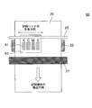
- the deaeration module 19 is a module (hollow fiber deaeration module) including an assembly of hollow fibers, a housing that houses the hollow fiber assembly, and a heating unit that heats the inside of the housing.
- the hollow fiber deaeration module may be an internal reflux type or an external reflux type.
- the hollow fiber can be the aforementioned hollow fiber.
- the heating means is not particularly limited, but may be a jacket heater provided on the outer periphery of the housing.
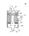
- FIG. 3 is a schematic view showing an example of an external reflux type hollow fiber deaeration module 89.
- Arrow X indicates ink flow; arrow Y indicates bubble flow.
- the hollow fiber deaeration module 89 includes a hollow fiber assembly 25, a housing 27 that houses the hollow fiber assembly 25, and a jacket heater 29 provided around the housing 27. including.
- the hollow fiber assembly 25 is preferably a sheet in which a plurality of hollow fibers 31 are arranged so as to be parallel to each other in the length direction (arranged so as to be parallel to each other as shown in FIG. 4).
- a sheet or the like obtained by knitting a plurality of hollow fibers 31 with warps 32 may be wound around a shaft parallel to the longitudinal direction of the hollow fibers 31.
- the hollow fiber 31 can be the hollow fiber described above.
- One end 25a of the hollow fiber assembly 25 (the end portion on the ink introduction port 33 side described later) is sealed between the hollow fibers 31 and the hole 31A of the hollow fiber with a sealing resin or the like. Ink cannot flow into the hollow fiber assembly 25.
- the other end 25b of the hollow fiber assembly 25 (the end on the suction port 35 side described later) is sealed between the hollow fibers 31 with a sealing resin or the like. Is not sealed and is open. Thereby, the inside of the hollow of the hollow fiber 31 (inside the hole 31A) can be depressurized.
- the housing 27 is in contact with the cylindrical housing main body 27A, the ink introduction port 33 for introducing ink into the housing main body 27A, the suction port 35 for evacuating the housing main body 27A, and the hollow fiber assembly 25. And an ink discharge port 37 through which the discharged ink is discharged.
- a central hole 39 surrounded by the hollow fiber assembly 25 and extending in parallel with the length direction of the hollow fiber 31 is formed in the central portion of the housing main body 27A. One end of the central hole 39 (end on the suction port 35 side) is sealed with a sealing resin or the like.
- the jacket heater 29 (heating means) can be provided so as to cover the outer peripheral surface of the housing main body 27A. Thereby, the ink temperature in the housing main body 27A can be adjusted to a predetermined temperature.
- the ink introduced into the housing main body 27A from the ink introduction port 33 circulates through the central hole 39; (Refer to arrow X); it flows through the outer surface of the hollow fiber 31 and is discharged from the ink discharge port 37.
- Ink is introduced into the housing body 27 ⁇ / b> A from the ink inlet 33 and flows through the central hole 39.
- the ink flowing through the central hole 39 flows from the side wall surface into the hollow fiber assembly 25 (arrow X); the ink flows through the outer surface of the hollow fiber 31.
- the ink in the housing main body 27A is heated to a certain temperature or higher by the jacket heater 29, so that the surface energy of the outer surface of the hollow fiber 31 increases, and the ink is hollow fiber. It becomes easy to get wet to the outer surface of 31. Thereby, the bubbles contained in the ink can be efficiently removed.
- the ink from which the bubbles are removed is discharged from the ink discharge port 37 of the hollow fiber deaeration module 89.
- the hollow fiber degassing module of the degassing module is not limited to the external reflux system, and may be an internal reflux system.
- FIG. 5 is a schematic view showing an example of an internal reflux type hollow fiber deaeration module.
- Arrow X indicates ink flow; arrow Y indicates bubble flow.
- the hollow fiber deaeration module 89 ′ includes a hollow fiber assembly 41, a housing 27 that accommodates the hollow fiber assembly 41, and a jacket heater 29 provided around the housing 27.
- the hollow fiber assembly 41 is formed by winding a sheet in which a plurality of hollow fibers 31 are arranged parallel to each other in the length direction, with an axis parallel to the length direction of the hollow fibers 31 as a center.
- One end 41a (end portion on the ink introduction port 33 side) of the hollow fiber assembly 41 is fixed by an introduction connection port 45 and a fixing member (shaded portion); the other end 41b (end portion on the ink discharge port 37 side) ) Is fixed by a discharge connection port 47 and a fixing member (shaded portion). This prevents ink from leaking out of the hollow fiber assembly 41.
- the introduction connection port 45 is connected to the ink introduction port 33; the discharge connection port 47 is connected to the ink discharge port 37.
- the housing 27 has a housing body 27A and a suction port 35 for evacuating the housing body 27A. Thereby, the inside of the housing main body 27A can be depressurized.
- the ink introduced into the hollow fiber deaeration module 89 ′ is introduced from the ink introduction port 33 into the hollow fiber assembly 41 through the introduction connection port 45; the hollow fiber 31 in the hollow (in the hole 31A). (See arrow X).
- the outside of the hollow fiber assembly 41 in the housing main body 27A is depressurized, the bubbles in the ink flowing through the hollow of the hollow fiber 31 permeate through the side wall membrane of the hollow fiber 31 to the outside. And discharged through the suction port 35 (see arrow Y).
- the ink in the housing main body 27 ⁇ / b> A is heated to a certain temperature by the jacket heater 29. Thereby, the surface energy of the hollow inner surface of the hollow fiber 31 is increased, and the ink is easily wetted in the hollow of the hollow fiber 31. Thereby, the bubbles contained in the ink can be efficiently removed.
- the ink from which bubbles are removed is discharged from the ink discharge port 37 through the discharge connection port 47.
- the actinic ray irradiating unit 21 covers the entire width of the recording medium 20 and is disposed on the downstream side of the head carriage 13 in the recording medium conveyance direction.
- the actinic ray irradiation unit 21 irradiates the droplets ejected by the recording head 11 and landed on the recording medium with light, thereby curing the droplets.
- the temperature control unit 23 is disposed on the lower surface of the recording medium 20, and maintains the recording medium 20 at a predetermined temperature.
- the temperature control unit 23 can be, for example, various heaters.
- the recording medium 20 is conveyed between the head carriage 13 and the temperature control unit 23 of the inkjet recording apparatus 10. On the other hand, the recording medium 20 is adjusted to a predetermined temperature by the temperature control unit 23.
- the ink in the ink tank 17 is introduced into the deaeration module 19 through the ink flow path 15.
- the deaeration module 19 is deaerated by various deaeration means and supplied to the recording head 11 in the head carriage 13.
- the total ink droplet thickness after curing is preferably 2 to 25 ⁇ m.
- the “total ink droplet thickness” is the maximum value of the ink droplet thickness drawn on the recording medium.
- FIG. 7 is a diagram illustrating an example of a configuration of a main part of the serial recording type inkjet recording apparatus 60.
- the inkjet recording apparatus 60 is provided with a width narrower than the entire width of the recording medium, instead of the head carriage 13 fixedly arranged so as to cover the entire width of the recording medium. 6, and a guide portion 65 for moving the head carriage 63 in the width direction of the recording medium 20.
- Members having the same or similar functions as those in FIG. 6 are denoted by the same reference numerals.
- the head carriage 63 moves from the recording head 61 accommodated in the head carriage 63 while moving in the width direction (direction indicated by w) of the recording medium 20 along the guide portion 65. A droplet is discharged. After the head carriage 63 has completely moved in the width direction of the recording medium 20 (for each pass), the recording medium 20 is sent in the transport direction (direction indicated by f), and the active light irradiation unit 21 irradiates the active light. Except for these operations, an image is recorded in substantially the same manner as the line recording type inkjet recording apparatus 10 described above.
- ⁇ Preparation of pigment dispersion> 8 parts by mass of efka7701 and 71 parts by mass of APG-200 were placed in a stainless beaker, and dissolved by heating and stirring for 1 hour while heating on a 65 ° C. hot plate. After cooling the mixed solution to room temperature, 20 parts by mass of yellow pigment Pigment Yellow 185 was added. The mixed solution was put in a glass bottle together with 200 g of zirconia beads having a diameter of 0.5 mm, sealed, and dispersed for 8 hours using a paint shaker. Thereafter, the zirconia beads were removed to prepare a yellow pigment dispersion.
- magenta pigment dispersion A magenta pigment dispersion was prepared in the same manner as the yellow pigment dispersion, except that the pigment was changed to magenta pigment Pigment Red 122.
- Example 1 ⁇ Preparation of yellow ink>
- a pigment 12.0 parts by mass of the aforementioned yellow pigment dispersion; 8.0 parts by mass of APG-200, 10.0 parts by mass of MK ester A-400, and MK ester A-600 as photopolymerizable compounds 10.0 parts by mass, Miramaer M3160 28.8 parts by mass, SR494 20.0 parts by mass; surfactant, KF352 (manufactured by Shin-Etsu Chemical Co., Ltd.) 0.05 part by mass; photopolymerization initiator DAROCURE TPO is 4.0 parts by mass, IRGACURE 819 is 2.0 parts by mass, SPEEDCURE ITX (manufactured by DKSH) is 2.0 parts by mass, and SPEEDCURE EDB (manufactured by DKSH) is 3.0 parts by mass; As an agent, 0.2 part by mass of UV10 (manufactured by BASF) was mixed and stirred at 80 ° C.
- Ther
- magenta ink was prepared in the same manner as the yellow ink except that the composition shown in Table 2 was changed.
- the ink supply system of the ink jet recording apparatus includes an ink tank, a supply pipe, a deaeration module, a sub ink tank immediately before the head, a pipe with a filter, and a piezo head (recording head) in this order. Then, the yellow ink and the magenta ink were respectively supplied to the ink tank of the ink jet apparatus. Then, the ink tank from the ink jet recording apparatus to the recording head was heated to 90 ° C. Moreover, the space in the deaeration module was decompressed to 97 kPa. The ink supply speed to the deaeration module was 200 cc / min.
- the recording head in the above-described inkjet recording apparatus is an inkjet head manufactured by Konica Minolta having 1776 nozzles, and the resolution is 600 dpi.
- the applied voltage was adjusted so that the amount of one droplet was 3.5 pl and the droplet velocity was 7 m / sec.
- Two heads were arranged in a staggered manner, and an image having a resolution of 1200 dpi ⁇ 1200 dpi was recorded.
- dpi represents the number of dots per 2.54 cm.
- the image was formed in an environment of 23 ° C. and 55% RH.
- the deaeration module has a structure in which an ink flow path 73 is spirally formed in a cylindrical decompression tank 70 'as shown in FIG.
- the flow path 73 was a concave member made of a fluororesin (recessed cross-sectional shape: semicircular shape).
- the total area of the upper surface of the flow path (the total area of the interface between the ink flowing through the flow path and the air layer) was 300 cm 2 .
- the ink temperature in the decompression tank 70 ' was adjusted by a jacket heater (not shown) installed on the outer periphery of the decompression tank 70' and heating means (not shown) provided in the vicinity of the ink inlet 70F of the decompression tank 70 '. .
- the ink temperature in the decompression tank 70 ′ (the temperature of the ink introduced into the decompression tank 70 ′) was 90 ° C.
- the degree of vacuum in the decompression tank 70 ′ was adjusted by the decompression pump 72 to ⁇ 90 kPa.
- the coated paper for printing (manufactured by OK KINFUJI rice basis weight 104.7 g / m 2 Oji Paper Co., Ltd.), a magenta ink printed in amount per of 9 g / m 2, to form a solid image of magenta.
- the coated paper for printing was irradiated with ultraviolet rays by an LED lamp (manufactured by Heraeus, 8 W / cm 2 , 395 nm, water cooled unit) disposed in the downstream portion of the ink jet recording apparatus to cure the ink.
- the distance between the LED lamp and the coated paper for printing during UV irradiation was 30 mm. Further, the relative speed between the LED lamp and the coated paper for printing at the time of ultraviolet irradiation was 60 m / min.
- a yellow ink and a magenta ink are each printed at a weight of 6 g / m 2 on a coated paper for printing (OK Kanito, US basis weight 104.7 g / m 2 manufactured by Oji Paper Co., Ltd.) and a polypropylene film (manufactured by Okamoto).
- a red solid image was formed.
- the coated paper for printing is irradiated with ultraviolet rays by an LED lamp (Heraeus, 8 W / cm 2 , 395 nm, water cooled unit) disposed in the downstream part of the inkjet recording apparatus, and landed on the coated paper for printing.
- the cured ink was cured.
- the distance between the LED lamp and the coated paper for printing during UV irradiation was 30 mm. Further, the relative speed between the LED lamp and the coated paper for printing at the time of ultraviolet irradiation was 60 m / min.
- the glossiness of the solid image printed on the coated paper for printing and the polypropylene film was visually evaluated as follows. ⁇ : Gloss is uniform and graininess is low ⁇ : Gloss is slightly non-uniform, but graininess is low ⁇ : Gloss is non-uniform, but graininess is low ⁇ : Gloss is non-uniform, High graininess
- Example 2 to 6 Yellow ink and magenta ink were respectively prepared in the same manner as in Example 1 except that the compositions of yellow ink and magenta ink were changed to the compositions shown in Table 2.
- the unit of the numerical value indicating the composition in Table 2 is “part by mass”.
- Table 2 shows the ink ejection stability, ink curability, and evaluation results of the image output.
- the inkjet ink containing the photopolymerizable compound having a molecular weight of 250 to 1500 could be stably ejected from the inkjet recording apparatus (Examples 1 to 6).
- the image quality tends to increase (Examples 2 and 3). It is presumed that the pigment surface contained in the ink was easily wetted and the bubble nuclei existing on the pigment surface were easily removed. Furthermore, it can be inferred that an increase in the pinning property of ink droplets is also a factor in improving the image quality.
- Example 7 to 11 A yellow ink and a magenta ink were respectively prepared in the same manner as in Example 1 except that the compositions of the yellow ink and the magenta ink were changed to the compositions shown in Table 3.
- the unit of the numerical value indicating the composition in Table 3 is “part by mass”.
- an image was output by the same ink jet recording apparatus as in Example 1.
- the ink temperature and the degree of vacuum in the vacuum degassing module included in the ink jet recording apparatus were values shown in Table 3.
- Table 3 shows the evaluation results of the ink ejection stability, ink curability, and image output in each example.
- the compositions of the yellow inks of Examples 7 to 11 are the same, and the compositions of the magenta inks of Examples 7 to 11 are also the same.
- the ink temperature and the degree of vacuum in the vacuum degassing module are different.
- Example 7 when the ink temperature in the vacuum degassing module was lowered, the ejection stability tended to be slightly lowered (Examples 7 and 8). It is presumed that the viscosity of the ink at the time of deaeration is high and the degree of deaeration is low. On the other hand, when the ink temperature in the deaeration module increased, the evaluation of image quality slightly decreased (Example 9). This is presumed that the components in the ink are easily volatilized and the composition of the ink is easily changed during the deaeration.
- the image quality was low and the ejection stability was low.
- the ink-jet inks of Comparative Examples 1 to 5 contain a photopolymerizable compound having a molecular weight of 250 to 1500, it is surmised that the ink temperature in the reduced pressure space was low, so that the ink could not be sufficiently deaerated and the ejection stability was low.
- the low molecular weight components are likely to volatilize also in the head, and it is presumed that the ejection stability has also decreased. Further, it is presumed that the image quality was poor because the low molecular weight component easily volatilized during deaeration and the ink composition changed.
- an ink jet recording method that can sufficiently remove bubbles contained in an actinic ray curable ink jet ink and can improve ejection stability and curability.
Abstract
Description
[2]前記光重合性化合物は、分子量が400~1500であり、かつ前記インクジェットインクが、前記インクジェットインクの総量に対して、前記光重合性化合物を30~70質量%含む、[1]に記載のインクジェット記録方法。
[3]前記インクジェットインクが、ワックスをさらに含有する、[1]または[2]に記載のインクジェット記録方法。
[4]前記脱気工程が、前記空間を真空度-90kPa未満に脱気しながら、前記インクジェットインクを脱気する工程である、[1]~[3]のいずれかに記載のインクジェット記録方法。
[5]前記硬化工程が、前記記録媒体と前記活性光線の光源とを相対的に50m/min以上で移動させて、前記インク液滴を硬化させる工程である、[1]~[4]のいずれかに記載のインクジェット記録方法。 [1] An ink jet recording method using an actinic ray curable ink jet ink containing a colorant, a photopolymerization initiator, and a photopolymerizable compound having a molecular weight in the range of 250 to 1500, Introducing the ink-jet ink into the decompression space and degassing the ink-jet ink at an ink temperature of 50 ° C. or higher and lower than 120 ° C., and recording by discharging ink droplets of the degassed ink-jet ink from the recording head An ink jet recording method comprising: a step of landing on a medium; and a step of irradiating an ink droplet landed on the recording medium with an actinic ray to cure the ink droplet.
[2] The photopolymerizable compound has a molecular weight of 400 to 1500, and the inkjet ink contains 30 to 70% by mass of the photopolymerizable compound with respect to the total amount of the inkjet ink. The inkjet recording method as described.
[3] The inkjet recording method according to [1] or [2], wherein the inkjet ink further contains a wax.
[4] The inkjet recording method according to any one of [1] to [3], wherein the degassing step is a step of degassing the inkjet ink while degassing the space to a degree of vacuum of less than −90 kPa. .
[5] The steps of [1] to [4], wherein the curing step is a step of curing the ink droplets by relatively moving the recording medium and the actinic ray light source at 50 m / min or more. The inkjet recording method according to any one of the above.
本発明者らは、比較的高分子量の成分を含む活性光線硬化型インクジェットインクを、加温しながら減圧脱気すると、当該インクに含まれる気泡を十分に除去でき、さらに画像出力物の硬化ムラが少ないことを見出した。 Hereinafter, embodiments for carrying out the present invention will be described in detail.
The inventors of the present invention can sufficiently remove bubbles contained in the ink when the actinic ray curable inkjet ink containing a relatively high molecular weight component is degassed while heating, and further cure unevenness of the image output product. I found that there are few.
本発明の方法に用いる活性光線硬化型インクジェットインクには、光重合性化合物と、色材と、光重合開始剤とが含まれ、必要に応じてその他の成分がさらに含まれてもよい。 1. Actinic ray curable inkjet ink The actinic ray curable inkjet ink used in the method of the present invention contains a photopolymerizable compound, a coloring material, and a photopolymerization initiator, and further contains other components as necessary. May be.
活性光線硬化型インクジェットに含まれる光重合性化合物は、活性光線の照射により架橋または重合する化合物である。活性光線は、例えば電子線、紫外線、α線、γ線、およびエックス線等であり、好ましくは紫外線である。 <About photopolymerizable compounds>
The photopolymerizable compound contained in the actinic ray curable inkjet is a compound that crosslinks or polymerizes upon irradiation with actinic rays. The actinic rays are, for example, electron beams, ultraviolet rays, α rays, γ rays, and X-rays, and are preferably ultraviolet rays.
活性光線硬化型インクジェットインクには、分子量が250~1500である光重合性化合物が含まれる。当該光重合性化合物の分子量は好ましくは400~1500であり、さらに好ましくは600~1500である。光重合性化合物の分子量が250以上であると、後述の脱気工程において、光重合性化合物が揮発し難い。一方で、光重合性化合物の量が1500以下であると、活性光線硬化型インクジェットインクの粘度が過度に高まらず、インクジェット記録装置からの吐出安定性が良好になる。 Photopolymerizable compound having a molecular weight of 250 to 1500 The actinic ray curable inkjet ink contains a photopolymerizable compound having a molecular weight of 250 to 1500. The molecular weight of the photopolymerizable compound is preferably 400 to 1500, and more preferably 600 to 1500. When the molecular weight of the photopolymerizable compound is 250 or more, the photopolymerizable compound is unlikely to volatilize in the degassing step described later. On the other hand, when the amount of the photopolymerizable compound is 1500 or less, the viscosity of the actinic radiation curable inkjet ink is not excessively increased, and the ejection stability from the inkjet recording apparatus is improved.
トリエチレングリコールジ(メタ)アクリレート、テトラエチレングリコールジ(メタ)アクリレート、ポリエチレングリコールジ(メタ)アクリレート、トリプロピレングリコールジ(メタ)アクリレート、ポリプロピレングリコールジ(メタ)アクリレート、1,6-ヘキサンジオールジメタアクリレート、1,9-ノナンジオールジ(メタ)アクリレート、ジメチロール-トリシクロデカンジ(メタ)アクリレート、ビスフェノールAのPO付加物ジ(メタ)アクリレート、ヒドロキシピバリン酸ネオペンチルグリコールジ(メタ)アクリレート、ポリテトラメチレングリコールジ(メタ)アクリレート等の二官能モノマー;
トリメチロールプロパントリ(メタ)アクリレート、ペンタエリスリトールトリ(メタ)アクリレート、ペンタエリスリトールテトラ(メタ)アクリレート、ジペンタエリスリトールヘキサ(メタ)アクリレート、ジトリメチロールプロパンテトラ(メタ)アクリレート、グリセリンプロポキシトリ(メタ)アクリレート、ペンタエリスリトールエトキシテトラ(メタ)アクリレート等の三官能以上の多官能モノマー等が含まれる。 Examples of “(meth) acrylate monomers” having a molecular weight of 250-1500 include stearyl (meth) acrylate, lauryl methacrylate, isomyristyl (meth) acrylate, isostearyl (meth) acrylate, 2-ethylhexyl-diglycol (meth) Acrylate, 2- (meth) acryloyloxyethyl hexahydrophthalic acid, methoxypolyethylene glycol (meth) acrylate, 2- (meth) acryloyloxyethyl phthalic acid, 2- (meth) acryloyloxyethyl-2-hydroxyethyl -Monofunctional monomers such as phthalic acid;
Triethylene glycol di (meth) acrylate, tetraethylene glycol di (meth) acrylate, polyethylene glycol di (meth) acrylate, tripropylene glycol di (meth) acrylate, polypropylene glycol di (meth) acrylate, 1,6-hexanediol di 1,9-nonanediol di (meth) acrylate, dimethylol-tricyclodecane di (meth) acrylate, PO adduct di (meth) acrylate of bisphenol A, neopentyl glycol di (meth) acrylate hydroxypivalate, Bifunctional monomers such as polytetramethylene glycol di (meth) acrylate;
Trimethylolpropane tri (meth) acrylate, pentaerythritol tri (meth) acrylate, pentaerythritol tetra (meth) acrylate, dipentaerythritol hexa (meth) acrylate, ditrimethylolpropane tetra (meth) acrylate, glycerin propoxytri (meth) acrylate And trifunctional or higher polyfunctional monomers such as pentaerythritol ethoxytetra (meth) acrylate.


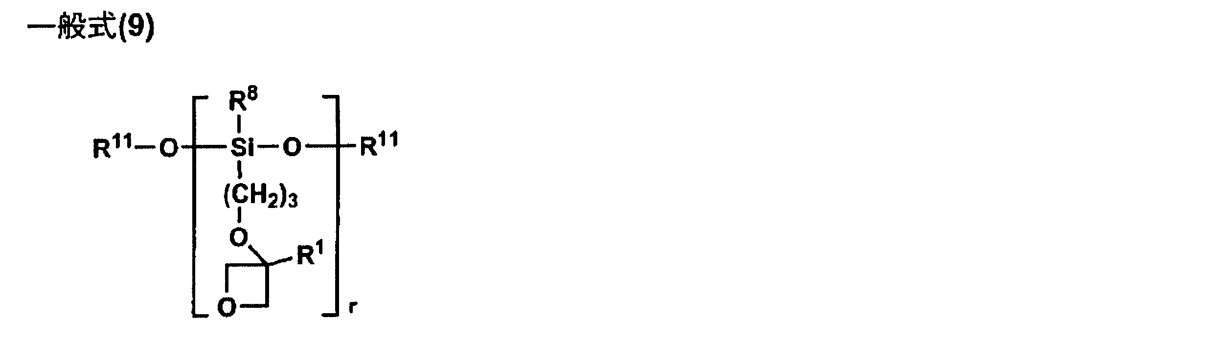
ここで、活性光線硬化型インクジェットインクには、分子量が250未満である光重合性化合物が一部含まれてもよい。ただし、分子量が250未満である光重合性化合物の量は、活性光線硬化型インクジェットインクの全質量に体して30質量%未満であることが好ましく、より好ましくは20質量%未満である。分子量が250未満である光重合性化合物の量が30質量%未満であると、インクの脱気時に揮発する成分の量が少なくなる。その結果、画像出力物の硬化性にムラ等が生じ難くなる。 Other Photopolymerizable Compound Here, the actinic ray curable inkjet ink may contain a part of the photopolymerizable compound having a molecular weight of less than 250. However, the amount of the photopolymerizable compound having a molecular weight of less than 250 is preferably less than 30% by mass, more preferably less than 20% by mass based on the total mass of the actinic ray curable inkjet ink. When the amount of the photopolymerizable compound having a molecular weight of less than 250 is less than 30% by mass, the amount of components that volatilize when the ink is deaerated decreases. As a result, unevenness or the like hardly occurs in the curability of the image output product.
1,4-ブタンジオールジ(メタ)アクリレート、1,6-ヘキサンジオールジアクリレート、ネオペンチルグリコールジ(メタ)アクリレート等の二官能モノマー;等が含まれる。 The photopolymerizable compound having a molecular weight of less than 250 is particularly preferably an unsaturated carboxylic acid ester compound, and may be, for example, a monomer of a (meth) acrylate compound or an oligomer thereof. Examples of (meth) acrylate monomers having a molecular weight of less than 250 include isoamyl (meth) acrylate, lauryl acrylate, octyl (meth) acrylate, decyl (meth) acrylate, 2-hydroxybutyl (meth) acrylate, butoxyethyl (meth) Acrylate, ethoxydiethylene glycol (meth) acrylate, methoxydiethylene glycol (meth) acrylate, methoxypropylene glycol (meth) acrylate, phenoxyethyl (meth) acrylate, tetrahydrofurfuryl (meth) acrylate, isobornyl (meth) acrylate, 2-hydroxyethyl ( (Meth) acrylate, 2-hydroxypropyl (meth) acrylate, 2-hydroxy-3-phenoxypropyl (meth) acrylate, 2- Meth) acryloyloxyethyl succinic acid, monofunctional monomers such as t- butyl cyclohexyl (meth) acrylate;
Bifunctional monomers such as 1,4-butanediol di (meth) acrylate, 1,6-hexanediol diacrylate, neopentyl glycol di (meth) acrylate, and the like.
エチレングリコールジビニルエーテル、ジエチレングリコールジビニルエーテル、トリエチレングリコールジビニルエーテル、プロピレングリコールジビニルエーテル、ジプロピレングリコールジビニルエーテル、ブタンジオールジビニルエーテル、ヘキサンジオールジビニルエーテル、シクロヘキサンジメタノールジビニルエーテル、トリメチロールプロパントリビニルエーテル等のジまたはトリビニルエーテル化合物等が含まれる。これらのビニルエーテル化合物のうち、硬化性や密着性などを考慮すると、ジまたはトリビニルエーテル化合物が好ましい。 In addition, the photopolymerizable compound having a molecular weight of less than 250 may be a cationic polymerizable compound as described above. Examples of cationically polymerizable compounds having a molecular weight of less than 250 include ethyl vinyl ether, n-butyl vinyl ether, isobutyl vinyl ether, cyclohexyl vinyl ether, hydroxybutyl vinyl ether, 2-ethylhexyl vinyl ether, cyclohexanedimethanol monovinyl ether, n-propyl vinyl ether, isopropyl vinyl ether. Monovinyl ether compounds such as isopropenyl ether-o-propylene carbonate, dodecyl vinyl ether, diethylene glycol monovinyl ether;
Diethylene glycol divinyl ether, diethylene glycol divinyl ether, triethylene glycol divinyl ether, propylene glycol divinyl ether, dipropylene glycol divinyl ether, butanediol divinyl ether, hexanediol divinyl ether, cyclohexane dimethanol divinyl ether, trimethylolpropane trivinyl ether, etc. Or a trivinyl ether compound etc. are contained. Of these vinyl ether compounds, di- or trivinyl ether compounds are preferred in view of curability and adhesion.
活性光線硬化型インクジェットインクに含まれる色材は、染料または顔料でありうるが、耐候性の良好な画像が得られやすいことなどから、顔料が好ましい。顔料は、特に限定されないが、例えばカラーインデックスに記載される下記番号の有機顔料または無機顔料でありうる。 <About color materials>
The color material contained in the actinic ray curable ink-jet ink can be a dye or a pigment, but a pigment is preferable because an image having good weather resistance can be easily obtained. The pigment is not particularly limited, and may be, for example, an organic pigment or an inorganic pigment having the following numbers described in the color index.
活性光線硬化型インクジェットインクには、顔料の分散性を高めるために、顔料分散剤がさらに含まれてもよい。顔料分散剤の例には、水酸基含有カルボン酸エステル、長鎖ポリアミノアマイドと高分子量酸エステルの塩、高分子量ポリカルボン酸の塩、長鎖ポリアミノアマイドと極性酸エステルの塩、高分子量不飽和酸エステル、高分子共重合物、変性ポリウレタン、変性ポリアクリレート、ポリエーテルエステル型アニオン系活性剤、ナフタレンスルホン酸ホルマリン縮合物塩、芳香族スルホン酸ホルマリン縮合物塩、ポリオキシエチレンアルキル燐酸エステル、ポリオキシエチレンノニルフェニルエーテル、およびステアリルアミンアセテート等が含まれる。顔料分散剤の市販品の例には、Avecia社のSolsperseシリーズや、味の素ファインテクノ社のPBシリーズ(例えばアジスパーPB824など)が含まれる。 <About pigment dispersant>
The actinic ray curable inkjet ink may further contain a pigment dispersant in order to enhance the dispersibility of the pigment. Examples of pigment dispersants include hydroxyl group-containing carboxylic acid esters, salts of long chain polyaminoamides and high molecular weight acid esters, salts of high molecular weight polycarboxylic acids, salts of long chain polyaminoamides and polar acid esters, high molecular weight unsaturated acids. Ester, polymer copolymer, modified polyurethane, modified polyacrylate, polyether ester type anionic activator, naphthalenesulfonic acid formalin condensate salt, aromatic sulfonic acid formalin condensate salt, polyoxyethylene alkyl phosphate ester, polyoxy Ethylene nonylphenyl ether, stearylamine acetate and the like are included. Examples of commercially available pigment dispersants include Avecia's Solsperse series and Ajinomoto Fine Techno's PB series (for example, Azisper PB824).
活性光線硬化型インクジェットインクに含まれる光重合開始剤には、分子内結合開裂型と分子内水素引き抜き型とがある。分子内結合開裂型の光重合開始剤の例には、ジエトキシアセトフェノン、2-ヒドロキシ-2-メチル-1-フェニルプロパン-1-オン、ベンジルジメチルケタール、1-(4-イソプロピルフェニル)-2-ヒドロキシ-2-メチルプロパン-1-オン、4-(2-ヒドロキシエトキシ)フェニル-(2-ヒドロキシ-2-プロピル)ケトン、1-ヒドロキシシクロヘキシル-フェニルケトン、2-メチル-2-モルホリノ(4-チオメチルフェニル)プロパン-1-オン、2-ベンジル-2-ジメチルアミノ-1-(4-モルホリノフェニル)-ブタノン等のアセトフェノン系;ベンゾイン、ベンゾインメチルエーテル、ベンゾインイソプロピルエーテル等のベンゾイン類;2,4,6-トリメチルベンゾインジフェニルホスフィンオキシド等のアシルホスフィンオキシド系;ベンジルおよびメチルフェニルグリオキシエステル等が含まれる。 <About photopolymerization initiator>
Photopolymerization initiators contained in the actinic ray curable ink jet ink include an intramolecular bond cleavage type and an intramolecular hydrogen abstraction type. Examples of intramolecular bond cleavage type photopolymerization initiators include diethoxyacetophenone, 2-hydroxy-2-methyl-1-phenylpropan-1-one, benzyldimethyl ketal, 1- (4-isopropylphenyl) -2 -Hydroxy-2-methylpropan-1-one, 4- (2-hydroxyethoxy) phenyl- (2-hydroxy-2-propyl) ketone, 1-hydroxycyclohexyl-phenylketone, 2-methyl-2-morpholino (4 Acetophenones such as -thiomethylphenyl) propan-1-one and 2-benzyl-2-dimethylamino-1- (4-morpholinophenyl) -butanone; benzoins such as benzoin, benzoin methyl ether and benzoin isopropyl ether; 2 , 4,6-Trimethylbenzoindiphenylphosphine Acylphosphine oxide, such as Sid; as benzyl and methyl phenylglyoxylate esters include.
活性光線硬化型インクジェットインクには、ワックスがさらに含まれてもよい。ワックスは、通常、疎水性基を有することから、疎水性が高い顔料表面と相互作用しやすい。したがって、ワックスが含まれると、活性光線硬化型インクジェットインクの液体成分が顔料表面に濡れやすくなり、顔料表面の気泡核が除去されやすくなる。そのような、ワックスが含まれる活性光線硬化型インクジェットインクを加熱減圧下で脱気すると、インク中の気泡がより除去されやすくなる。また、インク液滴にワックスが含まれると、記録媒体上に着弾後のインク液滴が高粘度になり、過度に濡れ広がらないため、インク液滴表面への酸素の溶け込みも少なくなる。したがって、画像出力物の硬化性が一層高まる。 <About wax>
The actinic ray curable inkjet ink may further contain a wax. Since the wax usually has a hydrophobic group, the wax tends to interact with the highly hydrophobic pigment surface. Therefore, when the wax is contained, the liquid component of the actinic radiation curable inkjet ink is easily wetted on the pigment surface, and the bubble nuclei on the pigment surface are easily removed. When such actinic ray curable ink-jet ink containing wax is deaerated under heating and reduced pressure, bubbles in the ink are more easily removed. In addition, when the ink droplet contains wax, the ink droplet after landing on the recording medium has a high viscosity and does not spread excessively so that oxygen does not dissolve on the surface of the ink droplet. Accordingly, the curability of the image output product is further increased.
脂肪族ケトン化合物;
脂肪族エステル化合物;
パラフィンワックス、マイクロクリスタリンワックス、ペトロラクタム等の石油系ワックス;
キャンデリラワックス、カルナウバワックス、ライスワックス、木ロウ、ホホバ油、ホホバ固体ロウ、およびホホバエステル等の植物系ワックス;
ミツロウ、ラノリンおよび鯨ロウ等の動物系ワックス;
モンタンワックス、および水素化ワックス等の鉱物系ワックス;
硬化ヒマシ油または硬化ヒマシ油誘導体;
モンタンワックス誘導体、パラフィンワックス誘導体、マイクロクリスタリンワックス誘導体またはポリエチレンワックス誘導体等の変性ワックス;
ベヘン酸、アラキジン酸、ステアリン酸、パルミチン酸、ミリスチン酸、ラウリン酸、オレイン酸、およびエルカ酸等の高級脂肪酸;
ステアリルアルコール、ベヘニルアルコール等の高級アルコール;
12-ヒドロキシステアリン酸等のヒドロキシステアリン酸;
12-ヒドロキシステアリン酸誘導体;ラウリン酸アミド、ステアリン酸アミド、ベヘン酸アミド、オレイン酸アミド、エルカ酸アミド、リシノール酸アミド、12-ヒドロキシステアリン酸アミド等の脂肪酸アミド(例えば日本化成社製 ニッカアマイドシリーズ、伊藤製油社製 ITOWAXシリーズ、花王社製 FATTYAMIDシリーズ等);
N-ステアリルステアリン酸アミド、N-オレイルパルミチン酸アミド等のN-置換脂肪酸アミド;
N,N’-エチレンビスステアリルアミド、N,N’-エチレンビス-12-ヒドロキシステアリルアミド、およびN,N’-キシリレンビスステアリルアミド等の特殊脂肪酸アミド;
ドデシルアミン、テトラデシルアミンまたはオクタデシルアミンなどの高級アミン;
ステアリルステアリン酸、オレイルパルミチン酸、グリセリン脂肪酸エステル、ソルビタン脂肪酸エステル、プロピレングリコール脂肪酸エステル、エチレングリコール脂肪酸エステル、ポリオキシエチレン脂肪酸エステル等の脂肪酸エステル化合物(例えば日本エマルジョン社製 EMALLEXシリーズ、理研ビタミン社製 リケマールシリーズ、理研ビタミン社製 ポエムシリーズ等);
ショ糖ステアリン酸、ショ糖パルミチン酸等のショ糖脂肪酸のエステル(例えばリョートーシュガーエステルシリーズ 三菱化学フーズ社製);
ポリエチレンワックス、α-オレフィン無水マレイン酸共重合体ワックス等の合成ワックス(Baker-Petrolite社製 UNILINシリーズ等);
ダイマー酸;
ダイマージオール(CRODA社製 PRIPORシリーズ等);
ステアリン酸イヌリン等の脂肪酸イヌリン;
パルミチン酸デキストリン、ミリスチン酸デキストリン等の脂肪酸デキストリン(千葉製粉社製 レオパールシリーズ等);
ベヘン酸エイコサン二酸グリセリル;
ベヘン酸エイコサンポリグリセリル(日清オイリオ社製 ノムコートシリーズ等);
N-ラウロイル-L-グルタミン酸ジブチルアミド、N-(2-エチルヘキサノイル)-L-グルタミン酸ジブチルアミド等のアミド化合物(味の素ファインテクノより入手可能);
1,3:2,4-ビス-O-ベンジリデン-D-グルシトール(ゲルオールD 新日本理化より入手可能)等のジベンジリデンソルビトール類;
特開2005-126507号公報、特開2005-255821号公報および特開2010-111790号公報に記載の低分子オイルワックス;等が含まれる。 Examples of such waxes include
An aliphatic ketone compound;
Aliphatic ester compounds;
Petroleum waxes such as paraffin wax, microcrystalline wax, petrolactam;
Plant waxes such as candelilla wax, carnauba wax, rice wax, wood wax, jojoba oil, jojoba solid wax, and jojoba ester;
Animal waxes such as beeswax, lanolin and whale wax;
Mineral waxes such as montan wax and hydrogenated wax;
Hydrogenated castor oil or hydrogenated castor oil derivative;
Modified waxes such as montan wax derivatives, paraffin wax derivatives, microcrystalline wax derivatives or polyethylene wax derivatives;
Higher fatty acids such as behenic acid, arachidic acid, stearic acid, palmitic acid, myristic acid, lauric acid, oleic acid, and erucic acid;
Higher alcohols such as stearyl alcohol and behenyl alcohol;
Hydroxystearic acid such as 12-hydroxystearic acid;
12-hydroxystearic acid derivatives; fatty acid amides such as lauric acid amide, stearic acid amide, behenic acid amide, oleic acid amide, erucic acid amide, ricinoleic acid amide, 12-hydroxystearic acid amide (for example, Nikka Amide series manufactured by Nippon Kasei Co., Ltd.) ITOWAX series manufactured by Ito Oil Co., Ltd., FATTYAMID series manufactured by Kao Corporation, etc.);
N-substituted fatty acid amides such as N-stearyl stearic acid amide, N-oleyl palmitic acid amide;
Special fatty acid amides such as N, N′-ethylenebisstearylamide, N, N′-ethylenebis-12-hydroxystearylamide, and N, N′-xylylenebisstearylamide;
Higher amines such as dodecylamine, tetradecylamine or octadecylamine;
Stearyl stearic acid, oleyl palmitic acid, glycerin fatty acid ester, sorbitan fatty acid ester, propylene glycol fatty acid ester, ethylene glycol fatty acid ester, polyoxyethylene fatty acid ester, etc. Marl series, RIKEN VITAMIN POM series, etc.);
Esters of sucrose fatty acids such as sucrose stearic acid and sucrose palmitic acid (eg Ryoto Sugar Ester series manufactured by Mitsubishi Chemical Foods);
Synthetic waxes such as polyethylene wax and α-olefin maleic anhydride copolymer wax (UNILIN series manufactured by Baker-Petrolite);
Dimer acid;
Dimer diol (such as PRIDA series manufactured by CRODA);
Fatty acid inulins such as inulin stearate;
Fatty acid dextrins such as dextrin palmitate and dextrin myristate (such as Leopard series manufactured by Chiba Flour Mills);
Glyceryl behenate eicosane diacid;
Eicosane polyglyceryl behenate (Nomshin Eulio Co., Ltd. Nomucoat series, etc.);
Amide compounds such as N-lauroyl-L-glutamic acid dibutylamide and N- (2-ethylhexanoyl) -L-glutamic acid dibutylamide (available from Ajinomoto Fine Techno);
Dibenzylidene sorbitols such as 1,3: 2,4-bis-O-benzylidene-D-glucitol (available from Gelol D Shin Nippon Rika);
And low molecular oil waxes described in JP-A-2005-126507, JP-A-2005-255821 and JP-A-2010-11117.
一般式(G1):R1-CO-R2
一般式(G2):R3-COO-R4 Among these, waxes having polar groups such as —OH and —COOH at the end of the alkyl chain, such as fatty acid amide, are not sufficiently stable in the sol-like ink, and precipitate or layer separation occurs. Therefore, an aliphatic ketone compound or an aliphatic ester compound is preferable. That is, the wax is preferably a compound represented by the following general formula (G1) or (G2).
General formula (G1): R 1 —CO—R 2
General formula (G2): R 3 —COO—R 4
活性光線硬化型インクジェットインクには、必要に応じて他の成分がさらに含まれてもよい。他の成分は、各種添加剤や他の樹脂等であってよい。添加剤の例には、界面活性剤、レベリング添加剤、マット剤、紫外線吸収剤、赤外線吸収剤、抗菌剤、インクの保存安定性を高めるための塩基性化合物等も含まれる。塩基性化合物の例には、塩基性アルカリ金属化合物、塩基性アルカリ土類金属化合物、アミンなどの塩基性有機化合物などが含まれる。他の樹脂の例には、硬化膜の物性を調整するための樹脂などが含まれ、例えばポリエステル系樹脂、ポリウレタン系樹脂、ビニル系樹脂、アクリル系樹脂、ゴム系樹脂、およびワックス類等が含まれる。 <About other ingredients>
The actinic ray curable inkjet ink may further contain other components as necessary. Other components may be various additives, other resins, and the like. Examples of the additive include a surfactant, a leveling additive, a matting agent, an ultraviolet absorber, an infrared absorber, an antibacterial agent, and a basic compound for enhancing the storage stability of the ink. Examples of basic compounds include basic alkali metal compounds, basic alkaline earth metal compounds, basic organic compounds such as amines, and the like. Examples of other resins include resins for adjusting the physical properties of the cured film, such as polyester resins, polyurethane resins, vinyl resins, acrylic resins, rubber resins, and waxes. It is.
活性光線硬化型インクジェットインクは、インク液滴の吐出性や後述の脱気工程における脱気性を高めるために、高温下におけるインクの粘度が一定以下であることが好ましい。具体的には、活性光線硬化型インクジェットインクの、80℃における粘度が3~20mPa・sであることが好ましい。一方、活性光線硬化型インクジェットインクは、隣り合うドットの合一を抑制するために、着弾後の常温下におけるインクの粘度が一定以上であることが好ましい。具体的には、25℃におけるインクの粘度は1000mPa・s以上であることが好ましい。 <Physical properties of ink>
The actinic ray curable ink-jet ink preferably has a viscosity of the ink at a high temperature or less in order to improve the discharge property of ink droplets and the deaeration property in the deaeration process described later. Specifically, the viscosity of the actinic ray curable inkjet ink at 80 ° C. is preferably 3 to 20 mPa · s. On the other hand, the actinic ray curable inkjet ink preferably has a viscosity of the ink at a certain temperature or higher after landing in order to suppress coalescence of adjacent dots. Specifically, the viscosity of the ink at 25 ° C. is preferably 1000 mPa · s or more.
本発明のインクジェット記録方法は、少なくとも(1)インクジェット記録装置内の減圧空間にインクジェットインクを導入し、インク温度50℃以上120℃未満で前記インクジェットインクを脱気する工程、(2)脱気された活性光線硬化型インクジェットインクのインク液滴を、記録ヘッドから吐出して記録媒体上に着弾させる工程、および(3)記録媒体上に着弾したインク液滴に活性光線を照射し、インク液滴を硬化させる工程を含む。活性光線硬化型インクジェットインクは、前述の活性光線硬化型インクジェットインクでありうる。 2. Inkjet recording method The inkjet recording method of the present invention comprises at least (1) a step of introducing an inkjet ink into a decompressed space in an inkjet recording apparatus and degassing the inkjet ink at an ink temperature of 50 ° C. or more and less than 120 ° C., (2) A step of ejecting the degassed actinic ray curable inkjet ink droplets from the recording head and landing on the recording medium; and (3) irradiating the ink droplets landing on the recording medium with actinic rays, Curing the ink droplets. The actinic ray curable inkjet ink may be the actinic ray curable inkjet ink described above.
インクジェット記録装置内の活性光線硬化型インクジェットインクを、インクジェット記録装置内の減圧空間内で脱気する。このときのインク温度は50℃以上120℃未満とする。当該工程では、空間全体を減圧してもよく、空間の一部のみ減圧してもよい。インクの脱気方法としては、例えば(i)インクを減圧タンク内に導入し、インク中から気泡を除去する方法、もしくは(ii)空間内に中空糸を配置し、中空糸内を減圧してインク中から気泡を除去する方法が挙げられる。以下、これらの方法を説明するが、本発明の方法はこれらに限定されるものではない。 <About (1) process>
The actinic ray curable ink-jet ink in the ink-jet recording apparatus is degassed in a reduced pressure space in the ink-jet recording apparatus. The ink temperature at this time is 50 ° C. or higher and lower than 120 ° C. In this step, the entire space may be decompressed, or only a part of the space may be decompressed. As a method for degassing ink, for example, (i) a method of introducing ink into a decompression tank and removing bubbles from the ink, or (ii) a hollow fiber is disposed in the space, and the inside of the hollow fiber is decompressed. There is a method of removing bubbles from the ink. Hereinafter, although these methods are demonstrated, the method of this invention is not limited to these.
インクの脱気方法の一つに、減圧タンク内にインクを導入する方法が挙げられる。減圧タンク内でのインクの温度は50~120℃であり、好ましくは70~110℃であり、さらに好ましくは80~100℃である。減圧タンク内でのインク温度が上記範囲であると、インクの粘度が低くなり、インクから気泡が除去されやすくなる。減圧タンク内のインク温度を所望の範囲に制御する方法は特に制限されず、減圧タンクの外部、または内部に設けられたヒーター等によってインク温度を調整してもよい。また、減圧タンクに導入するインクを予め加温しておき、当該インクを導入することで、タンク内の温度を、所望の温度に調整してもよい。インク温度は、減圧タンクに導入前のインク温度及び減圧タンクから排出後のインク温度のいずれか一方が上記温度範囲を満たせばよく、両方が上記温度範囲を満たすことが好ましい。 Method (i) One method of degassing ink is a method of introducing ink into a decompression tank. The temperature of the ink in the vacuum tank is 50 to 120 ° C., preferably 70 to 110 ° C., and more preferably 80 to 100 ° C. When the ink temperature in the decompression tank is within the above range, the viscosity of the ink becomes low and bubbles are easily removed from the ink. The method for controlling the ink temperature in the decompression tank to a desired range is not particularly limited, and the ink temperature may be adjusted by a heater or the like provided outside or inside the decompression tank. Alternatively, the temperature in the tank may be adjusted to a desired temperature by preheating the ink to be introduced into the decompression tank and introducing the ink. As for the ink temperature, any one of the ink temperature before being introduced into the decompression tank and the ink temperature after being discharged from the decompression tank may satisfy the above temperature range, and it is preferable that both satisfy the above temperature range.
インクの脱気方法の他の方法として、インクジェット記録装置に内蔵された中空糸により脱気する方法が挙げられる。ここで、中空糸は、気体は透過するが、液体は透過しない中空状(ストロー状)の糸である。中空糸の材質の例には、ポリプロピレン、ポリ(4-メチル-1-ペンテン)などのポリオレフィン系樹脂;ポリジメチルシロキサンやその共重合体などのシリコーン系樹脂;PTFE、フッ化ビニリデンなどのフッ素系樹脂などが含まれる。なかでも、加熱により表面エネルギーが大きくなりやすく、脱気効率を高めやすい点などから、シリコーン系樹脂やフッ素系樹脂が好ましい。 Method (ii) As another method of degassing the ink, there is a method of degassing with a hollow fiber built in the ink jet recording apparatus. Here, the hollow fiber is a hollow (straw-shaped) yarn that allows gas to pass through but does not allow liquid to pass through. Examples of hollow fiber materials include polyolefin resins such as polypropylene and poly (4-methyl-1-pentene); silicone resins such as polydimethylsiloxane and copolymers thereof; fluorine resins such as PTFE and vinylidene fluoride Resin etc. are included. Of these, silicone resins and fluororesins are preferred from the viewpoint that the surface energy is easily increased by heating and the deaeration efficiency is easily increased.
前述のように脱気された活性光線硬化型インクジェットインクのインク液滴を記録ヘッドから吐出する。吐出直前の活性光線硬化型インクジェットインクは、インク液滴の射出性を高める観点から、60~100℃、好ましくは60~80℃に加熱されることが好ましい。吐出直前の活性光線硬化型インクジェットインクの温度が低すぎると、インクの粘度が高すぎたり、インクがワックスを含む場合は記録ヘッド内もしくはノズル表面でゲル化したりして、インク液滴の射出性が低下しやすくなる。一方、吐出直前の活性光線硬化型インクジェットインクの温度が高すぎると、インク成分が劣化しやすくなる。 <(2) Process>
Ink droplets of the actinic ray curable inkjet ink deaerated as described above are ejected from the recording head. The actinic ray curable inkjet ink immediately before ejection is preferably heated to 60 to 100 ° C., preferably 60 to 80 ° C., from the viewpoint of enhancing the ejection properties of the ink droplets. If the temperature of the actinic radiation curable inkjet ink immediately before ejection is too low, the ink viscosity is too high, or if the ink contains wax, it will gel in the recording head or on the nozzle surface, causing ink droplet ejection properties Tends to decrease. On the other hand, if the temperature of the actinic ray curable inkjet ink immediately before ejection is too high, the ink component tends to deteriorate.
記録媒体に着弾したインク液滴に活性光線を照射することで、インク液滴に含まれる光重合性化合物を架橋または重合させてインク液滴を硬化させる。 <(3) Process>
By irradiating the ink droplet landed on the recording medium with an actinic ray, the photopolymerizable compound contained in the ink droplet is crosslinked or polymerized to cure the ink droplet.
本発明のインクジェット記録方法は、活性光線硬化型インクジェット方式のインクジェット記録装置を用いて行うことができる。 3. Inkjet recording apparatus The inkjet recording method of the present invention can be performed using an actinic ray curable inkjet recording apparatus.
ヘッドキャリッジ13は、記録媒体20の全幅を覆うように固定配置されており、複数の記録ヘッド11を収容する。各ヘッドキャリッジ13は、互いに異なる色の記録ヘッド11を収容している。 <Head carriage>
The
インクタンク17は、ヘッドキャリッジ13に、インク流路15と脱気モジュール19を介して接続されている。インク流路15は、インクタンク17中のインクをヘッドキャリッジ13に供給する経路である。インク液滴を安定して吐出するため、インクタンク17、インク流路15、ヘッドキャリッジ13および記録ヘッド11のインクを所定の温度に加熱できるようになっている。 <Ink tank and ink flow path>
The
脱気モジュール19は、インクタンク17及びヘッドキャリッジ13とそれぞれインク流路15を介して接続されている。インクタンク17から供給されたインクは、脱気モジュール19で脱気されてから、ヘッドキャリッジ13に送られる。 <Deaeration module>
The
インクは、インク導入口33からハウジング本体27A内に導入され、中央孔39を流通する。中央孔39を流通するインクは、その側壁面から中空糸の集合体25に流入し(矢印X);中空糸31の外表面を流通する。一方、中空糸31の中空内(孔31A内)は減圧されているため、インク中の気泡が中空糸31を透過して中空内(孔31A内)に吸引される。中空糸31の中空内に吸引された気泡は、中空糸31の他端から排出され(矢印Y参照)、吸引口35を介して排出される。 In the hollow
Ink is introduced into the
活性光線照射部21は、記録媒体20の全幅を覆い、かつ記録媒体の搬送方向についてヘッドキャリッジ13の下流側に配置されている。活性光線照射部21は、記録ヘッド11により吐出されて、記録媒体に着弾した液滴に光を照射し、液滴を硬化させる。 <Actinic ray irradiation part>
The actinic
以下、ライン記録方式のインクジェット記録装置10を用いた画像形成方法を説明する。記録媒体20を、インクジェット記録装置10のヘッドキャリッジ13と温度制御部23との間に搬送する。一方で、記録媒体20を、温度制御部23により所定の温度に調整する。 <Image forming method>
Hereinafter, an image forming method using the line recording type
図7は、シリアル記録方式のインクジェット記録装置60の要部の構成の一例を示す図である。図7に示されるように、インクジェット記録装置60は、記録媒体の全幅を覆うように固定配置されたヘッドキャリッジ13の代わりに、記録媒体の全幅よりも狭い幅に設けられ、複数の記録ヘッド61を収容するヘッドキャリッジ63と、ヘッドキャリッジ63を記録媒体20の幅方向に可動させるためのガイド部65とを有する以外は図6とほぼ同様に構成されうる。図6と同一または類似の機能を有する部材には、同一の符号を付した。 <Other image forming apparatus>
FIG. 7 is a diagram illustrating an example of a configuration of a main part of the serial recording type
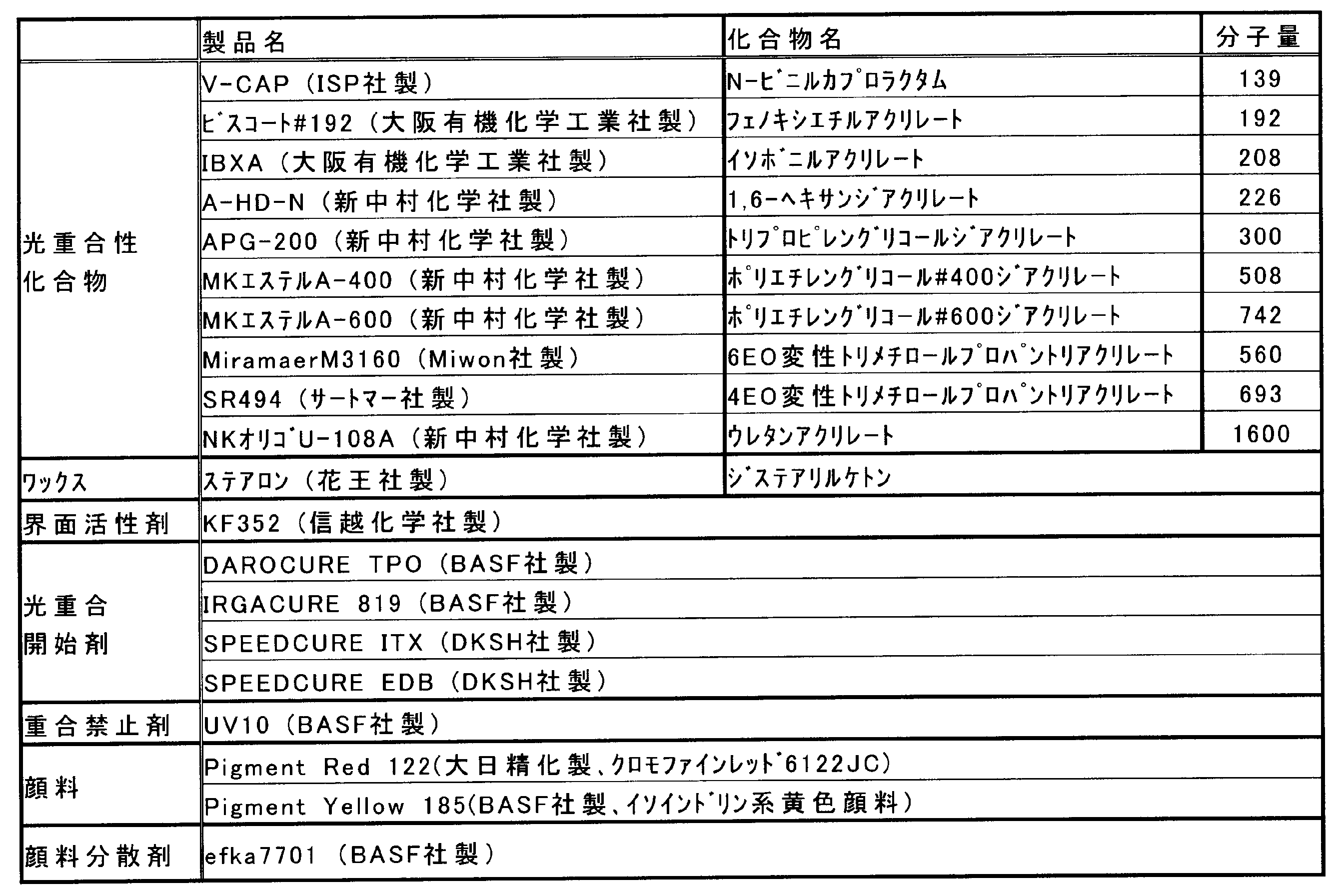
(イエロー顔料分散液)
ステンレスビーカーに、efka7701 8質量部と、APG-200 71質量部とを入れ、65℃のホットプレート上で加熱しながら1時間加熱攪拌して、溶解させた。当該混合液を室温まで冷却した後、黄色顔料Pigment Yellow 185 20質量部加えた。当該混合液を、直径0.5mmのジルコニアビーズ200gとともにガラス瓶に入れて密栓し、ペイントシェーカーにて8時間分散処理した。その後、ジルコニアビーズを除去して、イエロー顔料分散液を調製した。 <Preparation of pigment dispersion>
(Yellow pigment dispersion)
8 parts by mass of efka7701 and 71 parts by mass of APG-200 were placed in a stainless beaker, and dissolved by heating and stirring for 1 hour while heating on a 65 ° C. hot plate. After cooling the mixed solution to room temperature, 20 parts by mass of yellow pigment Pigment Yellow 185 was added. The mixed solution was put in a glass bottle together with 200 g of zirconia beads having a diameter of 0.5 mm, sealed, and dispersed for 8 hours using a paint shaker. Thereafter, the zirconia beads were removed to prepare a yellow pigment dispersion.
顔料を、マゼンタ顔料Pigment Red 122に変更した以外は、イエロー顔料分散液と同様に、マゼンタ顔料分散液を調製した。 (Magenta pigment dispersion)
A magenta pigment dispersion was prepared in the same manner as the yellow pigment dispersion, except that the pigment was changed to magenta pigment Pigment Red 122.
<イエローインクの調製>
顔料として、前述のイエロー顔料分散液を12.0質量部と;光重合性化合物として、APG-200を8.0質量部、MKエステルA-400を10.0質量部、MKエステルA-600を10.0質量部、Miramaer M3160を28.8質量部、SR494を20.0質量部と;界面活性剤として、KF352(信越化学社製)を0.05質量部と;光重合開始剤として、DAROCURE TPOを4.0質量部、IRGACURE 819を2.0質量部、SPEEDCURE ITX(DKSH社製)を2.0質量部、SPEEDCURE EDB(DKSH社製)を3.0質量部と;重合禁止剤として、UV10(BASF社製)を0.2質量部と;を混合して、80℃で攪拌した。得られた溶液をADVATEC社製テフロン(登録商標)3μmメンブランフィルターで濾過してイエローインクを調製した。 [Example 1]
<Preparation of yellow ink>
As a pigment, 12.0 parts by mass of the aforementioned yellow pigment dispersion; 8.0 parts by mass of APG-200, 10.0 parts by mass of MK ester A-400, and MK ester A-600 as photopolymerizable compounds 10.0 parts by mass, Miramaer M3160 28.8 parts by mass, SR494 20.0 parts by mass; surfactant, KF352 (manufactured by Shin-Etsu Chemical Co., Ltd.) 0.05 part by mass; photopolymerization initiator DAROCURE TPO is 4.0 parts by mass, IRGACURE 819 is 2.0 parts by mass, SPEEDCURE ITX (manufactured by DKSH) is 2.0 parts by mass, and SPEEDCURE EDB (manufactured by DKSH) is 3.0 parts by mass; As an agent, 0.2 part by mass of UV10 (manufactured by BASF) was mixed and stirred at 80 ° C. The obtained solution was filtered through a Teflon (registered trademark) 3 μm membrane filter manufactured by ADVATEC to prepare a yellow ink.
表2に示される組成に変更した以外は、イエローインクと同様にマゼンタインクを調製した。 <Preparation of magenta ink>
A magenta ink was prepared in the same manner as the yellow ink except that the composition shown in Table 2 was changed.
図6に示されるライン記録方式のインクジェット記録装置を用いて、単色画像を形成した。インクジェット記録装置のインク供給系は、インクタンク、供給パイプ、脱気モジュール、ヘッド直前のサブインクタンク、フィルター付き配管、およびピエゾヘッド(記録ヘッド)がこの順に連通して構成されている。そして、上記イエローインク及びマゼンタインクをそれぞれインクジェット装置のインクタンクに供給した。そして、インクジェット記録装置のインクタンクから記録ヘッドまでを90℃に加熱した。また、脱気モジュール内の空間を97kPaまで減圧した。脱気モジュールへのインクの供給速度は200cc/minとした。 <Image forming method>
A monochromatic image was formed using the line recording type inkjet recording apparatus shown in FIG. The ink supply system of the ink jet recording apparatus includes an ink tank, a supply pipe, a deaeration module, a sub ink tank immediately before the head, a pipe with a filter, and a piezo head (recording head) in this order. Then, the yellow ink and the magenta ink were respectively supplied to the ink tank of the ink jet apparatus. Then, the ink tank from the ink jet recording apparatus to the recording head was heated to 90 ° C. Moreover, the space in the deaeration module was decompressed to 97 kPa. The ink supply speed to the deaeration module was 200 cc / min.
脱気モジュールは、図2に示されるような、円筒状の減圧タンク70’内に、インクの流路73が螺旋状に形成された構造のものとした。流路73は、フッ素樹脂からなる凹状の部材(凹部の断面形状:半円状)とした。また、流路上面の総面積(流路を流れるインクと空気層との界面の総面積)は、300cm2とした。減圧タンク70’内のインク温度は、減圧タンク70’の外周に設置したジャケットヒーター(図示せず)及び減圧タンク70’のインク導入口70F近傍に設けた加熱手段(図示せず)で調整した。このとき、減圧タンク70’内のインク温度(減圧タンク70’に導入するインクの温度)は90℃とした。一方、減圧タンク70’内の真空度は減圧ポンプ72で調整し、-90kPaとした。 (Deaeration module)
The deaeration module has a structure in which an
前述のイエローインク及びマゼンタインクを用いた画像記録方法について、インク吐出安定性、インクの硬化性、及び画像出力物の評価を行った。各評価方法は以下の通りである。結果を表2に示す。 <Evaluation>
The image recording method using the yellow ink and magenta ink described above was evaluated for ink ejection stability, ink curability, and image output. Each evaluation method is as follows. The results are shown in Table 2.
前述の記録ヘッドを用いて、液滴量3.5pl、液滴速度7m/sec、射出周波数40kHz、印字率100%となる条件でイエローインクを連続吐出(駆動)させた。そして、駆動開始から1分後、5分後、10分後に射出していないノズル数をカウントした。
◎:欠ノズルの数が2個未満である
○:欠ノズルの数が2個以上10個未満である
△:欠ノズルの数が10個以上50個未満である
×:欠ノズルの数が50個以上である <Evaluation of ink ejection stability>
Using the recording head described above, yellow ink was continuously ejected (driven) under the conditions of a droplet volume of 3.5 pl, a droplet velocity of 7 m / sec, an ejection frequency of 40 kHz, and a printing rate of 100%. The number of nozzles that were not ejected after 1 minute, 5 minutes, and 10 minutes from the start of driving was counted.
◎: The number of missing nozzles is less than 2 ○: The number of missing nozzles is 2 or more and less than 10 Δ: The number of missing nozzles is 10 or more and less than 50 ×: The number of missing nozzles is 50 More than
印刷用コート紙(OK金藤 米坪量104.7g/m2 王子製紙社製)上に、マゼンタインクを9g/m2の付き量で印刷し、マゼンタのベタ画像を形成した。
画像形成後、インクジェット記録装置の下流部に配置したLEDランプ(Heraeus社製、8W/cm2、395nm、water cooled unit)により、印刷用コート紙に紫外線を照射し、インクを硬化させた。紫外線照射時の、LEDランプと印刷用コート紙との距離は、30mmとした。また、紫外線照射時のLEDランプと印刷用コート紙との相対速度は、60m/minとした。 <Ink curability evaluation>
On the coated paper for printing (manufactured by OK KINFUJI rice basis weight 104.7 g / m 2 Oji Paper Co., Ltd.), a magenta ink printed in amount per of 9 g / m 2, to form a solid image of magenta.
After the image formation, the coated paper for printing was irradiated with ultraviolet rays by an LED lamp (manufactured by Heraeus, 8 W / cm 2 , 395 nm, water cooled unit) disposed in the downstream portion of the ink jet recording apparatus to cure the ink. The distance between the LED lamp and the coated paper for printing during UV irradiation was 30 mm. Further, the relative speed between the LED lamp and the coated paper for printing at the time of ultraviolet irradiation was 60 m / min.
◎:色移りがなく、表面のべたつきもなし
○:わずかに色移りがあるが、表面のべたつきはなし
△:わずかに色移りがあり、やや表面のべたつきがあり
×:色移りがあり、さらに表面のべたつきがあり Evaluation of the stickiness on the surface of the printed material was performed by palpating the obtained solid image with a finger. Evaluation of the scratch resistance of the printed material was carried out according to the method described in “JIS standard K5701-1-6.2.3 Friction resistance test”. Coated paper for printing cut to a size of 2 cm 2 (OK Kanto Yonetsubo) Amount of 104.7 g / m 2 manufactured by Oji Paper Co., Ltd.) was placed on the printing surface and rubbed with a load of 800 g, and the degree of color transfer to the coated paper for printing was visually observed to evaluate the curability. went.
◎: No color transfer and no surface stickiness ○: Slight color transfer but no surface stickiness △: Slight color transfer, slightly surface stickiness ×: Color transfer, surface There is stickiness
印刷用コート紙(OK金藤 米坪量104.7g/m2 王子製紙社製)、及びポリプロピレンフィルム(オカモト社製)に、イエローインク及びマゼンタインクをそれぞれ6g/m2の付き量で印刷し、赤色のベタ画像を形成した。画像形成後、インクジェット記録装置の下流部に配置したLEDランプ(Heraeus社製、8W/cm2、395nm、water cooled unit)により、印刷用コート紙に紫外線を照射して、印刷用コート紙に着弾したインクを硬化させた。紫外線照射時の、LEDランプと印刷用コート紙との距離は、30mmとした。また、紫外線照射時のLEDランプと印刷用コート紙との相対速度は、60m/minとした。 <Image quality evaluation>
A yellow ink and a magenta ink are each printed at a weight of 6 g / m 2 on a coated paper for printing (OK Kanito, US basis weight 104.7 g / m 2 manufactured by Oji Paper Co., Ltd.) and a polypropylene film (manufactured by Okamoto). A red solid image was formed. After forming the image, the coated paper for printing is irradiated with ultraviolet rays by an LED lamp (Heraeus, 8 W / cm 2 , 395 nm, water cooled unit) disposed in the downstream part of the inkjet recording apparatus, and landed on the coated paper for printing. The cured ink was cured. The distance between the LED lamp and the coated paper for printing during UV irradiation was 30 mm. Further, the relative speed between the LED lamp and the coated paper for printing at the time of ultraviolet irradiation was 60 m / min.
◎:光沢が均一であり、粒状性が低い
○:光沢がやや不均一であるが、粒状性は低い
△:光沢が不均一であるが、粒状性は低い
×:光沢が不均一であり、粒状性も高い The glossiness of the solid image printed on the coated paper for printing and the polypropylene film was visually evaluated as follows.
◎: Gloss is uniform and graininess is low ○: Gloss is slightly non-uniform, but graininess is low △: Gloss is non-uniform, but graininess is low ×: Gloss is non-uniform, High graininess
イエローインク及びマゼンタインクの組成を、表2に示される組成に変更した以外は実施例1と同様に、イエローインク及びマゼンタインクをそれぞれ調製した。なお、表2の組成を示す数値の単位は「質量部」である。
当該イエローインク及びマゼンタインクを用いて実施例1と同様のインクジェット記録装置で画像出力した。インク吐出安定性、インクの硬化性、及び画像出力物の評価結果を表2に示す。 [Examples 2 to 6]
Yellow ink and magenta ink were respectively prepared in the same manner as in Example 1 except that the compositions of yellow ink and magenta ink were changed to the compositions shown in Table 2. The unit of the numerical value indicating the composition in Table 2 is “part by mass”.
Using the yellow ink and magenta ink, an image was output by the same ink jet recording apparatus as in Example 1. Table 2 shows the ink ejection stability, ink curability, and evaluation results of the image output.

イエローインク及びマゼンタインクの組成を、表3に示される組成に変更した以外は実施例1と同様に、イエローインク及びマゼンタインクをそれぞれ調製した。なお、表3の組成を示す数値の単位は「質量部」である。
当該イエローインク及びマゼンタインクを用いて、実施例1と同様のインクジェット記録装置で画像出力した。ただし、インクジェット記録装置に含まれる減圧脱気モジュール内のインク温度、及び真空度は、表3に示される値とした。各実施例のインク吐出安定性、インクの硬化性、及び画像出力物の評価結果を表3に示す。 [Examples 7 to 11]
A yellow ink and a magenta ink were respectively prepared in the same manner as in Example 1 except that the compositions of the yellow ink and the magenta ink were changed to the compositions shown in Table 3. The unit of the numerical value indicating the composition in Table 3 is “part by mass”.
Using the yellow ink and magenta ink, an image was output by the same ink jet recording apparatus as in Example 1. However, the ink temperature and the degree of vacuum in the vacuum degassing module included in the ink jet recording apparatus were values shown in Table 3. Table 3 shows the evaluation results of the ink ejection stability, ink curability, and image output in each example.

一方、脱気モジュール内のインク温度が高くなると、画質の評価が若干低下した(実施例9)。これは、脱気時に、インク中の成分が揮発しやすくなり、インクの組成が変化しやすくなったと推察される。 Here, when the ink temperature in the vacuum degassing module was lowered, the ejection stability tended to be slightly lowered (Examples 7 and 8). It is presumed that the viscosity of the ink at the time of deaeration is high and the degree of deaeration is low.
On the other hand, when the ink temperature in the deaeration module increased, the evaluation of image quality slightly decreased (Example 9). This is presumed that the components in the ink are easily volatilized and the composition of the ink is easily changed during the deaeration.
イエローインク及びマゼンタインクの組成を、表4に示される組成に変更した以外は実施例1と同様に、イエローインク及びマゼンタインクをそれぞれ調製した。なお、表4の組成を示す数値の単位は「質量部」である。
当該イエローインク及びマゼンタインクを用いて、実施例1と同様のインクジェット記録装置で画像出力した。ただし、インクジェット記録装置に含まれる減圧脱気モジュール内のインク温度、及び真空度は、表3に示される値とした。各実施例のインク吐出安定性、インクの硬化性、及び画像出力物の評価結果を表4に示す。 [Comparative Examples 1 to 6]
A yellow ink and a magenta ink were respectively prepared in the same manner as in Example 1 except that the compositions of the yellow ink and the magenta ink were changed to the compositions shown in Table 4. The unit of the numerical value indicating the composition in Table 4 is “part by mass”.
Using the yellow ink and magenta ink, an image was output by the same ink jet recording apparatus as in Example 1. However, the ink temperature and the degree of vacuum in the vacuum degassing module included in the ink jet recording apparatus were values shown in Table 3. Table 4 shows the evaluation results of the ink ejection stability, ink curability, and image output in each example.
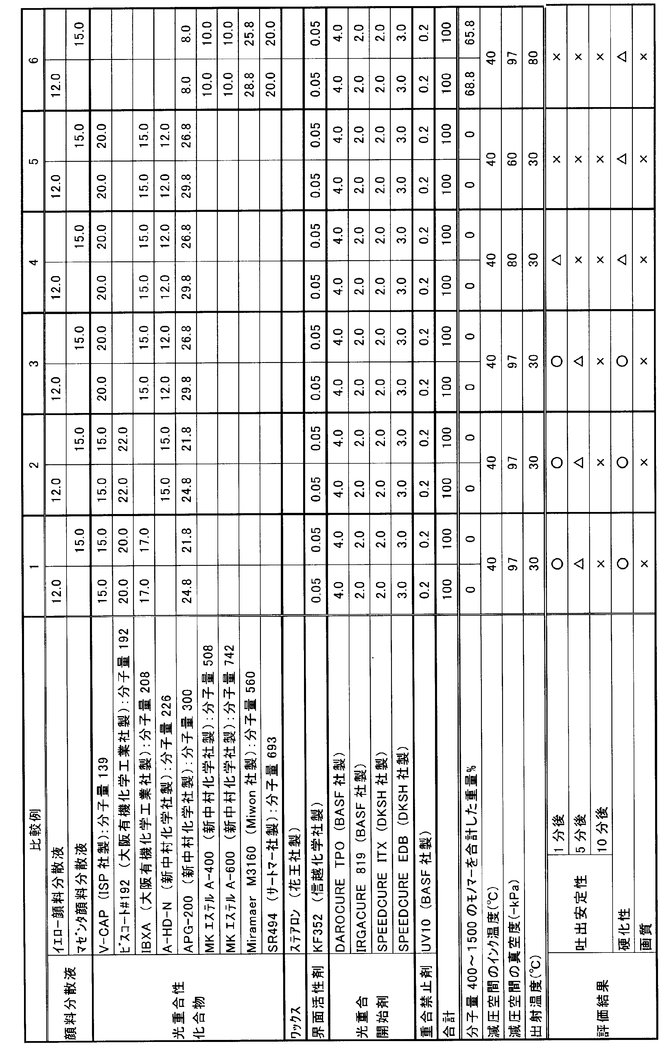
11、61 記録ヘッド
13、63 ヘッドキャリッジ
15 インク流路
17 インクタンク
19 脱気モジュール
20 記録媒体
21 活性光線照射部
23 温度制御部
25、41 中空糸の集合体
27 ハウジング
27A ハウジング本体
29 ジャケットヒータ(加熱手段)
31 中空糸
31A 中空糸の孔
33 インク導入口
35 吸引口
37 インク排出口
39 中央孔
43 多孔ケース
45 導入接続口
47 排出接続口
65 ガイド部
70、70’ 減圧タンク
71 ノズル
72 減圧ポンプ
73 流路
79、79’ 減圧脱気モジュール
80 脱気後のインク
81 空気層
89、89’ 中空糸脱気モジュール
DESCRIPTION OF
DESCRIPTION OF
Claims (5)
- 色材、光重合開始剤、及び分子量が250~1500の範囲内である光重合性化合物を含有する活性光線硬化型インクジェットインクを用いたインクジェット記録方法であって、
インクジェット記録装置内の減圧空間内に前記インクジェットインクを導入し、インク温度50℃以上120℃未満で前記インクジェットインクを脱気する工程と、
脱気された前記インクジェットインクのインク液滴を、記録ヘッドから吐出して記録媒体上に着弾させる工程と、
前記記録媒体上に着弾したインク液滴に活性光線を照射して、前記インク液滴を硬化させる工程と、を含む、インクジェット記録方法。 An inkjet recording method using an actinic ray curable inkjet ink containing a colorant, a photopolymerization initiator, and a photopolymerizable compound having a molecular weight in the range of 250 to 1500,
Introducing the inkjet ink into a decompressed space in the inkjet recording apparatus, and degassing the inkjet ink at an ink temperature of 50 ° C. or more and less than 120 ° C .;
Ejecting ink droplets of the degassed inkjet ink from a recording head and landing on a recording medium;
Irradiating an ink droplet landed on the recording medium with an actinic ray to cure the ink droplet. - 前記光重合性化合物は、分子量が400~1500であり、かつ
前記インクジェットインクが、前記インクジェットインクの総量に対して、前記光重合性化合物を30~70質量%含む、請求項1に記載のインクジェット記録方法。 The inkjet according to claim 1, wherein the photopolymerizable compound has a molecular weight of 400 to 1500, and the inkjet ink contains 30 to 70 mass% of the photopolymerizable compound with respect to a total amount of the inkjet ink. Recording method. - 前記インクジェットインクが、ワックスをさらに含有する、請求項1または2に記載のインクジェット記録方法。 The inkjet recording method according to claim 1 or 2, wherein the inkjet ink further contains a wax.
- 前記脱気工程が、前記空間を真空度-90kPa未満に脱気しながら、前記インクジェットインクを脱気する工程である、請求項1~3のいずれか一項に記載のインクジェット記録方法。 The inkjet recording method according to any one of claims 1 to 3, wherein the degassing step is a step of degassing the inkjet ink while deaerating the space to a degree of vacuum of less than -90 kPa.
- 前記硬化工程が、前記記録媒体と前記活性光線の光源とを相対的に50m/min以上で移動させて、前記インク液滴を硬化させる工程である、請求項1~4のいずれか一項に記載のインクジェット記録方法。
5. The curing process according to claim 1, wherein the curing step is a step of curing the ink droplets by moving the recording medium and the light source of the actinic ray relatively at 50 m / min or more. The inkjet recording method as described.
Priority Applications (3)
| Application Number | Priority Date | Filing Date | Title |
|---|---|---|---|
| EP15761864.6A EP3118011B1 (en) | 2014-03-14 | 2015-03-13 | Ink-jet recording method |
| JP2016507854A JP6471743B2 (en) | 2014-03-14 | 2015-03-13 | Inkjet recording method |
| US15/122,692 US9840086B2 (en) | 2014-03-14 | 2015-03-13 | Ink-jet recording method |
Applications Claiming Priority (2)
| Application Number | Priority Date | Filing Date | Title |
|---|---|---|---|
| JP2014052306 | 2014-03-14 | ||
| JP2014-052306 | 2014-03-14 |
Publications (1)
| Publication Number | Publication Date |
|---|---|
| WO2015137498A1 true WO2015137498A1 (en) | 2015-09-17 |
Family
ID=54071934
Family Applications (1)
| Application Number | Title | Priority Date | Filing Date |
|---|---|---|---|
| PCT/JP2015/057547 WO2015137498A1 (en) | 2014-03-14 | 2015-03-13 | Ink-jet recording method |
Country Status (4)
| Country | Link |
|---|---|
| US (1) | US9840086B2 (en) |
| EP (1) | EP3118011B1 (en) |
| JP (1) | JP6471743B2 (en) |
| WO (1) | WO2015137498A1 (en) |
Cited By (2)
| Publication number | Priority date | Publication date | Assignee | Title |
|---|---|---|---|---|
| WO2020075421A1 (en) * | 2018-10-12 | 2020-04-16 | 東レエンジニアリング株式会社 | Degassing device and coating device |
| EP3411242B1 (en) * | 2016-02-04 | 2021-11-10 | ACTEGA Schmid Rhyner AG | Device for applying plastic coatings, device for implementing the method, and coated substrate that can be produced according to the method |
Families Citing this family (3)
| Publication number | Priority date | Publication date | Assignee | Title |
|---|---|---|---|---|
| DE15724672T1 (en) | 2014-06-03 | 2017-08-24 | Eternit N.V. | PROCESS FOR PROVIDING A FIBER CEMENT PRODUCT |
| JP2019130511A (en) * | 2018-02-02 | 2019-08-08 | コニカミノルタ株式会社 | Deaerator and ink jet recording device |
| JP2020117603A (en) * | 2019-01-22 | 2020-08-06 | 株式会社リコー | Active energy ray-curable composition, active energy ray-curable inkjet ink, composition storage container, inkjet discharge device, and cured product |
Citations (9)
| Publication number | Priority date | Publication date | Assignee | Title |
|---|---|---|---|---|
| JPS5630869A (en) * | 1979-08-23 | 1981-03-28 | Fuji Xerox Co Ltd | Ink feeder in ink jet printer |
| JPH1148493A (en) * | 1997-08-01 | 1999-02-23 | Seiko Epson Corp | Ink jet recorder |
| JP2003306622A (en) * | 2002-04-16 | 2003-10-31 | Konica Minolta Holdings Inc | Active ray-curable ink, method for producing the same and method for forming image using the ink |
| JP2006075683A (en) * | 2004-09-07 | 2006-03-23 | Sharp Corp | Liquid applying apparatus and liquid deaerating method |
| JP2012213741A (en) * | 2011-04-01 | 2012-11-08 | Seiko Epson Corp | Liquid jet device |
| WO2013128945A1 (en) * | 2012-03-01 | 2013-09-06 | コニカミノルタ株式会社 | Inkjet printing method |
| WO2013161298A1 (en) * | 2012-04-27 | 2013-10-31 | コニカミノルタ株式会社 | Active ray-curable inkjet ink and image forming method using same |
| JP2013237276A (en) * | 2005-11-30 | 2013-11-28 | Konica Minolta Inc | Method for degassing of inkjet ink, method for production of inkjet ink, and inkjet printer |
| WO2015022780A1 (en) * | 2013-08-14 | 2015-02-19 | コニカミノルタ株式会社 | Inkjet ink degassing method, inkjet recording method, and recording apparatus |
Family Cites Families (15)
| Publication number | Priority date | Publication date | Assignee | Title |
|---|---|---|---|---|
| JPH0517712A (en) * | 1991-07-08 | 1993-01-26 | Seiko Epson Corp | Deaeration of ink for ink-jet recording |
| JPH11209670A (en) | 1998-01-28 | 1999-08-03 | Mitsubishi Rayon Co Ltd | Ink for ink jet printer, method for removing dissolved gas from ink for ink jet printer, and production of ink cartridge for ink jet printer |
| GB2402908B (en) * | 2003-06-16 | 2006-07-12 | Inca Digital Printers Ltd | Inkjet device and method |
| JP2005169928A (en) * | 2003-12-12 | 2005-06-30 | Ishii Hyoki Corp | Inkjet head liquid feeding device |
| JP4550545B2 (en) * | 2004-10-13 | 2010-09-22 | 東芝テック株式会社 | Inkjet recording device |
| US7360882B2 (en) * | 2005-04-22 | 2008-04-22 | Toshiba Tec Kabushiki Kaisha | Ink-jet recording apparatus, method of removing air of ink-jet recording apparatus and removing air device |
| JP5192638B2 (en) * | 2005-06-20 | 2013-05-08 | 富士フイルム株式会社 | Ink composition, image forming method using the same, and recorded matter |
| JP2007008087A (en) | 2005-07-01 | 2007-01-18 | Olympus Corp | Image recording apparatus |
| AU2006203245A1 (en) | 2005-09-01 | 2007-03-15 | Oce-Technologies B.V. | A method for printing a substrate with radiation curable ink, and an ink suitable for application in the said method |
| JP2008189887A (en) * | 2007-02-07 | 2008-08-21 | Fujifilm Corp | Inkjet recording ink composition and inkjet recording method |
| JP5030305B2 (en) * | 2009-01-19 | 2012-09-19 | 株式会社ミマキエンジニアリング | Deaeration device, ink bottle, and deaeration method |
| JP2011194844A (en) | 2010-03-24 | 2011-10-06 | Dainippon Screen Mfg Co Ltd | Printer |
| JP5707752B2 (en) * | 2010-07-06 | 2015-04-30 | セイコーエプソン株式会社 | Liquid ejection device |
| JP5486556B2 (en) | 2011-06-28 | 2014-05-07 | 富士フイルム株式会社 | Ink composition, ink container, and ink jet recording method |
| US10029483B2 (en) | 2012-04-25 | 2018-07-24 | Seiko Epson Corporation | Ink jet recording method, ultraviolet-ray curable ink, and ink jet recording apparatus |
-
2015
- 2015-03-13 WO PCT/JP2015/057547 patent/WO2015137498A1/en active Application Filing
- 2015-03-13 JP JP2016507854A patent/JP6471743B2/en active Active
- 2015-03-13 US US15/122,692 patent/US9840086B2/en active Active
- 2015-03-13 EP EP15761864.6A patent/EP3118011B1/en active Active
Patent Citations (9)
| Publication number | Priority date | Publication date | Assignee | Title |
|---|---|---|---|---|
| JPS5630869A (en) * | 1979-08-23 | 1981-03-28 | Fuji Xerox Co Ltd | Ink feeder in ink jet printer |
| JPH1148493A (en) * | 1997-08-01 | 1999-02-23 | Seiko Epson Corp | Ink jet recorder |
| JP2003306622A (en) * | 2002-04-16 | 2003-10-31 | Konica Minolta Holdings Inc | Active ray-curable ink, method for producing the same and method for forming image using the ink |
| JP2006075683A (en) * | 2004-09-07 | 2006-03-23 | Sharp Corp | Liquid applying apparatus and liquid deaerating method |
| JP2013237276A (en) * | 2005-11-30 | 2013-11-28 | Konica Minolta Inc | Method for degassing of inkjet ink, method for production of inkjet ink, and inkjet printer |
| JP2012213741A (en) * | 2011-04-01 | 2012-11-08 | Seiko Epson Corp | Liquid jet device |
| WO2013128945A1 (en) * | 2012-03-01 | 2013-09-06 | コニカミノルタ株式会社 | Inkjet printing method |
| WO2013161298A1 (en) * | 2012-04-27 | 2013-10-31 | コニカミノルタ株式会社 | Active ray-curable inkjet ink and image forming method using same |
| WO2015022780A1 (en) * | 2013-08-14 | 2015-02-19 | コニカミノルタ株式会社 | Inkjet ink degassing method, inkjet recording method, and recording apparatus |
Cited By (4)
| Publication number | Priority date | Publication date | Assignee | Title |
|---|---|---|---|---|
| EP3411242B1 (en) * | 2016-02-04 | 2021-11-10 | ACTEGA Schmid Rhyner AG | Device for applying plastic coatings, device for implementing the method, and coated substrate that can be produced according to the method |
| WO2020075421A1 (en) * | 2018-10-12 | 2020-04-16 | 東レエンジニアリング株式会社 | Degassing device and coating device |
| JP2020059005A (en) * | 2018-10-12 | 2020-04-16 | 東レエンジニアリング株式会社 | Defoaming apparatus and coating applicator |
| JP7202132B2 (en) | 2018-10-12 | 2023-01-11 | 東レエンジニアリング株式会社 | Deaerator and coating device |
Also Published As
| Publication number | Publication date |
|---|---|
| JPWO2015137498A1 (en) | 2017-04-06 |
| US20170066250A1 (en) | 2017-03-09 |
| US9840086B2 (en) | 2017-12-12 |
| EP3118011B1 (en) | 2019-05-22 |
| EP3118011A1 (en) | 2017-01-18 |
| EP3118011A4 (en) | 2017-09-27 |
| JP6471743B2 (en) | 2019-02-20 |
Similar Documents
| Publication | Publication Date | Title |
|---|---|---|
| JP5991371B2 (en) | Ink jet ink set and image forming method using the same | |
| JP5659619B2 (en) | Inkjet recording method | |
| JP5880244B2 (en) | Image forming method | |
| WO2013128945A1 (en) | Inkjet printing method | |
| JP5954317B2 (en) | Inkjet recording device | |
| JP6292235B2 (en) | Inkjet ink degassing method and inkjet recording method | |
| JP6471743B2 (en) | Inkjet recording method | |
| JP6519470B2 (en) | Ink jet printer and image forming method | |
| JP6038831B2 (en) | Inkjet recording method | |
| JP5888145B2 (en) | Image forming apparatus | |
| JP5867277B2 (en) | Inkjet recording device | |
| JP2014058623A (en) | Active ray-curable inkjet ink and image forming method | |
| JP5807608B2 (en) | Actinic radiation curable inkjet ink | |
| JP6183455B2 (en) | Image forming apparatus | |
| JP6237529B2 (en) | Degassing method for actinic ray curable inkjet ink, inkjet recording method, and actinic ray curable inkjet ink | |
| JP5867274B2 (en) | Ink channel unit | |
| JP2017132861A (en) | Active ray curing type inkjet ink and inkjet image formation method | |
| WO2017010462A1 (en) | Active light ray-curable inkjet ink, method for producing cured film, and method for forming inkjet image | |
| JP5673055B2 (en) | Inkjet recording device | |
| WO2017078079A1 (en) | Inkjet image forming method | |
| JP2013230632A (en) | Ink supply unit | |
| JP2014148684A (en) | Active ray-curable ink and inkjet recording method |
Legal Events
| Date | Code | Title | Description |
|---|---|---|---|
| 121 | Ep: the epo has been informed by wipo that ep was designated in this application |
Ref document number: 15761864 Country of ref document: EP Kind code of ref document: A1 |
|
| ENP | Entry into the national phase |
Ref document number: 2016507854 Country of ref document: JP Kind code of ref document: A |
|
| REEP | Request for entry into the european phase |
Ref document number: 2015761864 Country of ref document: EP |
|
| WWE | Wipo information: entry into national phase |
Ref document number: 2015761864 Country of ref document: EP |
|
| WWE | Wipo information: entry into national phase |
Ref document number: 15122692 Country of ref document: US |
|
| NENP | Non-entry into the national phase |
Ref country code: DE |