WO2015121981A1 - オーバヘッドスキャナ装置、画像取得方法、および、プログラム - Google Patents
オーバヘッドスキャナ装置、画像取得方法、および、プログラム Download PDFInfo
- Publication number
- WO2015121981A1 WO2015121981A1 PCT/JP2014/053514 JP2014053514W WO2015121981A1 WO 2015121981 A1 WO2015121981 A1 WO 2015121981A1 JP 2014053514 W JP2014053514 W JP 2014053514W WO 2015121981 A1 WO2015121981 A1 WO 2015121981A1
- Authority
- WO
- WIPO (PCT)
- Prior art keywords
- image
- medium
- hand
- background model
- hand region
- Prior art date
- Legal status (The legal status is an assumption and is not a legal conclusion. Google has not performed a legal analysis and makes no representation as to the accuracy of the status listed.)
- Ceased
Links
Images










Classifications
-
- H—ELECTRICITY
- H04—ELECTRIC COMMUNICATION TECHNIQUE
- H04N—PICTORIAL COMMUNICATION, e.g. TELEVISION
- H04N1/00—Scanning, transmission or reproduction of documents or the like, e.g. facsimile transmission; Details thereof
- H04N1/38—Circuits or arrangements for blanking or otherwise eliminating unwanted parts of pictures
-
- G—PHYSICS
- G06—COMPUTING OR CALCULATING; COUNTING
- G06V—IMAGE OR VIDEO RECOGNITION OR UNDERSTANDING
- G06V10/00—Arrangements for image or video recognition or understanding
- G06V10/20—Image preprocessing
- G06V10/26—Segmentation of patterns in the image field; Cutting or merging of image elements to establish the pattern region, e.g. clustering-based techniques; Detection of occlusion
-
- G—PHYSICS
- G06—COMPUTING OR CALCULATING; COUNTING
- G06V—IMAGE OR VIDEO RECOGNITION OR UNDERSTANDING
- G06V40/00—Recognition of biometric, human-related or animal-related patterns in image or video data
- G06V40/20—Movements or behaviour, e.g. gesture recognition
- G06V40/28—Recognition of hand or arm movements, e.g. recognition of deaf sign language
Definitions
- the present invention relates to an overhead scanner device, an image acquisition method, and a program.
- the user recognizes the position and movement of the finger holding the book, binarizes the extracted skin color area, calculates the contour of the finger, and compares the calculated contour with a predetermined shape pattern. To recognize the shape and estimate the number of fingers and the coordinates of each fingertip (see Patent Document 1).
- the photographed image includes images of the left and right fingers that hold the periphery of the book, so the skin color area is converted to a black and white image, and the circumscribed rectangle is the photographed image.
- a circumscribed rectangle is set as a hand region when touching the outside of the object (see Patent Document 2).
- the contours of fingers are detected with skin color, so when the user is wearing gloves and the finger color is similar to the background color In such a case, the detection accuracy of the hand region is low.
- the present invention has been made in view of the above problems, and an object thereof is to provide an overhead scanner device, an image acquisition method, and a program capable of accurately removing an image of a hand region.
- an overhead scanner apparatus includes an image acquisition unit that continuously acquires a plurality of images, and a medium based on the image that is continuously acquired by the image acquisition unit.
- Background model updating means for updating a surrounding background model
- background fluctuation amount calculating means for calculating a fluctuation amount from the background model
- hand area extracting means for extracting a hand area based on the fluctuation amount
- the medium Hand image removing means for removing the image of the hand region from the image.
- the image acquisition method includes an image acquisition step of acquiring a plurality of images continuously, which is executed by the control unit of the overhead scanner device, and the image acquired continuously in the image acquisition step.
- a background model update step for updating a background model around the medium
- a background variation calculation step for calculating a variation amount from the background model
- a hand region extraction for extracting a hand region based on the variation amount
- a hand image removal step of removing the image of the hand region from the image of the medium.
- the program according to the present invention includes an image acquisition step for continuously acquiring a plurality of images, and a background for updating a background model around the medium based on the images continuously acquired in the image acquisition step.
- a model update step for calculating a variation from the background model
- a hand region extraction step for extracting a hand region based on the variation
- a hand region image from the image of the medium The control unit of the overhead scanner device executes the hand image removal step to be removed.
- the computer-readable recording medium records the program according to the present invention described above.
- the image of the hand area can be accurately removed.
- FIG. 1 is a hardware configuration diagram illustrating an example of the overhead scanner device 100.
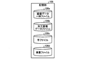
- FIG. 2 is a block diagram illustrating an example of the storage unit 106 of the overhead scanner device 100.
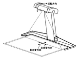
- FIG. 3 is a diagram illustrating an example of the appearance of an apparatus in which the linear imaging unit 110 and the area imaging unit 120 are integrated, and is a diagram illustrating a relationship among the main scanning direction, the sub-scanning direction, and the rotation direction by the motor 12.
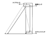
- FIG. 4 is a front view of the overhead scanner device 100 of the present embodiment.
- FIG. 5 is a side view of the overhead scanner device 100 of the present embodiment.
- FIG. 6 is a functional block diagram illustrating an example of the control unit 102 of the overhead scanner device 100.
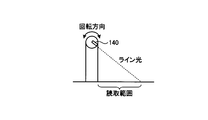
- FIG. 7 is a diagram schematically illustrating a method for acquiring a linear image by the image sensor 13 by controlling the linear imaging unit 110.
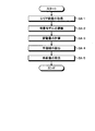
- FIG. 8 is a flowchart showing an example of basic processing in the overhead scanner device 100 of the present embodiment.
- FIG. 9 is a flowchart showing an example of a specific process in the overhead scanner device 100 of the present embodiment.
- FIG. 10 is a flowchart showing a subroutine of background model update processing.
- FIG. 11 is a diagram illustrating a one-dimensional GMM as an example.
- FIG. 12 is a diagram illustrating a two-dimensional GMM as an example.
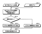
- FIG. 13 is a flowchart showing a subroutine of binary image generation processing from the variation amount.
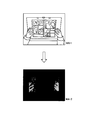
- FIG. 14 is a diagram illustrating an example of a frame image at the end and a hand region binary image.
- FIG. 15 is a flowchart showing a subroutine for noise removal processing.
- FIG. 16 is a diagram illustrating an example of image transition from the frame image at the end to the hand region binary image after noise removal.
- FIG. 17 is a flowchart showing a subroutine of medium area extraction processing.
- FIG. 18 is a diagram schematically illustrating processing for extracting the outline of a medium region from a linear image.
- FIG. 19 is a flowchart illustrating a subroutine of intersection pair detection processing.
- FIG. 20 is a diagram schematically illustrating intersection pairs in the intersection pair detection process.
- FIG. 21 is a diagram illustrating a processed image of a medium without distortion from which the image of the hand region has been removed.
- the reading target may be described as a manuscript such as a magazine.
- the reading target is not limited to this.
- Newspaper, a medium bound with staples, a stack of single sheets, and the like are read. Also good.
- two types of sensors that is, a medium image sensor and an area sensor are provided will be described.
- the present invention is not limited to this, and an image may be acquired using one type of sensor.
- FIG. 1 is a hardware configuration diagram illustrating an example of the overhead scanner device 100.
- the overhead scanner device 100 includes at least a linear imaging unit 110, an area imaging unit 120, and a control unit 102.
- the storage unit 106, the input / output interface unit 108, and the light source 140 are included. Is further provided. Further, these units are communicably connected via an arbitrary communication path.
- the storage unit 106 stores various databases, tables, files, and the like.
- the storage unit 106 is a storage unit, and for example, a memory device such as a RAM / ROM, a fixed disk device such as a hard disk, a flexible disk, an optical disk, or the like can be used.
- the storage unit 106 stores computer programs for giving instructions to a CPU (Central Processing Unit) and performing various processes.
- FIG. 2 is a block diagram illustrating an example of the storage unit 106 of the overhead scanner device 100.
- the storage unit 106 includes a temporary image data file 106a, a processed image data file 106b, a hand file 106c, and a background file 106d, as shown.
- the temporary image data file 106a temporarily stores image data read by the linear imaging unit 110 or the area imaging unit 120.
- the processed image data file 106b stores image data processed or edited from the image data read by the linear imaging unit 110.
- the hand file 106c stores the color and shape of hands and fingers presented by the user.
- the hand file 106c may store the color (skin color) and shape of the user's hand or finger for each user.
- the background file 106d stores a background model generated by a background model update unit 102b described later.
- the input / output interface unit 108 connects the linear imaging unit 110, the area imaging unit 120, and the light source 140 to the control unit 102.
- the light source 140 an LED light source, a laser light source, or the like can be used, and light is emitted from the light source to the reading range.
- the linear imaging unit 110 scans an original placed upward from above using the image sensor 13 and reads an image of the original.
- the linear imaging part 110 is provided with the controller 11, the motor 12, the image sensor (line sensor) 13, and the A / D converter 14, as shown in FIG.
- the controller 11 controls the motor 12, the image sensor 13, and the A / D converter 14 in response to a command from the control unit 102 via the input / output interface unit 108.
- the image sensor 13 photoelectrically converts light reaching from the line in the main scanning direction of the document into an analog charge amount for each pixel on the line.
- the A / D converter 14 converts the analog charge amount output from the image sensor 13 into a digital signal, and outputs one-dimensional image data.
- FIG. 3 is a diagram illustrating an example of the appearance of an apparatus in which the linear imaging unit 110 and the area imaging unit 120 are integrated, and is a diagram illustrating a relationship among the main scanning direction, the sub-scanning direction, and the rotation direction by the motor 12. .
- the one-dimensional image data of the line in the main scanning direction shown in the figure is read by the image sensor 13.
- the image sensor 13 is rotated in the illustrated rotation direction by driving the motor 12, the reading line of the image sensor 13 is moved in the illustrated sub-scanning direction.
- the image data of the two-dimensional document is read by the linear imaging unit 110.
- the area imaging unit 120 scans a document placed upward from above using the area sensor 22 and reads an image of the document.
- the area imaging unit 120 includes a controller 21, an area sensor 22, and an A / D converter 23 as shown in FIG.
- the controller 21 controls the area sensor 22 and the A / D converter 23 in response to a command from the control unit 102 via the input / output interface unit 108.
- the area sensor 22 photoelectrically converts light reaching from the document plane (two-dimensional plane in the main scanning direction and the sub-scanning direction shown in FIG. 3) into an analog charge amount for each pixel.
- the A / D converter 23 converts the analog charge amount output from the area sensor 22 into a digital signal, and outputs two-dimensional image data.
- two-dimensional image data is output from the A / D converter 23.
- the image sensor 13 can read more pixels per line than the area sensor 22, so that the image read by the linear imaging unit 110 is more than the image read by the area imaging unit 120. Is high definition (high image quality).
- an image read by the area imaging unit 120 may be referred to as an “area image”
- an image read by the linear imaging unit 110 may be referred to as a “linear image”.
- FIG. 4 is a front view of the overhead scanner device 100 of the present embodiment
- FIG. 5 is a side view of the overhead scanner device 100 of the present embodiment. 4 and 5, the solid line represents the imaging range of the image sensor 13, and the broken line represents the imaging range of the area sensor 22.
- the linear image includes an image of the area of the medium placement surface, and the area image includes the image of the scan switch 10 and the background image in a wider range than the linear image.
- the motor 12 of the linear imaging unit 110 is driven, and acquisition of a linear image is started.
- the control unit 102 includes a CPU or the like that controls the overhead scanner device 100 in an integrated manner.
- the control unit 102 has an internal memory for storing a control program, a program defining various processing procedures, and necessary data, and performs information processing for executing various processes based on these programs.
- FIG. 6 is a functional block diagram illustrating an example of the control unit 102 of the overhead scanner device 100.
- control unit 102 is roughly divided as shown in the drawing, and an area image acquisition unit 102a, a background model update unit 102b, a background variation calculation unit 102c, a coordinate conversion unit 102d, and a medium image acquisition Unit 102e, medium region extraction unit 102f, hand region extraction unit 102g, hand image removal unit 102h, and processed image recording unit 102i.
- the area image acquisition unit 102a controls the area imaging unit 120 to continuously acquire a plurality of area images. For example, as described above, the area image acquisition unit 102a controls the controller 21 of the area imaging unit 120 to acquire image data photoelectrically converted by the area sensor 22 and analog-digital converted by the A / D converter 23. The process of storing in the temporary image data file (buffer) 106a is repeated. For example, the area image acquisition unit 102a provides an area image for learning a background model of a document by performing continuous shooting and acquiring a continuous image (moving image) with the area sensor 22.
- the background model update unit 102b updates the background model around the medium based on the area images continuously acquired by the area image acquisition unit 102a.
- the background model update unit 102b may perform machine learning on a set of data points having multidimensional feature amounts using a GMM (Gaussian mixture model).
- the background model update unit 102b may generate a background model using a known background learning method.
- the background model update unit 102b may stop updating the background model when a hand is detected around the medium.
- the background model update unit 102b may store the latest background model generated in the background file 106d and update it according to learning.
- the background fluctuation amount calculation unit 102c calculates the fluctuation amount from the background model. That is, the background variation calculation unit 102c obtains a variation that is a difference between the latest background model stored in the background file 106d and the area image acquired by the area image acquisition unit 102a.
- the coordinate conversion unit 102d converts the coordinate system of the area image acquired via the area imaging unit 120 to the coordinate system of the linear image acquired via the linear imaging unit 110.
- the medium image acquisition unit 102e acquires a medium image via the linear imaging unit 110.
- the medium image acquisition unit 102e controls the linear imaging unit 110 to start acquisition of a linear image by the image sensor 13. To do.
- the medium image acquisition unit 102e controls the controller 11 of the linear imaging unit 110 to rotationally drive the motor 12, photoelectrically convert it by the image sensor 13, and convert it from analog to digital by the A / D converter 14.
- By synthesizing the one-dimensional image data for each line two-dimensional image data (linear image image data) is generated and stored in the image data temporary file 106a.
- the medium image acquisition unit 102e drives the motor 12 to rotate the line light source 140 in the rotation direction, and the line light in the main scanning direction from the line light source 140 is limited to the reading range.
- the reading range may be notified to the user by moving in the sub-scanning direction.
- the medium area extraction unit 102f extracts a medium area from the linear image acquired by the medium image acquisition unit 102e.
- the medium area extraction unit 102f may detect the luminance change points from the upper part and the lower part of the linear image to detect the upper and lower outlines of the medium area. Then, the medium area extraction unit 102f may detect the left outline of the medium area by connecting the left end of the upper end outline of the image area and the left end of the lower outline. Similarly, the medium area extraction unit 102f may detect the right outline of the medium area by connecting the right edge of the upper edge outline of the image area and the right edge of the lower outline.
- the hand region extraction unit 102g extracts a hand region based on the variation amount calculated by the background variation amount calculation unit 102c.
- the hand region extraction unit 102g may remove noise that is not a hand region from the variation amount calculated by the background variation amount calculation unit 102c.
- the hand region extraction unit 102g may remove noise based on color information of a finger that presses the scan switch 10 that instructs the image sensor 13 of the linear imaging unit 110 to start reading.
- the color information is stored in the hand file 106c, and based on the stored color information, a color change amount that does not belong to the color may be removed as noise.
- the hand region extraction unit 102g may binarize the hand region based on the change amount.
- the hand region extraction unit 102g may generate a color model from the foreground image, save it in the hand file 106c, detect pixels that match the color model, and acquire a binary image of the hand region. Further, the hand region based on the coordinate system of the area image may be converted into the coordinate system of the linear image under the control of the coordinate conversion unit 102d.
- the hand image removing unit 102h removes the hand region image extracted by the hand region extracting unit 102g from the medium region image extracted by the medium region extracting unit 102f.
- the hand image removal unit 102h removes the image of the hand region mapped on the medium image by the coordinate conversion unit 102d.
- the hand image removal unit 102h may determine the hand region inside the medium region by detecting an intersection pair of the contour of the medium region and the contour of the hand region. Further, the hand image removing unit 102h may complement the image of the removed medium area inside the hand area so as to fill the image of the hand area based on the medium image around the image of the hand area.
- the processed image recording unit 102i stores the processed image processed as described above in the processed image data file 106b.
- the processed image recording unit 102i stores the image of the medium from which the image of the hand area has been removed by the hand image removing unit 102h in the processed image data file 106b.
- the processed image recording unit 102i may separately perform processing such as distortion correction.
- FIG. 8 is a flowchart showing an example of basic processing in the overhead scanner device 100 of the present embodiment.
- the area image acquisition unit 102a controls the area imaging unit 120 to continuously acquire a plurality of area images (step SA-1).
- the area image acquisition unit 102a controls the controller 21 of the area imaging unit 120 to acquire image data of an area image photoelectrically converted by the area sensor 22 and analog-digital converted by the A / D converter 23 to obtain image data.
- the temporary file 106a is continuously stored.
- the background model update unit 102b generates a background model around the medium based on the area image acquired by the area image acquisition unit 102a (step SA-2).
- the background model update unit 102b may perform machine learning on a set of data points having multidimensional feature values using a known background learning method such as GMM.
- the background model update unit 102b updates the background model according to the area image continuously updated by the area image acquisition unit 102a, and stops the background model update when a hand is detected around the medium. .
- the background model update unit 102b stores the updated latest background model in the background file 106d.
- the background variation calculation unit 102c calculates the variation from the latest background model stored in the background file 106d (step SA-3). That is, the background fluctuation amount calculation unit 102c obtains a fluctuation amount that is a difference between the background model immediately before detecting the hand around the medium in the area image and the area image including the hand region acquired by the area image acquisition unit 102a. .
- the hand region extraction unit 102g extracts a hand region based on the variation amount calculated by the background variation amount calculation unit 102c (step SA-4).
- the hand region extraction unit 102g includes noise when the variation amount calculated by the background variation amount calculation unit 102c is used as a hand region, a scan switch that instructs reading by the image sensor 13 of the linear imaging unit 110 is included. Noise may be removed based on finger color information when 10 is pressed.
- the hand region extraction unit 102g generates a color model from the foreground image and saves it in the hand file 106c, detects pixels that apply to the color model, acquires a binary image of the hand region, and obtains a coordinate conversion unit 102d.
- the binarized hand region based on the coordinate system of the area image may be converted into a linear image coordinate system by the control.
- the hand image removal unit 102h removes the hand region image extracted by the hand region extraction unit 102g from the medium region image extracted by the medium region extraction unit 102f (step SA-5). For example, the hand image removal unit 102h removes the image of the hand region mapped on the medium image by the coordinate conversion unit 102d. Note that the hand image removal unit 102h may determine the hand region inside the medium region by detecting an intersection pair of the contour of the medium region and the contour of the hand region. The hand image removal unit 102h may complement the image of the medium area inside the removed hand area based on the medium image around the image of the hand area. The processed image from which the image of the hand area has been removed is recorded in the processed image data file 106b under the control of the processed image recording unit 102i.
- the above is an example of basic processing in the overhead scanner device 100 of the present embodiment.
- FIG. 9 is a flowchart showing an example of a specific process in the overhead scanner device 100 of the present embodiment.
- the area image acquisition unit 102a of the overhead scanner device 100 controls the area imaging unit 120 to acquire an area image (frame image) of the current frame (step SB-1).
- the background model update unit 102b updates the background models on both sides of the shooting range of the area imaging unit 120 based on the area images continuously acquired by the area image acquisition unit 102a (step SB-2). That is, in this embodiment, since it is assumed that the left and right double-sided medium such as a magazine is photographed by pressing the left and right hands from both sides, in each of the left and right areas divided by the center line of the shooting range of the area image, Build a background model.
- the background model update unit 102b determines whether or not to end the scan for acquiring the area image and stop the update of the background model (step SB-3). For example, in order not to learn the hand region as the background, the background model update unit 102b may stop scanning and update the background model when a hand is detected around the medium.
- FIG. 10 is a flowchart showing a subroutine of background model update processing.
- the background model update unit 102b calculates the number of images exceeding the luminance threshold in one side (right side, left side) region of the shooting range in the acquired frame image (step SC-1).
- Step SC-2 When the number of images exceeds a predetermined threshold (Step SC-3, Yes), update the background model such as the GMM model of each pixel on both sides of the shooting range (Step SC-4). Cancel.
- Step SC-3 Yes
- Step SC-4 update the background model such as the GMM model of each pixel on both sides of the shooting range
- Cancel In this process, it is determined whether or not there is a hand on the left side or the right side. If there is a hand, the background model is not updated. The reason is that if the hand color is also a background model, the hand region cannot be correctly extracted based on the variation amount.
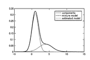
- FIG. 11 is a diagram illustrating a one-dimensional GMM as an example
- FIG. 12 is a diagram illustrating a two-dimensional GMM as an example.
- the GMM can construct a model by combining a plurality of Gaussian distributions.
- the model can be expressed by a combination of Gaussian distributions in multi-dimensions.
- the plurality of dimensions may be RGB primary colors, color / luminance expression parameters such as L * a * b *, and the like in the present embodiment.
- the background model update unit 102b determines to end the update scan of the area image and cancel the update of the background model (step SB-3, Yes)
- the frame image at the end is stored in the storage unit 106. Record (step SB-4).
- the background model update unit 102b may determine that the update of the background model is to be stopped when the scan switch 10 is pressed.
- the background model update unit 102b may store the finger color when the scan switch 10 is pressed in the hand file 106c.
- FIG. 13 is a flowchart showing a subroutine of binary image generation processing from the fluctuation amount.
- FIG. 14 is a diagram illustrating an example of a frame image at the end and a hand region binary image.
- the background variation calculation unit 102c performs RGB of each pixel based on the frame image (step SD-1, MA-1) at the end and the background model (step SD-2). By substituting the information into the background model, the fluctuation amount that is the difference from the background is calculated (step SD-3).
- step SD-4 when the variation amount for each pixel exceeds a predetermined threshold (step SD-4, Yes), the background variation amount calculation unit 102c sets the gradation value of the pixel to 255 (white) (step S4).
- step SD-5 If the threshold value is not exceeded (step SD-4, No), the gradation value of the pixel is set to 0 (black) (step SD-6), thereby allowing the hand region binary image (MA- 2) is generated (step SD-7).
- MA-2 the hand region binary image normally includes noise.
- the cause of the noise is that when the medium is pressed by hand, the medium tends to extend to both sides, and the medium moves slightly. Therefore, a noise removal process described later is performed.
- FIG. 15 is a flowchart showing a subroutine of noise removal processing.
- FIG. 16 is a diagram illustrating an example of image transition from the frame image at the end to the hand region binary image after noise removal.
- the hand region extraction unit 102g generates a color model from the finger color (MB-3) recorded in the hand file 106c when the scan switch 10 is pressed (step SE- 3).
- the hand region extraction unit 102g the frame image at the end (step SE-1, MB-1), the hand region binary image including noise (step SE-2, MB-2), and the color model (step Based on SE-3, MB-3), the RGB information of the pixel whose gradation value is 255 (white) in the binary image is substituted into the color model (step SE-4).
- step SE-5 when the degree of coincidence with the color model is equal to or smaller than the predetermined threshold (step SE-5, Yes), the hand region extraction unit 102g sets the gradation value of the pixel to 0 (black) (step SE-6). ), When the threshold value is exceeded (step SE-5, No), by maintaining the gradation value of the pixel at 255 (white) (step SE-7), the hand region binary image (from which noise is removed) ( MB-4) is generated.
- the hand region extraction unit 102g records the hand region binary image from which noise has been removed in the hand file 106c (step SB-8).
- the overhead scanner 100 returns the processing to SB-1 again, and repeats the above-described processing to perform background model update processing and hand region binary image acquisition processing.
- the above is an example of processing performed in the coordinate system of the area image. Next, an example of processing performed in the linear image coordinate system will be described.
- the medium image acquisition unit 102e controls the linear imaging unit 110 to acquire a linear image by the image sensor 13 (step SB-9).
- the medium image acquisition unit 102e controls the controller 11 of the linear imaging unit 110 to rotate and drive the motor 12, and performs primary conversion for each line photoelectrically converted by the image sensor 13 and analog-digital converted by the A / D converter 14.
- two-dimensional image data (linear image image data) is generated and stored in the temporary image data file 106a.
- FIG. 17 is a flowchart showing a subroutine of medium area extraction processing.
- FIG. 18 is a diagram schematically illustrating processing for extracting the outline of the medium region from the linear image.
- the medium region extraction unit 102f searches from the upper and lower parts of the linear image (SF-1) of the medium, respectively, and detects the luminance change point (step SF-2, SF-1). MC-1).
- the medium area extraction unit 102f scans from the middle of the luminance change point toward both ends in each of the upper part and the lower part (step SF-3).
- the medium area extracting unit 102f detects, as the end points of the upper and lower contours, where the coordinate (height) of the luminance change point changes suddenly in each of the upper part and the lower part (Step SF-4). That is, only detecting the luminance change point from the upper part and the lower part also detects the hand area outside the medium area, so that both ends of the outline of the medium area are determined in this process.
- the medium area extraction unit 102f connects the luminance change points to the end points at both ends in the upper and lower parts, and generates the upper and lower contours of the image area (steps SF-5 and MC-2).
- the medium area extraction unit 102f generates a left outline of the medium area by connecting the upper left and lower left end points, and generates a right outline of the medium area by connecting the upper and lower right end points. (Step SF-6, MC-3). Thus, the medium area can be extracted.
- the hand area extracting unit 102g when an image of the medium area is extracted by the cropping process or the like by the medium area extracting unit 102f (step SB-10), the hand area extracting unit 102g generates noise in order to extract the hand area.
- the removed hand region binary image is acquired from the hand file 106c (step SB-11).
- the hand region extraction unit 102g converts the hand region binary image based on the coordinate system of the area image into the linear image coordinate system under the control of the coordinate conversion unit 102d (step SB-12).
- the hand region extraction unit 102g maps the hand region binary image converted into the linear image coordinate system in step SB-12 onto the medium image acquired in step SB-10, so that the hand region is the contour of the hand region.
- An outline is extracted (step SB-13).
- the hand image removal unit 102h detects a pair of intersections of the medium outline and the hand outline, which is the outline of the medium area, in order to remove the image of the hand area from the image of the medium area (step SB-14).
- FIG. 19 is a flowchart showing a subroutine of intersection pair detection processing.
- FIG. 20 is a diagram schematically illustrating intersection pairs in the intersection pair detection process.
- the hand image removal unit 102h scans the sub-line segment of each contour of the hand contour to detect the intersection with the left (right) contour of the medium (step SH-1). .
- the hand image removing unit 102h checks whether the hand contour between the intersection pairs is inside or outside in order from the top (step SH-2).
- the hand image removing unit 102h records the intersection pair in the storage unit 106 (step SH-4). Similarly, for the medium right contour, the hand image removal unit 102h records the intersection pair in the storage unit 106 when the hand contour is on the left side of the medium right contour of the intersection pair (step SH-3, Yes). (Step SH-4).
- the hand image removal unit 102h records the intersection pair, and when there is an unchecked intersection pair (step SH-4) or when there is no hand outline on the right side (left side) of the medium left (right) outline of the intersection pair (Step SH-3, No), the process is returned to step SH-2, and the next intersection pair is checked. Thereby, the outer outline of the hand area in the medium area can be specified by the intersection point pair.
- the hand image removing unit 102h paints the image of the hand area in the medium area surrounded by the line connecting the recorded intersection pairs and the original hand area (step SB-15).
- the hand image removal unit 102h may determine a color for filling the image of the hand area based on the color information of the medium image around the image of the hand area in the medium area.
- FIG. 21 is a diagram showing a processed image of the medium that has been processed by the above processing and from which the image of the hand region has been removed and has no distortion. As shown in FIG. 21, the distortion due to the bending of the medium is corrected by the distortion correction process.
- the processed image recording unit 102i stores the processed image data in the processed image data file 106b (step SB-17), and ends the process.
- the above is an example of the specific processing in the overhead scanner device 100 of the present embodiment.
- the flow of one process when an image of two pages of left and right spread pages is read has been described.
- the present invention can be applied to other types of media such as a medium of two pages of upper and lower pages. Is also good.
- the overhead scanner device 100 continuously acquires a plurality of images, updates the background model around the medium based on the continuously acquired images, and changes from the background model. The amount is calculated, the hand region is extracted based on the variation amount, and the image of the hand region is removed from the image of the medium. As a result, the hand region is always detected in the background model that is updated by learning without detecting the hand region with a specific color. Even when the color of a book as a background is similar, it is possible to prevent erroneous detection and remove an image of a hand region with high accuracy.
- a background model is constructed from the area image acquired and updated via the area sensor 22, and the coordinate system of the area image acquired via the area sensor 22 is used via the image sensor 13. Then, the image is converted into the coordinate system of the linear image acquired in this way, and the image of the hand area mapped on the medium image is removed.
- the image is converted into the coordinate system of the linear image acquired in this way, and the image of the hand area mapped on the medium image is removed.
- the noise when extracting the hand region based on the amount of variation from the background model is removed based on the color information of the finger that has pressed the scan switch 10 by the image sensor 13. Even if there is a slight movement of the medium that stretches the medium when the medium is pressed, noise can be appropriately removed.
- the update of the background model is stopped, so that it is possible to appropriately prevent learning of the hand region as the background.
- a color model is generated from the foreground image, pixels that apply to the color model are detected, and a binary image of the hand region is acquired. Therefore, the hand region in the linear image including the medium region is obtained. It can be detected properly.
- the outline of the medium area is acquired based on the luminance change point detected by scanning from above and below the medium image, the outline of the medium area can be appropriately acquired.
- the present invention may be implemented in various different embodiments other than the above-described embodiments within the scope of the technical idea described in the claims.
- the area sensor 22 may detect light in a wavelength region other than the infrared region.
- the overhead scanner device 100 performs processing in a stand-alone form
- processing is performed in response to a request from a client terminal in a separate housing from the overhead scanner device 100, and the processing result is You may make it return to a client terminal.
- all or a part of the processes described as being automatically performed can be manually performed, or all of the processes described as being manually performed can be performed. Alternatively, a part can be automatically performed by a known method.
- the processing procedures, control procedures, specific names, information including registration data for each processing, screen examples, and database configuration shown in the above documents and drawings may be arbitrarily changed unless otherwise specified. Can do.
- each illustrated component is functionally conceptual and does not necessarily need to be physically configured as illustrated.
- the processing functions provided in each apparatus of the overhead scanner apparatus 100 are interpreted or executed by a CPU (Central Processing Unit) and the CPU. It may be realized by a program to be executed, or may be realized as hardware by wired logic.
- the program is recorded on a recording medium to be described later, and is mechanically read by the overhead scanner device 100 as necessary. That is, a computer program for performing various processes is recorded in the storage unit 106 such as a ROM or an HDD. This computer program is executed by being loaded into the RAM, and constitutes a control unit in cooperation with the CPU.
- the computer program may be stored in an application program server connected to the overhead scanner device 100 via an arbitrary network, and may be downloaded in whole or in part as necessary. is there.
- the program according to the present invention may be stored in a computer-readable recording medium, or may be configured as a program product.
- the “recording medium” includes a memory card, USB memory, SD card, flexible disk, magneto-optical disk, ROM, EPROM, EEPROM, CD-ROM, MO, DVD, and Blu-ray (registered trademark). It includes any “portable physical medium” such as Disc.
- the “program” is a data processing method described in an arbitrary language or description method, and may be in any format such as source code or binary code. Note that the “program” is not necessarily limited to a single configuration, but is distributed in the form of a plurality of modules and libraries, or in cooperation with a separate program typified by an OS (Operating System). Including those that achieve the function.
- OS Operating System
- a well-known structure and procedure can be used about the specific structure for reading a recording medium in each apparatus shown in embodiment, a reading procedure, or the installation procedure after reading.
- Various databases and the like (image data temporary file 106a, processed image data file 106b, hand file 106c, and background file 106d) stored in the storage unit 106 are a memory device such as a RAM and a ROM, a fixed disk device such as a hard disk, It is a storage means such as a flexible disk and an optical disk, and stores various programs, tables, databases, etc. used for various processes.
- the overhead scanner device 100 may be configured as an information processing device such as a known personal computer or workstation, or may be configured by connecting an arbitrary peripheral device to the information processing device. Further, the overhead scanner device 100 may be realized by installing software (including a program, data, and the like) that realizes the method of the present invention in the information processing device. Furthermore, the specific form of distribution / integration of the devices is not limited to that shown in the figure, and all or a part of them may be functional or physical in arbitrary units according to various additions or according to functional loads. Can be distributed and integrated. That is, the above-described embodiments may be arbitrarily combined and may be selectively implemented.
- the overhead scanner device, the image acquisition method, and the program according to the present invention can be implemented in many industrial fields, particularly in the image processing field that handles images read by a scanner, and are extremely useful. is there.
Landscapes
- Engineering & Computer Science (AREA)
- Multimedia (AREA)
- Theoretical Computer Science (AREA)
- General Physics & Mathematics (AREA)
- Physics & Mathematics (AREA)
- Human Computer Interaction (AREA)
- Psychiatry (AREA)
- Social Psychology (AREA)
- General Health & Medical Sciences (AREA)
- Computer Vision & Pattern Recognition (AREA)
- Health & Medical Sciences (AREA)
- Signal Processing (AREA)
- Image Input (AREA)
- Facsimile Scanning Arrangements (AREA)
- Editing Of Facsimile Originals (AREA)
- Studio Devices (AREA)
Abstract
本実施形態によれば、オーバヘッドスキャナ装置において、画像を連続して取得し、連続的に取得される画像に基づいて、媒体周辺の背景モデルを更新し、背景モデルからの変動量を計算し、変動量に基づいて、手領域を抽出し、媒体の画像から手領域の画像を除去する。
Description
本発明は、オーバヘッドスキャナ装置、画像取得方法、および、プログラムに関する。
従来、操作性を向上させるオーバヘッドスキャナが開発されている。
ここで、自動撮影モードにおいて、ユーザが本を押さえる手指の位置や動きを認識して、抽出した肌色領域を2値化して手指の輪郭を算出し、算出した輪郭について所定の形状パターンとの比較により形状認識して、指の本数と各指先の座標とを推定する(特許文献1を参照)。
また、撮影画像には、書籍および背景となる載置面の像のほか、書籍の周縁部を押さえる左右の手指の像が含まれるため、肌色領域を白黒画像に変換し、外接矩形が撮影画像の外側に接する場合に、外接矩形を手領域として設定する(特許文献2を参照)。
しかしながら、従来のオーバヘッドスキャナにおいては、肌色で手指の輪郭を検出しているために、利用者が手袋をはめて操作している場合や、指色と背景となる本の色が似ている場合などにおいて、手領域の検出精度が低いという問題点を有していた。
本発明は、上記問題点に鑑みてなされたもので、精度よく手領域の画像を除去することができる、オーバヘッドスキャナ装置、画像取得方法、および、プログラムを提供することを目的とする。
このような目的を達成するため、本発明に係るオーバヘッドスキャナ装置は、複数の画像を連続して取得する画像取得手段と、上記画像取得手段により連続的に取得される上記画像に基づいて、媒体周辺の背景モデルを更新する背景モデル更新手段と、上記背景モデルからの変動量を計算する背景変動量計算手段と、上記変動量に基づいて、手領域を抽出する手領域抽出手段と、上記媒体の画像から手領域の画像を除去する手画像除去手段と、を備える。
また、本発明に係る画像取得方法は、オーバヘッドスキャナ装置の制御部で実行される、複数の画像を連続して取得する画像取得ステップと、上記画像取得ステップにて連続的に取得される上記画像に基づいて、媒体周辺の背景モデルを更新する背景モデル更新ステップと、上記背景モデルからの変動量を計算する背景変動量計算ステップと、上記変動量に基づいて、手領域を抽出する手領域抽出ステップと、上記媒体の画像から手領域の画像を除去する手画像除去ステップと、を含む。
また、本発明に係るプログラムは、複数の画像を連続して取得する画像取得ステップと、上記画像取得ステップにて連続的に取得される上記画像に基づいて、媒体周辺の背景モデルを更新する背景モデル更新ステップと、上記背景モデルからの変動量を計算する背景変動量計算ステップと、上記変動量に基づいて、手領域を抽出する手領域抽出ステップと、上記媒体の画像から手領域の画像を除去する手画像除去ステップと、をオーバヘッドスキャナ装置の制御部に実行させる。
また、本発明に係るコンピュータ読み取り可能な記録媒体は、前記に記載の本発明に係るプログラムを記録する。
この発明によれば、精度よく手領域の画像を除去することができる。
以下に、本発明に係るオーバヘッドスキャナ装置、画像取得方法、および、プログラムの実施形態を図面に基づいて詳細に説明する。なお、この実施形態により本発明が限定されるものではない。特に、本実施形態においては、読み取り対象を雑誌などの原稿として説明することがあるが、これに限られず、新聞紙や、ステープルで綴じられた媒体や、単票を重ねた束等を読み取り対象としてもよい。また、本実施形態においては、媒体画像センサとエリアセンサの2種類のセンサを備えた例について説明するが、本発明はこれに限られず1種類のセンサを用いて画像を取得してもよい。
[1.本実施形態の構成]
本実施形態に係るオーバヘッドスキャナ装置100の構成について図1を参照して説明する。図1は、オーバヘッドスキャナ装置100の一例を示すハードウェア構成図である。
本実施形態に係るオーバヘッドスキャナ装置100の構成について図1を参照して説明する。図1は、オーバヘッドスキャナ装置100の一例を示すハードウェア構成図である。
図1に示すように、オーバヘッドスキャナ装置100は、リニア撮像部110と、エリア撮像部120と、制御部102とを少なくとも備え、本実施形態において、記憶部106と入出力インターフェース部108と光源140を更に備える。また、これら各部は任意の通信路を介して通信可能に接続されている。
記憶部106は、各種のデータベースやテーブルやファイルなどを格納する。記憶部106は、ストレージ手段であり、例えばRAM・ROM等のメモリ装置や、ハードディスクのような固定ディスク装置、フレキシブルディスク、光ディスク等を用いることができる。記憶部106には、CPU(Central Processing Unit)に命令を与え各種処理を行うためのコンピュータプログラムが記録されている。ここで、図2は、オーバヘッドスキャナ装置100の記憶部106の一例を示すブロック図である。
図2に示すように、記憶部106は、図示の如く、画像データ一時ファイル106a、加工画像データファイル106b、手ファイル106c、および、背景ファイル106dを備える。
このうち、画像データ一時ファイル106aは、リニア撮像部110またはエリア撮像部120で読み取られた画像データを一時的に記憶する。
また、加工画像データファイル106bは、リニア撮像部110で読み取られた画像データから、加工または編集された画像データを記憶する。
また、手ファイル106cは、利用者により提示される手や指等の色や形等を記憶する。ここで、手ファイル106cは、利用者ごとに、利用者の手や指の色(肌色)や形等を記憶してもよい。
また、背景ファイル106dは、後述する背景モデル更新部102bにより生成される背景モデルを記憶する。
入出力インターフェース部108は、リニア撮像部110やエリア撮像部120、光源140を、制御部102と接続する。光源140は、LED光源やレーザー光源等を用いることができ、当該光源から読み取り範囲に光を射出する。
また、リニア撮像部110は、上向きに設置された原稿を、画像センサ13を用いて上方よりスキャンして原稿の画像を読み取る。ここで、本実施形態において、リニア撮像部110は、図1に示すように、コントローラ11と、モータ12と、画像センサ(ラインセンサ)13と、A/Dコンバータ14とを備える。コントローラ11は、入出力インターフェース部108を介した制御部102からの指令に応じて、モータ12、画像センサ13、および、A/Dコンバータ14を制御する。画像センサ13は、原稿の主走査方向のラインから届く光を、ライン上の画素ごとにアナログ電荷量に光電変換する。そして、A/Dコンバータ14は、画像センサ13から出力されたアナログ電荷量をデジタル信号に変換し、一次元の画像データを出力する。モータ12が回転駆動すると、画像センサ13の読み取り対象の原稿ラインが副走査方向に移動する。これにより、ラインごとに一次元の画像データがA/Dコンバータ14から出力され、制御部102は、これらを合成することにより二次元の画像データを生成する。ここで、図3は、リニア撮像部110とエリア撮像部120を一体化させた装置の外観の一例を示し、主走査方向と副走査方向とモータ12による回転方向との関係を示す図である。
図3に示すように、原稿を上向きに設置して、上方よりリニア撮像部110にて原稿を撮像する場合、図示の主走査方向のラインの一次元画像データが、画像センサ13により読み取られる。そして、モータ12の駆動により画像センサ13が図示の回転方向に回転すると、それに伴って、画像センサ13の読み取りラインは、図示の副走査方向に移動する。これにより、二次元の原稿の画像データが、リニア撮像部110によって読み取られることとなる。
再び図1に戻り、エリア撮像部120は、上向きに設置された原稿を、エリアセンサ22を用いて上方よりスキャンして原稿の画像を読み取る。ここで、本実施形態において、エリア撮像部120は、図1に示すように、コントローラ21と、エリアセンサ22と、A/Dコンバータ23とを備える。コントローラ21は、入出力インターフェース部108を介した制御部102からの指令に応じて、エリアセンサ22、および、A/Dコンバータ23を制御する。エリアセンサ22は、原稿平面(図3に図示した主走査方向と副走査方向の2次元平面)から届く光を、画素ごとにアナログ電荷量に光電変換する。そして、A/Dコンバータ23は、エリアセンサ22から出力されたアナログ電荷量をデジタル信号に変換し、二次元の画像データを出力する。これにより、二次元の画像データがA/Dコンバータ23から出力される。なお、本実施形態において、エリアセンサ22に比べて、画像センサ13は、1ラインの画素数を多く読み取れるので、エリア撮像部120により読み取られる画像よりも、リニア撮像部110により読み取られる画像の方が高精細(高画質)である。なお、以下、両者を区別するために、エリア撮像部120により読み取られる画像を「エリア画像」と呼び、リニア撮像部110により読み取られる画像を「リニア画像」と呼ぶ場合がある。
ここで、図4は、本実施の形態のオーバヘッドスキャナ装置100の正面図であり、図5は、本実施の形態のオーバヘッドスキャナ装置100の側面図である。図4および図5において、実線は、画像センサ13の撮像範囲を表しており、破線は、エリアセンサ22の撮像範囲を表している。本実施形態では、図示のように、リニア画像は、媒体の載置面の領域の画像を含み、エリア画像は、リニア画像よりも広範囲に、スキャンスイッチ10の画像や背景画像を含んでいる。なお、本実施の形態において、スキャンスイッチ10が押下されることにより、リニア撮像部110のモータ12が駆動し、リニア画像の取得が開始される。
制御部102は、オーバヘッドスキャナ装置100を統括的に制御するCPU等からなる。制御部102は、制御プログラムと各種の処理手順等を規定したプログラムと所要データとを格納するための内部メモリを有し、これらプログラムに基づいて種々の処理を実行するための情報処理を行う。ここで、図6は、オーバヘッドスキャナ装置100の制御部102の一例を示す機能ブロック図である。
図6に示すように、制御部102は、図示の如く、大別して、エリア画像取得部102aと、背景モデル更新部102bと、背景変動量計算部102cと、座標変換部102dと、媒体画像取得部102eと、媒体領域抽出部102fと、手領域抽出部102gと、手画像除去部102hと、加工画像記録部102iとを備える。
エリア画像取得部102aは、エリア撮像部120を制御して、複数のエリア画像を連続して取得する。例えば、エリア画像取得部102aは、上述のように、エリア撮像部120のコントローラ21を制御して、エリアセンサ22により光電変換されA/Dコンバータ23によりアナログデジタル変換された画像データを取得して画像データ一時ファイル(バッファ)106aに格納する処理を繰り返す。例えば、エリア画像取得部102aは、エリアセンサ22で、連続撮影を行って連続画像(動画像)を取得することにより、原稿の背景モデルを学習するためのエリア画像を提供する。
背景モデル更新部102bは、エリア画像取得部102aにより連続的に取得されるエリア画像に基づいて、媒体周辺の背景モデルを更新する。例えば、背景モデル更新部102bは、GMM(Gaussian mixture model:混合ガウスモデル)を用いて、多次元の特徴量を持つデータ点の集合を機械学習してもよい。そのほか、背景モデル更新部102bは、公知の背景学習手法を用い背景モデルを生成してもよい。ここで、手領域をも背景として学習しないようにするため、背景モデル更新部102bは、媒体周辺に手を検出した場合に、背景モデルの更新を中止してもよい。なお、本実施形態において、背景モデル更新部102bは、生成した最新の背景モデルを背景ファイル106dに保存しておき、学習に応じて更新してもよい。
背景変動量計算部102cは、背景モデルからの変動量を計算する。すなわち、背景変動量計算部102cは、背景ファイル106dに保存された最新の背景モデルと、エリア画像取得部102aにより取得されたエリア画像との差分である変動量を求める。
座標変換部102dは、エリア撮像部120を介して取得されるエリア画像の座標系から、リニア撮像部110を介して取得されるリニア画像の座標系に変換する。
媒体画像取得部102eは、リニア撮像部110を介して媒体画像を取得する。本実施形態において、利用者によりスキャンスイッチ10が押下されると、図7に示すように、媒体画像取得部102eは、リニア撮像部110を制御して、画像センサ13によるリニア画像の取得を開始する。例えば、媒体画像取得部102eは、上述のように、リニア撮像部110のコントローラ11を制御して、モータ12を回転駆動させ、画像センサ13により光電変換されA/Dコンバータ14によりアナログデジタル変換されたラインごとの一次元画像データを合成することにより、二次元の画像データ(リニア画像の画像データ)を生成し、画像データ一時ファイル106aに格納する。ここで、リニア撮像部110を側面から見た状態を表し、ライン光源140からの光照射の一例を示す図である。図7に示すように、媒体画像取得部102eは、モータ12を駆動させることにより、ライン光源140を回転方向に回転させ、ライン光源140からの主走査方向のライン光を、読み取り範囲を限度として副走査方向に移動させることで、利用者に読み取り範囲を通知してもよい。
媒体領域抽出部102fは、媒体画像取得部102eにより取得されたリニア画像から媒体領域を抽出する。例えば、媒体領域抽出部102fは、リニア画像の上部と下部から、それぞれ輝度の変化点を検出して、媒体領域の上部輪郭と下部輪郭を検出してもよい。そして、媒体領域抽出部102fは、画像領域の上端輪郭の左端と、下部輪郭の左端を結ぶことにより、媒体領域の左輪郭を検出してもよい。同様に、媒体領域抽出部102fは、画像領域の上端輪郭の右端と、下部輪郭の右端を結ぶことにより、媒体領域の右輪郭を検出してもよい。
手領域抽出部102gは、背景変動量計算部102cにより計算された変動量に基づいて、手領域を抽出する。ここで、手領域抽出部102gは、背景変動量計算部102cにより計算された変動量から、手領域ではないノイズを除去してもよい。例えば、手領域抽出部102gは、リニア撮像部110の画像センサ13による読取開始を指示するスキャンスイッチ10を押下した指の色情報に基づいて、ノイズを除去してもよい。例えば、色情報は、手ファイル106cに保存されており、保存された色情報に基づいて、その色に属しない色の変化量をノイズとして除去してもよい。なお、手領域抽出部102gは、変化量に基づく手領域を2値化してもよい。例えば、手領域抽出部102gは、前景画像から色モデルを生成して手ファイル106cに保存し、色モデルに当てはまるピクセルを検出して、手領域の2値画像を取得してもよい。また、座標変換部102dの制御により、エリア画像の座標系に基づく手領域を、リニア画像の座標系に変換させてもよい。
手画像除去部102hは、媒体領域抽出部102fにより抽出された媒体領域の画像から、手領域抽出部102gにより抽出された手領域の画像を除去する。本実施形態において、リニア画像とエリア画像の座標系が異なるので、手画像除去部102hは、座標変換部102dにより媒体画像上にマッピングされた手領域の画像を除去する。なお、手画像除去部102hは、媒体領域の輪郭と手領域の輪郭との交点ペアを検出することにより、媒体領域内側の手領域を判定してもよい。また、手画像除去部102hは、手領域の画像周辺の媒体画像に基づいて、手領域の画像を塗りつぶすように、除去した手領域内側の媒体領域の画像を補完してもよい。
加工画像記録部102iは、上述のように処理を受けた加工画像を加工画像データファイル106bに格納する。例えば、本実施の形態において、加工画像記録部102iは、手画像除去部102hにより手領域の画像が除去された媒体の画像を加工画像データファイル106bに格納する。加工画像記録部102iは、歪み補正等の加工処理を別途行ってもよい。
[2.本実施形態の処理]
上述した構成のオーバヘッドスキャナ装置100で実行される処理の一例について、図8~図21を参照して説明する。
上述した構成のオーバヘッドスキャナ装置100で実行される処理の一例について、図8~図21を参照して説明する。
[2-1.基本処理]
本実施形態のオーバヘッドスキャナ装置100における基本処理の一例について図8を参照して説明する。図8は、本実施形態のオーバヘッドスキャナ装置100における基本処理の一例を示すフローチャートである。
本実施形態のオーバヘッドスキャナ装置100における基本処理の一例について図8を参照して説明する。図8は、本実施形態のオーバヘッドスキャナ装置100における基本処理の一例を示すフローチャートである。
図8に示すように、まず、エリア画像取得部102aは、エリア撮像部120を制御して、複数のエリア画像を連続して取得する(ステップSA-1)。例えば、エリア画像取得部102aは、エリア撮像部120のコントローラ21を制御して、エリアセンサ22により光電変換されA/Dコンバータ23によりアナログデジタル変換されたエリア画像の画像データを取得して画像データ一時ファイル106aに格納することを連続的に行う。
そして、背景モデル更新部102bは、エリア画像取得部102aにより取得されたエリア画像に基づいて、媒体周辺の背景モデルを生成する(ステップSA-2)。例えば、背景モデル更新部102bは、GMM等の公知の背景学習手法を用いて、多次元の特徴量を持つデータ点の集合を機械学習してもよい。なお、背景モデル更新部102bは、エリア画像取得部102aにより連続的に更新されるエリア画像に応じて背景モデルを更新する一方、媒体周辺に手を検出した場合に、背景モデルの更新を中止する。なお、背景モデル更新部102bは、更新した最新の背景モデルを背景ファイル106dに保存する。
そして、背景変動量計算部102cは、背景ファイル106dに記憶された最新の背景モデルからの変動量を計算する(ステップSA-3)。すなわち、背景変動量計算部102cは、エリア画像において媒体周辺に手を検出する直前の背景モデルと、エリア画像取得部102aにより取得された手領域を含むエリア画像との差分である変動量を求める。
そして、手領域抽出部102gは、背景変動量計算部102cにより計算された変動量に基づいて、手領域を抽出する(ステップSA-4)。ここで、手領域抽出部102gは、背景変動量計算部102cにより計算された変動量そのものを手領域にするとノイズが含まれるため、リニア撮像部110の画像センサ13による読取開始を指示するスキャンスイッチ10を押下した際の指の色情報に基づいて、ノイズを除去してもよい。なお、手領域抽出部102gは、前景画像から色モデルを生成して手ファイル106cに保存し、色モデルに当てはまるピクセルを検出して、手領域の2値画像を取得し、座標変換部102dの制御により、エリア画像の座標系に基づく2値化した手領域を、リニア画像の座標系に変換させてもよい。
そして、手画像除去部102hは、媒体領域抽出部102fにより抽出された媒体領域の画像から、手領域抽出部102gにより抽出された手領域の画像を除去する(ステップSA-5)。例えば、手画像除去部102hは、座標変換部102dにより媒体画像上にマッピングされた手領域の画像を除去する。なお、手画像除去部102hは、媒体領域の輪郭と手領域の輪郭との交点ペアを検出することにより、媒体領域内側の手領域を判定してもよい。また、手画像除去部102hは、手領域の画像周辺の媒体画像に基づいて、除去した手領域内側の媒体領域の画像を補完してもよい。なお、手領域の画像が除去された加工画像は、加工画像記録部102iの制御により、加工画像データファイル106bに記録される。
以上が、本実施形態のオーバヘッドスキャナ装置100における基本処理の一例である。
[2-2.具体化処理]
つづいて、上述した基本処理において、更に、媒体領域抽出処理や交点ペア抽出処理等を更に含む具体化処理の一例について図9~図21を参照して説明する。図9は、本実施形態のオーバヘッドスキャナ装置100における具体化処理の一例を示すフローチャートである。
つづいて、上述した基本処理において、更に、媒体領域抽出処理や交点ペア抽出処理等を更に含む具体化処理の一例について図9~図21を参照して説明する。図9は、本実施形態のオーバヘッドスキャナ装置100における具体化処理の一例を示すフローチャートである。
図9に示すように、まず、オーバヘッドスキャナ装置100のエリア画像取得部102aは、エリア撮像部120を制御して、現在フレームのエリア画像(フレーム画像)を取得する(ステップSB-1)。
そして、背景モデル更新部102bは、エリア画像取得部102aにより連続的に取得されるエリア画像に基づいて、エリア撮像部120の撮影範囲両側の背景モデルを更新する(ステップSB-2)。すなわち、本具体化処理では、雑誌等の左右見開きの媒体を両側から左右の手で押さえて撮影することを前提としているため、エリア画像の撮影範囲の中心線で分断した左右の領域それぞれにおいて、背景モデルを構築する。
そして、背景モデル更新部102bは、エリア画像の取得のためのスキャンを終了して背景モデルの更新を中止するか否かを判定する(ステップSB―3)。例えば、手領域をも背景として学習しないようにするため、背景モデル更新部102bは、媒体周辺に手を検出した場合に、スキャンを終了して背景モデルの更新を中止してもよい。ここで、図10は、背景モデル更新処理のサブルーチンを示すフローチャートである。
図10に示すように、背景モデル更新部102bは、取得されたフレーム画像(ステップSC-1)に、撮影範囲の片側(右側、左側)領域内に、輝度閾値を超える画像の数を計算し(ステップSC-2)、画像の数が所定の閾値を超えた場合に(ステップSC-3,Yes)、撮影範囲両側の各ピクセルのGMMモデル等の背景モデルの更新(ステップSC-4)を中止する。この処理では、左側あるいは右側に手があるかどうかを判断しており、手がある場合は背景モデルを更新しない。その理由は、手の色も背景モデルになると、変動量に基づいて手領域を正しく抽出できなくなるためである。
ここで、GMM(Gaussian mixture model:混合ガウスモデル)は、多次元の特徴量をもつデータ点の集合を機械学習により分類するための重要な手法である。ここで、図11は、1次元のGMMを一例として示す図であり、図12は、2次元のGMMを一例として示す図である。図11に示すように、GMMは、複数のガウス分布の組み合わせによりモデルを構築することができる。そして、1次元の広がりのみならず、図12に示すように、多次元においてもガウス分布の組み合わせでモデルを表現することができる。ここで、複数の次元は、本実施形態において、RGBの三原色や、L*a*b*等の色・輝度表現パラメータ等であってもよい。
再び図9に戻り、背景モデル更新部102bは、エリア画像の更新スキャンを終了して背景モデルの更新を中止すると判定すると(ステップSB-3,Yes)、終了時のフレーム画像を記憶部106に記録する(ステップSB-4)。ここで、背景モデル更新部102bは、スキャンスイッチ10が押下された場合に、背景モデルの更新を中止すると判定してもよい。その際、背景モデル更新部102bは、スキャンスイッチ10を押した時の指色を手ファイル106cに保存してもよい。
そして、背景変動量計算部102cは、両側のGMMモデルからの終了時のフレーム画像の変動量を求め(ステップSB-5)、手領域の2値画像を生成する(ステップSB-6)。ここで、図13は、変動量からの2値画像生成処理のサブルーチンを示すフローチャートである。また、図14は、終了時のフレーム画像と、手領域2値画像の一例を示す図である。
図13および図14に示すように、背景変動量計算部102cは、終了時のフレーム画像(ステップSD-1,MA-1)と背景モデル(ステップSD-2)に基づいて、各ピクセルのRGB情報を背景モデルに代入することにより、背景との差分であるところの変動量を算出する(ステップSD-3)。
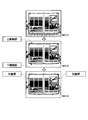
そして、背景変動量計算部102cは、各ピクセルについての変動量が所定の閾値を超えている場合(ステップSD-4,Yes)、そのピクセルの階調値を255(白)に設定し(ステップSD-5)、閾値を超えない場合(ステップSD-4,No)、そのピクセルの階調値を0(黒)に設定することにより(ステップSD-6)、手領域2値画像(MA-2)を生成する(ステップSD-7)。なお、図14のMA-2に示すように、通常、手領域2値画像には、ノイズが含まれている。ノイズの原因は、手で媒体を押さえるときに媒体を両側に伸ばす傾向にあり、媒体が微動するためである。そのため、後述のノイズ除去処理を行う。
再び図9に戻り、手領域抽出部102gは、背景変動量計算部102cにより計算された変動量から、手領域ではないノイズを除去する(ステップSB-7)。ここで、図15は、ノイズ除去処理のサブルーチンを示すフローチャートである。また、図16は、終了時のフレーム画像からノイズ除去後の手領域2値画像までの画像遷移を一例として示す図である。
図15および図16に示すように、手領域抽出部102gは、手ファイル106cに記録された、スキャンスイッチ10を押した時の指色(MB-3)から色モデルを生成する(ステップSE-3)。
そして、手領域抽出部102gは、終了時のフレーム画像(ステップSE-1,MB-1)と、ノイズを含む手領域2値画像(ステップSE-2,MB-2)と、色モデル(ステップSE-3,MB-3)に基づいて、2値画像において階調値が255(白)であるピクセルのRGB情報を色モデルに代入する(ステップSE-4)。
そして、手領域抽出部102gは、色モデルとの一致度が所定の閾値以下の場合(ステップSE-5,Yes)、そのピクセルの階調値を0(黒)に設定し(ステップSE-6)、閾値を超えた場合(ステップSE-5,No)、そのピクセルの階調値を255(白)のまま維持することにより(ステップSE-7)、ノイズを除去した手領域2値画像(MB-4)を生成する。
再び図9に戻り、手領域抽出部102gは、ノイズを除去した手領域2値画像を手ファイル106cに記録する(ステップSB-8)。なお、この処理が終わると、オーバヘッドスキャナ装置100は、再びSB-1に処理を戻し、上述した処理を繰返して、背景モデルの更新処理や手領域2値画像の取得処理を行う。以上が、エリア画像の座標系で行われる処理の一例である。つづいて、以下に、リニア画像の座標系で行われる処理の一例について説明する。
まず、媒体画像取得部102eは、利用者によりスキャンスイッチ10が押下されると、リニア撮像部110を制御して、画像センサ13によるリニア画像を取得する(ステップSB-9)。例えば、媒体画像取得部102eは、リニア撮像部110のコントローラ11を制御して、モータ12を回転駆動させ、画像センサ13により光電変換されA/Dコンバータ14によりアナログデジタル変換されたラインごとの一次元画像データを合成することにより、二次元の画像データ(リニア画像の画像データ)を生成し、画像データ一時ファイル106aに格納する。
そして、媒体領域抽出部102fは、媒体画像取得部102eにより取得されたリニア画像から媒体領域を抽出する(ステップSB-10)。ここで、図17は、媒体領域抽出処理のサブルーチンを示すフローチャートである。また、図18は、リニア画像から媒体領域の輪郭を抽出する処理を模式的に示す図である。
図17および図18に示すように、媒体領域抽出部102fは、媒体のリニア画像(SF-1)の上部と下部から、それぞれ探索して、輝度の変化点を検出する(ステップSF-2,MC-1)。
そして、媒体領域抽出部102fは、上部と下部それぞれにおいて、輝度の変化点の真ん中から両端に向かって走査する(ステップSF-3)。
そして、媒体領域抽出部102fは、上部と下部それぞれにおいて、輝度の変化点の座標(高さ)が急に変化するところを、上部および下部の輪郭の端点として検出する(ステップSF-4)。すなわち、上部と下部から輝度の変化点を検出するだけでは、媒体領域の外側の手領域をも検出してしまうため、この処理で媒体領域の輪郭の両端を定めている。
そして、媒体領域抽出部102fは、上部と下部それぞれにおいて、両端の端点までの輝度の変化点を結んで、画像領域の上部および下部の輪郭を生成する(ステップSF-5,MC-2)。
そして、媒体領域抽出部102fは、上部と下部の左端点同士を連結することにより媒体領域の左輪郭を生成し、上部と下部の右端点同士を連結することにより媒体領域の右輪郭を生成する(ステップSF-6,MC-3)。これにて、媒体領域が抽出可能になる。
再び図9に戻り、媒体領域抽出部102fによるクロッピング処理等にて媒体領域の画像が抽出されると(ステップSB-10)、手領域抽出部102gは、手領域を抽出するために、ノイズが除去された手領域2値画像を手ファイル106cから取得する(ステップSB-11)。
そして、手領域抽出部102gは、座標変換部102dの制御により、エリア画像の座標系に基づく手領域2値画像を、リニア画像の座標系に変換させる(ステップSB-12)。
そして、手領域抽出部102gは、ステップSB-12でリニア画像の座標系に変換した手領域2値画像を、ステップSB-10で取得した媒体画像上にマッピングし、手領域の輪郭である手輪郭を抽出する(ステップSB-13)。
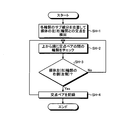
そして、手画像除去部102hは、媒体領域の画像から手領域の画像を除去するため、媒体領域の輪郭である媒体輪郭と手輪郭との交点ペアを検出する(ステップSB-14)。ここで、図19は、交点ペア検出処理のサブルーチンを示すフローチャートである。また、図20は、交点ペア検出処理における交点ペアを模式的に示す図である。
図19および図20に示すように、手画像除去部102hは、手輪郭の各輪郭のサブ線分を走査して、媒体の左(右)輪郭との交点を検出する(ステップSH-1)。
そして、手画像除去部102hは、図20に示すように、上から順に、交点ペアの間の手輪郭が内側にあるか外側にあるかをチェックする(ステップSH-2)。
そして、手画像除去部102hは、交点ペアの媒体左輪郭の右側に、手輪郭がある場合に(ステップSH-3,Yes)、当該交点ペアを記憶部106に記録する(ステップSH-4)。なお、媒体右輪郭も同様に、手画像除去部102hは、交点ペアの媒体右輪郭の左側に、手輪郭がある場合に(ステップSH-3,Yes)、当該交点ペアを記憶部106に記録する(ステップSH-4)。
そして、手画像除去部102hは、交点ペアを記録し、未チェックの交点ペアがある場合(ステップSH-4)または交点ペアの媒体左(右)輪郭の右側(左側)に手輪郭がない場合(ステップSH-3,No)、ステップSH-2に処理を戻し、次の交点ペアについてチェックを行う。これにより、媒体領域にある手領域の外側輪郭を交点ペアにより特定することができる。
再び図9に戻り、手画像除去部102hは、記録した交点ペアを結んだ線と元の手領域で囲まれる、媒体領域内の手領域の画像を塗りつぶす(ステップSB-15)。例えば、手画像除去部102hは、媒体領域内の手領域の画像周辺の媒体画像の色情報に基づいて、当該手領域の画像を塗りつぶす色を決定してもよい。
そして、加工画像記録部102iは、公知の歪み補正手法にて、歪み補正処理を行う(ステップSB-16)。ここで、図21は、以上の処理にて加工された、手領域の画像が除去された歪みのない媒体の加工画像を示す図である。図21に示すように、歪み補正処理により、媒体が撓むことによる歪みが補正されている。
そして、加工画像記録部102iは、加工後の画像データを加工画像データファイル106bに格納し(ステップSB-17)、処理を終える。
以上が、本実施形態のオーバヘッドスキャナ装置100における具体化処理の一例である。なお、上述した具体化処理においては、左右見開き2ページの画像が読み取られる場合の1回の処理の流れについて説明したが、上下の見開き2ページの媒体など、他の様式の媒体について適用してもよいものである。
[3.本実施形態のまとめ、及び他の実施形態]
以上、本実施形態によれば、オーバヘッドスキャナ装置100は、複数の画像を連続して取得し、連続的に取得される画像に基づいて、媒体周辺の背景モデルを更新し、背景モデルからの変動量を計算し、変動量に基づいて手領域を抽出し、媒体の画像から手領域の画像を除去する。これにより、特定の色で手領域を検出することなく、常時、学習により更新する背景モデルにて、手領域を検出するので、利用者が手袋をはめて操作している場合や、指色と背景となる本の色が似ている場合などにおいても、誤検出を防止して、精度よく手領域の画像を除去することができる。
以上、本実施形態によれば、オーバヘッドスキャナ装置100は、複数の画像を連続して取得し、連続的に取得される画像に基づいて、媒体周辺の背景モデルを更新し、背景モデルからの変動量を計算し、変動量に基づいて手領域を抽出し、媒体の画像から手領域の画像を除去する。これにより、特定の色で手領域を検出することなく、常時、学習により更新する背景モデルにて、手領域を検出するので、利用者が手袋をはめて操作している場合や、指色と背景となる本の色が似ている場合などにおいても、誤検出を防止して、精度よく手領域の画像を除去することができる。
また、本実施形態によれば、エリアセンサ22を介して取得更新されるエリア画像から、背景モデルを構築し、エリアセンサ22を介して取得されるエリア画像の座標系から、画像センサ13を介して取得されるリニア画像の座標系に変換し、媒体画像上にマッピングされた手領域の画像を除去する。これにより、媒体の画像は高精細なリニア画像で得ながら、異なる座標系のエリア画像による背景モデルの変動量を手領域の検出に用いることができる。
また、本実施形態によれば、画像センサ13によるスキャンスイッチ10を押下した指の色情報に基づいて、背景モデルからの変動量に基づいて手領域を抽出する際のノイズを除去するので、手で媒体を押さえるときに媒体を伸ばすような媒体の微動があっても、ノイズを適切に除去することができる。
また、本実施形態によれば、媒体周辺に手を検出した場合に、背景モデルの更新を中止するので、手領域をも背景として学習することを適切に防ぐことができる。
また、本実施形態によれば、前景画像から色モデルを生成し、色モデルに当てはまるピクセルを検出して、手領域の2値画像を取得するので、媒体領域を含むリニア画像中の手領域を適切に検出することができる。
また、本実施形態によれば、媒体画像の上下から走査して検出した輝度の変化点に基づいて、媒体領域の輪郭を取得するので、適切に媒体領域の輪郭を取得することができる。
さらに、本発明は、上述した実施形態以外にも、特許請求の範囲に記載した技術的思想の範囲内において種々の異なる実施形態にて実施されてよいものである。例えば、エリアセンサ22は、赤外領域以外の波長領域の光を検出してもよい。また、オーバヘッドスキャナ装置100がスタンドアローンの形態で処理を行う場合を一例に説明したが、オーバヘッドスキャナ装置100とは別筐体のクライアント端末からの要求に応じて処理を行い、その処理結果を当該クライアント端末に返却するようにしてもよい。また、実施形態において説明した各処理のうち、自動的に行われるものとして説明した処理の全部または一部を手動的に行うこともでき、あるいは、手動的に行われるものとして説明した処理の全部または一部を公知の方法で自動的に行うこともできる。このほか、上記文献中や図面中で示した処理手順、制御手順、具体的名称、各処理の登録データを含む情報、画面例、データベース構成については、特記する場合を除いて任意に変更することができる。
また、オーバヘッドスキャナ装置100に関して、図示の各構成要素は機能概念的なものであり、必ずしも物理的に図示の如く構成されていることを要しない。例えば、オーバヘッドスキャナ装置100の各装置が備える処理機能、特に制御部102にて行われる各処理機能については、その全部または任意の一部を、CPU(Central Processing Unit)および当該CPUにて解釈実行されるプログラムにて実現してもよく、また、ワイヤードロジックによるハードウェアとして実現してもよい。尚、プログラムは、後述する記録媒体に記録されており、必要に応じてオーバヘッドスキャナ装置100に機械的に読み取られる。すなわち、ROMまたはHDDなどの記憶部106などには、各種処理を行うためのコンピュータプログラムが記録されている。このコンピュータプログラムは、RAMにロードされることによって実行され、CPUと協働して制御部を構成する。また、このコンピュータプログラムは、オーバヘッドスキャナ装置100に対して任意のネットワークを介して接続されたアプリケーションプログラムサーバに記憶されていてもよく、必要に応じてその全部または一部をダウンロードすることも可能である。
また、本発明に係るプログラムを、コンピュータ読み取り可能な記録媒体に格納してもよく、また、プログラム製品として構成することもできる。ここで、この「記録媒体」とは、メモリーカード、USBメモリ、SDカード、フレキシブルディスク、光磁気ディスク、ROM、EPROM、EEPROM、CD-ROM、MO、DVD、および、Blu-ray(登録商標) Disc等の任意の「可搬用の物理媒体」を含むものとする。また、「プログラム」とは、任意の言語や記述方法にて記述されたデータ処理方法であり、ソースコードやバイナリコード等の形式を問わない。なお、「プログラム」は必ずしも単一的に構成されるものに限られず、複数のモジュールやライブラリとして分散構成されるものや、OS(Operating System)に代表される別個のプログラムと協働してその機能を達成するものをも含む。なお、実施形態に示した各装置において記録媒体を読み取るための具体的な構成、読み取り手順、あるいは、読み取り後のインストール手順等については、周知の構成や手順を用いることができる。
記憶部106に格納される各種のデータベース等(画像データ一時ファイル106a、加工画像データファイル106b、手ファイル106c、および背景ファイル106d)は、RAM、ROM等のメモリ装置、ハードディスク等の固定ディスク装置、フレキシブルディスク、および、光ディスク等のストレージ手段であり、各種処理に用いる各種のプログラム、テーブル、および、データベース等を格納する。
また、オーバヘッドスキャナ装置100は、既知のパーソナルコンピュータ、ワークステーション等の情報処理装置として構成してもよく、また、該情報処理装置に任意の周辺装置を接続して構成してもよい。また、オーバヘッドスキャナ装置100は、該情報処理装置に本発明の方法を実現させるソフトウェア(プログラム、データ等を含む)を実装することにより実現してもよい。更に、装置の分散・統合の具体的形態は図示するものに限られず、その全部または一部を、各種の付加等に応じて、または、機能負荷に応じて、任意の単位で機能的または物理的に分散・統合して構成することができる。すなわち、上述した実施形態を任意に組み合わせて実施してもよく、実施形態を選択的に実施してもよい。
以上のように、本発明に係るオーバヘッドスキャナ装置、画像取得方法、および、プログラムは、産業上の多くの分野、特にスキャナで読み取った画像を扱う画像処理分野で実施することができ、極めて有用である。
100 オーバヘッドスキャナ装置
102 制御部
102a エリア画像取得部
102b 背景モデル更新部
102c 背景変動量計算部
102d 座標変換部
102e 媒体画像取得部
102f 媒体領域抽出部
102g 手領域抽出部
102h 手画像除去部
102i 加工画像記録部
106 記憶部
106a 画像データ一時ファイル
106b 加工画像データファイル
106c 手ファイル
102d 背景ファイル
108 入出力インターフェース部
110 リニア撮像部
11 コントローラ
12 モータ
13 画像センサ
14 A/Dコンバータ
120 エリア撮像部
21 コントローラ
22 エリアセンサ
23 A/Dコンバータ
140 光源
102 制御部
102a エリア画像取得部
102b 背景モデル更新部
102c 背景変動量計算部
102d 座標変換部
102e 媒体画像取得部
102f 媒体領域抽出部
102g 手領域抽出部
102h 手画像除去部
102i 加工画像記録部
106 記憶部
106a 画像データ一時ファイル
106b 加工画像データファイル
106c 手ファイル
102d 背景ファイル
108 入出力インターフェース部
110 リニア撮像部
11 コントローラ
12 モータ
13 画像センサ
14 A/Dコンバータ
120 エリア撮像部
21 コントローラ
22 エリアセンサ
23 A/Dコンバータ
140 光源
Claims (8)
- 複数の画像を連続して取得する画像取得手段と、
前記画像取得手段により連続的に取得される前記画像に基づいて、媒体周辺の背景モデルを更新する背景モデル更新手段と、
前記背景モデルからの変動量を計算する背景変動量計算手段と、
前記変動量に基づいて、手領域を抽出する手領域抽出手段と、
前記媒体の画像から手領域の画像を除去する手画像除去手段と、
を備えたことを特徴とするオーバヘッドスキャナ装置。 - 請求項1に記載のオーバヘッドスキャナ装置において、
エリアセンサと媒体画像センサを備え、
前記エリアセンサを介して取得される画像の座標系から、前記媒体画像センサを介して取得される媒体画像の座標系に変換する座標変換手段を更に備え、
前記背景モデル更新手段は、
エリアセンサを介して取得更新される画像から、前記背景モデルを構築し、
前記手画像除去手段は、
前記座標変換手段により媒体画像上にマッピングされた手領域の画像を除去することを特徴とするオーバヘッドスキャナ装置。 - 請求項1または2に記載のオーバヘッドスキャナ装置において、
前記手領域抽出手段は、
前記媒体画像センサによる読取開始ボタンを押下した指の色情報に基づいて、前記背景モデルからの変動量に基づいて手領域を抽出する際のノイズを除去することを特徴とするオーバヘッドスキャナ装置。 - 請求項1乃至3のいずれか一つに記載のオーバヘッドスキャナ装置において、
前記背景モデル更新手段は、
前記媒体周辺に手を検出した場合に、前記背景モデルの更新を中止することを特徴とするオーバヘッドスキャナ装置。 - 請求項1乃至4のいずれか一つに記載のオーバヘッドスキャナ装置において、
前記手領域抽出手段は、
前景画像から色モデルを生成し、色モデルに当てはまるピクセルを検出して、前記手領域の2値画像を取得することを特徴とするオーバヘッドスキャナ装置。 - 請求項1乃至5のいずれか一つに記載のオーバヘッドスキャナ装置において、
前記媒体画像の上下から走査して検出した輝度の変化点に基づいて、媒体領域の輪郭を取得する媒体領域抽出手段を更に備えたことを特徴とするオーバヘッドスキャナ装置。 - オーバヘッドスキャナ装置の制御部で実行される、
複数の画像を連続して取得する画像取得ステップと、
前記画像取得ステップにて連続的に取得される前記画像に基づいて、媒体周辺の背景モデルを更新する背景モデル更新ステップと、
前記背景モデルからの変動量を計算する背景変動量計算ステップと、
前記変動量に基づいて、手領域を抽出する手領域抽出ステップと、
前記媒体の画像から手領域の画像を除去する手画像除去ステップと、
を含むことを特徴とする画像取得方法。 - 複数の画像を連続して取得する画像取得ステップと、
前記画像取得ステップにて連続的に取得される前記画像に基づいて、媒体周辺の背景モデルを更新する背景モデル更新ステップと、
前記背景モデルからの変動量を計算する背景変動量計算ステップと、
前記変動量に基づいて、手領域を抽出する手領域抽出ステップと、
前記媒体の画像から手領域の画像を除去する手画像除去ステップと、
をオーバヘッドスキャナ装置の制御部に実行させるためのプログラム。
Priority Applications (2)
| Application Number | Priority Date | Filing Date | Title |
|---|---|---|---|
| PCT/JP2014/053514 WO2015121981A1 (ja) | 2014-02-14 | 2014-02-14 | オーバヘッドスキャナ装置、画像取得方法、および、プログラム |
| JP2015562651A JP6181779B2 (ja) | 2014-02-14 | 2014-02-14 | オーバヘッドスキャナ装置、画像取得方法、および、プログラム |
Applications Claiming Priority (1)
| Application Number | Priority Date | Filing Date | Title |
|---|---|---|---|
| PCT/JP2014/053514 WO2015121981A1 (ja) | 2014-02-14 | 2014-02-14 | オーバヘッドスキャナ装置、画像取得方法、および、プログラム |
Publications (1)
| Publication Number | Publication Date |
|---|---|
| WO2015121981A1 true WO2015121981A1 (ja) | 2015-08-20 |
Family
ID=53799747
Family Applications (1)
| Application Number | Title | Priority Date | Filing Date |
|---|---|---|---|
| PCT/JP2014/053514 Ceased WO2015121981A1 (ja) | 2014-02-14 | 2014-02-14 | オーバヘッドスキャナ装置、画像取得方法、および、プログラム |
Country Status (2)
| Country | Link |
|---|---|
| JP (1) | JP6181779B2 (ja) |
| WO (1) | WO2015121981A1 (ja) |
Cited By (2)
| Publication number | Priority date | Publication date | Assignee | Title |
|---|---|---|---|---|
| CN110954538A (zh) * | 2018-09-25 | 2020-04-03 | 柯尼卡美能达株式会社 | 图像检查系统、图像检查方法、以及储存有图像检查程序的计算机能够读取的记录介质 |
| WO2021121302A1 (zh) * | 2019-12-19 | 2021-06-24 | 华为技术有限公司 | 一种视频采集控制方法、电子设备、计算机可读存储介质 |
Citations (3)
| Publication number | Priority date | Publication date | Assignee | Title |
|---|---|---|---|---|
| JPH0535874A (ja) * | 1991-07-29 | 1993-02-12 | Nippon Telegr & Teleph Corp <Ntt> | 物体像の抽出処理方法 |
| JP2012243120A (ja) * | 2011-05-20 | 2012-12-10 | Fujitsu Frontech Ltd | 画像処理プログラム、画像処理装置及び画像処理方法 |
| JP2013247531A (ja) * | 2012-05-25 | 2013-12-09 | Panasonic Corp | 画像処理装置およびこれを備えた原稿読取システム |
-
2014
- 2014-02-14 WO PCT/JP2014/053514 patent/WO2015121981A1/ja not_active Ceased
- 2014-02-14 JP JP2015562651A patent/JP6181779B2/ja active Active
Patent Citations (3)
| Publication number | Priority date | Publication date | Assignee | Title |
|---|---|---|---|---|
| JPH0535874A (ja) * | 1991-07-29 | 1993-02-12 | Nippon Telegr & Teleph Corp <Ntt> | 物体像の抽出処理方法 |
| JP2012243120A (ja) * | 2011-05-20 | 2012-12-10 | Fujitsu Frontech Ltd | 画像処理プログラム、画像処理装置及び画像処理方法 |
| JP2013247531A (ja) * | 2012-05-25 | 2013-12-09 | Panasonic Corp | 画像処理装置およびこれを備えた原稿読取システム |
Cited By (2)
| Publication number | Priority date | Publication date | Assignee | Title |
|---|---|---|---|---|
| CN110954538A (zh) * | 2018-09-25 | 2020-04-03 | 柯尼卡美能达株式会社 | 图像检查系统、图像检查方法、以及储存有图像检查程序的计算机能够读取的记录介质 |
| WO2021121302A1 (zh) * | 2019-12-19 | 2021-06-24 | 华为技术有限公司 | 一种视频采集控制方法、电子设备、计算机可读存储介质 |
Also Published As
| Publication number | Publication date |
|---|---|
| JPWO2015121981A1 (ja) | 2017-03-30 |
| JP6181779B2 (ja) | 2017-08-16 |
Similar Documents
| Publication | Publication Date | Title |
|---|---|---|
| JP6052997B2 (ja) | オーバヘッドスキャナ装置、画像取得方法、および、プログラム | |
| JP5364845B2 (ja) | オーバーヘッドスキャナ装置、画像処理方法、および、プログラム | |
| US9665168B2 (en) | Image processing apparatus, information processing method, and program | |
| CN110557515B (zh) | 图像处理装置、图像处理方法和存储介质 | |
| JP5749367B1 (ja) | 画像読取装置、画像処理方法、および、プログラム | |
| JP2014017673A (ja) | 画像処理装置及びその方法とプログラム | |
| JP6122988B1 (ja) | 画像処理装置、画像処理方法、および、プログラム | |
| US7864985B1 (en) | Automatic operator-induced artifact detection in document images | |
| JP6564136B2 (ja) | 画像処理装置、画像処理方法、および、プログラム | |
| JP6181779B2 (ja) | オーバヘッドスキャナ装置、画像取得方法、および、プログラム | |
| JP5462522B2 (ja) | 画像処理装置、画像処理方法、当該画像処理方法をコンピュータに実現させるためのプログラム | |
| JP6194407B2 (ja) | 原稿歪み補正装置、原稿歪み補正方法、および、プログラム | |
| US8422785B2 (en) | Image processing apparatus, image processing method, and program | |
| JP6181778B2 (ja) | オーバーヘッド型画像読取装置、画像処理方法、および、プログラム | |
| JP6974791B2 (ja) | 画像処理装置、および、コンピュータプログラム | |
| JP6194408B2 (ja) | クロッピング装置、クロッピング方法、および、プログラム | |
| JP2010010839A (ja) | 画像読取装置、その処理方法及びプログラム | |
| JP6859779B2 (ja) | 画像読取装置、画像読取方法および画像読取プログラム | |
| JP2013247531A (ja) | 画像処理装置およびこれを備えた原稿読取システム | |
| WO2015140935A1 (ja) | オーバーヘッド型画像読取装置、画像処理方法、および、プログラム | |
| JP2013251779A (ja) | 画像処理装置及び画像処理方法 | |
| JP2025118004A (ja) | 読取装置 | |
| US20200314258A1 (en) | Image processing system, image processing apparatus, and image processing method | |
| JP6905210B2 (ja) | 画像処理装置、および、コンピュータプログラム | |
| KR20250009044A (ko) | 휴대기기를 이용한 도장 스캔 방법 및 장치 |
Legal Events
| Date | Code | Title | Description |
|---|---|---|---|
| 121 | Ep: the epo has been informed by wipo that ep was designated in this application |
Ref document number: 14882247 Country of ref document: EP Kind code of ref document: A1 |
|
| ENP | Entry into the national phase |
Ref document number: 2015562651 Country of ref document: JP Kind code of ref document: A |
|
| NENP | Non-entry into the national phase |
Ref country code: DE |
|
| 122 | Ep: pct application non-entry in european phase |
Ref document number: 14882247 Country of ref document: EP Kind code of ref document: A1 |