WO2015116387A1 - Systems, methods and devices for application specific routing in dual connectivity - Google Patents

Systems, methods and devices for application specific routing in dual connectivity Download PDF

Info

Publication number
WO2015116387A1
WO2015116387A1 PCT/US2015/011427 US2015011427W WO2015116387A1 WO 2015116387 A1 WO2015116387 A1 WO 2015116387A1 US 2015011427 W US2015011427 W US 2015011427W WO 2015116387 A1 WO2015116387 A1 WO 2015116387A1
Authority
WO
WIPO (PCT)
Prior art keywords
bearer
packets
application
wireless
packet
Prior art date
Application number
PCT/US2015/011427
Other languages
French (fr)
Inventor
Candy YIU
Ana Lucia A. Pinheiro
Original Assignee
Intel IP Corporation
Priority date (The priority date is an assumption and is not a legal conclusion. Google has not performed a legal analysis and makes no representation as to the accuracy of the date listed.)
Filing date
Publication date
Application filed by Intel IP Corporation filed Critical Intel IP Corporation
Priority to JP2016561997A priority Critical patent/JP6342514B2/en
Priority to CN201580003239.7A priority patent/CN106063330B/en
Priority to EP15743766.6A priority patent/EP3100517B8/en
Publication of WO2015116387A1 publication Critical patent/WO2015116387A1/en

Links

Classifications

    • HELECTRICITY
    • H04ELECTRIC COMMUNICATION TECHNIQUE
    • H04WWIRELESS COMMUNICATION NETWORKS
    • H04W40/00Communication routing or communication path finding
    • H04W40/02Communication route or path selection, e.g. power-based or shortest path routing
    • HELECTRICITY
    • H04ELECTRIC COMMUNICATION TECHNIQUE
    • H04WWIRELESS COMMUNICATION NETWORKS
    • H04W36/00Hand-off or reselection arrangements
    • H04W36/0005Control or signalling for completing the hand-off
    • H04W36/0055Transmission or use of information for re-establishing the radio link
    • H04W36/0069Transmission or use of information for re-establishing the radio link in case of dual connectivity, e.g. decoupled uplink/downlink
    • HELECTRICITY
    • H04ELECTRIC COMMUNICATION TECHNIQUE
    • H04WWIRELESS COMMUNICATION NETWORKS
    • H04W76/00Connection management
    • H04W76/10Connection setup
    • H04W76/15Setup of multiple wireless link connections
    • HELECTRICITY
    • H04ELECTRIC COMMUNICATION TECHNIQUE
    • H04WWIRELESS COMMUNICATION NETWORKS
    • H04W80/00Wireless network protocols or protocol adaptations to wireless operation
    • H04W80/08Upper layer protocols
    • HELECTRICITY
    • H04ELECTRIC COMMUNICATION TECHNIQUE
    • H04WWIRELESS COMMUNICATION NETWORKS
    • H04W36/00Hand-off or reselection arrangements
    • H04W36/0005Control or signalling for completing the hand-off
    • H04W36/0055Transmission or use of information for re-establishing the radio link
    • H04W36/0069Transmission or use of information for re-establishing the radio link in case of dual connectivity, e.g. decoupled uplink/downlink
    • H04W36/00698Transmission or use of information for re-establishing the radio link in case of dual connectivity, e.g. decoupled uplink/downlink using different RATs
    • HELECTRICITY
    • H04ELECTRIC COMMUNICATION TECHNIQUE
    • H04WWIRELESS COMMUNICATION NETWORKS
    • H04W76/00Connection management
    • H04W76/10Connection setup
    • H04W76/15Setup of multiple wireless link connections
    • H04W76/16Involving different core network technologies, e.g. a packet-switched [PS] bearer in combination with a circuit-switched [CS] bearer
    • HELECTRICITY
    • H04ELECTRIC COMMUNICATION TECHNIQUE
    • H04WWIRELESS COMMUNICATION NETWORKS
    • H04W84/00Network topologies
    • H04W84/02Hierarchically pre-organised networks, e.g. paging networks, cellular networks, WLAN [Wireless Local Area Network] or WLL [Wireless Local Loop]
    • H04W84/10Small scale networks; Flat hierarchical networks
    • H04W84/12WLAN [Wireless Local Area Networks]
    • HELECTRICITY
    • H04ELECTRIC COMMUNICATION TECHNIQUE
    • H04WWIRELESS COMMUNICATION NETWORKS
    • H04W88/00Devices specially adapted for wireless communication networks, e.g. terminals, base stations or access point devices
    • H04W88/02Terminal devices
    • H04W88/06Terminal devices adapted for operation in multiple networks or having at least two operational modes, e.g. multi-mode terminals

Definitions

  • the present disclosure relates to dual connectivity in wireless devices.
  • Figure 1 is a diagram illustrating a wireless dual connectivity system consistent with embodiments disclosed herein.
  • Figure 2 is a diagram illustrating a protocol stack in single connectivity consistent with embodiments disclosed herein.
  • Figure 3 is a diagram of a protocol stack in dual connectivity consistent with embodiments disclosed herein.
  • Figure 4 is a diagram of an alternate protocol stack in dual connectivity consistent with embodiments disclosed herein.
  • Figure 5 is diagram illustrating filtering based on application consistent with embodiments disclosed herein.
  • FIG. 6 is a diagram illustrating multiple traffic flow template (TFT) assignment consistent with embodiments disclosed herein.
  • Figure 7 is a diagram illustrating a wireless communication system consistent with embodiments disclosed herein.
  • FIG. 8 is a data flow diagram illustrating data flow of an evolved packet core (EPC) in a dual connectivity environment consistent with embodiments disclosed herein.
  • EPC evolved packet core
  • Figure 9 is a data flow diagram illustrating data flow between a UE and Serving Gateway/Packet Data Network (PDN) Gateway (S/P-GW) in dual connectivity consistent with embodiments disclosed herein.
  • Figure 10 is a flow chart illustrating a method for application specific routing consistent with embodiments disclosed herein.
  • Figure 11 is a schematic diagram of a mobile device consistent with embodiments disclosed herein.
  • an evolved Node B (also commonly denoted as Node B, enhanced Node B, eNodeB, or eNB) can split a bearer between a master eNB (MeNB) and a secondary wireless connection (such as a secondary eNB (SeNB)).
  • UE User equipment
  • UE can connect to both a MeNB and a SeNB and split a bearer based on application type.
  • packet routing can be based on other attributes (such as IP address, application, application type, etc.).
  • This dual connectivity allows MeNB to schedule data forwarding based on application. Data packets assigned to a bearer can be divided among the MeNB and SeNB based on desirable attributes of the MeNB and SeNB for an application (such as reliability or speed).
  • a UE is connected to one eNB.
  • the UE can connect to more than one eNB (referred to here as MeNB and SeNB) simultaneously to increase a UE data rate and offload transmissions to Macro cells.
  • MeNB and SeNB eNB
  • the MeNB determines to add a SeNB and selected bearers are serviced through the MeNB and others through the SeNB.
  • an eNB does not have knowledge of an application type such as voice, video or SMS. Instead, each bearer is associated with a quality of service class identifier (QCI) for quality of service (QoS).
  • QCI quality of service class identifier
  • QoS quality of service
  • the eNB has very limited ability today to forward data based on the applications mapped to the bearers.
  • a QCI table can be extended; (2) an application table can be created; (3) TFTs can be extended; (4) multiple TFTs can be used for a single bearer and (5) other networks can be used.
  • a packet splitter (such as a packet filter, packet router, packet inspector, etc.) can be added before, in or after a packet data convergence protocol (PDCP) layer.
  • a filter is added before a PDCP layer (such as on top of the PDCP layer or in a gateway such as a serving gateway (S-GW, SGW)) or a serving gateway/packet data network (PND) gateway (SPGW or S/P-GW).
  • a filter resides in (or with) the PDCP layer.
  • the packets can routed through a wireless link based on their association with an application (or part of an application).
  • a packet filter can be configured to route a voice portion of a video chat application through a MeNB, while a video portion can be configured to be routed through a SeNB.
  • one given bearer can be split between the MeNB and SeNB.
  • a packet filter can split a stream of packets from one bearer to MeNB and SeNB based on characteristics (IP address, extended QCI level, application table, etc.).
  • the filtering is based on an application table.
  • An application table can contain a list of applications matched with IP addresses. This table can then be used by a packet filter to determine which wireless link, connection, eNB, medium or set of frequencies should be used to transmit a packet.
  • transmission over a wireless link can be expressed in different ways. In many instances, transmission can be over a wireless link, connection, eNB, medium or set of frequencies. While specific embodiments may be described using one set of terminology, it should be recognized that other terminology can be applicable.
  • a wireless medium is a link between two wireless systems that can transmit information. More than one wireless mediums (or media) can exist, as each medium is associated with a link (such as different wireless frequencies, different link technologies, etc.)
  • the filtering can be based on an extended QCI table.
  • a QCI table can be extended to include applications. Each application type can be assigned a QCI value.
  • a packet filter can examine a QCI value of the packet within a stream and make a determination of the routing of the packet over a primary wireless link or secondary wireless link.
  • current traffic flow templates can be extended to allow multiple TFTs to be mapped to a single bearer.
  • a network can set two or more TFTs to map to a single bearer. Packets in the split bearer can map into one of the two TFTs.
  • the packet filter is not limited to long term evolution (LTE) networks, but can be applied to other links, such as a wireless local area network (WLAN) link.
  • LTE long term evolution
  • WLAN wireless local area network
  • an eNB can configure associated TFTs and packet filters on the LTE bearer and a WLAN link.
  • multiple TFTs can be configured for a single bearer.
  • a bearer can be established with a first TFT.
  • a second TFT can be created such that packets that are within the first TFT and also match a second TFT can be routed according to the second TFT.
  • This data routing can use wireless mobile communication technology between a UE and one or more base stations.
  • Wireless mobile communication technology uses various standards and protocols to transmit data between a base station and a wireless mobile device.
  • Wireless communication system standards and protocols can include the 3rd Generation Partnership Project (3GPP) long term evolution (LTE); the Institute of Electrical and
  • Mobile broadband networks can include various high speed data technologies, such as 3 GPP LTE systems.
  • RANs radio access networks
  • the base station can include Evolved Universal Terrestrial Radio Access Network (E-UTRAN) Node Bs (also commonly denoted as evolved Node Bs, enhanced Node Bs, eNodeBs, or eNBs) and/or Radio Network
  • E-UTRAN Evolved Universal Terrestrial Radio Access Network
  • Node Bs also commonly denoted as evolved Node Bs, enhanced Node Bs, eNodeBs, or eNBs
  • Radio Network Evolved Universal Terrestrial Radio Access Network
  • RNCs in an E-UTRAN, which communicate with a wireless communication device, known as user equipment (UE).
  • UE user equipment
  • the eNBs allow the UE to connect to further network infrastructure, such as an evolved packet core (EPC), which can include gateways (such as an S-GW) and applications and/or services (including Internet access).
  • EPC evolved packet core
  • gateways such as an S-GW
  • applications and/or services including Internet access
  • FIG. 1 shows an example of a portion of a radio access network (RAN) system 100 that includes a single cellular air interface (such as an LTE/LTE- Advanced access link) being provided between the anchor tower 104 (such as an eNB) and the UE 102 (i.e., on Access Link A 112), and an air interface (a supplemental network interface such as a small cell based interface or wireless local area network (WLAN) based interface) being provided between the small cell transceiver 106 and the UE 102 (i.e., on Access Link B 114).
  • UE 102 is located within macro cell coverage 108 and small cell coverage area 110.
  • Anchor tower 104 determines that connection with a small cell transceiver 106 will be beneficial to a user of the UE 102.
  • the UE 102 can retain Access Link A 112 to anchor tower 104.
  • the anchor tower 104 and UE 102 can offload some or part of wireless services onto Access Link B 114.
  • Access Link A 112 and Access Link B 114 use a same frequency and technology.
  • Access Link A 112 and Access Link B 114 use different frequencies (e.g., LTE licensed frequencies and unlicensed frequencies) and different link technology (e.g., LTE and WLAN).
  • Access Link A 112 and Access Link B 114 use different frequencies and similar link technology (e.g., LTE and LTE over mm Wave).
  • Data can be routed over Access Link A 112 or Access Link B based on a packet filter determination.
  • a gateway in the network infrastructure 118 can transmit packets over a backhaul link 116 to a MeNB (such as anchor tower 104).
  • the MeNB can determine that the UE 102 should connect to a SeNB (such as small cell transceiver 106).
  • the MeNB can instruct the UE 102 to connect to the SeNB.
  • a packet filter can be enabled on the MeNB and SeNB. Packets can be routed through the MeNB or SeNB based on application. A packet can be received by the MeNB and then routed to the SeNB.
  • a packet filter can operate above the level of the eNB and routed to the MeNB or SeNB based on an identifier that correlates with an application.
  • Figures 2-4 show various protocol stacks that a wireless system (such as an EPC or UE) can use to communicate over a wireless medium.
  • Figure 2 shows a single connectivity embodiment.
  • Figure 3 shows an embodiment in what is known as option 1 A in a dual connectivity environment and includes packet routing before the PDCP layer.
  • Figure 4 shows an embodiment in what is known as option 3C in a dual connectivity environment and includes packet routing in the PDCP layer, which can also allow a bearer split.
  • Figure 2 shows a protocol architecture in single connectivity embodiment.
  • a UE such as a UE 102 from Figure 1
  • the network will set up a bearer based on QCI and data will be sent via a different bearer based on the QCI.
  • Packets received from the application layer 202 on a user plane are provided to the PDCP layer 208.
  • the PDCP layer can add a PDCP header, perform IP header compression, transfer user data and maintain sequence numbers for radio bearers. After it operates on packets, the PDCP layer 208 provides the packet to a radio link control (RLC) layer 210.
  • RLC radio link control
  • the RLC layer 210 includes functionality to provide an automatic repeat request (ARQ) fragmentation protocol; transfer of upper layer protocol data units (PDUs);
  • RLC service data units SDUs
  • re- segmentation of RLC data PDUs RLC data units
  • in-sequence delivery of upper layer PDUs re-sequence delivery of upper layer PDUs
  • duplicate detection, protocol error detection and recovery RLC SDU discard and/or RLC re- establishment.
  • RLC SDU RLC service data units
  • MAC medium access control
  • the MAC layer 212 can provide mapping between logical channels and transport channels, multiplexing/demultiplexing of MAC SDUs belonging to logical channels into/from transport blocks to/from the physical (PHY) layer 214 on transport channels, error correction through hybrid automatic repeat request (HARQ), priority handling between logical channels, and priority handling between UEs by dynamic scheduling and/or transport format selection.
  • the MAC layer 212 After the MAC layer 212 operates on packets, the MAC layer 212 provides the packets to the PHY layer 214. Thy PHY layer 214 translates the packets received from the MAC layer 212 into electrical signals to transmit over a wireless medium.
  • Packets can also be routed through a control plane.
  • Control information can be passed from the application layer 202 to a mobility management entity (MME) layer 204.
  • MME mobility management entity
  • the MME layer 204 can provide services such as bearer activation/deactivation, paging, tagging and user authentication.
  • Control information can then be passed from the MME layer 204 to a radio resource layer (RRC) 206.
  • RRC layer 206 can provide functions that include broadcasting system information related to non-access stratum (NAS) or access stratum (AS), paging, configuring RRC connections between UE and E-UTRAN, security functions, configuring of radio bearers, mobility functions, QoS management and UE measurement reporting.
  • NAS non-access stratum
  • AS access stratum
  • architecture option 1 A is shown in Figure 3 without a bearer split and option 3C is shown in Figure 4 with a bearer split.
  • a UE is connected to a MeNB 404 and a SeNB 414.
  • An application based filter can be added to split incoming data 412 into two data flows (one flow goes to MeNB and one flow goes to SeNB).
  • This filter can reside in PDCP layer 416 in option 3C shown in Figure 4 or before PDCP layers 306 and 316 (e.g., on top of a PDCP layer) in option 1 A shown in Figure 3, or even in the S-GW (not shown).
  • This filter can be configured (such as by the MeNB 404 or the MME).
  • the filter can be pre- configured (such as selecting a pre-made filter based on known or predicted application demands) or configured upon enablement (such as by receiving configuration information by current applications).
  • Figure 4 shows an embodiment of a protocol stack that receives data 402 and 412 from two bearers, one of which is split (the bearer containing data 412).
  • Data 402 travels a path through PDCP layer 406 to RLC layer 408 to MAC layer 410 and out through a PHY layer of the MeNB 404.
  • Data 412 is filtered at the PDCP layer 416 by a packet filter. Some data passes through the MeNB 404 through PDCP layer 416, RLC layer 422, MAC layer 424 and out through a PHY layer of the MeNB 404.
  • Part of data 412 is split from MeNB to SeNB at PDCP layer 416 and sent over link Xn 426 to SeNB 414.
  • the SeNB 414 then passes the data through RLC layer 418, MAC layer 420 and out through a PHY layer of the SeNB 414.
  • FIG. 5 an example of a filter 506 is shown splitting a same bearer 504 into two flows based on the application in system 500.
  • Such application data flow is sent to a UE 512 via different eNBs 508 and 510 through dual connectivity.
  • the routing of the flow can be based on a load and a coverage of each eNB 508 and 510. For instance, a MeNB 508 is selected to have more reliable and larger coverage than a selected SeNB 510. However, the MeNB 508 can be more overloaded than SeNB 510.
  • Figures 6 through 9 show example embodiments that use application dependent filtering in dual connectivity for application specific routing.
  • Figures 6 and 7 show examples of high-level views of systems using application specific routing
  • Figures 8 and 9 show more detailed embodiments of routing.
  • Five example embodiments are described below that can be used for application specific routing (although these embodiments are not meant to be exhaustive and combinations thereof can be created): (1) a QCI table can be extended; (2) an application table can be created; (3) TFTs can be extended; (4) multiple TFTs can be used for a single bearer and (5) other networks can be used. While the embodiments described herein may focus on enhancements to a MeNB, it should be recognized that these enhancements can also be applied in a P-GW (including embodiments of dual connectivity as shown in Figure 3).
  • an existing QCI table (such as Table 1) can be extended such that each application type is added into a QCI value.
  • a QCI table based embodiment for application dependent filtering more bearers will be set up.
  • a MeNB will select a bearer and offload the bearer to a SeNB.
  • Table 1 describes nine QCI classes. Additional classes can be defined for application types, such as latency tolerant game caching (e.g., background downloading of large amounts of game content) and real-time gaming updates (e.g., small amounts of real-time position and action information).
  • Using extended QCI with packet filters can allow application specific filtering.
  • This QCI could be used for a dedicated "premium bearer" (e.g., associated with premium content) for any subscriber / subscriber group. Also in this case, the SDF aggregate's uplink / downlink packet filters are known at the point in time when the SDF aggregate is authorized. Alternatively, this QCI could be used for the default bearer of a UE/PDN for "premium subscribers.”
  • premium bearer e.g., associated with premium content
  • This QCI is typically used for the default bearer of a UE/PDN for non- privileged subscribers.
  • AMBR can be used as a "tool" to provide subscriber differentiation between subscriber groups connected to the same PDN with the same QCI on the default bearer.
  • an application table can be used as shown in Table 2.
  • An application filter like functionality is created to filter packets based on the application mapping table entries which can be pre-assigned to either MeNB or SeNB.
  • the mapping table entries are based on IP information (such as an IP address).
  • the packet filters can determine whether to route packets to a MeNB or SeNB based on the IP address information.
  • an application mapping table can provide functionality to filter data flow within the bearer (such as shown in Figure 5 in filter 506).
  • An application mapping table can map an application entry to an IP address.
  • the application table contains different applications so that an IP to application mapping can be created at the setup.
  • Table 2 is an example of the application table, but the number of applications and kind of applications should not be limited to what is shown.
  • TFTs current traffic flow templates
  • a TFT is used to define different types of application data paths using packet filters.
  • an extended TFT can filter port 80 for http traffic and send through a MeNB while other traffic is sent through a SeNB.
  • Multiple configurations can be configured to a TFT.
  • a packet filter can be use the following contents:
  • a traffic flow/packet filter can be associated to the preferred cell type.
  • One way of implementing this association between the packet filter and the preferred cell type is to associate a QoS parameter field to each packet filter identifier. This can be accomplished by adding the QoS parameters field in the "packet filter list" e.g., [3GPP TS 24.008: Core network protocols; Stage 3], as shown in Table 3 below
  • multiple TFTs can be configured to a single bearer. For example, a set of packets may satisfy the criteria of two TFTs. However, a TFT that is more restrictive can be used to determine which packets are routed to a secondary link (such as a SeNB).
  • a secondary link such as a SeNB
  • one evolved packet system (EPS) bearer maps to one TFT.
  • the network such as a MeNB
  • the network can set two or more TFTs to map to a single bearer.
  • each split bearer is associated with one of the TFTs.
  • a packet filter separates the flow into flows 608 and 610 based on application information (such as IP address or application table entry).
  • Packets 612 having a first application characteristic are associated with TFT2 604 and routed through MeNB 616.
  • Packets 614 having a second application characteristic are associated with TFT3 606 and routed through SeNB 618.
  • a TFT is configured and applied to one or more bearers that MeNB 616 decides to offload to SeNB 618.
  • This TFT is re-configured such that an application dependent packet is filtered and offloaded to SeNB 618.
  • MeNB 616 will configure TFT3 606 along with the bearer.
  • the packet filters associated in TFT3 606 have to be a subset of TFT1 602. To do that, MeNB 616 can add, delete or modify packet filters in TFT. Similarly, MeNB 616 can modify the existing TFT2 604.
  • an eNB can configure multiple TFTs for a single bearer when a SeNB is added.
  • the eNB can follow the following operations: (1) when a single bearer (denoted Bl) is established, a TFT (denoted TFT1) is configured; (2) upon adding a SeNB, bearer Bl is split into two bearers (denoted B2 and B3) (B2 is a bearer that connects to MeNB and B3 is a bearer that connects to SeNB); (3) a new TFT (denoted TFT3) is configured to B3 and this new TFT is also automatically configured to Bl; and (4) when the SeNB is released, TFT3 is removed from Bl as well.
  • An example embodiment of a split bearer system 800 can be seen in Figure 8.
  • An application server 810 creates three application specific data flows that include packets 814, 816 and 818.
  • the application server 810 transmits the packets 814, 816 and 818 through S/P- GW 812 to macro cell 822.
  • Macro cell 822 determines which packets are transmitted by the macro cell 822 to a UE and those packets are offloaded to small cell 824 for transmission to the UE.
  • Application 1 (802) creates packets 816.
  • Application 2 (804) creates packets 818.
  • Application 3 creates packets 814.
  • S/P-GW 812 receives these traffic flows and associates the flows with EPS bearers.
  • Packets 814 form part of a first EPS bearer and a first traffic flow aggregate.
  • Packets 816 and 818 form part of a second bearer and a corresponding second traffic flow aggregate.
  • One or more packet filters 820 receive these traffic flow aggregates at the macro cell 822 and route packets to a PDCP layer 826 or 834 (such as based on EPS bearer). Packets 814 are routed to PDCP layer 826 and are assigned a radio bearer. These packets 814 are then assigned a logical channel (dedicated traffic channel) in the RLC layer 828. The packets 814 then continue being processed through the MAC layer 830 (assigned a traffic channel - uplink shared channel (ULSCH)) and PHY layer 832 (assigned a physical channel - physical uplink shared channel (PUSCH)) for transmission to the UE.
  • ULSCH traffic channel - uplink shared channel
  • PHY layer 832 assigned a physical channel - physical uplink shared channel (PUSCH)
  • Packets 816 are routed to PDCP layer 834 and are assigned a radio bearer.
  • a packet filter within the PDCP layer 834 determines that packets 816 are to be transmitted by the macro cell 822 to the UE.
  • These packets 816 are then assigned a logical channel (dedicated traffic channel) in the RLC layer 835.
  • the packets 816 then continue being processed through the MAC layer 830 (assigned a traffic channel - ULSCH) and PHY layer 832 (assigned a physical channel - PUSCH) for transmission to the UE.
  • Packets 818 are routed to PDCP layer 834.
  • a packet filter within the PDCP layer 834 determines that packets 816 are to be transmitted by the small cell 824 to the UE, resulting in a bearer split.
  • the packets 818 are transmitted to small cell 824 to RLC layer 835 and are assigned a radio bearer. These packets 818 are then assigned a logical channel (dedicated traffic channel) in the RLC layer 835.
  • the packets 816 then continue being processed through the MAC layer 838 (assigned a traffic channel - ULSCH) and PHY layer 840 (assigned a physical channel - PUSCH) for transmission to the UE.
  • a system 800 can be used to transfer data (such as video information) over a high speed link (that may not be as reliable as the macro cell 822 link) through the small cell 824, that may have a small coverage area.
  • data such as video information
  • a high speed link that may not be as reliable as the macro cell 822 link
  • the small cell 824 that may have a small coverage area.
  • data corresponding to applications that need higher reliability can be transferred over the macro cell 822 link.
  • Application specific packets 922, 924 and 926 are generated from applications 902, 904 and 906 on UE 908.
  • a packet filter 936 routes packets 922, 924 to a first wireless interface for transmission to SeNB 911 based on application specific attributes.
  • the packet filter 936 routes packets 926 to a second wireless interface for transmission to MeNB 910.
  • MeNB 910 and SeNB 911 transmit the packets 922, 924 and 926 to S/P-GW 912.
  • S/P-GW 912 transmits traffic flows 962, 964 and 966 to service 914 that includes application 1 (916), application 2 (918) and application 3 (920).
  • traffic flow aggregates can be formed by TFTs (a first TFT that includes packets 922 and 924 and a second TFT that includes packets 926).
  • Packets 922 and 924 flow through PDCP layer 928 (becoming associated with a radio bearer) through RLC layer 930 (becoming associated with a logical channel (DTCH)) through MAC layer 932 (becoming associated with a transport channel (ULSCH)) and through the PHY layer 934 (becoming associated with a physical channel (PUSCH)) to be transmitted to MeNB 910.
  • Packets 926 flow through a second protocol stack through PDCP layer 938 (becoming associated with a radio bearer) through RLC layer 940 (becoming associated with a logical channel (DTCH)) through MAC layer 942 (becoming associated with a transport channel (ULSCH)) and through the PHY layer 944 (becoming associated with a physical channel (PUSCH)) to be transmitted to SeNB 911.
  • the packets 922, 924 and 926 are received by MeNB 910 and SeNB 911 and sent to S/P-GW 912, which can provide the packets to service 914 that includes application 1 (916), application 2 (918) and application 3 (920).
  • a transmission from UE 908 to SeNB 911 based on packets 926 is routed through PHY layer 946 to MAC layer 948 to RLC layer 950 to PDCP layer 952 and then through an EPS bearer to S/P-GW 912 which routes packets 926 to application 920 (becoming traffic flow 962).
  • a transmission from UE 908 to MeNB 910 based on packets 922 and 924 is routed through PHY layer 954 to MAC layer 956 to RLC layer 958 to PDCP layer 960 and then through an EPS bearer to S/P-GW 912 which routes packets 922 and 924 to applications 916 and 918 (becoming traffic flows 966 and 964).
  • UE is running a GPS voice directions application.
  • Current positioning information is reported by application 1 (902 on UE 908 and 916 on service 914).
  • Voice directions are handled by application 2 (904 on UE 908 and 918 on service 914).
  • a background map cache is provided by application 3 (906 on UE 908 and 920 on service 914).
  • Positioning information (packets 924) and voice directions (packets 924) can be timing and reliability sensitive (as routes may need to be recalculated).
  • a background map cache (packets 926) can be quickly loaded and stored for later use, allowing for high current data rates, but more unreliable connections if small updates are needed.
  • MeNB 946 can determine that application 3 (906 on UE 908 and 920 on service 914) can make use of SeNB 911 and enables SeNB 911 for use (such as a request to turn on and/or accept connections from UE 908).
  • MeNB 910 can then configure packet filters 936 or enable existing packet filters 936 (on both UE 908 and EPC, such as MeNB 910) to filter packets based on application based criteria (such as IP address, application of origin, etc.).
  • Positioning information (packets 924) and voice directions (packets 922) are routed over a more robust (but potentially slower) link to MeNB 910 by packet filter 936.
  • Background map cache (packets 926) are routed over a less robust (but potentially faster) link to SeNB 911 by packet filter 936.
  • the packet filter also can be applied when the UE connects or dual connects to WLAN (e.g., Wi-Fi) networks.
  • the eNB will configure the TFT and associated packet filters on the LTE bearer and WLAN link.
  • Figure 7 shows an example of dual connectivity of a UE 702 with an eNB 704 in using licensed spectrum (LTE 708) and a WLAN AP 706 using unlicensed spectrum (WLAN 710).
  • Data from bearer SI 716 that is received from S-GW 714 can be split between eNB 704 and AP 706 based on application information (such as through a TFT, application table, QCI table, etc.).
  • Internet access 718 can also be provided through a non-seamless WLAN offload (NSWO) link 720.
  • NSW non-seamless WLAN offload
  • the eNB 704 and AP 706 form a transmission unit 712.
  • the eNB 704 and AP 706 share a link.
  • the eNB 704 can offload traffic to the AP 706 using a packet filter based on application specific information (such as seen in Figure 4).
  • the WLAN technology can be used instead of an SeNB (as seen in Figures 8 and 9).
  • SeNB as seen in Figures 8 and 9.
  • extended TFTs as discussed in embodiment 4
  • multiple TFTs as discussed in embodiment 5.
  • Figure 10 shows a method 1000 for application specific routing in dual connectivity.
  • the method can be accomplished by systems such as those shown in Figure 1 , including anchor tower 104, small cell transceiver 106, UE 102, network infrastructure 118 (such as MME, etc.).
  • a MeNB can receive downlink packets from the core network to transmit to a UE over a primary link (such as over licensed spectrum using LTE).
  • MeNB (or in some cases MME or other part of EPC) determines to add a second link to the UE (which can be due to application specific demands).
  • a packet filter is configured on UE and MeNB to select a route over the primary link or secondary link based on application information (such as IP address, application table, etc.). In some embodiments the packet filters are used in conjunction with TFTs.
  • downlink packets are inspected by packet filters to determine whether to send the packets over the secondary link (such as a SeNB link, WLAN link, mm Wave link, etc.) or primary link.
  • packets are routed to the selected link and transmitted to the UE.
  • a UE can receive a message from a MeNB to connect to a SeNB.
  • the UE can connect to the SeNB and enable a packet filter (which can be selected from pre-configured packet filters, received from the MeNB or other part of an EPC, or dynamically configured based on application information or demand information). Packets from the UE can be received by the packet filter and directed to a primary wireless interface (connected to the MeNB) or a secondary wireless interface (connected with the SeNB) based on application information. In some embodiments, this can result in a split radio bearer.
  • a packet filter which can be selected from pre-configured packet filters, received from the MeNB or other part of an EPC, or dynamically configured based on application information or demand information.
  • Packets from the UE can be received by the packet filter and directed to a primary wireless interface (connected to the MeNB) or a secondary wireless interface (connected with the SeNB) based on application information. In some embodiments, this can result in a split radio bearer.
  • a primary link and secondary link can be selected from various technologies and implementations.
  • a primary link can include protocols (LTE, LTE-U (LTE over unlicensed spectrum, which is sometimes referred to as licensed assisted access (LAA)), WLAN (also referred to as Wi-FiTM), mm Wave, etc.), spectrum (licensed spectrum, unlicensed spectrum, shared spectrum, etc.) and other technologies.
  • a secondary link can include the same protocols, spectrum and technologies.
  • a primary link can be WLAN over unlicensed spectrum and a secondary link can be mm Wave technology over licensed spectrum. Descriptions applied to a MeNB and SeNB can be applied to other wireless transceivers (such as a WLAN AP, mm Wave transceiver, etc.).
  • FIG 11 is an example illustration of a mobile device, such as a UE, a mobile station (MS), a mobile wireless device, a mobile communication device, a tablet, a handset, or another type of mobile wireless device.
  • the mobile device can include one or more antennas configured to communicate with a transmission station, such as a base station (BS), an eNB, a base band unit (BBU), a remote radio head (R H), a remote radio equipment (RRE), a relay station (RS), a radio equipment (RE), or another type of wireless wide area network
  • BS base station
  • BBU base band unit
  • R H remote radio head
  • RRE remote radio equipment
  • RS relay station
  • RE radio equipment
  • the mobile device can be configured to communicate using at least one wireless communication standard including 3GPP LTE, WiMAX, HSPA, Bluetooth, and Wi-Fi.
  • the mobile device can communicate using separate antennas for each wireless communication standard or shared antennas for multiple wireless communication standards.
  • the mobile device can communicate in a WLAN, a wireless personal area network (WPAN), and/or a WWAN.
  • WLAN wireless local area network
  • WPAN wireless personal area network
  • FIG 11 also provides an illustration of a microphone and one or more speakers that can be used for audio input and output from the mobile device.
  • the display screen can be a liquid crystal display (LCD) screen or other type of display screen, such as an organic light emitting diode (OLED) display.
  • the display screen can be configured as a touch screen.
  • the touch screen can use capacitive, resistive, or another type of touch screen technology.
  • An application processor and a graphics processor can be coupled to internal memory to provide processing and display capabilities.
  • a non- volatile memory port can also be used to provide data input/output options to a user.
  • the non-volatile memory port can also be used to expand the memory capabilities of the mobile device.
  • a keyboard can be integrated with the mobile device or wirelessly connected to the mobile device to provide additional user input.
  • a virtual keyboard can also be provided using the touch screen.
  • Computing systems as discussed herein can be viewed as an information passing bus that connects various components.
  • a computing system includes a processor having logic for processing instructions. Instructions can be stored in and/or retrieved from memory and a storage device that includes a computer-readable storage medium. Instructions and/or data can arrive from a network interface that can include wired or wireless capabilities. Instructions and/or data can also come from an I/O interface that can include such things as expansion cards, secondary buses (e.g., USB, etc.), devices, etc.
  • a user can interact with the computing system through user interface devices and a rendering system that allows the computer to receive and provide feedback to the user.
  • Embodiments and implementations of the systems and methods described herein may include various operations, which may be embodied in machine-executable instructions to be executed by a computer system.
  • a computer system may include one or more general- purpose or special-purpose computers (or other electronic devices).
  • the computer system may include hardware components that include specific logic for performing the operations or may include a combination of hardware, software, and/or firmware.
  • Suitable networks for configuration and/or use as described herein include one or more local area networks, wide area networks, metropolitan area networks, and/or Internet or IP networks, such as the World Wide Web, a private Internet, a secure Internet, a value-added network, a virtual private network, an extranet, an intranet, or even stand-alone machines which communicate with other machines by physical transport of media.
  • a suitable network may be formed from parts or entireties of two or more other networks, including networks using disparate hardware and network communication technologies.
  • One suitable network includes a server and one or more clients; other suitable networks may contain other combinations of servers, clients, and/or peer-to-peer nodes, and a given computer system may function both as a client and as a server.
  • Each network includes at least two computers or computer systems, such as the server and/or clients.
  • a computer system may include a workstation, laptop computer, disconnectable mobile computer, server, mainframe, cluster, so-called “network computer” or "thin client,” tablet, smart phone, personal digital assistant or other hand-held computing device, "smart” consumer electronics device or appliance, medical device, or a combination thereof.
  • Suitable networks may include communications or networking software, such as the software available from Novell®, Microsoft®, and other vendors, and may operate using TCP/IP, SPX, IPX, and other protocols over twisted pair, coaxial, or optical fiber cables, telephone lines, radio waves, satellites, microwave relays, modulated AC power lines, physical media transfer, and/or other data transmission "wires" known to those of skill in the art.
  • the network may encompass smaller networks and/or be connectable to other networks through a gateway or similar mechanism.
  • Various techniques, or certain aspects or portions thereof, may take the form of program code (i.e., instructions) embodied in tangible media, such as floppy diskettes, CD- ROMs, hard drives, magnetic or optical cards, solid-state memory devices, a nontransitory computer-readable storage medium, or any other machine-readable storage medium wherein, when the program code is loaded into and executed by a machine, such as a computer, the machine becomes an apparatus for practicing the various techniques.
  • the computing device may include a processor, a storage medium readable by the processor (including volatile and nonvolatile memory and/or storage elements), at least one input device, and at least one output device.
  • the volatile and nonvolatile memory and/or storage elements may be a RAM, an EPROM, a flash drive, an optical drive, a magnetic hard drive, or other medium for storing electronic data.
  • the eNB (or other base station) and UE (or other mobile station) may also include a transceiver component, a counter component, a processing component, and/or a clock component or timer component.
  • One or more programs that may implement or utilize the various techniques described herein may use an application programming interface (API), reusable controls, and the like. Such programs may be implemented in a high-level procedural or an object-oriented programming language to communicate with a computer system. However, the program(s) may be implemented in assembly or machine language, if desired. In any case, the language may be a compiled or interpreted language, and combined with hardware implementations.
  • Each computer system includes one or more processors and/or memory; computer systems may also include various input devices and/or output devices.
  • the processor may include a general purpose device, such as an Intel®, AMD®, or other "off-the-shelf microprocessor.
  • the processor may include a special purpose processing device, such as ASIC, SoC, SiP, FPGA, PAL, PLA, FPLA, PLD, or other customized or programmable device.
  • the memory may include static RAM, dynamic RAM, flash memory, one or more flip-flops, ROM, CD-ROM, DVD, disk, tape, or magnetic, optical, or other computer storage medium.
  • the input device(s) may include a keyboard, mouse, touch screen, light pen, tablet, microphone, sensor, or other hardware with accompanying firmware and/or software.
  • the output device(s) may include a monitor or other display, printer, speech or text synthesizer, switch, signal line, or other hardware with accompanying firmware and/or software.
  • a component may be implemented as a hardware circuit comprising custom very large scale integration (VLSI) circuits or gate arrays, or off-the-shelf semiconductors such as logic chips, transistors, or other discrete components.
  • VLSI very large scale integration
  • a component may also be implemented in programmable hardware devices such as field programmable gate arrays, programmable array logic, programmable logic devices, or the like.
  • Components may also be implemented in software for execution by various types of processors.
  • An identified component of executable code may, for instance, comprise one or more physical or logical blocks of computer instructions, which may, for instance, be organized as an object, a procedure, or a function. Nevertheless, the executables of an identified component need not be physically located together, but may comprise disparate instructions stored in different locations that, when joined logically together, comprise the component and achieve the stated purpose for the component.
  • a component of executable code may be a single instruction, or many instructions, and may even be distributed over several different code segments, among different programs, and across several memory devices.
  • operational data may be identified and illustrated herein within components, and may be embodied in any suitable form and organized within any suitable type of data structure. The operational data may be collected as a single data set, or may be distributed over different locations including over different storage devices, and may exist, at least partially, merely as electronic signals on a system or network.
  • the components may be passive or active, including agents operable to perform desired functions.
  • a software module or component may include any type of computer instruction or computer-executable code located within a memory device.
  • a software module may, for instance, include one or more physical or logical blocks of computer instructions, which may be organized as a routine, program, object, component, data structure, etc., that perform one or more tasks or implement particular data types. It is appreciated that a software module may be implemented in hardware and/or firmware instead of or in addition to software.
  • One or more of the functional modules described herein may be separated into sub-modules and/or combined into a single or smaller number of modules.
  • a particular software module may include disparate instructions stored in different locations of a memory device, different memory devices, or different computers, which together implement the described functionality of the module.
  • a module may include a single instruction or many instructions, and may be distributed over several different code segments, among different programs, and across several memory devices.
  • Some embodiments may be practiced in a distributed computing environment where tasks are performed by a remote processing device linked through a communications network.
  • software modules may be located in local and/or remote memory storage devices.
  • data being tied or rendered together in a database record may be resident in the same memory device, or across several memory devices, and may be linked together in fields of a record in a database across a network.
  • Example 1 is a A user equipment (UE) for having dual connectivity that includes a processor, transceiver system and packet filter.
  • the processor is configured to execute one or more applications that generate network traffic comprising packets for transmission from the UE.
  • the transceiver system is configured to communicate the packets over at least two wireless channels.
  • the packet filter is configured to inspect a packet from the network traffic generated from the one or more applications and select a route for transmission of the packet over one of the at least two wireless channels based at least in part on its association with an application from the one or more applications..
  • Example 2 the UE of Example 1 can optionally have a first channel of the at least two wireless channels comprise a licensed set of frequencies.
  • Example 3 UE of Example 2 can optionally have a second channel of the at least two channels comprise a wireless local area network (WLAN).
  • WLAN wireless local area network
  • Example 4 the UE in Examples 1-3 can optionally include a packet filter configuration that is selected from a set of preconfigured packet filter configurations.
  • Example 5 the UE Examples 1-4 can optionally have the packet filter route packets from the packet data convergence protocol (PDCP) layer.
  • PDCP packet data convergence protocol
  • Example 6 is a system for dual connectivity including a gateway, a primary enhanced node B (eNB) and a secondary eNB.
  • the gateway is configured to communicate packets associated with an evolved packet system (EPS) bearer with a destination of user equipment (UE).
  • the primary enhanced node B (eNB) includes a packet splitter configured to split the EPS bearer into at least two streams of packets.
  • a first stream is communicated over a first set of wireless frequencies from the primary eNB to the UE.
  • a second stream is routed through a secondary eNB.
  • the secondary eNB is configured to communicate the second stream over a second set of wireless frequencies to the UE.
  • the system of Example 6 can optionally configure a packet splitter to use a quality of service class identifier (QCI) table to determine the first stream and the second stream.
  • QCI quality of service class identifier
  • Example 8 the system of Example 6 can optionally configure the packet splitter to use an application mapping table to determine the first stream and the second stream.
  • Example 9 the system of Example 6 can optionally configure the primary eNB to map at least two traffic flow templates (TFTs) to a single bearer.
  • the packet splitter can also be further configured to assign the packets to the first stream or the second stream based at least in part on the at least two TFTs.
  • Example 10 the system of Examples 6-9 can optionally be configured to have the secondary eNB communicate over unlicensed frequencies.
  • Example 11 the system of Examples 6-10 can optionally configure the primary eNB to map a second more restrictive traffic flow template (TFT) to a single bearer that has a first TFT.
  • the packet splitter can also be further configured to route at least a portion of the packets to the second stream based at least in part on the packets matching the second TFT.
  • TFT traffic flow template
  • Example 12 is a method of application specific routing.
  • the method includes connecting a third generation partnership project (3 GPP) compatible primary wireless link to user equipment (UE).
  • the method also includes receiving a downlink packet from a core network.
  • the method includes determining to add a secondary wireless link to user equipment (UE).
  • the method also includes enabling a packet splitter to determine allocation of packets between the primary wireless link and the secondary wireless link.
  • the method includes inspecting the downlink packet to determine an association with an application.
  • the method also includes determining whether to send the downlink packet to the UE over the primary wireless link or the secondary wireless link based at least in part on the association.
  • Example 13 the method of Example 12 can optionally include splitting a radio bearer between the primary wireless link and the secondary wireless link based at least in part on the association of packets within the radio bearer with an application.
  • Example 14 the method of Examples 12-13 can optionally establishing a first bearer and an associated first traffic flow template (TFT) configured to transmit over the primary wireless link.
  • the method can include splitting the first bearer into a second bearer and a third bearer.
  • the method can also include associating the second bearer with the primary wireless link.
  • the method can include associating the third bearer with the secondary wireless link.
  • the method can also include configuring a third TFT to associate with the third bearer and the first bearer.
  • the method of Example 12-14 can optionally include mapping two or more traffic flow templates (TFT) to a single bearer.
  • TFT traffic flow templates
  • Example 16 the method of Examples 12-15 can optionally include inspecting the downlink packet to determine the association with an application further comprises determining a quality of service class indicator (QCI) value assigned to an application.
  • QCI quality of service class indicator
  • Example 17 is user equipment (UE) for communicating in a dual connectivity environment that includes a first wireless interface, a second wireless interface and a processor.
  • the first wireless interface is configured to communicate over a licensed set of frequencies using a radio bearer.
  • the second wireless interface is configured to communicate over a second set of frequencies.
  • the processor is configured to receive a set of uplink packets belonging to a bearer.
  • the processor is additionally configured to determine allocation of the set of uplink packets between the first wireless interface and the second wireless interface based at least in part on the uplink packets association with an application
  • the processor is also configured to cause a first subset of the uplink packets to be sent over the first wireless interface based at least in part on the determined allocation.
  • the processor can also be configured to cause a second subset of the uplink packets to be sent over the second wireless interface based at least in part on the determined allocation.
  • Example 18 the UE of Example 17 can optionally perform allocation of the packets to the first wireless interface based on a determination that the first wireless interface has a higher reliability than the second wireless interface.
  • Example 19 the UE of Examples 17-18 can optionally perform allocation of the packets to the second wireless interface based on a determination that the second wireless interface has a higher throughput than the first wireless interface.
  • Example 20 the UE of Examples 17- 19 can optionally include configuring the processor for receiving a configuration over the first wireless interface for determining the allocation of the uplink packets, the configuration associating an application with the first wireless interface or the second wireless interface.

Abstract

A wireless service provider can route packets in a dual connectivity wireless system based on application (instead of solely on bearers). For example, an evolved Node B can split a bearer between a master eNB (MeNB) and a secondary wireless connection (such as a secondary eNB (SeNB)). User equipment (UE) can connect to a both a MeNB and a SeNB and split a bearer based on application type. Instead of basing data forwarding on a bearer, packet routing can be based on other attributes (such as IP address, application, application type, etc.). This dual connectivity allows MeNB to schedule data forwarding based on application. Data packets assigned to a bearer can be divided among the MeNB and SeNB based on desirable attributes of the MeNB and SeNB for an application.

Description

SYSTEMS, METHODS AND DEVICES FOR APPLICATION SPECIFIC ROUTING IN
DUAL CONNECTIVITY
Related Application
[0001] This application claims the benefit under 35 U.S. C. § 119(e) of U.S. Provisional Application No. 61/933,865 filed January 30, 2014, which is incorporated by reference herein in its entirety.
Technical Field
[0002] The present disclosure relates to dual connectivity in wireless devices.
Brief Description of the Drawings
[0003] Figure 1 is a diagram illustrating a wireless dual connectivity system consistent with embodiments disclosed herein.
[0004] Figure 2 is a diagram illustrating a protocol stack in single connectivity consistent with embodiments disclosed herein.
[0005] Figure 3 is a diagram of a protocol stack in dual connectivity consistent with embodiments disclosed herein.
[0006] Figure 4 is a diagram of an alternate protocol stack in dual connectivity consistent with embodiments disclosed herein.
[0007] Figure 5 is diagram illustrating filtering based on application consistent with embodiments disclosed herein.
[0008] Figure 6 is a diagram illustrating multiple traffic flow template (TFT) assignment consistent with embodiments disclosed herein.
[0009] Figure 7 is a diagram illustrating a wireless communication system consistent with embodiments disclosed herein.
[0010] Figure 8 is a data flow diagram illustrating data flow of an evolved packet core (EPC) in a dual connectivity environment consistent with embodiments disclosed herein.
[0011] Figure 9 is a data flow diagram illustrating data flow between a UE and Serving Gateway/Packet Data Network (PDN) Gateway (S/P-GW) in dual connectivity consistent with embodiments disclosed herein. [0012] Figure 10 is a flow chart illustrating a method for application specific routing consistent with embodiments disclosed herein.
[0013] Figure 11 is a schematic diagram of a mobile device consistent with embodiments disclosed herein.
Detailed Description of Preferred Embodiments
[0014] A detailed description of systems and methods consistent with embodiments of the present disclosure is provided below. While several embodiments are described, it should be understood that the disclosure is not limited to any one embodiment, but instead encompasses numerous alternatives, modifications, and equivalents. In addition, while numerous specific details are set forth in the following description in order to provide a thorough understanding of the embodiments disclosed herein, some embodiments can be practiced without some or all of these details. Moreover, for the purpose of clarity, certain technical material that is known in the related art has not been described in detail in order to avoid unnecessarily obscuring the disclosure.
[0015] Techniques, apparatus and methods are disclosed that enable a wireless service provider to route packets in a dual connectivity wireless system based on application (instead of solely on bearers). For example, an evolved Node B (also commonly denoted as Node B, enhanced Node B, eNodeB, or eNB) can split a bearer between a master eNB (MeNB) and a secondary wireless connection (such as a secondary eNB (SeNB)). User equipment (UE) can connect to both a MeNB and a SeNB and split a bearer based on application type. Instead of basing data forwarding on a bearer, packet routing can be based on other attributes (such as IP address, application, application type, etc.). This dual connectivity allows MeNB to schedule data forwarding based on application. Data packets assigned to a bearer can be divided among the MeNB and SeNB based on desirable attributes of the MeNB and SeNB for an application (such as reliability or speed).
[0016] Traditionally, a UE is connected to one eNB. In dual connectivity the UE can connect to more than one eNB (referred to here as MeNB and SeNB) simultaneously to increase a UE data rate and offload transmissions to Macro cells. For example, the MeNB determines to add a SeNB and selected bearers are serviced through the MeNB and others through the SeNB.
[0017] In some embodiments, it can be beneficial to perform bearer separations based on applications. Without additional information, an eNB does not have knowledge of an application type such as voice, video or SMS. Instead, each bearer is associated with a quality of service class identifier (QCI) for quality of service (QoS). However, QCI levels are not currently application specific and for QCI levels from QCI=5 onwards many different application groups are mapped into the same QCI level. In a dual connectivity case, the eNB has very limited ability today to forward data based on the applications mapped to the bearers.
[0018] Five example embodiments are described below that can be used for application specific routing (although these embodiments are not meant to be exhaustive and
combinations thereof can be created): (1) a QCI table can be extended; (2) an application table can be created; (3) TFTs can be extended; (4) multiple TFTs can be used for a single bearer and (5) other networks can be used.
[0019] A packet splitter (such as a packet filter, packet router, packet inspector, etc.) can be added before, in or after a packet data convergence protocol (PDCP) layer. In some embodiments, a filter is added before a PDCP layer (such as on top of the PDCP layer or in a gateway such as a serving gateway (S-GW, SGW)) or a serving gateway/packet data network (PND) gateway (SPGW or S/P-GW). In other embodiments, a filter resides in (or with) the PDCP layer. As packets arrive to the packet filter, the packets can routed through a wireless link based on their association with an application (or part of an application). For example, a packet filter can be configured to route a voice portion of a video chat application through a MeNB, while a video portion can be configured to be routed through a SeNB.
[0020] In an embodiment, one given bearer can be split between the MeNB and SeNB. A packet filter can split a stream of packets from one bearer to MeNB and SeNB based on characteristics (IP address, extended QCI level, application table, etc.).
[0021] In some embodiments, the filtering is based on an application table. An application table can contain a list of applications matched with IP addresses. This table can then be used by a packet filter to determine which wireless link, connection, eNB, medium or set of frequencies should be used to transmit a packet.
[0022] It should be recognized that transmission over a wireless link can be expressed in different ways. In many instances, transmission can be over a wireless link, connection, eNB, medium or set of frequencies. While specific embodiments may be described using one set of terminology, it should be recognized that other terminology can be applicable. A wireless medium is a link between two wireless systems that can transmit information. More than one wireless mediums (or media) can exist, as each medium is associated with a link (such as different wireless frequencies, different link technologies, etc.)
[0023] In other embodiments, the filtering can be based on an extended QCI table. A QCI table can be extended to include applications. Each application type can be assigned a QCI value. A packet filter can examine a QCI value of the packet within a stream and make a determination of the routing of the packet over a primary wireless link or secondary wireless link.
[0024] In an embodiment, current traffic flow templates (TFTs) can be extended to allow multiple TFTs to be mapped to a single bearer. A network can set two or more TFTs to map to a single bearer. Packets in the split bearer can map into one of the two TFTs.
[0025] In some embodiments, the packet filter is not limited to long term evolution (LTE) networks, but can be applied to other links, such as a wireless local area network (WLAN) link. For example, an eNB can configure associated TFTs and packet filters on the LTE bearer and a WLAN link.
[0026] In other embodiments, multiple TFTs can be configured for a single bearer. For example, a bearer can be established with a first TFT. A second TFT can be created such that packets that are within the first TFT and also match a second TFT can be routed according to the second TFT.
[0027] This data routing can use wireless mobile communication technology between a UE and one or more base stations. Wireless mobile communication technology uses various standards and protocols to transmit data between a base station and a wireless mobile device. Wireless communication system standards and protocols can include the 3rd Generation Partnership Project (3GPP) long term evolution (LTE); the Institute of Electrical and
Electronics Engineers (IEEE) 802.16 standard, which is commonly known to industry groups as worldwide interoperability for microwave access (WiMAX); and the IEEE 802.11 standard, which is commonly known to industry groups as Wi-Fi. Mobile broadband networks can include various high speed data technologies, such as 3 GPP LTE systems. In 3GPP radio access networks (RANs) in LTE systems, the base station can include Evolved Universal Terrestrial Radio Access Network (E-UTRAN) Node Bs (also commonly denoted as evolved Node Bs, enhanced Node Bs, eNodeBs, or eNBs) and/or Radio Network
Controllers (RNCs) in an E-UTRAN, which communicate with a wireless communication device, known as user equipment (UE). The eNBs allow the UE to connect to further network infrastructure, such as an evolved packet core (EPC), which can include gateways (such as an S-GW) and applications and/or services (including Internet access).
[0028] Figure 1 shows an example of a portion of a radio access network (RAN) system 100 that includes a single cellular air interface (such as an LTE/LTE- Advanced access link) being provided between the anchor tower 104 (such as an eNB) and the UE 102 (i.e., on Access Link A 112), and an air interface (a supplemental network interface such as a small cell based interface or wireless local area network (WLAN) based interface) being provided between the small cell transceiver 106 and the UE 102 (i.e., on Access Link B 114). UE 102 is located within macro cell coverage 108 and small cell coverage area 110. Anchor tower 104 determines that connection with a small cell transceiver 106 will be beneficial to a user of the UE 102. The UE 102 can retain Access Link A 112 to anchor tower 104. The anchor tower 104 and UE 102 can offload some or part of wireless services onto Access Link B 114. In some embodiments Access Link A 112 and Access Link B 114 use a same frequency and technology. In other embodiments, Access Link A 112 and Access Link B 114 use different frequencies (e.g., LTE licensed frequencies and unlicensed frequencies) and different link technology (e.g., LTE and WLAN). In other embodiments, Access Link A 112 and Access Link B 114 use different frequencies and similar link technology (e.g., LTE and LTE over mm Wave).
[0029] Data can be routed over Access Link A 112 or Access Link B based on a packet filter determination. In one embodiment, a gateway in the network infrastructure 118 can transmit packets over a backhaul link 116 to a MeNB (such as anchor tower 104). The MeNB can determine that the UE 102 should connect to a SeNB (such as small cell transceiver 106). The MeNB can instruct the UE 102 to connect to the SeNB. As a result a packet filter can be enabled on the MeNB and SeNB. Packets can be routed through the MeNB or SeNB based on application. A packet can be received by the MeNB and then routed to the SeNB.
Alternatively, a packet filter can operate above the level of the eNB and routed to the MeNB or SeNB based on an identifier that correlates with an application.
[0030] Figures 2-4 show various protocol stacks that a wireless system (such as an EPC or UE) can use to communicate over a wireless medium. Figure 2 shows a single connectivity embodiment. Figure 3 shows an embodiment in what is known as option 1 A in a dual connectivity environment and includes packet routing before the PDCP layer. Figure 4 shows an embodiment in what is known as option 3C in a dual connectivity environment and includes packet routing in the PDCP layer, which can also allow a bearer split.
[0031] Figure 2 shows a protocol architecture in single connectivity embodiment. When a UE (such as a UE 102 from Figure 1) requests for establishment of a bearer, the network will set up a bearer based on QCI and data will be sent via a different bearer based on the QCI. Packets received from the application layer 202 on a user plane are provided to the PDCP layer 208.
[0032] The PDCP layer can add a PDCP header, perform IP header compression, transfer user data and maintain sequence numbers for radio bearers. After it operates on packets, the PDCP layer 208 provides the packet to a radio link control (RLC) layer 210. [0033] The RLC layer 210 includes functionality to provide an automatic repeat request (ARQ) fragmentation protocol; transfer of upper layer protocol data units (PDUs);
concatenation, segmentation and reassembly of RLC service data units (SDUs); re- segmentation of RLC data PDUs, and in-sequence delivery of upper layer PDUs; duplicate detection, protocol error detection and recovery; and RLC SDU discard and/or RLC re- establishment. After the RLC layer 210 operates on packets, the RLC layer 210 provides the packets to a medium access control (MAC) layer 212.
[0034] The MAC layer 212 can provide mapping between logical channels and transport channels, multiplexing/demultiplexing of MAC SDUs belonging to logical channels into/from transport blocks to/from the physical (PHY) layer 214 on transport channels, error correction through hybrid automatic repeat request (HARQ), priority handling between logical channels, and priority handling between UEs by dynamic scheduling and/or transport format selection. After the MAC layer 212 operates on packets, the MAC layer 212 provides the packets to the PHY layer 214. Thy PHY layer 214 translates the packets received from the MAC layer 212 into electrical signals to transmit over a wireless medium.
[0035] Packets can also be routed through a control plane. Control information can be passed from the application layer 202 to a mobility management entity (MME) layer 204. The MME layer 204 can provide services such as bearer activation/deactivation, paging, tagging and user authentication. Control information can then be passed from the MME layer 204 to a radio resource layer (RRC) 206. RRC layer 206 can provide functions that include broadcasting system information related to non-access stratum (NAS) or access stratum (AS), paging, configuring RRC connections between UE and E-UTRAN, security functions, configuring of radio bearers, mobility functions, QoS management and UE measurement reporting.
[0036] Turning to embodiments with dual connectivity, architecture option 1 A is shown in Figure 3 without a bearer split and option 3C is shown in Figure 4 with a bearer split. In both architectures a UE is connected to a MeNB 404 and a SeNB 414. Without further configuration, there is no filtering based on application to send the data to the UE via MeNB 404 and SeNB 414. An application based filter can be added to split incoming data 412 into two data flows (one flow goes to MeNB and one flow goes to SeNB). This filter can reside in PDCP layer 416 in option 3C shown in Figure 4 or before PDCP layers 306 and 316 (e.g., on top of a PDCP layer) in option 1 A shown in Figure 3, or even in the S-GW (not shown). This filter can be configured (such as by the MeNB 404 or the MME). The filter can be pre- configured (such as selecting a pre-made filter based on known or predicted application demands) or configured upon enablement (such as by receiving configuration information by current applications).
[0037] Figure 4 shows an embodiment of a protocol stack that receives data 402 and 412 from two bearers, one of which is split (the bearer containing data 412). Data 402 travels a path through PDCP layer 406 to RLC layer 408 to MAC layer 410 and out through a PHY layer of the MeNB 404. Data 412, however, is filtered at the PDCP layer 416 by a packet filter. Some data passes through the MeNB 404 through PDCP layer 416, RLC layer 422, MAC layer 424 and out through a PHY layer of the MeNB 404. Part of data 412 is split from MeNB to SeNB at PDCP layer 416 and sent over link Xn 426 to SeNB 414. The SeNB 414 then passes the data through RLC layer 418, MAC layer 420 and out through a PHY layer of the SeNB 414.
[0038] In Figure 5, an example of a filter 506 is shown splitting a same bearer 504 into two flows based on the application in system 500. Such application data flow is sent to a UE 512 via different eNBs 508 and 510 through dual connectivity. The routing of the flow can be based on a load and a coverage of each eNB 508 and 510. For instance, a MeNB 508 is selected to have more reliable and larger coverage than a selected SeNB 510. However, the MeNB 508 can be more overloaded than SeNB 510. Therefore application traffic requiring a higher reliability (such as an increase in coverage area, a decreased chance of losing connection, decreased latency, etc.) can be sent over the MeNB 508 (such as voice traffic), while traffic requiring a higher throughput can be sent over the SeNB 510 (such as video data).
[0039] Figures 6 through 9 show example embodiments that use application dependent filtering in dual connectivity for application specific routing. Figures 6 and 7 show examples of high-level views of systems using application specific routing, while Figures 8 and 9 show more detailed embodiments of routing. Five example embodiments are described below that can be used for application specific routing (although these embodiments are not meant to be exhaustive and combinations thereof can be created): (1) a QCI table can be extended; (2) an application table can be created; (3) TFTs can be extended; (4) multiple TFTs can be used for a single bearer and (5) other networks can be used. While the embodiments described herein may focus on enhancements to a MeNB, it should be recognized that these enhancements can also be applied in a P-GW (including embodiments of dual connectivity as shown in Figure 3).
[0040] The Figures will be examined in the order of Figure 6, Figures 8-9 and then Figure 7, as aspects based on Figure 7 can be also applied to Figures 8 and 9. For example, extended TFTs or multiple TFTs can be used in conjunction with WLAN technologies in a dual connectivity system.
[0041] In an embodiment (1), an existing QCI table (such as Table 1) can be extended such that each application type is added into a QCI value. When using a QCI table based embodiment for application dependent filtering, more bearers will be set up. In an embodiment with a bearer split in dual connectivity, a MeNB will select a bearer and offload the bearer to a SeNB. For example, Table 1 describes nine QCI classes. Additional classes can be defined for application types, such as latency tolerant game caching (e.g., background downloading of large amounts of game content) and real-time gaming updates (e.g., small amounts of real-time position and action information). Using extended QCI with packet filters can allow application specific filtering.
Figure imgf000010_0001
could be used for the prioritization of non-real-time data (i.e., most typically TCP- based services/applications) of MPS subscribers.
NOTE 5: This QCI could be used for a dedicated "premium bearer" (e.g., associated with premium content) for any subscriber / subscriber group. Also in this case, the SDF aggregate's uplink / downlink packet filters are known at the point in time when the SDF aggregate is authorized. Alternatively, this QCI could be used for the default bearer of a UE/PDN for "premium subscribers."
NOTE 6: This QCI is typically used for the default bearer of a UE/PDN for non- privileged subscribers. Note that AMBR can be used as a "tool" to provide subscriber differentiation between subscriber groups connected to the same PDN with the same QCI on the default bearer.
Table 1 - Example QCI Table and Characteristics
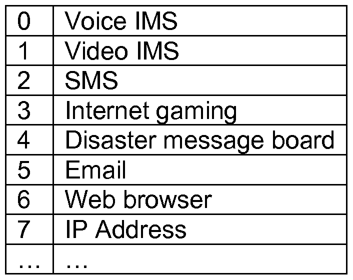
[0042] In embodiment (2) an application table can be used as shown in Table 2. An application filter like functionality is created to filter packets based on the application mapping table entries which can be pre-assigned to either MeNB or SeNB. In one embodiment, the mapping table entries are based on IP information (such as an IP address). The packet filters can determine whether to route packets to a MeNB or SeNB based on the IP address information.
[0043] In one embodiment, an application mapping table can provide functionality to filter data flow within the bearer (such as shown in Figure 5 in filter 506). An application mapping table can map an application entry to an IP address. For example, the application table contains different applications so that an IP to application mapping can be created at the setup. Table 2 is an example of the application table, but the number of applications and kind of applications should not be limited to what is shown.
Figure imgf000011_0001
Table 2 - Example Application Mapping Table
[0044] In another embodiment (3), current traffic flow templates (TFTs) can be extended to provide application dependent filtering. A TFT is used to define different types of application data paths using packet filters. For example, an extended TFT can filter port 80 for http traffic and send through a MeNB while other traffic is sent through a SeNB. Multiple configurations can be configured to a TFT. For example, a packet filter can be use the following contents:
00010000 IPv4 remote address type
00010001 IPv4 local address type
00100000 IPv6 remote address type
00100001 IPv6 remote address/prefix length type
00100011 IPv6 local address/prefix length type
00110000 Protocol identifier/Next header type
01000000 Single local port type
01000001 Local port range type
01010000 Single remote port type
01010001 Remote port range type
01100000 Security parameter index type
01110000 Type of service/Traffic class type
10000000 Flow label type
10000001 Macro cell or Small cell transmission preferred
All other values can be reserved
[0045] In another embodiment a traffic flow/packet filter can be associated to the preferred cell type. One way of implementing this association between the packet filter and the preferred cell type is to associate a QoS parameter field to each packet filter identifier. This can be accomplished by adding the QoS parameters field in the "packet filter list" e.g., [3GPP TS 24.008: Core network protocols; Stage 3], as shown in Table 3 below
Figure imgf000012_0001
Packet filter evaluation precedence N
Length of Packet filter contents N
Packet filter contents N
Preferred cell type N
Table 3 - Packet filter list when the TFT operation is "create new TFT", or "add packet filters to existing TFT" or "replace packet filters in existing TFT"
[0046] Optionally, this could be done by adding a list of s in the Traffic Flow Template
[3GPP TS 24.008: Core network protocols; Stage 3] as shown in Table 4below
Traffic flow template IEI
Length of traffic fl ow template IE
TFT operation E bit Number of packet
code filters
Packet filter list
Parameters list
Preferred cell type list
Table 4 - Traffic flow template information element
[0047] In another embodiment (4) multiple TFTs can be configured to a single bearer. For example, a set of packets may satisfy the criteria of two TFTs. However, a TFT that is more restrictive can be used to determine which packets are routed to a secondary link (such as a SeNB).
[0048] In a single connectivity environment, one evolved packet system (EPS) bearer maps to one TFT. With the extended TFTs in a dual connectivity environment, the network (such as a MeNB) can set two or more TFTs to map to a single bearer. Under a dual connectivity bearer split, each split bearer is associated with one of the TFTs.
[0049] For example, in Figure 6, TFT1 602 is divided into TFT2 604 and TFT3 606 (which can be written as TFT1 = TFT2+TFT3). As packets 612 and 614 flow through TFT1 602 arriving into the MeNB, a packet filter separates the flow into flows 608 and 610 based on application information (such as IP address or application table entry). Packets 612 having a first application characteristic are associated with TFT2 604 and routed through MeNB 616. Packets 614 having a second application characteristic are associated with TFT3 606 and routed through SeNB 618.
[0050] In another embodiment, when SeNB 618 is added by MeNB 616, a TFT is configured and applied to one or more bearers that MeNB 616 decides to offload to SeNB 618. This TFT is re-configured such that an application dependent packet is filtered and offloaded to SeNB 618. In Figure 6, for example, when SeNB 618 is added, MeNB 616 will configure TFT3 606 along with the bearer. The packet filters associated in TFT3 606 have to be a subset of TFT1 602. To do that, MeNB 616 can add, delete or modify packet filters in TFT. Similarly, MeNB 616 can modify the existing TFT2 604.
[0051] In another example of embodiment (4), an eNB can configure multiple TFTs for a single bearer when a SeNB is added. The eNB can follow the following operations: (1) when a single bearer (denoted Bl) is established, a TFT (denoted TFT1) is configured; (2) upon adding a SeNB, bearer Bl is split into two bearers (denoted B2 and B3) (B2 is a bearer that connects to MeNB and B3 is a bearer that connects to SeNB); (3) a new TFT (denoted TFT3) is configured to B3 and this new TFT is also automatically configured to Bl; and (4) when the SeNB is released, TFT3 is removed from Bl as well.
[0052] An example embodiment of a split bearer system 800 can be seen in Figure 8. An application server 810 creates three application specific data flows that include packets 814, 816 and 818. The application server 810 transmits the packets 814, 816 and 818 through S/P- GW 812 to macro cell 822. Macro cell 822 determines which packets are transmitted by the macro cell 822 to a UE and those packets are offloaded to small cell 824 for transmission to the UE.
[0053] Within application server 810, different application specific data flows are created. Application 1 (802) creates packets 816. Application 2 (804) creates packets 818.
Application 3 (806) creates packets 814. S/P-GW 812 receives these traffic flows and associates the flows with EPS bearers. Packets 814 form part of a first EPS bearer and a first traffic flow aggregate. Packets 816 and 818 form part of a second bearer and a corresponding second traffic flow aggregate.
[0054] One or more packet filters 820 receive these traffic flow aggregates at the macro cell 822 and route packets to a PDCP layer 826 or 834 (such as based on EPS bearer). Packets 814 are routed to PDCP layer 826 and are assigned a radio bearer. These packets 814 are then assigned a logical channel (dedicated traffic channel) in the RLC layer 828. The packets 814 then continue being processed through the MAC layer 830 (assigned a traffic channel - uplink shared channel (ULSCH)) and PHY layer 832 (assigned a physical channel - physical uplink shared channel (PUSCH)) for transmission to the UE.
[0055] Packets 816 are routed to PDCP layer 834 and are assigned a radio bearer. A packet filter within the PDCP layer 834 determines that packets 816 are to be transmitted by the macro cell 822 to the UE. These packets 816 are then assigned a logical channel (dedicated traffic channel) in the RLC layer 835. The packets 816 then continue being processed through the MAC layer 830 (assigned a traffic channel - ULSCH) and PHY layer 832 (assigned a physical channel - PUSCH) for transmission to the UE.
[0056] Packets 818 are routed to PDCP layer 834. A packet filter within the PDCP layer 834 determines that packets 816 are to be transmitted by the small cell 824 to the UE, resulting in a bearer split. The packets 818 are transmitted to small cell 824 to RLC layer 835 and are assigned a radio bearer. These packets 818 are then assigned a logical channel (dedicated traffic channel) in the RLC layer 835. The packets 816 then continue being processed through the MAC layer 838 (assigned a traffic channel - ULSCH) and PHY layer 840 (assigned a physical channel - PUSCH) for transmission to the UE.
[0057] In one example, a system 800 can be used to transfer data (such as video information) over a high speed link (that may not be as reliable as the macro cell 822 link) through the small cell 824, that may have a small coverage area. However, data corresponding to applications that need higher reliability (such as obtained through a larger coverage area but slower link speed) can be transferred over the macro cell 822 link.
[0058] An example embodiment of application dependent filtering system 900 can be seen in Figure 9. Application specific packets 922, 924 and 926 are generated from applications 902, 904 and 906 on UE 908. A packet filter 936 routes packets 922, 924 to a first wireless interface for transmission to SeNB 911 based on application specific attributes. The packet filter 936 routes packets 926 to a second wireless interface for transmission to MeNB 910. MeNB 910 and SeNB 911 transmit the packets 922, 924 and 926 to S/P-GW 912. S/P-GW 912 transmits traffic flows 962, 964 and 966 to service 914 that includes application 1 (916), application 2 (918) and application 3 (920).
[0059] As the packet filter 936 resides above PDCP layers 928 and 938, traffic flow aggregates can be formed by TFTs (a first TFT that includes packets 922 and 924 and a second TFT that includes packets 926). Packets 922 and 924 flow through PDCP layer 928 (becoming associated with a radio bearer) through RLC layer 930 (becoming associated with a logical channel (DTCH)) through MAC layer 932 (becoming associated with a transport channel (ULSCH)) and through the PHY layer 934 (becoming associated with a physical channel (PUSCH)) to be transmitted to MeNB 910. Packets 926 flow through a second protocol stack through PDCP layer 938 (becoming associated with a radio bearer) through RLC layer 940 (becoming associated with a logical channel (DTCH)) through MAC layer 942 (becoming associated with a transport channel (ULSCH)) and through the PHY layer 944 (becoming associated with a physical channel (PUSCH)) to be transmitted to SeNB 911. [0060] The packets 922, 924 and 926 are received by MeNB 910 and SeNB 911 and sent to S/P-GW 912, which can provide the packets to service 914 that includes application 1 (916), application 2 (918) and application 3 (920). A transmission from UE 908 to SeNB 911 based on packets 926 is routed through PHY layer 946 to MAC layer 948 to RLC layer 950 to PDCP layer 952 and then through an EPS bearer to S/P-GW 912 which routes packets 926 to application 920 (becoming traffic flow 962). A transmission from UE 908 to MeNB 910 based on packets 922 and 924 is routed through PHY layer 954 to MAC layer 956 to RLC layer 958 to PDCP layer 960 and then through an EPS bearer to S/P-GW 912 which routes packets 922 and 924 to applications 916 and 918 (becoming traffic flows 966 and 964).
[0061] For example, UE is running a GPS voice directions application. Current positioning information is reported by application 1 (902 on UE 908 and 916 on service 914). Voice directions are handled by application 2 (904 on UE 908 and 918 on service 914). A background map cache is provided by application 3 (906 on UE 908 and 920 on service 914). Positioning information (packets 924) and voice directions (packets 924) can be timing and reliability sensitive (as routes may need to be recalculated). However, a background map cache (packets 926) can be quickly loaded and stored for later use, allowing for high current data rates, but more unreliable connections if small updates are needed. MeNB 946 can determine that application 3 (906 on UE 908 and 920 on service 914) can make use of SeNB 911 and enables SeNB 911 for use (such as a request to turn on and/or accept connections from UE 908). MeNB 910 can then configure packet filters 936 or enable existing packet filters 936 (on both UE 908 and EPC, such as MeNB 910) to filter packets based on application based criteria (such as IP address, application of origin, etc.). Positioning information (packets 924) and voice directions (packets 922) are routed over a more robust (but potentially slower) link to MeNB 910 by packet filter 936. Background map cache (packets 926) are routed over a less robust (but potentially faster) link to SeNB 911 by packet filter 936.
[0062] In one embodiment (5), the packet filter also can be applied when the UE connects or dual connects to WLAN (e.g., Wi-Fi) networks. The eNB will configure the TFT and associated packet filters on the LTE bearer and WLAN link. For example, Figure 7 shows an example of dual connectivity of a UE 702 with an eNB 704 in using licensed spectrum (LTE 708) and a WLAN AP 706 using unlicensed spectrum (WLAN 710). Data from bearer SI 716 that is received from S-GW 714 can be split between eNB 704 and AP 706 based on application information (such as through a TFT, application table, QCI table, etc.). Internet access 718 can also be provided through a non-seamless WLAN offload (NSWO) link 720. In some embodiments the eNB 704 and AP 706 form a transmission unit 712. The eNB 704 and AP 706 share a link. The eNB 704 can offload traffic to the AP 706 using a packet filter based on application specific information (such as seen in Figure 4).
[0063] In some embodiments, the WLAN technology can be used instead of an SeNB (as seen in Figures 8 and 9). For example, extended TFTs (as discussed in embodiment 4) or multiple TFTs (as discussed in embodiment 5).
[0064] Figure 10 shows a method 1000 for application specific routing in dual connectivity. The method can be accomplished by systems such as those shown in Figure 1 , including anchor tower 104, small cell transceiver 106, UE 102, network infrastructure 118 (such as MME, etc.). In box 1002, a MeNB can receive downlink packets from the core network to transmit to a UE over a primary link (such as over licensed spectrum using LTE). In box 1004, MeNB (or in some cases MME or other part of EPC) determines to add a second link to the UE (which can be due to application specific demands). In box 1006, a packet filter is configured on UE and MeNB to select a route over the primary link or secondary link based on application information (such as IP address, application table, etc.). In some embodiments the packet filters are used in conjunction with TFTs. In box 1008, downlink packets are inspected by packet filters to determine whether to send the packets over the secondary link (such as a SeNB link, WLAN link, mm Wave link, etc.) or primary link. In box 1010, packets are routed to the selected link and transmitted to the UE.
[0065] In another embodiment, a UE can receive a message from a MeNB to connect to a SeNB. The UE can connect to the SeNB and enable a packet filter (which can be selected from pre-configured packet filters, received from the MeNB or other part of an EPC, or dynamically configured based on application information or demand information). Packets from the UE can be received by the packet filter and directed to a primary wireless interface (connected to the MeNB) or a secondary wireless interface (connected with the SeNB) based on application information. In some embodiments, this can result in a split radio bearer.
[0066] It should be recognized that a primary link and secondary link can be selected from various technologies and implementations. For example, a primary link can include protocols (LTE, LTE-U (LTE over unlicensed spectrum, which is sometimes referred to as licensed assisted access (LAA)), WLAN (also referred to as Wi-Fi™), mm Wave, etc.), spectrum (licensed spectrum, unlicensed spectrum, shared spectrum, etc.) and other technologies. A secondary link can include the same protocols, spectrum and technologies. For example, in some embodiments, a primary link can be WLAN over unlicensed spectrum and a secondary link can be mm Wave technology over licensed spectrum. Descriptions applied to a MeNB and SeNB can be applied to other wireless transceivers (such as a WLAN AP, mm Wave transceiver, etc.).
[0067] Figure 11 is an example illustration of a mobile device, such as a UE, a mobile station (MS), a mobile wireless device, a mobile communication device, a tablet, a handset, or another type of mobile wireless device. The mobile device can include one or more antennas configured to communicate with a transmission station, such as a base station (BS), an eNB, a base band unit (BBU), a remote radio head (R H), a remote radio equipment (RRE), a relay station (RS), a radio equipment (RE), or another type of wireless wide area network
(WW AN) access point. The mobile device can be configured to communicate using at least one wireless communication standard including 3GPP LTE, WiMAX, HSPA, Bluetooth, and Wi-Fi. The mobile device can communicate using separate antennas for each wireless communication standard or shared antennas for multiple wireless communication standards. The mobile device can communicate in a WLAN, a wireless personal area network (WPAN), and/or a WWAN.
[0068] Figure 11 also provides an illustration of a microphone and one or more speakers that can be used for audio input and output from the mobile device. The display screen can be a liquid crystal display (LCD) screen or other type of display screen, such as an organic light emitting diode (OLED) display. The display screen can be configured as a touch screen. The touch screen can use capacitive, resistive, or another type of touch screen technology. An application processor and a graphics processor can be coupled to internal memory to provide processing and display capabilities. A non- volatile memory port can also be used to provide data input/output options to a user. The non-volatile memory port can also be used to expand the memory capabilities of the mobile device. A keyboard can be integrated with the mobile device or wirelessly connected to the mobile device to provide additional user input. A virtual keyboard can also be provided using the touch screen.
[0069] Computing systems as discussed herein (such as UEs, eNBs, WLAN APs, systems that include processors, etc.) can be viewed as an information passing bus that connects various components. A computing system includes a processor having logic for processing instructions. Instructions can be stored in and/or retrieved from memory and a storage device that includes a computer-readable storage medium. Instructions and/or data can arrive from a network interface that can include wired or wireless capabilities. Instructions and/or data can also come from an I/O interface that can include such things as expansion cards, secondary buses (e.g., USB, etc.), devices, etc. A user can interact with the computing system through user interface devices and a rendering system that allows the computer to receive and provide feedback to the user.
[0070] Embodiments and implementations of the systems and methods described herein may include various operations, which may be embodied in machine-executable instructions to be executed by a computer system. A computer system may include one or more general- purpose or special-purpose computers (or other electronic devices). The computer system may include hardware components that include specific logic for performing the operations or may include a combination of hardware, software, and/or firmware.
[0071] Computer systems and the computers in a computer system may be connected via a network. Suitable networks for configuration and/or use as described herein include one or more local area networks, wide area networks, metropolitan area networks, and/or Internet or IP networks, such as the World Wide Web, a private Internet, a secure Internet, a value-added network, a virtual private network, an extranet, an intranet, or even stand-alone machines which communicate with other machines by physical transport of media. In particular, a suitable network may be formed from parts or entireties of two or more other networks, including networks using disparate hardware and network communication technologies.
[0072] One suitable network includes a server and one or more clients; other suitable networks may contain other combinations of servers, clients, and/or peer-to-peer nodes, and a given computer system may function both as a client and as a server. Each network includes at least two computers or computer systems, such as the server and/or clients. A computer system may include a workstation, laptop computer, disconnectable mobile computer, server, mainframe, cluster, so-called "network computer" or "thin client," tablet, smart phone, personal digital assistant or other hand-held computing device, "smart" consumer electronics device or appliance, medical device, or a combination thereof.
[0073] Suitable networks may include communications or networking software, such as the software available from Novell®, Microsoft®, and other vendors, and may operate using TCP/IP, SPX, IPX, and other protocols over twisted pair, coaxial, or optical fiber cables, telephone lines, radio waves, satellites, microwave relays, modulated AC power lines, physical media transfer, and/or other data transmission "wires" known to those of skill in the art. The network may encompass smaller networks and/or be connectable to other networks through a gateway or similar mechanism.
[0074] Various techniques, or certain aspects or portions thereof, may take the form of program code (i.e., instructions) embodied in tangible media, such as floppy diskettes, CD- ROMs, hard drives, magnetic or optical cards, solid-state memory devices, a nontransitory computer-readable storage medium, or any other machine-readable storage medium wherein, when the program code is loaded into and executed by a machine, such as a computer, the machine becomes an apparatus for practicing the various techniques. In the case of program code execution on programmable computers, the computing device may include a processor, a storage medium readable by the processor (including volatile and nonvolatile memory and/or storage elements), at least one input device, and at least one output device. The volatile and nonvolatile memory and/or storage elements may be a RAM, an EPROM, a flash drive, an optical drive, a magnetic hard drive, or other medium for storing electronic data. The eNB (or other base station) and UE (or other mobile station) may also include a transceiver component, a counter component, a processing component, and/or a clock component or timer component. One or more programs that may implement or utilize the various techniques described herein may use an application programming interface (API), reusable controls, and the like. Such programs may be implemented in a high-level procedural or an object-oriented programming language to communicate with a computer system. However, the program(s) may be implemented in assembly or machine language, if desired. In any case, the language may be a compiled or interpreted language, and combined with hardware implementations.
[0075] Each computer system includes one or more processors and/or memory; computer systems may also include various input devices and/or output devices. The processor may include a general purpose device, such as an Intel®, AMD®, or other "off-the-shelf microprocessor. The processor may include a special purpose processing device, such as ASIC, SoC, SiP, FPGA, PAL, PLA, FPLA, PLD, or other customized or programmable device. The memory may include static RAM, dynamic RAM, flash memory, one or more flip-flops, ROM, CD-ROM, DVD, disk, tape, or magnetic, optical, or other computer storage medium. The input device(s) may include a keyboard, mouse, touch screen, light pen, tablet, microphone, sensor, or other hardware with accompanying firmware and/or software. The output device(s) may include a monitor or other display, printer, speech or text synthesizer, switch, signal line, or other hardware with accompanying firmware and/or software.
[0076] It should be understood that many of the functional units described in this
specification may be implemented as one or more components, which is a term used to more particularly emphasize their implementation independence. For example, a component may be implemented as a hardware circuit comprising custom very large scale integration (VLSI) circuits or gate arrays, or off-the-shelf semiconductors such as logic chips, transistors, or other discrete components. A component may also be implemented in programmable hardware devices such as field programmable gate arrays, programmable array logic, programmable logic devices, or the like.
[0077] Components may also be implemented in software for execution by various types of processors. An identified component of executable code may, for instance, comprise one or more physical or logical blocks of computer instructions, which may, for instance, be organized as an object, a procedure, or a function. Nevertheless, the executables of an identified component need not be physically located together, but may comprise disparate instructions stored in different locations that, when joined logically together, comprise the component and achieve the stated purpose for the component.
[0078] Indeed, a component of executable code may be a single instruction, or many instructions, and may even be distributed over several different code segments, among different programs, and across several memory devices. Similarly, operational data may be identified and illustrated herein within components, and may be embodied in any suitable form and organized within any suitable type of data structure. The operational data may be collected as a single data set, or may be distributed over different locations including over different storage devices, and may exist, at least partially, merely as electronic signals on a system or network. The components may be passive or active, including agents operable to perform desired functions.
[0079] Several aspects of the embodiments described will be illustrated as software modules or components. As used herein, a software module or component may include any type of computer instruction or computer-executable code located within a memory device. A software module may, for instance, include one or more physical or logical blocks of computer instructions, which may be organized as a routine, program, object, component, data structure, etc., that perform one or more tasks or implement particular data types. It is appreciated that a software module may be implemented in hardware and/or firmware instead of or in addition to software. One or more of the functional modules described herein may be separated into sub-modules and/or combined into a single or smaller number of modules.
[0080] In certain embodiments, a particular software module may include disparate instructions stored in different locations of a memory device, different memory devices, or different computers, which together implement the described functionality of the module. Indeed, a module may include a single instruction or many instructions, and may be distributed over several different code segments, among different programs, and across several memory devices. Some embodiments may be practiced in a distributed computing environment where tasks are performed by a remote processing device linked through a communications network. In a distributed computing environment, software modules may be located in local and/or remote memory storage devices. In addition, data being tied or rendered together in a database record may be resident in the same memory device, or across several memory devices, and may be linked together in fields of a record in a database across a network.
[0081] Reference throughout this specification to "an example" means that a particular feature, structure, or characteristic described in connection with the example is included in at least one embodiment of the present invention. Thus, appearances of the phrase "in an example" in various places throughout this specification are not necessarily all referring to the same embodiment.
[0082] As used herein, a plurality of items, structural elements, compositional elements, and/or materials may be presented in a common list for convenience. However, these lists should be construed as though each member of the list is individually identified as a separate and unique member. Thus, no individual member of such list should be construed as a de facto equivalent of any other member of the same list solely based on its presentation in a common group without indications to the contrary. In addition, various embodiments and examples of the present invention may be referred to herein along with alternatives for the various components thereof. It is understood that such embodiments, examples, and alternatives are not to be construed as de facto equivalents of one another, but are to be considered as separate and autonomous representations of the present invention.
[0083] Furthermore, the described features, structures, or characteristics may be combined in any suitable manner in one or more embodiments. In the above description, numerous specific details are provided, such as examples of materials, frequencies, sizes, lengths, widths, shapes, etc., to provide a thorough understanding of embodiments of the invention. One skilled in the relevant art will recognize, however, that the invention may be practiced without one or more of the specific details, or with other methods, components, materials, etc. In other instances, well-known structures, materials, or operations are not shown or described in detail to avoid obscuring aspects of the invention.
[0084] Although the foregoing has been described in some detail for purposes of clarity, it will be apparent that certain changes and modifications may be made without departing from the principles thereof. It should be noted that there are many alternative ways of
implementing both the processes and apparatuses described herein. Accordingly, the present embodiments are to be considered illustrative and not restrictive, and the invention is not to be limited to the details given herein, but may be modified within the scope and equivalents of the appended claims.
[0085] Those having skill in the art will appreciate that many changes may be made to the details of the above-described embodiments without departing from the underlying principles of the invention. The scope of the present invention should, therefore, be determined only by the following claims.
Examples
[0086] The following examples pertain to further embodiments.
[0087] Example 1 is a A user equipment (UE) for having dual connectivity that includes a processor, transceiver system and packet filter. The processor is configured to execute one or more applications that generate network traffic comprising packets for transmission from the UE. The transceiver system is configured to communicate the packets over at least two wireless channels. The packet filter is configured to inspect a packet from the network traffic generated from the one or more applications and select a route for transmission of the packet over one of the at least two wireless channels based at least in part on its association with an application from the one or more applications..
[0088] In Example 2, the UE of Example 1 can optionally have a first channel of the at least two wireless channels comprise a licensed set of frequencies.
[0089] In Example 3, UE of Example 2 can optionally have a second channel of the at least two channels comprise a wireless local area network (WLAN).
[0090] In Example 4, the UE in Examples 1-3 can optionally include a packet filter configuration that is selected from a set of preconfigured packet filter configurations.
[0091] In Example 5, the UE Examples 1-4 can optionally have the packet filter route packets from the packet data convergence protocol (PDCP) layer.
[0092] Example 6, is a system for dual connectivity including a gateway, a primary enhanced node B (eNB) and a secondary eNB. The gateway is configured to communicate packets associated with an evolved packet system (EPS) bearer with a destination of user equipment (UE). The primary enhanced node B (eNB) includes a packet splitter configured to split the EPS bearer into at least two streams of packets. A first stream is communicated over a first set of wireless frequencies from the primary eNB to the UE. A second stream is routed through a secondary eNB. The secondary eNB is configured to communicate the second stream over a second set of wireless frequencies to the UE. [0093] In Example 7, the system of Example 6 can optionally configure a packet splitter to use a quality of service class identifier (QCI) table to determine the first stream and the second stream.
[0094] In Example 8, the system of Example 6 can optionally configure the packet splitter to use an application mapping table to determine the first stream and the second stream.
[0095] In Example 9, the system of Example 6 can optionally configure the primary eNB to map at least two traffic flow templates (TFTs) to a single bearer. The packet splitter can also be further configured to assign the packets to the first stream or the second stream based at least in part on the at least two TFTs.
[0096] In Example 10, the system of Examples 6-9 can optionally be configured to have the secondary eNB communicate over unlicensed frequencies.
[0097] In Example 11, the system of Examples 6-10 can optionally configure the primary eNB to map a second more restrictive traffic flow template (TFT) to a single bearer that has a first TFT. The packet splitter can also be further configured to route at least a portion of the packets to the second stream based at least in part on the packets matching the second TFT.
[0098] Example 12 is a method of application specific routing. The method includes connecting a third generation partnership project (3 GPP) compatible primary wireless link to user equipment (UE). The method also includes receiving a downlink packet from a core network. The method includes determining to add a secondary wireless link to user equipment (UE). The method also includes enabling a packet splitter to determine allocation of packets between the primary wireless link and the secondary wireless link. The method includes inspecting the downlink packet to determine an association with an application. The method also includes determining whether to send the downlink packet to the UE over the primary wireless link or the secondary wireless link based at least in part on the association.
[0099] In Example 13, the method of Example 12 can optionally include splitting a radio bearer between the primary wireless link and the secondary wireless link based at least in part on the association of packets within the radio bearer with an application.
[0100] In Example 14, the method of Examples 12-13 can optionally establishing a first bearer and an associated first traffic flow template (TFT) configured to transmit over the primary wireless link. The method can include splitting the first bearer into a second bearer and a third bearer. The method can also include associating the second bearer with the primary wireless link. The method can include associating the third bearer with the secondary wireless link. The method can also include configuring a third TFT to associate with the third bearer and the first bearer. [0101] In Example 15, the method of Example 12-14 can optionally include mapping two or more traffic flow templates (TFT) to a single bearer.
[0102] In Example 16, the method of Examples 12-15 can optionally include inspecting the downlink packet to determine the association with an application further comprises determining a quality of service class indicator (QCI) value assigned to an application.
[0103] Example 17 is user equipment (UE) for communicating in a dual connectivity environment that includes a first wireless interface, a second wireless interface and a processor. The first wireless interface is configured to communicate over a licensed set of frequencies using a radio bearer. The second wireless interface is configured to communicate over a second set of frequencies. The processor is configured to receive a set of uplink packets belonging to a bearer. The processor is additionally configured to determine allocation of the set of uplink packets between the first wireless interface and the second wireless interface based at least in part on the uplink packets association with an application The processor is also configured to cause a first subset of the uplink packets to be sent over the first wireless interface based at least in part on the determined allocation. The processor can also be configured to cause a second subset of the uplink packets to be sent over the second wireless interface based at least in part on the determined allocation.
[0104] In Example 18, the UE of Example 17 can optionally perform allocation of the packets to the first wireless interface based on a determination that the first wireless interface has a higher reliability than the second wireless interface.
[0105] In Example 19, the UE of Examples 17-18 can optionally perform allocation of the packets to the second wireless interface based on a determination that the second wireless interface has a higher throughput than the first wireless interface.
[0106] In Example 20, the UE of Examples 17- 19 can optionally include configuring the processor for receiving a configuration over the first wireless interface for determining the allocation of the uplink packets, the configuration associating an application with the first wireless interface or the second wireless interface.

Claims

Claims: What is claimed is:
1. A user equipment (UE) for having dual connectivity comprising:
a processor configured to execute one or more applications that generate network traffic comprising packets for transmission from the UE;
a transceiver system configured to communicate the packets over at least two wireless channels, the at least two wireless channels including a primary link and a secondary link; a packet filter configured to inspect a packet from the network traffic generated from the one or more applications and select a route for transmission of the packet over one of the at least two wireless channels based at least in part on its association with an application from the one or more applications.
2. The UE of claim 1, wherein a first channel of the at least two wireless channels comprises a licensed set of frequencies.
3. The UE of claim 2, wherein a second channel of the at least two wireless channels comprises a wireless local area network (WLAN).
4. The UE of claim 1, wherein a packet filter configuration is selected from a set of preconfigured packet filter configurations.
5. The UE of claim 1, wherein the packet filter routes packets from the packet data convergence protocol (PDCP) layer.
6. A system for dual connectivity comprising:
a gateway configured to communicate packets associated with an evolved packet system (EPS) bearer with a destination of user equipment (UE);
a primary enhanced node B (eNB) comprising:
a packet splitter configured to split the EPS bearer into at least two streams of packets, a first stream being communicated over a first set of wireless frequencies from the primary eNB to the UE, a second stream being routed through a secondary eNB; and
the secondary eNB configured to communicate the second stream over a second set of wireless frequencies to the UE.
7. The system of claim 6, wherein the packet splitter is further configured to use a quality of service class identifier (QCI) table to determine the first stream and the second stream.
8. The system of claim 6, wherein the packet splitter is further configured to use an application mapping table to determine the first stream and the second stream.
9. The system of claim 6, wherein the packet splitter is further configured to:
use a quality of service class identifier (QCI) table to determine the first stream and the second stream; or
use an application mapping table to determine the first stream and the second stream.
10. The system of claim 6, wherein the primary eNB is configured to map at least two traffic flow templates (TFTs) to a single bearer; and
wherein the packet splitter is further configured to assign the packets to the first stream or the second stream based at least in part on the at least two TFTs.
11. The system of claim 6, wherein the secondary eNB is configured to communicate over unlicensed frequencies.
12. The system of claim 6, wherein the primary eNB is configured to map a more restrictive second traffic flow template (TFT) to a single bearer that has a first TFT; and wherein the packet splitter is further configured to route at least a portion of the packets to the second stream based at least in part on the packets matching the second TFT.
13. A method of application specific routing comprising:
connecting a third generation partnership project (3 GPP) compatible primary wireless link to user equipment (UE);
receiving a downlink packet from a core network;
determining to add a secondary wireless link to the UE;
enabling a packet splitter to determine allocation of packets between the primary wireless link and the secondary wireless link;
inspecting the downlink packet to determine an association with an application; and determining whether to send the downlink packet to the UE over the primary wireless link or the secondary wireless link based at least in part on the association.
14. The method of claim 13, further comprising splitting a radio bearer between the primary wireless link and the secondary wireless link based at least in part on the association of packets within the radio bearer with the application.
15. The method of claim 13, further comprising:
establishing a first bearer and an associated first traffic flow template (TFT) configured to transmit over the primary wireless link;
splitting the first bearer into a second bearer and a third bearer;
associating the second bearer with the primary wireless link;
associating the third bearer with the secondary wireless link; and
configuring a third TFT to associate with the third bearer and the first bearer.
16. The method of claim 13, further comprising mapping two or more traffic flow templates (TFT) to a single bearer.
17. The method of claim 13, wherein inspecting the downlink packet to determine the association with the application further comprises determining a quality of service class indicator (QCI) value assigned to the application.
18. The method of claim 13, further comprising one or more of:
mapping two or more traffic flow templates (TFT) to a single bearer;
splitting a radio bearer between the primary wireless link and the secondary wireless link based at least in part on the association of packets within the radio bearer with the application; or
establishing a first bearer and an associated first traffic flow template (TFT) configured to transmit over the primary wireless link, splitting the first bearer into a second bearer and a third bearer, associating the second bearer with the primary wireless link, associating the third bearer with the secondary wireless link, and configuring a third TFT to associate with the third bearer and the first bearer.
19. An apparatus comprising means to perform a method as claimed in any of claims
13-18.
20. Machine readable storage including machine-readable instructions that when executed implement a method or realize an apparatus as claimed in any of claims 13-18.
21. User equipment (UE) for communicating in a dual connectivity environment comprising:
a first wireless interface configured to communicate over a licensed set of frequencies using a radio bearer;
a second wireless interface configured to communicate over a second set of frequencies; and
a processor configured to:
receive a set of uplink packets belonging to a bearer;
determine allocation of the set of uplink packets between the first wireless interface and the second wireless interface based at least in part on an association of the uplink packets with an application;
cause a first subset of the set of the uplink packets to be sent over the first wireless interface based at least in part on the determined allocation; and
cause a second subset of the set of the uplink packets to be sent over the second wireless interface based at least in part on the determined allocation.
22. The UE of claim 21, wherein the allocation of the first subset of the set of uplink packets to the first wireless interface is based on a determination that the first wireless interface has a higher reliability than the second wireless interface.
23. The UE of claim 21, wherein the allocation of the second subset of the set of uplink packets to the second wireless interface is based on a determination that the second wireless interface has a higher throughput than the first wireless interface.
24. The UE of claim 21, wherein the processor is further configured to receive a configuration over the first wireless interface for determining the allocation of the set of uplink packets, the configuration associating the application with the first wireless interface or the second wireless interface.
PCT/US2015/011427 2014-01-30 2015-01-14 Systems, methods and devices for application specific routing in dual connectivity WO2015116387A1 (en)

Priority Applications (3)

Application Number Priority Date Filing Date Title
JP2016561997A JP6342514B2 (en) 2014-01-30 2015-01-14 System, method and device for application specific routing in a dual connection
CN201580003239.7A CN106063330B (en) 2014-01-30 2015-01-14 System, method and apparatus for application specific routing in dual connectivity
EP15743766.6A EP3100517B8 (en) 2014-01-30 2015-01-14 Systems, devices and computer-readable medium for application specific routing in dual connectivity

Applications Claiming Priority (4)

Application Number Priority Date Filing Date Title
US201461933865P 2014-01-30 2014-01-30
US61/933,865 2014-01-30
US14/580,797 2014-12-23
US14/580,797 US20150215840A1 (en) 2014-01-30 2014-12-23 Systems, methods and devices for application specific routing in dual connectivity

Publications (1)

Publication Number Publication Date
WO2015116387A1 true WO2015116387A1 (en) 2015-08-06

Family

ID=53680406

Family Applications (1)

Application Number Title Priority Date Filing Date
PCT/US2015/011427 WO2015116387A1 (en) 2014-01-30 2015-01-14 Systems, methods and devices for application specific routing in dual connectivity

Country Status (6)

Country Link
US (1) US20150215840A1 (en)
EP (1) EP3100517B8 (en)
JP (1) JP6342514B2 (en)
CN (1) CN106063330B (en)
TW (1) TWI552622B (en)
WO (1) WO2015116387A1 (en)

Cited By (4)

* Cited by examiner, † Cited by third party
Publication number Priority date Publication date Assignee Title
WO2017071295A1 (en) * 2015-10-30 2017-05-04 中兴通讯股份有限公司 Unlicensed carrier resource processing method and device
JPWO2017038563A1 (en) * 2015-08-31 2018-08-30 株式会社Nttドコモ User terminal, radio base station, and radio communication method
JP2019503606A (en) * 2015-11-27 2019-02-07 華為技術有限公司Huawei Technologies Co.,Ltd. Network node, wireless communication system, and method thereof
JPWO2018003480A1 (en) * 2016-06-30 2019-04-18 株式会社Nttドコモ Communication control apparatus, user apparatus and communication control method

Families Citing this family (26)

* Cited by examiner, † Cited by third party
Publication number Priority date Publication date Assignee Title
US9843518B2 (en) 2014-03-14 2017-12-12 International Business Machines Corporation Remotely controlled message queue
US10542452B2 (en) * 2014-06-10 2020-01-21 Apple Inc. Enhancing quality of service for high priority services
US10999882B2 (en) * 2014-09-05 2021-05-04 Telefonaktiebolaget Lm Ericsson (Publ) Multipath control of data streams
WO2018211488A1 (en) 2017-05-18 2018-11-22 Liveu Ltd. Device, system, and method of wireless multiple-link vehicular communication
US10631287B2 (en) * 2014-09-26 2020-04-21 Samsung Electronics Co., Ltd. Method and apparatus for supporting multi-radio access technology
US20180123752A1 (en) * 2015-04-20 2018-05-03 Nokia Solutions And Networks Oy Method and apparatus for handling data activity of a secondary cell
US11178558B2 (en) * 2015-05-22 2021-11-16 Parallel Wireless, Inc. Wireless backhaul resiliency
CN107079520A (en) * 2015-08-14 2017-08-18 华为技术有限公司 Data transmission method and base station of the base station in frequency spectrum auxiliary access cell is authorized
WO2017078743A1 (en) * 2015-11-03 2017-05-11 Intel IP Corporation Devices and methods of drx and wlan power saving mode synchronization for lwa
CN114363948A (en) * 2015-11-06 2022-04-15 IPCom两合公司 Enhancement of MDT services
US20170230871A1 (en) * 2016-02-04 2017-08-10 Sooktha Consulting Private Limited Cellular Wireless Access Data Offload System
TWI669933B (en) * 2016-02-17 2019-08-21 財團法人資訊工業策進會 System for controlling terminal equipment, gateway and method of adding new terminal equipment
US10517021B2 (en) 2016-06-30 2019-12-24 Evolve Cellular Inc. Long term evolution-primary WiFi (LTE-PW)
EP3461216B1 (en) 2016-06-30 2023-12-13 Huawei Technologies Co., Ltd. Multi-connection communication method and device
EP3902368B1 (en) * 2016-09-30 2023-05-03 Samsung Electronics Co., Ltd. Method and apparatus for establishing dual-connectivity to transmit data in new radio communication architecture
ES2946703T3 (en) 2016-09-30 2023-07-24 Samsung Electronics Co Ltd Method and apparatus for establishing double connectivity to transmit data in a new radio communication architecture
US10512115B2 (en) 2016-12-08 2019-12-17 Htc Corporation Device and method of handling data transmission
US10237784B2 (en) * 2017-03-24 2019-03-19 Motorola Mobility Llc Split bearer packet data converge protocol protocol data unit routing
CN114245435A (en) * 2017-06-16 2022-03-25 中兴通讯股份有限公司 Second path configuration
WO2019094770A1 (en) * 2017-11-09 2019-05-16 Google Llc Enabling concurrent use of multiple cellular network technologies
CN108471633B (en) * 2018-03-07 2020-12-04 北京佰才邦技术有限公司 Communication method and communication system
US11658208B2 (en) * 2018-03-20 2023-05-23 Intel Corporation Thin film transistors for high voltage applications
CN110536477B (en) * 2019-04-03 2023-11-14 中兴通讯股份有限公司 Connection method, device, network equipment and storage medium
US11025520B2 (en) * 2019-06-28 2021-06-01 Intel Corporation Quality-of-service in cellular information centric network
TWI762814B (en) 2019-09-03 2022-05-01 中磊電子股份有限公司 Base station and adjusting method of data transmission
US11683737B1 (en) * 2021-04-22 2023-06-20 T-Mobile Innovations Llc mmWave to Wi-Fi control signal offloading in the event of fading in the mmWave system

Citations (3)

* Cited by examiner, † Cited by third party
Publication number Priority date Publication date Assignee Title
US20100034083A1 (en) * 2008-08-08 2010-02-11 Qualcomm Incorporated Method and apparatus for packet differentiation in a wireless communication system
US8351327B1 (en) * 2006-08-28 2013-01-08 Juniper Networks, Inc. Intermediate network device applying application-layer quality of service to channels within a communication session
US20130322347A1 (en) 2012-05-31 2013-12-05 Cisco Technology, Inc. Leveraging multiple access technologies simultaneously

Family Cites Families (18)

* Cited by examiner, † Cited by third party
Publication number Priority date Publication date Assignee Title
JP2005539421A (en) * 2002-09-11 2005-12-22 ドコモ コミュニケーションズ ラボラトリーズ ヨーロッパ ゲーエムベーハー Middleware platform
KR100886551B1 (en) * 2003-02-21 2009-03-02 삼성전자주식회사 Apparatus for traffic flow template packet filtering according to internet protocol version in mobile communication system and method thereof
KR100691505B1 (en) * 2005-05-20 2007-03-09 한국전자통신연구원 Multi-mode user equipment and routing controlling method thereby
ATE550906T1 (en) * 2006-05-05 2012-04-15 Ericsson Telefon Ab L M METHOD AND SYSTEM FOR DYNAMIC CONFIGURING A TRAFFIC FLOW TEMPLATE
CN102067669A (en) * 2008-06-16 2011-05-18 三星电子株式会社 Method and system for managing handover in radio access networks
JP5204855B2 (en) * 2008-12-26 2013-06-05 シャープ株式会社 Control station, mobile station and mobile communication system
US8867486B2 (en) * 2009-04-17 2014-10-21 Qualcomm Incorporated Wireless data communications employing IP flow mobility
CN102014372B (en) * 2010-11-30 2014-11-05 中兴通讯股份有限公司 Method, device and system for controlling service data traffic distribution
JP5977251B2 (en) * 2010-12-03 2016-08-24 インターデイジタル パテント ホールディングス インコーポレイテッド Method, apparatus and system for performing multi-radio access technology carrier aggregation
CN102761904B (en) * 2011-04-28 2017-10-10 中兴通讯股份有限公司 Data transmission method, equipment and system
WO2011157129A2 (en) * 2011-05-31 2011-12-22 华为技术有限公司 Data transmission method, stream distribution node device, user equipment and system
US9490948B2 (en) * 2011-06-20 2016-11-08 Vid Scale, Inc. Method and apparatus for video aware bandwidth aggregation and/or management
WO2013037137A1 (en) * 2011-09-16 2013-03-21 Nec (China) Co., Ltd. Method and apparatus for determining transmission power of a secondary transmitter in a hierarchical specturm sharing system
US9877139B2 (en) * 2011-10-03 2018-01-23 Intel Corporation Device to device (D2D) communication mechanisms
US9883441B2 (en) * 2011-11-10 2018-01-30 Nokia Technologies Oy Method and apparatus to route packet flows over two transport radios
US20130150032A1 (en) * 2011-12-12 2013-06-13 Broadcom Corporation Controlled Idle Mode Behavior in User Equipment Supporting Multiple Radio Access Techniques
CN103582011A (en) * 2012-07-26 2014-02-12 中兴通讯股份有限公司 System and method for conducting multi-network combination transmission and user equipment
EP3061308A2 (en) * 2013-10-22 2016-08-31 Alcatel Lucent Integration of cellular and wlan systems

Patent Citations (3)

* Cited by examiner, † Cited by third party
Publication number Priority date Publication date Assignee Title
US8351327B1 (en) * 2006-08-28 2013-01-08 Juniper Networks, Inc. Intermediate network device applying application-layer quality of service to channels within a communication session
US20100034083A1 (en) * 2008-08-08 2010-02-11 Qualcomm Incorporated Method and apparatus for packet differentiation in a wireless communication system
US20130322347A1 (en) 2012-05-31 2013-12-05 Cisco Technology, Inc. Leveraging multiple access technologies simultaneously

Non-Patent Citations (5)

* Cited by examiner, † Cited by third party
Title
"Data split options and considerations on U-plane protocol architecture for dual-connectivity", 3GPP TSG-RAN WG2 MEETING #81BIS, April 2013 (2013-04-01)
"Impacts of Splitting a Single EPS Bearer between Two (or more) eNBs", 3GPP TSG-RAN WG2 MEETING #81BIS, April 2013 (2013-04-01)
INTEL CORPORATION: "Impacts of Splitting a Single EPS Bearer between Two (or more) eNBs", R2-131401, 3GPP TSG RAN WG2 MEETING #81BIS, 15 April 2013 (2013-04-15), CHICAGO, USA, XP050699523, Retrieved from the Internet <URL:http://www.3gpp.org/ftp/tsg_ran/wg2_r12/TSGR2_81bis/Docs> *
NOKIA CORPORATION ET AL.: "Discussion on small cells dual connectivity", R2-130453, 3GPP TSG-RAN WG2 MEETING #81, 28 January 2013 (2013-01-28), MALTA, XP050668368, Retrieved from the Internet <URL:http://www.3gpp.org/ftp/tsg_ran/wg2_r12/TSGR2_81/Docs> *
NOKIA SIEMENS NETWORKS ET AL.: "Data split options and considerations on U-plane protocol architecture for dual-connectivity", R2-131054, 3GPP TSG-RAN WG2 MEETING #81BIS, 15 April 2013 (2013-04-15), CHICAGO, USA, XP050699230, Retrieved from the Internet <URL:http://www.3gpp.org/ftp/tsg-ran/wg2_212/TSGR2-81bis/Docs> *

Cited By (8)

* Cited by examiner, † Cited by third party
Publication number Priority date Publication date Assignee Title
JPWO2017038563A1 (en) * 2015-08-31 2018-08-30 株式会社Nttドコモ User terminal, radio base station, and radio communication method
US10841935B2 (en) 2015-08-31 2020-11-17 Ntt Docomo, Inc. User terminal, radio base station and radio communication method
WO2017071295A1 (en) * 2015-10-30 2017-05-04 中兴通讯股份有限公司 Unlicensed carrier resource processing method and device
CN106658721A (en) * 2015-10-30 2017-05-10 中兴通讯股份有限公司 Unauthorized carrier resource processing method and device
CN106658721B (en) * 2015-10-30 2020-05-19 中兴通讯股份有限公司 Unauthorized carrier resource processing method and device
JP2019503606A (en) * 2015-11-27 2019-02-07 華為技術有限公司Huawei Technologies Co.,Ltd. Network node, wireless communication system, and method thereof
US10659994B2 (en) 2015-11-27 2020-05-19 Huawei Technologies Co., Ltd. Network nodes, wireless communication system and methods thereof
JPWO2018003480A1 (en) * 2016-06-30 2019-04-18 株式会社Nttドコモ Communication control apparatus, user apparatus and communication control method

Also Published As

Publication number Publication date
EP3100517B8 (en) 2021-02-24
TWI552622B (en) 2016-10-01
TW201543922A (en) 2015-11-16
CN106063330B (en) 2020-06-26
JP6342514B2 (en) 2018-06-13
US20150215840A1 (en) 2015-07-30
EP3100517A4 (en) 2017-10-04
CN106063330A (en) 2016-10-26
EP3100517B1 (en) 2020-10-21
JP2017512034A (en) 2017-04-27
EP3100517A1 (en) 2016-12-07

Similar Documents

Publication Publication Date Title
EP3100517B1 (en) Systems, devices and computer-readable medium for application specific routing in dual connectivity
TWI600297B (en) Systems, methods, and apparatuses for bearer splitting in multi-radio hetnet
JP6415603B2 (en) Apparatus and method for improving quality of service architecture for LTE
CN105557018B (en) The end-to-end tunnel (E2E) for multi radio access technology (more RAT)
CN109565729B (en) End-tag handling for mobility between 5G and LTE
JP6365740B2 (en) Wireless communication system, mobile station, wireless station, and communication method
US20190075482A1 (en) Reflective mapping of flows to radio bearers
US20160037428A1 (en) Methods and devices for providing application services to users in communications network
US9432873B2 (en) Differentiation of traffic flows for uplink transmission
KR20160083928A (en) Unification sublayer for multi-connection communication
KR20210021059A (en) Realization of quality of service in multi-hop data delivery
GB2551485A (en) Providing service data flow description
US20150092540A1 (en) System and Method for Traffic Offload
US20180063295A1 (en) Position-based communication routing
US20150223107A1 (en) User equipment and method for application specific packet filter
US20220330083A1 (en) Methods and apparatuses for transmitting and receiving data in an nr system
WO2018031081A1 (en) Systems and methods for packet data convergence protocol sequencing
US10499274B2 (en) Establishing an interaction session between a service client and a RAN
US11751055B2 (en) User plane integrity protection in cellular networks

Legal Events

Date Code Title Description
121 Ep: the epo has been informed by wipo that ep was designated in this application

Ref document number: 15743766

Country of ref document: EP

Kind code of ref document: A1

REEP Request for entry into the european phase

Ref document number: 2015743766

Country of ref document: EP

WWE Wipo information: entry into national phase

Ref document number: 2015743766

Country of ref document: EP

ENP Entry into the national phase

Ref document number: 2016561997

Country of ref document: JP

Kind code of ref document: A

NENP Non-entry into the national phase

Ref country code: DE