WO2015115106A1 - Hydraulic hammering device - Google Patents
Hydraulic hammering device Download PDFInfo
- Publication number
- WO2015115106A1 WO2015115106A1 PCT/JP2015/000409 JP2015000409W WO2015115106A1 WO 2015115106 A1 WO2015115106 A1 WO 2015115106A1 JP 2015000409 W JP2015000409 W JP 2015000409W WO 2015115106 A1 WO2015115106 A1 WO 2015115106A1
- Authority
- WO
- WIPO (PCT)
- Prior art keywords
- chamber
- liner
- front chamber
- piston
- hydraulic
- Prior art date
Links
Images


Classifications
-
- B—PERFORMING OPERATIONS; TRANSPORTING
- B25—HAND TOOLS; PORTABLE POWER-DRIVEN TOOLS; MANIPULATORS
- B25D—PERCUSSIVE TOOLS
- B25D9/00—Portable percussive tools with fluid-pressure drive, i.e. driven directly by fluids, e.g. having several percussive tool bits operated simultaneously
- B25D9/14—Control devices for the reciprocating piston
- B25D9/16—Valve arrangements therefor
- B25D9/20—Valve arrangements therefor involving a tubular-type slide valve
-
- B—PERFORMING OPERATIONS; TRANSPORTING
- B25—HAND TOOLS; PORTABLE POWER-DRIVEN TOOLS; MANIPULATORS
- B25D—PERCUSSIVE TOOLS
- B25D9/00—Portable percussive tools with fluid-pressure drive, i.e. driven directly by fluids, e.g. having several percussive tool bits operated simultaneously
- B25D9/04—Portable percussive tools with fluid-pressure drive, i.e. driven directly by fluids, e.g. having several percussive tool bits operated simultaneously of the hammer piston type, i.e. in which the tool bit or anvil is hit by an impulse member
-
- B—PERFORMING OPERATIONS; TRANSPORTING
- B25—HAND TOOLS; PORTABLE POWER-DRIVEN TOOLS; MANIPULATORS
- B25D—PERCUSSIVE TOOLS
- B25D9/00—Portable percussive tools with fluid-pressure drive, i.e. driven directly by fluids, e.g. having several percussive tool bits operated simultaneously
- B25D9/06—Means for driving the impulse member
- B25D9/12—Means for driving the impulse member comprising a built-in liquid motor, i.e. the tool being driven by hydraulic pressure
-
- B—PERFORMING OPERATIONS; TRANSPORTING
- B25—HAND TOOLS; PORTABLE POWER-DRIVEN TOOLS; MANIPULATORS
- B25D—PERCUSSIVE TOOLS
- B25D9/00—Portable percussive tools with fluid-pressure drive, i.e. driven directly by fluids, e.g. having several percussive tool bits operated simultaneously
- B25D9/14—Control devices for the reciprocating piston
- B25D9/16—Valve arrangements therefor
-
- B—PERFORMING OPERATIONS; TRANSPORTING
- B25—HAND TOOLS; PORTABLE POWER-DRIVEN TOOLS; MANIPULATORS
- B25D—PERCUSSIVE TOOLS
- B25D9/00—Portable percussive tools with fluid-pressure drive, i.e. driven directly by fluids, e.g. having several percussive tool bits operated simultaneously
- B25D9/14—Control devices for the reciprocating piston
- B25D9/26—Control devices for adjusting the stroke of the piston or the force or frequency of impact thereof
-
- E—FIXED CONSTRUCTIONS
- E02—HYDRAULIC ENGINEERING; FOUNDATIONS; SOIL SHIFTING
- E02F—DREDGING; SOIL-SHIFTING
- E02F3/00—Dredgers; Soil-shifting machines
- E02F3/04—Dredgers; Soil-shifting machines mechanically-driven
- E02F3/96—Dredgers; Soil-shifting machines mechanically-driven with arrangements for alternate or simultaneous use of different digging elements
- E02F3/966—Dredgers; Soil-shifting machines mechanically-driven with arrangements for alternate or simultaneous use of different digging elements of hammer-type tools
-
- B—PERFORMING OPERATIONS; TRANSPORTING
- B25—HAND TOOLS; PORTABLE POWER-DRIVEN TOOLS; MANIPULATORS
- B25D—PERCUSSIVE TOOLS
- B25D2209/00—Details of portable percussive tools with fluid-pressure drive, i.e. driven directly by fluids, e.g. having several percussive tool bits operated simultaneously
- B25D2209/005—Details of portable percussive tools with fluid-pressure drive, i.e. driven directly by fluids, e.g. having several percussive tool bits operated simultaneously having a tubular-slide valve, which is coaxial with the piston
-
- B—PERFORMING OPERATIONS; TRANSPORTING
- B25—HAND TOOLS; PORTABLE POWER-DRIVEN TOOLS; MANIPULATORS
- B25D—PERCUSSIVE TOOLS
- B25D2209/00—Details of portable percussive tools with fluid-pressure drive, i.e. driven directly by fluids, e.g. having several percussive tool bits operated simultaneously
- B25D2209/007—Details of portable percussive tools with fluid-pressure drive, i.e. driven directly by fluids, e.g. having several percussive tool bits operated simultaneously having a tubular-slide valve, which is not coaxial with the piston
-
- B—PERFORMING OPERATIONS; TRANSPORTING
- B25—HAND TOOLS; PORTABLE POWER-DRIVEN TOOLS; MANIPULATORS
- B25D—PERCUSSIVE TOOLS
- B25D2222/00—Materials of the tool or the workpiece
- B25D2222/72—Stone, rock or concrete
Definitions
- the present invention relates to a hydraulic hitting device such as a rock drill or a breaker.
- the hydraulic striking device described in Patent Document 1 includes a piston having a large diameter portion at the center in the axial direction and small diameter portions formed before and after the large diameter portion.
- the piston is slidably fitted into the cylinder, so that a front chamber and a rear chamber are defined between the outer peripheral surface of the piston and the inner peripheral surface of the cylinder.
- the front chamber is always communicated with the high pressure circuit, while the rear chamber is alternately communicated with the high pressure circuit and the low pressure circuit by the switching valve mechanism.
- Patent Document 2 discloses a hydraulic striking device that switches a front chamber and a rear chamber alternately between a high-pressure circuit and a low-pressure circuit (hereinafter, also referred to as “front and rear chamber alternate switching method”). .
- the front chamber is switched to the low pressure circuit when the piston moves forward, so that the hydraulic oil on the front chamber side does not resist the movement of the piston in the striking direction. Therefore, it is suitable for improving the hitting efficiency.
- the inventors of the present invention found that the problem of cavitation in the anterior chamber is that the anterior chamber becomes a low pressure when the piston moves forward because the anterior chamber is switched to a low pressure circuit when the piston moves forward. I thought. That is, in addition to the above-mentioned “front and rear chamber alternate switching method” in which the front chamber becomes low pressure when the piston moves forward, the “front chamber alternate switching method” in which the rear chamber is always connected to high pressure and the front chamber is alternately switched between high pressure and low pressure. (For example, see Patent Document 3), there is a similar problem.
- the present invention has been made paying attention to such problems, and prevents or suppresses cavitation in the front chamber in a hydraulic striking device that switches the front chamber to a low pressure circuit when the piston moves forward. It is an object of the present invention to provide a hydraulic striking device to be obtained.
- a cushion chamber is provided in the front chamber as a braking mechanism in order to prevent the large-diameter portion of the piston from colliding with the cylinder at the piston front stroke end. Things have been done.
- a cushion chamber is provided in the front chamber in FIG. 7
- a liquid chamber space filled with hydraulic oil is defined at the rear portion of the front chamber liner 130, and this liquid chamber space is defined as the front chamber.
- the cushion chamber 103 communicates with 102.
- the cushion chamber 103 restricts the movement of the piston 120 by closing the liquid chamber when the large-diameter portion 121 of the piston 120 enters the cushion chamber 103. At this time, if the pressure oil flows out from the cushion chamber 103 toward the front chamber 102 at a high speed, local cavitation occurs at a location where the flow velocity of the pressure oil is high.
- the hydraulic striking device is a hydraulic striking device that strikes a striking rod by moving a piston slidingly fitted in a cylinder back and forth.
- a front chamber and a rear chamber defined between the outer peripheral surface of the piston and the inner peripheral surface of the cylinder and spaced apart from each other; and switching the front chamber to a low-pressure circuit when the piston moves forward
- the second drain circuit is a drain circuit (hereinafter referred to as a “first drain circuit”) that guides hydraulic fluid passing through the liner bearing portion of the front chamber liner to the low pressure circuit. Since it is provided separately from the drain circuit portion and passes through a portion other than the liner bearing portion, the hydraulic oil in the cushion chamber can be leaked from the portion other than the liner bearing portion to the low pressure circuit. Therefore, when the pressure oil is compressed in the cushion chamber and becomes an ultra-high pressure state, such as in the “shank rod forward state”, the hydraulic oil that flows out of the cushion chamber in the front chamber liner is removed from the liner bearing part. From this point, it is possible to escape to the “second drain circuit”. The second drain circuit leaks hydraulic oil from a location other than the liner bearing portion to the low pressure circuit, so that the necessary clearance can be maintained in the liner bearing portion, and the impact efficiency during normal striking can be reduced as much as possible. Can be prevented.
- first drain circuit a drain circuit that guides hydraulic fluid passing through the liner bearing portion of the front
- the adiabatic compression in the cushion chamber is reduced according to the hydraulic striking device according to the first aspect of the present invention. Therefore, the oil temperature rise of the hydraulic oil is also suppressed. Furthermore, since the flow velocity of the hydraulic oil flowing into the front chamber is reduced, the occurrence of local cavitation is suppressed.
- the front chamber is switched to a high pressure by the switching valve mechanism, since cavitation is suppressed, heat generation due to the compression of cavitation is mitigated, and the rise in hydraulic oil temperature can be dramatically reduced. Therefore, expansion of the copper alloy part of the liner for the front chamber accompanying this is also eased.
- the pressure oil supplied to the front chamber by valve switching is cushioned from the gap between the inner diameter of the rear liner and the large diameter portion of the piston. It is fed into the room and the piston turns backward. At this time, a part of the pressure oil is discharged from the “second drain circuit”, so that the pressure rise in the cushion chamber is moderate. Therefore, the retreat speed of the piston becomes slow, and the number of hits per hour in the “shank rod advance state” decreases, so that the oil temperature rise in the front chamber is mitigated.
- the second drain circuit is a hydraulic oil in the cushion chamber via one or a plurality of communication holes passing through a portion other than the liner bearing portion.
- the total passage area of the one or more communication holes is the clearance amount of the liner bearing portion (inner and outer diameter directions between the small diameter portion of the piston and the sliding surface of the inner periphery of the front liner). Is preferably set to an area within a predetermined range defined in the following (Equation 1).
- the front chamber liner communicates with the cushion chamber as the one or a plurality of communication holes and is separated in the circumferential direction and in the radial direction. And a slit formed in the outer circumferential surface of the front chamber liner along the axial direction so as to communicate with the radial communication path in accordance with the position of the radial communication path.
- a drain port communicating with the axial communication path is formed between the outer peripheral surface on the front end side of the liner for the front chamber and the inner peripheral surface of the cylinder.
- the drain port is connected to a low-pressure port that is always in communication with the low-pressure circuit, and the second drain circuit supplies hydraulic oil in the cushion chamber to the radial communication passage, the axial communication passage, and the drain. Port this It is preferable that always communicates with the low pressure circuit in communication with.
- Such a configuration eliminates the need for a dedicated low-pressure port for the “second drain circuit”, which is suitable for providing the “second drain circuit” while simplifying the structure.
- the hydraulic striking device is a hydraulic striking device that strikes a striking rod by moving a piston fitted in the cylinder back and forth.
- a front chamber and a rear chamber defined between the outer peripheral surface of the piston and the inner peripheral surface of the cylinder and spaced apart from each other; and switching the front chamber to a low-pressure circuit when the piston moves forward
- the front chamber liner is composed of a front liner and a rear liner which are divided into two parts in the axial direction, and the front liner is made of a copper alloy and serves as a bearing member that supports sliding of the piston,
- the rear liner is more functional than the front liner. Characterized in that the strength is made higher alloy.
- the front chamber liner in front of the front chamber is divided into a front liner on the front side and a rear liner on the rear side, and the front liner is made of a copper alloy. Since the rear liner is made of an alloy having higher mechanical strength than the front liner, the cavitation erosion is made of an alloy having higher mechanical strength than the front liner.
- the bearing function for receiving and supporting the piston by the rear liner can be received by the front liner made of copper alloy. Therefore, while maintaining the piston sliding support function as a required bearing on the front chamber side with the front liner, the rear liner on the front chamber side resists the impact pressure caused by the disappearance of cavitation in the front chamber, and is resistant to erosion. Can be increased. Therefore, the malfunction caused by cavitation erosion in the front chamber can be minimized.
- the cavitation erosion in the front chamber is unevenly distributed on the farthest side in the circumferential direction with respect to the opening of the front chamber passage through which the hydraulic oil in the front chamber is supplied and discharged. It was confirmed that this occurred.
- the cylinder inner surface has a front chamber port formed in an annular shape facing the outer peripheral surface on the rear side of the front chamber liner,
- a front chamber passage for switching high and low pressures of hydraulic fluid in the front chamber is connected so as to communicate with the front chamber port, and the front chamber liner extends to a position facing the front chamber port, and It is preferable that a plurality of through-holes spaced in the circumferential direction are formed through the surface facing the anterior chamber port in the radial direction.
- a front chamber port formed in an annular shape is provided on the inner surface of the cylinder, and a front chamber passage for switching between high and low pressures is connected so as to communicate with the front chamber port.
- a plurality of through-holes extending in a radial direction are formed in a surface facing the front chamber port and extending in a radial direction on a surface facing the front chamber port, so that a plurality of through-holes in the rear liner are formed.
- the holes serve as a dispersion region for the generated cavitation. Accordingly, cavitation generated inside the front chamber liner is dispersed before entering the front chamber port by the plurality of through holes of the rear liner.
- the present inventors have devised the liquid chamber shape and volume of the cushion chamber to solve the problem of cavitation at the time of the sudden pressure fluctuation and the local cavitation, thereby reducing the pressure of the hydraulic oil in the front chamber. Suppressing the occurrence of cavitation at the time of reduction as much as possible. Even if cavitation occurs and erosion occurs, if erosion occurs in a place that does not affect the sliding with the piston, it is caused by cavitation erosion It was found that it was possible to minimize the damage and prevent it from being immediately hitless.
- the hydraulic striking device is a hydraulic striking device that strikes a striking rod by moving a piston slidingly fitted in a cylinder back and forth.
- a front chamber and a rear chamber defined between the outer peripheral surface of the piston and the inner peripheral surface of the cylinder and spaced apart from each other; and switching the front chamber to a low-pressure circuit when the piston moves forward
- the cushion chamber includes a first annular portion on the rear end side, and the first annular portion. Than the first ring part formed adjacent to the front of And having a second annular parts of the diameter.
- the cushion chamber is formed adjacent to the first annular portion on the rear end side and the front of the first annular portion. Since the second annular portion having a larger diameter than the annular portion is provided, the pressure drop of the hydraulic oil can be reduced by the volume expansion by the second annular portion 52 provided on the front side of the first annular portion. Therefore, the occurrence of cavitation in the front chamber 2 can be suppressed.
- the front end surface forming the second annular portion is an orthogonal surface orthogonal to the axial direction.
- cavitation in the front chamber can be prevented or suppressed in the hydraulic striking device that switches the front chamber to the low pressure circuit when the piston moves forward.
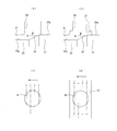
- FIG. 3 is a cross-sectional view of a main part of the liner for the front chamber of FIG. 2, in which FIG. 2 (a) is a cross-sectional view along the line AA in FIG. 2, FIG. It is CC sectional drawing. It is a perspective view of the back liner which constitutes the liner for front rooms of Drawing 2,
- the figure (a) shows the 1st example, (b) shows the 2nd example, and (c) shows the 3rd example. Yes.
- FIG. 5B is an example in which inner surface side annular grooves are provided in a plurality of through-hole portions
- FIG. E view is shown.
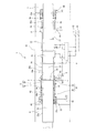
- the hydraulic striking device 1 is a “front / rear chamber alternating switching” striking device, and as shown in FIG. 1, the piston 20 is a solid cylindrical shaft member having a central axial direction. Large diameter portions 21 and 22 and small diameter portions 23 and 24 formed before and after the large diameter portions 21 and 22.
- the piston 20 is slidably fitted into the cylinder 10 so that the front chamber 2 and the rear chamber 8 are defined between the outer peripheral surface 20g of the piston 20 and the inner peripheral surface 10n of the cylinder 10, respectively. Has been.
- the step portion where the large-diameter portion 21 and the small-diameter portion 23 on the front side in the axial direction are connected is a pressure-receiving surface on the front chamber 2 side for applying thrust in the traveling direction of the piston 20,
- the pressure receiving surface on the front chamber 2 side is a conical surface 26 that decreases in diameter from the large diameter portion 21 side toward the small diameter portion 23 side.
- the step portion where the large-diameter portion 22 and the small-diameter portion 24 on the rear side in the axial direction are connected is a pressure receiving surface on the rear chamber 8 side, and in this embodiment, the pressure receiving surface on the rear chamber 8 side is large.
- the end face on the diameter part 22 side is an orthogonal surface 27 orthogonal to the axial direction.
- a control groove 25 is formed by a concave stepped portion.
- the control groove 25 is connected to the switching valve mechanism 9 via a plurality of control ports.
- the front chamber 2 and the rear chamber 8 are connected to the switching valve mechanism 9 via the high / low pressure switching ports 5 and 85, respectively.
- the switching valve mechanism 9 allows hydraulic oil to be supplied and discharged at a desired timing, so that the front chamber 2 and the rear chamber 8 are alternately communicated with the high-pressure circuit 91 and the low-pressure circuit 92, respectively, and the pressure receiving surface is made of hydraulic oil.
- a front head 6 and a back head 7 corresponding to a striking device such as a rock drill or a breaker are mounted on the front and rear of the cylinder 10, respectively.
- the front chamber 2 has a front chamber liner 30 provided in front of the front chamber 2 and fitted to the cylinder inner peripheral surface 10n.
- An annular seal retainer 32 is fitted to the cylinder inner peripheral surface 10 n on the front side of the front chamber liner 30.
- packing or the like is fitted in a plurality of annular grooves 32a formed at appropriate positions on the inner and outer peripheral surfaces of the seal retainer 32, thereby preventing the hydraulic oil from leaking to the front of the front chamber 2.
- the rear chamber 8 has a cylindrical rear chamber liner 80 provided behind the rear chamber 8 and fitted to the cylinder inner peripheral surface 10n.
- the rear chamber liner 80 integrally includes a rear chamber defining portion 81, a bearing portion 82, and a seal retainer portion 83 in order from the front in the axial direction.
- the rear chamber 8 is defined by a cylindrical space on the front inner periphery of the rear chamber defining portion 81, a liquid chamber space between the inner peripheral surface of the cylinder 10 and the outer peripheral surface of the small diameter portion of the piston 20.
- a rear chamber passage 85 is connected to the inner peripheral surface of the cylinder 10 that defines the rear chamber 8.
- the bearing portion 82 is in sliding contact with the outer peripheral surface of the small-diameter portion on the rear side of the piston 20 and pivotally supports the rear portion of the piston 20.
- a drain communication hole 84 is formed in the radial direction between the bearing portion 82 and the seal retainer 83, and the communication hole 84 is connected to a rear chamber low pressure port (not shown).
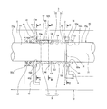
- the front chamber liner 30 is composed of a pair of front liner 40 and rear liner 50 in the axial direction. That is, in the present embodiment, the front chamber liner 30 is divided by the separate liners on the front side and the rear side in the axial direction. In the present embodiment, the front liner 40 is not provided with a liquid chamber, the liquid liner space is provided only in the rear liner 50, and the liquid chamber space formed in communication with the front chamber 2 at the rear portion of the rear liner 50. Is the cushion chamber 3.
- the cushion chamber 3 has a liquid chamber as a closed space when the large-diameter portion 21 of the piston 20 intrudes. 20 movements are restricted.
- the front liner 40 is made of a copper alloy, and has a flange portion 41 that protrudes in an annular shape toward the radially outer side at the front end portion, as shown in an enlarged view in FIG.
- the rear portion is also a cylindrical bearing portion 42.
- a drain port 45 having an annular shape is formed between the outer periphery of the flange portion 41 and the inner peripheral surface of the cylinder 10, and the drain port 45 is connected to a drain passage 49.
- the front liner 40 has an outer circumferential surface of the small-diameter portion 23 of the piston 20 having a facing gap narrower than a predetermined facing gap (clearance between the outer diameter of the piston 20 and the inner diameter of the liner) of the small-diameter portion 54 on the inner periphery of the front end side of the rear liner 50. It is in sliding contact with 23g.
- a plurality of annular oil grooves 40m are separated in the axial direction on the sliding contact surface 40n on the inner periphery of the front liner 40 to form a labyrinth.
- the front liner 40 is not provided with a liquid chamber space other than the oil groove 40m, and serves as a bearing for slidingly supporting the piston 20.
- the rear end surface 42t of the front liner 40 is in contact with the front end surface 50t of the rear liner 50, and a plurality of first end surface grooves 46 are provided on the rear end surface 42t of the front liner 40 so as to be spaced apart from each other in the circumferential direction.
- a passage is formed along the radial direction.
- the plurality of first end face grooves 46 are spaced apart in the circumferential direction and equally distributed at four locations (see FIG. 3B).
- a plurality of slits 48 are formed as axial communication paths along the axial direction on the outer peripheral surface 42g of the cylindrical bearing portion 42 in accordance with the formation position of the first end surface groove 46. ing.
- the plurality of slits 48 are equally arranged at four locations in accordance with the position of the first end face groove 46 (see FIG. 3A). Further, a plurality of second end face grooves 47 are formed as radial communication paths along the radial direction on the surface of the front liner 40 facing the rear side of the collar portion 41 in accordance with the positions of the plurality of slits 48. .
- the plurality of second end surface grooves 47 communicate with the drain port 45 provided on the outer periphery of the flange portion 41 of the front liner 40.
- the hydraulic oil in the cushion chamber 3 of the rear liner 50 is passed through the predetermined gap of the small-diameter portion 54 on the front end side of the rear liner 50, and further, “first end surface groove 46 to slit 48 to second end surface groove 47 to It is possible to escape to the drain passage 49 through the drain port 45 ".
- this circuit functions as a “drain circuit”.
- first drain circuit the drain circuit of pressure oil passing through the liner bearing portion (opposite clearance in the inner and outer diameter direction between the small diameter portion 23 of the piston 20 and the sliding contact surface 40 n on the inner periphery of the front liner 40).
- second drain circuit the drain circuit of pressure oil
- the passage areas of the first end face groove 46, slit 48, and second end face groove 47 are set to substantially equal areas.
- the “total passage area of the communication holes” obtained by adding the passage areas of the plurality of communication holes is the “clearance amount of the liner bearing portion”.
- it is set to an area within a predetermined range defined in the following (Equation 1), whereby the leak amount of pressure oil from the “second drain circuit” is limited to a predetermined amount.
- the clearance amount of the liner bearing portion is an area of an annular clearance formed by a facing clearance in the inner and outer diameter direction between the small diameter portion 23 of the piston 20 and the sliding contact surface 40 n on the inner periphery of the front liner 40. is there. 0.1 Apf ⁇ A ⁇ 2.5 Apf (Formula 1) Where Apf: liner bearing clearance A: total passage area of communication hole
- the rear liner 50 is made of an alloy having higher mechanical strength than the front liner 40 made of the copper alloy.
- the mechanical strength of the alloy steel is improved by heat treatment of the alloy steel. For example, carburizing, quenching, and tempering can be performed on the case-hardened steel to form a hardened layer on the surface.
- the rear liner 50 has a cylindrical shape, and the outer diameter of the cylindrical shape is the same as the outer diameter of the bearing portion 42 of the front liner 40.
- the inner diameter of the rear liner 50 is such that the inner diameter of the inner peripheral portion 50n on the rear end side is a slidable contact surface with a slight gap from the large diameter portion 21 of the piston 20.
- the dimension of the small-diameter portion 54 on the inner periphery of the front end side of the rear liner 50 is larger than the inner diameter dimension of the sliding contact surface 40 n on the inner periphery of the front liner 40, and the liner bearing described above with respect to the outer peripheral surface of the piston 20.
- a predetermined facing gap larger than the clearance of the part is separated.
- An annular front chamber port 4 is formed between the outer peripheral surface 50g on the rear side of the rear liner 50 and the inner peripheral surface of the cylinder 10, and the front chamber for switching the high and low pressures of the front chamber 2 to the front chamber port 4 is formed.
- a passage 5 is connected.
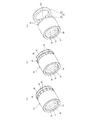
- the rear liner 50 of the present embodiment has the extending portion 55 that extends rearward from the front chamber port 4.
- the rear liner 50 is formed with an outer surface-side annular groove 56 on the outer peripheral surface of the extending portion 55 at a position facing the front chamber port 4, and the inner periphery of the extending portion 55.
- An inner surface side annular groove 57 is formed on the surface.
- a plurality of circumferentially spaced through holes 58 are formed in the inner and outer annular grooves 56 and 57 in the radial direction.
- the plurality of through holes 58 are equally arranged in the circumferential direction (in the example shown in FIG. 3C, the through holes 58 are equally arranged at 16 locations).
- the shape of the plurality of through-holes 58 is not particularly limited. For example, as shown in FIG. 4 (a) or a rectangle (the corner is R-shaped) or an ellipse, as shown in FIG. 4 (b). Can do. If the through hole 58 has a “slot shape (long hole shape)” in which the circumferential direction is longer than the axial direction, such as a rectangle or an ellipse, the passage area of each through hole 58 is increased. This is preferable for reducing the generation of cavitation by suppressing the flow rate of the cavitation.
- the rear liner 50 can be further divided.
- a split structure is formed at the position of the rear side edge surface of the through-hole 58 having the “slot shape” shown in FIG. 4B, so that the rear liner (front) 63 and the rear liner ( The rear liner 50 is composed of the rear 64.
- the column part 62 formed between the through holes 58 adjacent in the circumferential direction extends from the rear end of the rear liner (front) 63 toward the rear. It is a beam.
- the cushion chamber 3 is formed on the inner peripheral surface on the rear side of the rear liner 50.
- the cushion chamber 3 includes a first annular part 51 on the rear side in the axial direction and a second annular part 52 formed in front of the first annular part 51.
- a portion where the first annular portion 51 and the second annular portion 52 are connected is a conical surface 59 whose diameter increases from the first annular portion 51 side toward the second annular portion 52 side.
- the first annular portion 51 communicates with the inner surface side annular groove 57 over the entire circumference at the rear in the axial direction.
- the first annular portion 51 has a diameter (small diameter) shallower than the depth (inner diameter) of the inner surface side annular groove 57, and the rear side thereof is formed adjacent to the front side of the inner surface side annular groove 57.
- the second annular portion 52 has a larger diameter than the first annular portion 51, and the rear of the second annular portion 52 is formed adjacent to the front of the first annular portion 51.
- An end surface on the front side that forms the second annular portion 52 is an orthogonal surface 53 that is orthogonal to the axial direction.
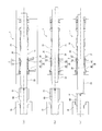
- the rock drill has a shank rod 60 in front of the piston 20 of the hydraulic striking device 1.
- the shank rod 60 has a spline 61 formed at the rear, and is supported by the front cover 70 so as to be slidable in the axial direction within a predetermined range.
- the shank rod 60 is restricted in its rearward movement limit by a damper mechanism (not shown).
- the rock drill includes a feed mechanism and a rotation mechanism (not shown), and the shank rod 60 can be rotated by a rotation mechanism meshing with the spline 61, and the cylinder 10 side of the hydraulic striking device 1 is a feed mechanism. Is fed according to the amount of crushing.
- the hydraulic striking device 1 when hydraulic oil is supplied and discharged at a predetermined timing by the switching valve mechanism 9, the front chamber 2 and the rear chamber 8 are connected to the high and low pressure switching ports 5 and 85, respectively.
- the high pressure circuit 91 and the low pressure circuit 92 are alternately communicated, whereby the piston 20 is repeatedly advanced and retracted in the cylinder 10. That is, in the hydraulic striking device 1, the hydraulic oil on the front chamber 2 side does not resist the movement of the piston in the striking direction due to the “front / rear chamber alternating switching system” striking. Therefore, it is suitable for improving the hitting efficiency.
- the shank rod 60 moves forward from the normal striking position as shown in FIG.
- a "shank rod advance state" occurs.
- the cushion chamber 3 communicating with the front chamber 2 is provided.
- the cushion chamber 3 restricts the movement of the piston by closing the liquid chamber when the large diameter portion 21 of the piston 20 enters the cushion chamber 3.
- the end of the large diameter portion 21 of the piston 20 stays in the cushion chamber 3, so The large diameter portion 21 of the piston 20 can be prevented from colliding with the cylinder 10.
- FIG. 7 shows a comparative example for this embodiment.
- a shank rod 160 is disposed in front of the piston 120.
- An annular front chamber port 104 is formed on the front side inside the cylinder 110, and an integrated front chamber liner 130 made of a copper alloy is fitted to the inner surface of the cylinder 110 in front of the front chamber port 104.
- a liquid chamber space filled with hydraulic oil is defined at the rear portion of the front chamber liner 130, and the liquid chamber space is a cushion chamber 103 communicating with the front chamber 102.
- the piston 120 hits the rear end of the shank rod 160 when the hitting efficiency is maximum.
- a shock wave generated by the hit is propagated to the bit (not shown) at the tip through the rod on the tip of the shank rod 160 and used as drilling energy.
- the bit does not land normally due to entering the hollow zone, the bit, the rod and the shank rod 160 are fastened with screws, so Thus, a state of projecting forward (a state in which the shank rod 160 has advanced from the normal striking position) occurs (hereinafter also referred to as “shank rod advance state”).
- the cushion chamber 3 is defined as “one or more communication holes that pass through a portion other than the liner bearing portion” by the “second drain circuit”.
- the hydraulic oil in the cushion chamber 3 is always communicated with the low-pressure circuit via a passage formed by the end face groove 46, the slit 48, and the second end face groove 47 ". That is, the cushion chamber 3 has the “second drain circuit” provided separately from the drain circuit that guides the hydraulic oil passing through the liner bearing portion of the liner 30 for the front chamber to the drain passage 49 that is a low-pressure circuit.
- the pressure oil is compressed in the cushion chamber 3 to be in an ultrahigh pressure state, the hydraulic oil flowing out from the cushion chamber 3 in the front chamber liner 30 can be released from the “second drain circuit”.
- the compression in the cushion chamber 3 is relieved, so that the increase in the oil temperature of the hydraulic oil is also suppressed. Furthermore, since the flow rate of the hydraulic oil flowing into the front chamber 2 is reduced, the occurrence of local cavitation is suppressed. Next, although the front chamber 2 is switched to a high pressure by the switching valve mechanism 9, since the cavitation is suppressed, heat generation due to the compression of the cavitation is mitigated, and the rise in the operating oil temperature can be dramatically reduced.
- the expansion of the copper alloy portion of the front chamber liner 30 (in this embodiment, the front liner 40 constituting the front chamber liner 30) associated therewith is also relieved, so that the sliding contact location with the front chamber liner 30 is reduced.
- the occurrence of “galling” of the piston 20 can be reduced.
- the passage area due to the “first drain circuit” rapidly decreases due to the expansion due to the temperature rise, whereas the passage area due to the “second drain circuit” is hardly affected by the temperature rise.
- the pressure oil supplied to the front chamber 2 by valve switching is larger than the inner diameter of the rear liner 50 and the piston 20.
- the piston 20 is supplied into the cushion chamber 3 from the gap of the diameter portion 21 and turns backward. At this time, a part of the pressure oil is discharged from the “second drain circuit”. The pressure rise is moderate. Accordingly, the retreat speed of the piston 20 is slowed, and the number of hits per hour in the “shank rod advance state” is reduced, so that the oil temperature rise in the front chamber 2 is alleviated.
- the total passage area of the passage composed of the “first end face groove 46 to the slit 48 to the second end face groove 47” as the plurality of communication holes is equal to the clearance amount of the liner bearing portion. Since it is set to an area within the predetermined range defined in Equation 1), while suppressing the reduction of the striking efficiency at the time of normal striking as much as possible, in the cushion chamber as in the “shank rod advance state”, etc. An increase in hot water temperature when the pressure oil is compressed to an ultra-high pressure state can be suppressed.
- the second drain circuit of the present embodiment passes the hydraulic oil of the cushion chamber 3 through the first end surface groove 46 that is a radial communication path, the slit 48 that is an axial communication path, and the drain port 45 in this order. Therefore, since the drain passage 49 of the low pressure circuit is always in communication, a dedicated low pressure port is not required for the “second drain circuit”. Therefore, the “second drain circuit” can be provided while simplifying the structure.
- the hydraulic striking device of the “front / rear chamber alternating switching method” causes a sudden pressure fluctuation of the hydraulic oil in the front chamber in a normal striking phase in which the piston reverses from the striking process in which the piston moves forward and shifts to the retreating process.
- the hydraulic oil pressure fluctuation problem in the front chamber is not a serious problem in the hydraulic rear impact device of the “rear chamber alternate switching method” because the front chamber is always in communication with the high pressure circuit.
- a negative pressure state occurs, so that cavitation is likely to occur. Also, erosion due to impact pressure due to the disappearance of cavitation is likely to occur.
- a shank rod is arranged in front of the piston, and the piston moves forward to hit the rear end of the shank rod.
- the hydraulic striking device of the “front / rear chamber alternate switching system” in the striking phase, when the front chamber is communicated with the low pressure circuit, when the piston strikes the shank rod, the piston is suddenly braked. At this time, even if the piston is suddenly braked, the hydraulic oil continues to flow out due to inertia, so a negative pressure state occurs in the front chamber. Therefore, cavitation tends to occur when the pressure of the hydraulic oil becomes lower than the saturated vapor pressure for a very short time.
- the cushion chamber 3 is formed adjacent to the first annular portion 51 on the rear end side and the front of the first annular portion 51.
- the second annular portion 52 having a diameter larger than that of the first annular portion 51, the pressure of the hydraulic oil is reduced by the volume expansion by the second annular portion 52 provided on the front side of the first annular portion 51. Can be relaxed. Therefore, the occurrence of cavitation in the front chamber 2 can be suppressed. Moreover, even if cavitation occurs, it is possible to suppress rupture and erosion. Therefore, it is more suitable for suppressing the hot water temperature rise.
- the front end surface forming the second annular portion 52 of the cushion chamber 3 is an orthogonal surface 53 orthogonal to the axial direction, the cavitation is temporarily performed in the second annular portion 52 of the cushion chamber 3. Even if erosion occurs and erosion is reached, cavitation toward the front liner 40 side having a bearing function may be retained in the cushion chamber 3 by the orthogonal surface 53, and erosion may be generated at a location that does not affect sliding with the piston. it can. For this reason, it is possible to minimize a problem caused by cavitation erosion and to prevent an impossibility of hitting immediately.
- the front chamber liner 30 is constituted by a front liner 40 and a rear liner 50 that are divided into two in the axial direction, and the front liner 40 is made of a copper alloy.
- a liquid chamber space other than the oil groove 40m is not provided to provide a bearing member that supports the sliding of the piston 20, and the rear liner 50 is made of an alloy steel having a hardened layer formed on the surface thereof. Since the liquid chamber space that is communicated and filled with hydraulic oil is provided as the cushion chamber 3, the cavitation erosion is handled by the inner wall surface of the liquid chamber space of the cushion chamber 3 of the rear liner 50 made of high-hardness steel.
- the bearing function for slidingly supporting the piston 20 can be handled by a copper alloy front liner 40 that does not provide a liquid chamber space.
- the rear liner 50 resists the impact pressure caused by the disappearance of cavitation in the front chamber 2 and increases the resistance to erosion. be able to. Therefore, the malfunction caused by cavitation erosion can be minimized.
- cavitation erosion in the front chamber is caused by the high and low pressure switching port that supplies and discharges hydraulic oil from the front chamber. It was confirmed that the occurrence was unevenly distributed on the farthest side in the circumferential direction with respect to the opening.
- the front chamber port 4 formed in an annular shape is provided on the inner surface of the cylinder 10, and before the high and low pressures are switched so as to communicate with the front chamber port 4.
- the rear liner 50 connected to the chamber passage 5 and constituting the front chamber liner 30 extends to a position facing the front chamber port 4 and is spaced circumferentially on a surface facing the front chamber port 4. Since the plurality of through holes 58 are formed so as to penetrate in the radial direction, the plurality of through holes 58 serve as a dispersion region of the generated cavitation.
- cavitation generated inside the rear liner 50 constituting the front chamber liner 30 is dispersed before entering the front chamber port 4 by the plurality of through holes 58 formed in the rear liner 50. Therefore, even if cavitation occurs, the uneven distribution of cavitation in the portion farthest in the circumferential direction with respect to the opening of the opening of the front chamber passage 5 is alleviated. Therefore, intensive erosion in this portion can be effectively suppressed.
- the rear side of the rear liner extends to the rear of the front chamber port, the occurrence of erosion on the cylinder inner diameter sliding surface can be prevented. Therefore, consumable parts due to erosion can be minimized.
- the plurality of through holes 58 are provided in an inner surface side annular groove 57 formed on the inner peripheral surface of the extending portion 55, and the first annular portion 51 has an axial rear side. Since it communicates with the inner surface side annular groove 57 over the entire circumference, the cushioning effect by the cushion chamber 3 can be started at a desired position, and a reduction in impact efficiency can be prevented.
- the large-diameter portion 21 of the piston 20 is directly connected to the through-hole 58. It will pass in sliding contact. Therefore, when the large-diameter portion 21 of the piston 20 passes through the portion of the through hole 58, the change in the pressure oil outflow passage area toward the low pressure side (the front chamber port 4 side) as shown in FIG. (The two-dot chain line in the figure shows an image of the process in which the large-diameter end ridge line passes). Therefore, the cushioning action is generated from the stage before entering the cushion chamber 3, and the impact efficiency is lowered.
- the plurality of column portions 62 formed between the through holes 58 adjacent in the circumferential direction are cantilever beams.
- the rear liner 50 is divided by dividing the rear liner 50 at the position of the rear side edge surface of the through hole 58 having a “slot shape”. It is preferable that the rear liner 50 is composed of 63 and the rear liner (rear) 64. That is, when a surge pressure is generated as the piston 20 reciprocates, in the case of a column portion having a double-sided structure as shown in FIG. Acts as Therefore, when erosion progresses in the column portion, the column portion may not withstand the tensile pressure and may be broken.
- the hydraulic striking device 1 of the above embodiment has been described by taking the “front / rear chamber alternate switching system” striking device as an example.
- the present invention is not limited to this, and the present invention switches the front chamber to the low pressure circuit when the piston moves forward. It can be applied to the hydraulic striking device.
- the present invention can also be applied to a “front chamber alternate switching type” striking device as disclosed in Patent Document 3.
- the rear chamber is always communicated with the high pressure circuit, while the front chamber is alternately communicated with the high pressure circuit and the low pressure circuit by the switching valve mechanism.
- the front chamber communicates with the high-pressure circuit
- the front and rear pressure receiving areas are made different so that the piston moves in the backward direction, whereby the forward and backward movement of the piston is repeated in the cylinder. Therefore, since the front chamber is switched to the low pressure circuit when the piston moves forward, the front chamber becomes a low pressure when the piston moves forward, and problems such as preventing the occurrence of galling of the piston due to the oil temperature rise in the front chamber are similar. Since it occurs in the mechanism, the present invention can be applied.
- the front chamber liner 30 has been described as being configured by the front liner 40 and the rear liner 50 that are divided into the front and rear in the axial direction.
- the present invention is not limited to this, and the comparative example of FIG.
- the front chamber liner 30 may be constituted by a monolithic liner.
- the rear liner 50 increases resistance to erosion against the impact pressure caused by the disappearance of cavitation in the front chamber 2.
- the front chamber liner 30 is composed of a front liner 40 and a rear liner 50 that are divided in the longitudinal direction, and the rear liner 50 is an alloy having higher mechanical strength than the front liner 40. It is preferable to make it.
- the rear liner 50 is made of “hardened steel” having a hardened layer formed on the surface by carburizing, quenching and tempering.
- the back liner 50 should just be a product made from an alloy whose mechanical strength is higher than the front liner 40.
- various curing treatments such as heat treatment, physical treatment, and chemical treatment can be employed.
- various mechanical structural alloy steels can be employed in addition to chromium steel, chromium molybdenum steel, nickel chromium steel, and the like.
- the mechanical strength is not limited to forming a hardened layer on the surface, the whole may be hardened using an alloy tool steel such as SKD, and the presence or absence of a hardening treatment is not limited, For example, an alloy such as stellite may be used.
- the rear liner 50 extends to a position facing the front chamber port 4, and a plurality of through holes 58 spaced in the circumferential direction are formed on the surface facing the front chamber port 4 in the radial direction.
- the position of the rear end of the front chamber liner 30 is not limited to this, as shown in the comparative example of FIG. It is also possible to set the length to the position in front of the chamber port 4.
- the rear liner 50 is extended to a position facing the front chamber port 4 in order to more suitably mitigate the uneven distribution of cavitation in the portion farthest in the circumferential direction with respect to the opening of the front chamber passage 5.
- a plurality of through holes 58 that are spaced apart in the circumferential direction are formed in the surface facing the front chamber port 4 so as to penetrate in the radial direction. Further, in order to prevent the occurrence of erosion at the inner diameter portion of the cylinder 10, it is preferable to extend the rear liner 50 to the rear side of the front chamber port 4.
- the boundary portion between the front liner 40 and the rear liner 50 which is a position in front of the cushion chamber 3, is separated in the circumferential direction in the radial direction.
- the first end surface groove 46 is formed along the first end surface groove 46, and a plurality of communication holes including “first end surface groove 46 to slit 48 to second end surface groove 47” are always communicated with the low-pressure circuit.
- the “second drain circuit” is formed separately from the “first drain circuit” of the pressure oil passing through the liner bearing portion, and communicates with the cushion chamber 3 through a portion other than the liner bearing portion. If so, various modifications are possible.
- the “second drain circuit” it is preferable to provide a plurality of communication holes at a position in front of the cushion chamber 3, but the plurality of communication holes are formed at the boundary between the front liner 40 and the rear liner 50. It is not limited to the department. The same applies to the case where the front chamber liner 30 is constituted by a monolithic liner, as well as the case where the front chamber liner 30 is constituted by the front liner 40 and the rear liner 50.
- the front chamber liner 30 is constituted by the front liner 40 and the rear liner 50, an increase in the oil temperature in the cushion chamber 3 is suppressed, and the piston 20 at the sliding contact position with the front chamber liner 30 is suppressed.
- a plurality of radial communication paths are formed at the boundary between the front liner 40 and the rear liner 50 so as to be circumferentially separated and penetrated along the radial direction. It is preferable to configure the “second drain circuit” so that the radial communication path is always in communication with the low-pressure circuit.
- the cushion chamber 3 is configured from the first annular portion 51 and the second annular portion 52 having a larger diameter than the first annular portion 51 with respect to the liquid chamber shape and volume of the cushion chamber 3,
- the front end surface forming the second annular portion 52 is the orthogonal surface 53 orthogonal to the axial direction
- the present invention is not limited to this, and the liquid chamber shape of the cushion chamber 3 is, for example, illustrated in FIG. As shown in the comparative example of FIG. 7, it may be composed of only one annular portion.
- the cushion chamber 3 is provided on the first annular portion 51 and on the front side of the first annular portion 51. It is preferable that the second annular portion 52 has a large volume. Moreover, you may comprise the front end surface which forms the 2nd ring part 52 by an inclined surface like the form shown in the comparative example of FIG. 7, for example. However, in order to more suitably suppress cavitation toward the front liner 40 having a bearing function, the front end surface forming the second annular portion 52 is preferably an orthogonal surface 53 orthogonal to the axial direction. .
Abstract
Description
特許文献1に記載の液圧式打撃装置は、軸方向中央の大径部と、その大径部の前後に形成された小径部とを有するピストンを備えている。そして、このピストンが、シリンダ内に摺嵌して設けられることで、ピストンの外周面とシリンダの内周面との間に前室と後室とがそれぞれ画成されている。
前室は常時高圧回路に連通される一方、後室は切換弁機構により高圧回路と低圧回路のそれぞれに交互に連通される。後室が高圧回路に連通時は、打撃方向にピストンが移動するように前後の受圧面積を異ならせており、これにより、シリンダ内でピストンの前進および後退が繰返されるようになっている(以下、「後室交互切替方式」ともいう)。 As this type of hydraulic striking device, for example, a technique described in
The hydraulic striking device described in
The front chamber is always communicated with the high pressure circuit, while the rear chamber is alternately communicated with the high pressure circuit and the low pressure circuit by the switching valve mechanism. When the rear chamber communicates with the high-pressure circuit, the front and rear pressure receiving areas are made different so that the piston moves in the striking direction, so that the forward and backward movements of the piston are repeated in the cylinder (hereinafter referred to as the following). , Also called “rear chamber alternating switching method”).
これに対し、例えば特許文献2には、前室と後室とを交互に高圧回路と低圧回路とに切り替える液圧式打撃装置が開示されている(以下、「前後室交互切替方式」ともいう)。「前後室交互切替方式」の液圧式打撃装置であれば、ピストン前進時に前室を低圧回路に切り替えるため、前室側の作動油が打撃方向へのピストンの移動に抗することがない。したがって、打撃効率を向上させる上で好適である。 By the way, the hydraulic striking device described in
On the other hand, for example,
そこで、本発明は、このような問題点に着目してなされたものであって、ピストン前進時に前室を低圧回路に切り替える方式の液圧式打撃装置における、前室でのキャビテーションを防止または抑制し得る液圧式打撃装置を提供することを課題とする。 Further, the inventors of the present invention found that the problem of cavitation in the anterior chamber is that the anterior chamber becomes a low pressure when the piston moves forward because the anterior chamber is switched to a low pressure circuit when the piston moves forward. I thought. That is, in addition to the above-mentioned “front and rear chamber alternate switching method” in which the front chamber becomes low pressure when the piston moves forward, the “front chamber alternate switching method” in which the rear chamber is always connected to high pressure and the front chamber is alternately switched between high pressure and low pressure. (For example, see Patent Document 3), there is a similar problem.
Therefore, the present invention has been made paying attention to such problems, and prevents or suppresses cavitation in the front chamber in a hydraulic striking device that switches the front chamber to a low pressure circuit when the piston moves forward. It is an object of the present invention to provide a hydraulic striking device to be obtained.
図7に前室にクッション室を設けた一例を示すように、この例では、前室用ライナ130の後部に、作動油が満たされる液室空間が画成され、この液室空間が前室102と連通するクッション室103になっている。クッション室103は、ピストン120の大径部121がクッション室103に侵入したときに液室を閉空間にしてピストン120の移動を規制する。このときに、クッション室103から前室102側へ圧油が高速で流出すると、圧油の流速が高い箇所では局所的なキャビテーションの発生の原因となる。 Here, in the hydraulic striking device, for example, in a rock drill (drifter), a cushion chamber is provided in the front chamber as a braking mechanism in order to prevent the large-diameter portion of the piston from colliding with the cylinder at the piston front stroke end. Things have been done.
As shown in an example in which a cushion chamber is provided in the front chamber in FIG. 7, in this example, a liquid chamber space filled with hydraulic oil is defined at the rear portion of the
0.1Apf<A<2.5Apf ・・・・・(式1)
但し、Apf:ライナ軸受部のクリアランス量
A:連通孔の総通路面積
このような構成であれば、通常打撃時の打撃効率の低下を可及的に抑えつつも、「シャンクロッド前進状態」時などのように、クッション室内で圧油が圧縮されて超高圧状態となるときの湯温上昇を抑制する上で好適である。なお、一または複数の連通孔が低圧回路に常に連通されてなる第二のドレン回路に、絞り機構を付設することは好ましい。 Here, in the hydraulic striking device according to the first aspect of the present invention, the second drain circuit is a hydraulic oil in the cushion chamber via one or a plurality of communication holes passing through a portion other than the liner bearing portion. The total passage area of the one or more communication holes is the clearance amount of the liner bearing portion (inner and outer diameter directions between the small diameter portion of the piston and the sliding surface of the inner periphery of the front liner). Is preferably set to an area within a predetermined range defined in the following (Equation 1).
0.1 Apf <A <2.5 Apf (Formula 1)
However, Apf: liner bearing clearance amount A: total passage area of the communication hole With such a configuration, a decrease in impact efficiency at the time of normal impact is suppressed as much as possible, while in the “shank rod advance state” Thus, it is suitable for suppressing the rise in the hot water temperature when the pressure oil is compressed in the cushion chamber to be in an ultra-high pressure state. In addition, it is preferable to attach a throttle mechanism to the second drain circuit in which one or a plurality of communication holes are always communicated with the low-pressure circuit.
そこで、本発明の第二の態様に係る液圧式打撃装置において、前記シリンダ内面に、前記前室用ライナの後方側の外周面に対向して円環状に形成された前室ポートを有し、該前室ポートに連通するように前記前室の作動油の高低圧を切替える前室通路が接続され、前記前室用ライナは、前記前室ポートに対向する位置まで延設されるとともに、前記前室ポートに対向する面に、周方向に離隔する複数の貫通孔が径方向に貫通して形成されていることは好ましい。 Further, according to the results of the experimental study by the present inventor, the cavitation erosion in the front chamber is unevenly distributed on the farthest side in the circumferential direction with respect to the opening of the front chamber passage through which the hydraulic oil in the front chamber is supplied and discharged. It was confirmed that this occurred.
Therefore, in the hydraulic striking device according to the second aspect of the present invention, the cylinder inner surface has a front chamber port formed in an annular shape facing the outer peripheral surface on the rear side of the front chamber liner, A front chamber passage for switching high and low pressures of hydraulic fluid in the front chamber is connected so as to communicate with the front chamber port, and the front chamber liner extends to a position facing the front chamber port, and It is preferable that a plurality of through-holes spaced in the circumferential direction are formed through the surface facing the anterior chamber port in the radial direction.
これにより、前室用ライナの内側で発生したキャビテーションは、後ライナの複数の貫通孔によって前室ポートに入る前に分散される。そのため、仮にキャビテーションが発生した場合であっても、前室通路の開口部に対して周方向で最も離れた側の部分へのキャビテーションの偏在が緩和される。したがって、この部分における集中的なエロージョンを効果的に抑制することができる。さらに、後ライナの後側を前室ポートの後方まで延設しているので、シリンダ内径摺動面でのエロージョンの発生を防止できる。そのため、エロージョンによる消耗部品を最小限に抑えることができる。 In such a configuration, a front chamber port formed in an annular shape is provided on the inner surface of the cylinder, and a front chamber passage for switching between high and low pressures is connected so as to communicate with the front chamber port. A plurality of through-holes extending in a radial direction are formed in a surface facing the front chamber port and extending in a radial direction on a surface facing the front chamber port, so that a plurality of through-holes in the rear liner are formed. The holes serve as a dispersion region for the generated cavitation.
Accordingly, cavitation generated inside the front chamber liner is dispersed before entering the front chamber port by the plurality of through holes of the rear liner. Therefore, even if cavitation occurs, the uneven distribution of cavitation in the portion farthest in the circumferential direction with respect to the opening of the front chamber passage is alleviated. Therefore, intensive erosion in this portion can be effectively suppressed. Furthermore, since the rear side of the rear liner extends to the rear of the front chamber port, the occurrence of erosion on the cylinder inner diameter sliding surface can be prevented. Therefore, consumable parts due to erosion can be minimized.
ここで、本発明の第三の態様に係る液圧式打撃装置において、前記第二円環部を形成する前方側の端面は、軸方向と直交する直交面とされていることは好ましい。このような構成であれば、仮にクッション室の第二円環部内でキャビテーションが発生してエロージョンに到っても、第二円環部を形成する前方側の端面は、軸方向と直交する直交面とされているので、軸受機能をもつ前ライナ側に向かうキャビテーションをこの直交面によって第二円環部内に留め、エロージョンをピストンとの摺動に影響の無い箇所に発生させることができる。そのため、キャビテーションエロージョンによって引き起こされる不具合を最小限に止め、直ちに打撃不能状態となることを防止することができる。 According to the hydraulic striking device according to the third aspect of the present invention, the cushion chamber is formed adjacent to the first annular portion on the rear end side and the front of the first annular portion. Since the second annular portion having a larger diameter than the annular portion is provided, the pressure drop of the hydraulic oil can be reduced by the volume expansion by the second
Here, in the hydraulic striking device according to the third aspect of the present invention, it is preferable that the front end surface forming the second annular portion is an orthogonal surface orthogonal to the axial direction. With such a configuration, even if cavitation occurs in the second annular portion of the cushion chamber and erosion occurs, the front end surface forming the second annular portion is orthogonal to the axial direction. Therefore, the cavitation toward the front liner side having a bearing function can be retained in the second annular portion by this orthogonal surface, and erosion can be generated at a position that does not affect the sliding with the piston. For this reason, it is possible to minimize a problem caused by cavitation erosion and to prevent an impossibility of hitting immediately.
本実施形態の液圧式打撃装置1は、「前後室交互切替方式」の打撃装置であって、図1に示すように、ピストン20は、中実円筒状の軸部材であって、軸方向中央の大径部21、22と、この大径部21、22の前後に形成された小径部23、24とを有する。そして、このピストン20が、シリンダ10内に摺嵌して設けられることで、ピストン20の外周面20gとシリンダ10の内周面10nとの間に前室2と後室8とがそれぞれ画成されている。なお、軸方向前側の大径部21と小径部23とが接続する段部は、ピストン20の進行方向に推力を与えるための、前室2側での受圧面とされ、本実施形態では、前室2側での受圧面は、大径部21側から小径部23側に向けて縮径する円錐面26となっている。一方、軸方向後側の大径部22と小径部24とが接続する段部は、後室8側での受圧面とされ、本実施形態では、後室8側での受圧面は、大径部22側の端面が、軸方向と直交する直交面27となっている。 Hereinafter, an embodiment of the present invention will be described with reference to the drawings as appropriate.
The hydraulic
後室用ライナ80は、軸方向前方から順に、後室画成部81、軸受部82、シールリテーナ部83を一体に有する。後室画成部81の前側内周の円筒状空間、シリンダ10内周面およびピストン20の小径部の外周面との間の液室空間により上記後室8が画成されている。後室8を画成するシリンダ10内周面に連通して後室通路85が接続される。軸受部82は、ピストン20の後方側の小径部外周面に摺接されてピストン20の後部を軸支している。軸受部82の内周面には、複数条の円環状油溝82aが軸方向に離隔してラビリンスを形成している。シールリテーナ部83には、その内外周面の適宜の位置に形成された複数の環状溝83aにパッキン等が嵌め込まれており、後室8後方への作動油の漏れを防止している。軸受部82とシールリテーナ部83との間には、ドレン用の連通孔84が径方向に貫通形成され、この連通孔84が後室用低圧ポート(不図示)に接続される。 Here, the
The
前ライナ40は、後ライナ50の前端側内周の小径部54の所定の対向隙間(ピストン20の外径とライナ内径とのクリアランス)よりも狭い対向隙間をもってピストン20の小径部23の外周面23gに摺接している。前ライナ40の内周の摺接面40nには、複数条の円環状の油溝40mが軸方向に離間してラビリンスを形成している。前ライナ40は、この油溝40m以外には液室空間を設けておらず、ピストン20を摺動支持する軸受となっている。 Specifically, the
The
さらに、前ライナ40には、円筒状の軸受部42の外周面42gに、上記第一端面溝46の形成位置に合せて、軸方向に沿って複数のスリット48が軸方向連通路として形成されている。この例では、複数のスリット48は、上記第一端面溝46の位置に合せて4か所に等配されている(図3(a)参照)。さらに、前ライナ40のつば部41の後方側を向く面には、複数のスリット48の位置に合せて、複数の第二端面溝47が径方向に沿って径方向連通路として形成されている。 The
Further, in the
つまり、この回路がいわば「ドレン回路」として機能するようになっている。なお、ライナ軸受部(ピストン20の小径部23と前ライナ40の内周の摺接面40nとの内外径方向の対向隙間)を通る圧油のドレン回路(以下、「第一のドレン回路」ともいう)とは別個に形成されていることから、この回路を「第二のドレン回路」ということができる。 The plurality of second
In other words, this circuit functions as a “drain circuit”. In addition, the drain circuit of pressure oil (hereinafter referred to as “first drain circuit”) passing through the liner bearing portion (opposite clearance in the inner and outer diameter direction between the
0.1Apf<A<2.5Apf ・・・・・(式1)
但し、Apf:ライナ軸受部のクリアランス量
A:連通孔の総通路面積 In the communication hole composed of “first
0.1 Apf <A <2.5 Apf (Formula 1)
Where Apf: liner bearing clearance A: total passage area of communication hole
本実施形態においては、後ライナ50には、上記延設部55の外周面に、前室ポート4に対向する位置に外面側円環状溝56が形成されるとともに、延設部55の内周面に内面側円環状溝57が形成されている。そして、この内外の円環状溝56,57内に、周方向に離隔する複数の貫通孔58が径方向に穿孔されている。 An annular
In the present embodiment, the
さらに、図2に示すように、後ライナ50の後方側の内周面には、上記クッション室3が形成されている。本実施形態においては、クッション室3は、軸方向後方の第一円環部51と、この第一円環部51の前方に形成された第二円環部52とを有する。第一円環部51と第二円環部52とが接続する部分は、第一円環部51側から第二円環部52側に向けて拡径する円錐面59となっている。 As shown in FIG. 4C, the
Further, as shown in FIG. 2, the
ここで、さく孔中において、ビットが空洞帯に入るなどして正常に着岩しないと、図5(c)に示すように、シャンクロッド60が通常の打撃位置よりも前方に移動して「シャンクロッド前進状態」が生じる。このとき、ピストン前側ストローク端でピストン20の大径部21がシリンダ10と衝突することを防止するために、前室2と連通するクッション室3が設けられている。同図(c)の中心線上側に示すように、クッション室3は、ピストン20の大径部21がクッション室3に侵入したときに液室を閉空間にしてピストンの移動を規制する。これにより、同図(c)の中心線下側に示すように、ピストン20の大径部21の端部(円錐面26の位置)が、クッション室3内で留まるため、ピストン前側ストローク端でピストン20の大径部21がシリンダ10と衝突することを防止することができる。 Here, in the hydraulic
Here, in the drill hole, if the bit does not rock normally due to entering the hollow band, the
同図に示す比較例では、ピストン120の前方にシャンクロッド160が配置されている。シリンダ110の内部の前側には、円環状の前室ポート104が形成され、この前室ポート104の前方に、銅合金製の一体構造の前室用ライナ130がシリンダ110の内面に嵌合されている。そして、この前室用ライナ130の後部に、作動油が満たされる液室空間が画成され、この液室空間が前室102と連通するクッション室103になっている。 Specifically, in the hydraulic striking device of the “front / rear chamber alternate switching system”, for example, in a rock drill (drifter), a braking mechanism is used to prevent the large-diameter portion of the piston from colliding with the cylinder at the piston front stroke end. A cushion chamber is provided in the front chamber. FIG. 7 shows a comparative example for this embodiment.
In the comparative example shown in the figure, a
ここで、さく孔中においては、ビットが空洞帯に入るなどして正常に着岩しないと、ビット、ロッドおよびシャンクロッド160それぞれがネジで締結されているので、さく岩機本体に対して相対的に前方に突出する状態(シャンクロッド160が通常の打撃位置よりも前進した状態)が発生する(以下、「シャンクロッド前進状態」ともいう)。この「シャンクロッド前進状態」でピストン120が作動すると、ピストン120の大径部121がクッション室103内に侵入して制動を受けることになる。そのため、クッション室103内では圧油が圧縮されて超高圧状態となる。 The
Here, in the drill hole, if the bit does not land normally due to entering the hollow zone, the bit, the rod and the
そのため、これに伴う前室用ライナ30の銅合金部(本実施形態では、前室用ライナ30を構成する前ライナ40)の膨張も緩和されるので、前室用ライナ30との摺接箇所でのピストン20の「カジリ」の発生を低減することができる。なお、上記「第一のドレン回路」による通路面積は、温度上昇による膨張で急激に減少するのに対し、「第二のドレン回路」による通路面積は、温度上昇による影響を受けにくい。 Thereby, compared with the case where the “second drain circuit” is not provided, the compression in the
Therefore, the expansion of the copper alloy portion of the front chamber liner 30 (in this embodiment, the
さらに、本実施形態の第二のドレン回路は、クッション室3の作動油を、径方向連通路である第一端面溝46、軸方向連通路であるスリット48、およびドレンポート45をこの順に通じて低圧回路のドレン通路49に常に連通させているので、「第二のドレン回路」用として専用の低圧ポートが不要となる。よって、構造を簡素としつつ「第二のドレン回路」を設けることができる。 In the present embodiment, the total passage area of the passage composed of the “first
Further, the second drain circuit of the present embodiment passes the hydraulic oil of the
さらに、本発明者による実験研究の結果によれば、「前後室交互切替方式」の液圧式打撃装置において、前室でのキャビテーションエロージョンは、前室から作動油を給排させる高低圧切替ポートの開口部に対して周方向で最も離れた側に偏在して発生することが確認された。 Therefore, while maintaining the piston sliding support function as a necessary bearing on the
Further, according to the results of experimental research by the present inventors, in the hydraulic striking device of the “front and rear chamber alternate switching method”, cavitation erosion in the front chamber is caused by the high and low pressure switching port that supplies and discharges hydraulic oil from the front chamber. It was confirmed that the occurrence was unevenly distributed on the farthest side in the circumferential direction with respect to the opening.
これにより、前室用ライナ30を構成する後ライナ50の内側で発生したキャビテーションは、後ライナ50に形成された複数の貫通孔58によって前室ポート4に入る前に分散される。そのため、仮にキャビテーションが発生した場合でも、前室通路5の開口部の開口部に対して周方向で最も離れた側の部分へのキャビテーションの偏在が緩和される。したがって、この部分における集中的なエロージョンを効果的に抑制することができる。 On the other hand, according to the hydraulic
Thus, cavitation generated inside the
さらに、本実施形態において、複数の貫通孔58は、延設部55の内周面に形成された内面側円環状溝57内に設けられ、上記第一円環部51は、軸方向後方が内面側円環状溝57に全周に亘って連通しているので、クッション室3によるクッション効果を所期の位置で開始させて、打撃効率の低下を防止することができる。 Furthermore, since the rear side of the rear liner extends to the rear of the front chamber port, the occurrence of erosion on the cylinder inner diameter sliding surface can be prevented. Therefore, consumable parts due to erosion can be minimized.
Further, in the present embodiment, the plurality of through
つまり、ピストン20の往復に伴ってサージ圧が発生するところ、図4(b)のような両持ち構造の柱部であると、発生するサージ圧が、柱部に対して前後方向の引張り圧力として作用する。そのため、柱部の部分でエロージョンが進行すると、柱部が引張り圧力に耐えられなくなって壊れてしまうおそれがある。これに対し、図4(c)に示したように、複数の柱部62を片持ち梁とすれば、柱部62にサージ圧による引張り圧力は作用しない。そのため、サージ圧による柱部62の破壊を防止または抑制することができる。 Here, it is preferable that the plurality of
That is, when a surge pressure is generated as the
つまり、「前室交互切替方式」の打撃装置は、後室が常時高圧回路に連通される一方、前室が切換弁機構により高圧回路と低圧回路のそれぞれに交互に連通される。前室が高圧回路に連通時は、後退方向にピストンが移動するように前後の受圧面積を異ならせており、これにより、シリンダ内でピストンの前進および後退が繰返される。よって、ピストン前進時に前室を低圧回路に切り替える方式なので、ピストン前進時に前室が低圧になるため、前室での油温上昇にともなうピストンのカジリの発生を防止する等の問題が同様の作用機序にて生じることから、本発明を適用することができるのである。 For example, the hydraulic
In other words, in the “front chamber alternate switching type” striking device, the rear chamber is always communicated with the high pressure circuit, while the front chamber is alternately communicated with the high pressure circuit and the low pressure circuit by the switching valve mechanism. When the front chamber communicates with the high-pressure circuit, the front and rear pressure receiving areas are made different so that the piston moves in the backward direction, whereby the forward and backward movement of the piston is repeated in the cylinder. Therefore, since the front chamber is switched to the low pressure circuit when the piston moves forward, the front chamber becomes a low pressure when the piston moves forward, and problems such as preventing the occurrence of galling of the piston due to the oil temperature rise in the front chamber are similar. Since it occurs in the mechanism, the present invention can be applied.
しかし、前室2側で必要な軸受としてのピストン摺動支持機能を前ライナ40で維持しつつ、後ライナ50によって前室2でのキャビテーションの消滅による衝撃圧力に対抗してエロージョンに対する耐性を高める上では、上記実施形態のように、前室用ライナ30を軸方向前後に二分割した前ライナ40と後ライナ50とから構成し、後ライナ50を前ライナ40よりも機械的強度が高い合金製とすることが好ましい。 Further, for example, in the above-described embodiment, the
However, while maintaining the piston sliding support function as a necessary bearing on the
例えば、機械的強度を向上させるために、熱処理、物理的処理、化学的処理によるものなど、種々の硬化処理を採用可能である。また、材料についても、例えば、クロム鋼、クロムモリブデン鋼、ニッケルクロム鋼等の他、種々の機械構造用合金鋼を採用することができる。また、機械的強度は、表面に硬化層を形成するだけでなく、SKD等の合金工具鋼を用いて全体を硬化させてもよいし、また、硬化処理を施すことの有無も限定されず、例えばステライトのような合金を用いてもよい。 In the case where the
For example, in order to improve mechanical strength, various curing treatments such as heat treatment, physical treatment, and chemical treatment can be employed. In addition, for example, various mechanical structural alloy steels can be employed in addition to chromium steel, chromium molybdenum steel, nickel chromium steel, and the like. In addition, the mechanical strength is not limited to forming a hardened layer on the surface, the whole may be hardened using an alloy tool steel such as SKD, and the presence or absence of a hardening treatment is not limited, For example, an alloy such as stellite may be used.
しかし、前室通路5の開口部に対して周方向で最も離れた側の部分へのキャビテーションの偏在をより好適に緩和する上では、後ライナ50を、前室ポート4に対向する位置まで延設し、前室ポート4に対向する面に、周方向に離隔する複数の貫通孔58を径方向に貫通して形成することが好ましい。さらに、シリンダ10の内径部でのエロージョンの発生を防止するためにも、後ライナ50を前室ポート4の後側まで延設することは好ましい。 Further, for example, in the above-described embodiment, the
However, the
例えば、「第二のドレン回路」は、ライナ軸受部を通る圧油の「第一のドレン回路」とは別個に形成されて、ライナ軸受部以外の箇所を通ってクッション室3に連通されていれば、種々変形可能である。また、「第二のドレン回路」は、複数の連通孔をクッション室3よりも前方の位置に設けることは好ましいが、複数の連通孔の形成位置は、前ライナ40と後ライナ50との境界部に限定されない。前室用ライナ30を一体構造のライナから構成する場合は勿論、前ライナ40と後ライナ50とから前室用ライナ30を構成する場合であっても同様である。 Further, for example, in the above-described embodiment, as the “second drain circuit”, the boundary portion between the
For example, the “second drain circuit” is formed separately from the “first drain circuit” of the pressure oil passing through the liner bearing portion, and communicates with the
また、例えば上記実施形態では、クッション室3の液室形状と容積につき、第一円環部51と、これよりも大径な第二円環部52とからクッション室3を構成し、さらに、第二円環部52を形成する前方側の端面が、軸方向と直交する直交面53とされている例で説明したが、これに限定されず、クッション室3の液室形状を、例えば図7の比較例に示す形態のように、一の円環部のみから構成してもよい。 However, when the
Further, for example, in the above embodiment, the
2 前室
3 クッション室
4 前室ポート
5 前室通路
6 フロントヘッド
7 バックヘッド
8 後室
9 切換弁機構
10 シリンダ
20 ピストン
21、22 大径部
23、24 小径部
25 制御用溝部
26 円錐面
27 直交面
30 前室用ライナ
32 シールリテーナ
40 前ライナ
41 つば部
42 軸受部
45 ドレンポート
46 第一端面溝(第一の径方向連通路)
47 第二端面溝(第二の径方向連通路)
48 スリット(軸方向連通路)
49 ドレン通路
50 後ライナ
51 第一円環部
52 第二円環部
53 直交面
54 小径部
55 延設部
56 外面側円環状溝
57 内面側円環状溝
58 貫通孔
59 円錐面
62 柱部
63 後ライナ(前)
64 後ライナ(後)
80 後室用ライナ
81 後室画成部
82 軸受部
83 シールリテーナ部
84 ドレン用の連通孔
85 後室通路
91 高圧回路
92 低圧回路 DESCRIPTION OF
47 Second end face groove (second radial communication path)
48 Slit (Axial communication path)
49
64 Rear liner (rear)
80
Claims (7)
- シリンダ内に摺嵌されたピストンを前後進させて打撃用のロッドを打撃する液圧式打撃装置であって、
前記ピストンの外周面と前記シリンダの内周面との間に画成されて前後に離隔配置された前室および後室と、前記ピストンの前進時に前記前室を低圧回路に切り替えて前記ピストンの前進および後退が繰返されるように作動油を給排させる切換弁機構とを備え、
前記前室は、前記シリンダ内面に嵌合された前室用ライナを有し、前記前室用ライナには、前記前室と連通して作動油が満たされる液室空間がクッション室として設けられており、
前記クッション室は、前記前室用ライナのライナ軸受部を通る作動油を低圧回路に導くドレン回路とは別個に設けられて前記ライナ軸受部以外の箇所を通る第二のドレン回路を有することを特徴とする液圧式打撃装置。 A hydraulic striking device for striking a striking rod by advancing the piston fitted in the cylinder back and forth,
A front chamber and a rear chamber defined between the outer peripheral surface of the piston and the inner peripheral surface of the cylinder and spaced apart from each other; and when the piston moves forward, the front chamber is switched to a low pressure circuit. A switching valve mechanism for supplying and discharging hydraulic oil so that the forward and backward movements are repeated,
The front chamber has a front chamber liner fitted to the inner surface of the cylinder, and the front chamber liner is provided with a liquid chamber space communicating with the front chamber and filled with hydraulic oil as a cushion chamber. And
The cushion chamber has a second drain circuit that is provided separately from a drain circuit that guides hydraulic oil that passes through the liner bearing portion of the liner for the front chamber to a low-pressure circuit and passes through a portion other than the liner bearing portion. A hydraulic striking device. - 前記第二のドレン回路は、前記ライナ軸受部以外の箇所を通る一または複数の連通孔を介して当該クッション室内の作動油を低圧回路に常に連通させており、
前記一または複数の連通孔の総通路面積は、前記ライナ軸受部のクリアランス量に対して、下記(式1)に規定する所定範囲内の面積に設定されていることを特徴とする請求項1に記載の液圧式打撃装置。
0.1Apf<A<2.5Apf ・・・・・(式1)
但し、Apf:ライナ軸受部のクリアランス量
A:連通孔の総通路面積 The second drain circuit always communicates the hydraulic oil in the cushion chamber to the low-pressure circuit through one or a plurality of communication holes that pass through locations other than the liner bearing portion.
The total passage area of the one or more communication holes is set to an area within a predetermined range defined in the following (Formula 1) with respect to the clearance amount of the liner bearing portion. The hydraulic striking device according to 1.
0.1 Apf <A <2.5 Apf (Formula 1)
Where Apf: liner bearing clearance A: total passage area of communication hole - 前記前室用ライナは、前記一または複数の連通孔として、前記クッション室に連通するとともに周方向に離隔して且つ径方向に沿って貫通形成された径方向連通路と、前記径方向連通路の位置に合せて該径方向連通路に連通するように当該前室用ライナの外周面に軸方向に沿って形成されたスリットからなる軸方向連通路とを有し、
前記前室用ライナの前端側の外周面と前記シリンダの内周面との間に、前記軸方向連通路に連通するドレンポートが形成されるとともに、前記ドレンポートに前記低圧回路に常に連通される低圧ポートが接続されており、
前記第二のドレン回路は、前記クッション室の作動油を、前記径方向連通路、前記軸方向連通路および前記ドレンポートをこの順に通じて前記低圧回路に常に連通されていることを特徴とする請求項1または2に記載の液圧式打撃装置。 The front chamber liner, as the one or a plurality of communication holes, communicates with the cushion chamber and is spaced apart in the circumferential direction and formed through the radial direction, and the radial communication passage. An axial communication path comprising a slit formed along the axial direction on the outer peripheral surface of the front chamber liner so as to communicate with the radial communication path according to the position of
A drain port communicating with the axial communication path is formed between the outer peripheral surface on the front end side of the front chamber liner and the inner peripheral surface of the cylinder, and the drain port is always communicated with the low pressure circuit. Is connected to the low-pressure port,
The second drain circuit is always in communication with the low-pressure circuit through the hydraulic fluid in the cushion chamber through the radial communication path, the axial communication path, and the drain port in this order. The hydraulic striking device according to claim 1 or 2. - シリンダ内に摺嵌されたピストンを前後進させて打撃用のロッドを打撃する液圧式打撃装置であって、
前記ピストンの外周面と前記シリンダの内周面との間に画成されて前後に離隔配置された前室および後室と、前記ピストンの前進時に前記前室を低圧回路に切り替えて前記ピストンの前進および後退が繰返されるように作動油を給排させる切換弁機構とを備え、
前記前室は、当該前室の前方に、前記シリンダ内面に嵌合された前室用ライナを有し、前記前室用ライナは、軸方向前後に二分割された前ライナと後ライナとから構成され、
前記前ライナは、銅合金製であってピストンの摺動を支持する軸受部材とされ、前記後ライナは、前記前ライナよりも機械的強度が高い合金製であることを特徴とする液圧式打撃装置。 A hydraulic striking device for striking a striking rod by advancing the piston fitted in the cylinder back and forth,
A front chamber and a rear chamber defined between the outer peripheral surface of the piston and the inner peripheral surface of the cylinder and spaced apart from each other; and when the piston moves forward, the front chamber is switched to a low pressure circuit. A switching valve mechanism for supplying and discharging hydraulic oil so that the forward and backward movements are repeated,
The front chamber has a front chamber liner fitted to the inner surface of the cylinder in front of the front chamber, and the front chamber liner includes a front liner and a rear liner that are divided into two parts in the axial direction. Configured,
The front liner is made of a copper alloy and is a bearing member that supports sliding of the piston, and the rear liner is made of an alloy having higher mechanical strength than the front liner. apparatus. - 前記シリンダ内面に、前記後ライナの後方側の外周面に対向して円環状に形成された前室ポートを有し、この前室ポートに連通するように前記前室の作動油の高低圧を切替える前室通路が接続され、
前記後ライナは、前記前室ポートに対向する位置まで延設されるとともに、前記前室ポートに対向する面に、周方向に離隔する複数の貫通孔が径方向に貫通して形成されていることを特徴とする請求項4に記載の液圧式打撃装置。 There is a front chamber port formed in an annular shape on the inner surface of the cylinder so as to face the outer peripheral surface on the rear side of the rear liner, and high and low pressures of hydraulic fluid in the front chamber can be communicated with the front chamber port. The front chamber passage to be switched is connected,
The rear liner extends to a position facing the front chamber port, and a plurality of through holes spaced in the circumferential direction are formed through the surface facing the front chamber port in a radial direction. The hydraulic striking device according to claim 4. - シリンダ内に摺嵌されたピストンを前後進させて打撃用のロッドを打撃する液圧式打撃装置であって、
前記ピストンの外周面と前記シリンダの内周面との間に画成されて前後に離隔配置された前室および後室と、前記ピストンの前進時に前記前室を低圧回路に切り替えて前記ピストンの前進および後退が繰返されるように作動油を給排させる切換弁機構とを備え、
前記前室は、前記シリンダ内面に嵌合された前室用ライナを有し、前記前室用ライナには、前記前室と連通して作動油が満たされる液室空間がクッション室として設けられており、
前記クッション室は、後端部側の第一円環部と、この第一円環部の前方に隣接して形成されて第一円環部よりも大径の第二円環部とを有することを特徴とする液圧式打撃装置。 A hydraulic striking device for striking a striking rod by advancing the piston fitted in the cylinder back and forth,
A front chamber and a rear chamber defined between the outer peripheral surface of the piston and the inner peripheral surface of the cylinder and spaced apart from each other; and when the piston moves forward, the front chamber is switched to a low pressure circuit. A switching valve mechanism for supplying and discharging hydraulic oil so that the forward and backward movements are repeated,
The front chamber has a front chamber liner fitted to the inner surface of the cylinder, and the front chamber liner is provided with a liquid chamber space communicating with the front chamber and filled with hydraulic oil as a cushion chamber. And
The cushion chamber has a first annular part on the rear end side and a second annular part formed adjacent to the front of the first annular part and having a larger diameter than the first annular part. A hydraulic striking device characterized by that. - 前記第二円環部を形成する前方側の端面は、軸方向と直交する直交面とされていることを特徴とする請求項6に記載の液圧式打撃装置。 The hydraulic striking device according to claim 6, wherein an end face on the front side forming the second annular portion is an orthogonal surface orthogonal to the axial direction.
Priority Applications (5)
| Application Number | Priority Date | Filing Date | Title |
|---|---|---|---|
| JP2015559827A JP6438897B2 (en) | 2014-01-31 | 2015-01-30 | Hydraulic striking device |
| CN201580004614.XA CN105916633B (en) | 2014-01-31 | 2015-01-30 | Fluid pressure type percussion mechanism |
| US15/113,664 US10493610B2 (en) | 2014-01-31 | 2015-01-30 | Hydraulic hammering device |
| EP15743909.2A EP3100828B1 (en) | 2014-01-31 | 2015-01-30 | Hydraulic hammering device |
| KR1020167014347A KR102224271B1 (en) | 2014-01-31 | 2015-01-30 | Hydraulic hammering device |
Applications Claiming Priority (6)
| Application Number | Priority Date | Filing Date | Title |
|---|---|---|---|
| JP2014-017840 | 2014-01-31 | ||
| JP2014017843 | 2014-01-31 | ||
| JP2014017840 | 2014-01-31 | ||
| JP2014-017843 | 2014-01-31 | ||
| JP2014-017842 | 2014-01-31 | ||
| JP2014017842 | 2014-01-31 |
Publications (1)
| Publication Number | Publication Date |
|---|---|
| WO2015115106A1 true WO2015115106A1 (en) | 2015-08-06 |
Family
ID=53756685
Family Applications (1)
| Application Number | Title | Priority Date | Filing Date |
|---|---|---|---|
| PCT/JP2015/000409 WO2015115106A1 (en) | 2014-01-31 | 2015-01-30 | Hydraulic hammering device |
Country Status (6)
| Country | Link |
|---|---|
| US (1) | US10493610B2 (en) |
| EP (1) | EP3100828B1 (en) |
| JP (1) | JP6438897B2 (en) |
| KR (1) | KR102224271B1 (en) |
| CN (1) | CN105916633B (en) |
| WO (1) | WO2015115106A1 (en) |
Cited By (1)
| Publication number | Priority date | Publication date | Assignee | Title |
|---|---|---|---|---|
| JP2020099956A (en) * | 2018-12-20 | 2020-07-02 | 古河ロックドリル株式会社 | Front holder for hydraulic breaker and hydraulic breaker provided with the same |
Families Citing this family (10)
| Publication number | Priority date | Publication date | Assignee | Title |
|---|---|---|---|---|
| CN109414809B (en) * | 2016-06-28 | 2022-04-15 | 古河凿岩机械有限公司 | Double-piston type hydraulic impact device |
| ES2927066T3 (en) * | 2016-08-31 | 2022-11-02 | Furukawa Rock Drill Co Ltd | hydraulic hammer device |
| US10242202B1 (en) * | 2017-09-15 | 2019-03-26 | Respond Software, Inc. | Apparatus and method for staged graph processing to produce a risk inference measure |
| DE102017218707A1 (en) * | 2017-10-19 | 2019-04-25 | Robert Bosch Gmbh | Printhead for a 3D printer |
| CN110219334A (en) * | 2019-04-02 | 2019-09-10 | 台州贝力特机械有限公司 | A kind of hydraulic breaking hammer |
| EP4043152B1 (en) * | 2021-02-11 | 2023-09-20 | Sandvik Mining and Construction Oy | Breaking hammer and method of supporting percussion piston |
| US20220412406A1 (en) | 2021-06-25 | 2022-12-29 | Caterpillar Inc. | Hammer bushings with hardened inner region |
| US20230124502A1 (en) | 2021-10-15 | 2023-04-20 | Caterpillar Inc. | Hammer bushings with softened outer region |
| EP4191016A1 (en) * | 2021-12-03 | 2023-06-07 | Sandvik Mining and Construction Oy | Valve cylinder, impact device and method |
| TWI778908B (en) * | 2022-01-21 | 2022-09-21 | 大里興業股份有限公司 | Pneumatic impact tool with improved damping structure |
Citations (9)
| Publication number | Priority date | Publication date | Assignee | Title |
|---|---|---|---|---|
| JPS461590A (en) | 1970-02-19 | 1971-09-28 | ||
| JPS57174594A (en) * | 1981-04-22 | 1982-10-27 | Furukawa Kogyo Kk | Strike mechanism of liquid pressure type rock drilling machine |
| JPS5871082A (en) * | 1981-07-17 | 1983-04-27 | エタブリスマン・モンタベル | Impact device with sealing device between liquid working medium and external medium |
| JPS61169587U (en) | 1985-04-10 | 1986-10-21 | ||
| JPH0539877U (en) | 1991-10-29 | 1993-05-28 | 株式会社テイサク | Hydraulic breaker |
| JPH09109064A (en) * | 1995-10-16 | 1997-04-28 | Furukawa Co Ltd | Cushioning mechanism for hydraulic striking device |
| JPH116383A (en) * | 1997-06-19 | 1999-01-12 | Furukawa Co Ltd | Striking power control mechanism of rock drill |
| US7419015B2 (en) * | 2003-01-03 | 2008-09-02 | Sandvik Mining And Construction Oy | Rock drilling machine and axial bearing |
| JP2012509199A (en) * | 2008-11-20 | 2012-04-19 | サンドビク マイニング アンド コンストラクション オサケ ユキチュア | Jackhammer and axial bearing module |
Family Cites Families (39)
| Publication number | Priority date | Publication date | Assignee | Title |
|---|---|---|---|---|
| DE1281370B (en) * | 1963-09-06 | 1968-10-24 | Krupp Gmbh | Impact device with hydraulically reciprocating pistons |
| GB1396307A (en) * | 1971-05-11 | 1975-06-04 | Af Hydraulics | Hydraulic percussive implement |
| FI56052C (en) * | 1975-01-16 | 1979-11-12 | Tampella Oy Ab | HYDRAULISK BERGBORRMASKIN |
| US4550785A (en) * | 1976-04-28 | 1985-11-05 | Consolidated Technologies Corporation | Hammer |
| US4181183A (en) * | 1978-01-05 | 1980-01-01 | Nippon Pneumatic Manufacturing Co., Ltd. | Impact tool |
| ES469097A1 (en) * | 1978-03-31 | 1980-06-16 | Crespo Jose T G | Hydraulic apparatus for producing impacts |
| JPS61169587A (en) | 1985-01-23 | 1986-07-31 | 和光技研工業株式会社 | Switch for door |
| FR2647870B1 (en) * | 1989-06-06 | 1991-09-06 | Eimco Secoma | HYDRAULIC PERCUSSION APPARATUS WITH RETURNING SHOCK WAVE DAMPING DEVICE |
| DE4027021A1 (en) * | 1990-08-27 | 1992-03-05 | Krupp Maschinentechnik | HYDRAULICALLY OPERATED IMPACT DRILLING DEVICE, ESPECIALLY FOR ANCHOR HOLE DRILLING |
| DE4028595A1 (en) * | 1990-09-08 | 1992-03-12 | Krupp Maschinentechnik | HYDRAULICALLY OPERATED PERFORMANCE |
| JP2831170B2 (en) | 1991-08-05 | 1998-12-02 | 三菱重工業株式会社 | Valve cleaning device for rotary filling machine |
| FI104959B (en) * | 1994-06-23 | 2000-05-15 | Sandvik Tamrock Oy | Hydraulic impact hammer |
| JPH08281571A (en) * | 1995-04-14 | 1996-10-29 | Komatsu Ltd | Vibration generating device |
| DE19601827B4 (en) | 1996-01-19 | 2006-10-26 | Robert Bosch Gmbh | Steering system for a motor vehicle |
| US6152013A (en) * | 1996-07-25 | 2000-11-28 | Komatsu Ltd. | Hydraulically actuated breaker with lost-motion prevention device |
| JP3817617B2 (en) * | 1999-05-10 | 2006-09-06 | 新日本製鐵株式会社 | Drilling device |
| US6364032B1 (en) * | 2000-03-07 | 2002-04-02 | Action Machinery Company Of Alabama, Inc. | Hand held apparatus for fracturing risers from castings |
| KR100343888B1 (en) * | 2000-05-09 | 2002-07-20 | 주식회사 동남중공업 | Breaker using in nitrogen gas and hydraulic pressure |
| JP4488694B2 (en) * | 2003-06-25 | 2010-06-23 | 甲南電機株式会社 | Hydraulic striking device |
| JP2005177899A (en) * | 2003-12-17 | 2005-07-07 | Konan Electric Co Ltd | Hydraulic hammering device |
| CN100519090C (en) * | 2003-12-19 | 2009-07-29 | 克拉克设备公司 | Impact tool |
| SE528033C2 (en) * | 2004-03-12 | 2006-08-15 | Atlas Copco Constr Tools Ab | Hydraulic hammer |
| SE527698C2 (en) * | 2004-10-07 | 2006-05-16 | Atlas Copco Rock Drills Ab | Rock drilling equipment |
| SE528650C2 (en) * | 2005-05-23 | 2007-01-09 | Atlas Copco Rock Drills Ab | Pulse generator and method of pulse generation |
| SE529416C2 (en) * | 2005-12-22 | 2007-08-07 | Atlas Copco Rock Drills Ab | Damping device and drilling machine including such damping device |
| SE530524C2 (en) * | 2006-09-13 | 2008-07-01 | Atlas Copco Rock Drills Ab | Percussion, rock drilling machine including such percussion and method for controlling percussion |
| SE530617C2 (en) * | 2006-10-25 | 2008-07-15 | Atlas Copco Constr Tools Ab | Hydraulic percussion |
| PL230867B1 (en) * | 2007-02-01 | 2018-12-31 | J H Fletcher & Co | Fail-safe striking assembly for the valveless percussive action drilling unit |
| US7681664B2 (en) * | 2008-03-06 | 2010-03-23 | Patterson William N | Internally dampened percussion rock drill |
| SE534794C2 (en) * | 2010-04-01 | 2011-12-27 | Atlas Copco Rock Drills Ab | Hydraulic striking device, piston control, and drilling rig |
| AU2011301130A1 (en) * | 2010-09-10 | 2013-03-07 | Rockdrill Services Australia Pty Ltd | Improved rock drill |
| US8733468B2 (en) * | 2010-12-02 | 2014-05-27 | Caterpillar Inc. | Sleeve/liner assembly and hydraulic hammer using same |
| FI123189B (en) * | 2011-06-07 | 2012-12-14 | Sandvik Mining & Constr Oy | Rock-breaker impactor and method of impact control |
| FI123187B (en) * | 2011-06-07 | 2012-12-14 | Sandvik Mining & Constr Oy | Rock-breaker impactor, method for controlling impactor |
| SE538675C2 (en) * | 2012-02-17 | 2016-10-18 | Construction Tools Pc Ab | Wear valve, impact device & method |
| KR101373544B1 (en) * | 2012-07-03 | 2014-03-25 | 이일재 | Hitting body for hydraulic percussion apparatus |
| EP2873489B1 (en) * | 2013-11-13 | 2018-10-24 | Sandvik Mining and Construction Oy | Impact device and method of dismounting the same |
| US20180133882A1 (en) * | 2016-11-16 | 2018-05-17 | Caterpillar Inc. | Hydraulic hammer and sleeve therefor |
| US20170080554A1 (en) * | 2016-11-30 | 2017-03-23 | Caterpillar Inc. | Hydraulic hammer assembly |
-
2015
- 2015-01-30 EP EP15743909.2A patent/EP3100828B1/en active Active
- 2015-01-30 WO PCT/JP2015/000409 patent/WO2015115106A1/en active Application Filing
- 2015-01-30 CN CN201580004614.XA patent/CN105916633B/en active Active
- 2015-01-30 KR KR1020167014347A patent/KR102224271B1/en active IP Right Grant
- 2015-01-30 JP JP2015559827A patent/JP6438897B2/en active Active
- 2015-01-30 US US15/113,664 patent/US10493610B2/en active Active
Patent Citations (9)
| Publication number | Priority date | Publication date | Assignee | Title |
|---|---|---|---|---|
| JPS461590A (en) | 1970-02-19 | 1971-09-28 | ||
| JPS57174594A (en) * | 1981-04-22 | 1982-10-27 | Furukawa Kogyo Kk | Strike mechanism of liquid pressure type rock drilling machine |
| JPS5871082A (en) * | 1981-07-17 | 1983-04-27 | エタブリスマン・モンタベル | Impact device with sealing device between liquid working medium and external medium |
| JPS61169587U (en) | 1985-04-10 | 1986-10-21 | ||
| JPH0539877U (en) | 1991-10-29 | 1993-05-28 | 株式会社テイサク | Hydraulic breaker |
| JPH09109064A (en) * | 1995-10-16 | 1997-04-28 | Furukawa Co Ltd | Cushioning mechanism for hydraulic striking device |
| JPH116383A (en) * | 1997-06-19 | 1999-01-12 | Furukawa Co Ltd | Striking power control mechanism of rock drill |
| US7419015B2 (en) * | 2003-01-03 | 2008-09-02 | Sandvik Mining And Construction Oy | Rock drilling machine and axial bearing |
| JP2012509199A (en) * | 2008-11-20 | 2012-04-19 | サンドビク マイニング アンド コンストラクション オサケ ユキチュア | Jackhammer and axial bearing module |
Non-Patent Citations (1)
| Title |
|---|
| See also references of EP3100828A4 * |
Cited By (2)
| Publication number | Priority date | Publication date | Assignee | Title |
|---|---|---|---|---|
| JP2020099956A (en) * | 2018-12-20 | 2020-07-02 | 古河ロックドリル株式会社 | Front holder for hydraulic breaker and hydraulic breaker provided with the same |
| JP7144912B2 (en) | 2018-12-20 | 2022-09-30 | 古河ロックドリル株式会社 | hydraulic breaker |
Also Published As
| Publication number | Publication date |
|---|---|
| JP6438897B2 (en) | 2018-12-19 |
| CN105916633A (en) | 2016-08-31 |
| EP3100828B1 (en) | 2021-09-22 |
| EP3100828A4 (en) | 2017-07-26 |
| US20170001294A1 (en) | 2017-01-05 |
| KR20160118210A (en) | 2016-10-11 |
| EP3100828A1 (en) | 2016-12-07 |
| CN105916633B (en) | 2017-11-14 |
| JPWO2015115106A1 (en) | 2017-03-23 |
| KR102224271B1 (en) | 2021-03-05 |
| US10493610B2 (en) | 2019-12-03 |
Similar Documents
| Publication | Publication Date | Title |
|---|---|---|
| JP6438897B2 (en) | Hydraulic striking device | |
| CN101429983B (en) | Vehicle shock absorber | |
| JP6438896B2 (en) | Hydraulic striking device | |
| JP6480201B2 (en) | Hydraulic striking device | |
| EP2925949B1 (en) | Percussion device for a hydraulic rock drilling machine, method of operation of a percussion device and hydraulic rock drilling machine including a percussion device | |
| JP6265418B2 (en) | Hydraulic striking device | |
| JP6792034B2 (en) | Hydraulic striking device | |
| JP5737816B2 (en) | Use of a rock drill and a rock drill to prevent the generation and dispersion of cavitation bubbles | |
| US9981370B2 (en) | Breaking device | |
| JP6470058B2 (en) | Hydraulic striking device | |
| AU2015203561B2 (en) | Control valve | |
| JP2013060918A (en) | Cooling structure for internal combustion engine | |
| JP2022133251A (en) | Hydraulic rotation impact drill provided with stop piston and brake chamber | |
| WO2020105447A1 (en) | Fluid pressure striking device |
Legal Events
| Date | Code | Title | Description |
|---|---|---|---|
| 121 | Ep: the epo has been informed by wipo that ep was designated in this application |
Ref document number: 15743909 Country of ref document: EP Kind code of ref document: A1 |
|
| ENP | Entry into the national phase |
Ref document number: 2015559827 Country of ref document: JP Kind code of ref document: A |
|
| ENP | Entry into the national phase |
Ref document number: 20167014347 Country of ref document: KR Kind code of ref document: A |
|
| REEP | Request for entry into the european phase |
Ref document number: 2015743909 Country of ref document: EP |
|
| WWE | Wipo information: entry into national phase |
Ref document number: 2015743909 Country of ref document: EP |
|
| WWE | Wipo information: entry into national phase |
Ref document number: 15113664 Country of ref document: US |
|
| NENP | Non-entry into the national phase |
Ref country code: DE |