WO2015114775A1 - Parking assistance device and parking assistance method - Google Patents
Parking assistance device and parking assistance method Download PDFInfo
- Publication number
- WO2015114775A1 WO2015114775A1 PCT/JP2014/052107 JP2014052107W WO2015114775A1 WO 2015114775 A1 WO2015114775 A1 WO 2015114775A1 JP 2014052107 W JP2014052107 W JP 2014052107W WO 2015114775 A1 WO2015114775 A1 WO 2015114775A1
- Authority
- WO
- WIPO (PCT)
- Prior art keywords
- vehicle
- parking
- power transmission
- coil
- transmission coil
- Prior art date
Links
- 238000000034 method Methods 0.000 title claims description 18
- 230000005540 biological transmission Effects 0.000 claims description 94
- 238000012545 processing Methods 0.000 description 41
- 230000008569 process Effects 0.000 description 14
- 230000006854 communication Effects 0.000 description 12
- 238000004891 communication Methods 0.000 description 12
- 238000010586 diagram Methods 0.000 description 7
- 230000007175 bidirectional communication Effects 0.000 description 2
- 238000006243 chemical reaction Methods 0.000 description 2
- 238000001514 detection method Methods 0.000 description 2
- 230000005284 excitation Effects 0.000 description 2
- 238000003384 imaging method Methods 0.000 description 2
- 230000008859 change Effects 0.000 description 1
- 239000012141 concentrate Substances 0.000 description 1
- 238000012937 correction Methods 0.000 description 1
- 230000008878 coupling Effects 0.000 description 1
- 238000010168 coupling process Methods 0.000 description 1
- 238000005859 coupling reaction Methods 0.000 description 1
- 230000005674 electromagnetic induction Effects 0.000 description 1
- 238000012986 modification Methods 0.000 description 1
- 230000004048 modification Effects 0.000 description 1
- 238000007493 shaping process Methods 0.000 description 1
Images


Classifications
-
- B—PERFORMING OPERATIONS; TRANSPORTING
- B60—VEHICLES IN GENERAL
- B60L—PROPULSION OF ELECTRICALLY-PROPELLED VEHICLES; SUPPLYING ELECTRIC POWER FOR AUXILIARY EQUIPMENT OF ELECTRICALLY-PROPELLED VEHICLES; ELECTRODYNAMIC BRAKE SYSTEMS FOR VEHICLES IN GENERAL; MAGNETIC SUSPENSION OR LEVITATION FOR VEHICLES; MONITORING OPERATING VARIABLES OF ELECTRICALLY-PROPELLED VEHICLES; ELECTRIC SAFETY DEVICES FOR ELECTRICALLY-PROPELLED VEHICLES
- B60L50/00—Electric propulsion with power supplied within the vehicle
- B60L50/50—Electric propulsion with power supplied within the vehicle using propulsion power supplied by batteries or fuel cells
- B60L50/60—Electric propulsion with power supplied within the vehicle using propulsion power supplied by batteries or fuel cells using power supplied by batteries
-
- B—PERFORMING OPERATIONS; TRANSPORTING
- B60—VEHICLES IN GENERAL
- B60L—PROPULSION OF ELECTRICALLY-PROPELLED VEHICLES; SUPPLYING ELECTRIC POWER FOR AUXILIARY EQUIPMENT OF ELECTRICALLY-PROPELLED VEHICLES; ELECTRODYNAMIC BRAKE SYSTEMS FOR VEHICLES IN GENERAL; MAGNETIC SUSPENSION OR LEVITATION FOR VEHICLES; MONITORING OPERATING VARIABLES OF ELECTRICALLY-PROPELLED VEHICLES; ELECTRIC SAFETY DEVICES FOR ELECTRICALLY-PROPELLED VEHICLES
- B60L3/00—Electric devices on electrically-propelled vehicles for safety purposes; Monitoring operating variables, e.g. speed, deceleration or energy consumption
-
- B—PERFORMING OPERATIONS; TRANSPORTING
- B60—VEHICLES IN GENERAL
- B60L—PROPULSION OF ELECTRICALLY-PROPELLED VEHICLES; SUPPLYING ELECTRIC POWER FOR AUXILIARY EQUIPMENT OF ELECTRICALLY-PROPELLED VEHICLES; ELECTRODYNAMIC BRAKE SYSTEMS FOR VEHICLES IN GENERAL; MAGNETIC SUSPENSION OR LEVITATION FOR VEHICLES; MONITORING OPERATING VARIABLES OF ELECTRICALLY-PROPELLED VEHICLES; ELECTRIC SAFETY DEVICES FOR ELECTRICALLY-PROPELLED VEHICLES
- B60L53/00—Methods of charging batteries, specially adapted for electric vehicles; Charging stations or on-board charging equipment therefor; Exchange of energy storage elements in electric vehicles
- B60L53/10—Methods of charging batteries, specially adapted for electric vehicles; Charging stations or on-board charging equipment therefor; Exchange of energy storage elements in electric vehicles characterised by the energy transfer between the charging station and the vehicle
- B60L53/12—Inductive energy transfer
- B60L53/122—Circuits or methods for driving the primary coil, e.g. supplying electric power to the coil
-
- B—PERFORMING OPERATIONS; TRANSPORTING
- B60—VEHICLES IN GENERAL
- B60L—PROPULSION OF ELECTRICALLY-PROPELLED VEHICLES; SUPPLYING ELECTRIC POWER FOR AUXILIARY EQUIPMENT OF ELECTRICALLY-PROPELLED VEHICLES; ELECTRODYNAMIC BRAKE SYSTEMS FOR VEHICLES IN GENERAL; MAGNETIC SUSPENSION OR LEVITATION FOR VEHICLES; MONITORING OPERATING VARIABLES OF ELECTRICALLY-PROPELLED VEHICLES; ELECTRIC SAFETY DEVICES FOR ELECTRICALLY-PROPELLED VEHICLES
- B60L53/00—Methods of charging batteries, specially adapted for electric vehicles; Charging stations or on-board charging equipment therefor; Exchange of energy storage elements in electric vehicles
- B60L53/10—Methods of charging batteries, specially adapted for electric vehicles; Charging stations or on-board charging equipment therefor; Exchange of energy storage elements in electric vehicles characterised by the energy transfer between the charging station and the vehicle
- B60L53/12—Inductive energy transfer
- B60L53/126—Methods for pairing a vehicle and a charging station, e.g. establishing a one-to-one relation between a wireless power transmitter and a wireless power receiver
-
- B—PERFORMING OPERATIONS; TRANSPORTING
- B60—VEHICLES IN GENERAL
- B60L—PROPULSION OF ELECTRICALLY-PROPELLED VEHICLES; SUPPLYING ELECTRIC POWER FOR AUXILIARY EQUIPMENT OF ELECTRICALLY-PROPELLED VEHICLES; ELECTRODYNAMIC BRAKE SYSTEMS FOR VEHICLES IN GENERAL; MAGNETIC SUSPENSION OR LEVITATION FOR VEHICLES; MONITORING OPERATING VARIABLES OF ELECTRICALLY-PROPELLED VEHICLES; ELECTRIC SAFETY DEVICES FOR ELECTRICALLY-PROPELLED VEHICLES
- B60L53/00—Methods of charging batteries, specially adapted for electric vehicles; Charging stations or on-board charging equipment therefor; Exchange of energy storage elements in electric vehicles
- B60L53/30—Constructional details of charging stations
- B60L53/35—Means for automatic or assisted adjustment of the relative position of charging devices and vehicles
- B60L53/36—Means for automatic or assisted adjustment of the relative position of charging devices and vehicles by positioning the vehicle
-
- B—PERFORMING OPERATIONS; TRANSPORTING
- B60—VEHICLES IN GENERAL
- B60L—PROPULSION OF ELECTRICALLY-PROPELLED VEHICLES; SUPPLYING ELECTRIC POWER FOR AUXILIARY EQUIPMENT OF ELECTRICALLY-PROPELLED VEHICLES; ELECTRODYNAMIC BRAKE SYSTEMS FOR VEHICLES IN GENERAL; MAGNETIC SUSPENSION OR LEVITATION FOR VEHICLES; MONITORING OPERATING VARIABLES OF ELECTRICALLY-PROPELLED VEHICLES; ELECTRIC SAFETY DEVICES FOR ELECTRICALLY-PROPELLED VEHICLES
- B60L53/00—Methods of charging batteries, specially adapted for electric vehicles; Charging stations or on-board charging equipment therefor; Exchange of energy storage elements in electric vehicles
- B60L53/30—Constructional details of charging stations
- B60L53/35—Means for automatic or assisted adjustment of the relative position of charging devices and vehicles
- B60L53/37—Means for automatic or assisted adjustment of the relative position of charging devices and vehicles using optical position determination, e.g. using cameras
-
- B—PERFORMING OPERATIONS; TRANSPORTING
- B60—VEHICLES IN GENERAL
- B60L—PROPULSION OF ELECTRICALLY-PROPELLED VEHICLES; SUPPLYING ELECTRIC POWER FOR AUXILIARY EQUIPMENT OF ELECTRICALLY-PROPELLED VEHICLES; ELECTRODYNAMIC BRAKE SYSTEMS FOR VEHICLES IN GENERAL; MAGNETIC SUSPENSION OR LEVITATION FOR VEHICLES; MONITORING OPERATING VARIABLES OF ELECTRICALLY-PROPELLED VEHICLES; ELECTRIC SAFETY DEVICES FOR ELECTRICALLY-PROPELLED VEHICLES
- B60L53/00—Methods of charging batteries, specially adapted for electric vehicles; Charging stations or on-board charging equipment therefor; Exchange of energy storage elements in electric vehicles
- B60L53/30—Constructional details of charging stations
- B60L53/35—Means for automatic or assisted adjustment of the relative position of charging devices and vehicles
- B60L53/38—Means for automatic or assisted adjustment of the relative position of charging devices and vehicles specially adapted for charging by inductive energy transfer
- B60L53/39—Means for automatic or assisted adjustment of the relative position of charging devices and vehicles specially adapted for charging by inductive energy transfer with position-responsive activation of primary coils
-
- B—PERFORMING OPERATIONS; TRANSPORTING
- B60—VEHICLES IN GENERAL
- B60L—PROPULSION OF ELECTRICALLY-PROPELLED VEHICLES; SUPPLYING ELECTRIC POWER FOR AUXILIARY EQUIPMENT OF ELECTRICALLY-PROPELLED VEHICLES; ELECTRODYNAMIC BRAKE SYSTEMS FOR VEHICLES IN GENERAL; MAGNETIC SUSPENSION OR LEVITATION FOR VEHICLES; MONITORING OPERATING VARIABLES OF ELECTRICALLY-PROPELLED VEHICLES; ELECTRIC SAFETY DEVICES FOR ELECTRICALLY-PROPELLED VEHICLES
- B60L53/00—Methods of charging batteries, specially adapted for electric vehicles; Charging stations or on-board charging equipment therefor; Exchange of energy storage elements in electric vehicles
- B60L53/60—Monitoring or controlling charging stations
- B60L53/62—Monitoring or controlling charging stations in response to charging parameters, e.g. current, voltage or electrical charge
-
- B—PERFORMING OPERATIONS; TRANSPORTING
- B60—VEHICLES IN GENERAL
- B60L—PROPULSION OF ELECTRICALLY-PROPELLED VEHICLES; SUPPLYING ELECTRIC POWER FOR AUXILIARY EQUIPMENT OF ELECTRICALLY-PROPELLED VEHICLES; ELECTRODYNAMIC BRAKE SYSTEMS FOR VEHICLES IN GENERAL; MAGNETIC SUSPENSION OR LEVITATION FOR VEHICLES; MONITORING OPERATING VARIABLES OF ELECTRICALLY-PROPELLED VEHICLES; ELECTRIC SAFETY DEVICES FOR ELECTRICALLY-PROPELLED VEHICLES
- B60L58/00—Methods or circuit arrangements for monitoring or controlling batteries or fuel cells, specially adapted for electric vehicles
- B60L58/10—Methods or circuit arrangements for monitoring or controlling batteries or fuel cells, specially adapted for electric vehicles for monitoring or controlling batteries
- B60L58/12—Methods or circuit arrangements for monitoring or controlling batteries or fuel cells, specially adapted for electric vehicles for monitoring or controlling batteries responding to state of charge [SoC]
-
- B—PERFORMING OPERATIONS; TRANSPORTING
- B60—VEHICLES IN GENERAL
- B60R—VEHICLES, VEHICLE FITTINGS, OR VEHICLE PARTS, NOT OTHERWISE PROVIDED FOR
- B60R1/00—Optical viewing arrangements; Real-time viewing arrangements for drivers or passengers using optical image capturing systems, e.g. cameras or video systems specially adapted for use in or on vehicles
- B60R1/20—Real-time viewing arrangements for drivers or passengers using optical image capturing systems, e.g. cameras or video systems specially adapted for use in or on vehicles
- B60R1/22—Real-time viewing arrangements for drivers or passengers using optical image capturing systems, e.g. cameras or video systems specially adapted for use in or on vehicles for viewing an area outside the vehicle, e.g. the exterior of the vehicle
- B60R1/28—Real-time viewing arrangements for drivers or passengers using optical image capturing systems, e.g. cameras or video systems specially adapted for use in or on vehicles for viewing an area outside the vehicle, e.g. the exterior of the vehicle with an adjustable field of view
-
- B—PERFORMING OPERATIONS; TRANSPORTING
- B62—LAND VEHICLES FOR TRAVELLING OTHERWISE THAN ON RAILS
- B62D—MOTOR VEHICLES; TRAILERS
- B62D15/00—Steering not otherwise provided for
- B62D15/02—Steering position indicators ; Steering position determination; Steering aids
- B62D15/027—Parking aids, e.g. instruction means
-
- G—PHYSICS
- G01—MEASURING; TESTING
- G01R—MEASURING ELECTRIC VARIABLES; MEASURING MAGNETIC VARIABLES
- G01R31/00—Arrangements for testing electric properties; Arrangements for locating electric faults; Arrangements for electrical testing characterised by what is being tested not provided for elsewhere
-
- G—PHYSICS
- G06—COMPUTING; CALCULATING OR COUNTING
- G06T—IMAGE DATA PROCESSING OR GENERATION, IN GENERAL
- G06T7/00—Image analysis
- G06T7/70—Determining position or orientation of objects or cameras
-
- G—PHYSICS
- G06—COMPUTING; CALCULATING OR COUNTING
- G06V—IMAGE OR VIDEO RECOGNITION OR UNDERSTANDING
- G06V20/00—Scenes; Scene-specific elements
- G06V20/50—Context or environment of the image
- G06V20/56—Context or environment of the image exterior to a vehicle by using sensors mounted on the vehicle
- G06V20/58—Recognition of moving objects or obstacles, e.g. vehicles or pedestrians; Recognition of traffic objects, e.g. traffic signs, traffic lights or roads
- G06V20/586—Recognition of moving objects or obstacles, e.g. vehicles or pedestrians; Recognition of traffic objects, e.g. traffic signs, traffic lights or roads of parking space
-
- G—PHYSICS
- G06—COMPUTING; CALCULATING OR COUNTING
- G06V—IMAGE OR VIDEO RECOGNITION OR UNDERSTANDING
- G06V20/00—Scenes; Scene-specific elements
- G06V20/50—Context or environment of the image
- G06V20/56—Context or environment of the image exterior to a vehicle by using sensors mounted on the vehicle
- G06V20/588—Recognition of the road, e.g. of lane markings; Recognition of the vehicle driving pattern in relation to the road
-
- H—ELECTRICITY
- H02—GENERATION; CONVERSION OR DISTRIBUTION OF ELECTRIC POWER
- H02J—CIRCUIT ARRANGEMENTS OR SYSTEMS FOR SUPPLYING OR DISTRIBUTING ELECTRIC POWER; SYSTEMS FOR STORING ELECTRIC ENERGY
- H02J50/00—Circuit arrangements or systems for wireless supply or distribution of electric power
- H02J50/90—Circuit arrangements or systems for wireless supply or distribution of electric power involving detection or optimisation of position, e.g. alignment
-
- H—ELECTRICITY
- H04—ELECTRIC COMMUNICATION TECHNIQUE
- H04N—PICTORIAL COMMUNICATION, e.g. TELEVISION
- H04N23/00—Cameras or camera modules comprising electronic image sensors; Control thereof
- H04N23/57—Mechanical or electrical details of cameras or camera modules specially adapted for being embedded in other devices
-
- H—ELECTRICITY
- H04—ELECTRIC COMMUNICATION TECHNIQUE
- H04N—PICTORIAL COMMUNICATION, e.g. TELEVISION
- H04N23/00—Cameras or camera modules comprising electronic image sensors; Control thereof
- H04N23/60—Control of cameras or camera modules
- H04N23/62—Control of parameters via user interfaces
-
- B—PERFORMING OPERATIONS; TRANSPORTING
- B60—VEHICLES IN GENERAL
- B60L—PROPULSION OF ELECTRICALLY-PROPELLED VEHICLES; SUPPLYING ELECTRIC POWER FOR AUXILIARY EQUIPMENT OF ELECTRICALLY-PROPELLED VEHICLES; ELECTRODYNAMIC BRAKE SYSTEMS FOR VEHICLES IN GENERAL; MAGNETIC SUSPENSION OR LEVITATION FOR VEHICLES; MONITORING OPERATING VARIABLES OF ELECTRICALLY-PROPELLED VEHICLES; ELECTRIC SAFETY DEVICES FOR ELECTRICALLY-PROPELLED VEHICLES
- B60L2250/00—Driver interactions
- B60L2250/16—Driver interactions by display
-
- B—PERFORMING OPERATIONS; TRANSPORTING
- B60—VEHICLES IN GENERAL
- B60L—PROPULSION OF ELECTRICALLY-PROPELLED VEHICLES; SUPPLYING ELECTRIC POWER FOR AUXILIARY EQUIPMENT OF ELECTRICALLY-PROPELLED VEHICLES; ELECTRODYNAMIC BRAKE SYSTEMS FOR VEHICLES IN GENERAL; MAGNETIC SUSPENSION OR LEVITATION FOR VEHICLES; MONITORING OPERATING VARIABLES OF ELECTRICALLY-PROPELLED VEHICLES; ELECTRIC SAFETY DEVICES FOR ELECTRICALLY-PROPELLED VEHICLES
- B60L53/00—Methods of charging batteries, specially adapted for electric vehicles; Charging stations or on-board charging equipment therefor; Exchange of energy storage elements in electric vehicles
-
- B—PERFORMING OPERATIONS; TRANSPORTING
- B60—VEHICLES IN GENERAL
- B60R—VEHICLES, VEHICLE FITTINGS, OR VEHICLE PARTS, NOT OTHERWISE PROVIDED FOR
- B60R2300/00—Details of viewing arrangements using cameras and displays, specially adapted for use in a vehicle
- B60R2300/30—Details of viewing arrangements using cameras and displays, specially adapted for use in a vehicle characterised by the type of image processing
- B60R2300/307—Details of viewing arrangements using cameras and displays, specially adapted for use in a vehicle characterised by the type of image processing virtually distinguishing relevant parts of a scene from the background of the scene
- B60R2300/308—Details of viewing arrangements using cameras and displays, specially adapted for use in a vehicle characterised by the type of image processing virtually distinguishing relevant parts of a scene from the background of the scene by overlaying the real scene, e.g. through a head-up display on the windscreen
-
- B—PERFORMING OPERATIONS; TRANSPORTING
- B60—VEHICLES IN GENERAL
- B60R—VEHICLES, VEHICLE FITTINGS, OR VEHICLE PARTS, NOT OTHERWISE PROVIDED FOR
- B60R2300/00—Details of viewing arrangements using cameras and displays, specially adapted for use in a vehicle
- B60R2300/80—Details of viewing arrangements using cameras and displays, specially adapted for use in a vehicle characterised by the intended use of the viewing arrangement
- B60R2300/806—Details of viewing arrangements using cameras and displays, specially adapted for use in a vehicle characterised by the intended use of the viewing arrangement for aiding parking
-
- Y—GENERAL TAGGING OF NEW TECHNOLOGICAL DEVELOPMENTS; GENERAL TAGGING OF CROSS-SECTIONAL TECHNOLOGIES SPANNING OVER SEVERAL SECTIONS OF THE IPC; TECHNICAL SUBJECTS COVERED BY FORMER USPC CROSS-REFERENCE ART COLLECTIONS [XRACs] AND DIGESTS
- Y02—TECHNOLOGIES OR APPLICATIONS FOR MITIGATION OR ADAPTATION AGAINST CLIMATE CHANGE
- Y02T—CLIMATE CHANGE MITIGATION TECHNOLOGIES RELATED TO TRANSPORTATION
- Y02T10/00—Road transport of goods or passengers
- Y02T10/60—Other road transportation technologies with climate change mitigation effect
- Y02T10/70—Energy storage systems for electromobility, e.g. batteries
-
- Y—GENERAL TAGGING OF NEW TECHNOLOGICAL DEVELOPMENTS; GENERAL TAGGING OF CROSS-SECTIONAL TECHNOLOGIES SPANNING OVER SEVERAL SECTIONS OF THE IPC; TECHNICAL SUBJECTS COVERED BY FORMER USPC CROSS-REFERENCE ART COLLECTIONS [XRACs] AND DIGESTS
- Y02—TECHNOLOGIES OR APPLICATIONS FOR MITIGATION OR ADAPTATION AGAINST CLIMATE CHANGE
- Y02T—CLIMATE CHANGE MITIGATION TECHNOLOGIES RELATED TO TRANSPORTATION
- Y02T10/00—Road transport of goods or passengers
- Y02T10/60—Other road transportation technologies with climate change mitigation effect
- Y02T10/7072—Electromobility specific charging systems or methods for batteries, ultracapacitors, supercapacitors or double-layer capacitors
-
- Y—GENERAL TAGGING OF NEW TECHNOLOGICAL DEVELOPMENTS; GENERAL TAGGING OF CROSS-SECTIONAL TECHNOLOGIES SPANNING OVER SEVERAL SECTIONS OF THE IPC; TECHNICAL SUBJECTS COVERED BY FORMER USPC CROSS-REFERENCE ART COLLECTIONS [XRACs] AND DIGESTS
- Y02—TECHNOLOGIES OR APPLICATIONS FOR MITIGATION OR ADAPTATION AGAINST CLIMATE CHANGE
- Y02T—CLIMATE CHANGE MITIGATION TECHNOLOGIES RELATED TO TRANSPORTATION
- Y02T90/00—Enabling technologies or technologies with a potential or indirect contribution to GHG emissions mitigation
- Y02T90/10—Technologies relating to charging of electric vehicles
- Y02T90/12—Electric charging stations
-
- Y—GENERAL TAGGING OF NEW TECHNOLOGICAL DEVELOPMENTS; GENERAL TAGGING OF CROSS-SECTIONAL TECHNOLOGIES SPANNING OVER SEVERAL SECTIONS OF THE IPC; TECHNICAL SUBJECTS COVERED BY FORMER USPC CROSS-REFERENCE ART COLLECTIONS [XRACs] AND DIGESTS
- Y02—TECHNOLOGIES OR APPLICATIONS FOR MITIGATION OR ADAPTATION AGAINST CLIMATE CHANGE
- Y02T—CLIMATE CHANGE MITIGATION TECHNOLOGIES RELATED TO TRANSPORTATION
- Y02T90/00—Enabling technologies or technologies with a potential or indirect contribution to GHG emissions mitigation
- Y02T90/10—Technologies relating to charging of electric vehicles
- Y02T90/14—Plug-in electric vehicles
-
- Y—GENERAL TAGGING OF NEW TECHNOLOGICAL DEVELOPMENTS; GENERAL TAGGING OF CROSS-SECTIONAL TECHNOLOGIES SPANNING OVER SEVERAL SECTIONS OF THE IPC; TECHNICAL SUBJECTS COVERED BY FORMER USPC CROSS-REFERENCE ART COLLECTIONS [XRACs] AND DIGESTS
- Y02—TECHNOLOGIES OR APPLICATIONS FOR MITIGATION OR ADAPTATION AGAINST CLIMATE CHANGE
- Y02T—CLIMATE CHANGE MITIGATION TECHNOLOGIES RELATED TO TRANSPORTATION
- Y02T90/00—Enabling technologies or technologies with a potential or indirect contribution to GHG emissions mitigation
- Y02T90/10—Technologies relating to charging of electric vehicles
- Y02T90/16—Information or communication technologies improving the operation of electric vehicles
Definitions
- the present invention relates to a parking assistance device and a parking assistance method.
- Patent Document 1 describes an invention that uses weak excitation to determine the distance between a vehicle-side power receiving device and a ground-side power transmitting device, and displays the result.
- Patent Document 1 since both the vehicle-side power receiving device and the ground-side power transmitting device are displayed as virtual images, even if the distance between the devices is known, the driver should move in any direction. There is a possibility that it is not intuitively understood whether it is good.
- the present invention has been made in view of the above problems, and an object of the present invention is to realize a positional relationship between the power receiving device on the vehicle side and the power transmitting device on the ground side at a glance, and highly accurate alignment. It is providing the parking assistance apparatus which can perform.
- a parking assist device shoots a parking initial image in which a power transmission coil installed on a road surface of a parking space and a ground mark installed at a predetermined distance from the power transmission coil are captured, An image showing a power transmission coil based on the ground mark and the initial parking image taken when the distance to the target parking position is smaller than a predetermined value, and an image showing the vehicle coil provided on the bottom surface of the vehicle Superimposed display.
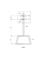
- FIG. 1 is an overall configuration diagram of a contactless charging system including a vehicle including a parking assistance device and a power feeding device according to an embodiment of the present invention.
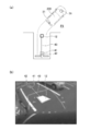
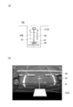
- Fig.2 (a) is a top view which shows the positional relationship of the vehicle provided with a receiving coil and the parking lot provided with a power transmission coil.
- FIG. 2B is a back camera image at the backward start position P1 shown in FIG.
- FIG. 3 is a schematic diagram showing a positional relationship between the power transmission coil and the ground mark.
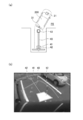
- Fig.4 (a) is a top view which shows the positional relationship of the vehicle provided with a receiving coil and the parking lot provided with a power transmission coil.
- FIG. 4B is a back camera image at the position P2 shown in FIG.
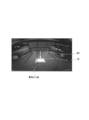
- FIG.5 (a) is a top view which shows the positional relationship of the vehicle provided with a receiving coil and the parking lot provided with a power transmission coil.
- FIG. 5B is a back camera image at the position P3 shown in FIG.
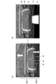
- FIG. 6A shows an image before switching displayed on the display unit.
- FIG. 6B is an image after switching to be displayed on the display unit.
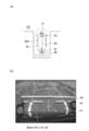
- FIG. 7 is a schematic diagram showing a positional relationship between the power transmission coil and the ground mark.
- FIG. 8A is a top view showing a positional relationship between a vehicle including a power receiving coil and a parking lot including a power transmitting coil.
- FIG. 8B is a screen of the display unit 33 indicating that the power transmission coil and the power reception coil overlap at the target parking position P4 illustrated in FIG.
- FIG. 9A and 9B are top views showing the positional relationship between a vehicle including a power receiving coil and a parking lot including a power transmitting coil.
- FIG. 10 is a diagram in which the vehicle center line is superimposed on the camera image displayed on the display unit 33.
- FIG. 11 is a flowchart for explaining the parking assist operation performed by the arithmetic processing unit according to the present embodiment.
- FIG. 1 is an overall configuration diagram of a contactless charging system 10 including a vehicle 200 including a parking assistance device and a power feeding device 100 according to an embodiment of the present invention.
- the non-contact charging system 10 includes a power feeding device 100 disposed in a power feeding stand, a parking space, and the like, and a vehicle 200, and a vehicle 200 side from a power transmission coil 12 provided in the power feeding device 100. Power is supplied to the power receiving coil 21 in a non-contact manner. More specifically, the non-contact charging system 10 transmits and receives high-frequency power between the power transmission coil 12 and the power receiving coil 21 in a non-contact state by electromagnetic induction. When voltage is applied to the power transmission coil 12, magnetic coupling occurs between the power transmission coil 12 and the power reception coil 21, and power is supplied from the power transmission coil 12 to the power reception coil 21.
- the power supply apparatus 100 includes a power control unit 11, a power transmission coil 12, a wireless communication unit 13, and a control unit 14.
- the power control unit 11 includes a rectification unit 111, a PFC circuit 112, and an inverter 113. Further, the power control unit 11 converts AC power transmitted from the AC power source 300 into high-frequency AC power and transmits the power to the power transmission coil 12.
- the rectifying unit 111 is electrically connected to the AC power supply 300 and rectifies the output AC power from the AC power supply 300.
- the PFC 112 is a circuit (Power Factor Correction) for improving the power factor by shaping the output waveform from the rectifying unit 111, and is connected between the rectifying unit 111 and the inverter 113.
- the inverter 113 is a power conversion circuit including a PWM control circuit having a switching element such as an IGBT. Specifically, the inverter 113 converts the switching element into on and off based on a detection current of a current sensor (not shown), thereby converting the switching element into high-frequency AC power and supplying it to the power transmission coil 12.
- the wireless communication unit 13 performs bidirectional communication with the wireless communication unit 25 provided in the vehicle 200.
- the control unit 14 is a part that controls the entire power supply apparatus 100, and transmits a signal to the vehicle 200 side to start power supply from the power supply apparatus 100 through communication between the wireless communication units 13 and 25. A signal indicating that the power from 100 is to be received is received from the vehicle 200 side. Further, the control unit 14 performs switching control of the inverter 113 based on a detection current of a current sensor (not shown), and controls electric power supplied to the power transmission coil 12.
- the vehicle 200 includes a power receiving coil 21, a rectifying unit 22, a relay unit 23, a battery 24, a wireless communication unit 25, a charging control unit 26, a notification unit 27, an inverter 28, a motor 29, and a front camera. 30, a back camera 31, an arithmetic processing unit 32, and a display unit 33.
- the power receiving coil 21 is a vehicle coil provided on the bottom surface of the vehicle 200.
- the power receiving coil 21 and the power transmitting coil 12 face each other with a predetermined distance. Then, when power for feeding is supplied to the power transmission coil 12, this power is transmitted to the power receiving coil 21, and the battery 24 can be charged.
- the rectifying unit 22 is connected to the power receiving coil 21 and rectifies AC power received by the power receiving coil 21 into direct current.
- the relay unit 23 includes a relay switch that is switched on and off under the control of the charging control unit 26. Further, the relay unit 23 disconnects the main circuit system including the battery 24 from the power receiving coil 21 and the rectifying unit 22 serving as a charging circuit unit by turning off the relay switch.
- the battery 24 is a power source of the vehicle 200 and is configured by connecting a plurality of secondary batteries.
- the wireless communication unit 25 performs bidirectional communication with the wireless communication unit 13 provided in the power supply apparatus 100.
- the charging control unit 26 is a controller for controlling the charging of the battery 24, and controls the relay unit 23, the wireless communication unit 25, and the notification unit 27. Specifically, the charging control unit 26 transmits a signal indicating that charging is started to the control unit 14 through communication of the wireless communication units 25 and 13. In addition, the charging control unit 26 is connected to a controller (not shown) that controls the entire vehicle 200 via a CAN communication network. This controller manages the switching control of the inverter 28 and the state of charge (SOC) of the battery 24. When the charge control unit 26 receives a signal from the controller that the battery 24 has reached full charge, the charge control unit 26 transmits a signal to the control unit 14 to end charging.
- SOC state of charge
- the notification unit 27 includes a warning lamp, a speaker, and the like, and outputs light, voice, or the like to the driver based on control by the charging control unit 26.
- the inverter 28 is a power conversion circuit including a PWM control circuit having a switching element such as an IGBT, and based on the switching control signal, the DC power output from the battery 24 is converted into AC power and supplied to the motor 29.
- the motor 29 is a drive source for driving the vehicle 200 and is, for example, a three-phase AC motor.
- the front camera 30 photographs the front periphery of the vehicle 200.
- the back camera 31 (imaging means) captures the rear periphery of the vehicle 200.
- These cameras are cameras having imaging elements such as a CCD and a CMOS, for example, which continuously take pictures in time and output the taken images.
- the arithmetic processing unit 32 (control means) is configured as an integrated computer including storage means such as a CPU, RAM, ROM, and hard disk.
- the arithmetic processing unit 32 can capture images captured by the front camera 30 and the back camera 31 and execute predetermined image processing, or can perform display control for switching information displayed on the display unit 33.
- the display unit 33 displays various information to the driver, and is a display of a navigation system, for example.
- the display unit 33 can display images from the front camera 30 and the back camera 31.
- the target parking position P4 is a parking position shown in FIG.
- FIG. 2B is an image of the back camera 31 of the vehicle 200 at the reverse start position P1 shown in FIG. This video is displayed on the display unit 33 shown in FIG. As shown in FIG. 2B, the power transmission coil 12, the ground marks 41 and 42, and the power transmission cable 43 are displayed on the video of the back camera 31. Note that FIG. 2B is an image taken by the back camera 31 at the same time as the video of the back camera 31.
- the ground marks 41 and 42 are marks provided on the road surface of the parking lot provided with the power transmission coil 12.
- the power transmission cable 43 is a cable that supplies power to the power transmission coil 12, and is provided on a road surface of a parking lot that includes the power transmission coil 12.
- the power transmission cable 43 is covered for safety.
- the arithmetic processing unit 32 shown in FIG. 1 takes the power transmission coil 12 and ground marks 41, 42 taken by the back camera 31 shown in FIG. And the distance between the power transmission coil 12 and the ground mark 41 and the distance between the ground mark 41 and the ground mark 42 are calculated. Note that an image in which the power transmission coil 12 and the ground marks 41 and 42 are simultaneously shown is referred to as a “parking initial image”.
- FIG. 3 is a schematic diagram showing the positional relationship between the power transmission coil 12, the ground marks 41 and 42, and the power transmission cable 43 taken by the back camera 31 shown in FIG.
- Point A is the center point of the ground mark 41.
- Point B is the center point of the ground mark 42.
- the power transmission cable 43 is arranged on a straight line connecting the points A and B.
- the center line L1 of the power transmission cable 43 passes through the center of the power transmission coil 12.
- the distance a1 is the distance between the ground mark 41 and the ground mark 42.
- the distance a2 is the distance between the ground mark 41 and the power transmission coil 12.
- the distance a3 is the length of the power transmission coil 12 in the vehicle front-rear direction.
- the arithmetic processing unit 32 When a parking initial image is captured by the back camera 31, the arithmetic processing unit 32 performs predetermined image processing on the captured parking initial image and calculates distances a1, a2, and a3.
- the ground mark of this embodiment is a square shape, as long as the distance with the power transmission coil 12 is computable, what kind of shape may be sufficient as it. In the present embodiment, two ground marks are used, but the number of ground marks is not limited to this. For example, the distance between the upper end and the lower end of this large ground mark may be calculated using one large ground mark, and this distance may be used instead of the distance a1.
- FIG. 4A is a top view showing the positional relationship between the vehicle 200 and the parking lot provided with the power transmission coil 12 when moving backward from the reverse start position P1 shown in FIG. 2A to the position P2. It is.
- FIG. 4B is an image of the back camera 31 of the vehicle 200 at the position P2 shown in FIG.
- the power transmission coil 12 and the ground marks 41 and 42 are simultaneously shown on the back camera 31.
- the arithmetic processing unit 32 overwrites and updates the parking initial image every time it is photographed. Then, the arithmetic processing unit 32 performs predetermined image processing on the updated parking initial image, and calculates distances a1, a2, and a3 shown in FIG.
- the reason for updating the parking initial image is that the distances a1, a2, and a3 that are more accurate can be calculated as the distance from the back camera 31 to the power transmission coil 12 and the ground marks 41 and 42 is shorter. .
- FIG. 5B is an image of the back camera 31 of the vehicle 200 at the position P3 shown in FIG. Since the power transmission coil 12 has entered the lower part of the vehicle 200, it is not reflected in the back camera 31.
- the dotted line shown in FIG. 5B is a screen switching trigger line.
- the screen switching trigger line is a line used for switching the image displayed on the display unit 33. Specifically, the screen switching trigger line is set so as to reach the ground mark 41 when the distance between the vehicle 200 and the target parking position P4 becomes smaller than a predetermined value.
- the arithmetic processing unit 32 switches the screen of the display unit 33 when the screen switching trigger line reaches the ground mark 41 as shown in FIG.
- the setting of the screen switching trigger line can be appropriately changed according to the size of the vehicle 200, the position of the power receiving coil 21 provided in the vehicle 200, the position of the power transmitting coil 12 provided in the parking lot, and the like.
- the screen switching trigger line is a non-display line that is not displayed on the display unit 33.
- FIG. 6A is a screen before switching the screen displayed on the display unit 33, and is the same screen as FIG. 5B.
- FIG. 6B is a screen after the screen displayed on the display unit 33 is switched.
- the arithmetic processing unit 32 moves the region R1 shown in FIG. 6A to the upper side of the screen and further expands the display range of the region R2. To do.
- the arithmetic processing part 32 displays the power transmission coil 12 on the screen after switching.
- FIG. 7 shows the ground marks 41 and 42 displayed on the screen before switching shown in FIG. 6A, and the power transmission coil 12 and the power transmission cable 43 estimated based on the ground marks 41 and 42 and the initial parking image. It is a schematic diagram which shows these positional relationships. That is, in FIG. 7, the part surrounded by the alternate long and short dash line is a part reflected on the back camera 31 before the screen is switched, and the other part is an estimated part.
- the ground mark 41 and the ground mark are displayed. 42 will be shown at the same time.
- an image in which the ground marks 41 and 42 are simultaneously shown is referred to as a “parking end image”.
- the arithmetic processing unit 32 performs predetermined image processing on the final parking image, and calculates a distance b1 between the ground mark 41 and the ground mark 42. If this distance b1 and the distance a1 shown in FIG. 3 are used, the ratio of the distance a1 to the distance b1 can be obtained.
- the distance b2 between the ground mark 41 and the power transmission coil 12 and the distance b3 in the vehicle longitudinal direction of the power transmission coil 12 shown in FIG. 7 are obtained from the distances a2 and a3 of the initial parking image shown in FIG. be able to.
- the arithmetic processing unit 32 can estimate the position of the power transmission coil 12 by performing such processing. Then, based on the estimated position of the power transmission coil 12, the arithmetic processing unit 32 can display the power transmission coil 12 in a shape almost similar to the real thing on the screen after switching as shown in FIG. 6B. By displaying in this way, the driver can grasp the power transmission coil 12 that cannot be seen with the back camera 31 as if the vehicle 200 became transparent.
- the arithmetic processing unit 32 superimposes and displays the power receiving coil 21 provided in the vehicle 200 on the screen after switching.
- the displayed power receiving coil 21 is a symbol schematically showing its shape. The position of the power receiving coil 21 can be acquired in advance.
- the positional relationship between the power transmitting coil 12 and the power receiving coil 21 shown in FIG. 6B is the positional relationship between the power transmitting coil 12 and the power receiving coil 21 shown in FIG.
- the power transmission coil 12 and the power reception coil 21 partially overlap each other, and as shown in FIG. 6B, the driver can grasp the overlapping state at a glance.
- Fig.8 (a) when it advances backward to the target parking position P4, only the movement of the receiving coil 21 is displayed on the screen after switching. That is, after the screen is switched, the screen background and the power receiving coil 21 are not changed, and only the power receiving coil 21 is moved.
- FIG. 8B is a screen of the display unit 33 indicating that the power transmission coil and the power reception coil overlap at the target parking position P4 illustrated in FIG. Comparing FIG. 6B and FIG. 8B, it can be seen that only the receiving coil 21 is moving. In this way, by displaying only the movement of the power receiving coil 21 on the screen after switching, the driver sees only the power receiving coil 21 that moves in accordance with the movement of the vehicle 200, and the power transmission coil 12 and the power receiving coil 21. Therefore, the positioning of the power transmission coil 12 and the power receiving coil 21 can be performed with high accuracy.
- the arithmetic processing unit 32 switches the screen displayed on the display unit 33.
- the arithmetic processing unit 32 displays the power transmission coil 12 in a shape almost similar to the real thing on the screen after switching, and further superimposes and displays a symbol schematically indicating the power reception coil 21.
- the arithmetic processing unit 32 moves only the power receiving coil 21 in accordance with the movement of the vehicle 200. In this way, the parking assistance device of the present embodiment supports the alignment of the power transmission coil 12 and the power reception coil 21.
- the alignment support between the power transmission coil 12 and the power reception coil 21 in reverse parking has been described, but the parking support device of the present invention can also be applied to front parking and parallel parking.
- alignment support similar to that of the present embodiment can be performed using the image of the front camera 30.
- FIG. 9B the same alignment support can be performed when the power transmission coil 12, the power reception coil 21, and the ground marks 41 and 42 are different.
- the driver can park the vehicle center line while aligning the vehicle center line with the center of the power transmitting coil 12, so that the power receiving coil 12 can easily receive power.
- the alignment with the coil 21 can be performed.
- the center line of the power receiving coil 21 in the vehicle width direction does not coincide with the vehicle center line
- the line displayed on the display unit 33 can be changed from the vehicle center line to the coil center line.
- a timing for displaying the vehicle center line for example, when the screen is switched, the vehicle center line can be displayed.
- an image representing the body frame of the vehicle 200 may be superimposed and displayed on the screen after switching.
- the driver can perform alignment between the power transmission coil 12 and the power reception coil 21 while looking at the power transmission coil 12, the power reception coil 21, and the vehicle body frame. It can be carried out.
- the degree of overlap between the power transmission coil 12 and the power reception coil 21 is displayed with a number of 0 to 100% on the screen after switching to notify the driver. Good.
- the screen when it is detected that an obstacle is approaching the vehicle 200 using a proximity sensor during driving after switching the screen, the screen may be restored. Since the background image does not change on the screen after switching, the driver cannot grasp the state behind the vehicle from the display unit 33. However, by returning the screen in this way, the driver is cautioned. Can do.
- the driver can concentrate on parking until the screen is switched. In other words, by delaying screen switching, it is possible to prevent the driver's attention from concentrating on the coil alignment and to reduce the possibility of contact with an obstacle or the like.
- step S101 the arithmetic processing unit 32 determines whether or not the shift range is R (reverse range). If the shift range is the reverse range, the process proceeds to step S103. If the shift range is not the reverse range, the process proceeds to step S102.
- step S102 the arithmetic processing unit 32 determines whether or not a PA (parking assist) switch is on.
- the parking assist switch is a switch for displaying the image of the front camera 30 on the display unit 33.
- the parking assist switch may be a hard switch provided in the passenger compartment or a soft switch on the display unit 33. If the parking assist switch is on, the process proceeds to step S104. If the PA switch is off, wait.
- step S103 the arithmetic processing unit 32 displays the video (back view) of the back camera 31 on the display unit 33.
- step S104 the arithmetic processing unit 32 displays the video (front view) of the front camera 30 on the display unit 33.
- step S105 the arithmetic processing unit 32 determines whether or not the relative distance between the power transmission coil 12 and the ground mark 41 and the ground mark 41 and the ground mark 42 can be measured.
- the relative distance between the power transmission coil 12 and the ground mark 41 and between the ground mark 41 and the ground mark 42 can be measured, that is, when the power transmission coil 12 and the ground marks 41 and 42 are simultaneously displayed on the back camera 31 or the front camera 30.
- the process proceeds to step S106.
- the process returns to step S105.
- step S ⁇ b> 106 the arithmetic processing unit 32 photographs the power transmission coil 12 and the ground marks 41 and 42 using the front camera 30 or the back camera 31.
- the image photographed at this time is a parking initial image.
- step S107 the arithmetic processing unit 32 determines whether or not the ground marks 41 and 42 can be seen simultaneously when the power transmission coil 12 reaches the lower end of the screen of the front camera 30 or the back camera 31. If the ground marks 41 and 42 can be seen simultaneously when the power transmission coil 12 reaches the lower end of the screen of the front camera 30 or the back camera 31, the process proceeds to step S108. When the power transmission coil 12 reaches the lower end of the screen of the front camera 30 or the back camera 31, if the ground marks 41 and 42 cannot be seen at the same time, the process proceeds to step S109.
- step S108 the arithmetic processing unit 32 uses the front camera 30 or the back camera 31 to capture the power transmission coil 12 and the ground marks 41 and 42, and overwrites and updates the previously captured parking initial image.
- step S109 the arithmetic processing unit 32 determines whether or not the ground mark 41 has reached the screen switching trigger line.
- the process proceeds to step S110. If the ground mark 41 has not reached the screen switching trigger line, the process returns to step S109.
- the arithmetic processing unit 32 uses the front camera 30 or the back camera 31 to acquire an image in which the ground marks 41 and 42 are simultaneously reflected. This image is a parking end image.
- step S110 the arithmetic processing unit 32 determines whether or not the vehicle 200 is straight with respect to the parking frame. In other words, it is whether or not the ground marks 41 and 42 displayed on the display unit 33 are arranged vertically with respect to the display unit 33. If the vehicle 200 is straight with respect to the parking frame, the process proceeds to step S112. If the vehicle 200 is not straight with respect to the parking frame, the process proceeds to step S111.
- step S111 the arithmetic processing unit 32 corrects the parking frame image so that the ground marks 41 and 42 are aligned vertically with respect to the parking frame image. Thereby, the driver can be notified that the vehicle 200 is bent with respect to the parking frame.
- step S112 the arithmetic processing unit 32 switches the screen of the display unit 33, and displays the power transmission coil 12 in a shape almost similar to the real thing on the screen after switching based on the parking initial image and the parking end image.
- step S113 the arithmetic processing unit 32 displays the power receiving coil 21 provided in the vehicle 200 superimposed on the screen after switching as a symbol schematically showing its shape.
- step S114 the arithmetic processing unit 32 determines whether or not the shift range is P (parking range). When the shift range is the parking range, the series of processes is terminated. If the shift range is not the parking range, the process returns to step S114.
- the parking assist device of the present embodiment switches the screen of the display unit 33 when the power transmission coil 12 is not reflected on the back camera 31 or the front camera 30.
- the parking assist device estimates the position of the power transmission coil 12 based on the initial parking image and the parking end image, and displays the power transmission coil 12 on the display unit 33 in a form close to the real thing.
- the parking assistance device displays the power receiving coil 21 provided in the vehicle 200 on the screen after switching as a symbol schematically showing its shape.
- a parking assistance apparatus displays only the movement of the receiving coil 21 in the screen after switching. Thereby, the driver can understand the positional relationship between the power transmission coil 12 and the power reception coil 21 at a glance, and can perform highly accurate alignment.
- the parking assistance apparatus of this embodiment displays the vehicle center line with respect to the vehicle width direction on the display unit 33. Therefore, since the driver can park the vehicle center line while aligning the vehicle center line with the center of the power transmission coil 12, the driver can easily align the power transmission coil 12 and the power reception coil 21.
- Power transmission coil 21 Power reception coil (coil for vehicle) 30, 31 Camera (photographing means) 32 arithmetic processing unit (control means) 33 Display section (display means) 41, 42 Ground mark
Abstract
Description
図1は、本発明の実施形態に係る駐車支援装置を含む車両200及び給電装置100を備えた非接触充電システム10の全体構成図である。 Hereinafter, embodiments of the present invention will be described with reference to the drawings.
FIG. 1 is an overall configuration diagram of a
電力制御部11は、整流部111と、PFC回路112と、インバータ113と、を備える。また、電力制御部11は、交流電源300から送電される交流電力を、高周波の交流電力に変換し、送電コイル12に電力を送電する。 The
The
制御部14は、給電装置100全体を制御する部分であり、無線通信部13,25間の通信により給電装置100からの電力供給を開始する旨の信号を車両200側に送信したり、給電装置100からの電力を受給したい旨の信号を車両200側から受信したりする。また、制御部14は、電流センサ(図示せず)の検出電流に基づいてインバータ113のスイッチング制御を行い、送電コイル12に供給する電力を制御する。 The
The
無線通信部25は、給電装置100に設けられた無線通信部13と双方向に通信を行う。 The
The
モータ29は、車両200を駆動させるための駆動源であり、例えば三相の交流電動機である。 The
The
図4(a)は、図2(a)に示す後退開始位置P1から、後退を進めて、位置P2に来たときの車両200と送電コイル12を備える駐車場との位置関係を示す上面図である。図4(b)は、図4(a)に示す位置P2における車両200のバックカメラ31の映像である。 Next, the update of the parking initial image will be described with reference to FIG.
FIG. 4A is a top view showing the positional relationship between the
図6(a)は、表示部33に表示される画面を切り替える前の画面であり、図5(b)と同じ画面である。図6(b)は、表示部33に表示される画面を切り替えた後の画面である。図5(b)に示す画面切り替えトリガー線が地上マーク41に到達すると、演算処理部32は、図6(a)に示す領域R1を画面の上側に移動し、さらに領域R2の表示範囲を拡大する。そして、演算処理部32は、切り替え後の画面に送電コイル12を表示する。 Next, switching of the screen displayed on the display unit 33 will be described with reference to FIG.
FIG. 6A is a screen before switching the screen displayed on the display unit 33, and is the same screen as FIG. 5B. FIG. 6B is a screen after the screen displayed on the display unit 33 is switched. When the screen switching trigger line shown in FIG. 5B reaches the
図7は、図6(a)に示す切り替え前の画面に表示される地上マーク41,42と、この地上マーク41,42と駐車初期画像とに基づいて推定される送電コイル12と送電ケーブル43の位置関係を示す模式図である。すなわち、図7において、一点鎖線で囲われた部分が画面切り替え前にバックカメラ31に映る部分であり、その他の部分は、推定する部分である。 Here, a method for displaying the
FIG. 7 shows the ground marks 41 and 42 displayed on the screen before switching shown in FIG. 6A, and the
車両中心線を表示するタイミングとして、例えば画面を切り替えた際に車両中心線を表示することができる。 Furthermore, in this embodiment, you may display the vehicle centerline with respect to a vehicle width direction on the display part 33, as shown in FIG. When the center line of the
As a timing for displaying the vehicle center line, for example, when the screen is switched, the vehicle center line can be displayed.
21 受電コイル(車両用コイル)
30、31 カメラ(撮影手段)
32 演算処理部(制御手段)
33 表示部(表示手段)
41、42 地上マーク 12
30, 31 Camera (photographing means)
32 arithmetic processing unit (control means)
33 Display section (display means)
41, 42 Ground mark
Claims (3)
- 車両に搭載され、前記車両の周囲を撮影することが可能な撮影手段と、
前記車両の底面に設けられた車両用コイルと、
前記撮影手段で撮影された画像を表示する表示手段と、
前記表示手段の表示制御を行なう制御手段とを備え、
前記制御手段は、前記撮影手段が撮影した駐車スペースの路面に設置された送電コイルと、この送電コイルから所定距離離れて設置された地上マークとが同時に映る駐車初期画像を記録し、前記車両と目標駐車位置との距離が所定値よりも小さくなった際に、前記撮影手段によって撮影される前記地上マークと前記駐車初期画像とに基づいて前記送電コイルを前記表示手段に表示し、かつ、前記車両用コイルを示す画像を前記表示手段に重畳して表示することを特徴とする駐車支援装置。 A photographing means mounted on a vehicle and capable of photographing the surroundings of the vehicle;
A vehicle coil provided on the bottom surface of the vehicle;
Display means for displaying an image photographed by the photographing means;
Control means for performing display control of the display means,
The control means records a parking initial image in which a power transmission coil installed on a road surface of a parking space photographed by the photographing means and a ground mark installed at a predetermined distance from the power transmission coil are recorded, and the vehicle When the distance to the target parking position becomes smaller than a predetermined value, the power transmission coil is displayed on the display means based on the ground mark and the parking initial image photographed by the photographing means, and the The parking assistance apparatus characterized by superimposing and displaying the image which shows the coil for vehicles on the said display means. - 前記制御手段は、前記車両用コイルの車幅方向の対する中心線を前記表示手段に重畳して表示することを特徴とする請求項1に記載の駐車支援装置。 The parking assist device according to claim 1, wherein the control means displays a center line of the vehicle coil in the vehicle width direction so as to be superimposed on the display means.
- 駐車スペースの路面に設置された送電コイルと、この送電コイルから所定距離離れて設置された地上マークとが同時に映る駐車初期画像を撮影し、
車両と目標駐車位置との距離が所定値よりも小さくなった際に撮影した前記地上マークと前記駐車初期画像とに基づいて前記送電コイルを表示し、かつ、前記車両の底面に設けられた車両用コイルを示す画像を重畳して表示することを特徴とする駐車支援方法。 Shooting an initial parking image in which a power transmission coil installed on the road surface of the parking space and a ground mark installed at a predetermined distance from the power transmission coil are reflected,
The power transmission coil is displayed based on the ground mark and the parking initial image taken when the distance between the vehicle and the target parking position is smaller than a predetermined value, and the vehicle is provided on the bottom surface of the vehicle. The parking assistance method characterized by superimposing and displaying the image which shows the coil for a vehicle.
Priority Applications (6)
| Application Number | Priority Date | Filing Date | Title |
|---|---|---|---|
| KR1020167018248A KR101860245B1 (en) | 2014-01-30 | 2014-01-30 | Parking assistance device and parking assistance method |
| EP14881278.7A EP3100899B1 (en) | 2014-01-30 | 2014-01-30 | Parking assistance device and parking assistance method |
| US15/114,313 US9975488B2 (en) | 2014-01-30 | 2014-01-30 | Parking assistance device and parking assistance method |
| PCT/JP2014/052107 WO2015114775A1 (en) | 2014-01-30 | 2014-01-30 | Parking assistance device and parking assistance method |
| CN201480073935.0A CN106414154B (en) | 2014-01-30 | 2014-01-30 | Parking aid and parking assistance method |
| JP2015559672A JP6160713B2 (en) | 2014-01-30 | 2014-01-30 | Parking assistance device and parking assistance method |
Applications Claiming Priority (1)
| Application Number | Priority Date | Filing Date | Title |
|---|---|---|---|
| PCT/JP2014/052107 WO2015114775A1 (en) | 2014-01-30 | 2014-01-30 | Parking assistance device and parking assistance method |
Publications (1)
| Publication Number | Publication Date |
|---|---|
| WO2015114775A1 true WO2015114775A1 (en) | 2015-08-06 |
Family
ID=53756387
Family Applications (1)
| Application Number | Title | Priority Date | Filing Date |
|---|---|---|---|
| PCT/JP2014/052107 WO2015114775A1 (en) | 2014-01-30 | 2014-01-30 | Parking assistance device and parking assistance method |
Country Status (6)
| Country | Link |
|---|---|
| US (1) | US9975488B2 (en) |
| EP (1) | EP3100899B1 (en) |
| JP (1) | JP6160713B2 (en) |
| KR (1) | KR101860245B1 (en) |
| CN (1) | CN106414154B (en) |
| WO (1) | WO2015114775A1 (en) |
Cited By (8)
| Publication number | Priority date | Publication date | Assignee | Title |
|---|---|---|---|---|
| JP2016197989A (en) * | 2013-04-02 | 2016-11-24 | パイオニア株式会社 | Driving operation assist device and driving operation assist method |
| CN107021012A (en) * | 2016-01-30 | 2017-08-08 | 深圳市泰金田科技有限公司 | Electric car reverse aid, system and reversing auxiliary alignment methods |
| CN107651013A (en) * | 2016-07-25 | 2018-02-02 | 奥迪股份公司 | Parking assisting system and method for electric vehicle |
| EP3333113A1 (en) * | 2016-12-07 | 2018-06-13 | Cargotec Patenter AB | A vehicle, and a method for a vehicle, including target marker on an overview image |
| EP3459783A4 (en) * | 2016-05-18 | 2019-05-22 | Nissan Motor Co., Ltd. | Parking assist method and parking assist device |
| US10391938B2 (en) * | 2015-05-15 | 2019-08-27 | Ford Global Technologies, Llc | Imaging system for locating a moving object in relation to another object |
| US10486549B2 (en) * | 2015-05-15 | 2019-11-26 | Ford Global Technologies, Llc | Parking assist overlay |
| US10576892B2 (en) | 2016-03-24 | 2020-03-03 | Ford Global Technologies, Llc | System and method for generating a hybrid camera view in a vehicle |
Families Citing this family (13)
| Publication number | Priority date | Publication date | Assignee | Title |
|---|---|---|---|---|
| DE102014018674A1 (en) * | 2014-12-13 | 2016-06-16 | Daimler Ag | Method for charging an energy store in a motor vehicle with ready signalization and charging system |
| RU2652719C1 (en) * | 2015-01-29 | 2018-04-28 | Ниссан Мотор Ко., Лтд. | Parking assistance system and parking assistance method |
| MX2017012467A (en) * | 2015-04-07 | 2018-01-30 | Nissan Motor | Parking assistance system and parking assistance device. |
| US20190266416A1 (en) * | 2015-11-08 | 2019-08-29 | Otobrite Electronics Inc. | Vehicle image system and method for positioning vehicle using vehicle image |
| DE102017206530A1 (en) * | 2017-04-18 | 2018-10-18 | Bayerische Motoren Werke Aktiengesellschaft | Vehicle positioning for inductive energy transmission |
| CA3067176C (en) * | 2017-06-13 | 2023-04-04 | Nissan Motor Co., Ltd. | Method for controlling non-contact electric power supply system, and non-contact electric power supply system |
| EP3650315B1 (en) * | 2017-07-07 | 2021-01-20 | Nissan Motor Co., Ltd. | Parking assistance method and parking assistance device |
| DE102017216712A1 (en) * | 2017-09-21 | 2019-03-21 | Siemens Mobility GmbH | Recording and optimizing the breakpoint accuracy of a vehicle |
| JP7024312B2 (en) * | 2017-10-19 | 2022-02-24 | 株式会社Ihi | Coil device |
| US10380440B1 (en) | 2018-10-23 | 2019-08-13 | Capital One Services, Llc | Method for determining correct scanning distance using augmented reality and machine learning models |
| JP2020078146A (en) * | 2018-11-07 | 2020-05-21 | トヨタ自動車株式会社 | Electric vehicle |
| CN110920510A (en) * | 2019-11-25 | 2020-03-27 | 浙江合众新能源汽车有限公司 | System and method for indicating parking standby by using vehicle lamp of vehicle |
| US20230302946A1 (en) * | 2021-11-24 | 2023-09-28 | Volta Charging, Llc | Systems and methods for collision detection using an electric vehicle charging station |
Citations (8)
| Publication number | Priority date | Publication date | Assignee | Title |
|---|---|---|---|---|
| JP2006327498A (en) * | 2005-05-27 | 2006-12-07 | Aisin Aw Co Ltd | Parking support method and parking support device |
| JP2010226945A (en) * | 2009-02-25 | 2010-10-07 | Maspro Denkoh Corp | Power supply system of mobile unit |
| JP2010234878A (en) * | 2009-03-30 | 2010-10-21 | Aisin Aw Co Ltd | Power receiving guide device, power receiving guide method and power receiving guide program |
| JP2011015549A (en) | 2009-07-02 | 2011-01-20 | Toyota Motor Corp | Parking support system, and method of controlling the same |
| JP2011182608A (en) * | 2010-03-03 | 2011-09-15 | Honda Motor Co Ltd | Electric vehicle |
| JP2012175764A (en) * | 2011-02-18 | 2012-09-10 | Honda Motor Co Ltd | Electric vehicle |
| WO2013146139A1 (en) * | 2012-03-28 | 2013-10-03 | 日産自動車株式会社 | Parking assistance system and parking assistance method |
| JP2013236524A (en) * | 2012-05-11 | 2013-11-21 | Mitsubishi Electric Corp | Non-contact power feeding system |
Family Cites Families (9)
| Publication number | Priority date | Publication date | Assignee | Title |
|---|---|---|---|---|
| JP4222355B2 (en) * | 2005-09-29 | 2009-02-12 | トヨタ自動車株式会社 | PARKING ASSISTANCE DEVICE AND POWER TRANSFER METHOD BETWEEN VEHICLE AND GROUND EQUIPMENT |
| JP5136256B2 (en) | 2008-07-18 | 2013-02-06 | 日産自動車株式会社 | Parking assist device and image display method |
| EP2735083A4 (en) | 2011-07-21 | 2015-10-07 | Ut Battelle Llc | Wireless power transfer electric vehicle supply equipment installation and validation tool |
| FR2981626B1 (en) | 2011-10-19 | 2013-12-20 | Peugeot Citroen Automobiles Sa | METHOD FOR ASSISTING POSITIONING OF AN ELECTRIC OR HYBRID VEHICLE |
| JP5845921B2 (en) * | 2012-01-24 | 2016-01-20 | 株式会社Ihi | Mobile vehicle power supply system |
| JP6065394B2 (en) * | 2012-03-14 | 2017-01-25 | 株式会社Ihi | Mobile vehicle power supply system and mobile vehicle |
| CN202923500U (en) * | 2012-11-27 | 2013-05-08 | 德尔福电子(苏州)有限公司 | Wireless charging guide system of electric vehicle |
| JP6110758B2 (en) * | 2013-08-26 | 2017-04-05 | 本田技研工業株式会社 | Vehicle guidance device |
| US9463707B2 (en) * | 2014-12-05 | 2016-10-11 | Hyundai America Technical Center, Inc. | Method and system for aligning a vehicle with a wireless charging assembly |
-
2014
- 2014-01-30 WO PCT/JP2014/052107 patent/WO2015114775A1/en active Application Filing
- 2014-01-30 EP EP14881278.7A patent/EP3100899B1/en active Active
- 2014-01-30 US US15/114,313 patent/US9975488B2/en active Active
- 2014-01-30 CN CN201480073935.0A patent/CN106414154B/en active Active
- 2014-01-30 KR KR1020167018248A patent/KR101860245B1/en active IP Right Grant
- 2014-01-30 JP JP2015559672A patent/JP6160713B2/en active Active
Patent Citations (8)
| Publication number | Priority date | Publication date | Assignee | Title |
|---|---|---|---|---|
| JP2006327498A (en) * | 2005-05-27 | 2006-12-07 | Aisin Aw Co Ltd | Parking support method and parking support device |
| JP2010226945A (en) * | 2009-02-25 | 2010-10-07 | Maspro Denkoh Corp | Power supply system of mobile unit |
| JP2010234878A (en) * | 2009-03-30 | 2010-10-21 | Aisin Aw Co Ltd | Power receiving guide device, power receiving guide method and power receiving guide program |
| JP2011015549A (en) | 2009-07-02 | 2011-01-20 | Toyota Motor Corp | Parking support system, and method of controlling the same |
| JP2011182608A (en) * | 2010-03-03 | 2011-09-15 | Honda Motor Co Ltd | Electric vehicle |
| JP2012175764A (en) * | 2011-02-18 | 2012-09-10 | Honda Motor Co Ltd | Electric vehicle |
| WO2013146139A1 (en) * | 2012-03-28 | 2013-10-03 | 日産自動車株式会社 | Parking assistance system and parking assistance method |
| JP2013236524A (en) * | 2012-05-11 | 2013-11-21 | Mitsubishi Electric Corp | Non-contact power feeding system |
Non-Patent Citations (1)
| Title |
|---|
| See also references of EP3100899A4 |
Cited By (10)
| Publication number | Priority date | Publication date | Assignee | Title |
|---|---|---|---|---|
| JP2016197989A (en) * | 2013-04-02 | 2016-11-24 | パイオニア株式会社 | Driving operation assist device and driving operation assist method |
| US10391938B2 (en) * | 2015-05-15 | 2019-08-27 | Ford Global Technologies, Llc | Imaging system for locating a moving object in relation to another object |
| US10486549B2 (en) * | 2015-05-15 | 2019-11-26 | Ford Global Technologies, Llc | Parking assist overlay |
| CN107021012A (en) * | 2016-01-30 | 2017-08-08 | 深圳市泰金田科技有限公司 | Electric car reverse aid, system and reversing auxiliary alignment methods |
| US10576892B2 (en) | 2016-03-24 | 2020-03-03 | Ford Global Technologies, Llc | System and method for generating a hybrid camera view in a vehicle |
| EP3459783A4 (en) * | 2016-05-18 | 2019-05-22 | Nissan Motor Co., Ltd. | Parking assist method and parking assist device |
| US10967745B2 (en) | 2016-05-18 | 2021-04-06 | Nissan Motor Co., Ltd. | Parking assistance method and parking assistance device |
| CN107651013A (en) * | 2016-07-25 | 2018-02-02 | 奥迪股份公司 | Parking assisting system and method for electric vehicle |
| EP3333113A1 (en) * | 2016-12-07 | 2018-06-13 | Cargotec Patenter AB | A vehicle, and a method for a vehicle, including target marker on an overview image |
| WO2018103928A1 (en) * | 2016-12-07 | 2018-06-14 | Cargotec Patenter Ab | A vehicle, and a method for a vehicle, including target marker on an overview image |
Also Published As
| Publication number | Publication date |
|---|---|
| KR20160096161A (en) | 2016-08-12 |
| JPWO2015114775A1 (en) | 2017-03-23 |
| EP3100899B1 (en) | 2022-04-27 |
| JP6160713B2 (en) | 2017-07-12 |
| US9975488B2 (en) | 2018-05-22 |
| CN106414154A (en) | 2017-02-15 |
| EP3100899A4 (en) | 2017-03-22 |
| US20170001563A1 (en) | 2017-01-05 |
| KR101860245B1 (en) | 2018-05-21 |
| CN106414154B (en) | 2019-01-04 |
| EP3100899A1 (en) | 2016-12-07 |
Similar Documents
| Publication | Publication Date | Title |
|---|---|---|
| JP6160713B2 (en) | Parking assistance device and parking assistance method | |
| US9956914B2 (en) | Parking assistance device and parking assistance method | |
| JP5751383B2 (en) | Parking support system and parking support method | |
| JP6774938B2 (en) | Parking support system and parking support device | |
| CA3024825C (en) | Parking assistance method and parking assistance device | |
| JP5377119B2 (en) | Parking support system and control method for parking support system | |
| JP5761159B2 (en) | Driving support device and driving support method | |
| JP5010715B2 (en) | Vehicle parking assist device and electric vehicle including the same | |
| JP6119868B2 (en) | Non-contact power feeding device and parking assist device | |
| WO2011132271A1 (en) | Vehicle parking assistance device and electric vehicle equipped with same | |
| WO2014192136A1 (en) | Vehicle power feeding system | |
| JP2017093155A (en) | Parking support system | |
| WO2014054608A1 (en) | Noncontact power supply device | |
| JP2012076518A (en) | Vehicle controller |
Legal Events
| Date | Code | Title | Description |
|---|---|---|---|
| 121 | Ep: the epo has been informed by wipo that ep was designated in this application |
Ref document number: 14881278 Country of ref document: EP Kind code of ref document: A1 |
|
| ENP | Entry into the national phase |
Ref document number: 2015559672 Country of ref document: JP Kind code of ref document: A |
|
| ENP | Entry into the national phase |
Ref document number: 20167018248 Country of ref document: KR Kind code of ref document: A |
|
| WWE | Wipo information: entry into national phase |
Ref document number: 15114313 Country of ref document: US |
|
| NENP | Non-entry into the national phase |
Ref country code: DE |
|
| REEP | Request for entry into the european phase |
Ref document number: 2014881278 Country of ref document: EP |
|
| WWE | Wipo information: entry into national phase |
Ref document number: 2014881278 Country of ref document: EP |