WO2015101430A1 - A cooling device comprising a flap cover - Google Patents
A cooling device comprising a flap cover Download PDFInfo
- Publication number
- WO2015101430A1 WO2015101430A1 PCT/EP2014/073291 EP2014073291W WO2015101430A1 WO 2015101430 A1 WO2015101430 A1 WO 2015101430A1 EP 2014073291 W EP2014073291 W EP 2014073291W WO 2015101430 A1 WO2015101430 A1 WO 2015101430A1
- Authority
- WO
- WIPO (PCT)
- Prior art keywords
- cover
- hinge
- cooling device
- pin
- disposed
- Prior art date
- Legal status (The legal status is an assumption and is not a legal conclusion. Google has not performed a legal analysis and makes no representation as to the accuracy of the status listed.)
- Ceased
Links
Images




Classifications
-
- F—MECHANICAL ENGINEERING; LIGHTING; HEATING; WEAPONS; BLASTING
- F25—REFRIGERATION OR COOLING; COMBINED HEATING AND REFRIGERATION SYSTEMS; HEAT PUMP SYSTEMS; MANUFACTURE OR STORAGE OF ICE; LIQUEFACTION SOLIDIFICATION OF GASES
- F25D—REFRIGERATORS; COLD ROOMS; ICE-BOXES; COOLING OR FREEZING APPARATUS NOT OTHERWISE PROVIDED FOR
- F25D23/00—General constructional features
- F25D23/02—Doors; Covers
- F25D23/025—Secondary closures
-
- F—MECHANICAL ENGINEERING; LIGHTING; HEATING; WEAPONS; BLASTING
- F25—REFRIGERATION OR COOLING; COMBINED HEATING AND REFRIGERATION SYSTEMS; HEAT PUMP SYSTEMS; MANUFACTURE OR STORAGE OF ICE; LIQUEFACTION SOLIDIFICATION OF GASES
- F25D—REFRIGERATORS; COLD ROOMS; ICE-BOXES; COOLING OR FREEZING APPARATUS NOT OTHERWISE PROVIDED FOR
- F25D2323/00—General constructional features not provided for in other groups of this subclass
- F25D2323/02—Details of doors or covers not otherwise covered
- F25D2323/024—Door hinges
Definitions
- the mouth of the housing is designed to be narrower than the pin; however, in this case, the user must apply excessive force in order to fit the pin into the housing and dislodge the pin from the housing.
- the pins used in securing the cover may break in the case the user accidentally closes the door while the cover is open.
- the cover is enabled to be kept fixed in different positions. While enabling the cover to be kept in the open position, the protrusion allows the cover to be closed by dislodging when the door is closed when the cover is open. Moreover, by means of the gripper that is positioned on the hinge so as to hold the protrusion when the cover is in the closed position, the cover is enabled to be kept as if it is locked in the closed position.
- the grippers are positioned on the hinge so that the mouths thereof face opposite directions.
- the cover is enabled to operate in a robust manner during opening/closing.
- the hinge is furthermore configured to allow the pin to be seated therein.
- no additional connection member is required to secure the pin to the body and no housing is required to be bored on the body, and the cover is secured by the hinge that is used for supporting the cover in different positions.
- a cavity wherein the hinge is seated is disposed on the body.
- the hinge is attached to the body by means of two claws. During assembly, the workload of the assembly operator is reduced since elements such as screws, that are difficult to attach/detach are not used.
- the flat-type covers used in the cooling devices are enabled to be balanced in the open and closed positions, and the pins disposed at the edges of the cover are prevented from being broken when the door is closed when the cover is open. Moreover, user satisfaction is improved by enabling the smooth operation of the covers.
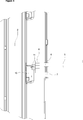
- Figure 1 – is the sideways schematic view of a cooling device.
- Figure 2 — is the perspective view of the cover in an embodiment.
- Figure 3 — is the perspective view of the cover in another embodiment.
- Figure 4 – is the exploded perspective view of the cover and the hinge.
- Figure 5 — is the partial perspective view of the closed position of the cover in an embodiment.
- Figure 6 — is the partial perspective view of the ajar position of the cover in an embodiment.
- Figure 7 — is the partial perspective view of the open position of the cover in an embodiment.
- the cooling device (1) comprises a body (2), a door (3) providing access into the body (2), at least one compartment (4) wherein the items to be cooled are placed, at least one cover (5) that enables the compartment (4) to be covered and that is opened by rotating around a horizontal rotational axis, and a pin (6) disposed on each side of the cover (5), forming the rotational axis.
- the compartments (4) are used for cooling different kinds of items.
- Flap-type covers (5) are used for separating the compartments (4) from one another. The cover (5) opens by rotating 90 degrees around the rotational axis formed by the pin (6).
- the protrusion (7) is situated below the pin (6) in embodiments wherein the cover (5) is opened upwards, and situated above the pin (6) in embodiments wherein the cover (5) is opened downwards.
- the grippers (9) are provided on the hinge (8) so as to hold the protrusion (7) in the open and closed positions of the cover (5). In the open and closed positions of the cover (5) attained by rotating the cover (5) around the axis formed by the pin (6), the hinge (8) holds the protrusion (7) by means of the grippers (9), thus enabling the cover (5) to be balanced.
- the gripper (9) When the cover (5) is closed, the gripper (9) enables the cover (5) to remain in the closed position by supporting the protrusion (7) in the horizontal plane, thus serves as a kind of locking mechanism.
- the cover (5) is prevented from wobbling due to vibrations generated during the operation of the cooling device (1), improving user satisfaction.
- the covers (5) are not required to be detached or adhered by a tape while the cooling device (1) is transported.
- the hinge (8) also houses the pin (6). After being mounted to the cover (5), the hinge (8) is attached to the body (2), thus providing ease of assembly. Consequently, the hinge (8), that enables the cover (5) to be balanced in the open and closed positions, also enables the cover (5) to be secured. By means of this embodiment, no hole or housing is required to be bored on the body (2) to secure the pin (6).
- the hinge (8) comprises at least one claw (11) in order to secure the hinge (8) to the body (2).
- the hinge (8) is firmly secured and the hinge (8) having such claws (11) provides the operator with ease of assembly.
Landscapes
- Engineering & Computer Science (AREA)
- Chemical & Material Sciences (AREA)
- Combustion & Propulsion (AREA)
- Physics & Mathematics (AREA)
- Mechanical Engineering (AREA)
- Thermal Sciences (AREA)
- General Engineering & Computer Science (AREA)
- Refrigerator Housings (AREA)
Abstract
The present invention relates to a cooling device (1) comprising a body (2), a door (3) providing access into the body (2), at least one compartment (4) wherein the items to be cooled are placed, at least one cover (5) that enables the compartment (4) to be covered and that is opened by rotating around a horizontal rotational axis, and a pin (6) disposed on each side of the cover (5), forming the rotational axis.
Description
The present invention relates to a cooling device comprising flap-type covers that provide easy access to the compartments.
In cooling devices, compartments are used for separating different types of items to be cooled inside the body from each other or to form partitions with different temperatures, and flap-type covers that cover the compartments are used to separate the compartments from other parts of the body. In the state of the art, the flap-type covers are enabled to be balanced in the open position by the pins on the hinge seating into a housing when the cover is opened. In balancing the pin by being seated into a housing, the pin can be easily dislodged since the mouth of the housing wherein the pin is seated must be on the line where the pin moves. In order to overcome this problem, the mouth of the housing is designed to be narrower than the pin; however, in this case, the user must apply excessive force in order to fit the pin into the housing and dislodge the pin from the housing. Moreover, in this type of covers, the pins used in securing the cover may break in the case the user accidentally closes the door while the cover is open.
In the Patent Applications No.WO2011080109 and WO2005012812, a cooling device comprising flap-type covers is disclosed.
The aim of the present invention is the realization of a cooling device that can be used easily by the user and that has flap-type covers that can be opened in a robust and secure manner.
The cooling device realized in order to attain the aim of the present invention, explicated in the first claim and the respective claims thereof, comprises a body, a door providing access into the body, at least one compartment inside the body, covers that are used to separate the compartments, and a pin disposed on each side of the cover, enabling the cover to be opened by rotating. The cooling device of the present invention comprises furthermore, a protrusion that is positioned above or below each pin according to the opening direction of the cover, and more than one hinge mounted onto the body and having more than one gripper holding the protrusion.
In the cooling device of the present invention, the cover is enabled to be kept fixed in different positions. While enabling the cover to be kept in the open position, the protrusion allows the cover to be closed by dislodging when the door is closed when the cover is open. Moreover, by means of the gripper that is positioned on the hinge so as to hold the protrusion when the cover is in the closed position, the cover is enabled to be kept as if it is locked in the closed position.
In an embodiment of the present invention, the grippers are positioned on the hinge so that the mouths thereof face opposite directions. By the gripper mouths facing the opposite directions, the cover is enabled to operate in a robust manner during opening/closing.
In an embodiment of the present invention, the hinge is furthermore configured to allow the pin to be seated therein. By means of this embodiment, no additional connection member is required to secure the pin to the body and no housing is required to be bored on the body, and the cover is secured by the hinge that is used for supporting the cover in different positions.
In an embodiment of the present invention, a cavity wherein the hinge is seated is disposed on the body. By means of this embodiment, the user is prevented from seeing the opening/closing mechanism of the cover, increasing his/her perception of quality.
In an embodiment of the present invention, the hinge is attached to the body by means of two claws. During assembly, the workload of the assembly operator is reduced since elements such as screws, that are difficult to attach/detach are not used.
By means of the present invention, the flat-type covers used in the cooling devices are enabled to be balanced in the open and closed positions, and the pins disposed at the edges of the cover are prevented from being broken when the door is closed when the cover is open. Moreover, user satisfaction is improved by enabling the smooth operation of the covers.
The cooling device realized in order to attain the aim of the present invention is illustrated in the attached figures, where:
Figure 1 – is the sideways schematic view of a cooling device.
Figure 2 – is the perspective view of the cover in an embodiment.
Figure 3 – is the perspective view of the cover in another embodiment.
Figure 4 – is the exploded perspective view of the cover and the hinge.
Figure 5 – is the partial perspective view of the closed position of the cover in an embodiment.
Figure 6 – is the partial perspective view of the ajar position of the cover in an embodiment.
Figure 7 – is the partial perspective view of the open position of the cover in an embodiment.
The elements illustrated in the figures are numbered as follows:
1. Cooling device
2. Body
3. Door
4. Compartment
5. Cover
6. Pin
7. Protrusion
8. Hinge
9. Gripper
10. Cavity
11. Claw
The cooling device (1) comprises a body (2), a door (3) providing access into the body (2), at least one compartment (4) wherein the items to be cooled are placed, at least one cover (5) that enables the compartment (4) to be covered and that is opened by rotating around a horizontal rotational axis, and a pin (6) disposed on each side of the cover (5), forming the rotational axis.
In the cooling device (1), the compartments (4) are used for cooling different kinds of items. Flap-type covers (5) are used for separating the compartments (4) from one another. The cover (5) opens by rotating 90 degrees around the rotational axis formed by the pin (6).
The cooling device (1) of the present invention comprises:
- a protrusion (7) that is positioned above or below each pin (6) according to the opening direction of the cover (5), and
- more than one hinge (8) that is disposed on the body (2) and that has more than one gripper (9) enabling the protrusion (7) to be held.
The protrusion (7) is situated below the pin (6) in embodiments wherein the cover (5) is opened upwards, and situated above the pin (6) in embodiments wherein the cover (5) is opened downwards. The grippers (9) are provided on the hinge (8) so as to hold the protrusion (7) in the open and closed positions of the cover (5). In the open and closed positions of the cover (5) attained by rotating the cover (5) around the axis formed by the pin (6), the hinge (8) holds the protrusion (7) by means of the grippers (9), thus enabling the cover (5) to be balanced.
In an embodiment of the present invention, the cooling device (1) comprises two grippers (9) that are positioned on the hinge (8) so that the mouths thereof face opposite directions. The gripper (9) grips the protrusion (7) from below when the cover (5) is fully opened and enables the cover (5) to remain in the open position by its own weight being balanced without requiring user intervention. As the cover (5) is changed from the open position to the closed position, the protrusion (7) is released from the gripper (9), enabling the cover (5) to be closed. Accordingly, the pin (6) is prevented from breaking during the movement of the cover (5). When the cover (5) is closed, the gripper (9) enables the cover (5) to remain in the closed position by supporting the protrusion (7) in the horizontal plane, thus serves as a kind of locking mechanism. Thus, the cover (5) is prevented from wobbling due to vibrations generated during the operation of the cooling device (1), improving user satisfaction. Moreover, the covers (5) are not required to be detached or adhered by a tape while the cooling device (1) is transported.
In an embodiment of the present invention, the hinge (8) also houses the pin (6). After being mounted to the cover (5), the hinge (8) is attached to the body (2), thus providing ease of assembly. Consequently, the hinge (8), that enables the cover (5) to be balanced in the open and closed positions, also enables the cover (5) to be secured. By means of this embodiment, no hole or housing is required to be bored on the body (2) to secure the pin (6).
In an embodiment of the present invention, the cooling device (1) comprises a cavity (10) arranged on the side wall of the body (2), wherein the hinge (8) is disposed. By means of this embodiment, the hinge (8) is prevented from being seen by the user.
In an embodiment of the present invention, the hinge (8) comprises at least one claw (11) in order to secure the hinge (8) to the body (2). By the claws (11) gripping the body (2), the hinge (8) is firmly secured and the hinge (8) having such claws (11) provides the operator with ease of assembly.
In the cooling device (1) of the present invention, the flap-type covers (5) are enabled to be easily opened/closed by the user and the pins (6) are prevented from breaking during opening/closing of the cover (5).
Claims (5)
- A cooling device (1) comprising a body (2), a door (3) providing access into the body (2), at least one compartment (4) wherein the items to be cooled are placed, at least one cover (5) that enables the compartment (4) to be covered and that is opened by rotating around a horizontal rotational axis, and a pin (6) disposed on each side of the cover (5), forming the rotational axis characterized in that- a protrusion (7) that is positioned above or below each pin (6) according to the opening direction of the cover (5), and- more than one hinge (8) that is disposed on the body (2) and that has more than one gripper (9) enabling the protrusion (7) to be held during the open and closed positions of the cover (5).
- A cooling device (1) as in Claim 1, characterized in that two grippers (9) that are disposed on the hinge (8) so that the mouths thereof face opposite directions.
- A cooling device (1) as in Claim 1, characterized in that the hinge (8) that houses the pin (6).
- A cooling device (1) as in any one of the claims, characterized in that a cavity (10) arranged on the side wall of the body (2), wherein the hinge (8) is disposed.
- A cooling device (1) as in any one of the above claims, characterized in that at least one claw (11) that is disposed on the hinge (8) and enables the hinge (8) to be secured to the body (2).
Applications Claiming Priority (2)
| Application Number | Priority Date | Filing Date | Title |
|---|---|---|---|
| TR201315492 | 2013-12-30 | ||
| TRA2013/15492 | 2013-12-30 |
Publications (1)
| Publication Number | Publication Date |
|---|---|
| WO2015101430A1 true WO2015101430A1 (en) | 2015-07-09 |
Family
ID=51894002
Family Applications (1)
| Application Number | Title | Priority Date | Filing Date |
|---|---|---|---|
| PCT/EP2014/073291 Ceased WO2015101430A1 (en) | 2013-12-30 | 2014-10-30 | A cooling device comprising a flap cover |
Country Status (1)
| Country | Link |
|---|---|
| WO (1) | WO2015101430A1 (en) |
Cited By (14)
| Publication number | Priority date | Publication date | Assignee | Title |
|---|---|---|---|---|
| USD839321S1 (en) | 2015-03-17 | 2019-01-29 | Whirlpool Corporation | Refrigerator |
| US10281197B2 (en) | 2016-10-11 | 2019-05-07 | Whirlpool Corporation | Quick shelf adjustment mechanism for a refrigerating appliance |
| US10371436B2 (en) | 2017-11-08 | 2019-08-06 | Whirlpool Corporation | Bin assembly |
| US10473383B2 (en) | 2017-09-08 | 2019-11-12 | Whirlpool Corporation | Refrigerator shelf translation system |
| US10551071B2 (en) | 2018-05-11 | 2020-02-04 | Whirlpool Corporation | Oven rack system with removable support elements |
| USD883348S1 (en) | 2015-10-09 | 2020-05-05 | Whirlpool Corporation | Refrigerator shelf |
| US10655905B2 (en) | 2017-06-13 | 2020-05-19 | Whirlpool Corporation | Flexible compartment for a refrigerator |
| US10677514B2 (en) | 2017-08-01 | 2020-06-09 | Whirlpool Corporation | Door bin with dual material and system lock |
| US10690400B2 (en) | 2017-05-11 | 2020-06-23 | Whirlpool Corporation | Household appliance comprising shelf arrangement |
| US10704825B2 (en) | 2015-03-17 | 2020-07-07 | Whirlpool Corporation | U-shaped tuck shelf |
| US10808944B2 (en) | 2018-01-12 | 2020-10-20 | Whirlpool Corporation | Swinging rack |
| US10823480B2 (en) | 2017-08-01 | 2020-11-03 | Whirlpool Corporation | Air flow mechanism for compartment |
| US10823490B2 (en) | 2017-10-12 | 2020-11-03 | Whirlpool Corporation | Shelf assembly for appliance |
| US11073329B2 (en) | 2018-10-31 | 2021-07-27 | Whirlpool Corporation | Refrigerator shelving frame with snap-in sliding insert |
Citations (7)
| Publication number | Priority date | Publication date | Assignee | Title |
|---|---|---|---|---|
| JPH0632985U (en) * | 1992-09-18 | 1994-04-28 | 株式会社富士通ゼネラル | Door plate opening / closing mechanism |
| EP1338741A2 (en) * | 2002-02-25 | 2003-08-27 | BSH Bosch und Siemens Hausgeräte GmbH | Hinge connection and container with such a hinge |
| WO2005012812A1 (en) | 2003-08-05 | 2005-02-10 | Arcelik Anonim Sirketi | A refrigerator |
| KR20060038844A (en) * | 2004-11-01 | 2006-05-04 | 주식회사 대우일렉트로닉스 | Home Bar Door Operation Structure of Refrigerator |
| WO2009083395A2 (en) * | 2007-12-31 | 2009-07-09 | Arcelik Anonim Sirketi | A cooling device |
| WO2011080109A2 (en) | 2009-12-31 | 2011-07-07 | Arcelik Anonim Sirketi | A refrigerator comprising flap doors |
| CN103256772A (en) * | 2013-06-07 | 2013-08-21 | 合肥华凌股份有限公司 | Refrigerator |
-
2014
- 2014-10-30 WO PCT/EP2014/073291 patent/WO2015101430A1/en not_active Ceased
Patent Citations (7)
| Publication number | Priority date | Publication date | Assignee | Title |
|---|---|---|---|---|
| JPH0632985U (en) * | 1992-09-18 | 1994-04-28 | 株式会社富士通ゼネラル | Door plate opening / closing mechanism |
| EP1338741A2 (en) * | 2002-02-25 | 2003-08-27 | BSH Bosch und Siemens Hausgeräte GmbH | Hinge connection and container with such a hinge |
| WO2005012812A1 (en) | 2003-08-05 | 2005-02-10 | Arcelik Anonim Sirketi | A refrigerator |
| KR20060038844A (en) * | 2004-11-01 | 2006-05-04 | 주식회사 대우일렉트로닉스 | Home Bar Door Operation Structure of Refrigerator |
| WO2009083395A2 (en) * | 2007-12-31 | 2009-07-09 | Arcelik Anonim Sirketi | A cooling device |
| WO2011080109A2 (en) | 2009-12-31 | 2011-07-07 | Arcelik Anonim Sirketi | A refrigerator comprising flap doors |
| CN103256772A (en) * | 2013-06-07 | 2013-08-21 | 合肥华凌股份有限公司 | Refrigerator |
Cited By (24)
| Publication number | Priority date | Publication date | Assignee | Title |
|---|---|---|---|---|
| US11598577B2 (en) | 2015-03-17 | 2023-03-07 | Whirlpool Corporation | U-shaped tuck shelf |
| USD839321S1 (en) | 2015-03-17 | 2019-01-29 | Whirlpool Corporation | Refrigerator |
| US10704825B2 (en) | 2015-03-17 | 2020-07-07 | Whirlpool Corporation | U-shaped tuck shelf |
| USD926235S1 (en) | 2015-10-09 | 2021-07-27 | Whirlpool Corporation | Refrigerator shelf |
| USD1036513S1 (en) | 2015-10-09 | 2024-07-23 | Whirlpool Corporation | Refrigerator shelf |
| USD883348S1 (en) | 2015-10-09 | 2020-05-05 | Whirlpool Corporation | Refrigerator shelf |
| USD978205S1 (en) | 2015-10-09 | 2023-02-14 | Whirlpool Corporation | Refrigerator shelf |
| USD954767S1 (en) | 2015-10-09 | 2022-06-14 | Whirlpool Corporation | Refrigerator shelf |
| US10281197B2 (en) | 2016-10-11 | 2019-05-07 | Whirlpool Corporation | Quick shelf adjustment mechanism for a refrigerating appliance |
| US12066244B2 (en) | 2017-05-11 | 2024-08-20 | Whirlpool Corporation | Household appliance comprising shelf arrangement |
| US10690400B2 (en) | 2017-05-11 | 2020-06-23 | Whirlpool Corporation | Household appliance comprising shelf arrangement |
| US11371771B2 (en) | 2017-05-11 | 2022-06-28 | Whirlpool Corporation | Household appliance comprising shelf arrangement |
| US10655905B2 (en) | 2017-06-13 | 2020-05-19 | Whirlpool Corporation | Flexible compartment for a refrigerator |
| US10823480B2 (en) | 2017-08-01 | 2020-11-03 | Whirlpool Corporation | Air flow mechanism for compartment |
| US10677514B2 (en) | 2017-08-01 | 2020-06-09 | Whirlpool Corporation | Door bin with dual material and system lock |
| US11650000B2 (en) | 2017-08-01 | 2023-05-16 | Whirlpool Corporation | Air flow mechanism for compartment |
| US10473383B2 (en) | 2017-09-08 | 2019-11-12 | Whirlpool Corporation | Refrigerator shelf translation system |
| US10823490B2 (en) | 2017-10-12 | 2020-11-03 | Whirlpool Corporation | Shelf assembly for appliance |
| US11774169B2 (en) | 2017-10-12 | 2023-10-03 | Whirlpool Corporation | Shelf assembly for appliance |
| US10371436B2 (en) | 2017-11-08 | 2019-08-06 | Whirlpool Corporation | Bin assembly |
| US10808944B2 (en) | 2018-01-12 | 2020-10-20 | Whirlpool Corporation | Swinging rack |
| US11796184B2 (en) | 2018-01-12 | 2023-10-24 | Whirlpool Corporation | Oven rack assembly with rotating mounting arms |
| US10551071B2 (en) | 2018-05-11 | 2020-02-04 | Whirlpool Corporation | Oven rack system with removable support elements |
| US11073329B2 (en) | 2018-10-31 | 2021-07-27 | Whirlpool Corporation | Refrigerator shelving frame with snap-in sliding insert |
Similar Documents
| Publication | Publication Date | Title |
|---|---|---|
| WO2015101434A1 (en) | A cooling device comprising a flap cover | |
| US11731144B2 (en) | Centrifuge rotor with locking levers providing visual indication of cover closure | |
| WO2010131813A1 (en) | Refrigerator | |
| WO2017191948A1 (en) | Refrigerator | |
| CA2592830A1 (en) | Universal recessed while-in-use box and cover | |
| WO2017107351A1 (en) | Side-by-side refrigerator | |
| JP4217674B2 (en) | Opening and closing structure of the refrigerator door | |
| JP5344311B2 (en) | Electric thumb turn | |
| CN212477172U (en) | Electrical equipment and door lock thereof | |
| CN105423686A (en) | Side-by-side combination refrigerator | |
| JP6730494B1 (en) | Hinges and cabinets with hinges | |
| JP2008218945A (en) | Hinge structure for electrical and electronic equipment storage box | |
| KR101821209B1 (en) | Laundry Machine | |
| US10309135B2 (en) | Handle and freezer | |
| CN218672765U (en) | Refrigerator | |
| CN218672766U (en) | Refrigerator | |
| JP3140610U (en) | Hinge structure for electrical equipment storage box | |
| JP5344309B2 (en) | Electric thumb turn door mounting structure | |
| JP4737767B2 (en) | Hanging device | |
| JP6650206B2 (en) | Handle structure | |
| CN211088349U (en) | Battery fixing device and unmanned aerial vehicle | |
| CN218672761U (en) | Refrigerator | |
| JP3235163U (en) | Server rack | |
| CN115507586A (en) | Refrigerator | |
| CN113825870A (en) | Washing machine |
Legal Events
| Date | Code | Title | Description |
|---|---|---|---|
| 121 | Ep: the epo has been informed by wipo that ep was designated in this application |
Ref document number: 14796454 Country of ref document: EP Kind code of ref document: A1 |
|
| NENP | Non-entry into the national phase |
Ref country code: DE |
|
| 122 | Ep: pct application non-entry in european phase |
Ref document number: 14796454 Country of ref document: EP Kind code of ref document: A1 |