WO2015093142A1 - 混合物生成装置及び混合物生成方法 - Google Patents
混合物生成装置及び混合物生成方法 Download PDFInfo
- Publication number
- WO2015093142A1 WO2015093142A1 PCT/JP2014/077972 JP2014077972W WO2015093142A1 WO 2015093142 A1 WO2015093142 A1 WO 2015093142A1 JP 2014077972 W JP2014077972 W JP 2014077972W WO 2015093142 A1 WO2015093142 A1 WO 2015093142A1
- Authority
- WO
- WIPO (PCT)
- Prior art keywords
- liquid
- milk
- heat exchanger
- mixture
- temperature
- Prior art date
- Legal status (The legal status is an assumption and is not a legal conclusion. Google has not performed a legal analysis and makes no representation as to the accuracy of the status listed.)
- Ceased
Links
Images



Classifications
-
- A—HUMAN NECESSITIES
- A47—FURNITURE; DOMESTIC ARTICLES OR APPLIANCES; COFFEE MILLS; SPICE MILLS; SUCTION CLEANERS IN GENERAL
- A47J—KITCHEN EQUIPMENT; COFFEE MILLS; SPICE MILLS; APPARATUS FOR MAKING BEVERAGES
- A47J31/00—Apparatus for making beverages
- A47J31/40—Beverage-making apparatus with dispensing means for adding a measured quantity of ingredients, e.g. coffee, water, sugar, cocoa, milk, tea
- A47J31/401—Beverage-making apparatus with dispensing means for adding a measured quantity of ingredients, e.g. coffee, water, sugar, cocoa, milk, tea whereby the powder ingredients and the water are delivered to a mixing bowl
Definitions
- the present invention relates to a mixture generating apparatus and a mixture generating method for automatically mixing a mixture raw material and a high-temperature liquid to generate a liquid mixture. More specifically, a milk powder preparation apparatus for infants having a function of generating milk as a liquid mixture by supplying high temperature liquid to dry powdered milk (powdered milk) as a raw material for the mixture and cooling the milk to an appropriate temperature And its usage.
- the milk to be given to infants is considered to be about 40 ° C. in consideration of the temperature and body temperature of breast milk. For this reason, in order to prepare dry powdered milk and prepare a mixture to be given to infants, it is necessary to cool the mixture to about 40 ° C. after preparing using a liquid boiled to 70 ° C. or higher.
- milk preparation apparatuses disclosed in Patent Document 1 and Patent Document 2 are known.
- sterilization is performed by heating the milk preparation water with a heater installed in a tank for storing the milk preparation water. Moreover, the supply flow rate of high temperature milking water is adjusted with a Coriolis mass flow meter. Thereby, automatic milk adjustment can be performed in-line.
- a concentrate is prepared by mixing an amount of formula necessary for the total amount of the mixture with a certain amount of hot water. And it is configured to adjust the milk at the proper temperature by adding some low temperature liquid to the concentrate to reach the final volume of the mixture.
- Japanese Patent Publication Japanese Unexamined Patent Application Publication No. 2007-252427 (published on October 4, 2007)”
- the milk preparation apparatus disclosed in Patent Document 2 can automatically perform a series of operations from the production of milk to cooling, but it is necessary to dilute the concentrate. For this reason, the stirring and mixing process for mixing warm water and cooling water is required. However, in that case, there is a possibility that bubbles such as a large amount of air are contained in the milk. If air bubbles or the like are contained in milk, air easily enters the baby's stomach, and large burps or the like are easily produced, which causes respiration due to the beat.
- the burp is insufficiently discharged, it may cause night crying. Furthermore, in order to prevent the dry powder milk from remaining undissolved, it is necessary to prepare a concentrate using a large amount of high-temperature water. Therefore, in order to adjust the milk after the preparation to a constant temperature and a constant amount, it is necessary to use cooling water at room temperature or lower, and it is necessary to provide a cooling device in the milk preparation device. In order to lower the temperature of the cooling water and keep it constant by the cooling device, it takes a long time before it becomes possible to start milk preparation from power ON. In addition, there is a problem from the viewpoint of cost, such as the need to provide a cooling device. Furthermore, the milk preparation method is different from the safe milk preparation method according to “Guidelines for Safe Formulation, Storage and Handling of Infant Dry Powdered Milk”.
- the present invention has been made in view of the above-described conventional problems, and an object thereof is to produce a liquid mixture by mixing a heated liquid and a raw material for a mixture, and to cool the liquid mixture to an appropriate temperature. It is an object of the present invention to provide a mixture generating apparatus and a mixture generating method capable of automatically performing the step of performing the steps.
- the mixture generation device includes a liquid heating unit that heats the supplied liquid and first heat that exchanges heat between the liquid heated by the liquid heating unit. Heat exchange is performed between the exchanger, the mixture raw material and the liquid heat-exchanged in the first heat exchanger to generate a liquid mixture, and the liquid mixture generated in the mixing unit.
- a second heat exchanger is provided.
- a mixture generation method includes a liquid heating step of heating a supplied liquid, and a first heat exchange of the heated liquid with a first heat exchanger.
- a heat exchange step a mixing step of mixing the raw material for the mixture and the heat-exchanged liquid to produce a liquid mixture, and a second heat for exchanging heat of the produced liquid mixture in a second heat exchanger And an exchange process.
- a mixture generating device and a mixture capable of automatically performing a process of mixing a heated liquid and a raw material for the mixture to form a liquid mixture and cooling the liquid mixture to an appropriate temperature.
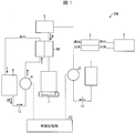
- FIG. 1 It is a block diagram which shows the structure of the powdered milk preparation apparatus as a mixture production
- FIG. 1 is a block diagram showing a configuration of a powdered milk preparation device 10A of the present embodiment.
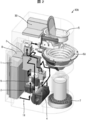
- FIG. 2 is a perspective view showing the configuration of the powdered milk preparation device 10A of the present embodiment.
- a powdered milk preparation device 10 ⁇ / b> A as a mixture generation device of the present embodiment is configured to supply a liquid tank 1 that stores liquid and a liquid L stored in the liquid tank 1.
- Heater 4 as a liquid heating unit for boiling and sterilizing liquid L preliminarily heated in 3, powder dried milk as a raw material for a mixture of liquid sterilized by boiling and cooled in first heat exchanger 3
- the milk preparation part 5 as a mixing part for adjusting and mixing milk powder to an appropriate amount and generating milk M as a liquid mixture, and the milk M generated in the milk preparation part 5 to an arbitrarily set temperature Second heat to regulate A heat exchanger 60, a milk receiving part 7 for storing milk M flowing out from the second heat exchanger 60, and a cooling water for cooling the milk M passing through the second heat exchanger 60.
- the cooling water tank 8, the cooling water pipe 12 and cooling water pump 9 for supplying cooling water into the second heat exchanger 60, and the liquid pump 2 and cooling so that the temperature of the milk M becomes a set value.
- a control storage unit 20 for adjusting the output of the water pump 9.
- the liquid tank 1 can be filled with a liquid L for milk adjustment such as tap water or carbonated water. Inside the liquid tank 1, a water level sensor (not shown) for sensing the water level of the liquid L poured into the liquid tank 1 and a temperature sensor for sensing the water temperature are provided. For this reason, the water level, temperature, etc. of the liquid L poured into the liquid tank 1 can be sensed.
- a liquid L for milk adjustment such as tap water or carbonated water.
- the water level sensor various types of sensors having different measurement principles and usage methods can be used. That is, the water level sensor includes, for example, an electrode type, a magnetic type, and a hydraulic type, but any type of sensor may be used as long as the water level in the liquid tank 1 can be detected. However, from the viewpoint of hygiene, it is preferable to select a liquid L type that can be detected without contact. In this embodiment, for example, a magnetic water level sensor that can be measured in a non-contact manner is used.
- the temperature sensor can sense the water temperature in the liquid tank 1
- any type having a different principle and usage may be used. However, what can be detected without contact with the liquid L is preferable.
- the liquid tank 1 is provided with, for example, a filter made of activated carbon or an ion exchange membrane (not shown) to remove impurities, chlorine, bacteria, bacteria, ionic metals, and other components in the poured liquid L. It is good also as a structure. Furthermore, it is preferable that the liquid L is supplied to the heater 4 and heated immediately after the liquid L is poured into the liquid tank 1. Moreover, in order to store the liquid L for a long time, it is good also as a structure which installs sterilization means, such as an ultraviolet irradiation device, for example in the upper part of the liquid tank 1, and irradiates the stored liquid L with an ultraviolet-ray and can sterilize. Further, for example, the liquid L may be supplied by directly connecting the liquid tank 1 and an external water tap or the like.
- sterilization means such as an ultraviolet irradiation device
- the liquid supply pipe 11 and the cooling water pipe 12 are flow paths through which the liquid L stored in the liquid tank 1 and the cooling water tank 8 passes.
- the material for the liquid supply pipe 11 and the cooling water pipe 12 for example, pipes such as metal pipes such as SUS and silicon or Teflon (registered trademark) resin pipes can be used.
- a silicon tube having an inner diameter of ⁇ 3 mm is used as the liquid supply conduit 11, and for example, connection with each part such as the liquid tank 1 and the liquid pump 2 is performed using a fixing tool such as a hose clip. Yes.
- the size of the material and inner diameter of the tube can be arbitrarily set.
- the connection with each part can select the arbitrary fixing methods suitable for the size etc. of the tube.
- a solenoid type or a diaphragm type pump can be used as the liquid pump 2 and the cooling water pump 9.
- a solenoid pump having a maximum pressure of 0.8 MPa and a maximum flow rate of 800 cc / min is used as the liquid pump 2 and the cooling water pump 9.
- the adaptive pressure and applicable flow rate of the pump are preferably selected according to the configuration and specifications of the powdered milk preparation device 10A.
- the first heat exchanger 3 increases the temperature of the liquid L for milk production, reduces the load required by the heater 4, and decreases the temperature of the boiled hot liquid L that has flowed out of the heater 4. it can.
- the liquid L close to 100 ° C. is the minimum preparation temperature in accordance with “Guidelines for safe preparation, storage and handling of dry powdered milk for infants” 70 The temperature is lowered to ° C. Thereby, it is set as the structure which reduces destruction of vitamins as much as possible.
- the first heat exchanger 3 for example, an aluminum counter-current or co-current liquid-liquid heat exchanger can be used.
- an aluminum counter-current liquid-liquid heat exchanger having a relatively high heat exchange efficiency is used.
- the material, internal shape, configuration, and the like of the first heat exchanger 3 may be arbitrarily selected.
- Heater 4 heats and sterilizes liquid L for milk production.
- the heater 4 may be any shape or structure.
- a coil-type heater, a sheet heater, a silicon heater, or the like may be used as long as the liquid L supplied to the heater unit can be heated for a predetermined time to be boiled and sterilized.
- the heater 4 of the present embodiment is provided with a temperature sensor (not shown) so that the heating temperature of the heater 4 can always be measured.
- the milk preparation unit 5 adjusts the milk M by mixing dry powdered milk that is set in advance, that is, powdered milk, and the liquid L that has been boiled for milk production.
- a dry powder milk installation unit for holding the dry powder milk is provided below the housing.
- generate milk M is installed in the dry powdered milk installation part.
- a nozzle for supplying a liquid L for generating milk M is provided on the side of the milk preparation unit 5. For this reason, the liquid L supplied from the nozzle can discharge
- the piping connection between the milk preparation unit 5 and the first heat exchanger 3 has a structure that can be easily removed, such as a one-touch connector. For this reason, the inside of the powdered milk preparation device 10A can be easily cleaned and sterilized, for example, by immersion in a sodium hypochlorite solution.
- a contact switch (not shown) is provided on the outer wall surface of the milk conditioning unit 5. For this reason, when the removed milk adjustment part 5 is not set correctly, the circuit of the attachment part is disconnected.
- the milk receiving part 7 is a place where a container for storing the produced milk M such as a baby bottle is installed.
- the milk receiving portion 7 has a structure in which a mesh-structured lid is attached above a saucer-like container, and for example, spilled milk M can be drained.
- the cooling water tank 8 is used to store the cooling water CW for heat exchange for adjusting the temperature of the milk M adjusted in the milk preparation unit 5 to an arbitrary temperature in the second heat exchanger 60. .
- the cooling water CW stored in the inside for example, tap water or commercially available coolant liquid can be used, and it is preferable to use a liquid having a large specific heat as much as possible.
- the physical properties such as the viscosity are very high, it is difficult to circulate the cooling water CW. Therefore, it is more preferable to select according to the operation specifications of the cooling water pump 9.
- a water level sensor (not shown) for sensing the liquid water level and a temperature sensor for sensing the water temperature are provided. For this reason, the water level, temperature, etc. of the liquid poured into the cooling water tank 8 can be sensed.
- a cooling unit such as a Peltier may be installed in the cooling water tank 8 to adjust the temperature of the cooling water CW.
- the second heat exchanger 60 adjusts the temperature of the milk M set arbitrarily by performing heat exchange between the dry powdered milk adjusted by the milk preparation unit 5 and the cooling water CW.
- a liquid-liquid heat exchanger similar to the first heat exchanger 3 can be used as the second heat exchanger 60.
- the mixture adjusted by the milk preparation unit 5 is allowed to flow as a high-temperature fluid into one of the flow paths of the second heat exchanger 60.
- the second heat exchanger 60 is connected to the cooling water tank 8 and the cooling water pump 9 through the cooling water pipe 12. For this reason, the cooling water CW stored in the cooling water tank 8 is sent to the second heat exchanger 60 by the cooling water pump 9 and passes through the flow path inside the second heat exchanger 60. Heat exchange takes place. Therefore, the second heat exchanger 60 of the present embodiment has a circulation cycle structure in which the cooling water CW after heat exchange is returned to the cooling water tank 8.
- a liquid-liquid heat exchanger similar to the first heat exchanger 3 is used for the second heat exchanger 60.
- the connection between the second heat exchanger 60 and the milk conditioning unit 5 and the cooling water pipe 12 has a structure that can be easily detached, such as a one-touch connector, like the milk conditioning unit 5. For this reason, the inside of the powdered milk preparation device 10A can be easily cleaned and sterilized, for example, by immersion in a sodium hypochlorite solution.
- the second heat exchanger 60 is also provided with a contact switch (not shown) on the outer wall surface as in the case of the milk conditioning unit 5, and the removed second heat exchanger 60 is not set correctly. Will break the circuit.
- the second heat exchanger 60 performs milk heat exchange, cleaning, disinfection, and state confirmation are easy.
- the second heat exchanger 60 of the present embodiment has the following configuration.
- the configuration of the second heat exchanger 60 of the present embodiment will be described in detail based on FIG. 2, FIG. 3, and FIG.
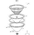
- FIG. 3 is an exploded perspective view showing the configuration of the second heat exchanger 60 of the present embodiment.
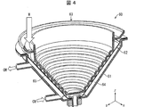
- FIG. 4 is a perspective view showing a part of the configuration of the second heat exchanger 60 of the present embodiment in a cutaway manner.
- the second heat exchanger 60 of the present embodiment includes a flow path forming first member 61 and a flow path as a first flow path forming member having a container shape.
- the diameter of the inner peripheral surface of the container-shaped peripheral wall portion gradually decreases from the upper part toward the lower part. Further, the first flow path 64 through which the cooling water CW flows is formed between the flow path forming first member 61 and the flow path forming second member 62 in the peripheral wall portion.
- the cooling water CW and A spiral second flow path 65 is formed through which the milk M to be heat-exchanged flows.
- the flow path forming third member 63 is a corrugated member.
- the flow path forming first member 61 and the flow path forming second member 62 constituting the first flow path forming member are such that the diameter of the inner peripheral surface of the container-shaped peripheral wall portion is from the top to the bottom. It is getting smaller gradually. For this reason, by arranging the second flow path-shaped member inside the first flow path forming member, a spiral is formed between the inner peripheral surface of the first flow path forming member and the second flow path forming member.
- the second flow path 65 can be easily formed. Further, the diameter of the second flow path 65 formed in this way gradually decreases from the upper part (upstream side) to the lower part (downstream side).
- the second flow path 65 is formed in a spiral shape and has a long flow path length, the heat exchange efficiency between the milk M flowing through the second flow path 65 and the cooling water CW flowing through the first flow path 64 is high. It becomes good. Furthermore, since the flow path forming third member 63 is a corrugated member, the surface area for air cooling is increased, and the cooling efficiency of the milk M is increased.
- the second flow path shape member is detachably disposed with respect to the first flow path forming member, the second flow path shape member can be removed to clean the second flow path 65, Disinfection and status confirmation can be easily performed.
- the second heat exchanger 60 of the present embodiment has good heat exchange efficiency, is easy to clean, disinfect, and check the state of the fluid flow path, and is suitable for cooling the milk M. I can say that.
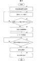
- FIG. 5 is a flowchart showing an operation flow and usage method of the powdered milk preparation device 10A of the present embodiment.
- a user of the powdered milk preparation device 10A supplies the liquid L for adjusting the milk M and the cooling water CW into the liquid tank 1 and the cooling water tank 8 shown in FIG. Thereafter, after the amount of dry powdered milk necessary for adjustment is put into the milk preparation unit 5 in advance, the milk preparation unit 5 and the second heat exchanger 60 are attached to the powder milk milk preparation device 10A.
- the power of the powdered milk preparation device 10A is turned on (S1).
- the liquid supply to each liquid tank 1 and the cooling water tank 8, the milk conditioning unit 5 and the second heat exchanger 60 are attached in any order, and the user may perform any operation.
- the confirmation of attachment of the milk conditioning unit 5 and the second heat exchanger 60 is performed by the contact switch described above, and the circuit is disconnected when the attachment of each part is insufficient. Therefore, it is possible to check the attachment state based on whether or not the circuit is disconnected. If the installation is insufficient, for example, a warning sound such as a buzzer or a warning means such as a blinking lamp is transmitted to the user to request confirmation of the installation or re-installation.
- the initial sensing operation by the water level sensor and the temperature sensor is performed by measuring the water level and the water temperature in each liquid tank 1 and the cooling water tank 8.
- a reference value is set in advance for the measured values of each water level sensor and temperature sensor, and it is determined whether or not the reference value is exceeded.
- predetermined power is supplied to the heater 4, and the preheating operation, which is step (S5), is performed one after another.
- the measured value falls below the reference value, it is transmitted to the user using warning means such as a warning sound such as a buzzer or blinking of a lamp or the like, as in the case of the above-described attachment confirmation. Then, for example, the user is prompted to supply liquid into the tank so that the measured value exceeds the reference value.
- the maximum value of milk M that can be generated per operation operation when the powdered milk preparation device 10A is operated is used as the reference value.
- the maximum value or less is set as the reference value, there is a possibility that the adjustment amount of the milk M is lower than the amount requested by the user. Therefore, it is preferable to set the maximum value that can be adjusted in one operation.
- FIG. 6 is a graph plotting the relationship between the liquid temperature flowing from the first heat exchanger 3 into the milk preparation unit 5 and the liquid temperature in the liquid tank 1.
- the reference value of the temperature sensor is determined according to the heat exchange capability of the first heat exchanger 3. First, as shown in FIG. 6, the relationship data between the liquid temperature flowing from the first heat exchanger 3 into the milk preparation unit 5 and the liquid temperature in the liquid tank 1 is acquired.
- the liquid temperature supplied to the milk preparation unit 5 is defined as 70 ° C. or higher. For this reason, the liquid temperature in the tank of the liquid tank 1 in which the temperature in the milk adjustment part 5 becomes 70 degreeC or more is set as a reference value.
- the liquid temperature in the tank of the liquid tank 1 should be 15 ° C. or higher in order for the temperature in the milk preparation unit 5 to be 70 ° C. or higher. Therefore, in this embodiment, the reference value of the temperature sensor is set to 15 ° C., for example.
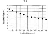
- FIG. 7 is a graph showing the relationship between the temperature of the milk M that has passed through the second heat exchanger 60 and the cooling water supply flow rate in the powdered milk preparation device 10A.
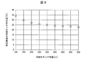
- FIG. 8 is a graph showing the relationship between the cooling water tank water temperature and the cooling water tank capacity after heat exchange of the second heat exchanger 60 in the powdered milk preparation device 10A.
- FIG. 9 is a graph showing the relationship between the temperature of the liquid mixture that has passed through the second heat exchanger 60 and the cooling water temperature in the powdered milk preparation device 10A.
- the amount and temperature of the cooling water CW are determined by the heat exchanger characteristics of the second heat exchanger 60. It is desirable to do. Therefore, first, the cooling water CW having a constant temperature is supplied into the cooling water tank 8 and the heat exchange characteristics of the second heat exchanger 60 are measured to determine the supply flow rate of the cooling water CW.
- the temperature increase in the cooling water tank capacity and the cooling water tank 8 after heat exchange is measured at the supply flow rate determined as described above.
- the minimum capacity of the cooling water tank 8, that is, the water level sensor position is determined.
- the heat exchanger performance is measured when the cooling water temperature is changed. Based on this result, the reference temperature of the cooling water CW, that is, the reference value of the temperature sensor is determined. still.
- the temperature of the high-temperature fluid supplied to the second heat exchanger 60 is set to the same temperature as the temperature flowing out of the milk conditioning unit 5.
- the relationship between the cooling water supply flow rate shown in FIG. 7 and the high temperature fluid outlet temperature from the second heat exchanger 60, and the cooling water supply flow rate shown in FIG. 8 and the cooling water temperature after completion of heat exchange. Determined by the relationship. Specifically, since the heat exchanger outlet temperature is 40 ° C. close to the body temperature and the cooling water temperature rise after heat exchange is small, the supply flow rate is 300 cc / min and the water level sensor reference value is 400 cc. In this case, the cooling water temperature at the time of measurement is 15 ° C.
- the cooling water temperature at which the high temperature fluid outlet temperature is close to 40 ° C. 10 ° C. is set as the reference value of the temperature sensor.
- the cooling water CW after heat exchange with the milk M exiting the milk preparation unit 5 rises to about 25 to 35 ° C. as shown in FIG.
- the cooling water temperature further increases. Therefore, in the present embodiment, even if the milk M is continuously generated, the cooling water CW and the cooling water CW are connected via the second heat exchanger 60 in order to prevent the cooling water temperature from rising above a predetermined temperature. Heat exchange with air is performed for an arbitrary time.
- the second heat exchanger 60 is filled with air at an environmental temperature. For this reason, the cooling water temperature can be lowered by operating the cooling water pump 9 to have a preset flow rate. In that case, the supply flow rate from the cooling water pump 9 can be set arbitrarily. However, in order to increase the heat transfer coefficient during heat exchange and increase the heat exchange efficiency, it is preferable to set the supply flow rate from the cooling water pump 9 as high as possible.
- the heat exchange time depends on the set value of the upper limit temperature of the cooling water CW. For this reason, it is preferable to measure each cooling water inlet temperature and outlet temperature beforehand using the 2nd heat exchanger 60, and to determine heat exchange time from the time until it reaches upper limit temperature.
- the temperature of the liquid L flowing into the heater 4 is controlled to be a preset temperature set value.
- the temperature set value is set to 50 ° C., for example.
- control method for example, a control method such as ON-OFF control or PID (Proportional Integral Derivative) control can be used, and other control methods may be used.
- the temperature set value can be arbitrarily set in consideration of the heater performance such as the heating time from the preheating temperature to the temperature at the time of milk M production, the milk M production tact, and the like.
- the preheating operation is performed in order to shorten the time from when the user inputs the milk M production conditions until the milk M is actually produced. This is done to save energy when implemented in Therefore, when the above points are not considered, it is not always necessary to perform the preheating operation.
- the user of the powdered milk preparation device 10A can input the beverage generation condition, that is, the milk M generation condition, and therefore the beverage generation condition is input. It is determined whether or not (S6).
- the production conditions for the milk M include, for example, the adjustment amount and adjustment temperature of the milk M.
- the adjustment amount can be set from 80 cc to 20 cc, for example.
- the maximum adjustment amount can be adjusted up to 240 cc, and the adjustment temperature can be set at 40 ⁇ 5 ° C.
- the cooling water pump 9 starts driving under the above-described cooling water conditions, and the cooling water CW is supplied into the cooling water pipe 12 and the flow path of the second heat exchanger 60.
- the flow rate of the supplied cooling water CW varies depending on the adjustment temperature input according to the above-described milk M production conditions. That is, the temperature of the milk M is adjusted by changing the supply flow rate of the cooling water CW.
- the supply flow rate X of the cooling water CW according to the input is set by calculating the supply flow rate X from the value of the adjustment temperature Y of the milk M arbitrarily input by the user.
- the linear approximation line changes slightly for each temperature of the cooling water CW. Therefore, it is preferable to measure the relationship between the cooling water supply flow rate and the high-temperature fluid outlet temperature from the second heat exchanger 60 in advance for each temperature of the cooling water CW and calculate a linear approximation line. Thereby, it becomes possible to control the adjustment temperature of the milk M more accurately by changing the approximate line to be referred to according to the temperature of the cooling water CW.
- the input power amount and the heater temperature are set so that the supplied liquid L becomes a temperature at which the liquid L can be boiled inside the heater 4 within the liquid residence time in the heater 4.
- the liquid residence time of the liquid L in the heater 4 is determined by the flow rate of the liquid L supplied by the liquid pump 2 and the inner diameter of the liquid supply pipe 11.
- the input power is 1100 W and the heater temperature is 110 ° C.
- the liquid pump 2 When the heater 4 reaches a sufficient temperature, the liquid pump 2 is driven and supply of the liquid L in the liquid tank 1 is started.
- the supply flow rate by the liquid pump 2 can be arbitrarily set, and can be determined in consideration of the high temperature side outlet fluid temperature of the first heat exchanger 3 and the production tact of the milk M.
- the production tact of milk M is set to 240 cc / min, for example, as the supply flow rate at which the outlet fluid temperature of the first heat exchanger 3 is 70 ° C. or higher.
- the adjustment amount of the milk M is performed by adjusting the driving time of the liquid pump 2 such that, for example, when the adjusting amount is 120 cc, the driving time of the liquid pump 2 is 30 seconds.
- the liquid L supplied from the liquid pump 2 is subjected to heat exchange by the first heat exchanger 3 and is supplied to the heater 4 after the temperature rises to some extent.
- the liquid L supplied into the heater 4 passes through the first heat exchanger 3 as a high-temperature fluid again after being boiled and sterilized.
- the liquid L that has passed through the first heat exchanger 3 is cooled from the boiling temperature to about 70 ° C. and supplied to the milk preparation unit 5.
- the liquid L is mixed with dry powdered milk, that is, powdered milk, and is produced as milk M at about 70 ° C.
- the produced milk M is cooled to an arbitrary temperature in the second heat exchanger 60.
- the cooled milk M is supplied into a container such as a baby bottle installed in the milk receiving part 7.
- milk M is produced in compliance with “Guidelines for Safe Formulation, Storage and Handling of Dry Powdered Milk for Infants”, And cooling from milk preparation to arbitrary temperature can be performed automatically.
- the liquid tank 1 and the liquid pump 2 which are supply means for supplying water as the liquid L for milk preparation, and the temperature of the supplied water are set.
- a temperature sensor of the liquid tank 1 that is a measuring means for measuring
- a control storage unit 20 that is a setting means for setting a supply amount of milking water, and a heating means for heating the water for milking
- a mixing unit for mixing a certain heater 4 a first heat exchanger 3, which is a first adjusting means for adjusting heated water to a milk preparation temperature, and dry powdered milk and heated water
- a milk conditioning unit 5 and a second heat exchanger 60 that is a first adjusting means for adjusting the milk M as a liquid mixture flowing out of the milk conditioning unit 5 to an appropriate temperature are provided.
- the water for milk preparation supplied at normal temperature by the heater 4 is boiled and sterilized. Thereafter, the hot water boiled by the heater 4 is adjusted to a temperature of about 70 ° C. by the first heat exchanger 3 and mixed with the dry powdered milk by the milk preparation unit 5.
- the 2nd heat exchanger 60 which adjusts the temperature of the milk M, it cools directly before the milk M flows in into containers, such as a baby bottle. For this reason, the milk M can be efficiently cooled in a short time.
- the temperature of the milk M is adjusted by referring to the flow rate table of the cooling water CW according to the water temperature of the cooling water CW based on the graphs of FIGS. 7 to 9, and flexibly changing the flow rate of the cooling water CW. To do. For this reason, since it is not necessary to cool the milk M with a separate cooling device, the cost of the powdered milk preparation device 10A can be reduced.
- the adjusted milk M is cooled in-line using the second heat exchanger 60, the mixing of bubbles can be minimized.
- the procedure of the mixture generation method of the present embodiment complies with the “Guidelines on Safe Formulation, Storage and Handling of Infant Dry Powdered Milk”. Furthermore, since all the mixture generation processes are performed in-line, it is possible to adjust milk M having an arbitrary temperature and amount in a short time after supplying water at room temperature.
- the heater 4 that heats the supplied liquid L and the first heat exchanger 3 that exchanges heat between the liquid L heated by the heater 4.
- a second heat exchanger 60 for exchanging heat.
- generation method in this Embodiment is the liquid heating process which heats the supplied liquid L, and the 1st heat exchange process which heat-exchanges the heated liquid L in the 1st heat exchanger 3.
- the heater 4 heats the supplied liquid L in the liquid heating step.
- the first heat exchanger 3 performs heat exchange on the liquid L heated by the heater 4 in the first heat exchange step.
- the milk preparation unit 5 generates milk M by mixing dry powdered milk, that is, powdered milk, and the liquid L heat-exchanged in the first heat exchanger 3 in the mixing step.
- the second heat exchanger 60 performs heat exchange on the milk M generated in the milk preparation unit 5 in the second heat exchange step.
- the powdered milk preparation device 10A and the mixture capable of automatically performing the process of mixing the heated liquid L and dry powdered milk, that is, powdered milk to produce milk M and cooling the milk M to an appropriate temperature.
- a generation method can be provided.
- the first heat exchanger 3 exchanges heat between the liquid L supplied to the heater 4 and the liquid L heated by the heater 4. As a result, the temperature of the liquid L supplied to the heater 4 is raised, and the liquid L heated by the heater 4 is cooled and kept in a temperature range of 70 ° C. or higher.
- the liquid L flowing into the heater 4 is preheated by the first heat exchanger 3, the required power amount in the heater 4 can be reduced. Further, the liquid L heated by the heater 4 is heat-exchanged by the first heat exchanger 3 using the liquid L flowing into the heater 4. For this reason, the temperature of the liquid L flowing into the milk preparation unit 5 can be efficiently cooled. Furthermore, the 1st heat exchanger 3 cools the liquid L heated with the heater 4, and keeps it in the temperature range of 70 degreeC or more. As a result, the powder milk preparation device 10A that complies with the “Guidelines for Safe Formulation, Storage and Handling of Dry Powdered Milk for Infants” jointly created by WHO (World Health Organization) and FAO (United Nations Food and Agriculture Organization) Can be provided.
- WHO World Health Organization
- FAO United Nations Food and Agriculture Organization
- the second heat exchanger 60 includes a flow path forming first member 61 and a flow path forming second as a first flow path forming member having a container shape.
- a member 62, and a flow path forming third member 63 as a second flow path shape member disposed detachably with respect to the first flow path forming member are provided inside the first flow path forming member. ing.
- the flow path forming first member 61 and the flow path forming second member 62 as the first flow path forming members are such that the diameter of the inner peripheral surface of the container-shaped peripheral wall portion gradually decreases from the top to the bottom, and cooling A first flow path 64 for flowing water CW is formed between the flow path forming first member 61 and the flow path forming second member 62 in the peripheral wall portion. Further, between the flow path forming second member 62 that forms the inner peripheral surface of the first flow path forming member and the flow path forming third member 63 as the second flow path forming member, the cooling water CW and A spiral second flow path 65 is formed through which the milk M to be heat-exchanged flows.
- the second heat exchanger 60 of the present embodiment has good heat exchange efficiency, and is easy to clean, sterilize and check the state of the fluid flow path, and is suitable for cooling the milk M.
- the powdered milk preparation device 10B of the present embodiment includes a heater 4 and a first heat exchanger 3 as shown in FIG. The difference is that the first bypass line 31 via the first electromagnetic valve 30 is formed in the liquid supply pipe 11 therebetween.
- FIG. 10 is a block diagram showing the configuration of the powdered milk preparation device 10B of the present embodiment.
- the powdered milk preparation device 10 ⁇ / b> B of the present embodiment includes a liquid supply pipe 11 as a flow path between the heater 4 as a liquid heating unit and the first heat exchanger 3.
- a first bypass line 31 is provided as a first branch flow path that is connected to a milk conditioning unit 5 as a mixing unit via a first electromagnetic valve 30 as a first valve capable of adjusting the degree of opening and closing. Yes.
- the description is abbreviate
- the powdered milk preparation device 10B of the present embodiment employs the first electromagnetic valve 30 that can distribute and supply the liquid L in two directions.
- the first solenoid valve 30 can arbitrarily adjust the degree of opening and closing by adjusting the supply voltage or current.
- the first heat exchanger 3 when the temperature of the liquid L supplied to the heater 4 through the first heat exchanger 3 is lower than 15 ° C., the first heat exchanger 3 is used. Thus, the temperature of the high-temperature liquid L flowing into the milk conditioning unit 5 becomes 70 ° C. or less. In this case, it can be said that the amount of heat exchange in the first heat exchanger 3 is excessive.
- the opening / closing degree of the first electromagnetic valve 30 is adjusted according to the temperature of the supplied liquid L. Specifically, when the liquid L having a temperature lower than 15 ° C. is supplied to the heater 4, the first electromagnetic valve 30 is opened and a part of the high temperature liquid L that has passed through the heater 4 is passed through the first bypass line 31. And mixed with the liquid L of 70 ° C. or less that has passed through the first heat exchanger 3. Thereby, the temperature of the liquid L can be adjusted to 70 ° C. immediately before the milk preparation unit 5.
- the temperature of the liquid L immediately before the milk preparation unit 5 is measured in advance, and the measurement data Determine based on.
- the liquid supply conduit 11 between the heater 4 and the first heat exchanger 3 has the first electromagnetic valve whose degree of opening and closing can be adjusted.
- a first bypass line 31 connected to the milk conditioning unit 5 via 30 is provided.
- the liquid supply conduit 11 between the heater 4 and the first heat exchanger 3 is connected to the milk conditioning unit 5 and the first through a first electromagnetic valve 30 whose degree of opening and closing can be adjusted. It is preferable that a first bypass line 31 connected to the liquid supply pipe 11 which is a flow path between the heat exchanger 3 and the heat exchanger 3 is provided.
- the temperature of the heated liquid L which flows into the milk preparation part 5 may be 70 degrees C or less.
- the liquid supply conduit 11 between the heater 4 and the first heat exchanger 3 is connected to the milk adjustment unit 5 via the first electromagnetic valve 30 that can adjust the degree of opening and closing.
- a first bypass line 31 is provided.
- the temperature of the heated liquid L can be suppressed to 70 ° C. or less.
- milk M is produced in compliance with the “Guidelines for Safe Formulation, Storage and Handling of Dry Powdered Milk for Infants”. It becomes possible.
- the powdered milk preparation device 10C as the mixture generation device of the present embodiment has a configuration just before the milk preparation unit 5 in addition to the configuration of the powdered milk preparation device 10A of the first embodiment.
- the point which comprises the 2nd bypass line 41 via the 2nd solenoid valve 40 differs.
- FIG. 11 is a block diagram showing a configuration of a powdered milk preparation device 10C in the present embodiment.
- the powdered milk preparation device 10 ⁇ / b> C of the present embodiment includes a second bypass line 41 via the second electromagnetic valve 40 immediately before the milk preparation unit 5, and this second bypass Line 41 is connected to the drain of milk receiver 7.
- the second bypass line 41 is used as a cleaning maintenance line in the liquid supply pipeline 11.
- the cleaning maintenance in the liquid supply conduit 11 can also be performed by supplying the liquid L in the direction of the milk preparation unit 5 without setting dry powdered milk, that is, powdered milk, in the milk preparation unit 5. However, in that case, the cleaning liquid passes through the portion where the milk M passes, such as the milk conditioning unit 5. For this reason, it is necessary to sterilize those places.
- the powdered milk preparation device 10C of the present embodiment includes a second bypass line 41 via the second electromagnetic valve 40 immediately before the milk preparation unit 5.
- the second electromagnetic valve 40 is switched in the direction of the second bypass line 41, and the liquid L is caused to flow in the direction of the milk receiving portion 7 having the drain mechanism.
- generation of the milk M it switches to the milk preparation part 5 direction.
- the cleaning liquid L does not flow into the milk preparation unit 5 where the milk M is generated, the number of sterilization processes of the milk preparation unit 5 can be reduced. Furthermore, since the flow path of the liquid L can be arbitrarily switched by the valve operation of the second electromagnetic valve 40, for example, cleaning maintenance in the liquid supply conduit 11 can be automatically performed every time the milk M is generated. .
- a powdered milk preparation device 10 ⁇ / b> D as a mixture generation device of the present embodiment is a liquid supplied to the heater 4 in addition to the configuration of the powdered milk preparation device 10 ⁇ / b> A of the first embodiment.
- the difference is that the cooling water CW to L and the second heat exchanger 60 is shared.
- FIG. 12 is a block diagram showing a configuration of a powdered milk preparation device 10D in the present embodiment.
- the powdered milk preparation device 10 ⁇ / b> D of the present embodiment has a liquid supply pipe 11 that leads from the liquid pump 2 to the first heat exchanger 3 immediately before the first heat exchanger 3.
- a third bypass line 51 is provided via the third electromagnetic valve 50.
- the powdered milk preparation device 10D of the present embodiment includes a waste liquid tank 52 for storing the cooling water CW after heat exchange.
- the waste water tank 52 is not provided, and the cooling water CW after heat exchange with the milk receiving part 7 may be waste liquid. Good.
- the cooling water supplied to the second heat exchanger 60 is the cooling water CW.
- a tank 8 and a cooling water pump 9 are required.
- the liquid L supplied to the heater 4 and the milk M generated in the milk preparation unit 5 are heat-exchanged by the second heat exchanger 60.
- the cooling water CW that is a liquid is shared. As a result, it is not necessary to provide the cooling water tank 8 and the cooling water pump 9 that supply the cooling water CW to the second heat exchanger 60, and therefore the cost of the powdered milk preparation device 10D can be reduced.
- the mixture production apparatus (powdered milk preparation apparatus 10A) according to aspect 1 of the present invention includes a liquid heating unit (heater 4) that heats the supplied liquid L and a liquid heated by the liquid heating unit (heater 4).
- the first heat exchanger 3 for heat exchange of L, the raw material for the mixture (dry powdered milk: powdered milk) and the liquid L heat-exchanged in the first heat exchanger 3 are mixed to obtain a liquid mixture (milk And a second heat exchanger 60 for exchanging heat of the liquid mixture (milk M) generated in the mixing unit (milk conditioning unit 5). It is characterized by having.
- the mixture generation method includes a liquid heating step of heating the supplied liquid L, a first heat exchange step of exchanging heat of the heated liquid L in the first heat exchanger 3, and A mixing step of mixing the raw material for the mixture (dry powdered milk: powdered milk) and the liquid L heat-exchanged in the first heat exchanger 3 to generate a liquid mixture (milk M), and the generated liquid mixture And a second heat exchanging step of exchanging heat of (milk M) with the second heat exchanger 60.
- the liquid heating unit heats the supplied liquid in the liquid heating step.
- the first heat exchanger performs heat exchange on the liquid heated by the liquid heating unit in the first heat exchange step.
- the mixing unit mixes the mixture raw material and the liquid heat-exchanged in the first heat exchanger to generate a liquid mixture.
- the second heat exchanger performs heat exchange on the liquid mixture generated in the mixing unit in the second heat exchange step.
- the mixture generation apparatus (powdered milk preparation apparatus 10B) in aspect 2 of the present invention is the mixture generation apparatus in aspect 1, wherein the flow path between the liquid heating unit (heater 4) and the first heat exchanger 3 (
- the liquid supply pipe 11) has a first branch passage (first flow passage) connected to the mixing section (milk adjustment section 5) via a first valve (first electromagnetic valve 30) whose degree of opening and closing can be adjusted. It can be assumed that one bypass line 31) is provided.
- the heat exchange amount in the first heat exchanger becomes excessive, and mixing is performed from the liquid heating unit via the first heat exchanger.
- the temperature of the heated liquid flowing into the section becomes 70 ° C. or lower.
- the first branch channel connected to the mixing unit via the first valve whose degree of opening and closing can be adjusted in the channel between the liquid heating unit and the first heat exchanger. Is provided. Thereby, a part of liquid heated in the liquid heating part flows into the mixing part without heat exchange in the first heat exchanger.
- the temperature of the heated liquid can be suppressed to 70 ° C. or less.
- the mixture generation apparatus (powdered milk preparation apparatus 10D) according to aspect 3 of the present invention is the mixture generation apparatus according to aspect 1, with the liquid L supplied to the liquid heating unit (heater 4) and the mixing unit (milk adjustment unit) It can be assumed that the liquid mixture (milk M) generated in 5) is shared with the cooling water CW that is a liquid in which heat is exchanged in the second heat exchanger 60.
- a cooling water tank and a cooling water pump that supply the cooling water to the second heat exchanger include Necessary.
- the liquid supplied to the liquid heating unit and the cooling water that is a liquid in which the liquid mixture generated in the mixing unit is heat-exchanged in the second heat exchanger are shared.
- the mixture generation apparatus is the mixture generation apparatus according to aspect 1, 2, or 3, wherein the first heat exchanger 3 includes the liquid heating unit ( By exchanging heat between the liquid L supplied to the heater 4) and the liquid L heated by the liquid heating unit (heater 4), the liquid L supplied to the liquid heating unit (heater 4) It is preferable to raise the temperature and cool the liquid L heated by the liquid heating section (heater 4) to keep it in a temperature range of 70 ° C. or higher.
- the liquid flowing into the liquid heating unit is preheated by the first heat exchanger, the required electric energy in the liquid heating unit can be reduced.
- the liquid heated in the liquid heating unit is heat-exchanged in the first heat exchanger using the liquid flowing into the liquid heating unit. For this reason, the temperature of the liquid flowing into the mixing unit can be efficiently cooled.
- a 1st heat exchanger cools the liquid heated in the liquid heating part, and keeps it in the temperature range of 70 degreeC or more.
- the present invention can be applied to a mixture generating apparatus and a mixture generating method capable of complying with an appropriate milk preparation method and automatically adjusting milk in a short time. Specifically, it can be used for heating and cooling of sanitary beverages, in particular, cooling of hot milk after preparation to an appropriate temperature.
Landscapes
- Engineering & Computer Science (AREA)
- Food Science & Technology (AREA)
- Medical Preparation Storing Or Oral Administration Devices (AREA)
- Apparatus For Making Beverages (AREA)
- Dairy Products (AREA)
Abstract
本発明の混合物生成装置は、供給される液体(L)を加熱するヒーター(4)と、ヒーター(4)にて加熱された液体(L)を熱交換する第1の熱交換器(3)と、粉ミルクと第1の熱交換器(3)にて熱交換された液体(L)とを混合してミルク(M)を生成する調乳部(5)と、調乳部(5)にて生成されたミルクを熱交換する第2の熱交換器(60)とが設けられている。これにより、加熱された液体と混合物用原料とを混合して液体混合物を生成し、かつ該液体混合物を適温にまで冷却する工程を自動的に行い得る混合物生成装置及び混合物生成方法を提供する。
Description
本発明は、混合物用原料と高温の液体とを自動で混合し、液体混合物を生成する混合物生成装置及び混合物生成方法に関するものである。より詳しくは、混合物用原料としての乾燥粉末乳(粉ミルク)に高温液体を供給することにより液体混合物としてのミルクを生成し、そのミルクを適温に冷却する機能を持つ乳児用の粉末乳調乳装置及びその使用方法に関する。
近年、WHO(世界保健機関:World Health Organization)とFAO(国連食糧農業機関:Food and Agriculture Organization of the United Nations)とによって、「乳児用乾燥粉末乳の安全な調乳、保存及び取扱いに関するガイドライン」が共同作成された。
このガイドラインによれば、乳児用乾燥粉末乳つまり乳児用の粉ミルクに関して、エンテロバクター・サカザキ等への感染による乳児の重篤な疾患や死亡との関連が報告されている。また、上記感染への防止対策としては、乳児に与える乾燥粉末乳の調乳用の混合物水は、70℃以上に沸かしたものを使用しなければならないとされている。さらに、ガイドラインには、以下の具体的な調乳方法が記載されている。
(1)乾燥粉末乳(粉ミルク)を調乳するところの表面を清掃し消毒する。
(2)石鹸と清浄な水とで手指を洗い、清潔な布又は使い捨てのナプキンを用いて水分を拭き取る。
(3)十分な量の安全な水を沸騰させる。
(4)火傷に気をつけて、70℃以上にまで冷却した適量の沸騰させた水を、清潔で滅菌済みのコップ又は哺乳ビンに注ぐ。
(5)表示された量の乾燥粉末乳を正確に量って加える。
(6)水道の流水の下に置くか、冷水又は氷水の入った容器に静置することにより、授乳に適した温度まで短時間で冷却する。
(7)哺乳用コップ又は哺乳ビンの外側を清潔な布又は使い捨ての布で拭き、乾燥粉末乳の種類、乳児の名前若しくは識別番号、調乳した日付と時刻、又は調乳した職員の名前等の必要な情報を表示する。
(8)非常に高温の湯が調乳に使用されるため、乳児の口に火傷を負わさないよう、授乳する前に授乳温度を確認することが不可欠である。
(9)調乳後2時間以内に消費されなかった乾燥粉末乳は、全て廃棄すること。
(1)乾燥粉末乳(粉ミルク)を調乳するところの表面を清掃し消毒する。
(2)石鹸と清浄な水とで手指を洗い、清潔な布又は使い捨てのナプキンを用いて水分を拭き取る。
(3)十分な量の安全な水を沸騰させる。
(4)火傷に気をつけて、70℃以上にまで冷却した適量の沸騰させた水を、清潔で滅菌済みのコップ又は哺乳ビンに注ぐ。
(5)表示された量の乾燥粉末乳を正確に量って加える。
(6)水道の流水の下に置くか、冷水又は氷水の入った容器に静置することにより、授乳に適した温度まで短時間で冷却する。
(7)哺乳用コップ又は哺乳ビンの外側を清潔な布又は使い捨ての布で拭き、乾燥粉末乳の種類、乳児の名前若しくは識別番号、調乳した日付と時刻、又は調乳した職員の名前等の必要な情報を表示する。
(8)非常に高温の湯が調乳に使用されるため、乳児の口に火傷を負わさないよう、授乳する前に授乳温度を確認することが不可欠である。
(9)調乳後2時間以内に消費されなかった乾燥粉末乳は、全て廃棄すること。
ここで、乳児に与えるミルクは、母乳の温度や体温等を勘案し、40℃程度が適温とされている。このため、乾燥粉末乳を調乳し、乳児に与える混合物とするためには、70℃以上に沸騰させた液体を用いて調乳した後、混合物を40℃程度にまで冷却する必要がある。
乳児用のミルクを調乳するための従来の装置及び方法としては、例えば特許文献1及び特許文献2に開示されている調乳装置が知られている。
特許文献1に開示された調乳装置では、調乳用水を保管するタンクに設置されたヒーターにて調乳用水を加熱することによって殺菌する。また、コリオリ式質量流量計にて高温の調乳用水の供給流量を調整する。これにより、インラインで自動調乳することができるようになっている。
また、例えば特許文献2に開示されている調乳装置では、ある量の温水によって混合物の総量に必要な量の調合乳を混合した濃縮物を調製する。そして、その濃縮物に対して混合物の最終体積に達するように、ある低い温度の液体を加えることによって、適温のミルクを調整するように構成されている。
しかしながら、上記従来の混合物生成装置及び混合物生成方法では、以下の問題点を有している。
まず、特許文献1に開示された調乳装置では、煮沸殺菌された水にてミルクを作製することは自動で行えるが、ミルクの冷却に関しては、自動で行うことはできず、人の手によって行う必要がある。しかしながら、哺乳瓶等の容器に入ってしまった混合物は冷却し難く、冷却容器を用いても5分以上の冷却時間が必要となる。特に、生後間もない乳児に乾燥粉末乳を調乳して与える場合は、数時間おきにミルクを与える必要がある上、夜間も与える必要がある。このため、哺乳瓶を冷やすといった煩わしい作業は極力なくすことが望ましく、利便性の観点から課題がある。
次に、特許文献2に開示された調乳装置では、ミルクの作製から冷却までの一連の作業を自動で行うことはできるが、濃縮物を希釈する必要がある。このため、温水と冷却水とを混ぜ合わせるための撹拌・混合工程を必要とする。しかしながら、その際、ミルク内に大量の空気等の気泡を含有する可能性がある。ミルク内に気泡等が含まれると、乳児の胃の中に空気が入り易くなり、大きなげっぷ等が出易く、その拍子による吐き戻しの原因となる。
また、げっぷの排出が不十分な場合には夜泣き等の原因となる。さらに、乾燥粉末乳の溶け残りを防ぐためには、多量の高温水を用いて濃縮物を作製する必要がある。そのため、調乳後のミルクを一定温度かつ一定量に調整するためには、常温以下の冷却水を用いる必要があり、調乳装置内には必ず冷却装置を備えておく必要がある。冷却装置により冷却水の水温を下げて一定に保持するためには、電源ONから調乳を開始することが可能となるまでに長時間必要となる。また、冷却装置を備える必要がある等、コスト的な観点においても課題がある。さらに、調乳方法としては、「乳児用乾燥粉末乳の安全な調乳、保存及び取扱いに関するガイドライン」による安全な調乳方法とは異なる。
本発明は、上記従来の問題点に鑑みなされたものであって、その目的は、加熱された液体と混合物用原料とを混合して液体混合物を生成し、かつ該液体混合物を適温にまで冷却する工程を自動的に行い得る混合物生成装置及び混合物生成方法を提供することにある。
本発明の一態様における混合物生成装置は、上記の課題を解決するために、供給される液体を加熱する液体加熱部と、上記液体加熱部にて加熱された液体を熱交換する第1の熱交換器と、混合物用原料と上記第1の熱交換器にて熱交換された液体とを混合して液体混合物を生成する混合部と、上記混合部にて生成された液体混合物を熱交換する第2の熱交換器とが設けられていることを特徴としている。
本発明の一態様における混合物生成方法は、上記の課題を解決するために、供給される液体を加熱する液体加熱工程と、加熱された液体を第1の熱交換器にて熱交換する第1の熱交換工程と、混合物用原料と熱交換された液体とを混合して液体混合物を生成する混合工程と、生成された液体混合物を第2の熱交換器にて熱交換する第2の熱交換工程とを含むことを特徴としている。
本発明の一態様によれば、加熱された液体と混合物用原料とを混合して液体混合物を生成し、かつ該液体混合物を適温にまで冷却する工程を自動的に行い得る混合物生成装置及び混合物生成方法を提供するという効果を奏する。
〔実施の形態1〕
本発明の一実施形態について図1~図9に基づいて説明すれば、以下のとおりである。
本発明の一実施形態について図1~図9に基づいて説明すれば、以下のとおりである。
本実施の形態の混合物生成装置としての例えば粉末乳調乳装置の構成について、図1及び図2に基づいて説明する。図1は、本実施の形態の粉末乳調乳装置10Aの構成を示すブロック図である。図2は、本実施の形態の粉末乳調乳装置10Aの構成を示す斜視図である。
本実施の形態の混合物生成装置としての粉末乳調乳装置10Aは、図1及び図2に示すように、液体を蓄える液体タンク1と、液体タンク1に蓄えられた液体Lを供給するための液体供給管路11及び液体ポンプ2と、供給された液体Lを予備加熱し、かつヒーター4の出口からの液体を冷却するための第1の熱交換器3と、該第1の熱交換器3にて予備加熱された液体Lを煮沸殺菌するための液体加熱部としてのヒーター4と、煮沸殺菌されかつ第1の熱交換器3にて冷却された液体と混合物用原料としての粉末乾燥乳つまり粉ミルクとをそれぞれ適量に調整及び混合して液体混合物としてのミルクMを生成するための混合部としての調乳部5と、調乳部5において生成されたミルクMを任意に設定した温度まで調整するための第2の熱交換器60と、第2の熱交換器60から流出したミルクMを蓄えるためのミルク受け部7と、第2の熱交換器60を通過するミルクMを冷却するための冷却水を蓄えるための冷却水タンク8と、冷却水を第2の熱交換器60内に供給するための冷却水管路12及び冷却水ポンプ9と、ミルクMの温度が設定した値になるように液体ポンプ2及び冷却水ポンプ9の出力を調整するための制御記憶部20とを備えている。
上記液体タンク1は、その内部に、例えば水道水や炭酸水等のミルク調整用の液体Lを注ぐことができる。液体タンク1の内部には、該液体タンク1の内部に注がれた液体Lの水位を感知するための図示しない水位センサー及び水温を感知するための温度センサーが設けられている。このため、液体タンク1内に注がれた液体Lの水位や温度等を感知することができる。
水位センサーとしては、その測定原理や使用方法が異なる様々な方式のセンサーを使用することができる。すなわち、水位センサーには、例えば電極式、磁力式又は水圧式等の種類があるが、液体タンク1内の水位を検知できるものであれば、どの方式のセンサーを使用してもよい。ただし、衛生面の観点から、液体Lとは非接触にて検知可能である方式のものを選定することが好ましい。本実施の形態では、例えば、非接触で測定可能なマグネット方式の水位センサーを使用している。
温度センサーも同様に、液体タンク1内の水温を感知できるものであれば、原理や使用方法が異なるいかなる方式のものを使用してもよい。ただし、液体Lと非接触にて検知可能であるものが好ましい。
また、液体タンク1には、例えば図示しない活性炭やイオン交換膜からなるフィルタ等を設置し、注がれた液体L内の不純物や塩素、バクテリアや細菌、イオン系金属類等の成分を除去可能とする構成としてもよい。さらに、液体タンク1に液体Lを注いだ直後にヒーター4に供給して加熱することが好ましい。また、液体Lを長時間蓄えるために、例えば紫外線照射装置等の殺菌手段を、液体タンク1の上部に設置し、蓄えた液体Lに紫外線を照射し、殺菌することができる構成としてもよい。さらに、例えば、液体タンク1と外部の水道蛇口等とを直接接続することにより、液体Lを供給できる構造としてもよい。
液体供給管路11及び冷却水管路12は、液体タンク1及び冷却水タンク8内に蓄えられた液体Lが通るための流路である。液体供給管路11及び冷却水管路12の材質としては、例えばSUS等の金属配管やシリコンやテフロン(登録商標)系の樹脂配管等の配管を使用することができる。好ましくは、食品用途の供給に適した例えばシリコン系の部材を選定することが望ましい。本実施の形態では、液体供給管路11として、内径φ3mmのシリコンチューブを使用し、例えば液体タンク1や液体ポンプ2等の各パーツとの接続は、ホースクリップ等の固定具を用いて行っている。チューブの材質や内径等のサイズは任意に設定することができる。また、各パーツとの接続は、チューブのサイズ等に適した任意の固定方法を選択することができる。
液体ポンプ2及び冷却水ポンプ9としては、例えばソレノイド方式やダイヤフラム方式等のポンプを使用することができる。本実施の形態では、例えば、最大圧力0.8MPa、最大流量800cc/minのソレノイド方式ポンプを使用している。ポンプの適応圧力や適用流量は、粉末乳調乳装置10Aの構成・仕様に合わせて選定することが好ましい。
第1の熱交換器3は、ミルク生成用の液体Lの温度を上昇させ、ヒーター4で必要な負荷を低減すると共に、ヒーター4から流出した煮沸した高温の液体Lの温度を低下させることができる。特に、煮沸した高温の液体Lを調乳部5に直接注いだ場合、ビタミン類等の栄養成分を破壊する恐れがある。このため、本実施の形態の粉末乳調乳装置10Aでは、100℃近い液体Lを「乳児用乾燥粉末乳の安全な調乳、保存及び取扱いに関するガイドライン」に則した最低調乳温度である70℃まで低下させている。これにより、ビタミン類の破壊を極力減少させる構成としている。第1の熱交換器3としては、例えばアルミ製の向流式又は並流式の液-液熱交換器を使用することができる。本実施の形態では、例えば、熱交換効率が比較的高いアルミ製の向流式の液-液熱交換器を使用している。この場合、第1の熱交換器3の材質や内部の形状、構成等は任意に選択してもよい。
ヒーター4は、ミルク生成用の液体Lを加熱して煮沸させ、殺菌する。ヒーター4は、形状や構造については問わない。例えばコイル型ヒーター、シートヒーター又はシリコンヒーター等、ヒーター部に供給された液体Lを所定時間加熱し、煮沸殺菌させることができるものであればよい。また、本実施の形態のヒーター4には、図示しない温度センサーが設置されており、ヒーター4の加熱温度を常に測定することができるようになっている。
調乳部5は、予めセットしておいた乾燥粉末乳つまり粉ミルクとミルク生成用の煮沸済の液体Lとを混合することにより、ミルクMを調整するものである。本実施の形態の調乳部5では、筐体の下方に乾燥粉末乳を保持するための乾燥粉末乳設置部が設けられている。このため、乾燥粉末乳設置部にミルクMを生成するために必要な量の任意に設定される乾燥粉末乳を設置するようになっている。調乳部5の側部には、ミルクMを生成するための液体Lを供給するためのノズルが設けられている。このため、ノズルから供給された液体Lは、乾燥粉末乳設置部に向けて液体Lを放出することができる。放出された液体Lは、乾燥粉末乳との接触することによって、徐々に混合されながら溶解し、ミルクMが生成される。
調乳部5と第1の熱交換器3との配管接続は、例えばワンタッチコネクター等の容易に取り外し可能な構造となっている。このため、粉末乳調乳装置10Aの使用者によって、例えば次亜塩素酸ナトリウム液の浸漬等容易に内部の洗浄や殺菌を行うことができる。
また、調乳部5の外壁面には、図示しないコンタクトスイッチが設けられている。このため、取り外された調乳部5が正確にセットされていない場合には、取り付け部の回路が断線するようになっている。
ミルク受け部7は、例えば哺乳瓶等の生成されたミルクMを蓄えるための容器を設置する場所である。ミルク受け部7は、受け皿状の容器の上方にメッシュ構造の蓋が取り付けられた構造となっており、例えばこぼしたミルクM等を排水することが可能である。
冷却水タンク8は、調乳部5にて調整されたミルクMの温度を、第2の熱交換器60において任意の温度に調整するための熱交換用の冷却水CWを蓄えるために用いられる。その内部に蓄える冷却水CWとしては、例えば、水道水や市販クーラント液体等を使用することができ、なるべく比熱の大きな液体を使用することが好ましい。ただし、粘度等の物性が非常に高い場合には冷却水CWの循環が困難となるため、冷却水ポンプ9の動作仕様に合わせて選定することがより好ましい。冷却水タンク8の内部には、液体タンク1と同様に図示しない液体水位を感知するための水位センサー及び水温を感知するための温度センサーが設けられている。このため、冷却水タンク8内に注がれた液体の水位や温度等を感知することができる。また、冷却水タンク8には、ペルチェ等の冷却ユニット等を設置し、冷却水CWの温度を調整する構成としてもよい。
第2の熱交換器60は、調乳部5で調整された乾燥粉末乳と冷却水CWとの熱交換を行うことにより、任意に設定したミルクMの温度に調整するものである。第2の熱交換器60としては、第1の熱交換器3と同様の液―液熱交換器を使用することができる。第2の熱交換器60の流路の片方には、高温の流体として調乳部5で調整した混合物を流入させる。
また、第2の熱交換器60は、冷却水管路12を介して冷却水タンク8及び冷却水ポンプ9に接続されている。このため、冷却水タンク8内部に蓄えられた冷却水CWが、冷却水ポンプ9によって第2の熱交換器60に送られ、第2の熱交換器60内部の流路内を通過することにより熱交換が行われる。したがって、本実施の形態の第2の熱交換器60は、熱交換が完了した冷却水CWは、冷却水タンク8に戻される循環サイクル構造となっている。
本実施の形態では、第2の熱交換器60には、第1の熱交換器3と同様の液-液熱交換器を使用している。また、第2の熱交換器60と調乳部5及び冷却水管路12との接続は、調乳部5と同様に例えばワンタッチコネクターの様な簡便に取り外しが可能な構造となっている。このため、粉末乳調乳装置10Aの使用者によって、例えば次亜塩素酸ナトリウム液の浸漬等容易に内部の洗浄や殺菌を行うことができる。また、第2の熱交換器60も調乳部5と同じく外壁面には、図示しないコンタクトスイッチが設けられており、取り外された第2の熱交換器60が正確にセットされていない場合には、回路が断線することとなる。
ここで、第2の熱交換器60は、ミルクの熱交換を行うので、洗浄、消毒および状態確認が容易である。
そこで、本実施の形態の第2の熱交換器60は、以下の構成を有している。本実施の形態の第2の熱交換器60の構成について、図2、図3及び図4に基づいて、詳細に説明する。図3は本実施の形態の第2の熱交換器60の構成を示す分解斜視図である。図4は本実施の形態の第2の熱交換器60の構成の一部を破断して示す斜視図である。
本実施の形態の第2の熱交換器60は、図2、図3及び図4に示すように、容器形状を有する第1の流路形成部材としての流路形成第1部材61及び流路形成第2部材62と、第1の流路形成部材の内側に、第1の流路形成部材に対して取り外し可能に配置された第2の流路形部材としての流路形成第3部材63とを備えている。
第1の流路形成部材としての流路形成第1部材61及び流路形成第2部材62は、容器形状の周壁部の内周面の径が上部から下部に向かって漸次小さくなる。また、冷却水CWを流す第1流路64が、周壁部内である流路形成第1部材61と流路形成第2部材62との間に形成されている。
また、第1の流路形成部材の内周面を形成する流路形成第2部材62と第2の流路形成部材としての流路形成第3部材63との間には、冷却水CWと熱交換されるミルクMを流す螺旋状の第2流路65が形成されている。さらに、流路形成第3部材63は、波板状部材にてなっている。
この構成によれば、第1の流路形成部材を構成する流路形成第1部材61及び流路形成第2部材62は容器形状の周壁部の内周面の径が上部から下部に向かって漸次小さくなっている。このため、第1の流路形成部材の内側に第2の流路形部材を配置することにより、第1の流路形成部材の内周面と第2の流路形成部材との間に螺旋状の第2流路65を容易に形成することができる。また、このようにして形成される第2流路65は、1周分の径が上部(上流側)から下部(下流側)に向かって漸次小さくなっている。
また、第2流路65は螺旋状に形成されて流路長が長くなっているので、第2流路65を流れるミルクMと第1流路64を流れる冷却水CWとの熱交換効率が良好となる。さらに、流路形成第3部材63は波板状部材にてなっているので、空冷するための表面積が多くなり、ミルクMの冷却効率が高くなっている。
また、第2の流路形部材は、第1の流路形成部材に対して取り外し可能に配置されているので、第2の流路形部材を取り外すことにより、第2流路65の洗浄、消毒及び状態確認を容易に行うことができるものとなる。
この結果、本実施の形態の第2の熱交換器60は、熱交換効率が良好であり、かつ流体流路の洗浄、消毒及び状態確認が容易であり、ミルクMの冷却に適しているといえる。
次に、上記の構成を備えた粉末乳調乳装置10Aにおける動作フロー及び使用方法について、図5に基づいて説明する。図5は、本実施の形態の粉末乳調乳装置10Aの動作フロー及び使用方法を示すフローチャートである。
最初に、準備作業として、粉末乳調乳装置10Aの使用者は、図1に示す液体タンク1及び冷却水タンク8内に、ミルクMを調整する液体Lや冷却水CWを供給する。その後、予め調整に必要な量の乾燥粉末乳を調乳部5内部に投入した後に、粉末乳調乳装置10Aに調乳部5及び第2の熱交換器60の取り付けを実施しておく。
この準備作業が終わった後、図5に示すように、まず、粉末乳調乳装置10Aの電源をONする(S1)。この場合、各液体タンク1及び冷却水タンク8への液体供給、調乳部5並びに第2の熱交換器60の取り付けは順不同であり、使用者はどの動作から実施してもよい。
粉末乳調乳装置10Aの電源がONされると、初期センシング動作を実施する(S2)。そして、初期センシング動作が完了したか否かについては次ステップ(S4)に移行する前に確認される(S3)。
初期センシング動作の対象としては、調乳部5及び第2の熱交換器60の取り付け確認、並びに液体タンク1及び冷却水タンク8内の水位センサー及び温度センサーによる測定等がある。調乳部5及び第2の熱交換器60の取り付け確認は、上述したコンタクトスイッチにて実施し、それぞれの部位の取り付けが不十分な場合には、回路が断線する仕組みになっている。したがって、回路の断線有無によって取り付け状態の確認を行うことができる。そして、取り付けが不十分な場合には、例えばブザー等の警告音又はランプ等の点滅等の警告手段を用いて、使用者に伝達し、取り付けの確認や再取り付けの実施を要求する。
水位センサー及び温度センサーによる初期センシング動作は、各液体タンク1及び冷却水タンク8内の水位及び水温の測定を行うことによって実施する。各水位センサー及び温度センサーの測定値には、予め基準値が設けられており、その基準値を超えたか否かにて判断をする。基準値を超えた場合には、ヒーター4に所定の電力が投入され、次々ステップ(S5)である予備加熱動作が実施される。測定値が基準値を下回る場合には、上述した取り付け確認の場合と同じく、例えばブザー等の警告音又はランプ等の点滅等の警告手段を用いて使用者に伝達する。そして、測定値が基準値を上回るように、例えばタンク内への液体供給等を実施するように使用者に促す。
ここで、液体タンク1における水位センサー、及び温度センサーの基準値の設定方法について説明する。
まず、液体タンク1に設置した水位センサーの基準値については、粉末乳調乳装置10Aを動作させたときに、運転動作1回当たりによって生成可能なミルクMの最大値を基準値としている。最大値以下を基準値として設定した場合、使用者が要求した量に対し、ミルクMの調整量が下回るケースが生じる可能性がある。そのため、1回の運転において調整可能な量の最大値とすることが好ましい。
次に、液体タンク1の温度センサーの基準値について、図6に基づいて説明する。図6は、第1の熱交換器3から調乳部5へ流入する液体温度と液体タンク1内の液体温度との関係をプロットしたグラフである。
温度センサーの基準値は、第1の熱交換器3の熱交換能力に応じて決定される。まず、図6に示すように、第1の熱交換器3から調乳部5へ流入する液体温度と液体タンク1内の液体温度との関係データを取得する。
WHO(世界保健機関:World Health Organization)とFAO(国連食糧農業機関:Food and Agriculture Organization of the United Nations)とによって共同作成された「乳児用乾燥粉末乳の安全な調乳、保存及び取扱いに関するガイドライン」では、調乳部5に供給される液体温度は70℃以上と規定されている。このため、調乳部5での温度が70℃以上となる液体タンク1のタンク内液体温度を基準値として設定する。
調乳部5での温度が70℃以上にするためには、図6に示すように、液体タンク1のタンク内液体温度は、15℃以上であればよいことが分かる。そこで、本実施の形態では、温度センサーの基準値を例えば15℃と設定している。
次に、冷却水タンク8の水位センサー及び温度センサーの基準値の設定方法について、図7~図9に基づいて説明する。図7は、粉末乳調乳装置10Aにおける第2の熱交換器60を通過したミルクMの温度と冷却水供給流量との関係を示すグラフである。図8は、粉末乳調乳装置10Aにおける第2の熱交換器60の熱交換後の冷却水タンク内水温と冷却水タンク容量との関係を示すグラフである。図9は、粉末乳調乳装置10Aにおける第2の熱交換器60を通過した液体混合物温度と冷却水温との関係を示すグラフである。
冷却水タンク8に蓄える冷却水CWは、第2の熱交換器60において冷却水として使用されるため、冷却水CWの量及び温度は、第2の熱交換器60の熱交換器特性により決定することが望ましい。そこで、まず、一定温度の冷却水CWを冷却水タンク8内に供給し、第2の熱交換器60の熱交換特性を測定することにより、冷却水CWの供給流量を決定する。
次に、上述のようにして決定した供給流量にて、冷却水タンク容量と熱交換後の冷却水タンク8内の温度上昇を測定する。これによって、冷却水タンク8の最低容量つまり水位センサー位置を決定する。最後に、選択した供給流量及びタンク容量に設定した後、冷却水温度を変化させたときの熱交換器性能の測定を実施する。この結果を基に、冷却水CWの基準温度つまり温度センサーの基準値を決定する。尚。これら評価を実施するときには、第2の熱交換器60に供給する高温流体の温度は、調乳部5から流出する温度と同じ温度に設定する。
本実施の形態においては、図7に示す冷却水供給流量と第2の熱交換器60からの高温流体出口温度の関係、及び図8に示す冷却水供給流量と熱交換完了後の冷却水温度の関係により求める。具体的には、熱交換器出口温度が体温に近い40℃であり、かつ熱交換後の冷却水温度上昇が小さいことから、供給流量として300cc/min、水位センサーの基準値として400ccとしている。この場合、測定時の冷却水温度は15℃としている。
また、図9に示す冷却水CWの温度と第2の熱交換器60からの高温流体出口温度との関係から、本実施の形態では、高温流体出口温度が40℃近い温度となる冷却水温度10℃を温度センサーの基準値として設定している。
次に、図5のフローチャートにおける次ステップ(S4)である冷却水冷却循環動作について説明する。
調乳部5を出たミルクMと熱交換した後の冷却水CWは、前記図8に示すように、25~35℃程度まで上昇する。また、連続的にミルクMの生成を繰り返す場合には、冷却水温度はさらに上昇する。そこで、本実施の形態では、連続的にミルクMの生成をしたとしても、冷却水温度が所定温度以上に上昇することを防ぐために、第2の熱交換器60を介して、冷却水CWと空気との熱交換を任意時間実施するようにしている。
ミルクMを生成した後の第2の熱交換器60内は環境温度の空気が充填されている。このため、予め設定した流量になるよう冷却水ポンプ9を運転動作させることによって、冷却水温度を低下させることができる。その場合、冷却水ポンプ9からの供給流量は任意に設定することができる。しかし、熱交換時の伝熱係数を高め熱交換効率を上げるためには、冷却水ポンプ9からの供給流量は可能な限り高く設定することが好ましい。また、熱交換時間は、冷却水CWの上限温度の設定値に依存する。このため、予め、第2の熱交換器60を用いて各冷却水入口温度と出口温度とを測定し、上限温度になるまでの時間から熱交換時間を決定することが好ましい。
次に、図5に示す予備加熱動作(S5)について説明する。
予備加熱動作では、ヒーター4に流入する液体Lの温度が、予め設定した温度設定値になるように制御される。本実施の形態では、温度設定値は、例えば50℃としている。
制御方法としては、例えばON-OFF制御やPID(Proportional Integral Derivative)制御等の制御方法を使用することができ、その他の制御方法を用いてもよい。温度設定値については、例えば予備加熱温度からミルクM生成時の温度までの加熱時間等のヒーター性能やミルクM生成タクト等を考慮し、任意に設定することができる。
尚、本実施の形態では、予備加熱動作は、使用者がミルクMの生成条件を入力してから、実際にミルクMが生成されるまでの時間を短縮するため、及びミルクM生成を連続的に実施した場合の省エネルギー化等のために行っている。したがって、上記の点等を考慮しない場合には、必ずしも予備加熱動作を実施する必要はない。
図5に示すように、予備加熱動作が終了すると、粉末乳調乳装置10Aの使用者は、飲料の生成条件つまりミルクMの生成条件を入力することができるので、飲料の生成条件が入力されたか否かが判断される(S6)。ミルクMの生成条件としては、例えば、ミルクMの調整量や調整温度等がある。本実施の形態においては、調整量は、例えば、80ccから20cc刻みに設定することができるようになっている。最大調整量としては240ccまで調整可能であり、調整温度は40±5℃にて設定可能となっている。
図5に示すように、ミルクMの生成条件が入力されると、ミルクM生成動作が開始される(S7)。このミルクMの生成動作について具体的に説明する。
まず、上述した冷却水条件にて冷却水ポンプ9が駆動を開始し、冷却水管路12内及び第2の熱交換器60の流路内に冷却水CWが供給される。このとき、供給される冷却水CWの流量は、上述したミルクMの生成条件によって入力された調整温度にて可変する。すなわち、冷却水CWの供給流量を変化させることによって、ミルクMの温度を調整する。
ここで、前記図7のグラフによって、ミルクMの調整温度Yは、
Y=-0.0963×供給流量X+α
の関係にて線形近似することができる。このため、使用者によって任意に入力されるミルクMの調整温度Yの値から供給流量Xを算出することによって、入力に応じた冷却水CWの供給流量が設定される。
Y=-0.0963×供給流量X+α
の関係にて線形近似することができる。このため、使用者によって任意に入力されるミルクMの調整温度Yの値から供給流量Xを算出することによって、入力に応じた冷却水CWの供給流量が設定される。
ここで、上記線形近似線は、冷却水CWの温度毎に若干変化する。そのため、予め冷却水CWの温度別に、冷却水供給流量と第2の熱交換器60からの高温流体出口温度の関係を測定しかつ線形近似線を算出しておくことが好ましい。これによって、冷却水CWの温度に応じて参照する近似線を変更させることによって、より正確にミルクMの調整温度を制御することが可能となる。
続いて、ミルクMの生成動作(S7)においては、ヒーター4に電力が投入され、加熱動作が開始される。このときの投入される電力やヒーター4の温度は、ヒーター4の種類や形状等によって異なる。したがって、本実施の形態では、ヒーター4内での液体滞留時間内において、供給される液体Lがヒーター4内部で煮沸することが可能な温度になるように、投入電力量及びヒーター温度が設定される。尚、液体Lのヒーター4内での液体滞留時間は、液体ポンプ2によって供給される液体Lの流量、及び液体供給管路11の内径によって決定される。本実施の形態においては、具体的には、例えば、投入電力を1100Wとし、ヒーター温度を110℃としている。
ヒーター4が十分な温度になると、液体ポンプ2が駆動し、液体タンク1内の液体Lの供給が開始される。液体ポンプ2による供給流量については、任意に設定することができ、第1の熱交換器3の高温温側出口流体温度やミルクMの生成タクトを考慮して決定することができる。本実施の形態においては、第1の熱交換器3の出口流体温度が70℃以上となる供給流量として、ミルクMの生成タクトを例えば240cc/minとしている。
また、ミルクMの調整量については、例えば、調整量が120ccの場合、液体ポンプ2の駆動時間は30秒というように、液体ポンプ2の駆動時間を調整することによって実施する。液体ポンプ2から供給された液体Lは、第1の熱交換器3によって、熱交換され、ある程度温度が上昇した後、ヒーター4内に供給される。
ヒーター4内に供給された液体Lは、煮沸・殺菌された後、再度、高温流体として第1の熱交換器3内を通過する。
第1の熱交換器3を通過した液体Lは、煮沸温度から70℃程度まで冷却され、調乳部5に供給される。調乳部5では、液体Lは乾燥粉末乳つまり粉ミルクと混合され、約70℃のミルクMとして生成される。生成されたミルクMは、第2の熱交換器60において任意温度に冷却される。冷却されたミルクMは、ミルク受け部7に設置された哺乳瓶等の容器内に供給される。
粉末乳調乳装置10A内のミルクMの全てがミルク受け部7内の容器内に供給されると、例えばブザーやLEDランプ等による使用者への告知手段によって、使用者に伝達され、混合物生成動作が完了する(S8)。
ミルクMの生成動作が完了すると、ヒーター4は予備加熱温度になるように投入電力が減少され、冷却水ポンプ9の動作が停止する。
この結果、本実施の形態の粉末乳調乳装置10Aを使用することによって、「乳児用乾燥粉末乳の安全な調乳、保存及び取扱いに関するガイドライン」に順守した上で、ミルクMを生成し、かつ調乳から任意温度までの冷却を自動で行うことができる。
上述のように、本実施の形態の粉末乳調乳装置10Aでは、調乳用の液体Lとしての水を供給する供給手段である液体タンク1及び液体ポンプ2と、供給された水の温度を測定するための測定手段である液体タンク1の温度センサーと、調乳用の水の供給量を設定する設定手段である制御記憶部20と、調乳用の水を加熱するための加熱手段であるヒーター4と、加熱した水を調乳温度に調整するための第1の調整手段である第1の熱交換器3と、乾燥粉末乳と加熱した水とを混合するための混合部としての調乳部5と、調乳部5から流出した液体混合物としてのミルクMを適切な温度に調整するための第1の調整手段である第2の熱交換器60とを備えている。
このため、ヒーター4によって常温で供給された調乳用の水が煮沸・殺菌される。その後、ヒーター4にて煮沸された湯は、第1の熱交換器3にて70℃程度の温度に調整されて調乳部5にて乾燥粉末乳と混合される。
この結果、乾燥粉末乳が持つ栄養成分の破壊等を最少にすることができる。また、ミルクMの温度を調整する第2の熱交換器60においては、ミルクMが哺乳瓶等の容器に流入する前に直接冷却を行う。このため、短時間で効率よくミルクMを冷却することができる。
また、ミルクMの温度の調整は、図7~図9のグラフに基づいた、冷却水CWの水温に応じた冷却水CWの流量テーブルを参照し、冷却水CWの流量をフレキシブルに変動させることによって行う。このため、別途の冷却装置にてミルクMを冷却する必要がないので、粉末乳調乳装置10Aの低コスト化を図ることができる。
また、調整したミルクMを第2の熱交換器60を用いてインラインにて冷却するため、気泡の混入を最少にすることができる。
また、本実施の形態の混合物生成方法の手順は、「乳児用乾燥粉末乳の安全な調乳、保存及び取扱いに関するガイドライン」を順守している。さらに、混合物生成過程は全てインラインで実施することから、常温の水を供給してから、任意の温度及び量のミルクMを短時間で調整することが可能である。
以上のように、本実施の形態の粉末乳調乳装置10Aでは、供給される液体Lを加熱するヒーター4と、ヒーター4にて加熱された液体Lを熱交換する第1の熱交換器3と、乾燥粉末乳つまり粉ミルクと第1の熱交換器3にて熱交換された液体Lとを混合してミルクMを生成する調乳部5と、調乳部5にて生成されたミルクMを熱交換する第2の熱交換器60とが設けられている。
また、本実施の形態における混合物生成方法は、供給される液体Lを加熱する液体加熱工程と、加熱された液体Lを第1の熱交換器3にて熱交換する第1の熱交換工程と、乾燥粉末乳つまり粉ミルクと第1の熱交換器3にて熱交換された液体Lとを混合してミルクMを生成する混合工程と、生成されたミルクMを第2の熱交換器60にて熱交換する第2の熱交換工程とを含む。
上記の構成によれば、ヒーター4は、液体加熱工程において、供給される液体Lを加熱する。次いで、第1の熱交換器3は、第1の熱交換工程において、ヒーター4にて加熱された液体Lを熱交換する。次いで、調乳部5は、混合工程において、乾燥粉末乳つまり粉ミルクと第1の熱交換器3にて熱交換された液体Lとを混合してミルクMを生成する。最後に、第2の熱交換器60は、第2の熱交換工程において、調乳部5にて生成されたミルクMを熱交換する。
この結果、加熱された液体Lと乾燥粉末乳つまり粉ミルクとを混合してミルクMを生成し、かつ該ミルクMを適温にまで冷却する工程を自動的に行い得る粉末乳調乳装置10A及び混合物生成方法を提供することができる。
また、本実施の形態における粉末乳調乳装置10Aでは、第1の熱交換器3は、ヒーター4に供給される液体Lと該ヒーター4にて加熱された液体Lとの間で熱交換することにより、ヒーター4に供給される液体Lの温度を上昇させ、かつヒーター4にて加熱された液体Lを冷却して70℃以上の温度範囲に保つ。
これにより、ヒーター4に流入される液体Lが第1の熱交換器3にて予備加熱されるので、ヒーター4での必要電力量を低減することができる。また、ヒーター4にて加熱された液体Lが第1の熱交換器3にて、ヒーター4に流入される液体Lを用いて熱交換される。このため、調乳部5に流入される液体Lの温度を効率よく冷却することができる。さらに、第1の熱交換器3は、ヒーター4にて加熱された液体Lを冷却して70℃以上の温度範囲に保つ。この結果、WHO(世界保健機関)とFAO(国連食糧農業機関)とによって共同作成された「乳児用乾燥粉末乳の安全な調乳、保存及び取扱いに関するガイドライン」を順守した粉末乳調乳装置10Aを提供することができる。
また、本実施の形態における粉末乳調乳装置10Aでは、第2の熱交換器60は、容器形状を有する第1の流路形成部材としての流路形成第1部材61及び流路形成第2部材62と、第1の流路形成部材の内側に、第1の流路形成部材に対して取り外し可能に配置された第2の流路形部材としての流路形成第3部材63とを備えている。第1の流路形成部材としての流路形成第1部材61及び流路形成第2部材62は、容器形状の周壁部の内周面の径が上部から下部に向かって漸次小さくなり、かつ冷却水CWを流す第1流路64が周壁部内である流路形成第1部材61と流路形成第2部材62との間に形成されている。また、第1の流路形成部材の内周面を形成する流路形成第2部材62と第2の流路形成部材としての流路形成第3部材63との間には、冷却水CWと熱交換されるミルクMを流す螺旋状の第2流路65が形成されている。
この結果、本実施の形態の第2の熱交換器60は、熱交換効率が良好であり、かつ流体流路の洗浄、消毒及び状態確認が容易であり、ミルクMの冷却に適している。
〔実施の形態2〕
本発明の他の実施の形態について図10に基づいて説明すれば、以下のとおりである。尚、本実施の形態において説明すること以外の構成は、前記実施の形態1と同じである。また、説明の便宜上、前記の実施の形態1の図面に示した部材と同一の機能を有する部材については、同一の符号を付し、その説明を省略する。
本発明の他の実施の形態について図10に基づいて説明すれば、以下のとおりである。尚、本実施の形態において説明すること以外の構成は、前記実施の形態1と同じである。また、説明の便宜上、前記の実施の形態1の図面に示した部材と同一の機能を有する部材については、同一の符号を付し、その説明を省略する。
本実施の形態の粉末乳調乳装置10Bは、前記実施の形態1の粉末乳調乳装置10Aの構成に加えて、図10に示すように、ヒーター4と第1の熱交換器3との間の液体供給管路11において第1電磁弁30を介した第1バイパスライン31を構成している点が異なっている。
本実施の形態における混合物生成装置としての粉末乳調乳装置10Bの構成について、図10に基づいて説明する。図10は、本実施の形態の粉末乳調乳装置10Bの構成を示すブロック図である。
本実施の形態の粉末乳調乳装置10Bは、図10に示すように、液体加熱部としてのヒーター4と第1の熱交換器3との間の流路としての液体供給管路11には、開閉度を調整可能な第1の弁としての第1電磁弁30を介して混合部としての調乳部5に接続される第1の分岐流路としての第1バイパスライン31が設けられている。尚、これ以外の構成は、実施の形態1にて説明した粉末乳調乳装置10Aと同じであるので、その説明を省略する。
すなわち、本実施の形態の粉末乳調乳装置10Bでは、液体Lを2方向に分配供給可能な第1電磁弁30を採用している。また、第1電磁弁30は、供給電圧又は電流を調整することによって、開閉度を任意に調整可能となっている。
ここで、前記図6に示すように、第1の熱交換器3を介してヒーター4に供給される液体Lの温度が15℃よりも低い場合には、第1の熱交換器3を介して調乳部5に流入される高温の液体Lの温度は70℃以下になる。この場合には、第1の熱交換器3における熱交換量が過剰であるといえる。
そこで、本実施の形態では、供給される液体Lの温度に応じて、第1電磁弁30の開閉度を調整する構成となっている。具体的には、15℃よりも低温の液体Lをヒーター4に供給した場合には、第1電磁弁30を開けて、ヒーター4を通過した高温の液体Lの一部を第1バイパスライン31に流入させ、第1の熱交換器3を通過した70℃以下の液体Lと混合させる。これによって、調乳部5の直前では、液体Lの温度を70℃に調整することができる。
尚。本実施の形態の粉末乳調乳装置10Bにおける、第1電磁弁30の開閉度や開閉時間等の条件については、予め、調乳部5の直前における液体Lの温度を測定し、その測定データに基づいて決定する。
以上のように、本実施の形態の粉末乳調乳装置10Bでは、ヒーター4と第1の熱交換器3との間の液体供給管路11には、開閉度を調整可能な第1電磁弁30を介して調乳部5に接続される第1バイパスライン31が設けられている。尚、具体的には、ヒーター4と第1の熱交換器3との間の液体供給管路11には、開閉度を調整可能な第1電磁弁30を介して調乳部5と第1の熱交換器3との間の流路である液体供給管路11に接続される第1バイパスライン31が設けられているとすることが好ましい。
すなわち、ヒーター4に供給される液体Lが、例えば15℃よりも低い場合には、第1の熱交換器3における熱交換量が過剰となり、ヒーター4から第1の熱交換器3を介して調乳部5に流入する加熱された液体Lの温度が70℃以下になる恐れがある。
そこで、本実施の形態では、ヒーター4と第1の熱交換器3との間の液体供給管路11には、開閉度を調整可能な第1電磁弁30を介して調乳部5に接続される第1バイパスライン31を設けている。これにより、ヒーター4にて加熱された液体Lの一部が第1の熱交換器3にて熱交換されずに調乳部5に流入する。
この結果、加熱された液体Lの温度が70℃以下になるのを抑制することができる。また、これにより、供給される液体Lの温度が例えば0℃近傍となっても、「乳児用乾燥粉末乳の安全な調乳、保存及び取扱いに関するガイドライン」を順守して、ミルクMを生成することが可能となる。
〔実施の形態3〕
本発明のさらに他の実施の形態について図11に基づいて説明すれば、以下のとおりである。尚、本実施の形態において説明すること以外の構成は、前記実施の形態1と同じである。また、説明の便宜上、前記の実施の形態1の図面に示した部材と同一の機能を有する部材については、同一の符号を付し、その説明を省略する。
本発明のさらに他の実施の形態について図11に基づいて説明すれば、以下のとおりである。尚、本実施の形態において説明すること以外の構成は、前記実施の形態1と同じである。また、説明の便宜上、前記の実施の形態1の図面に示した部材と同一の機能を有する部材については、同一の符号を付し、その説明を省略する。
本実施の形態の混合物生成装置としての粉末乳調乳装置10Cは、図11に示すように、前記実施の形態1の粉末乳調乳装置10Aの構成に加えて、調乳部5の直前に、第2電磁弁40を介した第2バイパスライン41を構成している点が異なっている。
本実施の形態の混合物生成装置としての粉末乳調乳装置10Cの構成について、図11に基づいて説明する。図11は、本実施の形態における粉末乳調乳装置10Cの構成を示すブロック図である。
本実施の形態の粉末乳調乳装置10Cは、図11に示すように、調乳部5の直前に、第2電磁弁40を介した第2バイパスライン41を備えており、この第2バイパスライン41は、ミルク受け部7のドレインに接続されている。この第2バイパスライン41は、液体供給管路11内の洗浄メンテナンスラインとして使用されるようになっている。
すなわち、液体供給管路11内の洗浄メンテナンスは、乾燥粉末乳つまり粉ミルクを調乳部5にセットせずに調乳部5方向に液体Lを供給することでも実施可能である。しかしながら、その場合には、調乳部5等のミルクMが通過する箇所を洗浄用の液体が通過することになる。このため、それら箇所には殺菌処理を施す必要がある。
これに対して、本実施の形態の粉末乳調乳装置10Cでは、調乳部5の直前に、第2電磁弁40を介した第2バイパスライン41を備えている。これによって、ミルクMを生成する前の洗浄メンテナンス時には、第2電磁弁40を第2バイパスライン41の方向に切り替え、ドレイン機構を有したミルク受け部7方向に液体Lを流す。そして、ミルクMの生成時には、調乳部5方向に切り替える。
これにより、ミルクMの生成箇所である調乳部5には洗浄用の液体Lが流入しないため、調乳部5の殺菌処理回数を減少させることができる。さらに、第2電磁弁40の弁操作により、液体Lの流路を任意に切り替えることができるため、例えばミルクMの生成毎に自動で液体供給管路11内の洗浄メンテナンスを実施することができる。
〔実施の形態4〕
本発明のさらに他の実施の形態について図12に基づいて説明すれば、以下のとおりである。尚、本実施の形態において説明すること以外の構成は、前記実施の形態1と同じである。また、説明の便宜上、前記の実施の形態1の図面に示した部材と同一の機能を有する部材については、同一の符号を付し、その説明を省略する。
本発明のさらに他の実施の形態について図12に基づいて説明すれば、以下のとおりである。尚、本実施の形態において説明すること以外の構成は、前記実施の形態1と同じである。また、説明の便宜上、前記の実施の形態1の図面に示した部材と同一の機能を有する部材については、同一の符号を付し、その説明を省略する。
本実施の形態の混合物生成装置としての粉末乳調乳装置10Dは、図12に示すように、前記実施の形態1の粉末乳調乳装置10Aの構成に加えて、ヒーター4に供給される液体Lと第2の熱交換器60への冷却水CWを共用する形態となっている点が異なっている。
本実施の形態の混合物生成装置としての粉末乳調乳装置10Dの構成について、図12に基づいて説明する。図12は、本実施の形態における粉末乳調乳装置10Dの構成を示すブロック図である。
本実施の形態の粉末乳調乳装置10Dは、図12に示すように、液体ポンプ2から第1の熱交換器3へ通ずる液体供給管路11における第1の熱交換器3の直前において、第3電磁弁50を介した第3バイパスライン51が設けられている。その結果、液体加熱部としてのヒーター4に供給される液体Lと、混合部としての調乳部5にて生成された液体混合物としてのミルクMが第2の熱交換器60にて熱交換される液体である冷却水CWとは、共用されるようになっている。
したがって、実施の形態1の粉末乳調乳装置10Aにて存在した冷却水タンク8及び冷却水ポンプ9は廃されている。その代わりに、本実施の形態の粉末乳調乳装置10Dでは、熱交換された後の冷却水CWを蓄えるための廃液タンク52を備える構成となっている。尚、ドレイン構造を持つミルク受け部7において十分量の廃液が可能である場合には、廃液タンク52を備えず、ミルク受け部7に熱交換された後の冷却水CWを廃液する構成としてもよい。
すなわち、調乳部5にて生成されたミルクMを第2の熱交換器60にて冷却水CWと熱交換するためには、冷却水CWを第2の熱交換器60に供給する冷却水タンク8及び冷却水ポンプ9が必要となる。
しかし、本実施の形態の粉末乳調乳装置10Dでは、ヒーター4に供給される液体Lと、調乳部5にて生成されたミルクMが第2の熱交換器60にて熱交換される液体である冷却水CWとは共用される。この結果、冷却水CWを第2の熱交換器60に供給する冷却水タンク8及び冷却水ポンプ9を設ける必要がなくなるので、粉末乳調乳装置10Dのコスト低減を図ることができる。
〔まとめ〕
本発明の態様1における混合物生成装置(粉末乳調乳装置10A)は、供給される液体Lを加熱する液体加熱部(ヒーター4)と、上記液体加熱部(ヒーター4)にて加熱された液体Lを熱交換する第1の熱交換器3と、混合物用原料(乾燥粉末乳:粉ミルク)と上記第1の熱交換器3にて熱交換された液体Lとを混合して液体混合物(ミルクM)を生成する混合部(調乳部5)と、上記混合部(調乳部5)にて生成された液体混合物(ミルクM)を熱交換する第2の熱交換器60とが設けられていることを特徴としている。
本発明の態様1における混合物生成装置(粉末乳調乳装置10A)は、供給される液体Lを加熱する液体加熱部(ヒーター4)と、上記液体加熱部(ヒーター4)にて加熱された液体Lを熱交換する第1の熱交換器3と、混合物用原料(乾燥粉末乳:粉ミルク)と上記第1の熱交換器3にて熱交換された液体Lとを混合して液体混合物(ミルクM)を生成する混合部(調乳部5)と、上記混合部(調乳部5)にて生成された液体混合物(ミルクM)を熱交換する第2の熱交換器60とが設けられていることを特徴としている。
本発明の態様5における混合物生成方法は、供給される液体Lを加熱する液体加熱工程と、加熱された液体Lを第1の熱交換器3にて熱交換する第1の熱交換工程と、混合物用原料(乾燥粉末乳:粉ミルク)と上記第1の熱交換器3にて熱交換された液体Lとを混合して液体混合物(ミルクM)を生成する混合工程と、生成された液体混合物(ミルクM)を第2の熱交換器60にて熱交換する第2の熱交換工程とを含むことを特徴としている。
上記の発明によれば、液体加熱部は、液体加熱工程において、供給される液体を加熱する。次いで、第1の熱交換器は、第1の熱交換工程において、液体加熱部にて加熱された液体を熱交換する。次いで、混合部は、混合工程において、混合物用原料と第1の熱交換器にて熱交換された液体とを混合して液体混合物を生成する。最後に、第2の熱交換器は、第2の熱交換工程において、混合部にて生成された液体混合物を熱交換する。
この結果、加熱された液体と混合物用原料とを混合して液体混合物を生成し、かつ該液体混合物を適温にまで冷却する工程を自動的に行い得る混合物生成装置及び混合物生成方法を提供することができる。
本発明の態様2における混合物生成装置(粉末乳調乳装置10B)は、態様1における混合物生成装置において、前記液体加熱部(ヒーター4)と第1の熱交換器3との間の流路(液体供給管路11)には、開閉度を調整可能な第1の弁(第1電磁弁30)を介して前記混合部(調乳部5)に接続される第1の分岐流路(第1バイパスライン31)が設けられているとすることができる。
すなわち、液体加熱部に供給される液体が、例えば15℃よりも低い場合には、第1の熱交換器における熱交換量が過剰となり、液体加熱部から第1の熱交換器を介して混合部に流入する加熱された液体の温度が70℃以下になる恐れがある。
そこで、本発明では、液体加熱部と第1の熱交換器との間の流路には、開閉度を調整可能な第1の弁を介して混合部に接続される第1の分岐流路を設けている。これにより、液体加熱部にて加熱された液体の一部が第1の熱交換器にて熱交換されずに混合部に流入する。
この結果、加熱された液体の温度が70℃以下になるのを抑制することができる。
本発明の態様3における混合物生成装置(粉末乳調乳装置10D)は、態様1における混合物生成装置において、前記液体加熱部(ヒーター4)に供給される液体Lと、前記混合部(調乳部5)にて生成された液体混合物(ミルクM)が第2の熱交換器60にて熱交換される液体である冷却水CWとは、共用されるようになっているとすることができる。
すなわち、混合部にて生成された液体混合物を第2の熱交換器にて冷却水と熱交換するためには、冷却水を第2の熱交換器に供給する冷却水タンク及び冷却水ポンプが必要となる。
しかし、本発明では、液体加熱部に供給される液体と、混合部にて生成された液体混合物が第2の熱交換器にて熱交換される液体である冷却水とは共用される。この結果、冷却水を第2の熱交換器に供給する冷却水タンク及び冷却水ポンプを設ける必要がなくなるので、混合物生成装置のコスト低減を図ることができる。
本発明の態様4における混合物生成装置(粉末乳調乳装置10A・10B・10D)は、態様1、2又は3における混合物生成装置において、前記第1の熱交換器3は、前記液体加熱部(ヒーター4)に供給される液体Lと該液体加熱部(ヒーター4)にて加熱された液体Lとの間で熱交換することにより、上記液体加熱部(ヒーター4)に供給される液体Lの温度を上昇させ、かつ上記液体加熱部(ヒーター4)にて加熱された液体Lを冷却して70℃以上の温度範囲に保つことが好ましい。
これにより、液体加熱部に流入される液体が第1の熱交換器にて予備加熱されるので、液体加熱部での必要電力量を低減することができる。また、液体加熱部にて加熱された液体が第1の熱交換器にて、液体加熱部に流入される液体を用いて熱交換される。このため、混合部に流入される液体の温度を効率よく冷却することができる。さらに、第1の熱交換器は、液体加熱部にて加熱された液体を冷却して70℃以上の温度範囲に保つ。この結果、WHO(世界保健機関)とFAO(国連食糧農業機関)とによって共同作成された「乳児用乾燥粉末乳の安全な調乳、保存及び取扱いに関するガイドライン」を順守した混合物生成装置を提供することができる。
尚、本発明は、上述した各実施形態に限定されるものではなく、請求項に示した範囲で種々の変更が可能であり、異なる実施形態にそれぞれ開示された技術的手段を適宜組み合わせて得られる実施形態についても本発明の技術的範囲に含まれる。
本発明は、適切な調乳方法を順守しかつ短時間で自動調乳することができる混合物生成装置及び混合物生成方法に適用できる。具体的には、衛生的な飲料の加温及び冷却、特に、調乳後の高温ミルクの適温への冷却に利用することができる。
1 液体タンク
2 液体ポンプ
3 第1の熱交換器
4 ヒーター(液体加熱部)
5 調乳部(混合部)
7 ミルク受け部
8 冷却水タンク
9 冷却水ポンプ
10A 粉末乳調乳装置(混合物生成装置)
10B 粉末乳調乳装置(混合物生成装置)
10C 粉末乳調乳装置(混合物生成装置)
10D 粉末乳調乳装置(混合物生成装置)
11 液体供給管路(流路)
12 冷却水管路
20 制御記憶部
30 第1電磁弁(第1の弁)
31 第1バイパスライン(第1の分岐流路)
40 第2電磁弁
41 第2バイパスライン
50 第3電磁弁
51 第3バイパスライン
52 廃液タンク
60 第2の熱交換器
61 流路形成第1部材
62 流路形成第2部材
63 流路形成第3部材
64 第1流路
65 第2流路
CW 冷却水
L 液体
M ミルク(液体混合物)
2 液体ポンプ
3 第1の熱交換器
4 ヒーター(液体加熱部)
5 調乳部(混合部)
7 ミルク受け部
8 冷却水タンク
9 冷却水ポンプ
10A 粉末乳調乳装置(混合物生成装置)
10B 粉末乳調乳装置(混合物生成装置)
10C 粉末乳調乳装置(混合物生成装置)
10D 粉末乳調乳装置(混合物生成装置)
11 液体供給管路(流路)
12 冷却水管路
20 制御記憶部
30 第1電磁弁(第1の弁)
31 第1バイパスライン(第1の分岐流路)
40 第2電磁弁
41 第2バイパスライン
50 第3電磁弁
51 第3バイパスライン
52 廃液タンク
60 第2の熱交換器
61 流路形成第1部材
62 流路形成第2部材
63 流路形成第3部材
64 第1流路
65 第2流路
CW 冷却水
L 液体
M ミルク(液体混合物)
Claims (5)
- 供給される液体を加熱する液体加熱部と、
上記液体加熱部にて加熱された液体を熱交換する第1の熱交換器と、
混合物用原料と上記第1の熱交換器にて熱交換された液体とを混合して液体混合物を生成する混合部と、
上記混合部にて生成された液体混合物を熱交換する第2の熱交換器とが設けられていることを特徴とする混合物生成装置。 - 前記液体加熱部と第1の熱交換器との間の流路には、開閉度を調整可能な第1の弁を介して前記混合部に接続される第1の分岐流路が設けられていることを特徴とする請求項1記載の混合物生成装置。
- 前記液体加熱部に供給される液体と、前記混合部にて生成された液体混合物が第2の熱交換器にて熱交換される液体とは、共用されるようになっていることを特徴とする請求項1記載の混合物生成装置。
- 前記第1の熱交換器は、前記液体加熱部に供給される液体と該液体加熱部にて加熱された液体との間で熱交換することにより、上記液体加熱部に供給される液体の温度を上昇させ、かつ上記液体加熱部にて加熱された液体を冷却して70℃以上の温度範囲に保つことを特徴とする請求項1、2又は3記載の混合物生成装置。
- 供給される液体を加熱する液体加熱工程と、
加熱された液体を第1の熱交換器にて熱交換する第1の熱交換工程と、
混合物用原料と上記第1の熱交換器にて熱交換された液体とを混合して液体混合物を生成する混合工程と、
生成された液体混合物を第2の熱交換器にて熱交換する第2の熱交換工程とを含むことを特徴とする混合物生成方法。
Applications Claiming Priority (2)
| Application Number | Priority Date | Filing Date | Title |
|---|---|---|---|
| JP2013-262972 | 2013-12-19 | ||
| JP2013262972A JP5805745B2 (ja) | 2013-12-19 | 2013-12-19 | 混合物生成装置及び混合物生成方法 |
Publications (1)
| Publication Number | Publication Date |
|---|---|
| WO2015093142A1 true WO2015093142A1 (ja) | 2015-06-25 |
Family
ID=53402499
Family Applications (1)
| Application Number | Title | Priority Date | Filing Date |
|---|---|---|---|
| PCT/JP2014/077972 Ceased WO2015093142A1 (ja) | 2013-12-19 | 2014-10-21 | 混合物生成装置及び混合物生成方法 |
Country Status (2)
| Country | Link |
|---|---|
| JP (1) | JP5805745B2 (ja) |
| WO (1) | WO2015093142A1 (ja) |
Citations (3)
| Publication number | Priority date | Publication date | Assignee | Title |
|---|---|---|---|---|
| JP2003180525A (ja) * | 2001-10-09 | 2003-07-02 | Fianara Internatl Bv | 飲料調製方法および装置 |
| JP2003235731A (ja) * | 2002-02-21 | 2003-08-26 | Matsushita Electric Ind Co Ltd | 電気湯沸かし器 |
| JP2009537306A (ja) * | 2006-05-19 | 2009-10-29 | コーニンクレッカ フィリップス エレクトロニクス エヌ ヴィ | 殺菌水及びインスタント食品から飲料を調製するための装置 |
-
2013
- 2013-12-19 JP JP2013262972A patent/JP5805745B2/ja active Active
-
2014
- 2014-10-21 WO PCT/JP2014/077972 patent/WO2015093142A1/ja not_active Ceased
Patent Citations (3)
| Publication number | Priority date | Publication date | Assignee | Title |
|---|---|---|---|---|
| JP2003180525A (ja) * | 2001-10-09 | 2003-07-02 | Fianara Internatl Bv | 飲料調製方法および装置 |
| JP2003235731A (ja) * | 2002-02-21 | 2003-08-26 | Matsushita Electric Ind Co Ltd | 電気湯沸かし器 |
| JP2009537306A (ja) * | 2006-05-19 | 2009-10-29 | コーニンクレッカ フィリップス エレクトロニクス エヌ ヴィ | 殺菌水及びインスタント食品から飲料を調製するための装置 |
Non-Patent Citations (1)
| Title |
|---|
| "Guidelines for the safe preparation, storage and handling of powdered infant formula", WORLD HEALTH ORGANIZATION, 30 August 2008 (2008-08-30), Retrieved from the Internet <URL:https://web.archive.org/web/20080830195402/http://www.who.int/foodsafety/publications/micro/pif_guidelines.pdf> [retrieved on 20150106] * |
Also Published As
| Publication number | Publication date |
|---|---|
| JP2015116419A (ja) | 2015-06-25 |
| JP5805745B2 (ja) | 2015-11-04 |
Similar Documents
| Publication | Publication Date | Title |
|---|---|---|
| JP5377291B2 (ja) | 所定消費温度の殺菌水から飲料を調製するための装置 | |
| US8261656B2 (en) | Apparatus for preparing a beverage from water-cooled sterilized water and an instant product | |
| JP2015139594A (ja) | 湯冷まし生成器、飲料生成器、及び粉末乳調乳装置 | |
| US8978928B2 (en) | Apparatus for producing a drink, and the use of the apparatus | |
| US20080041236A1 (en) | Device for Preparing Food for Young Children | |
| JP2010530767A (ja) | 飼料の低温殺菌システム | |
| CN108135392A (zh) | 婴儿食物制备模块化装置 | |
| JP2015157252A (ja) | 混合物生成装置 | |
| JP5805745B2 (ja) | 混合物生成装置及び混合物生成方法 | |
| CN113876201A (zh) | 一种具有杀菌功能的饮水机 | |
| CN214484256U (zh) | 饮水机的灭菌装置 | |
| TW201541006A (zh) | 配管內殺菌方法、配管內殺菌裝置、以及具備配管內殺菌裝置的飲用水供給裝置 | |
| KR20150046539A (ko) | 영유아 분유용 살균수 공급기 | |
| JP2017196323A (ja) | 撹拌ユニット | |
| JP2017196324A (ja) | 撹拌装置 | |
| HK1108337A (en) | Device for preparing food for young children |
Legal Events
| Date | Code | Title | Description |
|---|---|---|---|
| 121 | Ep: the epo has been informed by wipo that ep was designated in this application |
Ref document number: 14871945 Country of ref document: EP Kind code of ref document: A1 |
|
| NENP | Non-entry into the national phase |
Ref country code: DE |
|
| 122 | Ep: pct application non-entry in european phase |
Ref document number: 14871945 Country of ref document: EP Kind code of ref document: A1 |