WO2015087445A1 - 永久磁石埋込型回転電機 - Google Patents
永久磁石埋込型回転電機 Download PDFInfo
- Publication number
- WO2015087445A1 WO2015087445A1 PCT/JP2013/083488 JP2013083488W WO2015087445A1 WO 2015087445 A1 WO2015087445 A1 WO 2015087445A1 JP 2013083488 W JP2013083488 W JP 2013083488W WO 2015087445 A1 WO2015087445 A1 WO 2015087445A1
- Authority
- WO
- WIPO (PCT)
- Prior art keywords
- permanent magnet
- flow path
- magnet
- wall surface
- channel
- Prior art date
Links
Images


Classifications
-
- H—ELECTRICITY
- H02—GENERATION; CONVERSION OR DISTRIBUTION OF ELECTRIC POWER
- H02K—DYNAMO-ELECTRIC MACHINES
- H02K1/00—Details of the magnetic circuit
- H02K1/06—Details of the magnetic circuit characterised by the shape, form or construction
- H02K1/22—Rotating parts of the magnetic circuit
- H02K1/32—Rotating parts of the magnetic circuit with channels or ducts for flow of cooling medium
-
- H—ELECTRICITY
- H02—GENERATION; CONVERSION OR DISTRIBUTION OF ELECTRIC POWER
- H02K—DYNAMO-ELECTRIC MACHINES
- H02K1/00—Details of the magnetic circuit
- H02K1/06—Details of the magnetic circuit characterised by the shape, form or construction
- H02K1/22—Rotating parts of the magnetic circuit
- H02K1/27—Rotor cores with permanent magnets
- H02K1/2706—Inner rotors
- H02K1/272—Inner rotors the magnetisation axis of the magnets being perpendicular to the rotor axis
- H02K1/274—Inner rotors the magnetisation axis of the magnets being perpendicular to the rotor axis the rotor consisting of two or more circumferentially positioned magnets
- H02K1/2753—Inner rotors the magnetisation axis of the magnets being perpendicular to the rotor axis the rotor consisting of two or more circumferentially positioned magnets the rotor consisting of magnets or groups of magnets arranged with alternating polarity
- H02K1/276—Magnets embedded in the magnetic core, e.g. interior permanent magnets [IPM]
- H02K1/2766—Magnets embedded in the magnetic core, e.g. interior permanent magnets [IPM] having a flux concentration effect
-
- H—ELECTRICITY
- H02—GENERATION; CONVERSION OR DISTRIBUTION OF ELECTRIC POWER
- H02K—DYNAMO-ELECTRIC MACHINES
- H02K1/00—Details of the magnetic circuit
- H02K1/06—Details of the magnetic circuit characterised by the shape, form or construction
- H02K1/22—Rotating parts of the magnetic circuit
- H02K1/28—Means for mounting or fastening rotating magnetic parts on to, or to, the rotor structures
-
- H—ELECTRICITY
- H02—GENERATION; CONVERSION OR DISTRIBUTION OF ELECTRIC POWER
- H02K—DYNAMO-ELECTRIC MACHINES
- H02K9/00—Arrangements for cooling or ventilating
- H02K9/19—Arrangements for cooling or ventilating for machines with closed casing and closed-circuit cooling using a liquid cooling medium, e.g. oil
-
- H—ELECTRICITY
- H02—GENERATION; CONVERSION OR DISTRIBUTION OF ELECTRIC POWER
- H02K—DYNAMO-ELECTRIC MACHINES
- H02K2201/00—Specific aspects not provided for in the other groups of this subclass relating to the magnetic circuits
- H02K2201/06—Magnetic cores, or permanent magnets characterised by their skew
-
- H—ELECTRICITY
- H02—GENERATION; CONVERSION OR DISTRIBUTION OF ELECTRIC POWER
- H02K—DYNAMO-ELECTRIC MACHINES
- H02K2213/00—Specific aspects, not otherwise provided for and not covered by codes H02K2201/00 - H02K2211/00
- H02K2213/03—Machines characterised by numerical values, ranges, mathematical expressions or similar information
Definitions
- the present invention relates to a permanent magnet embedded type rotating electrical machine in which a permanent magnet is embedded on the outer peripheral side of a rotor core, and more particularly to a cooling structure for a permanent magnet embedded in a rotor core.
- a permanent magnet is disposed in a cavity formed in the rotor core so as to extend in the direction of the rotation axis, and a resin member is formed so as to cover the entire inner wall surface of the cavity.
- the permanent magnet was cooled by flowing a cooling liquid through a cooling flow path having a tubular structure constituted by the surface of the resin member and the inner wall surface of the resin member (see, for example, Patent Document 1).
- a rotor core, a permanent magnet, and a core that forms a cooling flow path are arranged in a mold, and a liquid resin is poured into the mold to cure the magnet and form an insulating member.
- the insulating member is formed so as to cover the entire inner wall surface of the cavity and the thickness of the insulating member is increased, when the cross-sectional area of the permanent magnet is secured, the cross-sectional shape of the cavity is larger by the space for forming the insulating member. Become. This increases the distance between the permanent magnet and the inner wall surface of the cavity and increases the magnetic resistance between the permanent magnet and the rotor core, so that the amount of magnetic flux of the permanent magnet is reduced and high torque is obtained. There was no problem.
- the present invention has been made to solve the above-described problems.
- the amount of the adhesive used to fix the permanent magnet to the inner wall surface of the magnet housing hole is reduced, and the magnet housing hole is cut off while ensuring the magnet cross-sectional area. Reduce the area, shorten the distance between the permanent magnet and the inner wall surface of the magnet housing hole, suppress the decrease in the amount of magnetic flux of the permanent magnet, and set the cooling flow path so that the refrigerant cools the permanent magnet directly.
- An object of the present invention is to obtain an embedded permanent magnet type rotating electrical machine that can cool the permanent magnet effectively.
- a permanent magnet embedded rotary electric machine is formed by stacking and integrating an annular stator core, a stator having a stator coil wound around the stator core, and an electromagnetic steel plate, and a shaft.
- a rotor core that is fixed to the stator core and rotatably disposed inside the stator core, and a plurality of magnets that are formed so as to penetrate the outer peripheral side of the rotor core in the axial direction and are arranged in the circumferential direction.
- At least one refrigerant flow path is formed on the inner diameter side of the magnet housing hole so as to penetrate the rotor core in the axial direction, and the connection flow path is narrower than the maximum flow path width of the refrigerant flow path.
- the permanent magnet has a channel width, is connected to the refrigerant channel and the magnet housing hole, and penetrates the rotor core in the axial direction.
- the permanent magnet is radially inward of the permanent magnet.
- An area of the wall surface located opposite to the connection channel is exposed, and is disposed only between the wall surface located radially inward or radially outward of the permanent magnet and the inner wall surface of the magnet housing hole.
- the adhesive is fixed to the inner wall surface of the magnet housing hole.
- the adhesive is disposed only between the wall surface located radially inward or radially outward of the permanent magnet and the inner wall surface of the magnet housing hole, the amount of adhesive used is reduced.
- the sectional area of the magnet housing hole can be reduced while securing the sectional area of the magnet. Therefore, the distance between the permanent magnet and the inner wall surface of the magnet housing hole is shortened, and an increase in magnetic resistance between the permanent magnet and the rotor core is suppressed. Thereby, the fall of the magnetic flux amount of the permanent magnet resulting from the increase in magnetic resistance can be suppressed, and high torque can be achieved.
- circulates a connection flow path directly contacts a permanent magnet, and can cool a permanent magnet effectively.
- FIG. 1 is a cross-sectional view showing a permanent magnet embedded type rotating electrical machine according to Embodiment 1 of the present invention
- FIG. 2 is an end view showing a rotor in the permanent magnet embedded type rotating electrical machine according to Embodiment 1 of the present invention
- FIG. 3 is an enlarged end view of the main part showing the rotor in the permanent magnet embedded type rotating electric machine according to the first embodiment of the present invention.
- arrows indicate the flow of cooling oil.
- A is the length of the long side of the rectangular cross section of the magnet housing hole 16
- X is the maximum flow path width of the refrigerant flow path 17
- ⁇ is the flow path width of the connection flow path 18.
- an embedded permanent magnet rotating electrical machine 100 includes an annular stator 1, a cylindrical frame 4 that houses and holds the stator 1 inside, and bearings 9 and 10, respectively.
- the front frame 7 and the rear frame 8 that are disposed at both ends in the axial direction of the frame 4 and form a sealed space together with the frame 4, and the shaft 12 are supported by the bearings 9 and 10, and rotate inside the stator 1.
- a rotator 11 and an external oil feed mechanism 35 are provided.
- the stator 1 has an annular stator core 2 and a stator coil 3 attached to the stator core 2.
- the frame 4 is manufactured by press-fitting and integrating an aluminum cylindrical inner frame 6 inside an iron cylindrical outer frame 5. Then, the stator core 2 to which the stator coil 3 is attached is press-fitted and fixed in the frame 4 to assemble the stator 1.
- the rotor 11 includes an annular rotor core 13, a shaft 12 press-fitted and fixed in a shaft insertion hole 15 formed so as to penetrate the axial center position of the rotor core 13, and the rotor core 13.
- Sixteen permanent magnets 20 mounted so as to penetrate the outer peripheral side, and a first end plate 25 that is press-fitted and fixed to the shaft 12 so as to be in contact with both axial end surfaces of the rotor core 13.
- a second end plate 29 is provided.
- the rotor core 13 is formed by stacking and integrating an annular core piece punched from a thin magnetic steel sheet with the through hole 14 positioned, and has a shaft insertion hole 15 penetrating the axial center position.
- Each of the magnet housing holes 16 has a rectangular shape in which the cross section orthogonal to the axial direction of the shaft 12 is constant in the axial direction, passes through the outer peripheral side of the rotor core 13 in the axial direction, and 8 pairs at equal pitches in the circumferential direction. Is formed.
- the pair of magnet housing holes 16 is arranged in a V shape that opens outward in the radial direction.
- the refrigerant flow path 17 having a circular cross section is spaced from the magnet storage hole 16 at the inner diameter side of the magnet storage hole 16 and at the center in the length direction of the long side of the rectangular cross section of the magnet storage hole 16 so as to pivot the rotor core 13. It is formed to penetrate in the direction.
- the connection flow path 18 connects the magnet accommodation hole 16 and the refrigerant flow path 17, and is formed so that it may reach from the one end of the axial direction of the rotor core 13 to the other end.
- the flow path width ⁇ of the connection flow path 18 is smaller than the maximum flow path width X of the refrigerant flow path 17, that is, the diameter.
- gaps 19 are formed on both sides of the long side of the rectangular cross section of the magnet housing hole 16 in the axial direction so as to penetrate the rotor core 13 in the axial direction, and the magnetic flux flow path in the rotor core 13 is formed. Functions as a flux barrier to control.
- a portion located radially outward of the inner wall surface of the magnet housing hole 16 is referred to as an outer wall surface 16a, and a portion located radially inward is referred to as an inner wall surface 16b. That is, the inner wall surface configured by the radially outer long side of the rectangular cross section of the magnet housing hole 16 is the outer wall surface 16a, and the inner wall surface configured by the radially inner long side of the rectangular section is the inner wall surface 16b. It is.
- the length direction of the long side of the rectangular cross section of the magnet housing hole 16 is defined as the width direction.
- the permanent magnet 20 has a rectangular cross section orthogonal to the axial direction of the shaft 12 and is housed in each of the magnet housing holes 16.
- a portion located radially outward of the surface of the permanent magnet 20 is referred to as an outer wall surface 20a
- a portion located radially inward is referred to as an inner wall surface 20b. That is, the surface constituted by the long outer side in the radial direction of the rectangular cross section of the permanent magnet 20 is the outer wall surface 20a
- the surface constituted by the long inner side in the radial direction of the rectangular cross section is the inner wall surface 20b.
- the length direction of the long side of the cross section of the permanent magnet 20 is the width direction.
- the permanent magnet 20 accommodated in the magnet accommodation hole 16 is bonded and fixed only to the outer wall surface 16a of the magnet accommodation hole 16 with the adhesive 22 only on the outer wall surface 20a.
- the inner wall surface 20 b of the permanent magnet 20 is in contact with the inner wall surface 16 b of the magnet housing hole 16 and is exposed to the refrigerant channel 17 through the connection channel 18.
- the pair of permanent magnets 20 housed in the pair of magnet housing holes 16 are magnetized so as to have the same magnetic pole.
- the eight pairs of permanent magnets 20 are arranged so that the magnetic poles are alternately different in the circumferential direction.
- the permanent magnet 20 is configured by arranging six magnet blocks 21 made in a strip shape having a rectangular cross section orthogonal to the axial direction of the shaft 12 in a line in the axial direction.
- the first end plate 25 is manufactured as a ring-shaped flat plate having an outer diameter substantially equal to the outer diameter of the rotor core 13 and having a shaft insertion hole 26 at the axial center position.
- the introduction flow path 27 is formed by recessing one surface of the first end plate 25 by a certain depth, leaving the outer peripheral edge thereof.
- the first discharge passages 28 pass through the first end plate 25 in the axial direction so as to connect the outer peripheral portion of the introduction flow passage 27 and the other surface side of the first end plate 25, respectively, and are equidistant in the circumferential direction 16 are formed.
- the first end plate 25 is press-fitted and fixed to the shaft 12 from one side in the axial direction with one surface thereof directed to the rotor core 13 through the shaft 12 through the shaft insertion hole 26.
- One surface of the first end plate 25 is in contact with one end surface of the rotor core 13 in the axial direction, and the opening of the introduction flow path 27 is closed.
- the refrigerant flow path 17 and the connection flow path 18 formed in the rotor core 13 are connected to the introduction flow path 27.
- the first discharge passages 28 are located on the radially outer sides of the refrigerant passages 17.
- the second end plate 29 is made of a ring-shaped flat plate having an outer diameter substantially equal to the outer diameter of the rotor core 13 and having a shaft insertion hole 30 at the axial center position.
- the introduction channel 31 is formed by denting one surface of the second end plate 29 by a certain depth, leaving the outer peripheral edge portion.
- the second discharge passages 32 pass through the second end plate 29 in the axial direction so as to connect the outer peripheral portion of the introduction flow passage 31 and the other surface side of the second end plate 29, respectively, and are equidistant in the circumferential direction. 16 are formed.
- the second end plate 29 is formed in the same shape as the first end plate 25.
- the second end plate 29 is press-fitted and fixed to the shaft 12 from the other side in the axial direction with one surface thereof directed to the rotor core 13 through the shaft insertion hole 30.
- One surface of the second end plate 29 is in contact with the other axial end surface of the rotor core 13, and the opening of the introduction flow path 31 is closed.
- the refrigerant flow path 17 and the connection flow path 18 formed in the rotor core 13 are connected to the introduction flow path 31.
- the second discharge path 32 is located on the radially outer side of the refrigerant flow path 17.
- the shaft 12 is formed in the in-axis flow path 33 and the first end plate 25 by branching in the axial direction from the in-axis flow path 33 in the radial direction. And a branch channel 34 connecting the introduction channel 27.
- the supply pipe 36 connects the discharge port of the external oil feed mechanism 35 which is a refrigerant supply means and the inlet of the in-axis flow path 33 of the shaft 12.
- a return pipe 37 connects the oil pan 38 attached below the frame 4, the outlet of the in-axis flow path 33 of the shaft 12, and the suction port of the external oil feed mechanism 35.
- the permanent magnet embedded type rotating electrical machine 100 configured as described above is supplied with power to the stator coil 3 from an external power source, for example, and operates as an 8-pole 12-slot inner rotor type synchronous motor.
- the cooling oil is pumped from the supply pipe 36 to the in-shaft flow path 33 as indicated by an arrow in FIG. 27 flows in.
- the cooling oil that has flowed into the introduction flow path 27 flows radially outward through the introduction flow path 27 and flows into the refrigerant flow path 17 and the connection flow path 18.
- the cooling oil flows through the refrigerant flow path 17 and the connection flow path 18 to the other side in the axial direction, absorbs the heat of the permanent magnet 20, and is discharged from the second discharge path 32.
- the cooling oil discharged from the second discharge path 32 is scattered by centrifugal force, hits the rear side coil end of the stator coil 3, absorbs the heat of the stator coil 3, and is collected in the oil pan 38.
- a portion of the cooling oil that has flowed radially outward through the introduction flow path 27 is discharged from the first discharge path 28.
- the cooling oil discharged from the first discharge path 28 is scattered by centrifugal force, hits the front side coil end of the stator coil 3, absorbs the heat of the stator coil 3, and is collected in the oil pan 38.
- the cooling oil collected in the oil pan 38 is returned to the external oil feeding mechanism 35 through the return pipe 37 together with the cooling oil discharged from the outlet of the in-axis passage 33 of the shaft 12.
- the refrigerant flow path 17 is formed on the inner diameter side of the magnet housing hole 16 so as to penetrate the rotor core 13 in the axial direction, and the entire area in the axial direction is interposed via the connection flow path 18. It communicates with the magnet housing hole 16.
- the permanent magnet 20 has the outer wall surface 20 a bonded and fixed to the outer wall surface 16 a of the magnet housing hole 16. Therefore, since the cooling oil flowing through the refrigerant flow path 17 is in direct contact with the inner wall surface 20b of the permanent magnet 20, the permanent magnet 20 can be effectively cooled.
- the adhesive 22 for fixing the permanent magnet 20 is applied only between the outer wall surface 20 a of the permanent magnet 20 and the outer wall surface 16 a of the magnet housing hole 16. Therefore, the amount of adhesive 22 used is reduced, and the cost can be reduced. Further, since the cross-sectional area of the magnet housing hole 16 can be reduced by the amount of the adhesive 22 reduced, the distance between the permanent magnet 20 and the inner wall surface of the magnet housing hole 16 is shortened, and the permanent magnet 20 and the rotor core. The increase in magnetic resistance between the two is suppressed. Thereby, the fall of the magnetic flux quantity of the permanent magnet 20 resulting from the increase in magnetic resistance can be suppressed, and the fall of a torque is suppressed.
- the cross-sectional area of the permanent magnet 20 can be increased as the amount of the adhesive 22 is reduced. Therefore, the amount of magnetic flux of the permanent magnet 20 can be increased, and the torque can be increased.
- the shaft 12 is formed in the in-axis flow path 33 and the first end plate 25 by branching in the axial direction from the in-axis flow path 33 in the radial direction. And a branch channel 34 connecting the introduction channel 27. Therefore, when the rotor 11 rotates, the centrifugal force acting on the cooling oil becomes a driving force for supplying the cooling oil from the branch flow path 34 to the introduction flow path 27. Thereby, the cooling oil is stably supplied to the refrigerant flow path 17, and the permanent magnet 20 can be effectively cooled.
- the first end plate 25 and the second end plate 29 are made in the same shape. Therefore, the first end plate 25 can also be used as the second end plate 29, and the number of parts can be reduced.
- the first end plate 25 includes a first discharge path 28 that connects the outer peripheral portion of the introduction flow path 27 and the other surface side of the first end plate 25. Therefore, a part of the cooling oil flowing through the introduction flow path 27 is discharged from the first discharge path 28 and exposed to the front side coil end of the stator coil 3 by centrifugal force, so that the temperature rise of the stator coil 3 is suppressed. be able to.
- the second end plate 29 includes a second discharge path 32 that connects the outer peripheral portion of the introduction flow path 31 and the other surface side of the second end plate 29. Therefore, the cooling oil that has flowed through the refrigerant flow path 17 is discharged from the second discharge path 32 and is applied to the rear coil end of the stator coil 3 by centrifugal force, so that an increase in temperature of the stator coil 3 can be suppressed. .
- the flow path width ⁇ of the connection flow path 18 is preferably formed so as to satisfy Formula 1 in consideration of magnetic saturation. That is, by designing the connecting flow path 18 so that the flow path width ⁇ satisfies Equation 1, the connecting flow path 18 can be formed without generating magnetic saturation.
- ⁇ ⁇ A ⁇ (1-Br / Bs) (Formula 1)
- Br is the residual magnetic flux density of the permanent magnet
- Bs is the saturation magnetic flux density of the rotor core.
- the introduction flow paths 27 and 31 are formed by recessing one surface of the first end plate 25 and the second end plate 29 by a certain depth, leaving the outer peripheral edge portions.
- each of the introduction channels has a channel groove formed on one surface of the first end plate and the second end plate so as to extend from the shaft insertion hole to the vicinity of the outer peripheral end with the groove direction as a radial direction.
- 16 may be arranged at an equal pitch.
- the first discharge path and the second discharge path are connected to the outer peripheral portions of the flow channel grooves and the other end sides of the first end plate and the second end plate. What is necessary is just to form through an end plate.
- the refrigerant flow path 17 is formed on the inner diameter side of the magnet storage hole 16 away from the magnet storage hole 16, and the connection flow path 18 connects the magnet storage hole 16 and the refrigerant flow path 17.
- the coolant channel may be formed so that a part of the circular cross section of the coolant channel overlaps the magnet housing hole. In this case, the portion of the circular cross-section of the refrigerant flow path that intersects the magnet housing hole is the connection flow path.
- the refrigerant flow path 17 is formed in a circular cross section, but the cross section of the refrigerant flow is not limited to a circular shape, and may be an ellipse, a triangle, or a rhombus.
- the cross section of the refrigerant channel is elliptical, the refrigerant channel is formed on the inner diameter side of the magnet housing hole with the elliptical major axis parallel to the width direction of the magnet housing hole, and the elliptical major axis length Is the maximum channel width X of the magnet housing hole.
- the refrigerant flow path is formed on the inner diameter side of the magnet storage hole with the base of the triangle parallel to the width direction of the magnet storage hole and the apex facing the magnet storage hole.
- the length of the bottom side is the maximum flow path width X of the magnet housing hole.
- the cross section of the refrigerant flow path is a rhombus
- the refrigerant flow path is formed on the inner diameter side of the magnet storage hole with the diagonal line of the rhombus parallel to the width direction of the magnet storage hole, and the length of the rhombus diagonal line is stored in the magnet. It becomes the maximum flow path width X of the hole.
- only one refrigerant channel 17 is formed on the inner diameter side of the magnet housing hole 16, but a plurality of refrigerant channels may be provided.
- three refrigerant flow paths may be formed on the inner diameter side of the magnet accommodation hole 16 so as to be separated from each other in the width direction, and the three refrigerant flow paths and the magnet accommodation holes may be connected by connecting flow paths.
- the three connecting channels should be designed so that the total sum ( ⁇ ) of the channel widths ⁇ of the three connecting channels that connect the three refrigerant channels and the magnet housing hole satisfies the above equation 1. Thus, the occurrence of magnetic saturation can be prevented.
- the permanent magnet 20 is divided into six magnet blocks 21 in the axial direction.
- the permanent magnet may be configured as an integrated body in which six magnet blocks are connected.
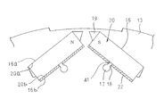
- FIG. 4 is an enlarged end view of a main part showing a rotor in a permanent magnet embedded type rotating electric machine according to Embodiment 2 of the present invention.
- the adhesive 22 applied to the inner wall surface 20 b is cured so as to form a gap from one end to the other end in the axial direction of the rotor core 13 on the magnet housing hole 16 side of the connection channel 18.
- the auxiliary refrigerant channel 41 is formed.
- Other configurations are the same as those in the first embodiment.
- the permanent magnet 20 having the adhesive 22 applied to the inner wall surface 20b is inserted into the magnet housing hole 16.
- an auxiliary refrigerant flow path forming mold (not shown) inserted into the refrigerant flow path 17 is protruded from the connection flow path 18 into the magnet housing hole 16, and the permanent magnet 20. Is pressed against the outer wall surface 16a.
- the auxiliary refrigerant flow path forming mold is pulled out. Thereby, the auxiliary refrigerant flow path 41 surrounded by the inner wall surface 20b of the permanent magnet 20 and the adhesive 22 is formed.
- the auxiliary refrigerant channel 41 is connected to the refrigerant channel 17 via the connection channel 18.
- the inner wall surface 20b of the permanent magnet 20 is exposed in the auxiliary refrigerant flow path 41, and the cooling oil flowing through the refrigerant flow path 17 and the connection flow path 18 also flows into the auxiliary refrigerant flow path 41. Touch. Further, the adhesive 22 for fixing the permanent magnet 20 is applied only between the inner wall surface 20 b of the permanent magnet 20 and the inner wall surface 16 b of the magnet housing hole 16. Therefore, also in the second embodiment, the same effect as in the first embodiment can be obtained.
- FIG. 5 is an enlarged end view of a main part showing a rotor in an embedded permanent magnet rotating electric machine according to Embodiment 3 of the present invention.
- the permanent magnet 20 is mounted in the magnet housing hole 16 with the outer wall surface 20 a fixed to the outer wall surface 16 a with an adhesive 22.
- a gap 42 is formed between the inner wall surface 20 b of the permanent magnet 20 and the inner wall surface 16 b of the magnet housing hole 16.
- Other configurations are the same as those in the first embodiment.
- the permanent magnet 20 having the adhesive 22 applied to the outer wall surface 20a is inserted into the magnet housing hole 16, and the rotor 11 is rotated before the adhesive 22 is cured. Thereby, the permanent magnet 20 is pressed against the outer wall surface 16a by centrifugal force, and a gap 42 is formed between the inner wall surfaces 20b and 16b. The gap 42 is retained by the curing of the adhesive 22.
- the cooling oil flowing through the refrigerant flow path 17 flows into the gap 42 between the inner wall surfaces 20b and 16b via the connection flow path 18. Thereby, the contact area of cooling oil and the permanent magnet 20 increases, and the permanent magnet 20 can be cooled effectively.
- FIG. 6 is an enlarged end view of a main part showing a rotor in an embedded permanent magnet rotating electric machine according to Embodiment 4 of the present invention.
- the rotor core 44 includes two core blocks 45 manufactured in the same shape.
- the iron core block 45 is configured in the same manner as the rotor iron core 13 except that the axial thickness is half. Then, the rotor core 44 rotates one core block 45 around the central axis O around the center axis O by one step skew angle ⁇ (mechanical angle) in the circumferential direction, and overlaps in the axial direction. It is constructed integrally. That is, the permanent magnets 49 housed in the magnet housing holes 46 of the iron core block 45 are configured in two stages in the axial direction, and the step skew angle ⁇ is set in the circumferential direction of the rotor core 44 between the two stages of the permanent magnets 49. Is provided.
- the step skew angle ⁇ satisfies Expression 2. It is set to be. Since the refrigerant channel 47 has a circular cross section, d is the radius of the refrigerant channel 47. ⁇ ⁇ sin ⁇ 1 (d / r) ⁇ ⁇ 2 (2)
- the step skew angle ⁇ is set so as to satisfy Expression 2
- a part of the refrigerant flow paths 47 of the two iron core blocks 45 overlap each other when viewed from the axial direction. Therefore, the refrigerant flow paths 47 of the two iron core blocks 45 are connected in the axial direction, and a refrigerant flow path is formed from one end of the rotor core 44 in the axial direction to the other end.
- the permanent magnet 49 is fixed to the outer wall surface 46 a of the magnet housing hole 46 by the adhesive 22 and attached to the iron core block 45.
- the permanent magnets 49 are provided in two stages in the axial direction, and a stage skew angle ⁇ is provided in the circumferential direction of the rotor core 44 between the stages of the permanent magnets 49. Therefore, the cogging torque can be reduced.
- the step skew angle ⁇ (mechanical angle) is set so as to satisfy Equation (2). Therefore, a part of the refrigerant flow path 47 of the two iron core blocks 45 overlaps when viewed from the axial direction, and a refrigerant flow path is formed from one end of the rotor core 44 in the axial direction to the other end. As a result, the cooling oil flowing through the refrigerant flow path flows into the connection flow path 48, contacts the permanent magnet 49, and cools the permanent magnet 49. Further, the adhesive 22 for fixing the permanent magnet 49 is applied only between the outer wall surface 49 a of the permanent magnet 49 and the outer wall surface 46 a of the magnet housing hole 46. Therefore, also in the fourth embodiment, the same effect as in the first embodiment can be obtained.
- the permanent magnets 49 are provided in two stages, and the step skew angle ⁇ is provided in the circumferential direction of the rotor core 44 between the stages of the permanent magnets.
- the step skew angle ⁇ may be provided in the circumferential direction of the rotor core 44 between each step of the permanent magnet.
- FIG. 7 is a sectional view showing a permanent magnet embedded rotary electric machine according to Embodiment 5 of the present invention.
- the in-axis flow path 33 ⁇ / b> A is formed to extend from one end in the axial direction to the axial center position of the shaft 12 ⁇ / b> A to a position below the introduction flow path 27 formed in the first end plate 25 in the radial direction.
- a branch channel 34 is formed in the shaft 12A so as to communicate the other axial end of the in-axis channel 33A with the introduction channel 27.
- Other configurations are the same as those in the first embodiment.
- the in-axis flow path 33A is formed only on the front side of the shaft 12A, so the cost of the shaft 12A can be reduced.
- the two permanent magnets constituting the magnetic pole are arranged in a V shape that is opened radially outward from the shaft.
- the arrangement of the permanent magnets is limited to this.
- the permanent magnets may be arranged at equiangular pitches in the circumferential direction so as to contact the same cylindrical surface, and each of the permanent magnets may constitute a magnetic pole.
- the permanent magnet has a rectangular cross section perpendicular to the axial direction of the shaft.
- the cross section of the permanent magnet is not limited to a rectangular shape, for example, an arc shape curved in an arc shape. Good.
- the magnet housing hole is formed in a cross-sectional shape that matches the cross-sectional shape of the permanent magnet.
Priority Applications (5)
| Application Number | Priority Date | Filing Date | Title |
|---|---|---|---|
| US15/032,175 US10116178B2 (en) | 2013-12-13 | 2013-12-13 | Rotor with embedded permanent magnet having adhesive on one side and cooling channels on the other side |
| EP13899228.4A EP3068021B1 (en) | 2013-12-13 | 2013-12-13 | Embedded permanent magnet-type rotating electrical machine |
| PCT/JP2013/083488 WO2015087445A1 (ja) | 2013-12-13 | 2013-12-13 | 永久磁石埋込型回転電機 |
| CN201380081558.0A CN105814779B (zh) | 2013-12-13 | 2013-12-13 | 永磁体埋入型旋转电机 |
| JP2015552271A JP6017067B2 (ja) | 2013-12-13 | 2013-12-13 | 永久磁石埋込型回転電機 |
Applications Claiming Priority (1)
| Application Number | Priority Date | Filing Date | Title |
|---|---|---|---|
| PCT/JP2013/083488 WO2015087445A1 (ja) | 2013-12-13 | 2013-12-13 | 永久磁石埋込型回転電機 |
Publications (1)
| Publication Number | Publication Date |
|---|---|
| WO2015087445A1 true WO2015087445A1 (ja) | 2015-06-18 |
Family
ID=53370786
Family Applications (1)
| Application Number | Title | Priority Date | Filing Date |
|---|---|---|---|
| PCT/JP2013/083488 WO2015087445A1 (ja) | 2013-12-13 | 2013-12-13 | 永久磁石埋込型回転電機 |
Country Status (5)
| Country | Link |
|---|---|
| US (1) | US10116178B2 (zh) |
| EP (1) | EP3068021B1 (zh) |
| JP (1) | JP6017067B2 (zh) |
| CN (1) | CN105814779B (zh) |
| WO (1) | WO2015087445A1 (zh) |
Cited By (11)
| Publication number | Priority date | Publication date | Assignee | Title |
|---|---|---|---|---|
| WO2017170982A1 (ja) * | 2016-03-31 | 2017-10-05 | アイシン・エィ・ダブリュ株式会社 | 回転電機用ロータ |
| JP2017184351A (ja) * | 2016-03-29 | 2017-10-05 | 三菱電機株式会社 | 回転電機 |
| CN107645221A (zh) * | 2016-07-20 | 2018-01-30 | 通用电气航空系统有限责任公司 | 发电机的方法和组装 |
| WO2018173104A1 (ja) * | 2017-03-21 | 2018-09-27 | 三菱電機株式会社 | 電動機および送風装置 |
| JP2018161001A (ja) * | 2017-03-23 | 2018-10-11 | 本田技研工業株式会社 | Ipmロータおよび回転電機 |
| WO2020049972A1 (ja) * | 2018-09-03 | 2020-03-12 | 株式会社Ihi | 過給機用埋込永久磁石型モータ |
| JP2020120425A (ja) * | 2019-01-18 | 2020-08-06 | 本田技研工業株式会社 | ロータ |
| JP2020198706A (ja) * | 2019-06-03 | 2020-12-10 | 本田技研工業株式会社 | 回転電機 |
| US11043863B2 (en) | 2016-03-31 | 2021-06-22 | Aisin Aw Co., Ltd. | Rotor manufacturing method |
| JP2021170877A (ja) * | 2020-04-16 | 2021-10-28 | 三菱電機株式会社 | 回転電機 |
| JP2022542441A (ja) * | 2019-08-01 | 2022-10-03 | シェフラー テクノロジーズ アー・ゲー ウント コー. カー・ゲー | 自動車用の電気駆動ユニット、ハイブリッドモジュールおよび駆動装置 |
Families Citing this family (40)
| Publication number | Priority date | Publication date | Assignee | Title |
|---|---|---|---|---|
| JP6405788B2 (ja) * | 2014-08-20 | 2018-10-17 | 株式会社デンソー | 回転電機の回転子 |
| JP6297216B2 (ja) | 2015-05-15 | 2018-03-20 | 三菱電機株式会社 | 回転電機 |
| JP2017070040A (ja) * | 2015-09-29 | 2017-04-06 | アイシン精機株式会社 | 三相回転電機 |
| DE102016200423A1 (de) * | 2016-01-15 | 2017-07-20 | Continental Automotive Gmbh | Elektrische Maschine |
| JP6298086B2 (ja) * | 2016-02-24 | 2018-03-20 | ファナック株式会社 | 電動機のロータ及びその製造方法 |
| DE102016204794A1 (de) * | 2016-03-23 | 2017-09-28 | Thyssenkrupp Ag | Rotorsegment einer elektrischen Maschine |
| DE102017201117A1 (de) * | 2017-01-24 | 2018-07-26 | Bayerische Motoren Werke Aktiengesellschaft | Verfahren zum Kühlen einer elektrischen Maschine sowie elektrische Maschine |
| US10594191B2 (en) * | 2017-03-27 | 2020-03-17 | Ford Global Technologies, Llc | Rotor endplate for electric machine |
| CN106972666B (zh) * | 2017-04-27 | 2019-06-14 | 哈尔滨工业大学 | 一种油冷、低耗外转子永磁电机 |
| DE102017112348A1 (de) * | 2017-06-06 | 2018-12-06 | Dr. Ing. H.C. F. Porsche Aktiengesellschaft | Elektrische Maschine |
| WO2019008820A1 (ja) * | 2017-07-05 | 2019-01-10 | 三菱電機株式会社 | 回転電機 |
| JP6548276B2 (ja) * | 2017-10-04 | 2019-07-24 | 本田技研工業株式会社 | 回転電機のロータ |
| CN111418132A (zh) * | 2017-12-07 | 2020-07-14 | 三菱电机株式会社 | 转子、电动机、压缩机、空气调节机以及转子的制造方法 |
| JP6688327B2 (ja) * | 2018-01-30 | 2020-04-28 | 本田技研工業株式会社 | 回転電機のロータ |
| JP7027187B2 (ja) * | 2018-02-05 | 2022-03-01 | 株式会社日立産機システム | 外転型永久磁石回転電機 |
| CN108539889A (zh) * | 2018-03-30 | 2018-09-14 | 合肥巨动力系统有限公司 | 一种永磁同步电机转子风冷结构 |
| CN108539888A (zh) * | 2018-03-30 | 2018-09-14 | 合肥巨动力系统有限公司 | 一种永磁同步电机转子散热结构 |
| JP7061001B2 (ja) * | 2018-04-05 | 2022-04-27 | 株式会社Soken | 回転電機ユニット |
| US11031834B2 (en) * | 2018-04-12 | 2021-06-08 | Ford Global Technologies, Llc | Electric machine rotor end plate with raised flow features |
| JP2019216532A (ja) * | 2018-06-12 | 2019-12-19 | 本田技研工業株式会社 | 回転電機のロータ |
| CN110690775B (zh) * | 2018-07-05 | 2021-11-19 | 爱信艾达株式会社 | 转子以及旋转电机 |
| US11121597B2 (en) * | 2018-08-08 | 2021-09-14 | Schaeffler Technologies AG & Co. KG | Hybrid module including rotor having coolant flow channels |
| JPWO2020067348A1 (ja) * | 2018-09-28 | 2021-08-30 | 本田技研工業株式会社 | 回転電機のロータ |
| CN113424398A (zh) * | 2019-03-27 | 2021-09-21 | 大金工业株式会社 | 电动机 |
| DE102019204960A1 (de) * | 2019-04-08 | 2020-10-08 | Audi Ag | Rotor für eine elektrische Maschine |
| DE102019109721A1 (de) * | 2019-04-12 | 2020-10-15 | Dr. Ing. H.C. F. Porsche Aktiengesellschaft | Rotor für eine elektrische Maschine |
| JP7093745B2 (ja) * | 2019-05-17 | 2022-06-30 | 本田技研工業株式会社 | 電動モータのロータ構造 |
| US11515756B2 (en) * | 2020-03-27 | 2022-11-29 | Dana Belgium N.V. | Electric motor cooling system |
| DE102020112896A1 (de) | 2020-05-13 | 2021-11-18 | Schaeffler Technologies AG & Co. KG | Elektrische Rotationsmaschine und Antriebssystem für ein Kraftfahrzeug |
| US20220263384A1 (en) * | 2021-02-18 | 2022-08-18 | Shreyas Kapatral | Thermal management techniques for electric motors |
| US11545860B2 (en) | 2021-02-22 | 2023-01-03 | GM Global Technology Operations LLC | Inserts for motor rotor core |
| US11770039B2 (en) * | 2021-03-15 | 2023-09-26 | GM Global Technology Operations LLC | Rotor cooling with heat conductive material |
| CN113141074B (zh) * | 2021-04-09 | 2023-07-18 | 浙江零跑科技股份有限公司 | 一种永磁同步电动机的转子结构及其制造方法 |
| US11646620B2 (en) | 2021-04-14 | 2023-05-09 | GM Global Technology Operations LLC | Preloading magnets in a rotor core |
| DE102021207594A1 (de) * | 2021-07-16 | 2023-01-19 | Magna powertrain gmbh & co kg | Elektrische Maschine |
| US11777348B2 (en) | 2021-08-03 | 2023-10-03 | GM Global Technology Operations LLC | Rotor core with load bearing polymer and insert |
| DE102022111413A1 (de) | 2022-05-09 | 2023-11-09 | Bayerische Motoren Werke Aktiengesellschaft | Rotor für eine elektrische Traktionsmaschine eines Kraftfahrzeugs sowie elektrische Traktionsmaschine |
| DE102022205857A1 (de) | 2022-06-09 | 2023-12-14 | Robert Bosch Gesellschaft mit beschränkter Haftung | Rotor einer elektrischen Maschine |
| WO2024034407A1 (en) * | 2022-08-11 | 2024-02-15 | Mitsubishi Heavy Industries, Ltd. | Electric machines and related methods of operation |
| WO2024034408A1 (en) * | 2022-08-11 | 2024-02-15 | Mitsubishi Heavy Industries, Ltd. | Heat exchangers for electric machines and related methods of operation |
Citations (5)
| Publication number | Priority date | Publication date | Assignee | Title |
|---|---|---|---|---|
| JP2013017297A (ja) | 2011-07-04 | 2013-01-24 | Toyota Motor Corp | 回転電機のロータ |
| JP2013183480A (ja) * | 2012-02-29 | 2013-09-12 | Toyota Motor Corp | 回転電機用ロータの冷却構造、および、回転電機 |
| JP2013183483A (ja) * | 2012-02-29 | 2013-09-12 | Toyota Motor Corp | 回転電機用ロータの冷却構造、および、回転電機 |
| WO2013136405A1 (ja) * | 2012-03-12 | 2013-09-19 | トヨタ自動車株式会社 | 回転電機 |
| JP2013192339A (ja) * | 2012-03-13 | 2013-09-26 | Toyota Industries Corp | 誘導電動機 |
Family Cites Families (14)
| Publication number | Priority date | Publication date | Assignee | Title |
|---|---|---|---|---|
| EP1641103B1 (en) | 1997-10-13 | 2008-08-20 | Matsushita Electric Industrial Co., Ltd. | A motor using a rotor including interior permanent magnets |
| US7705503B2 (en) * | 2005-09-07 | 2010-04-27 | Kabushiki Kaisha Toshiba | Rotating electrical machine |
| EP1953896B1 (en) * | 2005-11-09 | 2016-10-19 | Kabushiki Kaisha Toshiba | Rotor for electric rotating machine and electric rotating machine |
| JP4363479B2 (ja) * | 2007-11-09 | 2009-11-11 | トヨタ自動車株式会社 | 回転電機および駆動装置 |
| JP5433198B2 (ja) * | 2008-10-16 | 2014-03-05 | 日立オートモティブシステムズ株式会社 | 回転電機及び電気自動車 |
| US8022582B2 (en) * | 2008-12-30 | 2011-09-20 | Caterpillar Inc. | Liquid cooled permanent magnet rotor |
| JP5490103B2 (ja) * | 2009-04-17 | 2014-05-14 | 株式会社日本自動車部品総合研究所 | 回転電機 |
| JP5581013B2 (ja) | 2009-06-23 | 2014-08-27 | 株式会社三井ハイテック | 回転子鉄心 |
| WO2011132784A1 (ja) | 2010-04-23 | 2011-10-27 | 株式会社Ihi | 回転機 |
| JP5673327B2 (ja) | 2010-05-12 | 2015-02-18 | 株式会社デンソー | 回転電機の回転子 |
| WO2011158316A1 (ja) * | 2010-06-14 | 2011-12-22 | トヨタ自動車株式会社 | 回転電機用ロータコアおよびその製造方法 |
| US20120299403A1 (en) * | 2011-05-26 | 2012-11-29 | Stahlhut Ronnie D | Method and apparatus for cooling an electrical motor rotor |
| JP2013230047A (ja) | 2012-04-26 | 2013-11-07 | Ichinomiya Denki:Kk | モータ用ロータ、及びモータ |
| CN203104159U (zh) | 2013-01-24 | 2013-07-31 | 艾默生环境优化技术(苏州)有限公司 | 一种转子以及包含该转子的电动机和压缩机 |
-
2013
- 2013-12-13 JP JP2015552271A patent/JP6017067B2/ja active Active
- 2013-12-13 CN CN201380081558.0A patent/CN105814779B/zh active Active
- 2013-12-13 EP EP13899228.4A patent/EP3068021B1/en active Active
- 2013-12-13 WO PCT/JP2013/083488 patent/WO2015087445A1/ja active Application Filing
- 2013-12-13 US US15/032,175 patent/US10116178B2/en active Active
Patent Citations (5)
| Publication number | Priority date | Publication date | Assignee | Title |
|---|---|---|---|---|
| JP2013017297A (ja) | 2011-07-04 | 2013-01-24 | Toyota Motor Corp | 回転電機のロータ |
| JP2013183480A (ja) * | 2012-02-29 | 2013-09-12 | Toyota Motor Corp | 回転電機用ロータの冷却構造、および、回転電機 |
| JP2013183483A (ja) * | 2012-02-29 | 2013-09-12 | Toyota Motor Corp | 回転電機用ロータの冷却構造、および、回転電機 |
| WO2013136405A1 (ja) * | 2012-03-12 | 2013-09-19 | トヨタ自動車株式会社 | 回転電機 |
| JP2013192339A (ja) * | 2012-03-13 | 2013-09-26 | Toyota Industries Corp | 誘導電動機 |
Non-Patent Citations (1)
| Title |
|---|
| See also references of EP3068021A4 |
Cited By (19)
| Publication number | Priority date | Publication date | Assignee | Title |
|---|---|---|---|---|
| JP2017184351A (ja) * | 2016-03-29 | 2017-10-05 | 三菱電機株式会社 | 回転電機 |
| US11043863B2 (en) | 2016-03-31 | 2021-06-22 | Aisin Aw Co., Ltd. | Rotor manufacturing method |
| US10658892B2 (en) | 2016-03-31 | 2020-05-19 | Aisin Aw Co., Ltd. | Rotor for rotating electrical machine |
| CN108886278B (zh) * | 2016-03-31 | 2020-08-28 | 爱信艾达株式会社 | 旋转电机用转子 |
| WO2017170982A1 (ja) * | 2016-03-31 | 2017-10-05 | アイシン・エィ・ダブリュ株式会社 | 回転電機用ロータ |
| JPWO2017170982A1 (ja) * | 2016-03-31 | 2018-11-01 | アイシン・エィ・ダブリュ株式会社 | 回転電機用ロータ |
| CN108886278A (zh) * | 2016-03-31 | 2018-11-23 | 爱信艾达株式会社 | 旋转电机用转子 |
| CN107645221A (zh) * | 2016-07-20 | 2018-01-30 | 通用电气航空系统有限责任公司 | 发电机的方法和组装 |
| WO2018173104A1 (ja) * | 2017-03-21 | 2018-09-27 | 三菱電機株式会社 | 電動機および送風装置 |
| US11509194B2 (en) | 2017-03-21 | 2022-11-22 | Mitsubishi Electric Corporation | Motor with rotor and endplates with blade parts and cooling hole |
| JP2018161001A (ja) * | 2017-03-23 | 2018-10-11 | 本田技研工業株式会社 | Ipmロータおよび回転電機 |
| WO2020049972A1 (ja) * | 2018-09-03 | 2020-03-12 | 株式会社Ihi | 過給機用埋込永久磁石型モータ |
| JPWO2020049972A1 (ja) * | 2018-09-03 | 2021-08-26 | 株式会社Ihi | 過給機用埋込永久磁石型モータ |
| JP2020120425A (ja) * | 2019-01-18 | 2020-08-06 | 本田技研工業株式会社 | ロータ |
| JP2020198706A (ja) * | 2019-06-03 | 2020-12-10 | 本田技研工業株式会社 | 回転電機 |
| US11309758B2 (en) | 2019-06-03 | 2022-04-19 | Honda Motor Co., Ltd. | Rotating electric machine |
| JP7284343B2 (ja) | 2019-08-01 | 2023-05-30 | シェフラー テクノロジーズ アー・ゲー ウント コー. カー・ゲー | 自動車用の電気駆動ユニット、ハイブリッドモジュールおよび駆動装置 |
| JP2022542441A (ja) * | 2019-08-01 | 2022-10-03 | シェフラー テクノロジーズ アー・ゲー ウント コー. カー・ゲー | 自動車用の電気駆動ユニット、ハイブリッドモジュールおよび駆動装置 |
| JP2021170877A (ja) * | 2020-04-16 | 2021-10-28 | 三菱電機株式会社 | 回転電機 |
Also Published As
| Publication number | Publication date |
|---|---|
| EP3068021A1 (en) | 2016-09-14 |
| JP6017067B2 (ja) | 2016-10-26 |
| EP3068021A4 (en) | 2017-07-19 |
| US20160261158A1 (en) | 2016-09-08 |
| EP3068021B1 (en) | 2018-08-29 |
| JPWO2015087445A1 (ja) | 2017-03-16 |
| US10116178B2 (en) | 2018-10-30 |
| CN105814779A (zh) | 2016-07-27 |
| CN105814779B (zh) | 2018-05-08 |
Similar Documents
| Publication | Publication Date | Title |
|---|---|---|
| JP6017067B2 (ja) | 永久磁石埋込型回転電機 | |
| JP6174150B2 (ja) | 永久磁石埋込型回転電機 | |
| EP1953896B1 (en) | Rotor for electric rotating machine and electric rotating machine | |
| JP6269600B2 (ja) | 回転電機のロータ | |
| JP5470015B2 (ja) | 回転電機 | |
| JP7078360B2 (ja) | ロータコア | |
| JP6297216B2 (ja) | 回転電機 | |
| JP6079733B2 (ja) | 回転電機のロータ | |
| CN110247497B (zh) | 旋转电机的转子 | |
| JP2007104888A (ja) | 回転電機 | |
| JP2012235546A (ja) | ロータおよび回転電機 | |
| JP5549857B2 (ja) | 回転電機用ロータ | |
| US20190181708A1 (en) | Rotary electrical machine | |
| CN110176818B (zh) | 旋转电机的转子 | |
| JP2017046545A (ja) | 回転電機用ロータ | |
| JP2015177706A (ja) | 回転電機のロータ構造 | |
| JP5656758B2 (ja) | 回転電機 | |
| JP5392012B2 (ja) | 電動機 | |
| JP2009027800A (ja) | モータの冷却構造 | |
| JP2011193623A (ja) | 回転電機 | |
| JP2016129447A (ja) | 回転電機 | |
| JP5330860B2 (ja) | 回転電機 | |
| JP2016059190A (ja) | 回転電機のロータ | |
| JP6875350B2 (ja) | 回転電機 | |
| CN102882296A (zh) | 旋转电机 |
Legal Events
| Date | Code | Title | Description |
|---|---|---|---|
| 121 | Ep: the epo has been informed by wipo that ep was designated in this application |
Ref document number: 13899228 Country of ref document: EP Kind code of ref document: A1 |
|
| ENP | Entry into the national phase |
Ref document number: 2015552271 Country of ref document: JP Kind code of ref document: A |
|
| WWE | Wipo information: entry into national phase |
Ref document number: 15032175 Country of ref document: US |
|
| REEP | Request for entry into the european phase |
Ref document number: 2013899228 Country of ref document: EP |
|
| WWE | Wipo information: entry into national phase |
Ref document number: 2013899228 Country of ref document: EP |
|
| NENP | Non-entry into the national phase |
Ref country code: DE |