WO2015083495A1 - 電子機器 - Google Patents
電子機器 Download PDFInfo
- Publication number
- WO2015083495A1 WO2015083495A1 PCT/JP2014/079678 JP2014079678W WO2015083495A1 WO 2015083495 A1 WO2015083495 A1 WO 2015083495A1 JP 2014079678 W JP2014079678 W JP 2014079678W WO 2015083495 A1 WO2015083495 A1 WO 2015083495A1
- Authority
- WO
- WIPO (PCT)
- Prior art keywords
- user
- unit
- information
- article
- control unit
- Prior art date
- Legal status (The legal status is an assumption and is not a legal conclusion. Google has not performed a legal analysis and makes no representation as to the accuracy of the status listed.)
- Ceased
Links
Images






Classifications
-
- G—PHYSICS
- G06—COMPUTING OR CALCULATING; COUNTING
- G06Q—INFORMATION AND COMMUNICATION TECHNOLOGY [ICT] SPECIALLY ADAPTED FOR ADMINISTRATIVE, COMMERCIAL, FINANCIAL, MANAGERIAL OR SUPERVISORY PURPOSES; SYSTEMS OR METHODS SPECIALLY ADAPTED FOR ADMINISTRATIVE, COMMERCIAL, FINANCIAL, MANAGERIAL OR SUPERVISORY PURPOSES, NOT OTHERWISE PROVIDED FOR
- G06Q30/00—Commerce
- G06Q30/02—Marketing; Price estimation or determination; Fundraising
-
- G—PHYSICS
- G06—COMPUTING OR CALCULATING; COUNTING
- G06Q—INFORMATION AND COMMUNICATION TECHNOLOGY [ICT] SPECIALLY ADAPTED FOR ADMINISTRATIVE, COMMERCIAL, FINANCIAL, MANAGERIAL OR SUPERVISORY PURPOSES; SYSTEMS OR METHODS SPECIALLY ADAPTED FOR ADMINISTRATIVE, COMMERCIAL, FINANCIAL, MANAGERIAL OR SUPERVISORY PURPOSES, NOT OTHERWISE PROVIDED FOR
- G06Q30/00—Commerce
- G06Q30/06—Buying, selling or leasing transactions
-
- G—PHYSICS
- G07—CHECKING-DEVICES
- G07G—REGISTERING THE RECEIPT OF CASH, VALUABLES, OR TOKENS
- G07G1/00—Cash registers
- G07G1/12—Cash registers electronically operated
- G07G1/14—Systems including one or more distant stations co-operating with a central processing unit
Definitions
- the present invention relates to an electronic device.
- the present invention has been made in view of the above-described problems, and an object thereof is to provide an easy-to-use electronic device.
- the electronic apparatus of the present invention includes a first input unit that inputs operation information related to user purchase, and a second input unit that inputs biometric information related to the user purchase.
- a detection unit may be provided that detects the degree of satisfaction or dissatisfaction of the user based on information input by the first input unit and the second input unit. Moreover, you may provide the instruction
- the first input unit may input information regarding the movement of the user's hand.
- the second input unit may input the user's biological information used for estimating emotion information related to the user's purchase.
- the first input unit and the second input unit may input information about the eyes from the user side.
- you may provide the communication part which can communicate with the acquisition apparatus which acquires the information regarding the eye from the said user side.
- the communication unit may communicate with a communication unit provided in the acquisition device.
- the said communication part is good also as communicating with the said acquisition apparatus via the communication relay apparatus different from the said acquisition apparatus.
- the communication unit may communicate with the acquisition device via proximity communication or human body communication with the communication relay device.
- the acquisition apparatus may include an imaging unit that performs imaging, and an analysis unit that analyzes imaging data captured by the imaging unit.
- the first input unit may input the operation information in response to a change in the biological information input by the second input unit.
- An electronic apparatus includes an input unit that inputs information about eyes from a user side, and an estimation unit that estimates emotion information about purchase of the user based on information about eyes from the user side. .
- the estimation unit may estimate emotion information related to the user's purchase based on whether or not the information related to the eyes from the user side matches or resembles a predetermined pattern.
- the electronic device of the present invention includes a speed acquisition unit that acquires the moving speed of the user, and the estimation unit acquires and acquires information input to the input unit according to the moving speed of the user. The estimation may be performed based on the information.
- An electronic device is an electronic device that can be worn near a user's face, and obtains information related to eyes from the user side, and information obtained by the obtaining unit via human body communication.
- a communication unit that communicates with an external device in contact with the user.
- a speed acquisition unit that acquires the moving speed of the user may be provided, and the communication unit may transmit the information acquired by the acquiring unit to the external device according to the moving speed of the user. Good.
- the electronic device includes an input unit that inputs information on the article in response to at least one of the article being picked up by the user and the article being in a predetermined range within the user's field of view; A notification unit for performing notification regarding the information on the article input by the unit.
- the first control for limiting the information notified by the notification unit May be provided.
- the first control unit varies the information notified by the notification unit according to the number of times the item is picked up or the number of times the item enters a predetermined range within the field of view of the user. It is good.
- the second control for restricting information notified by the notification unit when the user picks up a similar article similar to the article or when the similar article enters a predetermined range within the field of view of the user. May be provided.
- the input unit inputs information on a product scheduled to be purchased by the user as information on the product, and the notification unit notifies information on the product planned to be purchased. Also good.
- the input unit may input information on the commodity scheduled to be purchased from an external device.
- the input unit may input information corresponding to the product scheduled for purchase from the external device via a storage device that stores the product scheduled for purchase.
- the notification unit may include at least one of a display unit that performs display and an audio output unit that outputs sound.
- the sound output unit may be a sound output unit having directivity.
- the electronic device of the present invention may include a mounting portion that can be mounted near the user's face.
- the present invention has an effect that it is possible to provide a user-friendly electronic device.
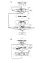
- FIG. 4A is a flowchart showing processing of the mounting device according to the first embodiment
- FIG. 4B is a flowchart showing processing of the article device according to the first embodiment.
- FIG. 7A and FIG. 7B are diagrams (part 1) illustrating an example of a line-of-sight image.
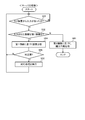
- FIG. 11A is a flowchart showing processing of the mounting device according to the second embodiment
- FIG. 11B is a flowchart showing processing of the article device according to the second embodiment.
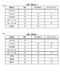
- FIG. 14A and FIG. 14B are diagrams illustrating an example of the shopping DB.
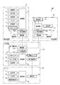
- FIG. 1 is a block diagram showing the configuration of an electronic device system 100 according to the first embodiment.
- the electronic device system 100 includes a mounting device 10, a basket device 20, an article device 30, and a server 40, as shown in FIG.
- the wearing device 10 is a glasses-type terminal that is worn on the face by a user (shopper) visiting the store.
- the basket device 20 is a device provided in the basket 120 installed in the store.
- the article device 30 is an apparatus provided in an article (product) 130 displayed in the store.
- the server 40 is an information processing apparatus provided in a store or a data center. Communication between the mounting device 10 and the basket device 20 and between the article device 30 and the basket device 20 is possible via a human body (human body communication), and between the basket device 20 and the server 40. Wireless communication is possible.
- the mounting device 10 includes an imaging unit 11, a display unit 12, an operation unit 13, a microphone 14, a storage unit 15, a communication unit 16, and a control unit 17.
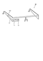
- the mounting device 10 is shown in a perspective view.
- the mounting apparatus 10 includes a glasses-type frame 110. The configuration of the mounting device 10 illustrated in FIG. 1 and not illustrated in FIG. 3 is provided inside the frame 110 or a part of the frame 110.
- the imaging unit 11 includes a lens, an imaging device, an image processing unit, and the like, and captures still images and moving images. As shown in FIG. 3, the imaging unit 11 is provided near the end of the frame 110 (near the user's right eye). For this reason, in a state where the user wears the mounting apparatus 10 (the state shown in FIG. 2), an image in a direction in which the user is facing (viewing) can be taken. In addition, a predetermined portion (for example, a portion slightly deviated to the left from the center) of the captured image can be regarded as a portion where the user is turning his / her line of sight (a portion being watched).
- the display unit 12 includes a projector provided in or near the frame 110, and a prism for guiding a projection image from the projector to the eyes of the user.
- the display unit 12 displays various information under the instruction of the control unit 17.
- the operation unit 13 is a touch pad provided on the frame 110, detects the movement of the user's finger, receives an operation from the user, and transmits the received operation information to the control unit 17.
- the details of the imaging unit 11, the display unit 12, and the operation unit 13 are also disclosed in, for example, US Published Patent No. 2013/0044042.
- the microphone 14 is provided in the frame 110 and collects voices uttered by the user and voices around the user.
- the voice collected by the microphone 14 is voice-recognized by a voice recognition unit (not shown), and the voice recognition result is transmitted to the control unit 17.
- the control unit 17 executes processing based on the voice recognition result (for example, command execution processing).
- the control unit 17 may perform voice recognition. Further, the control unit 17 stores the collected audio data in the storage unit 15.
- the storage unit 15 is, for example, a non-volatile semiconductor memory such as a flash memory, and stores image data captured by the imaging unit 11, audio data collected by the microphone 14, display data displayed on the display unit 12, and the like. .
- the communication unit 16 performs human body communication with other devices.
- the communication unit 16 includes an electrode unit 16a that is provided on the frame 110 and can contact a user, and a human body communication unit 16b that performs human body communication using the electrode unit 16a.
- Human body communication includes a current system in which a weak current is passed through the human body and the current is modulated to transmit information, and an electric field system in which information is transmitted by modulating an electric field induced on the surface of the human body. . In this embodiment, it is possible to use either the current method or the electric field method. Note that human body communication is possible not only when the user directly contacts the electrode portion 16a of the mounting apparatus 10, but also when the user does not directly contact the electrode portion 16a and the user.
- the communication unit 16 transmits image data captured by the imaging unit 11 and audio data collected by the microphone 14 to the basket device 20.
- the communication unit 16 may perform near field communication such as Bluetooth (registered trademark), RFID (Radio Frequency Identification), Transfer Jet (registered trademark), or the like with other devices.
- the mounting device 10 may have a wireless communication unit instead of the communication unit 16 or in combination with the communication unit 16.
- image data and sound data may be directly transmitted to the server 40 by wireless communication, or image data and sound data may be transmitted to the basket device 20 by wireless communication.
- the control unit 17 comprehensively controls the entire mounting device 10.
- the control unit 17 includes a CPU (Central Processing Unit), a RAM (Random Access Memory), a ROM (Read Only Memory), and the like.
- the control unit 17 performs control related to imaging of the imaging unit 11, control related to display of the display unit 12, and the like.
- the mounting device 10 may not be a glasses-type terminal.
- it may be a wearable terminal that can be worn at any position on the body, and some of its functions may be separated.
- a wristwatch type terminal may have other functions as a contact lens type terminal provided with a display unit.
- the basket device 20 includes a biological sensor 21, a calendar unit 22, a storage unit 23, a first communication unit 24, a second communication unit 25, a control unit 26, and the like.
- the biosensor 21 is provided in a portion of the cage 120 that is touched by a hand when the user holds the cage 120 (a handle portion).
- the biological sensor 21 detects changes in biological information of the body such as heart rate, blood pressure, and sweating amount, and includes, for example, an LED (Light Emitting Diode), a photo sensor, and a sweat sensor.
- an LED Light Emitting Diode
- a photo sensor e.g., a photo sensor
- a sweat sensor can detect the amount of sweat by measuring the impedance of the hand with a plurality of electrodes.
- the output from the biosensor 21 is sent to the control unit 26. Then, the control unit 26 estimates a change in the user's emotion (feeling emotional) based on the output of the biological sensor 21.
- the calendar unit 22 acquires time information such as year, month, day, and time and outputs the time information to the control unit 26.
- the calendar unit 22 measures time.
- the storage unit 23 is, for example, a non-volatile semiconductor memory such as a flash memory, and stores information related to an article obtained by the user as will be described later. Further, the storage unit 23 stores an ID number (cage ID) for uniquely identifying the basket device 20.
- an ID number (cage ID) for uniquely identifying the basket device 20.
- the first communication unit 24 performs human body communication with other devices. Note that the first communication unit 24 may perform near field communication with other devices. In the present embodiment, the first communication unit 24 communicates with the communication unit 16 of the mounting device 10 and the communication unit 32 of the object device 30 using human body communication.
- the first communication unit 24 includes an electrode unit 24a that is provided on the handle portion of the cage 120 and that can contact the user's hand or arm, and a human body communication unit 24b that performs human body communication via the electrode unit 24a. .
- the second communication unit 25 performs wireless communication with other devices.
- wireless communication with the server 40 is performed, and article information of an article touched by the user, image data captured by the imaging unit 11, audio data collected by the microphone 14, and detection of the biosensor 21 The result is transmitted to the server 40.
- the basket device 20 of the present embodiment is a communication relay device that relays communication of article information between the article device 30 and the server 40 and communication of image data and audio data between the mounting device 10 and the server 40. As a function.
- the control unit 26 controls the entire basket device 20 and includes a CPU, a RAM, a ROM, and the like. In the present embodiment, the control unit 26 controls information communication with the article device 30, the mounting device 10, and the server 40.
- the basket device 20 may be provided in a cart used in a store. In this case, it is preferable that the biosensor 21 and the electrode portion 24a of the first communication unit 24 are provided in the grip portion of the cart.
- the article device 30 is an article (product) sold in a store or the like, and is provided on an article that comes into contact with the body of a visitor (user), such as food, clothes, shoes, watches, accessories, golf clubs, and bags. .
- a visitor such as food, clothes, shoes, watches, accessories, golf clubs, and bags.
- the article device 30 will be described as being provided on a product (foodstuff or the like) displayed in a supermarket.
- the article device 30 includes a storage unit 31, a communication unit 32, and a control unit 33, as shown in FIG.
- the storage unit 31 is, for example, a non-volatile semiconductor memory such as a flash memory, and stores information on an article (product) to which the article device 30 is attached. Specifically, the storage unit 31 stores article information (product information) of an article to which the article device 30 is attached. For example, when the article device 30 is attached to a processed food (for example, canned food), the storage unit 31 includes, as article information, a manufacturer (seller), a product name, a raw material name, an expiration date, an internal capacity, Remember the country.
- a manufacturer for example, canned food
- the storage unit 31 includes, as article information, a manufacturer (seller), a product name, a raw material name, an expiration date, an internal capacity, Remember the country.
- the control unit 33 controls the entire article device 30 and includes a CPU, a RAM, a ROM, and the like. In the present embodiment, the control unit 33 controls transmission of the article information stored in the storage unit 31 to the basket device 20.
- the control unit 33 and the storage unit 31 may be provided at any position of the article.
- the communication unit 32 performs human body communication with other devices.
- the communication unit 32 may perform near field communication with other devices.
- the communication part 32 is provided with the electrode part 32a provided in the position which contacts a user (for example, hand), and the human body communication part 32b which performs human body communication using the electrode part 32a.
- the human body between the first communication unit 24 of the basket device 20 and the communication unit 32 of the product device 30 with the user holding the basket 120 in the hand. Communication is established. Thereby, the article information stored in the storage unit 31 is transmitted to the basket device 20.
- human body communication is possible not only when the user directly contacts the electrode part 32a of the article device 30, but also when the electrode part 32a and the user are not in direct contact (such as when wearing gloves).
- the server 40 includes a storage unit 41, a communication unit 42, an OCR (Optical Character Reader) unit 43, an image recognition unit 44, and a control unit 46.
- OCR Optical Character Reader
- the storage unit 41 is, for example, a nonvolatile semiconductor memory such as a flash memory, a hard disk drive, or the like, and stores information acquired from the basket device 20, that is, image data captured by the imaging unit 11 of the mounting device 10 and the microphone 14. The voice data collected by use and the article information transmitted from the article device 30 are stored. In addition, the storage unit 41 stores face image data and product image data of store employees (store clerk) and various data used when analyzing user purchase behavior. In the present embodiment, as will be described later, the control unit 46 cooperates with the image recognition unit 44 to determine whether the image data captured by the imaging unit 11 of the mounting apparatus 10 includes the employee's face or product. Is detected.
- the communication unit 42 performs wireless communication with other devices.
- the communication unit 42 performs wireless communication with the second communication unit 25 of the basket device 20 by wireless communication.
- the OCR unit 43 recognizes characters included in the image data captured by the imaging unit 11 of the mounting apparatus 10 and converts them into text data. For example, when the imaging unit 11 captures the image data of FIG. 7B, the OCR unit 43 recognizes the character and the text data “Sorry. Currently waiting for arrival. The next arrival time is undecided. Is obtained.
- the image recognizing unit 44 extracts feature points of image data captured by the imaging unit 11 of the mounting apparatus 10 using, for example, a feature amount detection algorithm such as SURF (Speeded Up Up Robust Features) or SIFT (Scale Invariant Feature Up Transform), and a storage unit Image recognition is performed by comparing with a plurality of recognition target standard patterns stored in 41.
- a feature amount detection algorithm such as SURF (Speeded Up Up Robust Features) or SIFT (Scale Invariant Feature Up Transform)
- a storage unit Image recognition is performed by comparing with a plurality of recognition target standard patterns stored in 41.
- the image recognition unit 44 compares the employee's face image data and product image data stored in the storage unit 41, and the employee and the product are included in the image captured by the imaging unit 11. Detect whether it is included.
- the control unit 46 controls the entire server 40 and includes a CPU, a RAM, a ROM, and the like.
- the processing of the electronic device system 100 will be described in detail with reference to FIGS.
- a user shopper wearing the mounting apparatus 10 visits a store (for example, a supermarket)
- the basket 120 is held and shopping is performed.
- the user determines an article to be purchased by picking up an article (product) 130 provided with the article device 30 in the store or putting it in the basket 120, and performs purchase processing at a cash register. To do.
- FIG. 4A shows the processing of the mounting apparatus 10 in a flowchart.
- step S10 the control unit 17 of the mounting device 10 waits until human body communication with the basket device 20 is established in step S10.
- the control unit 17 proceeds to step S12.
- the process from step S12 may be executed when the user turns on the power of the mounting apparatus 10 after entering the store.
- the mounting device 10 is provided with a position detection device capable of detecting a position according to a communication state with a GPS (Global Positioning System) module or a wireless LAN (Local Area Network) base station installed in the store,
- the control unit 17 may determine whether the user has entered the store based on the detection result of the position detection device.
- the mounting apparatus 10 may always supply power to the communication unit 16 so that the mounting apparatus 10 is activated when human body communication with the basket apparatus 20 is established.
- the control unit 17 instructs the imaging unit 11 to execute imaging from the user side.
- the imaging unit 11 may capture either a still image or a moving image.
- the image capturing unit 11 is described as capturing a still image.
- the control unit 17 stores an image captured by the imaging unit 11 (hereinafter referred to as a line-of-sight image) in the storage unit 15.
- the control unit 17 uses the microphone 14 to collect voice including the user's voice and surrounding sounds, and stores the voice data in the storage unit 15 as voice data. You may remember.
- step S ⁇ b> 14 the control unit 17 transmits a line-of-sight image to the basket device 20 via the communication unit 16.
- the control unit 17 includes an accelerometer or an angular velocity meter in the mounting device 10 to measure the moving speed of the user.
- a predetermined moving speed for example, 1 km / h or less
- the controller 17 A line-of-sight image may be transmitted to the device 20.
- the user may release his / her hand from the basket device 20 during shopping. Therefore, when the human body communication is possible, the control unit 17 transmits the visual line image to the basket device 20 through the human body communication.
- the control unit 17 transmits the visual line image through the proximity communication or the wireless communication. You may make it transmit to the basket apparatus 20.
- FIG. when performing wireless communication, it is necessary for the mounting apparatus 10 to include a wireless communication unit.
- step S16 the control unit 17 determines whether or not human body communication with the basket device 20 input from the cashier terminal has been established.
- the input from the cash register terminal is transmitted from the cash register terminal to the car device 20 by communication between the car device 20 and the cash register terminal when the user has the car 120 at the cash register.
- Meaning the input of shopping end information that is, when human body communication is established between the basket device 20 that has received an input from the cash register terminal and the mounting device 10, it means that the user's shopping has ended. Therefore, if the shopping has not ended and the determination in step S16 is negative, the process returns to step S12, and the processing and determination in steps S12, S14, and S16 are repeated. That is, the imaging of the line-of-sight image by the imaging unit 11 and the transmission to the basket device 20 are repeated. On the other hand, when the user's shopping is completed and the determination in step S16 is affirmed, all the processes in FIG.
- step S16 it replaces with step S16 and the control part 17 may judge whether the user (mounting apparatus 10) left the store.
- the mounting device 10 needs to be provided with a position detection device such as a GPS.
- FIG. 4B shows a process of the article device 30 in a flowchart.
- step S20 the control unit 33 of the article device 30 waits until human body communication with the basket device 20 is newly established in step S20.
- human body communication with the basket device 20 is newly established at the timing when the user holding the basket 120 picks up the article 130 from the commodity shelf or the like, and the process proceeds to step S22.
- step S22 the control unit 33 instructs the communication unit 32 to transmit the article information stored in the storage unit 31 to the basket device 20.
- step S20 the process returns to step S20, and the control unit 33 repeats the processes and determinations of steps S20 and S22.
- FIG. 5 is a flowchart showing the process of the basket device 20.
- step S ⁇ b> 30 the control unit 26 of the basket device 20 waits until human body communication with the mounting device 10 is established.
- the control unit 26 proceeds to step S32.
- the timing which transfers to step S32 is the same as the timing which transfers to step S12 of Fig.4 (a) mentioned above.
- the control unit 26 acquires the line-of-sight image transmitted from the mounting apparatus 10 and stores it in the storage unit 23.
- an accelerometer or an angular velocity meter is provided in the basket device 20 to measure the moving speed of the user.
- the moving speed of the user reaches a predetermined moving speed (for example, 1 km / h or less)
- the line-of-sight image is displayed from the mounting device 10. May be acquired and stored in the storage unit 23.
- step S34 the control unit 26 determines whether or not new article information has been received. If the determination in step S34 is negative, that is, if new article information has not been received, the process proceeds to step S38. On the other hand, if the determination in step S34 is affirmative, that is, if new article information is received, the process proceeds to step S36.
- step S36 the control unit 26 acquires the article information and stores it in the storage unit 23. Thereafter, the process proceeds to step S38.
- step S38 the control unit 26 performs detection using the biological sensor 21. Note that the processing order of steps S32, S34, S36, and S38 may be changed as appropriate, and the processing of each step may be executed concurrently.
- step S40 the control unit 26 determines whether or not the user has changed in emotion based on the detection result of the biological sensor 21.
- the control unit 26 determines whether or not the user has changed in emotion based on the detection result of the biological sensor 21.
- the user has changed emotions. to decide. Examples of changes in the user's emotions are when the time service starts and you encounter a chance to purchase a product cheaply, the product you were planning to purchase is sold out, or the cash register is crowded. is there. If the determination in step S40 is negative, the process proceeds to step S44. If the determination in step S40 is positive, the process proceeds to step S42.
- step S42 the control unit 26 issues an instruction to the second communication unit 25, and the line-of-sight image and article information (hereinafter referred to as first information) acquired immediately before the emotion change stored in the storage unit 23. ) To the server 40.
- first information the line-of-sight image and article information acquired immediately before the emotion change stored in the storage unit 23.
- the control unit 26 may transmit the line-of-sight image to the server 40 as the first information.
- the line-of-sight image in FIG. 7A is an image indicating that the user has encountered the time service, and specifically, an image indicating that the user has seen the seal of the time service attached to the product.
- the line-of-sight image in FIG. 7B is an image in the case where the product that the user is trying to purchase is sold out.
- the line-of-sight image is an image showing that the user has seen a notice of waiting for arrival.
- the line-of-sight image in FIG. 8 is an image showing that the user has seen the cash register being congested.
- the first information is transmitted to the server 40 with the basket ID added. That is, the server 40 manages the first information using the basket ID.
- step S40 determines whether or not there is an input from the cashier terminal in step S44.
- the input of the cashier terminal means that, as described above, when the user finishes shopping and brings the basket 120 to the cashier, the cashier terminal 20 communicates with the cashier terminal by communication between the cashier device 20 and the cashier terminal. It means the input of shopping end information transmitted to the basket device 20. If the determination in step S44 is negative, that is, if the user's shopping has not ended, the process returns to step S32, and the processing and determination in steps S32 to S44 are repeated. On the other hand, if the determination in step S44 is affirmative, the process proceeds to step S46.
- step S46 the control unit 26 issues an instruction to the second communication unit 25, and all line-of-sight images, article information, and biological information (hereinafter referred to as second information) acquired after step S30 are transmitted to the server 40.
- second information line-of-sight images, article information, and biological information
- Send That is, the control unit 26, via the second communication unit 25, the line-of-sight image obtained while the user is shopping, the item information of the article obtained by the user, and the user is shopping
- the sent emotion change information is transmitted to the server 40.
- the control unit 26 may transmit the voice data acquired using the microphone 14 of the mounting apparatus 10 to the server 40 while the user is shopping. It is assumed that the information acquisition time (obtained from the calendar unit 22) is given to each piece of information transmitted from the control unit 26 as a time stamp.
- the second information is transmitted to the server 40 with the cage ID added. That is, the server 40 manages the second information using the basket ID. Thereafter, the control unit 26 ends all the processes in FIG.
- the first information is sent from the basket device 20 to the server 40 at the timing when the emotion is changed while the user is shopping.
- the second information is transmitted from the basket device 20 to the server 40 at the timing when the user finishes shopping.
- FIG. 6 shows the processing of the server 40 in a flowchart.
- step S50 the control unit 46 of the server 40 stands by until there is an input from the basket device 20 in step S50. That is, the control unit 46 proceeds to step S52 when the first information or the second information is transmitted by executing step S42 or S46 of FIG.
- step S52 the control unit 46 determines whether or not the input information is the first information. In other words, the control unit 46 determines whether or not the line-of-sight information or the article information acquired by the basket device 20 is input immediately before the user has changed emotions. When judgment here is affirmed, it transfers to step S54.
- control unit 46 performs emotion analysis based on the first information. Specifically, the control unit 46 analyzes the line-of-sight image acquired immediately before the emotion changes using the OCR unit 43 and the image recognition unit 44, and the article information acquired immediately before the emotion changes. Based on the analysis result, the user's emotion analysis (analysis of satisfaction or dissatisfaction) is performed.
- the control unit 46 can detect the characters “Asaichi Time Service 20% discount from the displayed price” by using the OCR unit 43. .
- the control unit 46 analyzes that the user is happy and satisfied (positive state). Note that words that are positive for the shopper are stored in the storage unit 41.
- the control unit 46 uses the OCR unit 43 to “sorry. Currently waiting for arrival. The next arrival time is undecided.” Can be detected. In this case, since there are negative words for the shopper such as sorry, waiting for arrival and undecided, the control unit 46 analyzes that the user is sad and unsatisfied (negative state). It is assumed that words that are negative for the shopper are stored in the storage unit 41.
- control unit 46 uses the image recognition unit 44 so that the cash register is crowded or the person waiting for the cash register is unhappy. It is possible to detect (not smiling). In this case, the control unit 46 determines that the user is sad and unsatisfied (a negative state).
- the control unit 46 determines that the user's emotion has changed due to the employee. In this case, the control unit 46 uses the image recognition unit 44 to recognize whether or not the employee's face is smiling. Note that the image recognition unit 44 determines whether the face image included in the line-of-sight image is an employee face image or a smile, and stores the employee face image stored in the storage unit 41. Judge using data. Then, when the employee is not smiling, the control unit 46 determines that the user is sad or angry and is in an unsatisfied state (negative state). If the employee is smiling, the control unit 46 is satisfied. Judged to be in a state (positive state).
- control unit 46 determines that the emotion has changed due to seeing or touching the article.
- the control unit 46 may be able to determine whether the user is pleased or sad by using the article information acquired by the basket device 20 together. For example, if the item information includes information such as quantity limitation, it can be determined that the user is delighted. Further, when it is found from the article information that the expiration date has expired, it can be determined that the user is sad.
- the control unit 46 determines whether or not a response is necessary based on the emotion analysis result. Specifically, the control unit 46 determines that a response is necessary when the user is in an unsatisfactory state (eg, in a negative state) such as sad or angry. If the determination in step S56 is negative, the process returns to step S50. On the other hand, if the determination in step S56 is affirmative, the process proceeds to step S58.
- the control unit 46 executes a corresponding process based on the emotion analysis result. For example, when the line-of-sight image is FIG. 4B, the control unit 46 sends various messages such as an apology message and a next arrival schedule stored in the storage unit 41 via the communication unit 42. 20 to send. Then, the control unit 26 of the basket device 20 transmits various messages to the mounting device 10 via the first communication unit 24. In this case, in the mounting apparatus 10, the control unit 17 displays (projects) various messages using the display unit 12.
- the control unit 46 transmits an apology message that the cash register is congested to the control unit 17 of the mounting device 10 via the basket device 20.
- the control unit 17 displays (projects) an apology message on the display unit 12.
- the control unit 46 may output an apology message for the cash register congestion using in-store broadcasting.
- the control unit 46 may output a message (a message for cashier support) indicating that the employees who make cashiers should be replenished using in-store broadcasting.
- the control unit 46 may output a cashier support message to a terminal held by the employee.
- control unit 46 for a user who sees a situation where the cash register is crowded, the progress of the cash register (processing time per customer) and the skill level of the clerk in charge of the cash register (apprentice or veteran) May be notified.
- the control unit 46 when it is determined from the line-of-sight image that there is a problem in the correspondence of the employee, the control unit 46 sends the customer and the employee to the terminal held by another employee or store manager. A message indicating that a problem has occurred is output. If the car apparatus 20 is provided with a position detection device capable of detecting the position according to the communication sensitivity with the wireless LAN base station, the control unit 46 can troubleshoot based on the detection result of the position detection apparatus. You can inform other employees, store managers, etc. of the occurrence location.
- control unit 46 uses the in-store broadcast or a terminal held by the employee to May output a message to the effect that Also in this case, the control unit 46 may notify the employee of the customer's position.
- the first information may include voice data collected by the microphone 14 immediately before the emotion change.
- voice data includes a user's screaming or sighing or an employee's apology by analyzing the voice data
- the control unit 46 is angry or unsatisfied (negative state). It can be determined that
- step S58 After the process of step S58 is completed as described above, the process returns to step S50.
- step S52 determines whether the information input from the basket device 20 is the second information. If the determination in step S52 is negative, that is, if the information input from the basket device 20 is the second information, the process proceeds to step S60.
- control unit 46 performs a purchase behavior analysis based on the second information.
- the control unit 46 analyzes what the user sees during the shopping, what he has picked up, and what he has purchased. In other words, it can be said that it is analyzing which product the user did not see or picked up.
- FIG. 9 shows the order of articles picked up after a user enters the store and passes through the cash register. Moreover, in FIG. 9, the article purchased by the user is underlined. In addition, the control part 46 can utilize the purchase information acquired from the cash register terminal as information of the goods purchased by the user.
- the control unit 46 refers to the line-of-sight image when picking up Carreru A and the line-of-sight image when picking up Carreru B, and purchases Carrere A as a criterion. Analyze. For example, if price information is included for a long time in a region (predetermined position (substantially center) of the line-of-sight image) that the user is gazing at, it is determined that Carrero A has been purchased based on the price.
- control unit 46 uses the OCR unit 43 to extract whether or not the price or pain display, the component, the expiration date, or the like is included in the region being watched by the user.
- the judgment criteria at the time of purchase may be judged. For example, if the area being watched by the user includes a display of content, a display of a part, a price per 100 g, etc. for a long time, the control unit 46 determines the beef based on the information. It is determined that B has been purchased.
- control unit 46 refers to data acquired by a plurality of users, so that a user who has purchased a product sums up what another product has been compared and has been purchased as a result of the comparative review. You can count what was the deciding factor of the product. It should be noted that the analysis result of the determination criteria at the time of purchase may be provided to the manufacturer or producer of each product. Manufacturers and producers can use the analysis results for future product development and product improvement.
- control unit 46 can total the order in which the customer picks up the articles by referring to the data in FIG. In this case, the control unit 46 can analyze the tendency of the movement in the customer's store by using the counting result. Thereby, the control part 46 can obtain
- control unit 46 counts the number of times and positions where the user has become positive and the number of times and positions where the user has become negative during the period from entering the store to leaving the store. Can be analyzed for each position (for each sales floor).
- control unit 46 may analyze the line-of-sight image when the customer changes from a negative state to a positive state. As a result of analyzing the line-of-sight image, if the face of the employee is included in the line-of-sight image during the change from the negative state to the positive state, the control unit 46 has solved the trouble by the correspondence of the employee. Can be analyzed. Further, when the corresponding process using the wearing device 10 or the in-store broadcasting is performed during the change from the negative state to the positive state, it can be analyzed that the corresponding process is appropriate.
- the control unit 46 and the communication unit 42 of the server 40 input line-of-sight images and article information as operation information related to user purchase, and The detection result of the biosensor 21 is input as biometric information.
- the control unit 46 can analyze the purchase based on the line-of-sight image, the article information, and the detection result of the biological sensor 21, and can acquire and provide useful information related to the purchase. Therefore, usability for the user can be improved.
- the store side instead of allowing the user to wear the mounting device 10 and enter the store, the store side sends the image data captured by the imaging unit 11 via the basket device 20. I am trying to get it. Thereby, the store can analyze the behavior and emotions until the user purchases the product by analyzing the image data.
- the image data acquired by the mounting device 10 and the user's biometric information are associated with each other and provided to the store side. It is possible to communicate the degree of dissatisfaction to the store side.
- a message to the user and a message to the employee are output based on the line-of-sight image, the article information, and the detection result of the biological sensor 21. This makes it possible to immediately respond to a user who feels unsatisfied.
- control unit 46 determines that the user has held the article from the line-of-sight image and the article information.
- the control unit 46 can acquire and provide useful information related to purchase by analyzing information that the user has held the article, the order in which the article was held, and the like.
- control unit 46 uses the detection result of the biological sensor 21, it is possible to easily determine whether or not an emotional change has occurred in the user. Further, by analyzing the user's line-of-sight image together with the detection result of the biosensor 21, it is possible to accurately determine whether the user's emotion has become positive or negative.
- the mounting apparatus 10 captures a line-of-sight image and transmits the captured line-of-sight image to the basket apparatus 20 that is in contact with the user via human body communication.
- the basket device 20 can acquire only the line-of-sight image of the user holding the basket 120. That is, the line-of-sight image is reliably acquired from the wearing device 10 of the user who has entered the store, and the line-of-sight image is acquired from the mounting device 10 of a person who has not entered the store (for example, a person who has passed near the store). Can be reliably prevented.
- the first information is transmitted to the server 40 when the detection result of the biosensor 21 changes, that is, when the user's emotion changes (S42). ). Thereby, the information which needs to be analyzed can be transmitted to the server 40 at an appropriate timing.
- the mounting device 10 may be equipped with the biosensor.
- a biological sensor that contacts a part of the face of the mounting apparatus 10 or a part of the face may be provided in the vicinity of the frame.
- a biosensor that can be mounted on the earlobe may be connected to the mounting apparatus 10.
- the present invention is not limited to this, and the article device 30 may not necessarily be provided in the article 130 when the article information is unnecessary in the emotion analysis in step S54 and the purchase behavior analysis in step S60.
- the article device 30 may not necessarily be provided in the article 130 when the article information is unnecessary in the emotion analysis in step S54 and the purchase behavior analysis in step S60.
- the article held in the hand can be identified by performing image recognition.
- the present invention is not limited thereto, and the article device 30 communicates with the mounting device 10 through human body communication. It is good also as performing.
- the article information acquired by the mounting apparatus 10 may be transmitted from the mounting apparatus 10 to the basket apparatus 20 in a state in which human body communication is established between the mounting apparatus 10 and the basket apparatus 20.
- the detection result of the biosensor 21 has been described.
- the present invention is not limited to this, and the detection result of the biosensor 21 may not be used.
- the control unit 46 determines that the user is staring at the mark in FIG. 7A for a predetermined time based on the line-of-sight image
- the control unit 46 estimates that the user is in a positive state. It is good to do.
- the control unit 46 determines that the user is staring at the sticker in FIG. 7B or the cashier waiting state in FIG. 8 based on the line-of-sight image
- the user enters a negative state. It may be estimated that there is.
- the control unit 46 stores in advance image patterns of marks, stickers, and situations that are predicted to be positive or negative when viewed by the user, and compares the image pattern with the line-of-sight image. And it is sufficient.
- the present invention is not limited to this.
- a line of sight that has an infrared irradiation unit and an infrared light receiving unit, irradiates the eyeball with infrared rays from the infrared irradiation unit, and detects the direction of the line of sight by receiving infrared rays reflected by the eyeball at the infrared light receiving unit. It is good also as providing a detection part in the mounting apparatus 10 separately.
- the server 40 may aggregate customer satisfaction and dissatisfaction levels at a plurality of stores and publish them as user evaluations for each store on one Web site.
- the evaluation of each store can be announced by the number of stars or the score of satisfaction.
- FIG. 10 is a block diagram showing the configuration of the electronic device system 100 ′.
- a configuration different from the electronic device system 100 of the first embodiment in the electronic device system 100 ′ is indicated by a thick line frame.
- the mounting device 10 ′ includes the speaker 18, the basket device 20 ′ includes the weight sensor 27, and the article device 30 ′ includes the light emitting unit 34.
- the configuration of the server 40 ' is the same as that of the server 40 of the first embodiment.
- the speaker 18 is used to provide audio information to the user wearing the mounting device 10 '.
- the weight sensor 27 is a sensor that is provided in a part of the basket device 20 ′ and detects a change in the internal capacity of the basket 120.
- the light emitting unit 34 includes a light emitting element such as a light emitting diode (LED), and emits light with a light emitting pattern predetermined for each article. Note that the light emission of the light emitting unit 34 is controlled by the control unit 33. In the moving image shooting by the imaging unit 11, the control unit 17 of the mounting apparatus 10 ′ estimates that the user has seen an article corresponding to the light emission pattern when the light emission pattern is captured within a predetermined range of the angle of view. Note that the on / off switching timing of the light emission by the light emitting unit 34 (light emission pattern blinking interval) is set in accordance with the frame rate of the imaging unit 11. Note that a visible light LED or an infrared LED may be used as the light emitting unit 34, and when an infrared LED is used, an infrared imaging element may be used for the imaging unit 11.
- a visible light LED or an infrared LED may be used as the light emitting unit 34, and when an infrared LED is used, an infrared imaging element
- FIG. 11A shows the processing of the mounting apparatus 10 ′ in a flowchart.
- steps different from the processing of the mounting apparatus 10 of the first embodiment are indicated by bold lines.
- step S10 the control unit 17 of the mounting device 10 'waits until human communication with the basket device 20' is established in step S10.
- the control unit 17 proceeds to step S110.
- control unit 17 instructs the imaging unit 11 to execute imaging (moving image) from the user side.
- step S112 the control unit 17 determines whether or not the light emission of the light emitting unit 34 is captured within a predetermined range of the angle of view. That is, it is determined whether or not the user has viewed an article provided with the article device 30 '. If the determination in step S112 is negative, the process proceeds to step S116. If the determination in step S112 is positive, the process proceeds to step S114.
- Step S114 the control unit 17 transmits the article information viewed by the user to the basket device 20 '. Specifically, the control unit 17 acquires article information corresponding to the light emission pattern detected within a predetermined range of the angle of view of the imaging unit 11 from the storage unit 15, and transmits the article information of the basket device 20 ′ via the communication unit 16. Transmit to the first communication unit 24.
- step S116 the control unit 17 determines whether information is received from the basket device 20 '. Note that the information received from the basket device 20 'is information related to goods and store services transmitted from the server 40'. If the determination is negative, the process proceeds to step S16. If the determination is positive, the process proceeds to step S118.
- step S118 the control unit 17 outputs the information received from the basket device 20 '. Details of the processing in step S118 will be described later.
- the control unit 17 establishes human body communication with the basket device 20 ′ input from the cashier terminal. Determine whether or not.
- the input from the cashier terminal means that when the user finishes shopping and has the basket 120 at the cashier, the cashier apparatus 20 from the cashier terminal 20 communicates with the cashier apparatus 20 ′ and the cashier terminal. It means the input of shopping end information sent to '. That is, when human body communication is established between the basket device 20 ′ and the mounting device 10 ′ input from the cash register terminal, it means that the user's shopping is finished.
- step S16 determines whether the shopping has not ended and the determination in step S16 is negative. If the shopping has not ended and the determination in step S16 is negative, the process returns to step S112, and the processing and determination in steps S112 to S16 are repeated. On the other hand, when the user's shopping is finished and the determination in step S16 is affirmed, all the processes in FIG. 11A are finished.
- FIG. 11B shows a process of the article device 30 ′ in a flowchart.
- steps different from the processing of the article device 30 of the first embodiment are indicated by bold lines.
- the control unit 33 emits light using the light emitting unit 34 in step S 120.
- the control unit 33 causes the light emitting unit 34 to emit light with a light emission pattern corresponding to the article on which the article device 30 ′ is provided.
- Other processes are the same as those in FIG. 11B.
- FIG. 12 is a flowchart showing the process of the basket device 20 ′.
- the control unit 26 waits until human body communication with the mounting apparatus 10 ′ is established. If human body communication with mounting apparatus 10 'is materialized and it transfers to step S132, control part 26 will judge whether article information was received from mounting apparatus 10'.
- step S132 When the determination in step S132 is affirmed, the process proceeds to step S134, and the control unit 26 transmits the article information received from the mounting apparatus 10 ′ to the server 40 ′ as the article information of the viewed article, and step S136. Migrate to On the other hand, if the determination in step S132 is negative, the process proceeds to step S136 without passing through step S134.
- step S136 the control unit 26 determines whether or not the article information is received from the article device 30 '. When the determination in step S136 is affirmed, the process proceeds to step S138, and the control unit 26 transmits the article information received from the article device 30 ′ to the server 40 ′ as the article information of the article touched, and step S140. Migrate to On the other hand, if the determination in step S136 is negative, the process proceeds to step S140 without passing through step S138.
- step S140 the control unit 26 determines whether or not the detection value of the weight sensor 27 has changed.
- the case where the detection value of the weight sensor 27 changes means that an article has been newly placed in the basket 120.
- the detection value of the weight sensor 27 also changes when the article in the basket 120 is taken out, but here, for convenience of explanation, it is assumed that the article is not taken out from the basket 120.
- step S142 the control unit 26 uses the article information of the article that was touched immediately before, as the article information of the article that has been put in the basket, that is, the item that the user plans to purchase. Information to the server 40 ′.
- step S140 determines whether or not the detection value of the weight sensor 27 has changed.
- step S144 the control unit 26 determines whether information is received from the server 40 '.
- the information received from the server 40 ′ is information related to goods and store services. If the determination in step S144 is affirmative, the process proceeds to step S146, and the control unit 26 transmits the information received from the server 40 'to the mounting apparatus 10', and the process proceeds to step S148. On the other hand, if the determination in step S144 is negative, the process proceeds to step S148 without passing through step S146.
- step S148 the control unit 26 determines whether or not there is an input from the cashier terminal.
- the input from the cash register terminal means the input of the shopping end information as described above.
- step S148 determines whether the determination in step S148 is negative. If the determination in step S148 is negative, the process proceeds to step S132, and the processing / determination in steps S132 to S148 is repeated. However, if the determination in step S148 is affirmative, the control unit 26 performs processing shown in FIG. End all processing.
- FIG. 13 is a flowchart showing the process of the server 40 ′.
- step S150 the control unit 46 waits until receiving article information from the basket device 20 '. That is, the control unit 46 proceeds to step S152 when any of the article information of the article viewed by the user, the article information of the article touched by the user, and the article information of the article placed in the basket 120 is input.
- step S152 the control unit 46 updates the shopping DB stored in the storage unit 41.
- the shopping DB has a data structure as shown in FIG. As shown to Fig.14 (a), it has each column of an article name, seen, touched the hand, and put in the basket.
- the control unit 46 stores ⁇ in the column of the article viewed, and when the article information of the article touched by the user is received, the control section 46 touched the article. ⁇ is stored in the column, and when the user receives the article information of the article placed in the basket, ⁇ is stored in the column of the article placed in the basket.
- step S154 the control unit 46 analyzes the shopping DB.
- the control unit 46 refers to the shopping DB in FIG. 14A, and when the predetermined time has elapsed since the beef A was held in the hand (when new article information is not received for the predetermined time). Can analyze that there is a possibility that the user needs information on an article (for example, beef B) that can be compared with beef A.
- the control unit 46 can estimate that the user makes curry from, for example, an article placed in the basket, the amount of beef required for making the curry (Xg for 4 dishes, Yg for 8 dishes, etc.) ) Information may be analyzed by the user.
- the control unit 46 may require the user to obtain information on curry garnish (Fukujinzuke, roasted cutlet, dessert, etc.) and bargain information on the store (if you buy Z yen, you can get a lottery). Can be analyzed.
- step S156 the control unit 46 determines whether there is information to notify the user as a result of the analysis in step S154. If the determination is negative, the process returns to step S150. If the determination is positive, the process proceeds to step S158.
- the control unit 46 may limit the notification, assuming that the same information as the information notified in the past is not information to be notified to the user.
- control unit 46 restricts information to be notified when the same article is touched or viewed multiple times, or when an article similar to the article touched or seen before is touched or viewed. It is good to do. In this way, it is possible to prevent the same information from being repeatedly notified to the same user.
- control unit 46 may change the information to be notified according to the number of times the same item is touched or the number of times the same item is viewed. For example, the control unit 46 should notify the information of the article itself for the first time, the information of the article as a comparison reference of the article for the second time, and the profit information related to the article for the third time. It is good as well. By doing in this way, it becomes possible to improve the possibility that a customer who is confused about purchasing an article will purchase the article. Instead of this, the user may be notified from information not notified to the user for the second and subsequent times according to the time when the user touches the same article.
- step S158 the control unit 46 proceeds to step S158 and transmits information notified to the user to the basket device 20 '.
- step S158 the determination of step S144 is affirmed, and the process of step S146 (process for transmitting information received from the server to the mounting apparatus 10 ′) is executed. .
- step S116 in FIG. 11A the determination in step S116 in FIG. 11A is affirmed, and the process in step S118 (process for outputting received information) is executed.
- step S ⁇ b> 118 the control unit 17 displays information notified to the user using the display unit 12, or outputs information notified to the user using the speaker 18.
- step S158 the process returns to step S150, and the processes of steps S150 to S158 are repeated.
- control part 46 is good also as performing various analysis based on shopping DB (for example, FIG.14 (b)) of the user who complete
- the control unit 46 compares Carreru A and Carrero B, and beef A and beef B, and analyzes that Carrero B and beef B have been purchased. it can.
- the control unit 46 can also analyze the order of walking in the store, the order of purchase, and the like.
- the control unit 46 can identify and analyze an article that was not purchased just by looking at the product, or an article that was picked up but not purchased.
- the control part 46 is good also as providing an analysis result to the manufacturer, sales agency, etc. of goods.
- the control unit 46 determines that the user has picked up the article and / or that the article has entered a predetermined range within the user's field of view.
- the article information of the article is input (S150: affirmative), and notification regarding the input article information is made (S158). Therefore, in the second embodiment, useful information related to an article touched by the user or an article viewed by the user can be notified to the user. Thereby, a user's usability can be improved.
- the control unit 46 inputs information on a product scheduled to be purchased by the user put in the basket 120 as the item information, and makes a notification according to the input product. Thereby, the user can be notified of useful information related to the product to be purchased. Moreover, since the control part 46 inputs the information of the goods scheduled to purchase from the basket apparatus 20 'used at the time of shopping, it can input accurate information as the information of the goods scheduled to purchase.
- the user since the user is notified of information from the display unit 12 of the mounting apparatus 10 ′ or the directional speaker 18, the user's information is provided for each user without being known to other users. Notification according to purchase behavior can be performed.
- control unit 46 may determine that the two products are being compared and examined when the user is looking at another item while holding the item.
- the present invention is not limited to this, and the electronic device system 100 ′ may be used in a clothing store or the like.
- the control unit 46 purchases one more piece of information about whether there is a stock, such as a different color or a different size, whether there is a similar product on sale, and so on.
- discounting information such as discounts when using a display unit 12 or the speaker 18 when buying more than 2000 yen, a specific user (a member of a store, etc.) Can only be notified.
- the server 40 ′ may transmit discount information, present information, and a congratulatory message to the mounting apparatus 10 ′ when a store user visits on the birthday.
- control unit 17 has described the case where the article information acquired in the mounting device 10 ′ is transmitted to the server 40 ′ via the basket device 20 ′.
- the present invention is not limited to this. It is not a thing.
- the mounting apparatus 10 ′ has a communication unit capable of wireless communication
- information may be transmitted from the mounting apparatus 10 ′ to the server 40 ′ by wireless communication.
- the article device 30 ′ has the light emitting unit 34.
- the present invention is not limited thereto, and the article device 30 ′ may not have the light emitting unit 34.
- the control part 17 should just identify the article
- the control unit 17 may identify characters (for example, a product tag or a POP advertisement character) included in the display and specify an article viewed by the user.
- the server 40 ′ executes the process of FIG. 13 .
- the present invention is not limited to this.
- the processing of the server 40 ′ may be executed by the mounting device 10 ′ or the basket device 20 ′.
- control unit 46 may consider the type of user when analyzing information. If the user type is a store member, it can be grasped from registered information (name, date of birth, address, shopping history). In this case, it is good also as analyzing a user's purchasing behavior for every sex and age of a user.
Landscapes
- Business, Economics & Management (AREA)
- Finance (AREA)
- Engineering & Computer Science (AREA)
- Accounting & Taxation (AREA)
- General Physics & Mathematics (AREA)
- Development Economics (AREA)
- Physics & Mathematics (AREA)
- Strategic Management (AREA)
- Economics (AREA)
- Marketing (AREA)
- General Business, Economics & Management (AREA)
- Theoretical Computer Science (AREA)
- Computer Networks & Wireless Communication (AREA)
- Entrepreneurship & Innovation (AREA)
- Game Theory and Decision Science (AREA)
- User Interface Of Digital Computer (AREA)
Abstract
電子機器は、ユーザの購買に関する動作情報を入力する第1入力部(42、46)と、前記ユーザの購買に関する生体情報を入力する第2入力部(42,46)と、を備えている。
Description
本発明は、電子機器に関する。
従来より、来店者の商品の購買に関する行動情報を取得し、その情報を販売促進に結びつける販売促進システムが提案されている(例えば、特許文献1参照)。
しかしながら、従来の販売促進システムでは、必要な情報が十分に取得できているとはいえず、使い勝手がよいとはいえなかった。
本発明は上記の課題に鑑みてなされたものであり、使い勝手のよい電子機器を提供することを目的とする。
本発明の電子機器は、ユーザの購買に関する動作情報を入力する第1入力部と、前記ユーザの購買に関する生体情報を入力する第2入力部と、を備えている。
この場合において、前記第1入力部と前記第2入力部とが入力した情報に基づいて、前記ユーザの満足度または不満足度を検出する検出部を備えていてもよい。また、前記第1入力部と前記第2入力部とが入力した情報に基づいて、前記ユーザへの対応を指示する指示部を備えていてもよい。また、前記第1入力部は、前記ユーザの手の動きに関する情報を入力することとしてもよい。また、前記第2入力部は、前記ユーザの購買に関する感情情報の推定に用いる前記ユーザの生体情報を入力することとしてもよい。
また、本発明の電子機器においては、前記第1入力部及び前記第2入力部の少なくとも一方は、前記ユーザ側からの目に関する情報を入力することとしてもよい。この場合、前記ユーザ側からの目に関する情報を取得する取得装置と通信可能な通信部を備えていてもよい。この場合、前記通信部は、前記取得装置に設けられた通信部と通信することとしてもよい。また、前記通信部は、前記取得装置とは異なる通信中継装置を介して前記取得装置と通信することとしてもよい。この場合、前記通信部は、前記通信中継装置との近接通信または人体通信を介して前記取得装置と通信することとしてもよい。また、前記取得装置は、撮像を行う撮像部を有し、前記撮像部が撮像した撮像データを分析する分析部を備えていてもよい。
また、本発明の電子機器においては、前記第2入力部が入力する前記生体情報の変化に応じて、前記第1入力部が前記動作情報を入力することとしてもよい。
本発明の電子機器は、ユーザ側からの目に関する情報を入力する入力部と、前記ユーザ側からの目に関する情報に基づいて前記ユーザの購買に関する感情情報を推定する推定部と、を備えている。
この場合において、前記推定部は、前記ユーザ側からの目に関する情報が予め定められたパターンと一致又は類似するか否かに基づいて、前記ユーザの購買に関する感情情報を推定することとしてもよい。また、本発明の電子機器は、前記ユーザの移動速度を取得する速度取得部を備え、前記推定部は、前記ユーザの移動速度に応じて、前記入力部に入力される情報を取得し、取得した前記情報に基づいて前記推定を行うこととしてもよい。
本発明の電子機器は、ユーザの顔付近に装着可能な電子機器であって、前記ユーザ側からの目に関する情報を取得する取得部と、前記取得部が取得した情報を、人体通信を介して前記ユーザに接触している外部機器との間で通信する通信部と、を備えている。
この場合において、前記ユーザの移動速度を取得する速度取得部を備え、前記通信部は、前記ユーザの移動速度に応じて、前記取得部が取得した情報を、前記外部機器に送信することとしてもよい。
本発明の電子機器は、物品をユーザが手にしたこと、及び物品がユーザの視野内の所定範囲に入ったことの少なくとも一方に応じて、前記物品の情報を入力する入力部と、前記入力部が入力した前記物品の情報に関する報知を行う報知部と、を備えている。
この場合において、前記ユーザが前記物品を複数回手にしたとき、又は前記ユーザの視野内の所定範囲に前記物品が複数回入ったときに、前記報知部が報知する情報を制限する第1制御部を備えていてもよい。この場合、前記第1制御部は、前記物品を手にした回数、又は前記物品が前記ユーザの視野内の所定範囲内に入った回数に応じて、前記報知部が報知する情報を異ならせることとしてもよい。また、前記物品と類似する類似物品を前記ユーザが手にしたとき、又は前記ユーザの視野内の所定範囲に前記類似物品が入ったときに、前記報知部が報知する情報を制限する第2制御部を備えていてもよい。
本発明の電子機器においては、前記入力部は、前記物品の情報として前記ユーザが購入予定の商品の情報を入力し、前記報知部は、前記購入予定の商品に応じた情報を報知することとしてもよい。この場合、前記入力部は、外部機器から前記購入予定の商品の情報を入力することとしてもよい。また、前記入力部は、前記購入予定の商品を収納する収納装置を介して、前記外部機器から前記購入予定の商品に応じた情報を入力することとしてもよい。
また、本発明の電子機器において、前記報知部は、表示を行う表示部と、音声を出力する音声出力部との少なくとも一方を備えていてもよい。この場合、前記音声出力部は、指向性のある音声出力部であることとしてもよい。また、本発明の電子機器においては、前記ユーザの顔付近に装着可能な装着部を備えていてもよい。
本発明は、使い勝手のよい電子機器を提供することができるという効果を奏する。
《第1の実施形態》
以下、第1の実施形態に係る電子機器システムについて、図1~図9に基づいて、詳細に説明する。図1には、第1の実施形態に係る電子機器システム100の構成がブロック図にて示されている。
以下、第1の実施形態に係る電子機器システムについて、図1~図9に基づいて、詳細に説明する。図1には、第1の実施形態に係る電子機器システム100の構成がブロック図にて示されている。
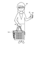
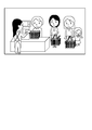
電子機器システム100は、図1に示すように、装着装置10と、カゴ装置20と、物品装置30と、サーバ40と、を備える。図2に示すように、装着装置10は、店舗に来店したユーザ(買い物客)が顔に装着する眼鏡型の端末である。カゴ装置20は、店舗に設置されたカゴ120に設けられる装置である。物品装置30は、店舗内に陳列された物品(商品)130に設けられる装置である。サーバ40は、店舗内やデータセンタなどに設けられる情報処理装置である。なお、装着装置10とカゴ装置20との間、及び物品装置30とカゴ装置20との間は、人体を介した通信(人体通信)が可能とされ、カゴ装置20とサーバ40との間は、無線通信が可能とされている。
(装着装置10)
装着装置10は、図1に示すように、撮像部11、表示部12、操作部13、マイク14、記憶部15、通信部16および制御部17を備える。なお、図3には、装着装置10が斜視図にて示されている。図3に示すように、装着装置10は、眼鏡型のフレーム110を備えている。なお、図1において図示され、図3において図示されていない装着装置10の構成は、フレーム110の内部や、フレーム110の一部に設けられているものとする。
装着装置10は、図1に示すように、撮像部11、表示部12、操作部13、マイク14、記憶部15、通信部16および制御部17を備える。なお、図3には、装着装置10が斜視図にて示されている。図3に示すように、装着装置10は、眼鏡型のフレーム110を備えている。なお、図1において図示され、図3において図示されていない装着装置10の構成は、フレーム110の内部や、フレーム110の一部に設けられているものとする。
撮像部11は、レンズ、撮像素子、画像処理部などを備え、静止画や動画を撮像するものである。撮像部11は、図3に示すようにフレーム110の端部近傍(ユーザの右目近傍)に設けられている。このため、ユーザが装着装置10を装着した状態(図2の状態)では、ユーザが向いている(見ている)方向の画像を撮像することができる。また、撮像された画像の所定部分(例えば、中心からやや左側にずれた部分)は、ユーザが視線を向けている部分(注視している部分)とみなすことができる。
表示部12は、フレーム110内部又はフレーム110近傍に設けられたプロジェクタと、プロジェクタからの投影像をユーザの目に導くためのプリズムとを有している。表示部12は、制御部17の指示の下、各種情報を表示する。
操作部13は、フレーム110に設けられたタッチパッドであり、ユーザの指の動きを検知して、ユーザからの操作を受け付け、受け付けた操作情報を制御部17に送信する。
なお、撮像部11、表示部12、操作部13については、例えば、米国公開特許2013/0044042号にもその詳細が開示されている。
マイク14は、フレーム110に設けられ、ユーザが発した音声やユーザの周辺の音声を収集する。マイク14が収集した音声は、不図示の音声認識部により音声認識され、音声認識結果は、制御部17に送信される。制御部17は、音声認識結果に基づく処理(例えば、コマンドの実行処理など)を実行する。なお、制御部17が音声認識を実行してもよい。また、制御部17は、収集した音声データを記憶部15に格納する。
記憶部15は、例えば、フラッシュメモリ等の不揮発性の半導体メモリであり、撮像部11が撮像した画像データや、マイク14が集音した音声データ、表示部12に表示する表示データなどを記憶する。
通信部16は、他の機器と人体通信を行うものである。通信部16は、フレーム110に設けられユーザと接触可能な電極部16aと、電極部16aを用いて人体通信を行う人体通信部16bと、を有する。なお、人体通信には、人体に微弱な電流を流して、その電流を変調して情報を伝達する電流方式や、人体の表面に誘起する電界を変調して情報を伝達する電界方式などがある。本実施形態では、電流方式及び電界方式のいずれのタイプを用いることも可能である。なお、ユーザが装着装置10の電極部16aに直接接触する場合はもちろん、電極部16aとユーザとが直接接触していない場合でも、人体通信は可能である。本実施形態において、通信部16は、撮像部11が撮像した画像データやマイク14が収集した音声データをカゴ装置20に送信するものである。なお、通信部16は、他の機器と例えばBluetooth(登録商標)、RFID(Radio Frequency Identification)、TransferJet(登録商標)などの近接通信を行ってもよい。
なお、通信部16に代えて、もしくは通信部16と併用して無線通信部を装着装置10に持たせてもよい。この場合、画像データや音声データを無線通信によりサーバ40に直接送信するようにしてもよいし、画像データや音声データを無線通信によりカゴ装置20に送信してもよい。
制御部17は、装着装置10全体を統括的に制御する。制御部17は、CPU(Central Processing Unit)、RAM(Random Access Memory)、ROM(Read Only Memory)等を備える。本実施形態では、制御部17は、撮像部11の撮像に関する制御や、表示部12の表示に関する制御などを行う。
なお、装着装置10は、眼鏡型の端末ではなくてもよい。例えば、体の任意の位置に装着可能な装着型端末であってもよく、その機能の一部が分離していてもよい。一例を挙げると、表示部を備えたコンタクトレンズ型の端末として、他の機能を腕時計型の端末に持たせるようにしてもよい。
(カゴ装置20)
カゴ装置20は、図1に示すように、生体センサ21、カレンダ部22、記憶部23、第1通信部24、第2通信部25、及び制御部26等を備える。
カゴ装置20は、図1に示すように、生体センサ21、カレンダ部22、記憶部23、第1通信部24、第2通信部25、及び制御部26等を備える。
生体センサ21は、カゴ120のうち、ユーザがカゴ120を持つ際に手が触れる部分(持ち手部分)に設けられる。生体センサ21は、心拍数、血圧、発汗量などの体の生体情報の変化を検出するものであって、例えば、LED(Light Emitting Diode)及びフォトセンサ、並びに、発汗センサを含む。例えば、LED及びフォトセンサを用いることで、LEDの照射する光を指に当てたときに反射する光をフォトセンサで受光することにより心拍数を検出することができる。また、発汗センサは、複数の電極により手のインピーダンスを測定することにより、発汗量を検出することができる。本実施形態においては、生体センサ21からの出力は、制御部26に送られる。そして、制御部26では、生体センサ21の出力に基づいてユーザの感情(喜怒哀楽)の変化を推定する。
カレンダ部22は、年、月、日、時刻といった時間情報を取得して、制御部26に対して出力する。また、カレンダ部22は計時を行う。
記憶部23は、例えば、フラッシュメモリ等の不揮発性の半導体メモリであり、後述するようにユーザが手にした物品に関する情報を記憶するものである。また、記憶部23は、カゴ装置20を一意に識別するためのID番号(カゴID)を記憶する。
第1通信部24は、他の機器と人体通信を行うものである。なお、第1通信部24は、他の機器と近接通信を行うこととしてもよい。本実施形態においては、第1通信部24は、人体通信を用いて装着装置10の通信部16及び物体装置30の通信部32と通信を行う。
第1通信部24は、カゴ120の持ち手部分に設けられた、ユーザの手や腕と接触可能な電極部24aと、電極部24aを介して人体通信を行う人体通信部24bと、を有する。
第2通信部25は、他の装置との間で無線通信を行うものである。本実施形態においてはサーバ40との間で無線通信を行い、ユーザが手に触れた物品の物品情報や、撮像部11が撮像した画像データ、マイク14が収集した音声データ、生体センサ21の検出結果をサーバ40に送信するものである。なお、本実施形態のカゴ装置20は、物品装置30とサーバ40との間における物品情報の通信、及び装着装置10とサーバ40との間における画像データや音声データの通信を中継する通信中継装置としての機能を有している。
制御部26は、カゴ装置20全体を制御するものであり、CPU、RAM、ROM等を備える。本実施形態では、制御部26は、物品装置30、装着装置10及びサーバ40との間における情報通信の制御を行う。
なお、カゴ装置20は、店舗で利用されるカートに設けることとしてもよい。この場合、生体センサ21や第1通信部24の電極部24aは、カートのグリップ部分に設けることが好ましい。
(物品装置30)
物品装置30は、店舗等で販売される物品(商品)であって、食料品、衣服、靴、時計、アクセサリー、ゴルフクラブ、バッグ等、来店者(ユーザ)の身体に接触する物品に設けられる。本実施形態では、説明の便宜上、物品装置30は、スーパーマーケットに陳列された商品(食料品等)に設けられているものとして説明する。
物品装置30は、店舗等で販売される物品(商品)であって、食料品、衣服、靴、時計、アクセサリー、ゴルフクラブ、バッグ等、来店者(ユーザ)の身体に接触する物品に設けられる。本実施形態では、説明の便宜上、物品装置30は、スーパーマーケットに陳列された商品(食料品等)に設けられているものとして説明する。
物品装置30は、図1に示すように、記憶部31と、通信部32と、制御部33と、を備える。
記憶部31は、例えば、フラッシュメモリ等の不揮発性の半導体メモリであり、物品装置30が取り付けられた物品(商品)に関する情報を記憶する。具体的には、記憶部31は、物品装置30が取り付けられた物品の物品情報(商品情報)を記憶する。例えば、物品装置30が加工食品(例えば缶詰)に取り付けられている場合には、記憶部31は、物品情報として、製造者(販売者)、商品名、原材料名、賞味期限、内容量、原産国等を記憶する。
制御部33は、物品装置30全体を制御するものであり、CPU、RAM、ROM等を備える。本実施形態では、制御部33は、記憶部31に記憶されている物品情報のカゴ装置20への送信を制御している。なお、制御部33及び記憶部31は物品のいずれの位置に設けられても構わない。
通信部32は、他の機器と人体通信を行うものである。なお、通信部32は、他の機器と近接通信を行うこととしてもよい。本実施形態において、通信部32は、ユーザ(例えば手)と接触する位置に設けられる電極部32aと、電極部32aを用いて人体通信を行う人体通信部32bと、を備える。本実施形態では、図2に示すように、カゴ120を持ったユーザが物品130を手にした状態で、カゴ装置20の第1通信部24と物品装置30の通信部32との間の人体通信が成立する。これにより、記憶部31に記憶された物品情報がカゴ装置20に送信される。なお、ユーザが物品装置30の電極部32aに直接接触する場合はもちろん、電極部32aとユーザとが直接接触していない場合(手袋をしている場合など)でも、人体通信は可能である。
(サーバ40)
サーバ40は、図1に示すように、記憶部41と、通信部42と、OCR(Optical Character Reader)部43と、画像認識部44と、制御部46と、を備える。
サーバ40は、図1に示すように、記憶部41と、通信部42と、OCR(Optical Character Reader)部43と、画像認識部44と、制御部46と、を備える。
記憶部41は、例えば、フラッシュメモリ等の不揮発性の半導体メモリや、ハードディスクドライブ等であり、カゴ装置20から取得した情報、すなわち、装着装置10の撮像部11が撮像した画像データやマイク14を用いて収集した音声データ、物品装置30から送信されてきた物品情報を記憶する。また、記憶部41は、店舗の従業員(店員)の顔画像データや商品画像データ、及びユーザの購入行動を分析する際に用いる各種データを記憶している。本実施形態においては、制御部46は、後述するように、画像認識部44と協働して装着装置10の撮像部11が撮像した画像データに従業員の顔や商品が含まれているかどうかを検出する。
通信部42は、他の機器と無線通信を行うものである。本実施形態では、通信部42は、無線通信によりカゴ装置20の第2通信部25と無線通信を行う。
OCR部43は、装着装置10の撮像部11が撮像した画像データに含まれる文字を認識して、テキストデータに変換する。例えば、撮像部11が、図7(b)の画像データを撮像した場合、OCR部43は、文字認識をして、テキストデータ「申し訳ございません。現在入荷待ちです。次回入荷時期は未定です。」を取得する。
画像認識部44は、装着装置10の撮像部11が撮像した画像データの特徴点を、例えばSURF(Speeded Up Robust Features)やSIFT(Scale Invariant Feature Transform)といった特徴量検出アルゴリズムにより抽出し、記憶部41に記憶されている複数の認識対象の標準パターンと比較することにより画像認識を行う。本実施形態においては、画像認識部44は、記憶部41に記憶されている従業員の顔画像データや商品画像データとの比較を行って、撮像部11が撮像した画像に従業員や商品が含まれているかどうかを検出する。
制御部46は、サーバ40全体を制御するものであり、CPU、RAM、ROM等を備える。
次に、図4(a)~図9を用いて、電子機器システム100の処理について、詳細に説明する。なお、本実施形態では、装着装置10を装着しているユーザ(買い物客)が店舗(例えば、スーパーマーケット)に来店した際に、カゴ120を保持して、買い物を行うものとする。また、ユーザは、店舗内で物品装置30が設けられた物品(商品)130を手に取ったり、カゴ120に入れたりすることで、購入する物品を決定し、レジで購入処理を行うものとする。
(装着装置10の処理)
図4(a)には、装着装置10の処理がフローチャートにて示されている。
図4(a)には、装着装置10の処理がフローチャートにて示されている。
図4(a)の処理では、装着装置10の制御部17は、ステップS10において、カゴ装置20との人体通信が成立するまで待機する。この場合、装着装置10を装着したユーザが店舗に入り、カゴ120を保持することでカゴ装置20にユーザの手が触れた段階で、装着装置10の通信部16とカゴ装置20の第1通信部24との間の通信が成立する。カゴ装置20との人体通信が成立すると、制御部17は、ステップS12に移行する。なお、ステップS10に代えて、ユーザが店舗に入店した後に装着装置10の電源をオンした段階でステップS12以降の処理を実行するようにしてもよい。この場合、装着装置10に、GPS(Global Positioning System)モジュールや、店舗内に設置された無線LAN(Local Area Network)基地局との通信状況に応じた位置検出が可能な位置検出装置を設け、位置検出装置の検出結果に基づいて、ユーザが店舗に入店したか否かを制御部17が判断することとしてもよい。また、これとは逆に、装着装置10は通信部16に常に電源を供給しておき、カゴ装置20との人体通信の成立により装着装置10が起動するようにしてもよい。
ステップS12に移行すると、制御部17は、撮像部11に指示を出し、ユーザ側からの撮像を実行する。この場合、撮像部11は、静止画及び動画のいずれを撮像してもよい。なお、本実施形態では、撮像部11は、静止画を撮像するものとして説明する。制御部17は、撮像部11によって撮像された画像(以下、視線画像と呼ぶ)を記憶部15に記憶する。なお、ステップS12では、撮像部11による視線画像の撮像に加えて、制御部17は、マイク14を用いて、ユーザの声や周辺の音を含む音声を収集し、音声データとして記憶部15に記憶してもよい。
次いで、ステップS14では、制御部17は、通信部16を介して、視線画像をカゴ装置20へ送信する。なお、制御部17は、例えば装着装置10に加速度計や角速度計を設けてユーザの移動速度を計測し、ユーザの移動速度が所定の移動速度(例えば時速1Km以下)になったときに、カゴ装置20へ視線画像を送信するようにしてもよい。なお、ユーザは、買い物途中にカゴ装置20から手を離す場合もある。したがって、制御部17は、人体通信が可能である場合には、人体通信により視線画像をカゴ装置20へ送信し、人体通信が不可能な場合には、近接通信や無線通信などにより視線画像をカゴ装置20へ送信するようにしてもよい。なお、無線通信を行う場合には、装着装置10が無線通信部を備えておく必要がある。
次いで、ステップS16では、制御部17は、レジ端末から入力のあったカゴ装置20との人体通信が成立したか否かを判断する。ここで、レジ端末からの入力とは、ユーザがレジにカゴ120を持っていった場合に、カゴ装置20とレジ端末との間の通信により、レジ端末からカゴ装置20に対して送信される、買い物終了情報の入力を意味する。すなわち、レジ端末からの入力があったカゴ装置20と装着装置10との人体通信が成立した場合、ユーザの買い物が終了したことを意味する。したがって、買い物が終了しておらず、ステップS16の判断が否定された場合には、ステップS12に戻り、ステップS12、S14、S16の処理・判断を繰り返す。すなわち、撮像部11による視線画像の撮像と、カゴ装置20への送信が繰り返される。一方、ユーザの買い物が終了し、ステップS16の判断が肯定された場合には、図4(a)の全処理が終了する。
なお、ステップS16に代えて、制御部17は、ユーザ(装着装置10)が店舗から出たか否かを判断してもよい。この場合、前述のように、装着装置10には、GPS等の位置検出装置を設けておく必要がある。
(物品装置30の処理)
図4(b)には、物品装置30の処理がフローチャートにて示されている。
図4(b)には、物品装置30の処理がフローチャートにて示されている。
図4(b)の処理では、物品装置30の制御部33は、ステップS20において、カゴ装置20との人体通信が新たに成立するまで待機する。この場合、図2に示すように、カゴ120を保持するユーザが物品130を商品棚等から取り上げたタイミングで、カゴ装置20との人体通信が新たに成立し、ステップS22に移行する。
ステップS22に移行すると、制御部33は、通信部32に指示を出し、記憶部31に記憶されている物品情報をカゴ装置20へ送信する。
その後は、ステップS20に戻り、制御部33は、ステップS20、S22の処理・判断を繰り返す。
図4(b)の処理が実行されることで、カゴ120を保持するユーザが、買い物途中に手にした物品130の情報をカゴ装置20に逐一送信することが可能となる。
(カゴ装置20の処理)
図5には、カゴ装置20の処理がフローチャートにて示されている。
図5には、カゴ装置20の処理がフローチャートにて示されている。
図5の処理では、ステップS30において、カゴ装置20の制御部26が、装着装置10との人体通信が成立するまで待機する。装着装置10との人体通信が成立すると、制御部26は、ステップS32に移行する。なお、ステップS32に移行するタイミングは、前述した図4(a)のステップS12に移行するタイミングと同一である。
ステップS32に移行すると、制御部26は、装着装置10から送信されてくる視線画像を取得し、記憶部23に記憶する。なお、例えばカゴ装置20に加速度計や角速度計を設けてユーザの移動速度を計測し、ユーザの移動速度が所定の移動速度(例えば時速1Km以下)になったときに、装着装置10から視線画像が送信されてきた画像を取得し、記憶部23に記憶することとしてもよい。
次いで、ステップS34では、制御部26が、新たな物品情報を受信したか否かを判断する。ステップS34の判断が否定された場合、すなわち、新たな物品情報を受信していない場合には、ステップS38に移行する。一方、ステップS34の判断が肯定された場合、すなわち、新たな物品情報を受信した場合には、ステップS36に移行する。
ステップS36に移行すると、制御部26は、物品情報を取得し、記憶部23に記憶する。その後は、ステップS38に移行する。
ステップS38に移行すると、制御部26は、生体センサ21を用いた検出を実行する。なお、ステップS32、S34及びS36、S38の処理の順番は適宜入れ替えてもよく、各ステップの処理を同時並行的に実行することとしてもよい。
次いで、ステップS40では、制御部26が、生体センサ21の検出結果に基づいて、ユーザに感情の変化があったか否かを判断する。この場合、例えば、生体センサ21の検出結果から、心拍数が急激に上昇した場合や、血圧が急激に上昇した場合、発汗量が急激に増加した場合などにおいて、ユーザに感情の変化があったと判断する。なお、ユーザの感情が変化する例としては、タイムサービスが始まり商品を安く購入できるチャンスに遭遇したり、購入を予定していた商品が売り切れであったり、レジが混雑しているような場合である。ステップS40の判断が否定された場合には、ステップS44に移行するが、ステップS40の判断が肯定された場合には、ステップS42に移行する。
ステップS42に移行すると、制御部26は、第2通信部25に指示を出し、記憶部23に記憶されている、感情変化直前に取得された視線画像及び物品情報(以下、第1情報と呼ぶ)をサーバ40に送信する。なお、感情変化直前とは、例えば、感情変化が生じる数秒前を意味する。なお、感情変化直前に物品情報が取得されない場合もある。感情変化が物品130を保持したことに起因しない場合である。この場合には、制御部26は、視線画像を第1情報としてサーバ40に送信すればよい。
ここで、感情変化直前に取得された視線画像としては、図7(a)、図7(b)、図8に示すような視線画像が想定される。図7(a)の視線画像は、ユーザがタイムサービスに遭遇したことを示す画像であり、具体的には、商品に貼付されたタイムサービスのシールをユーザが見たことを示す画像である。また、図7(b)の視線画像は、ユーザが購入しようとしていた商品が売り切れている場合の画像であり、具体的には、入荷待ちの掲示をユーザが見たことを示す画像である。また、図8の視線画像は、レジが混雑している状態をユーザが見たことを示す画像である。
なお、第1情報は、カゴIDが付加された状態でサーバ40に送信される。すなわち、サーバ40では、第1情報をカゴIDを用いて管理する。
ステップS40が否定された後、あるいはステップS42の処理が実行された後、制御部26は、ステップS44において、レジ端末から入力があったか否かを判断する。この場合のレジ端末の入力とは、前述したように、ユーザが買い物を終了し、レジにカゴ120を持っていった場合に、カゴ装置20とレジ端末との間の通信により、レジ端末からカゴ装置20に対して送信される、買い物終了情報の入力を意味する。このステップS44の判断が否定された場合、すなわち、ユーザの買い物が終了していない場合には、ステップS32に戻り、ステップS32~S44の処理・判断を繰り返す。一方、ステップS44の判断が肯定された場合には、ステップS46に移行する。
ステップS46に移行すると、制御部26は、第2通信部25に指示を出し、ステップS30以降取得された全ての視線画像、物品情報、生体情報(以下、第2情報と呼ぶ)をサーバ40に送信する。すなわち、制御部26は、第2通信部25を介して、ユーザが買い物をしている間に得られた視線画像、ユーザが手にした物品の物品情報、及びユーザが買い物をしている間に得られた感情の変化情報をサーバ40に送信する。なお、制御部26は、ユーザが買い物をしている間に装着装置10のマイク14を用いて取得された音声データをサーバ40に送信することとしてもよい。なお、制御部26から送信される各情報には、情報の取得時刻(カレンダ部22から得られる)がタイムスタンプとして付与されるものとする。また、第2情報は、カゴIDが付加された状態でサーバ40に送信される。すなわち、サーバ40では、第2情報をカゴIDを用いて管理する。その後は、制御部26は、図5の全処理を終了する。
以上のように、制御部26が図5の処理を実行することで、ユーザが買い物をしている間に感情の変化があったタイミングで、カゴ装置20からサーバ40に対して第1情報が送信され、ユーザが買い物を終了したタイミングで、カゴ装置20からサーバ40に対して第2情報が送信されるようになっている。
(サーバ40の処理)
図6には、サーバ40の処理がフローチャートにて示されている。
図6には、サーバ40の処理がフローチャートにて示されている。
図6の処理では、サーバ40の制御部46は、ステップS50において、カゴ装置20からの入力があるまで待機する。すなわち、制御部46は、カゴ装置20において図5のステップS42又はS46が実行されることにより、第1情報又は第2情報が送信されてきた段階で、ステップS52に移行する。
ステップS52に移行すると、制御部46は、入力された情報が第1情報であるか否かを判断する。すなわち、制御部46は、ユーザに感情の変化があった直前にカゴ装置20で取得された視線情報や物品情報が入力されたか否かを判断する。ここでの判断が肯定された場合には、ステップS54に移行する。
ステップS54に移行すると、制御部46は、第1情報に基づく感情分析を実行する。具体的には、制御部46は、感情が変化した直前に取得された視線画像をOCR部43や画像認識部44を用いて分析した結果や、感情が変化した直前に取得された物品情報を分析した結果に基づいて、ユーザの感情分析(満足か、不満かの分析)を行う。
例えば、制御部46は、視線画像が図7(a)の画像であった場合には、OCR部43を用いることで「朝市 タイムサービス 表示価格より20%引き」という文字を検出することができる。この場合、タイムサービス、20%引きといった、買い物客にとってポジティブな単語が含まれているため、制御部46は、ユーザが喜んで満足な状態(ポジティブな状態)であると分析する。なお、買い物客にとってポジティブな単語は、記憶部41に記憶されているものとする。
また、制御部46は、視線画像が図7(b)の画像であった場合には、OCR部43を用いることで、「申し訳ございません。現在入荷待ちです。次回入荷時期は未定です。」という文字を検出することができる。この場合、申し訳ございません、入荷待ち、未定といった、買い物客にとってネガティブな単語が含まれているため、制御部46は、ユーザが哀しんで不満足な状態(ネガティブな状態)であると分析する。なお、買い物客にとってネガティブな単語は、記憶部41に記憶されているものとする。
また、制御部46は、視線画像が図8の画像であった場合には、画像認識部44を用いることで、レジが混雑していることや、レジ待ちしている人が不満顔である(笑顔でない)ということを検出することができる。この場合、制御部46は、ユーザが哀しんで不満足な状態(ネガティブな状態)であると判断する。
また、制御部46は、視線画像に従業員の顔の画像が含まれる場合には、従業員に起因してユーザの感情が変化したと判断する。この場合、制御部46は、画像認識部44を用いることで、従業員の顔が笑顔か否かを認識する。なお、画像認識部44は、視線画像に含まれる顔の画像が従業員の顔の画像であるか否か、笑顔であるか否かを、記憶部41に記憶されている従業員の顔画像データを用いて判断する。そして、制御部46は、従業員が笑顔でない場合には、ユーザが哀しんでいる又は怒っている不満足な状態(ネガティブな状態)であると判断し、従業員が笑顔の場合には、満足な状態(ポジティブな状態)であると判断する。
更に、制御部46は、視線画像において物品を手に持っている状態が撮像されていた場合には、物品を見たこと、触れたことによって感情に変化が生じたと判断する。なお、制御部46は、例えば、カゴ装置20が取得した物品情報を併用することで、ユーザが喜んでいるのか哀しんでいるのかを判断することができる場合もある。例えば、物品情報に、数量限定などの情報が含まれている場合には、ユーザが喜んでいると判断することができる。また、物品情報から、賞味期限切れであることが判明した場合には、ユーザが哀しんでいると判断することができる。
図6に戻り、次のステップS56では、制御部46が、感情分析結果に基づいて、対応が必要か否かを判断する。具体的には、制御部46は、ユーザが哀しんでいたり怒っているなど不満足な状態の場合(ネガティブな状態にある場合)に、対応が必要であると判断する。ステップS56の判断が否定された場合には、ステップS50に戻る。一方、ステップS56の判断が肯定された場合には、ステップS58に移行する。
ステップS58に移行すると、制御部46は、感情分析結果に基づく対応処理を実行する。例えば、制御部46は、視線画像が図4(b)の場合には、記憶部41に記憶されているお詫びのメッセージや次回入荷予定などの各種メッセージを、通信部42を介して、カゴ装置20に送信する。そして、カゴ装置20の制御部26は、第1通信部24を介して、各種メッセージを装着装置10に送信する。この場合、装着装置10では、制御部17は、表示部12を用いて、各種メッセージを表示(投影)する。
また、例えば、視線画像が図8の場合には、制御部46は、レジが混雑していることに対するお詫びのメッセージを、カゴ装置20を介して装着装置10の制御部17に送信する。この場合、制御部17は、表示部12にお詫びのメッセージを表示(投影)する。なお、制御部46は、店内放送を利用して、レジの混雑に対するお詫びのメッセージを出力してもよい。また、制御部46は、店内放送を利用して、レジ打ちを行う従業員を補充すべき旨のメッセージ(レジ応援のメッセージ)を出力するようにしてもよい。あるいは、制御部46は、従業員が保持する端末に対して、レジ応援のメッセージを出力するようにしてもよい。また、制御部46は、レジが混雑している状況を見たユーザに対して、レジの進み具合(客1人当たりの処理時間)やレジを担当する店員の熟練度(見習いか、ベテランか)を報知することとしてもよい。
また、例えば、視線画像から、従業員の対応に問題があると判断された場合には、制御部46は、他の従業員や店長などが保持する端末に対して、客と従業員とのトラブルが発生した旨のメッセージを出力する。なお、カゴ装置20に無線LAN基地局との通信感度に応じて位置を検出することが可能な位置検出装置を設けておけば、制御部46は、位置検出装置の検出結果に基づいて、トラブル発生位置を他の従業員や店長などに知らせることができる。
更に、例えば、視線画像から、客が物品に対して哀しんでいる又は怒っていると判断された場合には、制御部46は、店内放送や従業員が保持する端末を利用して、従業員が直接対応すべき旨のメッセージを出力してもよい。この場合にも、制御部46は、従業員に客の位置を知らせるようにしてもよい。
なお、第1情報には、感情変化の直前にマイク14が収集した音声データが含まれていてもよい。制御部46は、音声データの分析により、音声データにユーザの怒声やため息、従業員の謝罪の言葉が含まれていた場合には、ユーザが怒っていたり、不満足な状態にある(ネガティブな状態にある)と判断することができる。
なお、上述した対応処理のパターンは、予め定められているものとし、当該パターンは、記憶部41に記憶されているものとする。
上記のようにしてステップS58の処理が終了した後は、ステップS50に戻る。
一方、ステップS52の判断が否定された場合、すなわち、カゴ装置20から入力された情報が第2情報であった場合には、ステップS60に移行する。
ステップS60に移行すると、制御部46は、第2情報に基づく、購入行動分析を実行する。この場合、制御部46は、ユーザが買い物の途中で、何を見て、何を手にとり、何を購入したかということを分析する。換言すれば、ユーザがどの商品を見なかったり、手に取らなかったかということを分析しているともいえる。
図9には、あるユーザが入店してからレジを通るまでの間に、手に取った物品の順が示されている。また、図9では、ユーザが購入した物品に下線を付している。なお、制御部46は、ユーザが購入した物品の情報として、レジ端末から取得した購入情報を利用することができる。
図9において、ユーザは、カレールーAとカレールーBとを手に取っているものの、最終的にはカレールーAを購入している。この場合、制御部46は、カレールーAを手に取った際の視線画像と、カレールーBを手に取った際の視線画像とを参照することで、何を判断基準として、カレールーAを購入したかを分析する。例えばユーザが注視している領域(視線画像の所定位置(ほぼ中心))に値段の情報が長時間含まれていた場合には、値段に基づいてカレールーAを購入したと判断する。また、ユーザが注視している領域に、辛さの表示や、パッケージの写真、成分表示や、賞味期限が長時間含まれていた場合には、それらの情報に基づいて、カレールーAを購入したと判断する。なお、制御部46は、ユーザが注視している領域に、値段や辛さの表示、成分や賞味期限などが含まれているか否かを、OCR部43を用いて抽出するものとする。
なお、牛肉A、Bについても同様に、購入の際の判断基準を判断するようにすればよい。例えば、制御部46は、ユーザが注視している領域に、内容量の表示や、部位の表示、100g当たりの値段などが長時間含まれていた場合には、それらの情報に基づいて、牛肉Bを購入したと判断する。
また、制御部46は、複数のユーザにおいて取得されたデータを参照することで、ある商品を購入したユーザが比較検討をした別の商品が何であるかを集計したり、比較検討した結果購入した商品の決め手が何であったかを集計したりすることができる。なお、購入の際の判断基準の分析結果は、各商品の製造元や生産者に提供することとしてもよい。製造元や生産者は、この分析結果を今後の商品開発や商品の改善に役立てることが可能である。
また、制御部46は、図9のデータを参照することで、客が物品を手に取った順番を集計することができる。この場合、制御部46は、集計結果を利用することで、客の店舗内における動きの傾向を分析することができる。これにより、制御部46は、客の動きに基づく、物品や棚の適切な配置を求めることができる。
更に、制御部46は、入店から退店までの間にユーザがポジティブな状態になった回数や位置、ネガティブな状態になった回数や位置を集計することで、客の満足度や不満足度を位置ごと(売り場ごと)に分析することができる。
また、制御部46は、客がネガティブな状態からポジティブな状態に変化した場合の視線画像を分析することとしてもよい。制御部46は、視線画像を分析した結果、ネガティブな状態からポジティブな状態に変化する間の視線画像に従業員の顔が含まれていた場合には、当該従業員の対応によりトラブルが解消したと分析することができる。また、ネガティブな状態からポジティブな状態に変化する間に装着装置10や店内放送を用いた対応処理を行っていた場合には、対応処理が適切であったと分析することができる。
以上、詳細に説明したように、本第1の実施形態によると、サーバ40の制御部46及び通信部42は、ユーザの購買に関する動作情報として視線画像や物品情報を入力し、ユーザの購買に関する生体情報として生体センサ21の検出結果を入力する。これにより、制御部46は、視線画像や物品情報、生体センサ21の検出結果に基づいた購買に関する分析を行い、購買に関する有用な情報を取得・提供することが可能となる。したがって、ユーザによる使い勝手を向上することができる。この場合、ユーザの側から撮像した視線画像を用いることで、店舗の棚側から撮像した画像を用いる場合と比較して、ユーザが実際に見ている状況、すなわち、視線の先にある物品や表示、状況等を考慮した分析が可能となる。
ここで、従来は、装着装置10のような撮像部11が搭載された装置を装着したユーザが店舗内に入店してきた場合、店舗内の様子や商品が勝手に撮像されてしまうため、店舗側にとってメリットがあるとはいえなかった。これに対し、本第1の実施形態では、ユーザが装着装置10を装着して店舗に入るのを許容する代わりに、店舗側は、撮像部11が撮像した画像データをカゴ装置20を介してもらうこととしている。これにより、店舗は、画像データを分析することで、ユーザの商品購入までの行動や感情を分析することが可能である。
また、従来は、ショッピングの満足度などをユーザに対するアンケートにより収集することとしていたが、ユーザにとっては店舗のWebサイトにアクセスして、質問に回答したり、紙に回答を筆記したりする必要があり煩わしいものであった。これに対し、本第1の実施形態では、装着装置10で取得された画像データとユーザの生体情報とを紐付けて店舗側に提供することにより、ユーザが無意識のうちに、ユーザの満足度や不満足度を店舗側に伝達することが可能である。
また、本第1の実施形態では、視線画像や物品情報、生体センサ21の検出結果に基づいて、ユーザへのメッセージや従業員へのメッセージを出力する。これにより、不満足に感じたユーザに対して即時対応を行うことが可能となる。
また、本第1の実施形態では、制御部46は、視線画像や物品情報からユーザが物品を保持したことを判断する。これにより、制御部46は、ユーザが物品を保持したという情報や保持した順番等を分析することで、購買に関する有用な情報を取得・提供することが可能となる。
また、本第1の実施形態では、制御部46は、生体センサ21の検出結果を利用するため、ユーザに感情の変化が生じたか否かを簡易に判断することが可能である。また、生体センサ21の検出結果とあわせてユーザの視線画像を分析することで、ユーザの感情がポジティブになったのか、ネガティブになったのかを精度よく判断することができる。
また、本第1の実施形態では、装着装置10が、視線画像を撮像し、撮像した視線画像を人体通信を介してユーザに接触しているカゴ装置20に対して送信する。これにより、カゴ装置20は、カゴ120を保持しているユーザの視線画像のみを取得することが可能である。すなわち、店舗に入店したユーザの装着装置10から視線画像を確実に取得し、店舗に入店していない人(例えば店舗付近を通りがかった人)の装着装置10から視線画像を取得してしまうのを確実に防止することができる。
また、本第1の実施形態では、生体センサ21の検出結果に変化があったとき、すなわち、ユーザの感情の変化があったときに、サーバ40に対して第1情報が送信される(S42)。これにより、分析が必要な情報を適切なタイミングでサーバ40に送信することができる。
なお、上記第1の実施形態では、生体センサ21をカゴ装置20が備える場合について説明したが、これに限らず、生体センサを装着装置10が備えていてもよい。この場合、装着装置10のフレームの一部やフレーム近傍に顔の一部と接触する生体センサを設けることとすればよい。また、装着装置10に耳たぶに装着可能な生体センサを接続するようにしてもよい。
また、上記第1の実施形態では、物品装置30を物品130に設ける場合について説明した。しかしながら、これに限られるものではなく、ステップS54の感情分析やステップS60の購入行動分析において物品情報が不要な場合には、物品装置30は必ずしも物品130に設けなくてもよい。例えば、視線画像において、物品を手に持っている状態が撮像されていた場合に、画像認識を行うことで、手に持っている物品を特定できる場合などである。
なお、上記第1の実施形態では、物品装置30がカゴ装置20との間で人体通信を行う場合について説明したが、これに限らず、物品装置30は、装着装置10との間で人体通信を行うこととしてもよい。この場合、装着装置10とカゴ装置20との間で人体通信が成立した状態で、装着装置10が取得した物品情報を装着装置10からカゴ装置20に対して送信するようにすればよい。
なお、上記第1の実施形態では、生体センサ21の検出結果を利用する場合について説明したが、これに限られるものではなく、生体センサ21の検出結果を利用しないこととしてもよい。この場合、制御部46は、例えば、視線画像に基づいて、ユーザが所定時間の間、図7(a)のマークを凝視していると判断した場合に、ユーザがポジティブな状態にあると推定することとしてもよい。また、制御部46は、例えば、視線画像に基づいて、ユーザが図7(b)の張り紙や図8のレジ待ち状態を所定時間凝視していると判断した場合に、ユーザがネガティブな状態にあると推定することとしてもよい。この場合、制御部46は、ユーザが見ることでポジティブ又はネガティブな状態になると予測されるマークや張り紙、状況の画像パターンを予め記憶しておき、該画像パターンと視線画像との比較を行うこととすればよい。
なお、上記第1の実施形態では、視線画像の所定位置を視線の中心位置とみなす場合について説明したが、これに限られるものではない。例えば、赤外線照射部と、赤外線受光部と、を有し、赤外線照射部から眼球に対して赤外線を照射し、眼球にて反射した赤外線を赤外線受光部において受光することで視線方向を検出する視線検出部を装着装置10に別途設けることとしてもよい。
なお、サーバ40は、複数の店舗における客の満足度や不満足度などを集計して、1つのWebサイトにおいて各店舗のユーザ評価として公表することとしてもよい。この場合、例えば、各店舗の評価を星の数や満足度の点数などで公表することができる。
《第2の実施形態》
次に、第2の実施形態に係る電子機器システム100’について、図10~図14(b)に基づいて、詳細に説明する。
次に、第2の実施形態に係る電子機器システム100’について、図10~図14(b)に基づいて、詳細に説明する。
図10には、電子機器システム100’の構成がブロック図にて示されている。図10では、電子機器システム100’のうち、第1の実施形態の電子機器システム100と異なる構成を太線枠にて示している。
図10に示すように、電子機器システム100’においては、装着装置10’がスピーカ18を備え、カゴ装置20’が重量センサ27を備え、物品装置30’が発光部34を備えている。なお、サーバ40’の構成は、第1の実施形態のサーバ40と同様である。
スピーカ18は、装着装置10’を装着するユーザに音声情報を提供するために用いられる。スピーカ18としては、イヤホンやヘッドホンのほか、指向性があり、装着装置10’を装着するユーザにのみ音声情報を提供することが可能なスピーカなどを採用することができる。なお、装着装置10’の記憶部15には、後述する物品装置30’の発光部34の発光パターンに対応する物品情報を格納しているものとする。
重量センサ27は、カゴ装置20’の一部に設けられ、カゴ120の内容量の変化を検出するためのセンサである。
発光部34は、LED(Light Emitting Diode)等の発光素子を含み、物品ごとに予め定められた発光パターンで、発光を行う。なお、発光部34の発光は、制御部33により制御される。装着装置10’の制御部17は、撮像部11による動画撮影において、画角の所定範囲内で発光パターンを撮像した場合に、ユーザがその発光パターンに対応する物品を見たと推定する。なお、発光部34による発光のオン・オフ切り替えタイミング(発光パターンの点滅間隔)は、撮像部11のフレームレートに合わせて設定されているものとする。なお、発光部34として可視光LEDを用いても赤外線LEDを用いてもよく、赤外線LEDを用いる場合には、撮像部11に赤外線撮像素子を用いればよい。
次に、本第2の実施形態における電子機器システム100’の処理について、図11(a)~図13のフローチャートに沿って、その他図面を適宜参照しつつ詳細に説明する。なお、本第2の実施形態においても、電子機器システム100’が、スーパーマーケットで利用される場合について説明する。
(装着装置10’の処理)
図11(a)には、装着装置10’の処理がフローチャートにて示されている。なお、図11(a)においては、第1の実施形態の装着装置10の処理(図4(a))と異なるステップを太線枠にて示している。
図11(a)には、装着装置10’の処理がフローチャートにて示されている。なお、図11(a)においては、第1の実施形態の装着装置10の処理(図4(a))と異なるステップを太線枠にて示している。
図11(a)の処理では、装着装置10’の制御部17は、ステップS10において、カゴ装置20’との人体通信が成立するまで待機する。カゴ装置20’との人体通信が成立すると、制御部17は、ステップS110に移行する。
ステップS110に移行すると、制御部17は、撮像部11に指示を出し、ユーザ側からの撮像(動画)を実行する。
次いで、ステップS112では、制御部17は、画角の所定範囲内において発光部34の発光を撮像したか否かを判断する。すなわち、ユーザが物品装置30’が設けられている物品を見たか否かを判断する。このステップS112における判断が否定された場合には、ステップS116に移行するが、ステップS112の判断が肯定された場合には、ステップS114に移行する。
ステップS114に移行すると、制御部17は、ユーザが見た物品情報をカゴ装置20’に送信する。具体的には、制御部17は、撮像部11の画角の所定範囲内において検出された発光パターンに対応する物品情報を記憶部15から取得し、通信部16を介してカゴ装置20’の第1通信部24に対して送信する。
ステップS112の判断が否定された後、あるいはステップS114の処理が行われた後、ステップS116に移行すると、制御部17は、カゴ装置20’から情報を受信したか否かを判断する。なお、カゴ装置20’から受信する情報とは、サーバ40’から送信されてくる物品や店舗のサービスに関する情報である。ここでの判断が否定された場合には、ステップS16に移行するが、肯定された場合には、ステップS118に移行する。
ステップS118に移行すると、制御部17は、カゴ装置20’から受信した情報を出力する。なお、本ステップS118の処理の詳細については、後述する。
ステップS116の判断が否定された後、あるいはステップS118の処理が行われた後、ステップS16に移行すると、制御部17は、レジ端末から入力のあったカゴ装置20’との人体通信が成立したか否かを判断する。ここで、レジ端末からの入力とは、ユーザが買い物を終了し、レジにカゴ120を持っていった場合に、カゴ装置20’とレジ端末との間の通信により、レジ端末からカゴ装置20’に対して送信される、買い物終了情報の入力を意味する。すなわち、レジ端末からの入力があったカゴ装置20’と装着装置10’との人体通信が成立した場合、ユーザの買い物が終了したことを意味する。したがって、買い物が終了しておらず、ステップS16の判断が否定された場合には、ステップS112に戻り、ステップS112~S16の処理・判断を繰り返す。一方、ユーザの買い物が終了し、ステップS16の判断が肯定された場合には、図11(a)の全処理が終了する。
(物品装置30’の処理)
図11(b)には、物品装置30’の処理がフローチャートにて示されている。なお、図11(b)においては、第1の実施形態の物品装置30の処理(図4(b))と異なるステップを太線枠にて示している。
図11(b)には、物品装置30’の処理がフローチャートにて示されている。なお、図11(b)においては、第1の実施形態の物品装置30の処理(図4(b))と異なるステップを太線枠にて示している。
図11(b)に示すように、物品装置30’では、ステップS120において、制御部33が、発光部34を用いた発光を行う。この場合、制御部33は、物品装置30’が設けられる物品に対応する発光パターンで、発光部34を発光させる。その他の処理は、図4(b)と同様である。
(カゴ装置20’の処理)
図12には、カゴ装置20’の処理がフローチャートにて示されている。図12の処理では、ステップS130において、制御部26は、装着装置10’との人体通信が成立するまで待機する。装着装置10’との人体通信が成立して、ステップS132に移行すると、制御部26は、装着装置10’から物品情報を受信したか否かを判断する。
図12には、カゴ装置20’の処理がフローチャートにて示されている。図12の処理では、ステップS130において、制御部26は、装着装置10’との人体通信が成立するまで待機する。装着装置10’との人体通信が成立して、ステップS132に移行すると、制御部26は、装着装置10’から物品情報を受信したか否かを判断する。
ステップS132の判断が肯定された場合には、ステップS134に移行し、制御部26は、装着装置10’から受信した物品情報を、見た物品の物品情報としてサーバ40’に送信し、ステップS136に移行する。一方、ステップS132の判断が否定された場合には、ステップS134を経ずにステップS136に移行する。
ステップS136に移行すると、制御部26は、物品装置30’から物品情報を受信したか否かを判断する。ステップS136の判断が肯定された場合には、ステップS138に移行し、制御部26は、物品装置30’から受信した物品情報を、触れた物品の物品情報としてサーバ40’に送信し、ステップS140に移行する。一方、ステップS136の判断が否定された場合には、ステップS138を経ずにステップS140に移行する。
ステップS140に移行すると、制御部26は、重量センサ27の検出値が変化したか否かを判断する。ここで、重量センサ27の検出値が変化した場合とは、物品がカゴ120内に新たに入れられたことを意味する。なお、カゴ120内の物品が取り出された場合も重量センサ27の検出値は変化するが、ここでは、説明の便宜上、カゴ120内から物品は取り出されないものとして説明する。ステップS140の判断が肯定された場合には、ステップS142に移行し、制御部26は、直前に触れていた物品の物品情報を、カゴに入れた物品の物品情報、すなわちユーザが購入予定の商品の情報としてサーバ40’に送信する。一方、ステップS140の判断が否定された場合には、ステップS142を経ずにステップS144に移行する。
ステップS144に移行すると、制御部26は、サーバ40’から情報を受信したか否かを判断する。なお、サーバ40’から受信する情報とは、物品や店舗のサービスに関する情報である。このステップS144の判断が肯定された場合には、ステップS146に移行し、制御部26は、サーバ40’から受信した情報を装着装置10’に送信し、ステップS148に移行する。一方、ステップS144の判断が否定された場合には、ステップS146を経ずに、ステップS148に移行する。
ステップS148に移行すると、制御部26は、レジ端末から入力があったか否かを判断する。ここで、レジ端末からの入力とは、前述したように、買い物終了情報の入力を意味する。
ステップS148の判断が否定された場合には、ステップS132に移行し、ステップS132~S148の処理・判断を繰り返すが、ステップS148の判断が肯定された場合には、制御部26は、図12の全処理を終了する。
(サーバ40’の処理)
図13には、サーバ40’の処理がフローチャートにて示されている。
図13には、サーバ40’の処理がフローチャートにて示されている。
図13の処理では、ステップS150において、制御部46は、カゴ装置20’から物品情報を受信するまで待機する。すなわち、ユーザが見た物品の物品情報、ユーザが触れた物品の物品情報、カゴ120に入れた物品の物品情報のいずれかが入力された段階で、制御部46は、ステップS152に移行する。
ステップS152に移行すると、制御部46は、記憶部41に格納されている買い物DBを更新する。ここで、買い物DBは、図14(a)に示すようなデータ構造を有している。図14(a)に示すように、物品名、見た、手に触れた、カゴに入れた、の各欄を有する。制御部46は、ユーザが見た物品の物品情報を受信した場合、当該物品の見たの欄に○を格納し、ユーザが触れた物品の物品情報を受信した場合、当該物品の触れたの欄に○を格納し、ユーザがカゴに入れた物品の物品情報を受信した場合、当該物品のカゴに入れたの欄に○を格納する。
次いで、ステップS154では、制御部46は、買い物DBを分析する。例えば、制御部46は、図14(a)の買い物DBを参照して、牛肉Aを手に持ってから所定時間経過したような場合(新たな物品情報を所定時間受信しないような場合)には、牛肉Aと比較対照となり得る物品(例えば、牛肉B)の情報をユーザが必要としている可能性があると分析することができる。また、制御部46は、例えば、カゴに入れた物品から、ユーザがカレーを作ることを推定できるため、カレーを作る際に必要な牛肉の量(4皿分ならXg、8皿分ならYgなど)の情報をユーザが必要としている可能性があると分析することができる。また、制御部46は、カレーの付け合せ(福神漬けやロースカツ、デザートなど)のお買い得情報や、店舗のキャンペーン情報(あとZ円買えば、クジが引けるなど)の情報をユーザが必要としている可能性があると分析することができる。
次いで、ステップS156では、制御部46は、ステップS154の分析の結果、ユーザに通知する情報が存在するか否かを判断する。ここでの判断が否定された場合には、ステップS150に戻るが、肯定された場合には、ステップS158に移行する。なお、同一の物品にユーザが複数回触れた場合や、以前触れた物品と類似する物品にユーザが触れた場合などにおいては、過去に通知した情報と同一の情報が、ユーザに通知する情報と判断される場合もある。したがって、制御部46は、過去に通知した情報と同一の情報については、ユーザに通知すべき情報ではないとして、通知を制限してもよい。すなわち、制御部46は、同一の物品に複数回触れた場合又は複数回見た場合、あるいは以前触れた又は見た物品と類似する物品に触れた又は見た場合に、通知される情報を制限することとしてもよい。このようにすることで、同一のユーザに同一の情報が繰り返し通知されるのを防止することができる。
なお、制御部46は、同じ物品に触れた回数や同じ物品を見た回数に応じて、通知すべき情報を変更することとしてもよい。例えば、制御部46は、1回目には物品そのものの情報、2回目にはその物品の比較対照となる物品の情報、3回目には物品に関連するお得情報、を通知すべき情報とすることとしてもよい。このようにすることで、物品の購入に迷っている客が当該物品を購入する可能性を向上することが可能となる。これに代えて、ユーザが同一の物品に触れた時間に応じて、2回目以降はユーザに通知していない情報からユーザに通知するようにしてもよい。
ステップS156の判断が肯定された場合、制御部46は、ステップS158に移行し、ユーザに通知する情報をカゴ装置20’に送信する。なお、ステップS158の処理が行われた場合、図12の処理では、ステップS144の判断が肯定され、ステップS146の処理(サーバから受信した情報を装着装置10’に送信する処理)が実行される。また、図12においてステップS146の処理が実行された場合、図11(a)のステップS116の判断が肯定され、ステップS118の処理(受信した情報を出力する処理)が実行される。ステップS118では、制御部17は、表示部12を用いて、ユーザに通知する情報を表示したり、スピーカ18を用いて、ユーザに通知する情報を出力したりする。なお、ステップS158の後は、ステップS150に戻り、ステップS150~S158の処理を繰り返す。
なお、制御部46は、買い物が終了したユーザの買い物DB(例えば、図14(b))に基づいて、各種分析を行うこととしてもよい。この場合、制御部46は、例えば、図14(b)に基づいて、カレールーAとカレールーB、及び牛肉Aと牛肉Bが比較され、カレールーB、牛肉Bが購入されたことを分析することができる。また、制御部46は、店内を歩く順番、購入の順番などを分析することもできる。また、制御部46は、商品を見ただけで購入しなかった物品、手に取ったけど購入しなかった物品を特定し、分析することができる。制御部46は、分析結果を商品の製造元、販売元等に提供することとしてもよい。
以上、詳細に説明したように、本第2の実施形態によると、制御部46は、物品をユーザが手にしたこと、及び物品がユーザの視野内の所定範囲に入ったことの少なくとも一方に応じて、物品の物品情報を入力し(S150:肯定)、入力した物品情報に関する通知を行う(S158)。したがって、本第2の実施形態では、ユーザが手に触れた物品やユーザが見た物品に関連した有用な情報を、ユーザに対して報知することができる。これにより、ユーザの使い勝手を向上することができる。
また、本第2の実施形態では、制御部46は、物品情報としてカゴ120内に入れられたユーザが購入予定の商品の情報を入力し、入力した商品に応じた通知を行う。これにより、ユーザが購入予定の商品に関連した有用な情報を、ユーザに対して報知することができる。また、制御部46は、買い物時に使用されるカゴ装置20’から購入予定の商品の情報を入力するので、購入予定の商品の情報として正確な情報を入力することができる。
また、本第2の実施形態では、ユーザへの情報の通知を装着装置10’の表示部12や指向性のあるスピーカ18から行うので、他のユーザに知られることなく、ユーザごとにユーザの購買行動に応じた通知を行うことができる。
なお、上記第2の実施形態では、制御部46は、ユーザがある物品を手に持ちながら、別の物品を見ている場合に、両商品を比較検討していると判断してもよい。
なお、上記第2の実施形態では、スーパーマーケットにおいて電子機器システム100’を利用する例について説明したが、これに限らず、衣料品店等において電子機器システム100’を利用することとしてもよい。例えば、制御部46は、ユーザが服を手に取ったときに、色違い、サイズ違いなどの在庫の有無の情報、類似商品でセール中の商品があるか否かの情報、あと1着買うと値引き、あと2000円以上買うと値引きなどの値引き情報等を表示部12やスピーカ18を用いて報知することにより、他のユーザに知られることなく、特定のユーザ(店舗の会員などのお得意様)だけに通知することができる。また、サーバ40’は、店舗の会員のユーザが誕生日に来店した際に、装着装置10’に値引き情報、プレゼント情報、お祝いのメッセージを送信するようにしてもよい。
なお、上記第2の実施形態では、制御部17は、装着装置10’において取得された物品情報をカゴ装置20’を経由してサーバ40’に送信する場合について説明したが、これに限られるものではない。例えば、装着装置10’が無線通信可能な通信部を有している場合には、無線通信により、装着装置10’からサーバ40’に情報を送信するようにしてもよい。
なお、上記第2の実施形態では、物品装置30’が発光部34を有する場合について説明したが、これに限らず、物品装置30’は発光部34を有していなくてもよい。この場合、制御部17は、撮像部11が撮像した画像を解析することで、ユーザが見た物品を特定するようにすればよい。例えば、制御部17は、表示に含まれる文字(例えば商品タグやPOP広告の文字)を認識して、ユーザが見た物品を特定することとしてもよい。
なお、上記第2の実施形態では、サーバ40’が、図13の処理を実行する場合について説明したが、これに限られるものではない。例えば、サーバ40’の処理を装着装置10’やカゴ装置20’が実行することとしてもよい。
なお、上記第1、第2の実施形態においては、制御部46は、情報を分析する際に、ユーザの種別を考慮することとしてもよい。ユーザの種別は店舗の会員であれば、登録されている情報(名前、生年月日、住所、買物履歴)から把握できる。この場合、ユーザの性別や年代ごとに、ユーザの購買行動を分析することとしてもよい。
上述した各実施形態は本発明の好適な実施の例であり、適宜組み合わせることができる。但し、これに限定されるものではなく、本発明の要旨を逸脱しない範囲内において種々変形実施可能である。なお、これまでの説明で引用した米国特許出願公開明細書の開示を援用して本明細書の一部とする。
Claims (27)
- ユーザの購買に関する動作情報を入力する第1入力部と、
前記ユーザの購買に関する生体情報を入力する第2入力部と、を備えたことを特徴とする電子機器。 - 前記第1入力部と前記第2入力部とが入力した情報に基づいて、前記ユーザの満足度または不満足度を検出する検出部を備えたことを特徴とする請求項1記載の電子機器。
- 前記第1入力部と前記第2入力部とが入力した情報に基づいて、前記ユーザへの対応を指示する指示部を備えたことを特徴とする請求項1または2記載の電子機器。
- 前記第1入力部は、前記ユーザの手の動きに関する情報を入力することを特徴とする請求項1から3のいずれか一項に記載の電子機器。
- 前記第2入力部は、前記ユーザの購買に関する感情情報の推定に用いる前記ユーザの生体情報を入力することを特徴とする請求項1から4のいずれか一項に記載の電子機器。
- 前記第1入力部及び前記第2入力部の少なくとも一方は、前記ユーザ側からの目に関する情報を入力することを特徴とする請求項1から5のいずれか一項に記載の電子機器。
- 前記ユーザ側からの目に関する情報を取得する取得装置と通信可能な通信部を備えたことを特徴とする請求項6記載の電子機器。
- 前記通信部は、前記取得装置に設けられた通信部と通信することを特徴とする請求項7記載の電子機器。
- 前記通信部は、前記取得装置とは異なる通信中継装置を介して前記取得装置と通信することを特徴とする請求項7記載の電子機器。
- 前記通信部は、前記通信中継装置との近接通信または人体通信を介して前記取得装置と通信することを特徴とする請求項9記載の電子機器。
- 前記取得装置は、撮像を行う撮像部を有し、
前記撮像部が撮像した撮像データを分析する分析部を備えたことを特徴とする請求項7から10のいずれか一項に記載の電子機器。 - 前記第2入力部が入力する前記生体情報の変化に応じて、前記第1入力部が前記動作情報を入力することを特徴とする請求項1から11のいずれか一項に記載の電子機器。
- ユーザ側からの目に関する情報を入力する入力部と、
前記ユーザ側からの目に関する情報に基づいて前記ユーザの購買に関する感情情報を推定する推定部と、を備えたことを特徴とする電子機器。 - 前記推定部は、前記ユーザ側からの目に関する情報が予め定められたパターンと一致又は類似するか否かに基づいて、前記ユーザの購買に関する感情情報を推定することを特徴とする請求項13に記載の電子機器。
- 前記ユーザの移動速度を取得する速度取得部を備え、
前記推定部は、前記ユーザの移動速度に応じて、前記入力部に入力される情報を取得し、取得した前記情報に基づいて前記推定を行うことを特徴とする請求項13または14に記載の電子機器。 - ユーザの顔付近に装着可能な電子機器であって、
前記ユーザ側からの目に関する情報を取得する取得部と、
前記取得部が取得した情報を、人体通信を介して前記ユーザに接触している外部機器との間で通信する通信部と、を備えたことを特徴とする電子機器。 - 前記ユーザの移動速度を取得する速度取得部を備え、
前記通信部は、前記ユーザの移動速度に応じて、前記取得部が取得した情報を、前記外部機器に送信することを特徴とする請求項16に記載の電子機器。 - 物品をユーザが手にしたこと、及び物品がユーザの視野内の所定範囲に入ったことの少なくとも一方に応じて、前記物品の情報を入力する入力部と、
前記入力部が入力した前記物品の情報に関する報知を行う報知部と、を備えた電子機器。 - 前記ユーザが前記物品を複数回手にしたとき、又は前記ユーザの視野内の所定範囲に前記物品が複数回入ったときに、前記報知部が報知する情報を制限する第1制御部を備えたことを特徴とする請求項18記載の電子機器。
- 前記第1制御部は、前記物品を手にした回数、又は前記物品が前記ユーザの視野内の所定範囲内に入った回数に応じて、前記報知部が報知する情報を異ならせることを特徴とする請求項19に記載の電子機器。
- 前記物品と類似する類似物品を前記ユーザが手にしたとき、又は前記ユーザの視野内の所定範囲に前記類似物品が入ったときに、前記報知部が報知する情報を制限する第2制御部を備えたことを特徴とする請求項18から20のいずれか一項に記載の電子機器。
- 前記入力部は、前記物品の情報として前記ユーザが購入予定の商品の情報を入力し、
前記報知部は、前記購入予定の商品に応じた情報を報知することを特徴とする請求項18から21のいずれか一項に記載の電子機器。 - 前記入力部は、外部機器から前記購入予定の商品の情報を入力することを特徴とする請求項22記載の電子機器。
- 前記入力部は、前記購入予定の商品を収納する収納装置を介して、前記外部機器から前記購入予定の商品に応じた情報を入力することを特徴とする請求項23記載の電子機器。
- 前記報知部は、表示を行う表示部と、音声を出力する音声出力部との少なくとも一方を備えていることを特徴とする請求項18から24のいずれか一項に記載の電子機器。
- 前記音声出力部は、指向性のある音声出力部であることを特徴とする請求項25記載の電子機器。
- 前記ユーザの顔付近に装着可能な装着部を備えたことを特徴とする請求項18から26のいずれか一項に記載の電子機器。
Applications Claiming Priority (4)
| Application Number | Priority Date | Filing Date | Title |
|---|---|---|---|
| JP2013-253402 | 2013-12-06 | ||
| JP2013253402A JP2015111357A (ja) | 2013-12-06 | 2013-12-06 | 電子機器 |
| JP2013-253403 | 2013-12-06 | ||
| JP2013253403A JP2015111358A (ja) | 2013-12-06 | 2013-12-06 | 電子機器 |
Publications (1)
| Publication Number | Publication Date |
|---|---|
| WO2015083495A1 true WO2015083495A1 (ja) | 2015-06-11 |
Family
ID=53273266
Family Applications (1)
| Application Number | Title | Priority Date | Filing Date |
|---|---|---|---|
| PCT/JP2014/079678 Ceased WO2015083495A1 (ja) | 2013-12-06 | 2014-11-10 | 電子機器 |
Country Status (1)
| Country | Link |
|---|---|
| WO (1) | WO2015083495A1 (ja) |
Cited By (1)
| Publication number | Priority date | Publication date | Assignee | Title |
|---|---|---|---|---|
| CN107924522A (zh) * | 2015-06-24 | 2018-04-17 | 奇跃公司 | 用于购买的增强现实设备、系统和方法 |
Citations (6)
| Publication number | Priority date | Publication date | Assignee | Title |
|---|---|---|---|---|
| JP2007058534A (ja) * | 2005-08-24 | 2007-03-08 | Fujitsu Business Systems Ltd | 顧客嗜好情報収集装置および顧客嗜好情報収集方法 |
| JP2007328464A (ja) * | 2006-06-06 | 2007-12-20 | Sharp Corp | 購買活動管理装置、制御方法、制御プログラムおよびそれを記録したコンピュータ読み取り可能な記録媒体 |
| JP2009003701A (ja) * | 2007-06-21 | 2009-01-08 | Denso Corp | 情報システム及び情報処理装置 |
| JP2010072828A (ja) * | 2008-09-17 | 2010-04-02 | Olympus Corp | 情報提示システム、情報処理システム、プログラム及び情報記憶媒体 |
| JP2011065504A (ja) * | 2009-09-18 | 2011-03-31 | Tokyo Univ Of Science | ユーザの選好関係についての予測モデルを生成する選好予測サーバ及びその方法 |
| WO2014013649A1 (ja) * | 2012-07-19 | 2014-01-23 | 株式会社ニコン | 電子機器および方法 |
-
2014
- 2014-11-10 WO PCT/JP2014/079678 patent/WO2015083495A1/ja not_active Ceased
Patent Citations (6)
| Publication number | Priority date | Publication date | Assignee | Title |
|---|---|---|---|---|
| JP2007058534A (ja) * | 2005-08-24 | 2007-03-08 | Fujitsu Business Systems Ltd | 顧客嗜好情報収集装置および顧客嗜好情報収集方法 |
| JP2007328464A (ja) * | 2006-06-06 | 2007-12-20 | Sharp Corp | 購買活動管理装置、制御方法、制御プログラムおよびそれを記録したコンピュータ読み取り可能な記録媒体 |
| JP2009003701A (ja) * | 2007-06-21 | 2009-01-08 | Denso Corp | 情報システム及び情報処理装置 |
| JP2010072828A (ja) * | 2008-09-17 | 2010-04-02 | Olympus Corp | 情報提示システム、情報処理システム、プログラム及び情報記憶媒体 |
| JP2011065504A (ja) * | 2009-09-18 | 2011-03-31 | Tokyo Univ Of Science | ユーザの選好関係についての予測モデルを生成する選好予測サーバ及びその方法 |
| WO2014013649A1 (ja) * | 2012-07-19 | 2014-01-23 | 株式会社ニコン | 電子機器および方法 |
Cited By (2)
| Publication number | Priority date | Publication date | Assignee | Title |
|---|---|---|---|---|
| CN107924522A (zh) * | 2015-06-24 | 2018-04-17 | 奇跃公司 | 用于购买的增强现实设备、系统和方法 |
| CN107924522B (zh) * | 2015-06-24 | 2022-06-03 | 奇跃公司 | 用于购买的增强现实设备、系统和方法 |
Similar Documents
| Publication | Publication Date | Title |
|---|---|---|
| US12277586B2 (en) | Augmented reality systems and methods for purchasing | |
| US11074610B2 (en) | Sales promotion system, sales promotion method, non-transitory computer readable medium, and shelf system | |
| US20190174284A1 (en) | Physiologic Sensors for Sensing, Measuring, Transmitting, and Processing Signals | |
| JP6800820B2 (ja) | 人流分析方法、人流分析装置、及び人流分析システム | |
| US20160203499A1 (en) | Customer behavior analysis system, customer behavior analysis method, non-transitory computer readable medium, and shelf system | |
| JP2018005691A (ja) | 情報処理システム、情報処理装置及び情報処理方法 | |
| JP7490988B2 (ja) | クーポン発行装置、方法、及び、プログラム | |
| JP7424459B2 (ja) | 販売促進装置、販売促進方法およびプログラム | |
| CN104254861A (zh) | 用于辅助定位存储位置中的物品的方法 | |
| US20210192592A1 (en) | Indoor Localization Enabled Shopping Assistance in Retail Stores | |
| JP2015111358A (ja) | 電子機器 | |
| JP2025023230A (ja) | 電子機器システム | |
| US20240320701A1 (en) | Wearable device, information processing method, non-transitory computer readable recording medium storing information processing program, and information providing system | |
| WO2015083495A1 (ja) | 電子機器 | |
| JP2015111357A (ja) | 電子機器 | |
| JP6504279B2 (ja) | 電子機器システム | |
| JP6508367B2 (ja) | 電子機器システム及び報知方法 | |
| JP2019114293A (ja) | 電子機器 | |
| JPWO2023112519A5 (ja) | ||
| JP2026014507A (ja) | 販売データ処理装置及び情報処理プログラム | |
| US20230005031A1 (en) | System and method for accessing data via smart articles including purchasing data |
Legal Events
| Date | Code | Title | Description |
|---|---|---|---|
| 121 | Ep: the epo has been informed by wipo that ep was designated in this application |
Ref document number: 14866916 Country of ref document: EP Kind code of ref document: A1 |
|
| NENP | Non-entry into the national phase |
Ref country code: DE |
|
| 122 | Ep: pct application non-entry in european phase |
Ref document number: 14866916 Country of ref document: EP Kind code of ref document: A1 |