WO2015080299A1 - Angle detection device, angle detection method, motor driving device, and image forming apparatus - Google Patents
Angle detection device, angle detection method, motor driving device, and image forming apparatus Download PDFInfo
- Publication number
- WO2015080299A1 WO2015080299A1 PCT/JP2014/082186 JP2014082186W WO2015080299A1 WO 2015080299 A1 WO2015080299 A1 WO 2015080299A1 JP 2014082186 W JP2014082186 W JP 2014082186W WO 2015080299 A1 WO2015080299 A1 WO 2015080299A1
- Authority
- WO
- WIPO (PCT)
- Prior art keywords
- rotor
- phase
- angle
- rotation angle
- angle detection
- Prior art date
- Legal status (The legal status is an assumption and is not a legal conclusion. Google has not performed a legal analysis and makes no representation as to the accuracy of the status listed.)
- Ceased
Links
Classifications
-
- G—PHYSICS
- G01—MEASURING; TESTING
- G01D—MEASURING NOT SPECIALLY ADAPTED FOR A SPECIFIC VARIABLE; ARRANGEMENTS FOR MEASURING TWO OR MORE VARIABLES NOT COVERED IN A SINGLE OTHER SUBCLASS; TARIFF METERING APPARATUS; MEASURING OR TESTING NOT OTHERWISE PROVIDED FOR
- G01D5/00—Mechanical means for transferring the output of a sensing member; Means for converting the output of a sensing member to another variable where the form or nature of the sensing member does not constrain the means for converting; Transducers not specially adapted for a specific variable
- G01D5/12—Mechanical means for transferring the output of a sensing member; Means for converting the output of a sensing member to another variable where the form or nature of the sensing member does not constrain the means for converting; Transducers not specially adapted for a specific variable using electric or magnetic means
- G01D5/244—Mechanical means for transferring the output of a sensing member; Means for converting the output of a sensing member to another variable where the form or nature of the sensing member does not constrain the means for converting; Transducers not specially adapted for a specific variable using electric or magnetic means influencing characteristics of pulses or pulse trains; generating pulses or pulse trains
- G01D5/24471—Error correction
- G01D5/24476—Signal processing
Definitions
- the present invention relates to an angle detection device, an angle detection method, a motor driving device, and an image forming apparatus.
- a rotation angle of a rotor of a motor arises when, for example, controlling a rotational position of the motor.
- a rotation angle of a rotor of a motor can generally be detected using a rotary encoder connected to a rotary shaft of the motor's rotor. With this method, two-phase pulse signals having a quarter- period phase difference and varying with the rotation angle of the motor's rotor can be obtained from the rotary encoder.
- a relative rotation angle of the motor's rotor is detectable based on a result of edge detection of the two- phase pulse signals and High/Low states of the two-phase pulse signals.
- An optical encoder is generally used as the rotary encoder.
- the optical encoder typically includes a disk and two photo interrupters. Slits serving as optical windows are provided in an outer peripheral portion of the disk at a regular slit pitch.
- the two photo interrupters are arranged at a pitch corresponding to a quarter of the slit pitch of the disk.
- the two-phase pulse signals can be obtained by binarizing output signals of the two photo interrupters .
- optical encoder requires components of the slit-provided disk and the photo interrupters and, furthermore, requires that the components be mounted, which can result in an increase in cost.
- Patent No. 4111813 two magnetic sensors, each outputting a signal which varies sinusoidally with a rotation angle of a rotor of a motor, are arranged so as to have a 90-degree phase difference.
- the rotation angle of the motor's rotor is denoted by ⁇
- an X-phase signal and a Y-phase signal of two-phase signals output from the magnetic sensors are denoted by Vx and Vy, respectively.
- Vx can be expressed by a cosine function of the rotation angle ⁇ having amplitude Ax
- Vy can be expressed by a sine function of the rotation angle ⁇ having amplitude Ay.
- the cosine function and the sine function are shown in FIG.
- Equations (2) which represent an angle search algorithm, a predetermined step angle Gstep in the negative rotating direction as illustrated in FIG. 21 until a Y component Vy' (n) of the thus-rotated vector changes from a positive value to a negative value.
- rotation angle ⁇ of the vector obtained in this manner is the detected rotation angle of the motor's rotor.
- the rotation angle of the motor's rotor can be detected by periodically performing the operation described above.
- a brushless motor is configured to include multiple Hall elements arranged with a
- Hall elements for commutation in a most-typical three-phase brushless motor are arranged so as to output signals with a mutual phase difference of 120°.
- a Hall element which output a signal having a 90-degree phase difference Accordingly, a general-purpose motor unit made by assembling coils, a rotor, and Hall elements with the 120-degree phase difference together in one piece cannot be used. This also leads to an increase in cost.
- a vector generating unit synthesizes sinusoidal signals having a 90-degree phase difference by performing operation given by Equations (3) on sinusoidal signals output from three Hall elements provided in a brushless motor with a phase difference of other than 90°. By performing the operation, a rotation angle of a rotor is detected without addition of a sensor.
- An angle detection device includes: an angle detection unit that detects a rotation angle of a rotor based on output signals of multiple magnetic sensors arranged so as to detect the rotation angle of the rotor of a motor and have a phase difference from each other, and an amplitude- fluctuation removing unit that removes an amplitude
- FIG. 1 is a schematic configuration diagram of a motor unit including Hall elements.
- FIG. 2 is a diagram illustrating differential signals output from the Hall elements.
- FIG. 3 is a configuration diagram of an angle
- FIGS. 4A and 4B illustrate a waveform of a Hall- element output signal onto which a third harmonic is superimposed.
- FIGS. 5A and 5B illustrate a waveform of Hall-element output signal onto which an amplitude fluctuation component having a period corresponding to one turn of a rotor is superimposed.
- FIG. 6 is a diagram illustrating transformation from UVW axes to XY axes.
- FIGS. 7A and 7B are diagrams illustrating logic for generating two-phase pulse signals.
- FIG. 8 is a configuration diagram of a calculation circuit executing operation of the angle detection device illustrated in FIG. 3.
- FIG. 9 is an explanatory diagram illustrating
- FIG. 10 is a table illustrating control timing for the calculation circuit illustrated in FIG. 8.
- FIG. 11 is a configuration diagram of the angle generator illustrated in FIG. 3.
- FIG. 12 is a configuration diagram of the sine-data generation unit illustrated in FIG. 11.
- FIG. 13 is an overall configuration diagram of a motor driving device according to a second embodiment of the present invention.
- FIG. 14 is a diagram illustrating conditions for generating a Hall signal.
- FIG. 15 is a configuration diagram of an upper arm of the driving commutation circuit illustrated in FIG. 13.
- FIG. 16 is a diagram illustrating operations of the modulation unit illustrated in FIG. 13.
- FIG. 17 is a diagram illustrating the Hall signals and phase logic of rectangular pulse driving.
- FIG. 18 is a diagram illustrating relationship between phase logic and gate signals.
- FIG. 19 is a cross-sectional view illustrating an example of an image forming apparatus according to a third embodiment of the present invention.
- FIG. 20 is a diagram illustrating waveforms of two- phase sinewave signals having a 90-degree phase difference.
- FIG. 21 is a diagram illustrating an example operation of an angle search algorithm according to a conventional technique.
- FIG. 1 is a schematic configuration diagram of a motor unit including Hall elements.
- FIG. 2 is a diagram illustrating
- FIG. 3 is a configuration diagram of an angle detection device according to the first embodiment of the present invention'.
- FIGS. 4A and 4B illustrate a waveform of a Hall-element output signal onto which a third harmonic is superimposed.
- FIGS. 5A and 5B illustrates a waveform of a Hall-element output signal onto which an amplitude fluctuation component having a period corresponding to one turn of a rotor is superimposed.
- FIG. 6 is a diagram illustrating
- FIGS. 7A and 7B are diagrams illustrating logic for generating two-phase pulse signals.
- FIG. 8 is a configuration diagram of a calculation circuit executing operation of the angle detection device illustrated in FIG. 3.
- FIG. 9 is an explanatory diagram illustrating relationship between a clock signal and a count value.
- FIG. 10 is a table
- FIG. 11 is a configuration diagram of the angle generator illustrated in FIG. 3.
- FIG. 12 is a configuration diagram of the sine-data generation unit illustrated in FIG. 11.
- a brushless motor 10 As illustrated in FIG. 1, a brushless motor 10
- the brushless motor 10 includes Y-connected three-phase coils 13U, 13V, 13W (not shown in FIG. 1; see FIG. 13), which are composed of three phase of a U-phase, a V-phase, and a W-phase, having a mutual phase difference of 120°.
- the brushless motor 10 further includes a rotor 11 positioned to face the coils 13U, 13V, and 13W and including a permanent magnet
- the permanent magnet of the rotor 11 contains 12 poles (the number of pole pairs is 6) .
- three Hall elements 15U, 15V, and 15 serving as multiple magnetic sensors are fixedly arranged near the rotor 11 to detect a rotational angular position of the rotor 11.
- the Hall elements 15U, 15V, and 15W output differential signals HU+/HU- of the U-phase, HV+/HV- of the V-phase, and HW+/HW- of the W-phase,
- Analog Hall signals Hu, Hv, and Hw are obtained by single-ending the differential signals HU+/HU-, HV+/HV-, and HW+/HW-. "Single-ending” denotes converting a differential signal into a single-ended signal.
- FIG. 2 illustrates the analog Hall signals Hu, Hv, and Hw sinusoidally vary as the rotor 11 rotates.
- the Hall elements 15U, 15V, and 15W are arranged so that waveforms of the analog Hall signals Hu, Hv, and Hw have a mutual phase difference of 120°.
- FIG. 2 illustrates the three phase signals on the assumption that they are equal in amplitude.
- the number of the magnetic poles of the rotor 11 according to the present embodiment is 12.
- each of the sinewaves illustrated in FIG. 2 repeats six cycles in one turn of the rotor 11.
- a one-sixth turn of the rotor 11 corresponds to one cycle of each of the sinewaves illustrated in FIG. 2.
- a rotation angle ( ⁇ ) of the rotor 11 of the brushless motor 10 is given in degrees where 360 is one cycle of the sinewave of each of the analog Hall signals Hu, Hv, and Hw.
- an actual rotation angle (mechanical angle) of the rotor 11 of the brushless motor 10 is one sixth of the value ( ⁇ : electrical angle) given in degrees where 360 is one cycle of the sinewaves of the analog Hall signals Hu, Hv, and Hw in this manner.
- the actual rotation angle of the rotor 11 of the brushless motor 10 is a one-sixth of 360°, or 60°.
- the Hall elements 15U, 15V, and 15W correspond to the multiple sensors that output the sinusoidal signals which vary with the rotation angle of the rotor and differ from each other in phase due to positions of the Hall elements 15U, 15V, and 15W.
- the angle detection device 20 broadly includes a differential amplifier 22, an analog-to-digital (A/D) converter 23, a harmonic removing unit 24, an
- amplitude-fluctuation removing unit 25 a vector generation unit 30, a vector rotation unit 40, an angle generator 50, and a two-phase-pulse generation unit 65.
- the differential amplifier 22 Upon receiving differential signals from the Hall elements 15U, 15V, and 15W of the brushless motor 10, the differential amplifier 22 converts the U-phase differential signal HU+/HU- and the V-phase differential signal HV+/HV- into the single-ended, analog Hall signals Hu and Hv, respectively, and outputs the analog Hall signals.
- waveforms of the analog Hall signals Hu and Hv are expressed by Equations (4) which represent waveforms of differential outputs of the three-phase Hall elements.
- the waveforms are expressed by two sinusoidal functions, which differ in phase, of the
- rotation angle ⁇ of the rotor 11 (hereinafter, simply referred to as "rotation angle ⁇ ") given in degrees where 360 is one cycle of the sinewaves of the analog Hall signals Hu and Hv as described above. Amplitudes of Hu and Hv are denoted as Au and Av, respectively.
- rotation angle ⁇ the two phases may alternatively be the W phase and the U phase or the W phase- and the V phase.
- the analog Hall signals Hu and Hv single-ended by the differential amplifier 22 are then converted by the A/D converter 23 into digital Hall signals Ru and Rv.
- the harmonic removing unit 24 removes the third harmonic from the digital Hall signals Ru and Rv.
- the third harmonic is a sinewave having a period three times that of the fundamental as illustrated in FIG. 4A.
- the period of the third harmonic is three times that of the fundamental, when the rotation angle ⁇ is 30°, the waveform is distorted in the positive direction by the amplitude of the third harmonic, while when the rotation angle ⁇ is 90°, the waveform is distorted in the negative direction by the amplitude.
- the amplitude of the third harmonic can be estimated from the value of the Hall signal at 30° and that at 90°.
- the amplitude of the third harmonic can be calculated by solving simultaneous equations based on that the amplitude of the third harmonic is added to the Hall signal at 30° and is subtracted from the Hall signal at 90°. Further, the phase difference between the Hall signal and the rotation angle is necessary to remove the third harmonic.
- This phase difference can be obtained as follows, for example. For example, by studying the magnitude of the Hall signal and studying the location of the peak of the Hall signal based on a difference between the current magnitude and the preceding magnitude, because the phase of the Hall signal at the location is 90°, the phase
- difference can be obtained as the difference between the rotation angle at the peak and 90°.
- phase differences uO and vO between the rotation angle ⁇ , and the digital Hall signals Ru and Rv, and third harmonic gains A3u and A3v are to be obtained in advance.
- the effect of the third harmonic can be removed by subtracting the sine value calculated from these values or, more
- Equations (5) In the present embodiment, multiplication by three is performed because what is to be removed is the third harmonic component.
- the rotation angle ⁇ having the same period as the Hall signal is present in the angle detection device 20 as detected angle data 0d, which will be described later. Accordingly, in Equations (5), the phase differences between the rotation angle ⁇ , and the digital Hall signals Ru and Rv are denoted by uO and vO, respectively.
- the amplitude-fluctuation removing unit 25 removes an amplitude fluctuation component having a period corresponding to one turn of the rotor 11.
- the inventor found that an amplitude fluctuation component having a period corresponding to one turn of the rotor 11 is superimposed on the output signal (i.e., Hall signal) of the Hall element as a result of analysis of the Hall signal.
- the amplitude fluctuation component having the period corresponding to one turn of the rotor 11 (hereinafter, "amplitude fluctuation component”) is superimposed on the Hall signal illustrated in FIG.
- Equation (6) The effect of such an amplitude fluctuation component can be removed by calculating the following Equations (6), where DuO and DvO are digital Hall signals from which the third harmonic component is removed, ul and vl are phase differences between the amplitude fluctuation component, and the digital Hall signals Ru and Rv, K' is an amount of amplitude fluct
- Equations (6) multiply the digital Hall signals DuO and DvO by a sine value of one-sixth (integral submultiple) of the rotation angle of the rotor 11.
- the vector generation . unit 30 serving as a vector conversion unit obtains an X-axis component Dx and a Y-axis component Dy of the vector on a rectangular XY plane, with respect to digital Hall signals Du and Dv from which the third harmonic component and the amplitude fluctuation component are removed.
- the X-axis component Dx and the Y-axis component Dy are obtained from the following Equations ( 7 ) .
- Equations (7) are described below with reference to FIG. 6.
- a U-axis and a V-axis are laid on the rectangular XY plane in an
- U and V represent a unit vector having a length of 1 on the U-axis and a unit vector having a length of 1 on the V-axis, respectively
- a vector (U+V) is a unit vector X on the X axis
- a vector (U-V) is a vector having a length of V3 on the Y axis.
- Equation (7) which are expressions representing interoperation of Du and Dv, represent coordinate
- the vector rotation unit 40 serving as a rotation calculation unit performs rotation transformation on the vector represented by the X-axis component Dx and the Y-axis component Dy in accordance with a value of detected angle data ⁇ , which will be described later, and outputs resultant values as a rotated X-axis component Xdsh and a rotated Y-axis component Ydsh.
- the rotated X-axis component Xdsh is a value obtained by adding a result of multiplication of the X-axis
- the rotated Y-axis component Ydsh is a value obtained by subtracting a result of multiplication of the X-axis
- X 1 cos9xX+sin9xY
- Y ' -sin9xX+cos9xY, respectively.
- the above-described operation performed by the vector rotation unit 40 corresponds to rotating the vector
- the sine value sin9 and the cosine value cos9 correspond to reference sinewaves having multiple phases.
- the angle generator 50 serving as a detection unit corrects the detected angle data 9d indicating the rotation angle of the rotor 11 based on the rotated Y-axis component Ydsh in such a manner that if the sign of the rotated Y- axis component Ydsh is positive, the detected angle data 9d is corrected in the positive direction, while if the sign of the rotated Y-axis component Ydsh is negative, the detected angle data 9d is corrected in the negative
- the vector generation unit 30, the vector rotation unit 40, and the angle generator 50 described above make up an angle detection unit.
- the two-phase-pulse generation unit 65 updates ENCA and ENCB, which are two-phase pulse signals, based on the least-significant two bits of the detected angle data 6d in accordance with, for example, generation logic illustrated in FIG. 7A.
- ENCA and ENCB as those illustrated in FIG. 7A are output.
- a central processing unit (CPU) (not shown) or the like reads the two-phase pulse signals ENCA and ENCB and performs rotation control of the brushless motor 10.
- FIG. 7B illustrates an example where the. detected angle data 6d is 8-bit data.
- the configuration illustrated in FIG. 3 can, when provided with a clock generator which generates a clock having a period that is several times shorter than a sampling interval of the A/D converter 23, perform data processing multiple cycles during the sampling interval of the A/D converter 23.
- a clock generator which generates a clock having a period that is several times shorter than a sampling interval of the A/D converter 23.
- FIG. 3 where multiple multipliers, adders, and subtracters are arranged is disadvantageously large in circuit scale.
- Inexpensive configuration which is reduced in circuit scale can be achieved by arranging only a single multiplier and a single adder-subtracter and supplying to- be-calculated input data to the multiplier and the adder- subtractor in a time dividing manner.
- An example of this configuration is illustrated in FIG. 8.
- a calculation circuit 100 illustrated in FIG. 8 performs the various calculations of the harmonic removing unit 24, the amplitude-fluctuation removing unit 25, the vector generation unit 30, and the vector rotation unit 40 illustrated in FIG . 3.
- the calculation circuit 100 performs the various calculations of the harmonic removing unit 24, the amplitude-fluctuation removing unit 25, the vector generation unit 30, and the vector rotation unit 40 illustrated in FIG . 3.
- the calculation circuit 100 performs the various calculations of the harmonic removing unit 24, the amplitude-fluctuation removing unit 25, the vector generation unit 30, and the vector rotation unit 40 illustrated in FIG . 3.
- the selector 101 selectively outputs one of the
- the selector 102 selectively outputs either the output of the selector 101 or an output of the register file 109 to an input MA, which is one of inputs to the multiplier 106.
- the selector 103 selectively outputs either the output of the selector 101 or the output of the register file 109 to an input MB, which is the other one of the inputs to the multiplier 106.
- the selector 104 selectively outputs either the output of the selector 101 or the output of the register file 109 to an input A, which is one of inputs to the adder-subtracter 107.
- the selector 105 selectively outputs either the output of the selector 101 or the output of the register file 109 to an input B, which is the other one of the inputs to the adder-subtracter 107.
- the selector 108 selectively outputs either an output P of the multiplier 106 or an output Z of the adder-subtracter 107.
- the calculation control circuit 113 controls which input is to be selected by each of the selectors 101, 102, 103, 104, 105, and 108.
- the multiplier 106 multiplies the output of the selector 102 and the output of the selector 103 and outputs a multiplication result as the output P.
- the ' adder- subtracter 107 performs addition or subtraction of the output of the selector 104 and the output of the selector
- An addition-subtraction switch signal alu_op is fed to the adder-subtracter 107 from the calculation control circuit 113.
- the register file 109 includes four registers denoted by R0 to R3 where calculation results of the multiplier 106 and the adder-subtracter 107 are to be temporarily stored.
- the register file 111 includes a register XDSH and a register YDSH where the rotated X-axis component Xdsh and the rotated Y-axis component Ydsh are to be stored,
- the register files 109 and 111 may be independent registers or implemented by a memory such as a RAM.
- the demultiplexer 110 outputs the output of the selector 108 to one of the registers R0 to R3 of the register file 109.
- the demultiplexer 112 outputs the output of the selector 108 to one of the register. XDSH and the register YDSH of the register file 111.
- the calculation control circuit 113 controls operation of the calculation circuit 100 based on a counter value sent of a control counter (not shown) and a sampling signal fs of the A/D converter 23. More specifically, the
- calculation control circuit 113 controls selection to be made by the selectors 101, 102, 103, 104, 105, and 108, switching between addition and subtraction of the adder- subtracter 107, selection to be made by the demultiplexers 110 and 112, and the like.
- Control timing for the calculation control circuit 113 is described below. In the present embodiment, an example where control is provided based on a clock having a period that is 20 times shorter than the sampling interval (the sampling signal fs) of the A/D converter 23 is described. To generate signals for use in controlling operations of the calculation circuit 100 with appropriate timing, the calculation control circuit 113 causes the control counter described above to repeatedly count 20 cycles as
- the clock (elk) illustrated in FIG. 9 is generated by an oscillator (not shown) or the like.
- the control counter generates the counter value sent from 0 to 19 based on this clock.
- the sampling signal fs may be generated by
- the control timing may be provided as follows.
- Each of selector switch signals, the addition-subtraction switch signal alu_op, and demultiplexer switch signals (store signals to the registers R0, Rl, R2 , R3, XDSH, and YDSH) are output so that calculations are performed as
- the table illustrated in FIG. 10 contains respective columns representing SCNT (the counter value sent) , the input MA of the multiplier 106, the input MB of the
- the table indicates what is to be input to the inputs, the registers, and the like of the respective columns for each of SCNT values.
- FIG. 11 illustrates a configuration of the angle generator 50.
- the angle generator 50 includes an angle detection unit 51 and a sine-data generation unit 52.
- the angle detection unit 51 includes a count determination unit 51a, a counter 51b, and an operation determination unit 51c.
- the count determination unit 51a increments the
- the counter 51b when the value of the rotated Y-axis component Ydsh, which is output from the vector rotation unit 40, is positive (larger than 0) but decrements the counter 51b when the value is negative.
- the counter 51b is a counter which outputs the detected angle data 9d.
- precision depends on the number of bits of the counter. For instance, when the counter 51b is configured to output 8-bit data expressing a rotation angle from 0 to 360°, 1 least significant bit (LSB)
- the operation determination unit 51c determines
- the angle detection unit 51 of the angle generator 50 is operated when all the calculations of the calculation circuit 100 are completed as illustrated in FIG. 10. As described above, the angle detection unit 51 increments or decrements the counter 51b depending on whether the value of the rotated Y-axis
- component Ydsh is positive or negative and outputs a
- the configuration of the angle detection unit 51 is not limited to that described above. Alternatively, the angle detection unit 51 may be configured to use an
- FIG. 12 illustrates a configuration of the sine-data generation unit 52 serving as a sine value generation unit.
- the sine-data generation unit 52 includes a selector 52a, a first processing unit 52b, a sine wave table 52c, and a second processing unit 52d.
- the selector 52a selects an output based on the counter value sent to output each input data described above with required timing. For instance, when the counter value sent is 0, the selector 52a selects the value of 3 ( ⁇ - uO) . In other words, the selector 52a makes selection from the inputs and outputs the selected input in a time
- the sine-data generation unit 52 outputs sinB, cos9, sin ( 3 ( ⁇ -uO ) ) , si ( 3 ( ⁇ - ⁇ ) ) , sin(6/6-ul), and sin(9/6-vl) in a time dividing manner.
- the sine-data generation unit 52 outputs sine values of integral submultiples of the rotation angle of the rotor 11 and sine values of integral multiples of the rotation angle of the rotor 11 in a time dividing manner.
- the first processing unit 52b obtains a sine value tbdata for angle data ⁇ ' selected by the selector 52a according to the following four conditions from the sine wave table 52c where sine values associated with angle data ⁇ ' are stored.
- the sine wave table 52c is referred to with the unprocessed angle data ⁇ ' as angle data.
- the operation described above makes it possible to obtain sine values of angles larger than 90° by making use of periodicity of trigonometric functions only by storing sine values of an angle range of 90° in a non-volatile memory or the like in advance as the sine wave table 52c for the angle data ⁇ '.
- the second processing unit 52d inverts the positive/negative sign of the sine value tbdata and outputs the sign-inverted value, but if 0° ⁇ ' ⁇ 180 ⁇ , the second processing unit 52d outputs unprocessed tbdata. In short, the second processing unit 52d outputs any one of sinG, cos9, sin ( 3 ( ⁇ -uO ) ) , sin (3 ( ⁇ - ⁇ ) ) , sin(9/6-ul), and sin ( ⁇ /6-vl) .
- detection device 20 includes the amplitude-fluctuation removing unit 25 configured to remove the amplitude
- the amplitude-fluctuation removing unit 25 removes the amplitude fluctuation component based on the output signals of the Hall elements 15U and 15V and a sine value of an integral submultiple of the rotation angle of the rotor 11.
- the amplitude fluctuation component is a component having a period depending on the number of pairs of the poles.
- the angle detection device 20 includes the harmonic removing unit 24 configured to remove a third harmonic component contained in the output signals of the Hall elements 15U and 15V. This makes it possible to remove the third harmonic component contained in the output signals of the Hall elements 15U and 15V, thereby further reducing the noise component in angle detection. As a result, the rotation angle of the rotor 11 of the brushless motor 10 can be detected more accurately.
- the harmonic removing unit 24 removes the third harmonic component based on the output signals of the Hall elements 15U and 15V and a sine value of an integral multiple of the rotation angle of the rotor 11. More specifically, to cancel the effect of the third harmonic component, a sine value of an angle ( 3x ( (rotation angle) - (phase difference) ) ) is calculated from the phase
- the angle detection device 20 includes the vector generation unit 30 configured to convert the digital Hall signal, from which the third harmonic component and the amplitude fluctuation component are removed, into a vector, the vector rotation unit 40 configured to rotate the vector by performing calculation of the vector generated by the vector generation unit 30 and the reference sinewaves having multiple phases, and the angle generator 50
- the angle generator 50 included in the angle detection device 20 may be configured to output sinG, cosB, sin (3(6- uO) ) , sin (3 ( ⁇ - ⁇ ) ) , sin(9/6-ul), and sin(0/6-vl) in a time dividing manner. This makes it possible to output each of the values at time when a corresponding sine value is required and, furthermore, shared use of calculation circuit, the sine wave table 52c, and the like.
- the angle generator 50 stores data containing sine values of an angle range of 90° as the sine wave table 52c in advance. This makes it possible to reduce a capacity of a storage memory or the like.
- the amplitude fluctuation component is removed after the third harmonic component has been removed in the configuration illustrated in FIG. 3, this order may be reversed.
- the harmonic to be removed is not limited to the third harmonic component. Any Nth order harmonic component (N is a natural number greater than 1) can be removed by applying the method of the present embodiment.
- a configuration not including the harmonic removing unit 24 may be employed. In a case where the configuration not including the harmonic removing unit 24 is employed, the digital Hall signals Ru and Rv output from the A/D
- a computer such as a CPU may be caused to function as the functions of the harmonic removing unit 24, the amplitude-fluctuation removing unit 25, the vector generation unit 30, the vector rotation unit 40, and the angle generator 50. More specifically, the present
- causing a. computer to perform an angle detection method including harmonic removal, amplitude fluctuation removal, and angle detection including vector generation, vector rotation,, and angle generation.
- FIG. 13 is an overall configuration diagram of a motor driving device according to the second embodiment of the present invention
- FIG. 14 is a diagram illustrating conditions for generating a Hall signal.
- FIG. 15 is a configuration diagram of an upper arm of the driving commutation circuit illustrated in FIG. 13.
- FIG. 16 is a diagram illustrating operations of the modulation unit illustrated in FIG. 13.
- FIG. 17 is a diagram illustrating the Hall signals and phase logic of rectangular pulse driving.
- FIG. 18 is a diagram
- the present embodiment is a motor driving device 500 including the angle detection device 20 described in the first embodiment. Accordingly, the brushless motor 10, the Hall elements 15U, 15V, and 15 , and the angle detection device 20 are similar in configuration to those of the first embodiment.
- the angle detection device 20 is the angle detection device 20 according the first embodiment described above and outputs the two-phase pulse signals ENCA and ENCB which vary with the rotation angle of the rotor 11 (see FIG. 3) .
- the angle detection device 20 illustrated in FIG. 13 does not output the detected angle data 9d, the angle detection device 20 may alternatively be configured to output the detected angle data 0d for utilization in
- a Hall comparator 83 connected to the brushless motor
- the Hall comparator 83 outputs the binarized signals as a Hall signal HG (HU,HV,H ). For example, if HU+ is equal to or larger than HU-, the Hall comparator 83 outputs a High-level signal as HG(HU) which is in the top column of FIG. 14, but if HU+ is smaller than HU-, the Hall comparator 83 outputs a Low-level signal.
- commutation circuit 85 includes upper arms 86 and lower arms 87 which are three-phase connected. Each of the upper arms 86 is connected to power supply voltage Vcc and
- Each of the switching elements is driven by gate signals (UH, VH, WH, UL, VL, and WL) to apply a pulse-width-modulated
- a modulation unit 80 performs pulse width modulation (hereinafter, "P M") on a drive-voltage command value Vamp*, thereby generating PWM-phase gate signals XH and XL in accordance with predetermined logic.
- P M pulse width modulation
- a carrier wave Vc illustrated on the top region of FIG. 16 is a triangular wave having a predetermined PWM period and amplitude from the ground GND to the power supply voltage Vcc.
- the modulation unit 80 generates a PWM signal Xon illustrated in the second region from the top of FIG. 16 based on a result of determination as to which is higher the amplitude command value Vamp* or the carrier wave Vc.
- the modulation unit 80 then generates the PWM-phase gate signal XH, which is a signal delayed by td from the PWM signal Xon as illustrated in the third and fourth regions from the top of FIG. 16, to be fed to the switching elements 88 of the upper arms 86.
- the modulation unit 80 also generates the PWM-phase gate signal XL, which is obtained by inverting the PWM signal Xon with its rising edge (corresponding to a falling edge of Xon) delayed by double td, to be fed to the switching elements of the lower arms.
- td denotes short-circuit prevention time (dead time) provided to prevent occurrence of a short circuit between the switching elements of the upper arm and the switching elements of the lower arm
- tpwm denotes the PWM period (i.e., the period of the carrier wave Vc) .
- control unit 81 are described below.
- the commutation control unit 81 to which the PWM-phase gate signals XH and XL are input selects and outputs
- the commutation control unit 81 assigns one phase state of the PWM phase, a LOW phase, and a HiZ (high impedance) phase to each of the U phase, the V phase, and the W phase in accordance with a state of the Hall signal HG as
- the commutation control unit 81 outputs gate signals depending on the phase state as follows.
- the commutation control unit 81 selects XH as a gate signal YH for the upper arm 86 and XL as a gate signal YL for the lower arm 87. If the phase state is the LOW phase, the commutation control unit 81 sets the gate signal YH for the upper arm 86 to invariably Lo (Low) and the gate signal YL for the lower arm 87 to invariably Hi (High) . If the phase state is the HiZ phase, the commutation control unit 81 sets both the gate signal YH for the upper arm 86 and the gate signal YL for the lower arm 87 to invariably
- Each of the switching elements 88 included in the driving commutation circuit 85 is conducted when the gate signal applied to the switching element 88 is Hi, but blocked when the gate signal is Lo.
- the gate signals YH and YL represent the gate signals UH and UL of the U phase, the gate signals VH and HL of the V phase, and the gate signals WH and WL of the W phase, respectively (see FIG. 13) .
- a rotating direction can be reversed by selection in which the PWM phase and the LOW phase are interchanged from FIG. 17.
- An example commutating operation performed by the driving commutation circuit 85 is described below.
- the phase logic of the first PWM period illustrated in FIG. 17 is such that: the U phase is the LOW phase, the V phase is the PWM phase, and the W phase is the Hiz phase.
- the switching element 88 of the upper arm 86 is blocked and the switching element of the lower arm 87 is conducted in accordance with the relationship illustrated in FIG. 18.
- the switching element 88 of the upper arm 86 is conducted for a fixed period of time, and the switching element of the lower arm 87 is blocked for a fixed period of time containing the fixed conduction period of the upper arm.
- the switching elements 88 of both the upper arm 86 and the lower arm 87 are blocked.
- the phase logic of the next (second) PWM period illustrated in FIG. 17 is such that: the U phase is the LOW phase, the V phase is the Hiz phase, and the W phase is the PWM phase.
- a commutation operation similar to that described above is performed.
- a drive current flows from the W-phase coil 13W to the U-phase coil 13U through the switching element of the W-phase upper arm 86 and the switching element of the U-phase lower arm 87 over the fixed conduction period of time during which the W-phase upper arm 86 is conducted. Consequently, the rotor 11 is driven by a torque generated by interaction between the drive current flowing through the coils 13W and 13U and the magnetic field of the permanent magnet of the rotor 11 illustrated in FIG. 1.
- the phase logic of the still next (third) P M period illustrated in FIG. 17 is such that: the U phase is the Hiz phase, the V phase is the LOW phase, and the W phase is the PWM phase.
- a commutation operation similar to that described above is performed.
- a drive current flows from the W-phase coil 13W to the V-phase coil 13V through the switching element of the W-phase upper arm 86 and the switching element of the V-phase lower arm 87 over the fixed conduction period of time during which the W-phase upper arm 86 in is conducted. Consequently, the rotor 11 is driven by a torque generated by interaction between the drive current flowing through the coils 13W and 13V and the magnetic field of the permanent magnet of the rotor 11 illustrated in FIG. 1.
- the motor driving device 500 which drives the brushless motor 10 includes the angle detection device 20, angle detection can be performed accurately without requiring addition of another sensor such as an optical encoder.
- the output signals can be utilized not only for detection of timing for commutation by the Hall comparator 83, the commutation control unit 81, the driving
- the motor driving device 500 including, in addition to a configuration for detection of the commutation timing, a configuration for the angle detection can be constructed less expensively.
- the “configuration for detection of the commutation timing” denotes, in the example illustrated in FIG. 13, the configuration including the Hall comparator 83, the commutation control unit 81, the driving commutation circuit 85, and the modulation unit 80.
- the “configuration for the angle detection” denotes, for example, the configuration including the angle
- FIG. 19 is a cross-sectional view illustrating an example of an image forming apparatus according to the third embodiment of the present invention.
- An image forming apparatus 1000 illustrated in FIG. 19 is what is referred to as a tandem full-color image forming apparatus constructed as a copying apparatus by including an image reading unit.
- the copying apparatus according to the third embodiment includes an apparatus body 1100
- ADF automatic document feeder
- the scanner 1300 internally includes a first carriage 1310 made up of an illumination light source and a mirror, and a second carriage 1320 including a mirror.
- the first carriage 1310 and the second carriage 1320 are movable parallel to an exposure glass 1330.
- the second carriage 1320 employs a known optical system and travels at a speed half that of the first carriage 1310.
- the first carriage 1310 and the second carriage 1320 scan an image of a
- a document illuminated with light from the light source is converged through a condensing lens 1340 to form an image and captured with a solid-state image sensor 1350 such as a charge coupled device (CCD) .
- CCD charge coupled device
- An intermediate transfer belt 1010 is arranged at a substantially center portion of the apparatus body 1100.
- Four image forming units 1020 are arranged along a top surface of the intermediate transfer belt 1010.
- devices necessary for an electrophotographic process are arranged around a
- photoconductor drum 1030 The photoconductor drum 1030.
- the intermediate transfer belt 1010 is looped and stretched over multiple support rollers to be rotatable clockwise. Transfer rollers serving as a primary transfer unit are arranged on the inner side of the intermediate transfer belt 1010 at positions facing the photoconductor drums 1030 of the image forming units.
- An exposure device 1040 is arranged above the image forming units 1020.
- the exposure device 1040 irradiates the photoconductor drum 1030 of each of the image forming units 1020 with writing light.
- a transfer conveyance belt 1050 is arranged below the intermediate transfer belt 1010.
- One of rollers supporting the transfer conveyance belt 1050 functions as a secondary transfer roller and transfers, as secondary transfer, an image on the intermediate transfer belt 1010 onto a
- recording medium e.g., transfer paper
- a fixing device 1060 is arranged to the left of the transfer conveyance belt 1050.
- a sheet output tray 1070 is arranged on a side surface of the apparatus at a position to the left of the fixing device 1060.
- a sheet reversing unit 1080 is arranged at a lowermost portion of the
- the sheet feeding table 1200 includes sheet feeding cassettes 1210 and 1220 stacked in two layers.
- a user places an original document on the original document table of the ADF 1400 or on the exposure glass 1330 of the scanner.
- a start switch arranged on an operating panel (not shown) is
- the scanner 1300 is driven to read document
- the photoconductor drums 1030 of the image forming units 1020 are rotated and single-color images of black, yellow, magenta, and cyan are respectively formed on the photoconductor drums 1030. These single-color images are transferred onto the intermediate transfer belt 1010 one by one to form a composite color image.
- the brushless motor 10 driven by the motor driving device 500 described above with reference to FIG. 13 can be used as the drive motor (not shown) which rotationally drives the intermediate transfer belt 1010.
- the motor driving device 500 can be used as the motor driving device which drives the brushless motor 10 serving as the drive motor. In this case, although not illustrated in FIG. 19, the motor driving device 500 is included in the image forming apparatus 1000.
- the registration rollers 1260 are rotated with timing matched to the composite color image on the intermediate transfer belt 1010, the sheet is delivered to between the intermediate transfer belt 1010 and the transfer conveyance belt 1050, and the image is transferred and the color image is recorded on the sheet at a secondary transfer section.
- the sheet onto which the image has been transferred is delivered to the fixing device 1060 where a toner image is fixed. Then, the sheet is discharged onto the sheet output tray 1070.
- the brushless motor 10 is used as the drive motor which rotationally drives the intermediate transfer belt 1010 and the like of the image forming apparatus 1000, and the motor driving device 500 is used as the drive device of the brushless motor 10.
- the motor may be of an inner rotor type.
- Connection pattern of the coils is not limited to the Y connection (star connection) and may alternatively be delta connection.
- the number of poles of the motor's rotor is not limited to 12.
- the arrangement of the Hall elements is not limited to that with the 120-degree phase difference.
- the motor driving device of the present invention is suitably applicable to household electrical appliances, office automation (OA) equipment, and the like.
- OA equipment to which the motor driving device is applicable include not only the image forming apparatus described above but also an image reading apparatus.
- the image forming units in the image forming apparatus can have any desired configuration.
- the image forming units of the respective colors may be arranged in an
- the configuration of the image forming apparatus is not limited to the tandem type. Alternatively, a configuration in which multiple developing devices are arranged around a single photoconductor or a configuration adopting a
- revolver type developing device can be employed.
- the present invention is applicable to a full-color image forming apparatus using toner of three colors, a multiple- color image forming apparatus using toner of two colors, or a monochrome image forming apparatus.
- the image forming apparatus is not limited to a copying apparatus and may alternatively be a printer, a facsimile, or a multifunction peripheral having multiple functions .
- an angle detection device capable of detecting a rotation angle of a rotor of a motor accurately can be provided.
- angle generation unit vector conversion unit, angle detector
Landscapes
- Engineering & Computer Science (AREA)
- Signal Processing (AREA)
- Physics & Mathematics (AREA)
- General Physics & Mathematics (AREA)
- Transmission And Conversion Of Sensor Element Output (AREA)
- Control Of Motors That Do Not Use Commutators (AREA)
Abstract
An angle detection device includes: an angle detection unit that detects a rotation angle of a rotor based on output signals of multiple magnetic sensors arranged so as to detect the rotation angle of the rotor of a motor and have a phase difference from each other, and an amplitude-fluctuation removing unit that removes an amplitude fluctuation component contained in the output signals of the magnetic sensors and having a period corresponding to one turn of the rotor.
Description
DESCRIPTION
ANGLE DETECTION DEVICE, ANGLE DETECTION METHOD, MOTOR DRIVING DEVICE, AND IMAGE FORMING APPARATUS
TECHNICAL FIELD
The present invention relates to an angle detection device, an angle detection method, a motor driving device, and an image forming apparatus.
BACKGROUND ART
The need for detecting a rotation angle of a rotor of a motor arises when, for example, controlling a rotational position of the motor. A rotation angle of a rotor of a motor can generally be detected using a rotary encoder connected to a rotary shaft of the motor's rotor. With this method, two-phase pulse signals having a quarter- period phase difference and varying with the rotation angle of the motor's rotor can be obtained from the rotary encoder. A relative rotation angle of the motor's rotor is detectable based on a result of edge detection of the two- phase pulse signals and High/Low states of the two-phase pulse signals.
An optical encoder is generally used as the rotary encoder. The optical encoder typically includes a disk and two photo interrupters. Slits serving as optical windows are provided in an outer peripheral portion of the disk at a regular slit pitch. The two photo interrupters are arranged at a pitch corresponding to a quarter of the slit pitch of the disk. The two-phase pulse signals can be obtained by binarizing output signals of the two photo interrupters .
However, use of the above-described optical encoder
requires components of the slit-provided disk and the photo interrupters and, furthermore, requires that the components be mounted, which can result in an increase in cost.
. According to the invention disclosed in Japanese
Patent No. 4111813, two magnetic sensors, each outputting a signal which varies sinusoidally with a rotation angle of a rotor of a motor, are arranged so as to have a 90-degree phase difference. Here, the rotation angle of the motor's rotor is denoted by Θ, and an X-phase signal and a Y-phase signal of two-phase signals output from the magnetic sensors are denoted by Vx and Vy, respectively. Then, Vx can be expressed by a cosine function of the rotation angle Θ having amplitude Ax and Vy can be expressed by a sine function of the rotation angle Θ having amplitude Ay. The cosine function and the sine function are shown in FIG. 20 and by the following Equations (1) which express the two- phase sine signals having the 90-degree phase difference, for example. It is assumed that an error which can be caused by a difference between the amplitudes Ax and Ay of the output signals of the magnetic sensors is adjusted in advance, so that Ax=Ay is achieved.

When detecting Vx, Vy that are values of output signals of the magnetic sensors, an angle between a vector that detected Vx and Vy form on an XY plane and an X axis corresponds to the rotation angle Θ of the motor's rotor as illustrated in FIG. 21. Therefore, the vector is
repeatedly rotated by rotation transformation in accordance with the following Equations (2), which represent an angle search algorithm, a predetermined step angle Gstep in the negative rotating direction as illustrated in FIG. 21 until
a Y component Vy' (n) of the thus-rotated vector changes from a positive value to a negative value. A total
rotation angle θη of the vector obtained in this manner is the detected rotation angle of the motor's rotor. The rotation angle of the motor's rotor can be detected by periodically performing the operation described above.
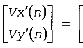

According to a method described in Japanese Patent No. 4111813, for example, a brushless motor is configured to include multiple Hall elements arranged with a
predetermined phase difference for detection of commutation timing. Hall elements for commutation in a most-typical three-phase brushless motor are arranged so as to output signals with a mutual phase difference of 120°. However, to detect a rotation angle of a rotor of a motor with the method described above, it is necessary to add a Hall element which output a signal having a 90-degree phase difference. Accordingly, a general-purpose motor unit made by assembling coils, a rotor, and Hall elements with the 120-degree phase difference together in one piece cannot be used. This also leads to an increase in cost.
For the above-described problem, in Japanese Laid-open Patent Application No. 2013-108971, a vector generating unit synthesizes sinusoidal signals having a 90-degree phase difference by performing operation given by Equations (3) on sinusoidal signals output from three Hall elements provided in a brushless motor with a phase difference of other than 90°. By performing the operation, a rotation angle of a rotor is detected without addition of a sensor.
(HAU - HA V)l i = Au s(e)(whenAu = Av)
HAU + HA V = Au * sin(0)
The method disclosed in Japanese Laid-open Patent Application No. 2013-108971 reduces an increase in cost. However, to control motion of the motor more minutely, it is desired to detect a rotation angle of the rotor or the like more accurately.
In view of the above, there is a need to provide an angle detection, device capable of detecting a rotation angle of a rotor of a motor accurately.
SUMMARY OF THE INVENTION
An angle detection device includes: an angle detection unit that detects a rotation angle of a rotor based on output signals of multiple magnetic sensors arranged so as to detect the rotation angle of the rotor of a motor and have a phase difference from each other, and an amplitude- fluctuation removing unit that removes an amplitude
fluctuation component contained in the output signals of the magnetic sensors and having a period corresponding to one turn of the rotor.
BRIEF DESCRIPTION OF DRAWINGS
FIG. 1 is a schematic configuration diagram of a motor unit including Hall elements.
FIG. 2 is a diagram illustrating differential signals output from the Hall elements.
FIG. 3 is a configuration diagram of an angle
detection device according to a first embodiment of the present invention.
FIGS. 4A and 4B illustrate a waveform of a Hall- element output signal onto which a third harmonic is
superimposed.
FIGS. 5A and 5B illustrate a waveform of Hall-element output signal onto which an amplitude fluctuation component having a period corresponding to one turn of a rotor is superimposed.
FIG. 6 is a diagram illustrating transformation from UVW axes to XY axes.
FIGS. 7A and 7B are diagrams illustrating logic for generating two-phase pulse signals.
FIG. 8 is a configuration diagram of a calculation circuit executing operation of the angle detection device illustrated in FIG. 3.
FIG. 9 is an explanatory diagram illustrating
relationship between a clock signal and a count value.
FIG. 10 is a table illustrating control timing for the calculation circuit illustrated in FIG. 8.
FIG. 11 is a configuration diagram of the angle generator illustrated in FIG. 3.
FIG. 12 is a configuration diagram of the sine-data generation unit illustrated in FIG. 11.
FIG. 13 is an overall configuration diagram of a motor driving device according to a second embodiment of the present invention.
FIG. 14 is a diagram illustrating conditions for generating a Hall signal.
FIG. 15 is a configuration diagram of an upper arm of the driving commutation circuit illustrated in FIG. 13.
FIG. 16 is a diagram illustrating operations of the modulation unit illustrated in FIG. 13.
FIG. 17 is a diagram illustrating the Hall signals and phase logic of rectangular pulse driving.
FIG. 18 is a diagram illustrating relationship between phase logic and gate signals.
FIG. 19 is a cross-sectional view illustrating an example of an image forming apparatus according to a third embodiment of the present invention.
FIG. 20 is a diagram illustrating waveforms of two- phase sinewave signals having a 90-degree phase difference.
FIG. 21 is a diagram illustrating an example operation of an angle search algorithm according to a conventional technique.
DESCRIPTION OF EMBODIMENTS
First Embodiment
A first embodiment of the present invention is
described below with reference to FIGS. 1 to 12. FIG. 1 is a schematic configuration diagram of a motor unit including Hall elements. FIG. 2 is a diagram illustrating
differential signals output from the Hall elements. FIG. 3 is a configuration diagram of an angle detection device according to the first embodiment of the present invention'. FIGS. 4A and 4B illustrate a waveform of a Hall-element output signal onto which a third harmonic is superimposed. FIGS. 5A and 5B illustrates a waveform of a Hall-element output signal onto which an amplitude fluctuation component having a period corresponding to one turn of a rotor is superimposed. FIG. 6 is a diagram illustrating
transformation from UV axes to XY axes. FIGS. 7A and 7B are diagrams illustrating logic for generating two-phase pulse signals. FIG. 8 is a configuration diagram of a calculation circuit executing operation of the angle detection device illustrated in FIG. 3. FIG. 9 is an explanatory diagram illustrating relationship between a clock signal and a count value. FIG. 10 is a table
illustrating control timing for the calculation circuit illustrated in FIG. 8. FIG. 11 is a configuration diagram
of the angle generator illustrated in FIG. 3. FIG. 12 is a configuration diagram of the sine-data generation unit illustrated in FIG. 11.
As illustrated in FIG. 1, a brushless motor 10
includes Y-connected three-phase coils 13U, 13V, 13W (not shown in FIG. 1; see FIG. 13), which are composed of three phase of a U-phase, a V-phase, and a W-phase, having a mutual phase difference of 120°. The brushless motor 10 further includes a rotor 11 positioned to face the coils 13U, 13V, and 13W and including a permanent magnet
containing alternately arranged south and north poles. An electric current (drive current) , which is appropriately commutated according to a rotation angle, is supplied to each of the coils 13U, 13V, and 13W from coil terminals 12U, 12V, and 12W, respectively, thereby rotationally driving the brushless motor 10 (which will be described in detail later) . As illustrated in FIG. 1, the permanent magnet of the rotor 11 according to the present embodiment contains 12 poles (the number of pole pairs is 6) .
As illustrated in FIG. 1, three Hall elements 15U, 15V, and 15 serving as multiple magnetic sensors are fixedly arranged near the rotor 11 to detect a rotational angular position of the rotor 11. The Hall elements 15U, 15V, and 15W output differential signals HU+/HU- of the U-phase, HV+/HV- of the V-phase, and HW+/HW- of the W-phase,
respectively, which vary with a change in the magnetic field of the rotor 11 by utilizing the Hall effect in germanium or InSb. Analog Hall signals Hu, Hv, and Hw are obtained by single-ending the differential signals HU+/HU-, HV+/HV-, and HW+/HW-. "Single-ending" denotes converting a differential signal into a single-ended signal. As
illustrated in FIG. 2, the analog Hall signals Hu, Hv, and Hw sinusoidally vary as the rotor 11 rotates. The Hall
elements 15U, 15V, and 15W are arranged so that waveforms of the analog Hall signals Hu, Hv, and Hw have a mutual phase difference of 120°. FIG. 2 illustrates the three phase signals on the assumption that they are equal in amplitude.
At this time, the number of the magnetic poles of the rotor 11 according to the present embodiment is 12.
Accordingly, each of the sinewaves illustrated in FIG. 2 repeats six cycles in one turn of the rotor 11. Conversely, a one-sixth turn of the rotor 11 corresponds to one cycle of each of the sinewaves illustrated in FIG. 2. For the sake of convenience of description, a rotation angle (Θ) of the rotor 11 of the brushless motor 10 is given in degrees where 360 is one cycle of the sinewave of each of the analog Hall signals Hu, Hv, and Hw. Accordingly, an actual rotation angle (mechanical angle) of the rotor 11 of the brushless motor 10 is one sixth of the value (Θ: electrical angle) given in degrees where 360 is one cycle of the sinewaves of the analog Hall signals Hu, Hv, and Hw in this manner. For example, when the value (Θ) of the rotation angle given in degrees where 360 is one cycle of the
sinewaves of the analog Hall signals Hu, Hv, and Hw in this manner is 360°, the actual rotation angle of the rotor 11 of the brushless motor 10 is a one-sixth of 360°, or 60°.
To drive each of the Hall elements 15U, 15V, and 15W, it is necessary to apply a voltage perpendicularly to a direction, in which the differential signal is output, and to a direction of to-be-detected magnetic flux.
Illustration thereof is .omitted from FIG. 2. The Hall elements 15U, 15V, and 15W correspond to the multiple sensors that output the sinusoidal signals which vary with the rotation angle of the rotor and differ from each other
in phase due to positions of the Hall elements 15U, 15V, and 15W.
A configuration of an angle detection device 20 according to the present embodiment is described below with reference to FIG. 3. The angle detection device 20 broadly includes a differential amplifier 22, an analog-to-digital (A/D) converter 23, a harmonic removing unit 24, an
amplitude-fluctuation removing unit 25, a vector generation unit 30, a vector rotation unit 40, an angle generator 50, and a two-phase-pulse generation unit 65.
Upon receiving differential signals from the Hall elements 15U, 15V, and 15W of the brushless motor 10, the differential amplifier 22 converts the U-phase differential signal HU+/HU- and the V-phase differential signal HV+/HV- into the single-ended, analog Hall signals Hu and Hv, respectively, and outputs the analog Hall signals. At this time, waveforms of the analog Hall signals Hu and Hv are expressed by Equations (4) which represent waveforms of differential outputs of the three-phase Hall elements.
More specifically, the waveforms are expressed by two sinusoidal functions, which differ in phase, of the
rotation angle Θ of the rotor 11 (hereinafter, simply referred to as "rotation angle Θ") given in degrees where 360 is one cycle of the sinewaves of the analog Hall signals Hu and Hv as described above. Amplitudes of Hu and Hv are denoted as Au and Av, respectively. In the present embodiment, although description is given by way of example where the two phases are the U phase and the V phase, the two phases may alternatively be the W phase and the U phase or the W phase- and the V phase.
(
HAU= Au * sin Θ +
3
( (4)
HAV= Au * sin Θ -
3,
The analog Hall signals Hu and Hv single-ended by the differential amplifier 22 are then converted by the A/D converter 23 into digital Hall signals Ru and Rv. The harmonic removing unit 24 removes the third harmonic from the digital Hall signals Ru and Rv.
The third harmonic is a sinewave having a period three times that of the fundamental as illustrated in FIG. 4A. A Hall signal, in which the third harmonic is superimposed on the fundamental, exhibits such a waveform as that
illustrated in FIG. 4B. Because the period of the third harmonic is three times that of the fundamental, when the rotation angle Θ is 30°, the waveform is distorted in the positive direction by the amplitude of the third harmonic, while when the rotation angle Θ is 90°, the waveform is distorted in the negative direction by the amplitude.
Accordingly, the amplitude of the third harmonic can be estimated from the value of the Hall signal at 30° and that at 90°.
Regarding the estimation of the amplitude, for example, the amplitude of the third harmonic can be calculated by solving simultaneous equations based on that the amplitude of the third harmonic is added to the Hall signal at 30° and is subtracted from the Hall signal at 90°. Further, the phase difference between the Hall signal and the rotation angle is necessary to remove the third harmonic. This phase difference can be obtained as follows, for example. For example, by studying the magnitude of the Hall signal and studying the location of the peak of the Hall signal based on a difference between the current
magnitude and the preceding magnitude, because the phase of the Hall signal at the location is 90°, the phase
difference can be obtained as the difference between the rotation angle at the peak and 90°.
Assuming that the current rotation angle is denoted by
Θ, phase differences uO and vO between the rotation angle Θ, and the digital Hall signals Ru and Rv, and third harmonic gains A3u and A3v are to be obtained in advance. The effect of the third harmonic can be removed by subtracting the sine value calculated from these values or, more
specifically, the sine value of an angle three times
(integral multiple of) the rotation angle of the rotor 11, from the digital Hall signals Ru and Rv as given by
Equations (5). In the present embodiment, multiplication by three is performed because what is to be removed is the third harmonic component. The rotation angle Θ having the same period as the Hall signal is present in the angle detection device 20 as detected angle data 0d, which will be described later. Accordingly, in Equations (5), the phase differences between the rotation angle Θ, and the digital Hall signals Ru and Rv are denoted by uO and vO, respectively.
DuO = Ru - A3u x sin(3(0 - uO))
DvO = Rv - A3v x sin(3(0 - vO))

Subsequently, the amplitude-fluctuation removing unit 25 removes an amplitude fluctuation component having a period corresponding to one turn of the rotor 11. The inventor found that an amplitude fluctuation component having a period corresponding to one turn of the rotor 11 is superimposed on the output signal (i.e., Hall signal) of the Hall element as a result of analysis of the Hall signal. The amplitude fluctuation component having the period
corresponding to one turn of the rotor 11 (hereinafter, "amplitude fluctuation component") is superimposed on the Hall signal illustrated in FIG. 5A in such a manner that a fluctuation wave having a period that is an integral multiple of (in the present embodiment, six times) that of the Hall signal is superimposed on the Hall signal in a multiplied manner to exhibit the waveform illustrated in FIG. 5B. Examples causing this include eccentricity of a rotating shaft of the brushless motor 10. The inventor also found that such an amplitude fluctuation component can be a noise component in detection of the rotation angle of the rotor 11 of the brushless motor 10 and deteriorate detection accuracy of the rotation angle.
The effect of such an amplitude fluctuation component can be removed by calculating the following Equations (6), where DuO and DvO are digital Hall signals from which the third harmonic component is removed, ul and vl are phase differences between the amplitude fluctuation component, and the digital Hall signals Ru and Rv, K' is an amount of amplitude fluct

Regarding equations (6), assuming that K1 is the amplitude fluctuation amount, fluctuation occurs at a period of one-six of the rotation angle Θ, and ul, vl is . the phase difference between the amplitude fluctuation and the Hall signal, the signal in FIG. 5B is obtained by multiplying the digital Hall signal Ru by K1 xsin ( (Θ/6) -ul) , and thus the original digital Hall signal Ru is obtained by multiplying the inverse thereof. Put another way,
Equations (6) multiply the digital Hall signals DuO and DvO by a sine value of one-sixth (integral submultiple) of the
rotation angle of the rotor 11.
Subsequently, the vector generation . unit 30 serving as a vector conversion unit obtains an X-axis component Dx and a Y-axis component Dy of the vector on a rectangular XY plane, with respect to digital Hall signals Du and Dv from which the third harmonic component and the amplitude fluctuation component are removed. The X-axis component Dx and the Y-axis component Dy are obtained from the following Equations ( 7 ) .

Here, the meanings of respective Equations (7) are described below with reference to FIG. 6. A U-axis and a V-axis are laid on the rectangular XY plane in an
orientation of +60° and an orientation of -60° with respect to the X-axis, respectively. Letting U and V represent a unit vector having a length of 1 on the U-axis and a unit vector having a length of 1 on the V-axis, respectively, a vector (U+V) is a unit vector X on the X axis, and a vector (U-V) is a vector having a length of V3 on the Y axis.
That is, Equation (7), which are expressions representing interoperation of Du and Dv, represent coordinate
transformation from the UV-coordinate system to the XY- coordinate system. (HAU-HAV) is multiplied by 1/V3 (which is indicated by G in FIG. 3) to cause a transformed vector to have an equal length.
Subsequently, the vector rotation unit 40 serving as a rotation calculation unit performs rotation transformation on the vector represented by the X-axis component Dx and the Y-axis component Dy in accordance with a value of detected angle data Θ, which will be described later, and outputs resultant values as a rotated X-axis component Xdsh
and a rotated Y-axis component Ydsh.
The rotated X-axis component Xdsh is a value obtained by adding a result of multiplication of the X-axis
component Dx and a cosine value cos9 and a result of
multiplication of the Y-axis component Dy and a sine value sin9. Put another way, Xdsh=cos9xDx+sin9xDy is calculated. The rotated Y-axis component Ydsh is a value obtained by subtracting a result of multiplication of the X-axis
component Dx and the sine value sineG from a result of multiplication of the Y-axis component Dy and the cosine value cos9. Put another way, Ydsh=-sin9xDx+cos9xDy is calculated.
The calculation expressed by Equation (8) is linear transformation that rotates the vector (Vx,Vy) by the angle Θ clockwise to a vector (Vx',Vy')- X' and Y' are obtained from Equation (8) as X 1 =cos9xX+sin9xY and Y ' =-sin9xX+cos9xY, respectively. As with the calculation using Equation (8), the above-described operation performed by the vector rotation unit 40 corresponds to rotating the vector
represented by the X-axis component Vx and the Y-axis component Vy by the value of the detected angle data Θ clockwise. The sine value sin9 and the cosine value cos9 correspond to reference sinewaves having multiple phases.


The angle generator 50 serving as a detection unit corrects the detected angle data 9d indicating the rotation angle of the rotor 11 based on the rotated Y-axis component Ydsh in such a manner that if the sign of the rotated Y- axis component Ydsh is positive, the detected angle data 9d is corrected in the positive direction, while if the sign
of the rotated Y-axis component Ydsh is negative, the detected angle data 9d is corrected in the negative
direction. This will be described in detail later.
That is, the vector generation unit 30, the vector rotation unit 40, and the angle generator 50 described above make up an angle detection unit.
The two-phase-pulse generation unit 65 updates ENCA and ENCB, which are two-phase pulse signals, based on the least-significant two bits of the detected angle data 6d in accordance with, for example, generation logic illustrated in FIG. 7A. As a result, the two-phase pulse signals ENCA and ENCB as those illustrated in FIG. 7A are output. A central processing unit (CPU) (not shown) or the like reads the two-phase pulse signals ENCA and ENCB and performs rotation control of the brushless motor 10. FIG. 7B illustrates an example where the. detected angle data 6d is 8-bit data.
The configuration illustrated in FIG. 3 can, when provided with a clock generator which generates a clock having a period that is several times shorter than a sampling interval of the A/D converter 23, perform data processing multiple cycles during the sampling interval of the A/D converter 23. However, the configuration
illustrated in FIG. 3 where multiple multipliers, adders, and subtracters are arranged is disadvantageously large in circuit scale. Inexpensive configuration which is reduced in circuit scale can be achieved by arranging only a single multiplier and a single adder-subtracter and supplying to- be-calculated input data to the multiplier and the adder- subtractor in a time dividing manner. An example of this configuration is illustrated in FIG. 8.
A calculation circuit 100 illustrated in FIG. 8
performs the various calculations of the harmonic removing unit 24, the amplitude-fluctuation removing unit 25, the vector generation unit 30, and the vector rotation unit 40 illustrated in FIG . 3. The calculation circuit 100
includes selectors 101, 102, 103, 104, 105, and 108, a multiplier 106, an adder-subtracter 107, register files 109 and 111, demultiplexers 110 and 112, and a calculation control circuit 113.
The selector 101 selectively outputs one of the
digital Hall signals Ru and Rv which are output from the
A/D converter 23, the third harmonic gains A3u and A3v, the coefficient K for use in removal of the amplitude
fluctuation component (Equations (3) and (4)), G
representing 1/V3, and calculation results of sinG, cosG, sin (3 (θ-uO) ) , sin ( 3 (θ-νθ ) ) , sin(0/6-ul), and sin (θ/6-ul ) .
Each of the calculation results of sinB, cosG, sin ( 3 (θ-uO ) ) , sin (3 (θ-νθ) ) , sin(9/6-ul), and sin(9/6-ul) is fed from the angle generator 50.
The selector 102 selectively outputs either the output of the selector 101 or an output of the register file 109 to an input MA, which is one of inputs to the multiplier 106. The selector 103 selectively outputs either the output of the selector 101 or the output of the register file 109 to an input MB, which is the other one of the inputs to the multiplier 106. The selector 104 selectively outputs either the output of the selector 101 or the output of the register file 109 to an input A, which is one of inputs to the adder-subtracter 107. The selector 105 selectively outputs either the output of the selector 101 or the output of the register file 109 to an input B, which is the other one of the inputs to the adder-subtracter 107. The selector 108 selectively outputs either an output P of
the multiplier 106 or an output Z of the adder-subtracter 107.
The calculation control circuit 113 controls which input is to be selected by each of the selectors 101, 102, 103, 104, 105, and 108.
The multiplier 106 multiplies the output of the selector 102 and the output of the selector 103 and outputs a multiplication result as the output P. The' adder- subtracter 107 performs addition or subtraction of the output of the selector 104 and the output of the selector
105 and outputs the calculation result as the output Z. An addition-subtraction switch signal alu_op is fed to the adder-subtracter 107 from the calculation control circuit 113.
The register file 109 includes four registers denoted by R0 to R3 where calculation results of the multiplier 106 and the adder-subtracter 107 are to be temporarily stored. The register file 111 includes a register XDSH and a register YDSH where the rotated X-axis component Xdsh and the rotated Y-axis component Ydsh are to be stored,
respectively. The register files 109 and 111 may be independent registers or implemented by a memory such as a RAM.
The demultiplexer 110 outputs the output of the selector 108 to one of the registers R0 to R3 of the register file 109. The demultiplexer 112 outputs the output of the selector 108 to one of the register. XDSH and the register YDSH of the register file 111.
The calculation control circuit 113 controls operation of the calculation circuit 100 based on a counter value sent of a control counter (not shown) and a sampling signal fs of the A/D converter 23. More specifically, the
calculation control circuit 113 controls selection to be
made by the selectors 101, 102, 103, 104, 105, and 108, switching between addition and subtraction of the adder- subtracter 107, selection to be made by the demultiplexers 110 and 112, and the like.
Control timing for the calculation control circuit 113 is described below. In the present embodiment, an example where control is provided based on a clock having a period that is 20 times shorter than the sampling interval (the sampling signal fs) of the A/D converter 23 is described. To generate signals for use in controlling operations of the calculation circuit 100 with appropriate timing, the calculation control circuit 113 causes the control counter described above to repeatedly count 20 cycles as
illustrated in FIG. 9 as "0, 1, 2, 19, 0, 1, 2,... 19, 0, 1, 2,
The clock (elk) illustrated in FIG. 9 is generated by an oscillator (not shown) or the like. The control counter generates the counter value sent from 0 to 19 based on this clock. The sampling signal fs may be generated by
frequency-dividing the clock signal or, alternatively, generated by another oscillator.
The control timing may be provided as follows. Each of selector switch signals, the addition-subtraction switch signal alu_op, and demultiplexer switch signals (store signals to the registers R0, Rl, R2 , R3, XDSH, and YDSH) are output so that calculations are performed as
illustrated in FIG. 10, for example. As a result,
calculations corresponding to the operation order of the harmonic removing unit 24, the amplitude-fluctuation removing unit 25, the vector generation unit 30, and the vector rotation unit 40 as illustrated in FIG. 3 can be performed .
The table illustrated in FIG. 10 contains respective
columns representing SCNT (the counter value sent) , the input MA of the multiplier 106, the input MB of the
multiplier 106, the input A of the adder-subtracter 107, the input B of the adder-subtracter 107, the addition- subtraction switch signal alu_op, .the register R0, the register Rl, the register R2, the register R3, the register XDSH, and the register YDSH. The table indicates what is to be input to the inputs, the registers, and the like of the respective columns for each of SCNT values. For instance, the table indicates that at SCNT=0, the third harmonic gain A3u is input to the input MA, which is one of the inputs to the multiplier 106, sin(3(6-u0)) is input to the input MB, which is the other one of the inputs, and the output P of the multiplier 106 is input to the register R0. The table indicates that at SCNT=1, the digital Hall signal Ru is input to the input A, which is one of the inputs to the adder-subtracter 107, the value of the register R0 is input to the input B, which is the other one of the inputs, and the output Z of the adder-subtracter 107 is input to the register R0.
In short, the upper one of Equations (5) is calculated by the operations at SCNT=0 and SCNT=1. Accordingly, calculation corresponding to that performed by the harmonic removing unit 24 is performed by the operations at SCNT=0 through 3; calculation corresponding to that performed by the amplitude-fluctuation removing unit 25 is performed by the operations at SCNT=4 through 7; calculation
corresponding to that performed by the vector generation unit 30 is performed by the operations at SCNT=8 through 10; calculation corresponding to that performed by the vector rotation unit 40 is performed by the operations at SCNT=11 through 16. This makes it possible to construct a circuit to include only a single multiplier and a single
adder-subtracter, thereby reducing circuit scale and cost.
FIG. 11 illustrates a configuration of the angle generator 50. The angle generator 50 includes an angle detection unit 51 and a sine-data generation unit 52. The angle detection unit 51 includes a count determination unit 51a, a counter 51b, and an operation determination unit 51c.
The count determination unit 51a increments the
counter 51b when the value of the rotated Y-axis component Ydsh, which is output from the vector rotation unit 40, is positive (larger than 0) but decrements the counter 51b when the value is negative. The counter 51b is a counter which outputs the detected angle data 9d. In other words, because the detected angle data 0d is the output of the counter 51b, precision (resolution) depends on the number of bits of the counter. For instance, when the counter 51b is configured to output 8-bit data expressing a rotation angle from 0 to 360°, 1 least significant bit (LSB)
represents 360°/256«l.4°.
The operation determination unit 51c determines
whether or not the control counter value sent is 19 and, when the control counter value sent is 19, outputs an enable signal which allows increment or decrement of the counter 51b, or the like. That is, the angle detection unit 51 of the angle generator 50 is operated when all the calculations of the calculation circuit 100 are completed as illustrated in FIG. 10. As described above, the angle detection unit 51 increments or decrements the counter 51b depending on whether the value of the rotated Y-axis
component Ydsh is positive or negative and outputs a
counter value of when the value of the rotated Y-axis component Ydsh is 0, as the detected angle data 6d.
The configuration of the angle detection unit 51 is
not limited to that described above. Alternatively, the angle detection unit 51 may be configured to use an
approximate search algorithm based on a bisection method. In a system which permits initial convergence time, a method of converging to actually-detected angle data by incrementing or decrementing the counter 51b only by one for a single data piece and continuing calculation for successive data pieces may be used.
FIG. 12 illustrates a configuration of the sine-data generation unit 52 serving as a sine value generation unit. The sine-data generation unit 52 includes a selector 52a, a first processing unit 52b, a sine wave table 52c, and a second processing unit 52d.
The selector 52a makes selection from the detected angle data 9d which is output from the angle detection unit 51, the value of (θ+90°) , the value of 3(9-u0), the value of 3(θ-ν0), the value of (θ/6-ul), and the value of (Θ/6- vl) based on the control counter value sent and outputs the selected value. Meanwhile, of the inputs to the selector 52a, 9d of other than the detected angle data 9d is denoted as Θ; this is because 9=9d. Each of the value of 3(9-u0), the value of 3(9-v0), the value of (θ/6-ul), and the value of (θ/6-vl) is calculated in advance from the phase
differences uO and vO with respect to the pre-given digital Hall signals Ru and Rv, and the phase differences ul and vl between the amplitude fluctuation component and the digital Hall signals Ru. and Rv. Meanwhile, because cosine data can be obtained by advancing sine data by 90°, an angle of 90° is added. For instance, when an angle is expressed in 8 bits, 256/4=64 is to be added.
The selector 52a selects an output based on the counter value sent to output each input data described
above with required timing. For instance, when the counter value sent is 0, the selector 52a selects the value of 3 (Θ- uO) . In other words, the selector 52a makes selection from the inputs and outputs the selected input in a time
dividing manner. Accordingly, the sine-data generation unit 52 outputs sinB, cos9, sin ( 3 (θ-uO ) ) , si ( 3 (θ-νθ ) ) , sin(6/6-ul), and sin(9/6-vl) in a time dividing manner.
That is, the sine-data generation unit 52 outputs sine values of integral submultiples of the rotation angle of the rotor 11 and sine values of integral multiples of the rotation angle of the rotor 11 in a time dividing manner.
The first processing unit 52b obtains a sine value tbdata for angle data θ' selected by the selector 52a according to the following four conditions from the sine wave table 52c where sine values associated with angle data θ' are stored.
(1) If 0°<θ'<90°, the sine wave table 52c is referred to with the unprocessed angle data θ' as angle data.
(2) If 90°<θ'<180°, the sine wave table 52c is referred to with (180°-θ') as angle data.
(3) If 180°<θ'<270°, the sine wave table 52c is referred to with (θ'-180°) as angle data.
(4) If 270ο<θ'≤3β0°, the sine wave table 52c is referred to with (360°-θ') as angle data.
The operation described above makes it possible to obtain sine values of angles larger than 90° by making use of periodicity of trigonometric functions only by storing sine values of an angle range of 90° in a non-volatile memory or the like in advance as the sine wave table 52c for the angle data θ'.
If 180°<θ'<3β0ο, the second processing unit 52d
inverts the positive/negative sign of the sine value tbdata and outputs the sign-inverted value, but if 0°<θ'<180ο, the second processing unit 52d outputs unprocessed tbdata. In short, the second processing unit 52d outputs any one of sinG, cos9, sin ( 3 (θ-uO ) ) , sin (3 (θ-νθ) ) , sin(9/6-ul), and sin (θ/6-vl) .
According to the present embodiment, the angle
detection device 20 includes the amplitude-fluctuation removing unit 25 configured to remove the amplitude
fluctuation component contained in the output signals of the Hall elements 15U and 15V and having the period
corresponding to one turn of the rotor 11. This makes it possible to remove the amplitude fluctuation component contained in the output signals of the Hall elements 15U and 15V, thereby reducing noise component in detection of the rotation angle of the rotor 11. As a result, the rotation angle of the rotor 11 of the brushless motor 10 can be detected accurately.
The amplitude-fluctuation removing unit 25 removes the amplitude fluctuation component based on the output signals of the Hall elements 15U and 15V and a sine value of an integral submultiple of the rotation angle of the rotor 11. The amplitude fluctuation component is a component having a period depending on the number of pairs of the poles.
Accordingly, to perform correction in units of one turn of the rotor 11 of the brushless motor 10, the following relationship is to be held: (mechanical
angle) / (N/2 )= (electrical angle), where N is the number of magnetic poles of the rotor 11. According to this, a sine value of an angle which is a product of the electrical angle and N/2 is obtained, and multiplication by a gain, which is the inverse of amplitude fluctuation, is performed.
As a result, effect of the amplitude fluctuation can be removed.
Furthermore, the angle detection device 20 includes the harmonic removing unit 24 configured to remove a third harmonic component contained in the output signals of the Hall elements 15U and 15V. This makes it possible to remove the third harmonic component contained in the output signals of the Hall elements 15U and 15V, thereby further reducing the noise component in angle detection. As a result, the rotation angle of the rotor 11 of the brushless motor 10 can be detected more accurately.
The harmonic removing unit 24 removes the third harmonic component based on the output signals of the Hall elements 15U and 15V and a sine value of an integral multiple of the rotation angle of the rotor 11. More specifically, to cancel the effect of the third harmonic component, a sine value of an angle ( 3x ( (rotation angle) - (phase difference) ) ) is calculated from the phase
difference between a currently-estimated rotation angle of the rotor 11 and the Hall signal, a result of
multiplication between the sine value and a gain signal indicating a magnitude is subtracted from the output signals of the Hall elements 15U and 15V, and thereby effect of the third harmonic can be removed.
The angle detection device 20 includes the vector generation unit 30 configured to convert the digital Hall signal, from which the third harmonic component and the amplitude fluctuation component are removed, into a vector, the vector rotation unit 40 configured to rotate the vector by performing calculation of the vector generated by the vector generation unit 30 and the reference sinewaves having multiple phases, and the angle generator 50
configured to detect the rotation angle of the rotor 11
based on a result of the vector rotation unit 40. This makes it possible to synthesize sinusoidal signals having a 90-degree phase difference from sinusoidal signals output from the Hall elements and having a phase difference of other than 90° to thereby detect a rotation angle of the rotor 11.
The angle generator 50 included in the angle detection device 20 may be configured to output sinG, cosB, sin (3(6- uO) ) , sin (3 (θ-νθ) ) , sin(9/6-ul), and sin(0/6-vl) in a time dividing manner. This makes it possible to output each of the values at time when a corresponding sine value is required and, furthermore, shared use of calculation circuit, the sine wave table 52c, and the like.
The angle generator 50 stores data containing sine values of an angle range of 90° as the sine wave table 52c in advance. This makes it possible to reduce a capacity of a storage memory or the like.
Although the amplitude fluctuation component is removed after the third harmonic component has been removed in the configuration illustrated in FIG. 3, this order may be reversed. The harmonic to be removed is not limited to the third harmonic component. Any Nth order harmonic component (N is a natural number greater than 1) can be removed by applying the method of the present embodiment. A configuration not including the harmonic removing unit 24 may be employed. In a case where the configuration not including the harmonic removing unit 24 is employed, the digital Hall signals Ru and Rv output from the A/D
converter 23 are directly fed to the amplitude-fluctuation removing unit 25.
The present embodiment has been described based on the hardware configuration illustrated in FIGS. 3, 8, and 11.
Alternatively, a computer such as a CPU may be caused to function as the functions of the harmonic removing unit 24, the amplitude-fluctuation removing unit 25, the vector generation unit 30, the vector rotation unit 40, and the angle generator 50. More specifically, the present
embodiment may be provided as a computer program for
causing a. computer to perform an angle detection method including harmonic removal, amplitude fluctuation removal, and angle detection including vector generation, vector rotation,, and angle generation.
Second Embodiment
A second embodiment of the present invention is
described below with reference to FIGS. 13 to 18. Elements which are identical to those of the above-described first embodiment are denoted by like reference numerals and symbols, and repeated descriptions are omitted. FIG. 13 is an overall configuration diagram of a motor driving device according to the second embodiment of the present invention, FIG. 14 is a diagram illustrating conditions for generating a Hall signal. FIG. 15 is a configuration diagram of an upper arm of the driving commutation circuit illustrated in FIG. 13. FIG. 16 is a diagram illustrating operations of the modulation unit illustrated in FIG. 13. FIG. 17 is a diagram illustrating the Hall signals and phase logic of rectangular pulse driving. FIG. 18 is a diagram
illustrating relationship between phase logic and gate signals .
The present embodiment is a motor driving device 500 including the angle detection device 20 described in the first embodiment. Accordingly, the brushless motor 10, the Hall elements 15U, 15V, and 15 , and the angle detection device 20 are similar in configuration to those of the first embodiment.
The angle detection device 20 is the angle detection device 20 according the first embodiment described above and outputs the two-phase pulse signals ENCA and ENCB which vary with the rotation angle of the rotor 11 (see FIG. 3) . Although the angle detection device 20 illustrated in FIG. 13 does not output the detected angle data 9d, the angle detection device 20 may alternatively be configured to output the detected angle data 0d for utilization in
position control, rectangular signal driving, or the like.
A Hall comparator 83 connected to the brushless motor
10 and to the angle detection device 20 is a comparator which binarizes each of the differential signals of HU+/HU-, HV+/HV-, and HW+/HW- output from the corresponding Hall elements 15U, 15V, and 15 in accordance with the logic illustrated in FIG. 14. The Hall comparator 83 outputs the binarized signals as a Hall signal HG (HU,HV,H ). For example, if HU+ is equal to or larger than HU-, the Hall comparator 83 outputs a High-level signal as HG(HU) which is in the top column of FIG. 14, but if HU+ is smaller than HU-, the Hall comparator 83 outputs a Low-level signal.
The same applies to each of HG(HV) and HG(HW).
As illustrated in FIGS. 13 and 15, a driving
commutation circuit 85 includes upper arms 86 and lower arms 87 which are three-phase connected. Each of the upper arms 86 is connected to power supply voltage Vcc and
includes a switching element 88 and a diode 89 connected in parallel. The lower arms 87 are similar to the upper arms 86 in configuration but connected to ground GND. Each of the switching elements is driven by gate signals (UH, VH, WH, UL, VL, and WL) to apply a pulse-width-modulated
voltage to the coils 13U, 13V, and 13 of the brushless motor 10, thereby supplying a driving current to the coils 13U, 13V, and 13W and rotationally driving the brushless
motor 10.
A modulation unit 80 performs pulse width modulation (hereinafter, "P M") on a drive-voltage command value Vamp*, thereby generating PWM-phase gate signals XH and XL in accordance with predetermined logic.
Operations of the modulation unit 80 are described below with reference to FIG. 16.
A carrier wave Vc illustrated on the top region of FIG. 16 is a triangular wave having a predetermined PWM period and amplitude from the ground GND to the power supply voltage Vcc. The modulation unit 80 generates a PWM signal Xon illustrated in the second region from the top of FIG. 16 based on a result of determination as to which is higher the amplitude command value Vamp* or the carrier wave Vc.
The modulation unit 80 then generates the PWM-phase gate signal XH, which is a signal delayed by td from the PWM signal Xon as illustrated in the third and fourth regions from the top of FIG. 16, to be fed to the switching elements 88 of the upper arms 86. The modulation unit 80 also generates the PWM-phase gate signal XL, which is obtained by inverting the PWM signal Xon with its rising edge (corresponding to a falling edge of Xon) delayed by double td, to be fed to the switching elements of the lower arms. Note that td denotes short-circuit prevention time (dead time) provided to prevent occurrence of a short circuit between the switching elements of the upper arm and the switching elements of the lower arm, and tpwm denotes the PWM period (i.e., the period of the carrier wave Vc) .
A configuration and operations of a commutation
control unit 81 are described below.
The commutation control unit 81 to which the PWM-phase gate signals XH and XL are input selects and outputs
appropriate gate signals to the U phase, V phase, and W
phase based on the High/Low logic of the Hall signal HG (HU,HV,HW) described above, respectively.
To rotationally drive a motor with rectangular waves, the commutation control unit 81 assigns one phase state of the PWM phase, a LOW phase, and a HiZ (high impedance) phase to each of the U phase, the V phase, and the W phase in accordance with a state of the Hall signal HG as
illustrated in FIG. 17. The commutation control unit 81 outputs gate signals depending on the phase state as follows.
As illustrated in FIG. 18, if the phase state is the PWM state, the commutation control unit 81 selects XH as a gate signal YH for the upper arm 86 and XL as a gate signal YL for the lower arm 87. If the phase state is the LOW phase, the commutation control unit 81 sets the gate signal YH for the upper arm 86 to invariably Lo (Low) and the gate signal YL for the lower arm 87 to invariably Hi (High) . If the phase state is the HiZ phase, the commutation control unit 81 sets both the gate signal YH for the upper arm 86 and the gate signal YL for the lower arm 87 to invariably
Lo(Low). Each of the switching elements 88 included in the driving commutation circuit 85 is conducted when the gate signal applied to the switching element 88 is Hi, but blocked when the gate signal is Lo. The gate signals YH and YL represent the gate signals UH and UL of the U phase, the gate signals VH and HL of the V phase, and the gate signals WH and WL of the W phase, respectively (see FIG. 13) .
These selections for the three phases are
simultaneously updated at start of the PWM period. A rotating direction can be reversed by selection in which the PWM phase and the LOW phase are interchanged from FIG. 17. An example commutating operation performed by the
driving commutation circuit 85 is described below.
For example, the phase logic of the first PWM period illustrated in FIG. 17 is such that: the U phase is the LOW phase, the V phase is the PWM phase, and the W phase is the Hiz phase. In this case, in the U phase, the switching element 88 of the upper arm 86 is blocked and the switching element of the lower arm 87 is conducted in accordance with the relationship illustrated in FIG. 18. In the V phase, the switching element 88 of the upper arm 86 is conducted for a fixed period of time, and the switching element of the lower arm 87 is blocked for a fixed period of time containing the fixed conduction period of the upper arm. In the W phase, the switching elements 88 of both the upper arm 86 and the lower arm 87 are blocked. As a result, a drive current flows from the V-phase coil 13V to the U- phase coil 13U through the switching element of the V-phase upper arm 86 and the switching element of the U-phase lower arm 87 over the above-described fixed conduction period of time. Consequently, the rotor 11 is driven by a torque generated by interaction between the drive current flowing through the coils 13V and 13U and a magnetic field of the permanent magnet of the rotor 11 illustrated in FIG. 1.
The phase logic of the next (second) PWM period illustrated in FIG. 17 is such that: the U phase is the LOW phase, the V phase is the Hiz phase, and the W phase is the PWM phase. In this case, a commutation operation similar to that described above is performed. . As a result, a drive current flows from the W-phase coil 13W to the U-phase coil 13U through the switching element of the W-phase upper arm 86 and the switching element of the U-phase lower arm 87 over the fixed conduction period of time during which the W-phase upper arm 86 is conducted. Consequently, the rotor 11 is driven by a torque generated by interaction between
the drive current flowing through the coils 13W and 13U and the magnetic field of the permanent magnet of the rotor 11 illustrated in FIG. 1.
The phase logic of the still next (third) P M period illustrated in FIG. 17 is such that: the U phase is the Hiz phase, the V phase is the LOW phase, and the W phase is the PWM phase. In this case, a commutation operation similar to that described above is performed. As a result, a drive current flows from the W-phase coil 13W to the V-phase coil 13V through the switching element of the W-phase upper arm 86 and the switching element of the V-phase lower arm 87 over the fixed conduction period of time during which the W-phase upper arm 86 in is conducted. Consequently, the rotor 11 is driven by a torque generated by interaction between the drive current flowing through the coils 13W and 13V and the magnetic field of the permanent magnet of the rotor 11 illustrated in FIG. 1.
In the following fourth PWM period illustrated in FIG. 17, over the fixed period of time during which the U-phase upper arm is conducted, a drive current flows from the U- phase coil 13U to the V-phase coil 13V through the
switching element of the U-phase upper arm 86 and the switching element of the V-phase lower arm 87. In the fifth PWM period, over the fixed period of time during which the U-phase upper arm is conducted, a drive current flows from the U-phase coil 13U. to the W-phase coil 13W through the switching element of the U-phase upper arm 86 and the switching element of the W-phase lower arm 87. In the sixth PWM period, over the fixed period of time during which the V-phase upper arm is conducted, a drive current flows from the V-phase coil 13V to the W-phase coil 13W through the switching element of the V-phase upper arm 86 and the switching element of the W-phase lower arm 87.
Thereafter, the pattern of the series of the PWM periods (six periods) illustrated in FIG. 17 is repeated. The rotor 11 is continuously rotated by the drive current appropriately supplied to each of the coils 13U, 13V, and 13W by the commutation operation performed by the driving commutation circuit 85. In short, the rotor 11 is
rotationally driven by application of a periodically- varying drive voltage to the coil terminals 12U, 12V, and 12W of the brushless motor 10.
According to the present embodiment, because the motor driving device 500 which drives the brushless motor 10 includes the angle detection device 20, angle detection can be performed accurately without requiring addition of another sensor such as an optical encoder.
Furthermore, output signals of the Hall elements 15U,
15V, and 15W, which are essentially provided in the
brushless motor 10 to drive the brushless motor 10 by commutation, can be utilized for the following purposes. That is, the output signals can be utilized not only for detection of timing for commutation by the Hall comparator 83, the commutation control unit 81, the driving
commutation circuit 85, and the modulation unit 80 but also can be utilized in detection of a rotation angle by the angle detection device 20. Because the need of adding another sensor such as an optical encoder is obviated, the motor driving device 500 including, in addition to a configuration for detection of the commutation timing, a configuration for the angle detection can be constructed less expensively. Meanwhile, the "configuration for detection of the commutation timing" denotes, in the example illustrated in FIG. 13, the configuration including the Hall comparator 83, the commutation control unit 81, the driving commutation circuit 85, and the modulation unit
80. The "configuration for the angle detection" denotes, for example, the configuration including the angle
detection device 20.
Third Embodiment
A third embodiment of the present invention is
described below with reference to FIG. 19. Elements which are identical to those of the above-described first
embodiment are denoted by like reference numerals and symbols, and repeated descriptions are omitted. FIG. 19 is a cross-sectional view illustrating an example of an image forming apparatus according to the third embodiment of the present invention.
An image forming apparatus 1000 illustrated in FIG. 19 is what is referred to as a tandem full-color image forming apparatus constructed as a copying apparatus by including an image reading unit. The copying apparatus according to the third embodiment includes an apparatus body 1100
mounted on a sheet feeding table 1200, a scanner 1300 arranged at an uppermost portion of the apparatus body 1100, and an automatic document feeder (ADF) 1400 arranged on the scanner 1300.
The scanner 1300 internally includes a first carriage 1310 made up of an illumination light source and a mirror, and a second carriage 1320 including a mirror. The first carriage 1310 and the second carriage 1320 are movable parallel to an exposure glass 1330. The second carriage 1320 employs a known optical system and travels at a speed half that of the first carriage 1310. The first carriage 1310 and the second carriage 1320 scan an image of a
stationary original document on the exposure glass 1330 while traveling. Light reflected from the original
document illuminated with light from the light source is converged through a condensing lens 1340 to form an image
and captured with a solid-state image sensor 1350 such as a charge coupled device (CCD) . The captured data is
processed by an image processing unit (not shown) of the apparatus body 1100.
An intermediate transfer belt 1010 is arranged at a substantially center portion of the apparatus body 1100. Four image forming units 1020 are arranged along a top surface of the intermediate transfer belt 1010. In each of the image forming units 1020, devices necessary for an electrophotographic process are arranged around a
photoconductor drum 1030.
The intermediate transfer belt 1010 is looped and stretched over multiple support rollers to be rotatable clockwise. Transfer rollers serving as a primary transfer unit are arranged on the inner side of the intermediate transfer belt 1010 at positions facing the photoconductor drums 1030 of the image forming units.
An exposure device 1040 is arranged above the image forming units 1020. The exposure device 1040 irradiates the photoconductor drum 1030 of each of the image forming units 1020 with writing light.
A transfer conveyance belt 1050 is arranged below the intermediate transfer belt 1010. One of rollers supporting the transfer conveyance belt 1050 functions as a secondary transfer roller and transfers, as secondary transfer, an image on the intermediate transfer belt 1010 onto a
recording medium (e.g., transfer paper).
A fixing device 1060 is arranged to the left of the transfer conveyance belt 1050. A sheet output tray 1070 is arranged on a side surface of the apparatus at a position to the left of the fixing device 1060. A sheet reversing unit 1080 is arranged at a lowermost portion of the
apparatus body 1100. The sheet feeding table 1200 includes
sheet feeding cassettes 1210 and 1220 stacked in two layers.
When making a copy using the full-color copying
apparatus illustrated in FIG. 19, a user places an original document on the original document table of the ADF 1400 or on the exposure glass 1330 of the scanner. When a start switch arranged on an operating panel (not shown) is
pressed, the scanner 1300 is driven to read document
information by causing light emitted from the light source and reflected off the original document to be reflected from the mirrors so that reflected light enters reading sensor (the solid-state image sensor 1350) through the condensing lens 1340.
When the start switch arranged on the operating panel is pressed, the intermediate transfer belt 1010 is
rotationally driven by a drive motor (not shown) .
Simultaneously, the photoconductor drums 1030 of the image forming units 1020 are rotated and single-color images of black, yellow, magenta, and cyan are respectively formed on the photoconductor drums 1030. These single-color images are transferred onto the intermediate transfer belt 1010 one by one to form a composite color image.
The brushless motor 10 driven by the motor driving device 500 described above with reference to FIG. 13 can be used as the drive motor (not shown) which rotationally drives the intermediate transfer belt 1010. The motor driving device 500 can be used as the motor driving device which drives the brushless motor 10 serving as the drive motor. In this case, although not illustrated in FIG. 19, the motor driving device 500 is included in the image forming apparatus 1000.
When the start switch is pressed, a sheet is picked up and delivered from the sheet feeding table 1200 and caused to abut on registration rollers 1260 to be temporarily
stopped.
The registration rollers 1260 are rotated with timing matched to the composite color image on the intermediate transfer belt 1010, the sheet is delivered to between the intermediate transfer belt 1010 and the transfer conveyance belt 1050, and the image is transferred and the color image is recorded on the sheet at a secondary transfer section. The sheet onto which the image has been transferred is delivered to the fixing device 1060 where a toner image is fixed. Then, the sheet is discharged onto the sheet output tray 1070.
According to the third embodiment, the brushless motor 10 is used as the drive motor which rotationally drives the intermediate transfer belt 1010 and the like of the image forming apparatus 1000, and the motor driving device 500 is used as the drive device of the brushless motor 10.
Accordingly, accurate angle detection can be performed without requiring addition of another sensor such as an optical encoder. Therefore, the drive motor of the image forming apparatus 1000 can be driven accurately.
The motor described in each of the embodiments
described above is not limited to an outer rotor type.
Alternatively, the motor may be of an inner rotor type. Connection pattern of the coils is not limited to the Y connection (star connection) and may alternatively be delta connection. The number of poles of the motor's rotor is not limited to 12. The arrangement of the Hall elements is not limited to that with the 120-degree phase difference.
The motor driving device of the present invention is suitably applicable to household electrical appliances, office automation (OA) equipment, and the like. Examples of the OA equipment to which the motor driving device is applicable include not only the image forming apparatus
described above but also an image reading apparatus.
The image forming units in the image forming apparatus can have any desired configuration. The image forming units of the respective colors may be arranged in an
arbitrary order in the tandem image forming apparatus . The configuration of the image forming apparatus is not limited to the tandem type. Alternatively, a configuration in which multiple developing devices are arranged around a single photoconductor or a configuration adopting a
revolver type developing device can be employed. The present invention is applicable to a full-color image forming apparatus using toner of three colors, a multiple- color image forming apparatus using toner of two colors, or a monochrome image forming apparatus. As a matter of course, the image forming apparatus is not limited to a copying apparatus and may alternatively be a printer, a facsimile, or a multifunction peripheral having multiple functions .
The invention is not to be limited to the specific embodiments described above. Those skilled in the art will recognize that the invention can be modified in various manners within the scope of the present invention. The various modifications and other embodiments are intended to be included within the scope of the present invention so long as including the configuration of the angle detection device, the motor driving device, or the image forming apparatus according to an aspect of the present invention.
According to an aspect of the present invention, an angle detection device capable of detecting a rotation angle of a rotor of a motor accurately can be provided.
Although the invention has been described with respect to specific embodiments for a complete and clear disclosure, the appended claims are not to be thus limited but are to
be construed as embodying all modifications and alternative constructions that may occur to one skilled in the art that fairly fall within the basic teaching herein set forth.
REFERENCE SIGNS LIST
10 brushless motor (motor)
11 rotor
15U, 15V Hall elements (magnetic sensors)
20 angle detection device
24 harmonic removing unit .
25 amplitude-fluctuation removing unit
30 angle generation unit (vector conversion unit, angle detector)
40 vector rotation unit (rotation calculator, angle detector)
.50 angle generator (angle detector)
51 angle detection unit (detector)
52 sine-data generation unit (sine value generation unit)
500 motor driving device
1000 image forming apparatus
Claims
1. An angle detection device comprising:
an angle detection unit that detects a rotation angle of a rotor based on output signals of multiple magnetic sensors arranged so as to detect the rotation angle of the rotor of a motor and have a phase difference from each other, and
an amplitude-fluctuation removing unit that removes an amplitude fluctuation component contained in the output signals of the magnetic sensors and having a period
corresponding to one turn of the rotor.
2. The angle detection device according to claim 1, further comprising a harmonic removing unit that removes an Nth harmonic component (N is a natural number equal to or greater than 2) contained in the output signals of the magnetic sensors.
3. The angle detection device according to claim 2, further comprising
a sine value generation unit that outputs a sine value of an integral submultiple of the rotation angle of the rotor and a sine value of an integral multiple of the rotation angle of the rotor in a time dividing manner, wherein
the amplitude-fluctuation removing unit removes the amplitude fluctuation component having the period
corresponding to one turn of the rotor based on the output signals of the magnetic sensors and the sine value of the integral submultiple of the rotation angle of the rotor output by the sine value generation unit, and
the harmonic removing unit removes the Nth harmonic component based on the output signals of the magnetic
sensors and the sine value of the integral multiple of the rotation angle of the rotor output by the sine value generation unit.
4. The angle detection device according to claim 3, wherein data containing sine values of an angle range of 90° associated with the rotation angle is stored in the sine value generation unit in advance.
5. A motor driving device that rotationally drives a motor by applying a periodically-varying drive voltage to coil terminals of the motor, the motor driving device comprising the angle detection device according to any one of claims 1 to 4.
6. The motor driving device according to claim 5, wherein the multiple magnetic sensors are arranged near the rotor, and
the motor is driven by commutation based on the output signals of the multiple magnetic sensors.
7. An image forming apparatus comprising the motor driving device according to claim 5 or 6.
8. An angle detection method comprising:
detecting a rotation angle of a rotor of a motor based on output signals of multiple magnetic sensors arranged so as to detect the rotation angle of the rotor and have a phase difference from each other, and
removing an amplitude fluctuation component contained in the output signals of the magnetic sensors and having a period corresponding to one turn of the rotor.
Applications Claiming Priority (2)
| Application Number | Priority Date | Filing Date | Title |
|---|---|---|---|
| JP2013-245625 | 2013-11-28 | ||
| JP2013245625A JP6432129B2 (en) | 2013-11-28 | 2013-11-28 | Angle detection device and angle detection method |
Publications (1)
| Publication Number | Publication Date |
|---|---|
| WO2015080299A1 true WO2015080299A1 (en) | 2015-06-04 |
Family
ID=53199232
Family Applications (1)
| Application Number | Title | Priority Date | Filing Date |
|---|---|---|---|
| PCT/JP2014/082186 Ceased WO2015080299A1 (en) | 2013-11-28 | 2014-11-28 | Angle detection device, angle detection method, motor driving device, and image forming apparatus |
Country Status (2)
| Country | Link |
|---|---|
| JP (1) | JP6432129B2 (en) |
| WO (1) | WO2015080299A1 (en) |
Cited By (2)
| Publication number | Priority date | Publication date | Assignee | Title |
|---|---|---|---|---|
| CN112230055A (en) * | 2020-07-07 | 2021-01-15 | 北京新能源汽车技术创新中心有限公司 | A built-in permanent magnet rotor magnetic field harmonic detection device and detection method |
| CN115694084A (en) * | 2021-07-23 | 2023-02-03 | 禾一电子科技有限公司 | Electronic rotary encoder |
Citations (5)
| Publication number | Priority date | Publication date | Assignee | Title |
|---|---|---|---|---|
| JPH03284186A (en) * | 1990-03-28 | 1991-12-13 | Japan Servo Co Ltd | Magnetic encoder for brushless servomotor |
| JP2006042537A (en) * | 2004-07-29 | 2006-02-09 | Japan Servo Co Ltd | Brushless dc motor added with magnetic encoder and signal processing circuit |
| JP2012189375A (en) * | 2011-03-09 | 2012-10-04 | Jtekt Corp | Rotation angle detection apparatus |
| JP2012194086A (en) * | 2011-03-17 | 2012-10-11 | Minebea Co Ltd | Three-phase brushless motor |
| JP2013108971A (en) * | 2011-10-25 | 2013-06-06 | Ricoh Co Ltd | Angle detector, motor drive device, and image forming apparatus |
Family Cites Families (2)
| Publication number | Priority date | Publication date | Assignee | Title |
|---|---|---|---|---|
| JP3234177B2 (en) * | 1997-07-01 | 2001-12-04 | ファナック株式会社 | Position control device |
| WO2010138155A2 (en) * | 2009-05-27 | 2010-12-02 | Active Precision, Inc. | Encoder interpolator with enhanced precision |
-
2013
- 2013-11-28 JP JP2013245625A patent/JP6432129B2/en not_active Expired - Fee Related
-
2014
- 2014-11-28 WO PCT/JP2014/082186 patent/WO2015080299A1/en not_active Ceased
Patent Citations (5)
| Publication number | Priority date | Publication date | Assignee | Title |
|---|---|---|---|---|
| JPH03284186A (en) * | 1990-03-28 | 1991-12-13 | Japan Servo Co Ltd | Magnetic encoder for brushless servomotor |
| JP2006042537A (en) * | 2004-07-29 | 2006-02-09 | Japan Servo Co Ltd | Brushless dc motor added with magnetic encoder and signal processing circuit |
| JP2012189375A (en) * | 2011-03-09 | 2012-10-04 | Jtekt Corp | Rotation angle detection apparatus |
| JP2012194086A (en) * | 2011-03-17 | 2012-10-11 | Minebea Co Ltd | Three-phase brushless motor |
| JP2013108971A (en) * | 2011-10-25 | 2013-06-06 | Ricoh Co Ltd | Angle detector, motor drive device, and image forming apparatus |
Cited By (3)
| Publication number | Priority date | Publication date | Assignee | Title |
|---|---|---|---|---|
| CN112230055A (en) * | 2020-07-07 | 2021-01-15 | 北京新能源汽车技术创新中心有限公司 | A built-in permanent magnet rotor magnetic field harmonic detection device and detection method |
| CN115694084A (en) * | 2021-07-23 | 2023-02-03 | 禾一电子科技有限公司 | Electronic rotary encoder |
| US12055419B2 (en) * | 2021-07-23 | 2024-08-06 | Hoyi Electronic Technology Co., Ltd. | Electronic rotary encoder |
Also Published As
| Publication number | Publication date |
|---|---|
| JP2015102525A (en) | 2015-06-04 |
| JP6432129B2 (en) | 2018-12-05 |
Similar Documents
| Publication | Publication Date | Title |
|---|---|---|
| JP2013108971A (en) | Angle detector, motor drive device, and image forming apparatus | |
| US9903740B2 (en) | Rotation-angle detecting device, image processing apparatus, and rotation-angle detecting method | |
| US8405329B2 (en) | Motor drive controller and image forming apparatus incorporating the motor drive controller | |
| US9294021B2 (en) | Control device, driving device, and image forming apparatus | |
| US9255817B2 (en) | Rotation-angle detection device, image processing apparatus, and rotation-angle detection method | |
| US6826499B2 (en) | Method and apparatus for calibrating and initializing an electronically commutated motor | |
| CN111801883B (en) | Position estimation method, position estimation device, and motor module | |
| US9435664B2 (en) | Rotation angle detector, rotation angle detection method, and image forming apparatus | |
| JPH05344779A (en) | Current control device and arithmetic device | |
| JP6844617B2 (en) | Motor modules, motor step motion control systems, and motor controls | |
| WO2015080299A1 (en) | Angle detection device, angle detection method, motor driving device, and image forming apparatus | |
| JP5845828B2 (en) | Detection device, drive device | |
| JP2012257429A (en) | Motor driving control apparatus and image forming apparatus | |
| JP2020150590A (en) | Motor control unit, method for estimating initial position of magnetic pole of rotor, and image forming apparatus | |
| JP2017135881A (en) | Angle estimation device, motor drive device, motor drive system with the same, image forming apparatus applying the same, and carrier device | |
| US9473054B2 (en) | Angle detection apparatus, motor driving control apparatus and angle detection method | |
| JP6205683B2 (en) | Rotation angle detection device, image processing device, and rotation angle detection method | |
| JP2020150656A (en) | Motor control unit, method for estimating initial position of magnetic pole of rotor, and image forming apparatus | |
| CN110247604A (en) | A kind of permanent magnet synchronous motor sinusoidal drive method | |
| JP5621960B2 (en) | Motor drive device and image forming apparatus | |
| JPH10117489A (en) | Phase controller | |
| JP3134707B2 (en) | Motor position and speed detector | |
| JP2019154236A (en) | Controller, drive unit, and image forming apparatus | |
| JP2016065796A (en) | POSITION DETECTION DEVICE, MOTOR DRIVE DEVICE, AND IMAGE PROCESSING DEVICE | |
| JP2023064794A (en) | Control system for angle detector and AC rotating machine |
Legal Events
| Date | Code | Title | Description |
|---|---|---|---|
| 121 | Ep: the epo has been informed by wipo that ep was designated in this application |
Ref document number: 14866679 Country of ref document: EP Kind code of ref document: A1 |
|
| NENP | Non-entry into the national phase |
Ref country code: DE |
|
| 122 | Ep: pct application non-entry in european phase |
Ref document number: 14866679 Country of ref document: EP Kind code of ref document: A1 |