WO2015079508A1 - Gas turbine suitable for renewable energy and control method thereof - Google Patents
Gas turbine suitable for renewable energy and control method thereof Download PDFInfo
- Publication number
- WO2015079508A1 WO2015079508A1 PCT/JP2013/081831 JP2013081831W WO2015079508A1 WO 2015079508 A1 WO2015079508 A1 WO 2015079508A1 JP 2013081831 W JP2013081831 W JP 2013081831W WO 2015079508 A1 WO2015079508 A1 WO 2015079508A1
- Authority
- WO
- WIPO (PCT)
- Prior art keywords
- power generation
- gas turbine
- generation system
- generator
- shaft
- Prior art date
Links
- 238000000034 method Methods 0.000 title claims description 23
- 239000007789 gas Substances 0.000 claims abstract description 143
- 238000010248 power generation Methods 0.000 claims abstract description 109
- 239000000446 fuel Substances 0.000 claims abstract description 32
- 239000000567 combustion gas Substances 0.000 claims abstract description 17
- 230000008859 change Effects 0.000 claims description 23
- 230000003247 decreasing effect Effects 0.000 claims description 6
- 230000007423 decrease Effects 0.000 description 20
- 238000005259 measurement Methods 0.000 description 16
- 230000006870 function Effects 0.000 description 9
- 238000002485 combustion reaction Methods 0.000 description 7
- 238000013461 design Methods 0.000 description 6
- 238000012821 model calculation Methods 0.000 description 6
- 230000005611 electricity Effects 0.000 description 5
- 238000001816 cooling Methods 0.000 description 4
- 238000010586 diagram Methods 0.000 description 4
- 230000005855 radiation Effects 0.000 description 4
- 230000033228 biological regulation Effects 0.000 description 3
- 230000005540 biological transmission Effects 0.000 description 3
- 238000004422 calculation algorithm Methods 0.000 description 3
- 230000000694 effects Effects 0.000 description 3
- 230000008569 process Effects 0.000 description 3
- 238000012545 processing Methods 0.000 description 3
- CURLTUGMZLYLDI-UHFFFAOYSA-N Carbon dioxide Chemical compound O=C=O CURLTUGMZLYLDI-UHFFFAOYSA-N 0.000 description 2
- 238000013528 artificial neural network Methods 0.000 description 2
- 230000009286 beneficial effect Effects 0.000 description 2
- 238000004364 calculation method Methods 0.000 description 2
- 238000005516 engineering process Methods 0.000 description 2
- 239000000295 fuel oil Substances 0.000 description 2
- 238000011084 recovery Methods 0.000 description 2
- 230000004044 response Effects 0.000 description 2
- 230000002195 synergetic effect Effects 0.000 description 2
- 238000010521 absorption reaction Methods 0.000 description 1
- 238000013459 approach Methods 0.000 description 1
- 229910002092 carbon dioxide Inorganic materials 0.000 description 1
- 239000001569 carbon dioxide Substances 0.000 description 1
- 210000003792 cranial nerve Anatomy 0.000 description 1
- 238000013480 data collection Methods 0.000 description 1
- 230000003111 delayed effect Effects 0.000 description 1
- 239000002803 fossil fuel Substances 0.000 description 1
- 238000009434 installation Methods 0.000 description 1
- 238000012423 maintenance Methods 0.000 description 1
- 238000003062 neural network model Methods 0.000 description 1
- 239000010742 number 1 fuel oil Substances 0.000 description 1
- 238000002407 reforming Methods 0.000 description 1
- 238000005070 sampling Methods 0.000 description 1
- 230000007480 spreading Effects 0.000 description 1
- 230000003068 static effect Effects 0.000 description 1
- 230000001629 suppression Effects 0.000 description 1
Images


Classifications
-
- F—MECHANICAL ENGINEERING; LIGHTING; HEATING; WEAPONS; BLASTING
- F02—COMBUSTION ENGINES; HOT-GAS OR COMBUSTION-PRODUCT ENGINE PLANTS
- F02C—GAS-TURBINE PLANTS; AIR INTAKES FOR JET-PROPULSION PLANTS; CONTROLLING FUEL SUPPLY IN AIR-BREATHING JET-PROPULSION PLANTS
- F02C3/00—Gas-turbine plants characterised by the use of combustion products as the working fluid
- F02C3/04—Gas-turbine plants characterised by the use of combustion products as the working fluid having a turbine driving a compressor
- F02C3/10—Gas-turbine plants characterised by the use of combustion products as the working fluid having a turbine driving a compressor with another turbine driving an output shaft but not driving the compressor
-
- F—MECHANICAL ENGINEERING; LIGHTING; HEATING; WEAPONS; BLASTING
- F02—COMBUSTION ENGINES; HOT-GAS OR COMBUSTION-PRODUCT ENGINE PLANTS
- F02C—GAS-TURBINE PLANTS; AIR INTAKES FOR JET-PROPULSION PLANTS; CONTROLLING FUEL SUPPLY IN AIR-BREATHING JET-PROPULSION PLANTS
- F02C6/00—Plural gas-turbine plants; Combinations of gas-turbine plants with other apparatus; Adaptations of gas- turbine plants for special use
-
- F—MECHANICAL ENGINEERING; LIGHTING; HEATING; WEAPONS; BLASTING
- F02—COMBUSTION ENGINES; HOT-GAS OR COMBUSTION-PRODUCT ENGINE PLANTS
- F02C—GAS-TURBINE PLANTS; AIR INTAKES FOR JET-PROPULSION PLANTS; CONTROLLING FUEL SUPPLY IN AIR-BREATHING JET-PROPULSION PLANTS
- F02C7/00—Features, components parts, details or accessories, not provided for in, or of interest apart form groups F02C1/00 - F02C6/00; Air intakes for jet-propulsion plants
- F02C7/36—Power transmission arrangements between the different shafts of the gas turbine plant, or between the gas-turbine plant and the power user
-
- F—MECHANICAL ENGINEERING; LIGHTING; HEATING; WEAPONS; BLASTING
- F02—COMBUSTION ENGINES; HOT-GAS OR COMBUSTION-PRODUCT ENGINE PLANTS
- F02C—GAS-TURBINE PLANTS; AIR INTAKES FOR JET-PROPULSION PLANTS; CONTROLLING FUEL SUPPLY IN AIR-BREATHING JET-PROPULSION PLANTS
- F02C9/00—Controlling gas-turbine plants; Controlling fuel supply in air- breathing jet-propulsion plants
- F02C9/26—Control of fuel supply
- F02C9/28—Regulating systems responsive to plant or ambient parameters, e.g. temperature, pressure, rotor speed
-
- F—MECHANICAL ENGINEERING; LIGHTING; HEATING; WEAPONS; BLASTING
- F03—MACHINES OR ENGINES FOR LIQUIDS; WIND, SPRING, OR WEIGHT MOTORS; PRODUCING MECHANICAL POWER OR A REACTIVE PROPULSIVE THRUST, NOT OTHERWISE PROVIDED FOR
- F03D—WIND MOTORS
- F03D9/00—Adaptations of wind motors for special use; Combinations of wind motors with apparatus driven thereby; Wind motors specially adapted for installation in particular locations
- F03D9/20—Wind motors characterised by the driven apparatus
- F03D9/25—Wind motors characterised by the driven apparatus the apparatus being an electrical generator
- F03D9/255—Wind motors characterised by the driven apparatus the apparatus being an electrical generator connected to electrical distribution networks; Arrangements therefor
-
- H—ELECTRICITY
- H02—GENERATION; CONVERSION OR DISTRIBUTION OF ELECTRIC POWER
- H02P—CONTROL OR REGULATION OF ELECTRIC MOTORS, ELECTRIC GENERATORS OR DYNAMO-ELECTRIC CONVERTERS; CONTROLLING TRANSFORMERS, REACTORS OR CHOKE COILS
- H02P9/00—Arrangements for controlling electric generators for the purpose of obtaining a desired output
- H02P9/04—Control effected upon non-electric prime mover and dependent upon electric output value of the generator
-
- F—MECHANICAL ENGINEERING; LIGHTING; HEATING; WEAPONS; BLASTING
- F05—INDEXING SCHEMES RELATING TO ENGINES OR PUMPS IN VARIOUS SUBCLASSES OF CLASSES F01-F04
- F05B—INDEXING SCHEME RELATING TO WIND, SPRING, WEIGHT, INERTIA OR LIKE MOTORS, TO MACHINES OR ENGINES FOR LIQUIDS COVERED BY SUBCLASSES F03B, F03D AND F03G
- F05B2220/00—Application
- F05B2220/70—Application in combination with
- F05B2220/704—Application in combination with the other apparatus being a gas turbine
-
- F—MECHANICAL ENGINEERING; LIGHTING; HEATING; WEAPONS; BLASTING
- F05—INDEXING SCHEMES RELATING TO ENGINES OR PUMPS IN VARIOUS SUBCLASSES OF CLASSES F01-F04
- F05B—INDEXING SCHEME RELATING TO WIND, SPRING, WEIGHT, INERTIA OR LIKE MOTORS, TO MACHINES OR ENGINES FOR LIQUIDS COVERED BY SUBCLASSES F03B, F03D AND F03G
- F05B2270/00—Control
- F05B2270/30—Control parameters, e.g. input parameters
- F05B2270/337—Electrical grid status parameters, e.g. voltage, frequency or power demand
-
- F—MECHANICAL ENGINEERING; LIGHTING; HEATING; WEAPONS; BLASTING
- F05—INDEXING SCHEMES RELATING TO ENGINES OR PUMPS IN VARIOUS SUBCLASSES OF CLASSES F01-F04
- F05D—INDEXING SCHEME FOR ASPECTS RELATING TO NON-POSITIVE-DISPLACEMENT MACHINES OR ENGINES, GAS-TURBINES OR JET-PROPULSION PLANTS
- F05D2270/00—Control
- F05D2270/01—Purpose of the control system
- F05D2270/06—Purpose of the control system to match engine to driven device
- F05D2270/061—Purpose of the control system to match engine to driven device in particular the electrical frequency of driven generator
-
- F—MECHANICAL ENGINEERING; LIGHTING; HEATING; WEAPONS; BLASTING
- F05—INDEXING SCHEMES RELATING TO ENGINES OR PUMPS IN VARIOUS SUBCLASSES OF CLASSES F01-F04
- F05D—INDEXING SCHEME FOR ASPECTS RELATING TO NON-POSITIVE-DISPLACEMENT MACHINES OR ENGINES, GAS-TURBINES OR JET-PROPULSION PLANTS
- F05D2270/00—Control
- F05D2270/30—Control parameters, e.g. input parameters
- F05D2270/331—Mechanical loads
-
- Y—GENERAL TAGGING OF NEW TECHNOLOGICAL DEVELOPMENTS; GENERAL TAGGING OF CROSS-SECTIONAL TECHNOLOGIES SPANNING OVER SEVERAL SECTIONS OF THE IPC; TECHNICAL SUBJECTS COVERED BY FORMER USPC CROSS-REFERENCE ART COLLECTIONS [XRACs] AND DIGESTS
- Y02—TECHNOLOGIES OR APPLICATIONS FOR MITIGATION OR ADAPTATION AGAINST CLIMATE CHANGE
- Y02E—REDUCTION OF GREENHOUSE GAS [GHG] EMISSIONS, RELATED TO ENERGY GENERATION, TRANSMISSION OR DISTRIBUTION
- Y02E10/00—Energy generation through renewable energy sources
- Y02E10/70—Wind energy
- Y02E10/72—Wind turbines with rotation axis in wind direction
-
- Y—GENERAL TAGGING OF NEW TECHNOLOGICAL DEVELOPMENTS; GENERAL TAGGING OF CROSS-SECTIONAL TECHNOLOGIES SPANNING OVER SEVERAL SECTIONS OF THE IPC; TECHNICAL SUBJECTS COVERED BY FORMER USPC CROSS-REFERENCE ART COLLECTIONS [XRACs] AND DIGESTS
- Y02—TECHNOLOGIES OR APPLICATIONS FOR MITIGATION OR ADAPTATION AGAINST CLIMATE CHANGE
- Y02E—REDUCTION OF GREENHOUSE GAS [GHG] EMISSIONS, RELATED TO ENERGY GENERATION, TRANSMISSION OR DISTRIBUTION
- Y02E20/00—Combustion technologies with mitigation potential
- Y02E20/16—Combined cycle power plant [CCPP], or combined cycle gas turbine [CCGT]
Definitions
- the present invention in combination with a renewable energy and a power generator using a gas turbine, particularly satisfies the requirements of a system to be connected by suppressing output fluctuations, and improves the output and efficiency of the gas turbine according to operating conditions.
- the present invention relates to a control apparatus and method.
- Thermal power plants mainly generate power by driving power generation equipment based on the combustion heat extracted from fossil fuel by combustion, but there are various devices depending on the combination of fuel and power generation equipment. For example, coal or heavy oil is burned in a boiler, steam is generated with the combustion heat, a steam turbine is driven to generate electricity, the atmosphere is compressed with a compressor, and fuel and compressed air are mixed and burned in a combustor, A gas turbine power generator that generates power by driving the gas turbine with the combustion air, or a combined gas generator that uses the exhaust gas burned in the gas turbine to generate steam in the exhaust heat recovery boiler and drive the steam turbine with the steam. There is a cycle power generator.
- Patent Document 1 in a power system in which a plurality of power sources having different capacities such as gas engines and gas turbine generators and thermoelectric loads are connected to an unstable power source of wind power generation or solar power generation, a power generation command corresponding to the system load is provided. And a control device that adjusts the amount of exhaust heat recovery and the amount of heat stored in the thermoelectric load.
- Patent Document 2 describes an apparatus and a control method thereof when electric power obtained by wind power generation is combined with a complex plant such as heavy oil reforming.
- An object of the present invention is to provide a power generation system with high followability to load fluctuations.
- the present invention provides a compressor that compresses air to generate compressed air, a combustor that generates combustion gas from the compressed air and fuel, and a high-pressure turbine that is driven by the combustion gas.
- a power generator having a gas generator, a low-pressure turbine driven by the gas discharged from the gas generator, a main generator that generates electric power with the rotational force of the low-pressure turbine and supplies electric power to the system, and the gas generator,
- the control device includes: It receives the load target of the system and the load fluctuation factor of the system and outputs a control signal of the frequency converter. And features.
- 1 is a two-shaft gas turbine power generator according to an embodiment of the present invention. It is an example of the operation
- FIG. 4 is an initial screen displayed on the image display device according to the embodiment of the present invention. It is a screen which displays the driving
- FIG. 1 is a diagram for explaining a main device of a two-shaft gas turbine power generator according to this embodiment.
- the two-shaft gas turbine 27 is configured to include the gas generator 15, the power turbine 16, the GT control device 7 a, and the frequency converter 10.
- the power turbine 16 is configured to include the low-pressure turbine 2b, the low-pressure turbine shaft 12b, and the generator 5. In the case of power generation, in order to make the power frequency substantially constant, the power turbine 16 rotates at a substantially constant rotation speed, and drives the generator 5 at a substantially constant rotation speed. The electric power generated by the generator 5 is transmitted to the electric power consumer through the electric power cable.
- the gas generator 15 includes a compressor 1, a combustor 20, a high-pressure turbine 2a, a sub-motor / generator 6 that is an electric motor / generator, and a gas generator shaft 12a.
- the gas generator 15 has a structure that is mechanically separated from the power turbine 16. Therefore, it can be rotationally driven at a rotational speed different from that of the power turbine.
- Compressor 1 draws in air and compresses it to generate compressed air 21.
- the intake port of the compressor 1 is provided with an IGV (Inlet Guide Vane: inlet guide vane) 9.
- IGV Inlet Guide Vane: inlet guide vane
- the IGV 9 changes its opening area by rotating itself. The amount of air flowing into the compressor 1 can be changed by changing the opening.
- the amount of air flowing into the compressor 1 can be adjusted by the rotational speed of the gas generator 15.
- the combustor 20 generates the combustion gas 22 by mixing and burning the compressed air 21 and fuel generated by the compressor 1 in the burner 18.
- the combustion gas 22 first flows into the high-pressure turbine 2 a through the combustor liner 19.
- the fuel burned in the burner 18 is adjusted by a fuel flow control valve 8 provided in the fuel pipe.
- the high-pressure turbine 2 a obtains a rotational force by the energy of the high-temperature and high-pressure combustion gas 22.
- the rotational force is transmitted to the compressor 1 through the gas generator shaft 12a, and the compressor 1 is rotationally driven.
- the combustion gas 22 flows into the low pressure turbine 2b of the power turbine 16 after extracting a part of energy in the high pressure turbine 2a.
- the low-pressure turbine 2b obtains a rotational force from the energy of the combustion gas 22, transmits the rotational force to the generator 5 through the low-pressure turbine shaft 12b, and drives the generator 5 to rotate.
- the combustion gas 22 that has passed through the low-pressure turbine is discharged as exhaust 14.
- a part of the air compressed by the compressor 1 is extracted as turbine cooling air 23 and supplied to the high-pressure turbine 2 a and the low-pressure turbine 2 b without passing through the combustor 20.
- a part of the cooling air 23 is used for cooling the stationary blades 24 and the moving blades 25 constituting the turbine 2.
- the auxiliary motor / generator 6 connected to the high-pressure turbine shaft 12a is connected to the power system via the frequency converter 10, and adjusts the operation of the high-pressure turbine shaft by transferring power to and from the power system. can do. Specifically, by supplying electric power from the frequency converter 10, the auxiliary motor / generator 6 operates as a motor and supplies energy to the high-pressure turbine shaft 12a. Conversely, by extracting electric power with the frequency converter 10, the sub motor / generator operates as a generator, and the energy of the high-pressure turbine shaft 12a can be reduced.
- the controller 7a receives inputs including the high pressure turbine speed detected by the high pressure turbine speed detector 26a, the low pressure turbine speed detected by the low pressure turbine speed detector 26b, and an output command (MWD), and the fuel flow rate. It operates to send a signal including an FFD signal for controlling the control valve 8, a CIGV signal for controlling the opening degree of the IGV 9, and an IMWD signal for controlling the output power of the frequency converter 10.
- the control device 7a may be configured to have various protection functions.
- the rotational speed of the high-pressure turbine shaft 12a is decreased, the rotational energy of the shaft is released as electric power, and the output is decreased. In some cases, the rotational speed of the high-pressure turbine shaft 12a is increased so that electric power can be stored as rotational energy of the shaft.
- the output changing means not depending on the fuel flow rate, it is possible to obtain a high output changing speed while avoiding a decrease in life due to thermal fatigue or the like.
- the frequency converter 10 according to the present embodiment can have a smaller capacity than that for adjusting the output of the entire gas turbine.
- the low-pressure turbine responsible for most of the output rotates at a constant speed.
- the rotation speed adjustment by the frequency converter 10 is performed on the high-pressure turbine side that performs variable speed operation, and thus the capacity of the frequency converter 10 can be reduced.
- the frequency converter 10 having a capacity of 10% of the rated output. Thereby, the cost of the frequency converter 10 can be reduced.
- this control method includes a change in the number of revolutions of the gas generator and a change in the compressor intake air flow rate by adjusting the opening of the IGV 9. For example, when the rotational speed is higher than the set value, the power consumption of the compressor 1 increases and the rotational speed decreases by increasing the opening of the IGV 9 and increasing the compressor intake air flow rate. Conversely, the rotational speed of the gas generator 15 can be increased by reducing the opening of the IGV 9.
- the two-shaft gas turbine 27 operates as follows.
- the GT control device 7a sends a fuel flow rate command (FFD) to the fuel flow rate control valve 8, supplies necessary fuel to the combustor 20, and outputs the generator 5 and the low-pressure turbine. Balance recovered energy in 2b.
- the rotation speed of the power turbine 16 is controlled to be substantially constant.
- the GT control device 7a adjusts the opening degree of the IGV 9 so that the energy recovered by the high-pressure turbine 2a and the energy necessary for driving the compressor 1 are balanced and the rotation speed of the gas generator 15 is optimized. Control.
- the rotational speed of the gas generator 15 is not uniquely determined with respect to the output, but can be changed.
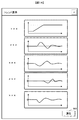
- the operation of the gas turbine according to this embodiment will be described with reference to FIG.
- the left column shows the operation when the demand fluctuation is small in the gas turbine according to the prior art
- the center column shows the operation when the demand fluctuation is large in the conventional technology
- the right column shows the operation when the demand fluctuation is large in the gas turbine according to the present embodiment.
- the power demand, GT output, system frequency, high-pressure shaft rotation speed, and low-pressure shaft rotation speed are shown as the vertical axis in order from the top row of each column. All horizontal axes show time.
- the frequency converter 10 is used to extract the shortage of the output change due to the fuel flow rate from the sub motor / generator. Although the electric power is insufficient only by the control based on the fuel flow rate, with this configuration, the rotational speed of the high-pressure turbine shaft 12a is reduced, and the rotational energy is converted into electric power to compensate for the shortage. At this time, the opening degree of the IGV 9 is determined so that the power of the compressor 1 and the recovered power of the high-pressure turbine 2a are balanced at the reduced rotational speed. The output frequency of the high-pressure turbine shaft 12a is converted into a reference frequency by the frequency converter 10. By doing so, it is possible to stabilize the frequency of the system even when the demand changes suddenly.
- the frequency converter 10 a known inverter / converter or the like can be used.
- the control device controls the IGV 9 so as to suppress the fluctuation in the flow rate of the air flowing through the compressor 1 when the rotation speed of the gas generator 15 fluctuates due to the operation of the frequency converter 10. Driving becomes possible.
- the efficiency of the compressor 1 is improved.
- the rotational speed is lowered while increasing the fuel flow rate when the output is increased
- the compressor efficiency is improved
- the discharge air temperature of the compressor 1 is lowered
- the driving power of the compressor 1 is also lowered. Therefore, in addition to the increase in output due to the increase in fuel, the output also increases due to the decrease in drive power of the compressor 1.
- the temperature of the combustion gas 22 also decreases due to the decrease in the discharge air temperature, the gas temperature change accompanying the output change can be reduced, and the reliability can be improved.
- the operating point is set so that the compressor efficiency increases when the rotational speed decreases and the compressor efficiency decreases when the rotational speed increases based on the state where the frequency converter 10 does not convert the frequency. You may set it. By doing so, the same beneficial synergistic effect as described above can be obtained.
- Fig. 3 shows an example of wind power generation as renewable energy.
- the wind power generation facility 30 includes a plurality of wind power generators 31.
- the wind power generation equipment is provided with an anemometer for measuring the wind condition, and is configured to control the blade pitch and the windmill direction (yaw) according to the wind condition. Power is generated by receiving a wind speed above a certain level, and when the wind is strong, the pitch is changed so that the blade does not receive the wind and stops.
- the characteristics of the power generation output with respect to the wind speed depend on the design of the wind power generator.
- the wind condition information obtained by the wind turbine generator and the measurement signal or control signal necessary for control are accumulated in the control device 200 as signals 120 and 130.
- the two-shaft gas turbine power generator 100 is controlled to a desired state in response to the control signal 150 from the controller 200.
- the state quantity of each part of the two-shaft gas turbine power generation device 100 is taken into the control device 200 as a measurement signal 140.
- the control device 200 performs control by operating various operation ends so as to be in an appropriate operation state with respect to the power generation request based on the measurement signal 140 from the gas turbine power generation device.
- the related information database 300 stores information for predicting wind power generation and grasping the current situation.
- the operation information database 600 stores measurement signals 120 and 140 obtained from the wind power generation facility 10 and the gas turbine power generation device 100, respectively. The form of these data will be described in detail later.
- the model calculation unit 400 calculates an output value when a predicted value of the wind power generation output or a signal that cancels the fluctuation of the wind power generation is input to the two-shaft gas turbine from the information obtained from the measurement signal.
- examples of data necessary for calculating a predicted value of wind power generation output include atmospheric information such as outside air temperature and humidity, wind speed, wind power generator output, and the like. The form of these data will be described in detail later.
- the control unit 500 outputs an appropriate control signal 130 based on the result of the model calculation unit. Based on this control signal, the air amount and fuel flow rate of the two-shaft gas turbine are manipulated to control the output. The same applies to the control signal of the frequency converter. Signals and information generated in these control devices are also output to the maintenance tool 910 as necessary. The algorithm for obtaining the control signal will be described in detail later.
- a user related to the two-shaft gas turbine power generation device 100 uses the input device 900 configured by the keyboard 901 and the mouse 902 and the support tool 910 connected to the image display device 950, so Information can be seen. In addition, information in the control device 200 can be accessed.
- the support tool 910 includes an external input interface 920, a data transmission / reception processing unit 930, and an external output interface 940.
- the input signal 800 generated by the input device 900 is taken into the support tool 910 via the external input interface 920.
- Information from the control device 200 is also taken in by the external input interface 920 in the same manner.
- the data transmission / reception processing unit 930 processes the input signal 801 in accordance with the information of the input signal 800 from the user, and transmits it as an output signal 802 to the external output interface 940.
- the output signal 803 is displayed on the image display device 950.
- FIG. 4 is a diagram showing a format of information on the climatic state.
- the items shown in this figure are not limited to wind power generation, but are also assumed to include cases where a natural energy-based power generation system such as solar power generation is included.
- a feature of the natural energy-based power generation system is that output fluctuation is not constant because it depends on wind and sunlight.
- time, weather, temperature, wind direction, wind speed, humidity, and solar radiation are stored in each row.
- the period of time is determined by a measurable time width.
- the weather is expressed using 15 types sent to the general public by the Japan Meteorological Agency.
- the wind direction is generally 16 directions, but the international style uses 360 directions that are divided into 360 degrees in the clockwise direction with true north as a reference.
- 360 azimuths are represented, but even in 16 azimuths, if a ratio of 22.5 degrees is given to each azimuth, it can be numerically expressed in degrees in the same manner.
- FIG. 5 is a diagram for explaining the mode of information stored in the driving information database 600.
- information measured by the wind power generation facility and the two-shaft gas turbine power generation facility is stored together with each measurement time for each measuring instrument.
- the PID number is a unique number assigned to each measurement value so that the data stored in the driving information database 600 can be easily used.
- the alphabet below it is a symbol indicating the measurement target. For example, the flow rate value F, the temperature value T, the pressure value P, the power generation output value E, and the concentration value D.
- data is stored at a cycle of 1 second, but the sampling cycle of data collection varies depending on the target twin-shaft gas turbine power generation facility.
- This model is a model for obtaining the future wind power output from the wind conditions and the current wind power output.
- This model has an input layer, an intermediate layer, and an output layer, and each layer has a plurality of nodes. These nodes are linked from the input layer to the output layer, and a weighting coefficient representing the strength of the link is set. That is, there are as many weighting coefficients as the number of connections between nodes.
- This model is called a neural network, which simulates a human cranial nerve network.
- the correlation of the input value can be expressed as a model. This is called learning.
- learning When learning is completed, an input value is input to this model, and an output value can be estimated based on the correlation of the input value at that time.
- the function set for the node is generally an exponential function called a sigmoid function, but is not limited thereto.
- many algorithms have been devised that appropriately adjust the weighting factor during learning. In general, the back propagation method is used. Details of these calculation algorithms are described in "Basics and Practices, Neural Network, Shiro Usui et al., Corona".
- the parameters in the model are learned based on the data or design data accumulated in the past to construct the model. After the start of operation, prediction is performed based on the parameters obtained by learning, but if the difference between the predicted value and the measured value is larger than the set value, the model is learned again based on the data accumulated so far. To do.
- the length of the predicted time is determined by the power generation output characteristics of the two-shaft gas turbine. In other words, it is necessary to predict in advance the delay from when the load command is given until actual power generation. This also relates to the flowchart of FIG.
- the apparatus has a means for predicting fluctuations in power supply and demand, and is configured to change the rotation speed in accordance with the predicted value of fluctuations in power supply and demand, more appropriate control can be performed.
- a model expressing the dynamic characteristics of the two-shaft gas turbine 27 is set in advance.
- a dynamic characteristic model based on the mass balance of pressure and flow rate is used, but it is also possible to use a neural network model for predicting wind power output.
- the maximum load change rate of the gas turbine is set in the dynamic characteristic model of the two-shaft gas turbine.
- the output that cancels the wind power generation output, that is, the amount of power that should be covered by the two-shaft gas turbine power generation device is the amount obtained by subtracting the wind power generation output from the target constant load.
- the two-shaft gas turbine has a delay due to mechanical elements, the output is delayed with respect to the input load change pattern. For this reason, when the output values from the wind turbine generator and the two-shaft gas turbine 27 are combined, they do not exactly coincide with each other, and canceling leakage occurs. This is calculated using the previous dynamic characteristic model. In this case, the load is followed within the maximum load change rate set in the dynamic characteristic model, but the output at this time becomes the MWD to the two-shaft gas turbine as it is. The amount of cancellation leakage is IMWD given to the frequency converter.
- step 501 an error between the predicted value output from the model created by the wind power generation output prediction of the model calculation unit 400 and the current measured value is calculated. It is confirmed whether this is below a preset value. If it is below, the process proceeds to step 502, and if not, the process proceeds to step 504 to re-learn the model shown in FIG.
- step 502 a load target is generated from the connection conditions of the system. System connection conditions differ in different countries and regions. Many specify the load fluctuation range and the fluctuation range of the system frequency. If the system already has several power supplies connected to it, the system can absorb frequency fluctuations even if the gas turbine of this apparatus is rapidly changed. For this reason, it is sufficient to consider the load fluctuation suppression range.
- step 503 the predicted value of wind power generation is subtracted from the load target.
- step 505 the output value of wind power generation is subtracted from the load target. That is, the predicted value is not used.
- step 506 the value calculated in step 503 or 505 is input to the gas turbine model to calculate the model output value.
- step 507 the model output value calculated in step 506 is subtracted from the load target.
- step 508 the model output value is set to MWD, and the subtracted value is set to IMWD.
- step 509 the input load to the M / G is calculated based on the atmospheric temperature and the model output value.
- the mass flow rate of the compressed air input from the compressor decreases, so the power generation output decreases. This is shown in FIG.
- the power generation output is 100% (rated) at a certain design temperature, but the output decreases as the atmospheric temperature increases.
- the motor and the power generator function by supplying electricity or applying a load to the M / G connected to the compressor side.
- the output can be improved even when the atmospheric temperature is high. This is shown in FIG.
- the M / G input command is 0, that is, the power generation output decreases from 100% in a normal two-shaft gas turbine.
- electricity is supplied (to the right of the shaft)
- the driving force of the compressor increases, and even if the IGV opening is fully open, the amount of air taken in is further increased, so the mass flow rate can be increased and the output can be increased.
- the fuel temperature cannot be increased infinitely, but the combustion temperature rises when fuel is added due to the increase.
- the power generation efficiency is the same. As shown in FIG. 10, the efficiency decreases when operating with a partial load other than the rated load. This is because the compressor is designed to be most efficient at the rated point.
- the amount of assist to M / G is determined so that each is optimal in the atmospheric temperature state and the partial load state.
- the assist amount is determined to be the maximum value obtained by summing the increase amount of the power generation output and the increase amount of the power generation efficiency with respect to the increase of the assist amount.
- the assist amount is determined to be the maximum value obtained by summing the increase amount of the power generation output and the increase amount of the power generation efficiency with respect to the increase of the assist amount.
- it is not limited to the total value. You may select the assistance amount from which either one becomes the maximum. In this way, by receiving the input of the output value and the atmospheric temperature from the gas turbine dynamic characteristic model for calculating the gas turbine output value for an arbitrary input value, and performing the control to output the control signal of the frequency converter 10, The amount of assist can be adjusted.
- step 510 the assist amount calculated in the previous step is used as an M / G command.
- FIG. 11 to FIG. 14 are examples of screens displayed on the image display device 950.
- the user uses the keyboard 901 and the mouse 902 to execute an operation such as inputting a parameter value in a blank area on these screens.
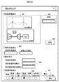
- FIG. 11 shows an initial screen displayed on the image display device 950.
- the user selects a necessary button from the operation state display button 951 and the trend display button 952, moves the cursor 953 using the mouse 902, and clicks the mouse 902 to display a desired screen.
- FIG. 12 is a screen for operating state display.
- the operation state display button 951 When the operation state display button 951 is clicked in FIG. 11, the screen of FIG. 12 is displayed.
- the system information display field 961 the user inputs time to be displayed on the image display device 950 into the time input field 962.
- various states at that time are displayed in the display column. Specifically, the state of the device such as the state quantity such as temperature and pressure at the currently measured location is displayed.
- the characteristic state display 964 shows the state of the determination set value in the flowchart shown in FIG.
- the setting condition 965 various conditions of the flowchart shown in FIG. 7 are displayed. Specifically, there are prediction tolerance, load fluctuation tolerance, and frequency fluctuation tolerance.
- an item to be displayed is selected by weather, temperature, wind direction, wind speed, humidity, and solar radiation amount, and the display button 967 is clicked to display the information in which the corresponding information is described. Search from the database 300 and display.
- FIG. 13 is a setting screen for displaying the trend on the image display device 950.
- the trend display button 952 is clicked in FIG. 11, the screen of FIG. 13 is displayed.
- the user inputs a measurement signal or an operation signal to be displayed on the image display device 950 into the input field 981 together with the range (upper limit / lower limit).
- the time to be displayed is input in the time input field 982.
- any of weather, temperature, wind direction, wind speed, humidity, and solar radiation amount is selected and the display button 985 is clicked, so that the information describing the corresponding information is displayed in the related information database 300.
- Search from and display As described above, the weather is expressed using 15 types transmitted to the general public by the Japan Meteorological Agency. A number is assigned according to each type, and this is displayed as a trend. That is, numbers are sequentially assigned up to 14, such as 0 for clear weather, 1 for clear weather, and 2 for light cloudiness.
- control device it is possible to assist the operator with better control by providing a function for the control device to output various signals to the display device so that the screen as described above can be displayed.
- the control device it is preferable because the operator can easily recognize the influence of the current operation on the load and the system.
- FIG. 15 is a diagram for explaining a gas turbine control apparatus and method for renewable energy according to the second embodiment including the main equipment shown in FIG. It targets solar power, not wind power.
- the solar power generation apparatus 1000 is a combination of a plurality of solar panels 1100.
- the model calculation unit 401 which is a prediction part of photovoltaic power generation, is different, and will be described in detail here.
- FIG. 16 a model for predicting a future power generation output from input data of temperature, humidity, solar radiation amount, and power generation output is obtained.
- the flow and operation related to the generation of other devices and MWD and the operation in the control unit are the same as those in the first embodiment. However, related measurement values may be different.
- a gas generator having a compressor 1 that compresses air to generate compressed air, a combustor 20 that generates combustion gas from the compressed air and fuel, and a high-pressure turbine 2 a that is driven by the combustion gas.
- a power turbine 16 having a low-pressure turbine 2 b driven by the gas discharged from the gas generator 15, a main generator 5 that generates electric power with the rotational force of the low-pressure turbine 2 b and supplies electric power to the system
- a multi-shaft gas comprising a sub-motor / generator 6, which is an electric motor / generator connected to the power turbine 16 via the frequency converter 10, and a control device 200, and the gas generator 15 and the power turbine 16 have different shaft configurations.
- the control device 200 receives input of the load target of the system and the load fluctuation factor of the system, and controls the frequency converter. It discloses outputs a signal.
- the frequency variator is controlled based on the load target of the system and the output fluctuation of the previous system, it is possible to provide a power generation system with high followability to the load fluctuation. This is because the mechanical delay of the gas turbine is compensated by the inertia of the compressor shaft and the absorption / release of electrical energy, and power generation can be performed within the regulations of the connection system. Since the equipment corresponding to the surplus power is not required, the above can be realized with a minimum system. In addition, it is highly versatile because it can be applied to all types of systems.
- the database has been described in the form of being included in the control device 200, but the database may be an individual device. Although only one example of the control device 200 itself is shown in FIG. 3, it is not necessary to have this configuration. What is important is to perform control that achieves the operational effects described so far, and there may be only one overall control device or a plurality of control devices.
- Each of the gas turbine power generation facility and the wind power generation facility may have a control device.
- each of the power generators includes only a two-shaft gas turbine, but a multi-shaft of three or more shafts may be used, and steam is generated by heat exchange using the exhaust heat of the gas turbine.
- the present invention can be similarly applied to a combined cycle power generation apparatus that drives a steam turbine and generates electric power thereby.
Abstract
Description
The present invention, in combination with a renewable energy and a power generator using a gas turbine, particularly satisfies the requirements of a system to be connected by suppressing output fluctuations, and improves the output and efficiency of the gas turbine according to operating conditions. The present invention relates to a control apparatus and method.
特許文献2では、風力発電で得られる電力を重質油改質などの複合プラントと組み合わせた場合の装置とその制御方法について記載されている。
In
Patent Document 2 describes an apparatus and a control method thereof when electric power obtained by wind power generation is combined with a complex plant such as heavy oil reforming.
An object of the present invention is to provide a power generation system with high followability to load fluctuations.
In order to solve the above-described problems, the present invention provides a compressor that compresses air to generate compressed air, a combustor that generates combustion gas from the compressed air and fuel, and a high-pressure turbine that is driven by the combustion gas. A power generator having a gas generator, a low-pressure turbine driven by the gas discharged from the gas generator, a main generator that generates electric power with the rotational force of the low-pressure turbine and supplies electric power to the system, and the gas generator, In a multi-shaft gas turbine power generation system comprising a motor / generator connected to the power turbine via a frequency converter, and a control device, wherein the gas generator and the power turbine have different shaft configurations, the control device includes: It receives the load target of the system and the load fluctuation factor of the system and outputs a control signal of the frequency converter. And features.
According to the present invention, it is possible to provide a power generation system with high followability to load fluctuations.
ステップ507は、負荷目標からステップ506で計算したモデル出力値を差し引き、ステップ508でモデル出力値をMWDに、差し引いた値をIMWDとする。 In
In
系統情報表示欄961では、ユーザは、画像表示装置950に表示させたい時間を時刻入力欄962に入力する。表示ボタン963をクリックすることにより、表示欄に、その時間での各種状態を表示する。具体的には、現在、計測している箇所の温度や圧力などの状態量などの機器の状態を表示する。特性状態表示964では、図7で示したフローチャートでの判定設定値の状態を示している。設定条件965では、図7で示したフローチャートの各種条件を表示する。具体的には、予測許容誤差や負荷変動許容幅、周波数変動許容幅がある。また、関連情報表示欄986では、天気、気温、風向、風速、湿度、日射量で表示したい項目を選択し、表示ボタン967をクリックすることで、該当情報が記載されている情報を、関連情報データベース300から検索し表示する。 FIG. 12 is a screen for operating state display. When the operation
In the system
Further, in the first and second embodiments, each of the power generators includes only a two-shaft gas turbine, but a multi-shaft of three or more shafts may be used, and steam is generated by heat exchange using the exhaust heat of the gas turbine. Thus, the present invention can be similarly applied to a combined cycle power generation apparatus that drives a steam turbine and generates electric power thereby.
2 タービン
2a 高圧タービン
2b 低圧タービン
5 発電機
6 副電動機・発電機
7 GT制御装置
7a GT制御装置
7b GT制御装置
8 燃料流量制御弁
9 IGV
10 周波数変換器
12 タービン軸
12a ガスジェネレータ軸
12b パワータービン軸
14 排気
15 ガスジェネレータ
16 パワータービン
17 1軸式ガスタービン
18 燃焼バーナ
19 燃焼器ライナ
20 燃焼器
21 圧縮空気
22 燃焼ガス
23 冷却空気
24 静翼
25 動翼
26 回転数検出器
26a 高圧タービン回転数検出器
26b 低圧タービン回転数検出器
27 2軸式ガスタービン
30 風力発電設備
31 風力発電機
100 ガスタービン発電装置
200 制御装置
300 関連情報データベース
400 風力発電予測部
401 太陽光発電予測部
500 制御部
600 運転情報データベース
900 入力装置
901 キーボード
902 マウス
910 支援ツール
920 外部入力インターフェイス
930 データ送受信処理部
940 外部出力インターフェイス
950 画像表示装置
1000 太陽光発電装置
1100 太陽光パネル DESCRIPTION OF
DESCRIPTION OF
26
Claims (12)
- 空気を圧縮して圧縮空気を生成する圧縮機と、前記圧縮空気と燃料から燃焼ガスを生成する燃焼器と、前記燃焼ガスで駆動される高圧タービンを有するガスジェネレータと、
前記ガスジェネレータから排出されたガスで駆動する低圧タービンと、前記低圧タービンの回転力で発電し系統へ電力を供給する主発電機とを有するパワータービンと、
前記ガスジェネレータと前記パワータービンに周波数変換器を介して接続された電動機兼発電機と、制御装置を備え、前記ガスジェネレータと前記パワータービンが別軸構成である多軸ガスタービン発電システムにおいて、
前記制御装置が、前記系統の負荷目標と前記系統の負荷変動要因の入力を受け、前記周波数変換器の制御信号を出力するものであることを特徴とする多軸ガスタービン発電システム。
A compressor that compresses air to generate compressed air; a combustor that generates combustion gas from the compressed air and fuel; and a gas generator that includes a high-pressure turbine driven by the combustion gas;
A power turbine having a low-pressure turbine driven by the gas discharged from the gas generator, and a main generator that generates electric power by a rotational force of the low-pressure turbine and supplies electric power to a system;
In the multi-shaft gas turbine power generation system comprising a motor / generator connected to the gas generator and the power turbine via a frequency converter, and a control device, wherein the gas generator and the power turbine have different shaft configurations,
The multi-shaft gas turbine power generation system, wherein the control device receives an input of a load target of the system and a load fluctuation factor of the system and outputs a control signal of the frequency converter.
- 請求項1の多軸ガスタービン発電システムにおいて、
任意の入力値に対するガスタービン出力値を計算するガスタービン動特性モデルを有し、
前記ガスタービン動特性モデルからの出力値と大気温度の入力を受け、前記周波数変換器の制御信号を出力することを特徴とする多軸ガスタービン発電システム。
The multi-shaft gas turbine power generation system according to claim 1,
A gas turbine dynamics model that calculates a gas turbine output value for any input value;
A multi-shaft gas turbine power generation system, which receives an output value from the gas turbine dynamic characteristic model and an atmospheric temperature and outputs a control signal of the frequency converter.
- 請求項1の多軸ガスタービン発電システムにおいて、
前記圧縮機は入口案内翼を有し、前記制御装置が、前記周波数変換器の作動により前記ガスジェネレータの回転数が変動する際に前記圧縮機を流れる空気の流量変動を抑制するように前記入口案内翼を制御することを特徴とする多軸ガスタービン発電システム。
The multi-shaft gas turbine power generation system according to claim 1,
The compressor has inlet guide vanes, and the control unit controls the flow rate of the air flowing through the compressor when the rotational speed of the gas generator varies due to the operation of the frequency converter. A multi-shaft gas turbine power generation system characterized by controlling guide vanes.
- 請求項1の多軸ガスタービン発電システムにおいて、
前記周波数変換器が周波数を変換していない状態を基準として、
前記圧縮機が、回転数低下時に効率が向上し、回転数増加時に効率が低下するように構成されていることを特徴とする多軸ガスタービン発電システム。
The multi-shaft gas turbine power generation system according to claim 1,
Based on the state where the frequency converter is not converting the frequency,
The multi-shaft gas turbine power generation system, wherein the compressor is configured such that efficiency is improved when the rotational speed is decreased and efficiency is decreased when the rotational speed is increased.
- 請求項1の多軸ガスタービン発電システムにおいて、
電力需給変動を予測する手段を有し、前記電力需給変動の予測値にあわせて回転数を変更するよう構成されていることを特徴とする多軸ガスタービン発電システム。
The multi-shaft gas turbine power generation system according to claim 1,
A multi-shaft gas turbine power generation system comprising means for predicting fluctuations in power supply and demand, and configured to change the rotational speed in accordance with a predicted value of fluctuations in power supply and demand.
- 請求項1の多軸ガスタービン発電システムにおいて、
負荷目標と系統周波数を満足するようにガスタービンの要求負荷とガスタービン圧縮機の駆動負荷をそれぞれ計算する手段を備えていることを特徴とする多軸ガスタービン発電システム。
The multi-shaft gas turbine power generation system according to claim 1,
A multi-shaft gas turbine power generation system comprising means for calculating a required load of a gas turbine and a driving load of a gas turbine compressor so as to satisfy a load target and a system frequency.
- 請求項1の多軸ガスタービン発電システムにおいて、
前記系統には自然エネルギー利用発電システムが接続されており、
前記負荷変動要因が、前記自然エネルギー利用発電システムからの情報であることを特徴とする多軸ガスタービン発電システム。
The multi-shaft gas turbine power generation system according to claim 1,
A natural energy generation power generation system is connected to the system,
The multi-shaft gas turbine power generation system, wherein the load fluctuation factor is information from the natural energy utilization power generation system.
- 請求項1の多軸ガスタービン発電システムにおいて、
前記制御装置は、負荷変動許容幅と周波数変動許容幅の少なくともどちらかを表示装置に表示させるための信号を出力する機能を有することを特徴とする多軸ガスタービン発電システム。
The multi-shaft gas turbine power generation system according to claim 1,
The control device has a function of outputting a signal for causing a display device to display at least one of a load fluctuation allowable width and a frequency fluctuation allowable width.
- 系統へ電力を供給する多軸ガスタービン発電システムの制御方法において、
前記多軸ガスタービンシステムが、低圧タービンと同軸に接続された主発電機と、圧縮機と同軸に接続された電動機兼発電機と、前記主発電機と前記電動機兼発電機に接続された周波数変動器を有し、
前記系統の負荷目標と前記系統の出力変動に基づき、前記周波数変動器を制御することを特徴とする多軸ガスタービン発電システムの制御方法。
In a control method of a multi-shaft gas turbine power generation system that supplies power to a grid,
The multi-shaft gas turbine system includes a main generator coaxially connected to the low-pressure turbine, an electric motor / generator connected coaxially to the compressor, and a frequency connected to the main generator and the electric motor / generator. Have a variator,
A control method for a multi-shaft gas turbine power generation system, wherein the frequency variator is controlled based on a load target of the system and an output fluctuation of the system.
- 請求項9の多軸ガスタービン発電システムの制御方法において、
前記系統には自然エネルギー利用発電システムが接続されており、前記系統の出力変動とは前記自然エネルギー利用発電システムの出力変動であることを特徴とする多軸ガスタービン発電システムの制御方法。
In the control method of the multi-shaft gas turbine power generation system according to claim 9,
A natural energy generation power generation system is connected to the system, and the output fluctuation of the system is an output fluctuation of the natural energy utilization power generation system.
- 請求項9の多軸ガスタービン発電システムの制御方法において、
燃料流量制御による負荷変動の変化量を超える出力変化が要求された場合に、前記周波数変換器により前記ガスジェネレータの回転数を変化させることを特徴とする多軸ガスタービン発電システムの制御方法。
In the control method of the multi-shaft gas turbine power generation system according to claim 9,
A control method for a multi-shaft gas turbine power generation system, characterized in that, when an output change exceeding a load fluctuation change amount by fuel flow control is required, the frequency converter changes the rotation speed of the gas generator.
- 請求項9の多軸ガスタービン発電システムの制御方法において、
燃料流量を増加させつつ前記ガスジェネレータの回転数を低下させる、もしくは、燃料流量を減少させつつ前記ガスジェネレータの回転数を増加させることを特徴とする多軸ガスタービン発電システムの制御方法。 In the control method of the multi-shaft gas turbine power generation system according to claim 9,
A control method for a multi-shaft gas turbine power generation system, wherein the rotational speed of the gas generator is decreased while increasing a fuel flow rate, or the rotational speed of the gas generator is increased while decreasing a fuel flow rate.
Priority Applications (5)
| Application Number | Priority Date | Filing Date | Title |
|---|---|---|---|
| US15/033,135 US20160252015A1 (en) | 2013-11-27 | 2013-11-27 | Gas Turbine Corresponding to Renewable Energy and Control Method Therefor |
| PL13898164T PL3075982T3 (en) | 2013-11-27 | 2013-11-27 | Gas turbine suitable for renewable energy and control method thereof |
| JP2015550246A JP6248124B2 (en) | 2013-11-27 | 2013-11-27 | Renewable energy compatible gas turbine and control method thereof |
| PCT/JP2013/081831 WO2015079508A1 (en) | 2013-11-27 | 2013-11-27 | Gas turbine suitable for renewable energy and control method thereof |
| EP13898164.2A EP3075982B1 (en) | 2013-11-27 | 2013-11-27 | Gas turbine suitable for renewable energy and control method thereof |
Applications Claiming Priority (1)
| Application Number | Priority Date | Filing Date | Title |
|---|---|---|---|
| PCT/JP2013/081831 WO2015079508A1 (en) | 2013-11-27 | 2013-11-27 | Gas turbine suitable for renewable energy and control method thereof |
Publications (1)
| Publication Number | Publication Date |
|---|---|
| WO2015079508A1 true WO2015079508A1 (en) | 2015-06-04 |
Family
ID=53198499
Family Applications (1)
| Application Number | Title | Priority Date | Filing Date |
|---|---|---|---|
| PCT/JP2013/081831 WO2015079508A1 (en) | 2013-11-27 | 2013-11-27 | Gas turbine suitable for renewable energy and control method thereof |
Country Status (5)
| Country | Link |
|---|---|
| US (1) | US20160252015A1 (en) |
| EP (1) | EP3075982B1 (en) |
| JP (1) | JP6248124B2 (en) |
| PL (1) | PL3075982T3 (en) |
| WO (1) | WO2015079508A1 (en) |
Cited By (2)
| Publication number | Priority date | Publication date | Assignee | Title |
|---|---|---|---|---|
| JP2018017196A (en) * | 2016-07-29 | 2018-02-01 | 株式会社日立製作所 | Control device of gas turbine generator, control method of gas turbine generator, and gas turbine generator |
| CN111255575A (en) * | 2020-03-13 | 2020-06-09 | 东方日立(成都)电控设备有限公司 | Speed regulating system and speed regulating method for high-capacity gas turbine |
Families Citing this family (24)
| Publication number | Priority date | Publication date | Assignee | Title |
|---|---|---|---|---|
| WO2014162617A1 (en) * | 2013-04-05 | 2014-10-09 | Hitachi, Ltd. | Gas turbine generation system |
| JP6228316B2 (en) * | 2014-09-09 | 2017-11-08 | 株式会社日立製作所 | Power generation system and power generation method |
| JP6364363B2 (en) * | 2015-02-23 | 2018-07-25 | 三菱日立パワーシステムズ株式会社 | Two-shaft gas turbine and control device and control method thereof |
| JP6786233B2 (en) * | 2016-03-22 | 2020-11-18 | 三菱パワー株式会社 | Gas turbine characterization device and gas turbine characterization method |
| US10386543B2 (en) * | 2016-08-01 | 2019-08-20 | International Business Machines Corporation | Temporal bias correction in wind forecasting |
| US10393017B2 (en) | 2017-03-07 | 2019-08-27 | Rolls-Royce Corporation | System and method for reducing specific fuel consumption (SFC) in a turbine powered aircraft |
| US11507073B2 (en) * | 2017-10-24 | 2022-11-22 | Mitsubishi Heavy Industries, Ltd. | State display device for plant and state display method for plant |
| EP3487027B1 (en) * | 2017-11-21 | 2022-04-27 | Schneider Electric Industries SAS | Method for controlling a microgrid |
| US10644630B2 (en) * | 2017-11-28 | 2020-05-05 | General Electric Company | Turbomachine with an electric machine assembly and method for operation |
| JP6976191B2 (en) * | 2018-02-22 | 2021-12-08 | 三菱パワー株式会社 | Biaxial gas turbine power generation equipment, its control device, and its control method |
| US11507031B2 (en) | 2018-03-16 | 2022-11-22 | Uop Llc | Recovered electric power measuring system and method for collecting data from a recovered electric power measuring system |
| US10508568B2 (en) | 2018-03-16 | 2019-12-17 | Uop Llc | Process improvement through the addition of power recovery turbine equipment in existing processes |
| US10745631B2 (en) | 2018-03-16 | 2020-08-18 | Uop Llc | Hydroprocessing unit with power recovery turbines |
| US10871085B2 (en) | 2018-03-16 | 2020-12-22 | Uop Llc | Energy-recovery turbines for gas streams |
| US11194301B2 (en) | 2018-03-16 | 2021-12-07 | Uop Llc | System for power recovery from quench and dilution vapor streams |
| US10811884B2 (en) | 2018-03-16 | 2020-10-20 | Uop Llc | Consolidation and use of power recovered from a turbine in a process unit |
| US10753235B2 (en) | 2018-03-16 | 2020-08-25 | Uop Llc | Use of recovered power in a process |
| US10829698B2 (en) | 2018-03-16 | 2020-11-10 | Uop Llc | Power recovery from quench and dilution vapor streams |
| US11131218B2 (en) | 2018-03-16 | 2021-09-28 | Uop Llc | Processes for adjusting at least one process condition of a chemical processing unit with a turbine |
| US10690010B2 (en) | 2018-03-16 | 2020-06-23 | Uop Llc | Steam reboiler with turbine |
| US10794225B2 (en) | 2018-03-16 | 2020-10-06 | Uop Llc | Turbine with supersonic separation |
| US10920624B2 (en) | 2018-06-27 | 2021-02-16 | Uop Llc | Energy-recovery turbines for gas streams |
| CN110676868A (en) * | 2018-07-02 | 2020-01-10 | 赫普科技发展(北京)有限公司 | Wind, light and gas complementary coupling power generation system and method |
| KR102309596B1 (en) * | 2020-12-29 | 2021-10-06 | 포항공과대학교 산학협력단 | Wind turbine system using wind conditions predicted by artificial intelligence for the maximum power production and control method for that |
Citations (9)
| Publication number | Priority date | Publication date | Assignee | Title |
|---|---|---|---|---|
| JP2005151746A (en) | 2003-11-18 | 2005-06-09 | Hitachi Ltd | Cogeneration system control method and co-generation system control device |
| US20060150633A1 (en) * | 2003-12-18 | 2006-07-13 | Honeywell International Inc. | Starting and controlling speed of a two spool gas turbine engine |
| JP2007505261A (en) * | 2003-09-12 | 2007-03-08 | メス インターナショナル,インコーポレイテッド | Multi-shaft turbine generator system and control method |
| JP2008097643A (en) * | 2007-12-17 | 2008-04-24 | Hitachi Ltd | Remote operation support method and system for power generating facility |
| JP2008285571A (en) | 2007-05-17 | 2008-11-27 | Hitachi Ltd | Heavy oil reforming method and heavy oil reforming integrated plant |
| JP2012047083A (en) * | 2010-08-26 | 2012-03-08 | Hitachi Ltd | Control device of multi-shaft gas turbine engine |
| JP2012067764A (en) * | 2012-01-10 | 2012-04-05 | Hitachi Ltd | Two-shaft gas turbine |
| JP2013160154A (en) * | 2012-02-06 | 2013-08-19 | Mitsubishi Heavy Ind Ltd | Gas turbine control apparatus, method and program and power plant employing the same |
| JP2013177860A (en) * | 2012-02-28 | 2013-09-09 | Central Research Institute Of Electric Power Industry | Operation support device of power generation facility |
Family Cites Families (42)
| Publication number | Priority date | Publication date | Assignee | Title |
|---|---|---|---|---|
| US2820341A (en) * | 1954-10-28 | 1958-01-21 | Gen Motors Corp | Braking and reverse turbine for gas turbine engines |
| US3168810A (en) * | 1962-08-29 | 1965-02-09 | Gen Electric | Two shaft gas turbine control system |
| US3771916A (en) * | 1972-03-20 | 1973-11-13 | Gen Motors Corp | Puffer power plant |
| JPS55123394A (en) * | 1979-03-12 | 1980-09-22 | Hitachi Ltd | Capacity control of centrifugal compressor |
| US4378194A (en) * | 1980-10-02 | 1983-03-29 | Carrier Corporation | Centrifugal compressor |
| US4414805A (en) * | 1981-11-27 | 1983-11-15 | General Motors Corporation | Hybrid gas turbine engine and flywheel propulsion system |
| US4823546A (en) * | 1984-02-07 | 1989-04-25 | International Power Technology | Steam-injected free-turbine-type gas turbine |
| US4899537A (en) * | 1984-02-07 | 1990-02-13 | International Power Technology, Inc. | Steam-injected free-turbine-type gas turbine |
| GB2193999B (en) * | 1986-08-12 | 1990-08-29 | Rolls Royce Plc | Gas turbine engine with variable bypass means |
| DE3814454A1 (en) * | 1988-04-28 | 1989-11-09 | Mtu Muenchen Gmbh | WEAPON SYSTEM |
| US6003298A (en) * | 1997-10-22 | 1999-12-21 | General Electric Company | Steam driven variable speed booster compressor for gas turbine |
| US6145296A (en) * | 1998-09-25 | 2000-11-14 | Alm Development, Inc. | Gas turbine engine having counter rotating turbines and a controller for controlling the load driven by one of the turbines |
| EP1057986A4 (en) * | 1998-12-21 | 2005-10-19 | Japan Science & Tech Agency | Heat engine |
| US6212871B1 (en) * | 1999-03-11 | 2001-04-10 | Alm Development, Inc. | Method of operation of a gas turbine engine and a gas turbine engine |
| EP1362984B1 (en) * | 2002-05-16 | 2007-04-25 | ROLLS-ROYCE plc | Gas turbine engine |
| JP3684208B2 (en) * | 2002-05-20 | 2005-08-17 | 株式会社東芝 | Gas turbine control device |
| EP1606502B1 (en) * | 2003-03-24 | 2008-08-27 | Ingersoll-Rand Energy Systems Corporation | Fuel-conditioning skid |
| SE525323C2 (en) * | 2003-06-05 | 2005-02-01 | Volvo Aero Corp | Gas turbine and method for controlling a gas turbine |
| US7895822B2 (en) * | 2006-11-07 | 2011-03-01 | General Electric Company | Systems and methods for power generation with carbon dioxide isolation |
| CN101657609B (en) * | 2007-02-14 | 2015-09-09 | 阿尔斯托姆科技有限公司 | For running the method for power plant equipment |
| US20090193784A1 (en) * | 2008-01-31 | 2009-08-06 | General Electric Company | Power generating turbine systems |
| US20090193782A1 (en) * | 2008-01-31 | 2009-08-06 | General Electric Company | Power generating turbine systems |
| US20090193783A1 (en) * | 2008-01-31 | 2009-08-06 | General Electric Company | Power generating turbine systems |
| US20090193785A1 (en) * | 2008-01-31 | 2009-08-06 | General Electric Company | Power generating turbine systems |
| EP2119891B1 (en) * | 2008-05-15 | 2023-09-13 | Mitsubishi Heavy Industries, Ltd. | Control of working fluid flow of a two-shaft gas turbine |
| JP4726930B2 (en) * | 2008-07-10 | 2011-07-20 | 株式会社日立製作所 | 2-shaft gas turbine |
| US8483370B2 (en) * | 2008-07-29 | 2013-07-09 | At&T Intellectual Property I, L.P. | Correlating call detail records with telephony switch information |
| US20100175385A1 (en) * | 2009-01-12 | 2010-07-15 | Plant Adam D | Method for Increasing Turndown Capability in an Electric Power Generation System |
| JP5143060B2 (en) * | 2009-03-11 | 2013-02-13 | 株式会社日立製作所 | 2-shaft gas turbine |
| US8164208B2 (en) * | 2009-04-15 | 2012-04-24 | General Electric Company | Systems involving multi-spool generators and variable speed electrical generators |
| US8341964B2 (en) * | 2009-10-27 | 2013-01-01 | General Electric Company | System and method of using a compressed air storage system with a gas turbine |
| JP5635948B2 (en) * | 2010-07-23 | 2014-12-03 | 三菱日立パワーシステムズ株式会社 | Combustor control method and control apparatus |
| US20120151935A1 (en) * | 2010-12-17 | 2012-06-21 | General Electric Company | Gas turbine engine and method of operating thereof |
| US9021779B2 (en) * | 2011-06-15 | 2015-05-05 | General Electric Company | Systems and methods for combustor emissions control |
| JP5639568B2 (en) * | 2011-11-15 | 2014-12-10 | 三菱日立パワーシステムズ株式会社 | 2-shaft gas turbine |
| ITFI20110257A1 (en) * | 2011-12-02 | 2013-06-03 | Nuovo Pignone Spa | "COOLING SYSTEM FOR GAS TURBINE LOAD COUPLING" |
| ITFI20120292A1 (en) * | 2012-12-24 | 2014-06-25 | Nuovo Pignone Srl | "GAS TURBINES IN MECHANICAL DRIVE APPLICATIONS AND OPERATING METHODS" |
| US9328663B2 (en) * | 2013-05-30 | 2016-05-03 | General Electric Company | Gas turbine engine and method of operating thereof |
| ITFI20130130A1 (en) * | 2013-05-31 | 2014-12-01 | Nuovo Pignone Srl | "GAS TURBINES IN MECHANICAL DRIVE APPLICATIONS AND OPERATING METHODS" |
| ITFI20130297A1 (en) * | 2013-12-09 | 2015-06-10 | Nuovo Pignone Srl | "GAS TURBINE OFFSHORE INSTALLATIONS" |
| US9431875B2 (en) * | 2014-03-28 | 2016-08-30 | Scaled Power Corp. | Gas turbine generator with a pre-combustion power turbine |
| JP6343504B2 (en) * | 2014-07-03 | 2018-06-13 | 三菱日立パワーシステムズ株式会社 | 2-shaft gas turbine |
-
2013
- 2013-11-27 JP JP2015550246A patent/JP6248124B2/en not_active Expired - Fee Related
- 2013-11-27 EP EP13898164.2A patent/EP3075982B1/en active Active
- 2013-11-27 WO PCT/JP2013/081831 patent/WO2015079508A1/en active Application Filing
- 2013-11-27 US US15/033,135 patent/US20160252015A1/en not_active Abandoned
- 2013-11-27 PL PL13898164T patent/PL3075982T3/en unknown
Patent Citations (10)
| Publication number | Priority date | Publication date | Assignee | Title |
|---|---|---|---|---|
| JP2007505261A (en) * | 2003-09-12 | 2007-03-08 | メス インターナショナル,インコーポレイテッド | Multi-shaft turbine generator system and control method |
| JP2005151746A (en) | 2003-11-18 | 2005-06-09 | Hitachi Ltd | Cogeneration system control method and co-generation system control device |
| JP4053965B2 (en) * | 2003-11-18 | 2008-02-27 | 株式会社日立製作所 | Combined heat and power system control method and combined heat and power system controller |
| US20060150633A1 (en) * | 2003-12-18 | 2006-07-13 | Honeywell International Inc. | Starting and controlling speed of a two spool gas turbine engine |
| JP2008285571A (en) | 2007-05-17 | 2008-11-27 | Hitachi Ltd | Heavy oil reforming method and heavy oil reforming integrated plant |
| JP2008097643A (en) * | 2007-12-17 | 2008-04-24 | Hitachi Ltd | Remote operation support method and system for power generating facility |
| JP2012047083A (en) * | 2010-08-26 | 2012-03-08 | Hitachi Ltd | Control device of multi-shaft gas turbine engine |
| JP2012067764A (en) * | 2012-01-10 | 2012-04-05 | Hitachi Ltd | Two-shaft gas turbine |
| JP2013160154A (en) * | 2012-02-06 | 2013-08-19 | Mitsubishi Heavy Ind Ltd | Gas turbine control apparatus, method and program and power plant employing the same |
| JP2013177860A (en) * | 2012-02-28 | 2013-09-09 | Central Research Institute Of Electric Power Industry | Operation support device of power generation facility |
Cited By (2)
| Publication number | Priority date | Publication date | Assignee | Title |
|---|---|---|---|---|
| JP2018017196A (en) * | 2016-07-29 | 2018-02-01 | 株式会社日立製作所 | Control device of gas turbine generator, control method of gas turbine generator, and gas turbine generator |
| CN111255575A (en) * | 2020-03-13 | 2020-06-09 | 东方日立(成都)电控设备有限公司 | Speed regulating system and speed regulating method for high-capacity gas turbine |
Also Published As
| Publication number | Publication date |
|---|---|
| EP3075982A1 (en) | 2016-10-05 |
| EP3075982A4 (en) | 2017-07-26 |
| PL3075982T3 (en) | 2020-05-18 |
| US20160252015A1 (en) | 2016-09-01 |
| EP3075982B1 (en) | 2020-01-08 |
| JPWO2015079508A1 (en) | 2017-03-16 |
| JP6248124B2 (en) | 2017-12-13 |
Similar Documents
| Publication | Publication Date | Title |
|---|---|---|
| JP6248124B2 (en) | Renewable energy compatible gas turbine and control method thereof | |
| JP6228316B2 (en) | Power generation system and power generation method | |
| Rist et al. | Economic dispatch of a single micro-gas turbine under CHP operation | |
| US10184406B2 (en) | Multi-shaft variable speed gas turbine apparatus and method of controlling the same | |
| Geng et al. | Output power control for variable-speed variable-pitch wind generation systems | |
| Li et al. | A real-time dispatch model of CAES with considering the part-load characteristics and the power regulation uncertainty | |
| Hansen et al. | Dynamic modelling of wind farm grid interaction | |
| Tsoutsanis et al. | Dynamic performance simulation and control of gas turbines used for hybrid gas/wind energy applications | |
| CN103138256B (en) | A kind of new energy electric power reduction panorama analytic system and method | |
| CN108023367A (en) | A kind of hybrid power system LOAD FREQUENCY control method containing photo-thermal power generation | |
| JP5876153B2 (en) | Thermal power plant, natural energy power plant and control method thereof | |
| CN111585310A (en) | Method and device for predicting output of distributed power supply | |
| Sørensen et al. | Operation and control of large wind turbines and wind farms. Final report | |
| Miryousefi Aval et al. | A novel method for reliability and risk evaluation of wind energy conversion systems considering wind speed correlation | |
| Spruce et al. | Simulation and control of windfarms | |
| Assareh et al. | Optimizing the wind power generation in low wind speed areas using an advanced hybrid RBF neural network coupled with the HGA-GSA optimization method | |
| Naba et al. | Optimal control of variable-speed wind energy conversion system based on fuzzy model power curve | |
| Isa et al. | Review on optimal wind farm control techniques and prospects of artificial intelligence | |
| Undrill et al. | Relating the Microcosm Simulations to Full-Scale Grid Simulations | |
| Liu et al. | Active power dynamic interval control based on operation data mining for wind farms to improve regulation performance in AGC | |
| Tsoutsanis | A Dynamic Performance Model for Hybrid Wind/Gas Power Plants | |
| Baniassadi et al. | Multivariate optimization of off-grid wind turbines with variable demand-Case study of a remote commercial building | |
| JP6166894B2 (en) | Optimal control apparatus and method for complex energy system | |
| Spelling et al. | Thermoeconomic Evaluation of Solar Thermal and Photovoltaic Hybridization Options for Combined-Cycle Power Plants | |
| Meng et al. | Reinforcement learning controller for variable-speedwind energy conversion systems |
Legal Events
| Date | Code | Title | Description |
|---|---|---|---|
| 121 | Ep: the epo has been informed by wipo that ep was designated in this application |
Ref document number: 13898164 Country of ref document: EP Kind code of ref document: A1 |
|
| ENP | Entry into the national phase |
Ref document number: 2015550246 Country of ref document: JP Kind code of ref document: A |
|
| WWE | Wipo information: entry into national phase |
Ref document number: 15033135 Country of ref document: US |
|
| REEP | Request for entry into the european phase |
Ref document number: 2013898164 Country of ref document: EP |
|
| WWE | Wipo information: entry into national phase |
Ref document number: 2013898164 Country of ref document: EP |
|
| NENP | Non-entry into the national phase |
Ref country code: DE |