WO2015076068A1 - Automatic transmission - Google Patents
Automatic transmission Download PDFInfo
- Publication number
- WO2015076068A1 WO2015076068A1 PCT/JP2014/078541 JP2014078541W WO2015076068A1 WO 2015076068 A1 WO2015076068 A1 WO 2015076068A1 JP 2014078541 W JP2014078541 W JP 2014078541W WO 2015076068 A1 WO2015076068 A1 WO 2015076068A1
- Authority
- WO
- WIPO (PCT)
- Prior art keywords
- gear
- clutch
- brake
- engaging
- motor
- Prior art date
Links
Images


Classifications
-
- B—PERFORMING OPERATIONS; TRANSPORTING
- B60—VEHICLES IN GENERAL
- B60K—ARRANGEMENT OR MOUNTING OF PROPULSION UNITS OR OF TRANSMISSIONS IN VEHICLES; ARRANGEMENT OR MOUNTING OF PLURAL DIVERSE PRIME-MOVERS IN VEHICLES; AUXILIARY DRIVES FOR VEHICLES; INSTRUMENTATION OR DASHBOARDS FOR VEHICLES; ARRANGEMENTS IN CONNECTION WITH COOLING, AIR INTAKE, GAS EXHAUST OR FUEL SUPPLY OF PROPULSION UNITS IN VEHICLES
- B60K6/00—Arrangement or mounting of plural diverse prime-movers for mutual or common propulsion, e.g. hybrid propulsion systems comprising electric motors and internal combustion engines ; Control systems therefor, i.e. systems controlling two or more prime movers, or controlling one of these prime movers and any of the transmission, drive or drive units Informative references: mechanical gearings with secondary electric drive F16H3/72; arrangements for handling mechanical energy structurally associated with the dynamo-electric machine H02K7/00; machines comprising structurally interrelated motor and generator parts H02K51/00; dynamo-electric machines not otherwise provided for in H02K see H02K99/00
- B60K6/20—Arrangement or mounting of plural diverse prime-movers for mutual or common propulsion, e.g. hybrid propulsion systems comprising electric motors and internal combustion engines ; Control systems therefor, i.e. systems controlling two or more prime movers, or controlling one of these prime movers and any of the transmission, drive or drive units Informative references: mechanical gearings with secondary electric drive F16H3/72; arrangements for handling mechanical energy structurally associated with the dynamo-electric machine H02K7/00; machines comprising structurally interrelated motor and generator parts H02K51/00; dynamo-electric machines not otherwise provided for in H02K see H02K99/00 the prime-movers consisting of electric motors and internal combustion engines, e.g. HEVs
- B60K6/22—Arrangement or mounting of plural diverse prime-movers for mutual or common propulsion, e.g. hybrid propulsion systems comprising electric motors and internal combustion engines ; Control systems therefor, i.e. systems controlling two or more prime movers, or controlling one of these prime movers and any of the transmission, drive or drive units Informative references: mechanical gearings with secondary electric drive F16H3/72; arrangements for handling mechanical energy structurally associated with the dynamo-electric machine H02K7/00; machines comprising structurally interrelated motor and generator parts H02K51/00; dynamo-electric machines not otherwise provided for in H02K see H02K99/00 the prime-movers consisting of electric motors and internal combustion engines, e.g. HEVs characterised by apparatus, components or means specially adapted for HEVs
- B60K6/36—Arrangement or mounting of plural diverse prime-movers for mutual or common propulsion, e.g. hybrid propulsion systems comprising electric motors and internal combustion engines ; Control systems therefor, i.e. systems controlling two or more prime movers, or controlling one of these prime movers and any of the transmission, drive or drive units Informative references: mechanical gearings with secondary electric drive F16H3/72; arrangements for handling mechanical energy structurally associated with the dynamo-electric machine H02K7/00; machines comprising structurally interrelated motor and generator parts H02K51/00; dynamo-electric machines not otherwise provided for in H02K see H02K99/00 the prime-movers consisting of electric motors and internal combustion engines, e.g. HEVs characterised by apparatus, components or means specially adapted for HEVs characterised by the transmission gearings
- B60K6/365—Arrangement or mounting of plural diverse prime-movers for mutual or common propulsion, e.g. hybrid propulsion systems comprising electric motors and internal combustion engines ; Control systems therefor, i.e. systems controlling two or more prime movers, or controlling one of these prime movers and any of the transmission, drive or drive units Informative references: mechanical gearings with secondary electric drive F16H3/72; arrangements for handling mechanical energy structurally associated with the dynamo-electric machine H02K7/00; machines comprising structurally interrelated motor and generator parts H02K51/00; dynamo-electric machines not otherwise provided for in H02K see H02K99/00 the prime-movers consisting of electric motors and internal combustion engines, e.g. HEVs characterised by apparatus, components or means specially adapted for HEVs characterised by the transmission gearings with the gears having orbital motion
-
- B—PERFORMING OPERATIONS; TRANSPORTING
- B60—VEHICLES IN GENERAL
- B60K—ARRANGEMENT OR MOUNTING OF PROPULSION UNITS OR OF TRANSMISSIONS IN VEHICLES; ARRANGEMENT OR MOUNTING OF PLURAL DIVERSE PRIME-MOVERS IN VEHICLES; AUXILIARY DRIVES FOR VEHICLES; INSTRUMENTATION OR DASHBOARDS FOR VEHICLES; ARRANGEMENTS IN CONNECTION WITH COOLING, AIR INTAKE, GAS EXHAUST OR FUEL SUPPLY OF PROPULSION UNITS IN VEHICLES
- B60K6/00—Arrangement or mounting of plural diverse prime-movers for mutual or common propulsion, e.g. hybrid propulsion systems comprising electric motors and internal combustion engines ; Control systems therefor, i.e. systems controlling two or more prime movers, or controlling one of these prime movers and any of the transmission, drive or drive units Informative references: mechanical gearings with secondary electric drive F16H3/72; arrangements for handling mechanical energy structurally associated with the dynamo-electric machine H02K7/00; machines comprising structurally interrelated motor and generator parts H02K51/00; dynamo-electric machines not otherwise provided for in H02K see H02K99/00
- B60K6/20—Arrangement or mounting of plural diverse prime-movers for mutual or common propulsion, e.g. hybrid propulsion systems comprising electric motors and internal combustion engines ; Control systems therefor, i.e. systems controlling two or more prime movers, or controlling one of these prime movers and any of the transmission, drive or drive units Informative references: mechanical gearings with secondary electric drive F16H3/72; arrangements for handling mechanical energy structurally associated with the dynamo-electric machine H02K7/00; machines comprising structurally interrelated motor and generator parts H02K51/00; dynamo-electric machines not otherwise provided for in H02K see H02K99/00 the prime-movers consisting of electric motors and internal combustion engines, e.g. HEVs
- B60K6/50—Architecture of the driveline characterised by arrangement or kind of transmission units
- B60K6/54—Transmission for changing ratio
- B60K6/543—Transmission for changing ratio the transmission being a continuously variable transmission
-
- B—PERFORMING OPERATIONS; TRANSPORTING
- B60—VEHICLES IN GENERAL
- B60K—ARRANGEMENT OR MOUNTING OF PROPULSION UNITS OR OF TRANSMISSIONS IN VEHICLES; ARRANGEMENT OR MOUNTING OF PLURAL DIVERSE PRIME-MOVERS IN VEHICLES; AUXILIARY DRIVES FOR VEHICLES; INSTRUMENTATION OR DASHBOARDS FOR VEHICLES; ARRANGEMENTS IN CONNECTION WITH COOLING, AIR INTAKE, GAS EXHAUST OR FUEL SUPPLY OF PROPULSION UNITS IN VEHICLES
- B60K6/00—Arrangement or mounting of plural diverse prime-movers for mutual or common propulsion, e.g. hybrid propulsion systems comprising electric motors and internal combustion engines ; Control systems therefor, i.e. systems controlling two or more prime movers, or controlling one of these prime movers and any of the transmission, drive or drive units Informative references: mechanical gearings with secondary electric drive F16H3/72; arrangements for handling mechanical energy structurally associated with the dynamo-electric machine H02K7/00; machines comprising structurally interrelated motor and generator parts H02K51/00; dynamo-electric machines not otherwise provided for in H02K see H02K99/00
- B60K6/20—Arrangement or mounting of plural diverse prime-movers for mutual or common propulsion, e.g. hybrid propulsion systems comprising electric motors and internal combustion engines ; Control systems therefor, i.e. systems controlling two or more prime movers, or controlling one of these prime movers and any of the transmission, drive or drive units Informative references: mechanical gearings with secondary electric drive F16H3/72; arrangements for handling mechanical energy structurally associated with the dynamo-electric machine H02K7/00; machines comprising structurally interrelated motor and generator parts H02K51/00; dynamo-electric machines not otherwise provided for in H02K see H02K99/00 the prime-movers consisting of electric motors and internal combustion engines, e.g. HEVs
- B60K6/22—Arrangement or mounting of plural diverse prime-movers for mutual or common propulsion, e.g. hybrid propulsion systems comprising electric motors and internal combustion engines ; Control systems therefor, i.e. systems controlling two or more prime movers, or controlling one of these prime movers and any of the transmission, drive or drive units Informative references: mechanical gearings with secondary electric drive F16H3/72; arrangements for handling mechanical energy structurally associated with the dynamo-electric machine H02K7/00; machines comprising structurally interrelated motor and generator parts H02K51/00; dynamo-electric machines not otherwise provided for in H02K see H02K99/00 the prime-movers consisting of electric motors and internal combustion engines, e.g. HEVs characterised by apparatus, components or means specially adapted for HEVs
- B60K6/38—Arrangement or mounting of plural diverse prime-movers for mutual or common propulsion, e.g. hybrid propulsion systems comprising electric motors and internal combustion engines ; Control systems therefor, i.e. systems controlling two or more prime movers, or controlling one of these prime movers and any of the transmission, drive or drive units Informative references: mechanical gearings with secondary electric drive F16H3/72; arrangements for handling mechanical energy structurally associated with the dynamo-electric machine H02K7/00; machines comprising structurally interrelated motor and generator parts H02K51/00; dynamo-electric machines not otherwise provided for in H02K see H02K99/00 the prime-movers consisting of electric motors and internal combustion engines, e.g. HEVs characterised by apparatus, components or means specially adapted for HEVs characterised by the driveline clutches
- B60K6/387—Actuated clutches, i.e. clutches engaged or disengaged by electric, hydraulic or mechanical actuating means
-
- B—PERFORMING OPERATIONS; TRANSPORTING
- B60—VEHICLES IN GENERAL
- B60K—ARRANGEMENT OR MOUNTING OF PROPULSION UNITS OR OF TRANSMISSIONS IN VEHICLES; ARRANGEMENT OR MOUNTING OF PLURAL DIVERSE PRIME-MOVERS IN VEHICLES; AUXILIARY DRIVES FOR VEHICLES; INSTRUMENTATION OR DASHBOARDS FOR VEHICLES; ARRANGEMENTS IN CONNECTION WITH COOLING, AIR INTAKE, GAS EXHAUST OR FUEL SUPPLY OF PROPULSION UNITS IN VEHICLES
- B60K6/00—Arrangement or mounting of plural diverse prime-movers for mutual or common propulsion, e.g. hybrid propulsion systems comprising electric motors and internal combustion engines ; Control systems therefor, i.e. systems controlling two or more prime movers, or controlling one of these prime movers and any of the transmission, drive or drive units Informative references: mechanical gearings with secondary electric drive F16H3/72; arrangements for handling mechanical energy structurally associated with the dynamo-electric machine H02K7/00; machines comprising structurally interrelated motor and generator parts H02K51/00; dynamo-electric machines not otherwise provided for in H02K see H02K99/00
- B60K6/20—Arrangement or mounting of plural diverse prime-movers for mutual or common propulsion, e.g. hybrid propulsion systems comprising electric motors and internal combustion engines ; Control systems therefor, i.e. systems controlling two or more prime movers, or controlling one of these prime movers and any of the transmission, drive or drive units Informative references: mechanical gearings with secondary electric drive F16H3/72; arrangements for handling mechanical energy structurally associated with the dynamo-electric machine H02K7/00; machines comprising structurally interrelated motor and generator parts H02K51/00; dynamo-electric machines not otherwise provided for in H02K see H02K99/00 the prime-movers consisting of electric motors and internal combustion engines, e.g. HEVs
- B60K6/42—Arrangement or mounting of plural diverse prime-movers for mutual or common propulsion, e.g. hybrid propulsion systems comprising electric motors and internal combustion engines ; Control systems therefor, i.e. systems controlling two or more prime movers, or controlling one of these prime movers and any of the transmission, drive or drive units Informative references: mechanical gearings with secondary electric drive F16H3/72; arrangements for handling mechanical energy structurally associated with the dynamo-electric machine H02K7/00; machines comprising structurally interrelated motor and generator parts H02K51/00; dynamo-electric machines not otherwise provided for in H02K see H02K99/00 the prime-movers consisting of electric motors and internal combustion engines, e.g. HEVs characterised by the architecture of the hybrid electric vehicle
- B60K6/48—Parallel type
-
- F—MECHANICAL ENGINEERING; LIGHTING; HEATING; WEAPONS; BLASTING
- F16—ENGINEERING ELEMENTS AND UNITS; GENERAL MEASURES FOR PRODUCING AND MAINTAINING EFFECTIVE FUNCTIONING OF MACHINES OR INSTALLATIONS; THERMAL INSULATION IN GENERAL
- F16H—GEARING
- F16H3/00—Toothed gearings for conveying rotary motion with variable gear ratio or for reversing rotary motion
- F16H3/44—Toothed gearings for conveying rotary motion with variable gear ratio or for reversing rotary motion using gears having orbital motion
- F16H3/62—Gearings having three or more central gears
- F16H3/66—Gearings having three or more central gears composed of a number of gear trains without drive passing from one train to another
- F16H3/663—Gearings having three or more central gears composed of a number of gear trains without drive passing from one train to another with conveying rotary motion between axially spaced orbital gears, e.g. RAVIGNEAUX
-
- F—MECHANICAL ENGINEERING; LIGHTING; HEATING; WEAPONS; BLASTING
- F16—ENGINEERING ELEMENTS AND UNITS; GENERAL MEASURES FOR PRODUCING AND MAINTAINING EFFECTIVE FUNCTIONING OF MACHINES OR INSTALLATIONS; THERMAL INSULATION IN GENERAL
- F16H—GEARING
- F16H3/00—Toothed gearings for conveying rotary motion with variable gear ratio or for reversing rotary motion
- F16H3/44—Toothed gearings for conveying rotary motion with variable gear ratio or for reversing rotary motion using gears having orbital motion
- F16H3/72—Toothed gearings for conveying rotary motion with variable gear ratio or for reversing rotary motion using gears having orbital motion with a secondary drive, e.g. regulating motor, in order to vary speed continuously
- F16H3/724—Toothed gearings for conveying rotary motion with variable gear ratio or for reversing rotary motion using gears having orbital motion with a secondary drive, e.g. regulating motor, in order to vary speed continuously using external powered electric machines
- F16H3/725—Toothed gearings for conveying rotary motion with variable gear ratio or for reversing rotary motion using gears having orbital motion with a secondary drive, e.g. regulating motor, in order to vary speed continuously using external powered electric machines with means to change ratio in the mechanical gearing
-
- F—MECHANICAL ENGINEERING; LIGHTING; HEATING; WEAPONS; BLASTING
- F16—ENGINEERING ELEMENTS AND UNITS; GENERAL MEASURES FOR PRODUCING AND MAINTAINING EFFECTIVE FUNCTIONING OF MACHINES OR INSTALLATIONS; THERMAL INSULATION IN GENERAL
- F16H—GEARING
- F16H61/00—Control functions within control units of change-speed- or reversing-gearings for conveying rotary motion ; Control of exclusively fluid gearing, friction gearing, gearings with endless flexible members or other particular types of gearing
- F16H61/66—Control functions within control units of change-speed- or reversing-gearings for conveying rotary motion ; Control of exclusively fluid gearing, friction gearing, gearings with endless flexible members or other particular types of gearing specially adapted for continuously variable gearings
-
- F—MECHANICAL ENGINEERING; LIGHTING; HEATING; WEAPONS; BLASTING
- F16—ENGINEERING ELEMENTS AND UNITS; GENERAL MEASURES FOR PRODUCING AND MAINTAINING EFFECTIVE FUNCTIONING OF MACHINES OR INSTALLATIONS; THERMAL INSULATION IN GENERAL
- F16H—GEARING
- F16H63/00—Control outputs from the control unit to change-speed- or reversing-gearings for conveying rotary motion or to other devices than the final output mechanism
- F16H63/40—Control outputs from the control unit to change-speed- or reversing-gearings for conveying rotary motion or to other devices than the final output mechanism comprising signals other than signals for actuating the final output mechanisms
- F16H63/50—Signals to an engine or motor
-
- B—PERFORMING OPERATIONS; TRANSPORTING
- B60—VEHICLES IN GENERAL
- B60K—ARRANGEMENT OR MOUNTING OF PROPULSION UNITS OR OF TRANSMISSIONS IN VEHICLES; ARRANGEMENT OR MOUNTING OF PLURAL DIVERSE PRIME-MOVERS IN VEHICLES; AUXILIARY DRIVES FOR VEHICLES; INSTRUMENTATION OR DASHBOARDS FOR VEHICLES; ARRANGEMENTS IN CONNECTION WITH COOLING, AIR INTAKE, GAS EXHAUST OR FUEL SUPPLY OF PROPULSION UNITS IN VEHICLES
- B60K6/00—Arrangement or mounting of plural diverse prime-movers for mutual or common propulsion, e.g. hybrid propulsion systems comprising electric motors and internal combustion engines ; Control systems therefor, i.e. systems controlling two or more prime movers, or controlling one of these prime movers and any of the transmission, drive or drive units Informative references: mechanical gearings with secondary electric drive F16H3/72; arrangements for handling mechanical energy structurally associated with the dynamo-electric machine H02K7/00; machines comprising structurally interrelated motor and generator parts H02K51/00; dynamo-electric machines not otherwise provided for in H02K see H02K99/00
- B60K6/20—Arrangement or mounting of plural diverse prime-movers for mutual or common propulsion, e.g. hybrid propulsion systems comprising electric motors and internal combustion engines ; Control systems therefor, i.e. systems controlling two or more prime movers, or controlling one of these prime movers and any of the transmission, drive or drive units Informative references: mechanical gearings with secondary electric drive F16H3/72; arrangements for handling mechanical energy structurally associated with the dynamo-electric machine H02K7/00; machines comprising structurally interrelated motor and generator parts H02K51/00; dynamo-electric machines not otherwise provided for in H02K see H02K99/00 the prime-movers consisting of electric motors and internal combustion engines, e.g. HEVs
- B60K6/22—Arrangement or mounting of plural diverse prime-movers for mutual or common propulsion, e.g. hybrid propulsion systems comprising electric motors and internal combustion engines ; Control systems therefor, i.e. systems controlling two or more prime movers, or controlling one of these prime movers and any of the transmission, drive or drive units Informative references: mechanical gearings with secondary electric drive F16H3/72; arrangements for handling mechanical energy structurally associated with the dynamo-electric machine H02K7/00; machines comprising structurally interrelated motor and generator parts H02K51/00; dynamo-electric machines not otherwise provided for in H02K see H02K99/00 the prime-movers consisting of electric motors and internal combustion engines, e.g. HEVs characterised by apparatus, components or means specially adapted for HEVs
- B60K6/38—Arrangement or mounting of plural diverse prime-movers for mutual or common propulsion, e.g. hybrid propulsion systems comprising electric motors and internal combustion engines ; Control systems therefor, i.e. systems controlling two or more prime movers, or controlling one of these prime movers and any of the transmission, drive or drive units Informative references: mechanical gearings with secondary electric drive F16H3/72; arrangements for handling mechanical energy structurally associated with the dynamo-electric machine H02K7/00; machines comprising structurally interrelated motor and generator parts H02K51/00; dynamo-electric machines not otherwise provided for in H02K see H02K99/00 the prime-movers consisting of electric motors and internal combustion engines, e.g. HEVs characterised by apparatus, components or means specially adapted for HEVs characterised by the driveline clutches
- B60K2006/381—Arrangement or mounting of plural diverse prime-movers for mutual or common propulsion, e.g. hybrid propulsion systems comprising electric motors and internal combustion engines ; Control systems therefor, i.e. systems controlling two or more prime movers, or controlling one of these prime movers and any of the transmission, drive or drive units Informative references: mechanical gearings with secondary electric drive F16H3/72; arrangements for handling mechanical energy structurally associated with the dynamo-electric machine H02K7/00; machines comprising structurally interrelated motor and generator parts H02K51/00; dynamo-electric machines not otherwise provided for in H02K see H02K99/00 the prime-movers consisting of electric motors and internal combustion engines, e.g. HEVs characterised by apparatus, components or means specially adapted for HEVs characterised by the driveline clutches characterized by driveline brakes
-
- B—PERFORMING OPERATIONS; TRANSPORTING
- B60—VEHICLES IN GENERAL
- B60Y—INDEXING SCHEME RELATING TO ASPECTS CROSS-CUTTING VEHICLE TECHNOLOGY
- B60Y2200/00—Type of vehicle
- B60Y2200/90—Vehicles comprising electric prime movers
- B60Y2200/92—Hybrid vehicles
-
- B—PERFORMING OPERATIONS; TRANSPORTING
- B60—VEHICLES IN GENERAL
- B60Y—INDEXING SCHEME RELATING TO ASPECTS CROSS-CUTTING VEHICLE TECHNOLOGY
- B60Y2400/00—Special features of vehicle units
- B60Y2400/70—Gearings
- B60Y2400/72—Continous variable transmissions [CVT]
-
- B—PERFORMING OPERATIONS; TRANSPORTING
- B60—VEHICLES IN GENERAL
- B60Y—INDEXING SCHEME RELATING TO ASPECTS CROSS-CUTTING VEHICLE TECHNOLOGY
- B60Y2400/00—Special features of vehicle units
- B60Y2400/70—Gearings
- B60Y2400/73—Planetary gearings
-
- F—MECHANICAL ENGINEERING; LIGHTING; HEATING; WEAPONS; BLASTING
- F16—ENGINEERING ELEMENTS AND UNITS; GENERAL MEASURES FOR PRODUCING AND MAINTAINING EFFECTIVE FUNCTIONING OF MACHINES OR INSTALLATIONS; THERMAL INSULATION IN GENERAL
- F16H—GEARING
- F16H61/00—Control functions within control units of change-speed- or reversing-gearings for conveying rotary motion ; Control of exclusively fluid gearing, friction gearing, gearings with endless flexible members or other particular types of gearing
- F16H61/66—Control functions within control units of change-speed- or reversing-gearings for conveying rotary motion ; Control of exclusively fluid gearing, friction gearing, gearings with endless flexible members or other particular types of gearing specially adapted for continuously variable gearings
- F16H2061/6602—Control functions within control units of change-speed- or reversing-gearings for conveying rotary motion ; Control of exclusively fluid gearing, friction gearing, gearings with endless flexible members or other particular types of gearing specially adapted for continuously variable gearings with at least two dynamo-electric machines for creating an electric power path inside the transmission device, e.g. using generator and motor for a variable power torque path
-
- F—MECHANICAL ENGINEERING; LIGHTING; HEATING; WEAPONS; BLASTING
- F16—ENGINEERING ELEMENTS AND UNITS; GENERAL MEASURES FOR PRODUCING AND MAINTAINING EFFECTIVE FUNCTIONING OF MACHINES OR INSTALLATIONS; THERMAL INSULATION IN GENERAL
- F16H—GEARING
- F16H2200/00—Transmissions for multiple ratios
- F16H2200/003—Transmissions for multiple ratios characterised by the number of forward speeds
- F16H2200/0043—Transmissions for multiple ratios characterised by the number of forward speeds the gear ratios comprising four forward speeds
-
- F—MECHANICAL ENGINEERING; LIGHTING; HEATING; WEAPONS; BLASTING
- F16—ENGINEERING ELEMENTS AND UNITS; GENERAL MEASURES FOR PRODUCING AND MAINTAINING EFFECTIVE FUNCTIONING OF MACHINES OR INSTALLATIONS; THERMAL INSULATION IN GENERAL
- F16H—GEARING
- F16H2200/00—Transmissions for multiple ratios
- F16H2200/20—Transmissions using gears with orbital motion
- F16H2200/202—Transmissions using gears with orbital motion characterised by the type of Ravigneaux set
- F16H2200/2023—Transmissions using gears with orbital motion characterised by the type of Ravigneaux set using a Ravigneaux set with 4 connections
-
- F—MECHANICAL ENGINEERING; LIGHTING; HEATING; WEAPONS; BLASTING
- F16—ENGINEERING ELEMENTS AND UNITS; GENERAL MEASURES FOR PRODUCING AND MAINTAINING EFFECTIVE FUNCTIONING OF MACHINES OR INSTALLATIONS; THERMAL INSULATION IN GENERAL
- F16H—GEARING
- F16H2200/00—Transmissions for multiple ratios
- F16H2200/20—Transmissions using gears with orbital motion
- F16H2200/203—Transmissions using gears with orbital motion characterised by the engaging friction means not of the freewheel type, e.g. friction clutches or brakes
- F16H2200/2043—Transmissions using gears with orbital motion characterised by the engaging friction means not of the freewheel type, e.g. friction clutches or brakes with five engaging means
-
- F—MECHANICAL ENGINEERING; LIGHTING; HEATING; WEAPONS; BLASTING
- F16—ENGINEERING ELEMENTS AND UNITS; GENERAL MEASURES FOR PRODUCING AND MAINTAINING EFFECTIVE FUNCTIONING OF MACHINES OR INSTALLATIONS; THERMAL INSULATION IN GENERAL
- F16H—GEARING
- F16H2200/00—Transmissions for multiple ratios
- F16H2200/20—Transmissions using gears with orbital motion
- F16H2200/203—Transmissions using gears with orbital motion characterised by the engaging friction means not of the freewheel type, e.g. friction clutches or brakes
- F16H2200/2064—Transmissions using gears with orbital motion characterised by the engaging friction means not of the freewheel type, e.g. friction clutches or brakes using at least one positive clutch, e.g. dog clutch
-
- F—MECHANICAL ENGINEERING; LIGHTING; HEATING; WEAPONS; BLASTING
- F16—ENGINEERING ELEMENTS AND UNITS; GENERAL MEASURES FOR PRODUCING AND MAINTAINING EFFECTIVE FUNCTIONING OF MACHINES OR INSTALLATIONS; THERMAL INSULATION IN GENERAL
- F16H—GEARING
- F16H2200/00—Transmissions for multiple ratios
- F16H2200/20—Transmissions using gears with orbital motion
- F16H2200/2094—Transmissions using gears with orbital motion using positive clutches, e.g. dog clutches
-
- Y—GENERAL TAGGING OF NEW TECHNOLOGICAL DEVELOPMENTS; GENERAL TAGGING OF CROSS-SECTIONAL TECHNOLOGIES SPANNING OVER SEVERAL SECTIONS OF THE IPC; TECHNICAL SUBJECTS COVERED BY FORMER USPC CROSS-REFERENCE ART COLLECTIONS [XRACs] AND DIGESTS
- Y02—TECHNOLOGIES OR APPLICATIONS FOR MITIGATION OR ADAPTATION AGAINST CLIMATE CHANGE
- Y02T—CLIMATE CHANGE MITIGATION TECHNOLOGIES RELATED TO TRANSPORTATION
- Y02T10/00—Road transport of goods or passengers
- Y02T10/60—Other road transportation technologies with climate change mitigation effect
- Y02T10/62—Hybrid vehicles
-
- Y—GENERAL TAGGING OF NEW TECHNOLOGICAL DEVELOPMENTS; GENERAL TAGGING OF CROSS-SECTIONAL TECHNOLOGIES SPANNING OVER SEVERAL SECTIONS OF THE IPC; TECHNICAL SUBJECTS COVERED BY FORMER USPC CROSS-REFERENCE ART COLLECTIONS [XRACs] AND DIGESTS
- Y10—TECHNICAL SUBJECTS COVERED BY FORMER USPC
- Y10S—TECHNICAL SUBJECTS COVERED BY FORMER USPC CROSS-REFERENCE ART COLLECTIONS [XRACs] AND DIGESTS
- Y10S903/00—Hybrid electric vehicles, HEVS
- Y10S903/902—Prime movers comprising electrical and internal combustion motors
- Y10S903/903—Prime movers comprising electrical and internal combustion motors having energy storing means, e.g. battery, capacitor
- Y10S903/904—Component specially adapted for hev
- Y10S903/909—Gearing
- Y10S903/91—Orbital, e.g. planetary gears
-
- Y—GENERAL TAGGING OF NEW TECHNOLOGICAL DEVELOPMENTS; GENERAL TAGGING OF CROSS-SECTIONAL TECHNOLOGIES SPANNING OVER SEVERAL SECTIONS OF THE IPC; TECHNICAL SUBJECTS COVERED BY FORMER USPC CROSS-REFERENCE ART COLLECTIONS [XRACs] AND DIGESTS
- Y10—TECHNICAL SUBJECTS COVERED BY FORMER USPC
- Y10S—TECHNICAL SUBJECTS COVERED BY FORMER USPC CROSS-REFERENCE ART COLLECTIONS [XRACs] AND DIGESTS
- Y10S903/00—Hybrid electric vehicles, HEVS
- Y10S903/902—Prime movers comprising electrical and internal combustion motors
- Y10S903/903—Prime movers comprising electrical and internal combustion motors having energy storing means, e.g. battery, capacitor
- Y10S903/904—Component specially adapted for hev
- Y10S903/912—Drive line clutch
-
- Y—GENERAL TAGGING OF NEW TECHNOLOGICAL DEVELOPMENTS; GENERAL TAGGING OF CROSS-SECTIONAL TECHNOLOGIES SPANNING OVER SEVERAL SECTIONS OF THE IPC; TECHNICAL SUBJECTS COVERED BY FORMER USPC CROSS-REFERENCE ART COLLECTIONS [XRACs] AND DIGESTS
- Y10—TECHNICAL SUBJECTS COVERED BY FORMER USPC
- Y10S—TECHNICAL SUBJECTS COVERED BY FORMER USPC CROSS-REFERENCE ART COLLECTIONS [XRACs] AND DIGESTS
- Y10S903/00—Hybrid electric vehicles, HEVS
- Y10S903/902—Prime movers comprising electrical and internal combustion motors
- Y10S903/903—Prime movers comprising electrical and internal combustion motors having energy storing means, e.g. battery, capacitor
- Y10S903/904—Component specially adapted for hev
- Y10S903/915—Specific drive or transmission adapted for hev
- Y10S903/917—Specific drive or transmission adapted for hev with transmission for changing gear ratio
- Y10S903/918—Continuously variable
Definitions
- the present invention relates to an automatic transmission that is applied to a hybrid vehicle and includes a planetary gear set in which an engine and a motor / generator are connected.
- the conventional hybrid vehicle has a drive system structure in which an engine, an assist motor, and a stepped transmission are mechanically connected in order from the upstream side of the drive system. For this reason, although the engine load can be controlled by changing the assist torque by the assist motor, there has been a problem that the rotational speed of the engine cannot be controlled and the degree of freedom of the engine operating point is small.
- the present invention has been made paying attention to the above problems, and provides an automatic transmission capable of increasing the degree of freedom of the engine operating point by controlling the engine load and rotation speed by a motor / generator. With the goal.
- the present invention includes an input member connectable to the engine, an output member, a stationary portion, and a planetary gear set having four rotating elements.
- the four rotating elements of the planetary gear set are a first element, a second element, a third element, and a fourth element in the order of arrangement on the common speed diagram.
- the first element is always connected to the motor / generator and can be connected to the input member by engagement of the first clutch.
- the second element is connectable to the input member by engagement of a second clutch.
- the third element is always connected to the output member.
- the fourth element can be fixed to the stationary portion by engagement of the first brake.
- a first shift stage is established by engaging the first clutch and the first brake.
- a second gear having a smaller gear ratio than the first gear is established.
- a third shift stage having a smaller gear ratio than the second shift stage is established.
- a continuously variable speed stage is established in which the speed ratio can be changed steplessly.
- the continuously variable gear is established.
- the second element of the planetary gear set and the engine are connected by engaging the second clutch. Therefore, when the power generation amount of the motor / generator always connected to the first element of the planetary gear set is controlled, the motor / generator becomes a variable load of the first element of the planetary gear set, and the rotation of the engine connected to the second element
- the degree of freedom of the engine operating point can be increased by controlling the engine load and rotation speed with the motor / generator.
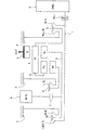
- FIG. 1 is a skeleton diagram illustrating an automatic transmission according to a first embodiment.
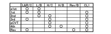
- a combination of a synchronous engagement with five engagement elements and a friction engagement with one friction element achieves a forward speed and a reverse speed of a stepped gear and a continuously variable speed.
- It is an engagement operation
- surface figure which shows a combined operation state.
- It is a skeleton figure which shows the torque flow in the 1st gear stage (e1st) in EV start mode.
- eCVT continuously variable speed stage
- FIG. 1 is a skeleton diagram illustrating an automatic transmission according to a first embodiment.
- the overall configuration of the automatic transmission according to the first embodiment will be described with reference to FIG.
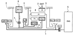
- the automatic transmission includes an input shaft 1 (input member), an output gear 2 (output member), a transmission case 3 (stationary part), and a Ravigneaux planetary gear set 4 ( Planetary gear set having four rotating elements).
- input clutch CL1, low and reverse clutch L & R / C first clutch
- high clutch H / C second clutch
- low brake L / B first brake
- a high brake H / B second brake
- a reverse brake Rev / B third brake
- the input shaft 1 can be connected to the engine 5 via an input clutch CL1.
- the input clutch CL1 is a dock clutch in which the other engagement / release elements are meshed and engaged (hereinafter referred to as “synchronized engagement”) in a rotationally synchronized state, while pressing the friction surface.
- synchronized engagement a dock clutch in which the other engagement / release elements are meshed and engaged (hereinafter referred to as “synchronized engagement”) in a rotationally synchronized state, while pressing the friction surface.
- a friction clutch that is friction-engaged is used.
- the output gear 2 meshes with the ring gear R of the Ravigneaux planetary gear set 4 and transmits the rotational driving force to driving wheels (not shown).
- the transmission case 3 is a case for storing the Ravigneaux planetary gear set 4 and the engagement / release element, and serves as a stationary portion when the low brake L / B, the high brake H / B, and the reverse brake Rev / B are synchronized. Fix it.
- the Ravigneaux type planetary gear set 4 is a planetary gear set having four rotating elements.
- the single pinion side sun gear Ss (first sun gear), the double pinion side sun gear Sd (second sun gear), and the short pinion gear Ps ( The first pinion gear), the long pinion gear Pl (second pinion gear), the ring gear R, and the carrier C are included.
- Single pinion side sun gear Ss and ring gear R mesh with long pinion gear Pl, respectively.
- the double pinion side sun gear Sd meshes with the short pinion gear Ps.
- the short pinion gear Ps and the long pinion gear Pl mesh with each other and are rotatably supported by a common carrier C.
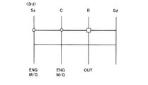
- the four rotating elements of the Ravigneaux type planetary gear set 4 are arranged in the order of arrangement on the common velocity diagram, the single pinion-side sun gear Ss (first element), the carrier C (second element), and the ring gear R (third element).
- the double pinion side sun gear Sd (fourth element) is used.
- each connection configuration of the first element (single pinion side sun gear Ss), the second element (carrier C), the third element (ring gear R), and the fourth element (double pinion side sun gear Sd) will be described. explain.
- the single pinion-side sun gear Ss is always connected to the motor / generator 6 via the connecting gear 7 or the like. And it is connectable with the input shaft 1 by the synchro engagement of the low & reverse clutch L & R / C. Furthermore, it can be fixed to the transmission case 3 by synchro engagement of the high brake H / B.
- the carrier C can be connected to the input shaft 1 by synchronizing the high clutch H / C. And it can fix to the transmission case 3 by the synchro engagement of reverse brake Rev / B.
- the ring gear R is always connected to the output gear 2.
- the double pinion side sun gear Sd can be fixed to the transmission case 3 by low brake L / B synchro engagement.
- the input shaft 1 is arranged on the inner periphery of the Ravigneaux type planetary gear set 4.
- the high clutch H / C and the reverse brake Rev / B are arranged on one side (engine 5 side) of the Ravigneaux planetary gear set 4 in the axial direction. More specifically, it is arranged at a position between the Ravigneaux type planetary gear set 4 and the input clutch CL1.
- the low brake L / B is disposed on the other side in the axial direction of the Ravigneaux planetary gear set 4.
- the low & reverse clutch L & R / C and the high brake H / B are on the other side in the axial direction of the Ravigneaux planetary gear set 4 and farther from the Ravigneaux planetary gear set 4 than the low brake L / B. Placed in.
- the motor / generator 6 is disposed at a position between the low brake L / B and the high brake H / B. This motor / generator 6 is always connected to the single pinion-side sun gear Ss via a connecting member 8 that passes between the inner peripheral side of the single pinion-side sun gear Ss and the outer peripheral side of the input shaft 1.
- the high clutch H / C and the reverse brake Rev / B are configured as a pair of dog clutches capable of selectively synchronizing the high clutch H / C and the reverse brake Rev / B. That is, the high clutch H / C is synchronized by sliding the common coupling sleeve 9 from the neutral position to the right in FIG. Further, the common brake sleeve 9 is slid in the left direction in FIG. 1 from the neutral position, whereby the reverse brake Rev / B is synchronized.
- the low & reverse clutch L & R / C and the high brake H / B are configured as a pair of dog clutches that can selectively engage the low & reverse clutch L & R / C and the high brake H / B. That is, the low & reverse clutch L & R / C is synchronized by sliding the common coupling sleeve 10 from the neutral position to the left in FIG. Further, the high brake H / B is synchronized by sliding the common coupling sleeve 10 from the neutral position to the right in FIG. Note that the low brake L / B is configured as a single dog clutch, and is synchronized by moving the coupling sleeve 11 to the right in FIG. 1 from the neutral position.
- FIG. 2 shows a stepped gear stage and a continuously variable speed stage with four forward speeds and one reverse speed with a combination of synchro engagement with five engagement elements and friction engagement with one friction element in the automatic transmission of the first embodiment.
- surface which achieves is shown.
- the engagement operation structure in each gear stage is demonstrated.
- the automatic transmission according to the first embodiment can be switched between the EV start mode and the continuously variable transmission mode.
- the continuously variable shift It has a continuously variable speed (eCVT), a fourth speed (4th), and a reverse speed (Rev) in the mode.
- the first shift stage (e1st) in the EV start mode is established by synchronizing the low brake L / B.
- the “EV start mode” refers to a mode in which the low brake L / B can be synchronized and the vehicle can run only with the driving force of the motor / generator 6.
- the low & reverse clutch L & R / C is synchro-engaged in advance in preparation for shifting to the first shift stage (1st).
- the first gear (1st) is established by synchronizing the low & reverse clutch L & R / C and the low brake L / B and frictionally engaging the input clutch CL1. That is, the first shift speed (1st) is different from the first shift speed (e1st) in the EV start mode in that the vehicle can run with a driving force that combines the engine 5 and the motor / generator 6.
- the second speed (2nd) is established by synchronizing the low brake L / B and the high clutch H / C and frictionally engaging the input clutch CL1.
- the gear ratio of the second gear stage (2nd) in which the engine rotational speed is the input rotational speed of the Ravigneaux planetary gear set 4 is smaller than the gear ratio of the first gear stage (1st).
- the third speed (3rd) is established by synchronizing the low & reverse clutch L & R / C and the high clutch H / C.
- the input clutch CL1 is frictionally engaged.
- the gear ratio of the third gear stage (3rd) in which the motor rotational speed or the engine rotational speed is the input rotational speed of the Ravigneaux planetary gear set 4 is 1.
- the gear ratio is 1, and the gear ratio of the second gear stage (2nd) Is also small.
- the continuously variable speed (eCVT) in the continuously variable speed mode is established by synchronizing the high clutch H / C and frictionally engaging the input clutch CL1.
- the power generation ratio of the motor / generator 6 can be controlled to change the gear ratio steplessly, and charging of the battery (not shown) while running with the driving force of the engine 5 is possible.
- a possible mode That is, when the power generation amount control of the motor / generator 6 is performed, a variable load is applied to the single pinion-side sun gear Ss of the Ravigneaux type planetary gear set 4 to which the motor / generator 6 is connected. As a result, the load received by the engine 5 is changed, and a continuously variable speed (eCVT) is obtained in which the gear ratio with the engine speed as the input speed is changed steplessly.
- the fourth speed (4th) is established by synchronizing the high clutch H / C and the high brake H / B and frictionally engaging the input clutch CL1.
- the gear ratio of the fourth gear stage (4th) in which the engine rotational speed is the input rotational speed of the Ravigneaux planetary gear set 4 is smaller than the gear ratio of the third gear stage (3rd) (overdrive gear stage).
- the reverse gear (Rev) is established by synchronizing the low & reverse clutch L & R / C and the reverse brake Rev / B. When there is an engine drive request, the input clutch CL1 is frictionally engaged.
- the reverse gear (Rev) uses the motor rotational speed or the engine rotational speed as the input rotational speed of the Ravigneaux planetary gear set 4 and reverses the rotational direction of the output gear 2 with respect to the forward gear.
- the common speed diagram as shown in FIG. 4 is drawn by the motor input rotation speed to the single pinion side sun gear Ss and the case fixing of the double pinion side sun gear Sd. For this reason, from the ring gear R of the Ravigneaux type planetary gear set 4, the gear ratio at the first gear stage (e1st) in which the motor input rotation speed to the single pinion side sun gear Ss is reduced is obtained.
- the EV start mode that can engage with the low brake L / B and start only with the driving force of the motor / generator 6 can start with good response while maintaining quietness. it can.
- the clutch changeover control of releasing the low brake L / B and engaging the high clutch H / C is used.
- the input clutch CL1 is engaged after the engine is started, it is possible to switch from the first gear (e1st) to the continuously variable gear (eCVT).
- the low & reverse clutch L & R / C is preset in the first gear (e1st) in the EV start mode. Are engaged. For this reason, the first shift stage (1st) that applies the engine drive force to the motor drive force from the first shift stage (e1st) with only the motor drive force with good response just by engaging the input clutch CL1 after the engine 5 is started. Can be transferred to.
- the clutch change control that engages the low & reverse clutch L & R / C and releases the high clutch H / C. , It is possible to shift to the first gear (1st). Further, by controlling the torque of the motor together with this clutch changeover control, a smooth shift without running out of torque is possible even with a dog clutch.
- the assist traveling mode (motor power running: FIG. 5), engine traveling mode (no motor load), and engine power generation traveling mode (generator regeneration)
- Any mode can be selected to travel. That is, the engine load can be controlled by selecting the travel mode.
- the common speed diagram as shown in FIG. 8 is drawn by the engine input rotation speed to the carrier C and the case fixing of the double pinion side sun gear Sd. For this reason, from the ring gear R of the Ravigneaux planetary gear set 4, the gear ratio at the second speed (2nd) in which the engine input rotational speed to the carrier C is reduced can be obtained. Note that the gear ratio at the second gear (2nd) is smaller than the gear ratio at the first gear (1st) (high gear ratio side).
- the clutch change control that releases the low & reverse clutch L & R / C and engages the low brake L / B , It is possible to shift to the second gear (2nd). Further, by controlling the torque of the motor together with this clutch changeover control, a smooth shift without running out of torque is possible even with a dog clutch.
- any mode can be selected to travel. That is, the engine load that the engine 5 receives from the motor / generator 6 can be controlled by selecting the travel mode.
- the rotational speed of the motor / generator 6 connected to the single pinion-side sun gear Ss is faster than the engine input rotational speed to the carrier C, as shown in FIG.
- the clutch changeover control that engages the low & reverse clutch L & R / C and releases the high brake H / B. , It is possible to shift to the third gear (3rd). Further, by controlling the torque of the motor together with this clutch changeover control, a smooth shift without running out of torque is possible even with a dog clutch.
- one of assist driving mode (motor power running), engine driving mode (no motor load), and engine power generation driving mode (generator regeneration) It is possible to drive by selecting the mode. That is, the engine load can be controlled by selecting the travel mode.
- the common speed diagram as shown in FIG. 12 is drawn by the engine input rotation speed to the carrier C and the variable load to the single pinion side sun gear Ss. For this reason, from the ring gear R of the Ravigneaux planetary gear set 4, the gear ratio ranges from the gear ratio at which the engine input rotation speed to the carrier C is reduced to the gear ratio at which the engine input rotation speed to the carrier C is increased.
- a continuously variable transmission ratio capable of changing the transmission ratio is obtained. For example, when the output rotation speed (vehicle speed) is constant, the rotation speed of the motor / generator 6 decreases as the power generation load increases, and the speed-up side gear ratio is obtained.
- the continuously variable transmission ratio can be obtained by controlling the power generation amount of the motor / generator 6.
- the power ratio of the motor / generator 6 can be controlled to change the gear ratio steplessly, and the driving force of the engine 5 can be changed.
- the battery which is not shown in the figure can be charged while traveling.
- the second gear (2nd), the third gear stage (3rd), and the fourth gear stage (4th) can be responsive by simply engaging the engaging elements while the rotational speeds of the engaging elements to be engaged are synchronized. It is possible to shift to any gear.
- the common speed diagram as shown in FIG. 14 is drawn by the engine input rotation speed to the carrier C and the case fixing of the single pinion side sun gear Ss. For this reason, the overdrive speed ratio at the fourth speed (4th) in which the engine input rotational speed to the carrier C is increased is obtained from the ring gear R of the Ravigneaux planetary gear set 4.
- the vehicle can travel backward using at least one of the engine 5 and the motor / generator 6.
- any of assist reverse mode (motor power running), engine reverse mode (motor load zero), and engine power generation reverse mode (generator regeneration) You can select a mode and move backward. That is, the engine load can be controlled by selecting the reverse mode.
- the automatic transmission according to the first embodiment can obtain each stepped gear (e1st, 1st, 2nd, 3rd, 4th, Rev) and continuously variable gear (eCVT).
- eCVT continuously variable gear
- a Ravigneaux type planetary gear set 4 having four rotating elements, two clutches (L & R / C, H / C) and one brake (L / B) are used, so that the first gear ( 1st), 2nd speed (2nd), 3rd speed (3rd), and continuously variable speed (eCVT).
- the carrier C of the Ravigneaux type planetary gear set 4 and the engine 5 are connected by engaging the high clutch H / C.
- the motor / generator 6 can change the variable load of the single pinion sun gear Ss of the Ravinio planetary gear set 4.
- a target regenerative torque that keeps the engine power generation load below the predetermined load is set, and the torque control that matches the regenerative torque of the motor / generator 6 with the target regenerative torque.
- a target motor rotational speed that maintains the engine rotational speed at the fuel-efficient speed is set, and the rotational speed of the motor / generator 6 matches the target motor rotational speed.
- the fourth shift stage (4th) using the rotational driving force from the engine 5 is obtained.
- the configuration was established. With this configuration, when the fourth shift stage (4th) is set during high-speed traveling, the rotational speed of the engine 5 changes in a rotational speed region where engine efficiency is high. Therefore, during high-speed traveling, it is possible to travel only by the engine 5 that rotates in a rotational speed region where engine efficiency is high without using the motor / generator 6.
- Example 1 the reverse brake Rev / B is added, and the reverse shift stage (Rev) is established by engaging the low & reverse clutch L & R / C and the reverse brake Rev / B.
- the vehicle can travel backward by the rotational driving force of the engine 5 alone.
- the planetary gear set having four rotating elements is a Ravigneaux type planetary gear set 4, the input shaft 1 is arranged on the inner periphery of the Ravinio type planetary gear set 4, and the high clutch H / C and the reverse brake Rev. / B is arranged on one side in the axial direction of the Ravigneaux type planetary gear set 4.
- the low brake L / B is arranged on the other side in the axial direction of the Ravinio type planetary gear set 4, and the low & reverse clutch L & R / C and the high brake H / B are arranged on the other side in the axial direction of the Ravinio type planetary gear set 4.
- the motor / generator 6 has a layout configuration in which the motor / generator 6 is disposed at a position between the low brake L / B and the high brake H / B. With this layout configuration, the axial dimension of the Ravigneaux planetary gear set 4 is shortened compared to the case where two planetary gear sets are used.
- the plurality of engagement / release elements are arranged separately on one side and the other side in the axial direction with the Ravigneaux planetary gear set 4 interposed therebetween, thereby reducing the axial dimension of the plurality of engagement / release elements. .
- the motor / generator 6 can be set in the transmission case 3 by disposing the motor / generator 6 in the gap positions of the plurality of engagement / release elements. Therefore, it can be set as the compact automatic transmission which shortened the axial direction dimension.
- the high clutch H / C and the reverse brake Rev / B are configured as a pair of dog clutches that can be selectively synchronized, and the low & reverse clutch L & R / C and the high brake H / B are selectively selected.
- a pair of dog clutches capable of synchro-engagement was constructed. That is, the high clutch H / C and the reverse brake Rev / B are engaging / disengaging elements that are not simultaneously engaged in one shift stage, as is apparent from FIG. As is apparent from FIG. 2, the low & reverse clutch L & R / C and the high brake H / B are also engaging / disengaging elements that are not simultaneously engaged in one shift stage. Therefore, by arranging the engagement / release elements that are not simultaneously engaged, a compact automatic transmission with a further reduced axial dimension can be obtained. In addition, it is possible to reduce the number of parts by sharing the coupling sleeves 9 and 10 and the speed change actuator.
- an automatic transmission capable of switching between an EV start mode and a continuously variable transmission mode is used.
- the first shift stage (e1st) in the EV start mode is engaged with a low brake L / B, and a motor / generator. It is set as the mode which can drive
- the continuously variable transmission mode eCVT
- the gear ratio can be changed steplessly by engaging only the high clutch H / C and controlling the power generation amount of the motor / generator 6.
- the battery can be charged while traveling with a driving force of 5.
- EV traveling with only the motor / generator 6 is possible.
- the continuously variable transmission mode it is possible to run the HEV and charge the battery at an operating point with good engine efficiency. Therefore, it is possible to obtain an automatic transmission that saves fuel and saves fuel.
- the second element (carrier C) can be connected to the input member (input shaft 1) by engagement of a second clutch (high clutch H / C); Always connecting the third element (ring gear R) to the output member (output gear 2);
- the fourth element (double pinion side sun gear Sd) can be fixed to the stationary part (transmission case 3) by engagement of a first brake (low brake L / B), By engaging the first clutch (low & reverse clutch L & R / C) and the first brake (low brake L / B), the first gear (1st) is established, By engaging the first brake (low brake L / B) and the second clutch (high clutch H / C), a second gear (2nd gear ratio) having a smaller gear ratio than the first gear (1st).
- the first element (single pinion side sun gear Ss) can be fixed to the stationary part (transmission case 3) by engagement of a second brake (high brake H / B), and the second clutch (high clutch H / C) and the second brake (high brake H / B) are engaged to establish a fourth gear (4th) with a smaller gear ratio than the third gear (3rd) (FIG. 13). , FIG. 14).
- a second brake high brake H / B
- the second clutch high clutch H / C
- the second brake high brake H / B
- the second element (carrier C) can be fixed to the stationary part (transmission case 3) by engagement of a third brake (reverse brake Rev / B).
- a reverse gear (Rev) is established by engaging the first clutch (low & reverse clutch L & R / C) and the third brake (reverse brake Rev / B) (FIGS. 15 and 16).
- the second brake (high brake H / B) can be fixed to the stationary part (transmission case 3),
- the carrier C can be connected to the input member (input shaft 1) by engagement of a second clutch (high clutch H / C), and the stationary portion (by a third brake (reverse brake Rev / B)) It can be fixed to the transmission case 3)
- the ring gear R is always connected to an output member (output gear 2)
- the second sun gear (double pinion side sun gear Sd) can be fixed to the stationary part (transmission case 3) by engagement of the first brake (low brake L / B), By engaging the first clutch (low & reverse clutch L & R / C) and the first brake (low brake L / B), the first gear (1st) is established, By engaging the first brake (low brake L / B) and the second clutch (high clutch H / C), a second gear (2nd gear ratio) having a smaller gear ratio than the first gear (1st).
- the input member (input shaft 1) is disposed on the inner periphery of the Ravigneaux planetary gear set 4,
- the second clutch (high clutch H / C) and the third brake (reverse brake Rev / B) are arranged on one side in the axial direction of the Ravigneaux type planetary gear set 4,
- the first brake (low brake L / B) is disposed on the other axial side of the Ravigneaux planetary gear set 4;
- the first clutch (low & reverse clutch L & R / C) and the second brake (high brake H / B) are on the other side in the axial direction of the Ravigneaux type planetary gear set 4 and the first brake It is arranged on the side farther from the Ravinio type planetary gear set 4 than (low brake L / B),
- the motor / generator 6 is provided between the first brake (low brake L / B) and the second brake (high brake H / B), and on the inner peripheral side of the second sun gear (double pinion side sun gear Sd).
- the second clutch (high clutch H / C) and the third brake (reverse brake Rev / B) are the second clutch (high clutch H / C) and the third brake (reverse brake Rev / B). Is configured as a pair of dog clutches that can be selectively engaged,
- the first clutch (low & reverse clutch L & R / C) and the second brake (high brake H / B) are the first clutch (low & reverse clutch L & R / C) and second brake (high brake H / B).
- the automatic transmission can switch between EV start mode and continuously variable transmission mode
- the EV start mode is a mode in which the first brake (low brake L / B) is engaged and the vehicle can run only with the driving force of the motor / generator 6.
- the continuously variable transmission mode only the second clutch (high clutch H / C) is engaged, and the power generation amount of the motor / generator 6 can be controlled to change the gear ratio steplessly.
- the battery can be charged while traveling with the driving force (FIGS. 3, 4, 11, and 12). Therefore, in addition to the effects (1) to (5), it is possible to obtain an automatic transmission that saves fuel and saves fuel consumption.
- Example 1 Although the automatic transmission of this invention has been demonstrated based on Example 1, it is not restricted to this Example 1 about a concrete structure, The summary of the invention which concerns on each claim of a claim As long as they do not deviate, design changes and additions are permitted.
- Example 1 as a planetary gear set having four rotating elements, a Rabinio type planetary gear set in which a carrier and a ring gear of a single pinion planet and a double pinion planet are connected to each other is shown.
- the planetary gear set having four rotating elements is not limited to this, and two planetary gear sets are used, and any two rotating elements are connected to each other to have four rotating elements.
- a planetary gear set may be used.
- the motor / generator 6 is connected to the connecting member 8 via the connecting gear 7 .
- the motor / generator may be an example in which the motor / generator is set in the transmission case by fixing the rotor to the connecting member and fixing the stator to the transmission case.
- Example 1 an example in which a dog clutch by synchro engagement is used as an engagement / release element except for the input clutch CL1 is shown.
- the engagement / release element may be an example using a friction clutch or a friction brake by friction engagement.
- the automatic transmission As an automatic transmission, an example is shown in which a stepped gear stage and a continuously variable speed stage with four forward speeds and one reverse speed are achieved.
- the automatic transmission may be an example in which a stepped gear stage and a continuously variable speed stage of three forward speeds and one reverse speed are achieved.
- the high brake H / B can be omitted.
Abstract
Description
この自動変速機であって、前記遊星歯車組の4つの回転要素を、共通速度線図上における並び順に第1要素、第2要素、第3要素、第4要素、とする。
前記第1要素を、モータ/ジェネレータに常時連結するとともに、第1クラッチの係合により前記入力部材に連結可能とする。
前記第2要素を、第2クラッチの係合により前記入力部材に連結可能とする。
前記第3要素を、出力部材に常時連結する。
前記第4要素を、第1ブレーキの係合により前記静止部に固定可能とする。
前記第1クラッチと前記第1ブレーキとを係合することによって第1変速段が成立する。
前記第1ブレーキと前記第2クラッチとを係合することによって前記第1変速段よりも小さい変速比の第2変速段が成立する。
前記第1クラッチと前記第2クラッチとを係合することによって前記第2変速段よりも小さい変速比の第3変速段が成立する。
前記第2クラッチを係合し、前記モータ/ジェネレータの回転速度を変更することによって変速比を無段階に変更可能な無段変速段が成立する。 In order to achieve the above object, the present invention includes an input member connectable to the engine, an output member, a stationary portion, and a planetary gear set having four rotating elements.
In this automatic transmission, the four rotating elements of the planetary gear set are a first element, a second element, a third element, and a fourth element in the order of arrangement on the common speed diagram.
The first element is always connected to the motor / generator and can be connected to the input member by engagement of the first clutch.
The second element is connectable to the input member by engagement of a second clutch.
The third element is always connected to the output member.
The fourth element can be fixed to the stationary portion by engagement of the first brake.
A first shift stage is established by engaging the first clutch and the first brake.
By engaging the first brake and the second clutch, a second gear having a smaller gear ratio than the first gear is established.
By engaging the first clutch and the second clutch, a third shift stage having a smaller gear ratio than the second shift stage is established.
By engaging the second clutch and changing the rotational speed of the motor / generator, a continuously variable speed stage is established in which the speed ratio can be changed steplessly.
この無段変速段の選択時においては、第2クラッチを係合することによって遊星歯車組の第2要素とエンジンが連結される。したがって、遊星歯車組の第1要素に常時連結されるモータ/ジェネレータの発電量を制御すると、モータ/ジェネレータが遊星歯車組の第1要素の可変負荷となり、第2要素に連結されるエンジンの回転速度(=入力回転速度)が負荷拘束の程度に応じて無段階に変更される。つまり、入力と出力の回転速度比率である変速比を無段階に変更することができる。これとともに、モータ/ジェネレータによる発電量(回生トルク)を変更することで、モータ/ジェネレータによりエンジン回転速度とエンジン負荷(=発電負荷)をコントロールすることができる。
この結果、モータ/ジェネレータによりエンジンの負荷および回転速度をコントロールすることで、エンジン動作点の自由度を大きくすることができる。 Therefore, in addition to the stepped gears from the first gear to the third gear, the continuously variable gear is established.
At the time of selecting the continuously variable speed, the second element of the planetary gear set and the engine are connected by engaging the second clutch. Therefore, when the power generation amount of the motor / generator always connected to the first element of the planetary gear set is controlled, the motor / generator becomes a variable load of the first element of the planetary gear set, and the rotation of the engine connected to the second element The speed (= input rotation speed) is changed steplessly according to the degree of load constraint. That is, it is possible to change the speed ratio, which is the ratio between the input and output rotational speeds, without any steps. At the same time, by changing the power generation amount (regenerative torque) by the motor / generator, the engine speed and the engine load (= power generation load) can be controlled by the motor / generator.
As a result, the degree of freedom of the engine operating point can be increased by controlling the engine load and rotation speed with the motor / generator.
ハイブリッド車両に搭載される実施例1の自動変速機における構成を、「全体構成」、「各変速段での係合作動構成」に分けて説明する。 First, the configuration will be described.
The configuration of the automatic transmission according to the first embodiment that is mounted on a hybrid vehicle will be described separately as “overall configuration” and “engagement operation configuration at each shift stage”.
図1は、実施例1の自動変速機を示すスケルトン図である。以下、図1に基づいて、実施例1の自動変速機の全体構成を説明する。 [overall structure]
FIG. 1 is a skeleton diagram illustrating an automatic transmission according to a first embodiment. Hereinafter, the overall configuration of the automatic transmission according to the first embodiment will be described with reference to FIG.
ここで、入力クラッチCL1は、他の係合/解放要素が、回転同期状態で噛み合い係合(以下、「シンクロ係合」という。)されるドククラッチであるのに対し、摩擦面を押し付けることにより摩擦係合される摩擦クラッチを用いている。 The
Here, the input clutch CL1 is a dock clutch in which the other engagement / release elements are meshed and engaged (hereinafter referred to as “synchronized engagement”) in a rotationally synchronized state, while pressing the friction surface. A friction clutch that is friction-engaged is used.
なお、ローブレーキL/Bは、単独のドグクラッチと構成されていて、ニュートラル位置からカップリングスリーブ11を図1の右方向にスライド移動させることでシンクロ係合される。 The low & reverse clutch L & R / C and the high brake H / B are configured as a pair of dog clutches that can selectively engage the low & reverse clutch L & R / C and the high brake H / B. That is, the low & reverse clutch L & R / C is synchronized by sliding the
Note that the low brake L / B is configured as a single dog clutch, and is synchronized by moving the
図2は、実施例1の自動変速機において5つの係合要素によるシンクロ係合と1つの摩擦要素による摩擦係合の組み合わせにより前進4速・後退1速の有段変速段と無段変速段を達成する係合作動表を示す。以下、図2に基づき、各変速段での係合作動構成を説明する。 [Engagement configuration at each gear position]
FIG. 2 shows a stepped gear stage and a continuously variable speed stage with four forward speeds and one reverse speed with a combination of synchro engagement with five engagement elements and friction engagement with one friction element in the automatic transmission of the first embodiment. The engagement operation | movement table | surface which achieves is shown. Hereinafter, based on FIG. 2, the engagement operation structure in each gear stage is demonstrated.
これによりエンジン5が受ける負荷が変更され、エンジン回転速度を入力回転速度とする変速比が無段階に変更される無段変速段(eCVT)が得られる。 The continuously variable speed (eCVT) in the continuously variable speed mode is established by synchronizing the high clutch H / C and frictionally engaging the input clutch CL1. In this “continuously variable transmission mode”, the power generation ratio of the motor /
As a result, the load received by the
実施例1の自動変速機における作用を、「各変速段での変速作用」、「各請求項に対応する作用」に分けて説明する。 Next, the operation will be described.
The operation of the automatic transmission according to the first embodiment will be described by dividing it into “shift operation at each gear stage” and “operation corresponding to each claim”.
(EV発進モードでの第1変速段)
EV発進モードでの第1変速段(e1st)での変速作用を、図3及び図4に基づき説明する。EV発進モードでの第1変速段(e1st)においては、ローブレーキL/Bを係合することによって、ラビニオ型遊星歯車組4のダブルピニオン側サンギアSdがトランスミッションケース3に固定される。この状態でモータ/ジェネレータ6からの回転駆動力が、連結ギア7及び連結メンバ8を介してシングルピニオン側サンギアSsに入力される(図3の矢印)。 [Shifting action at each gear stage]
(First gear in EV start mode)
The speed change operation at the first speed (e1st) in the EV start mode will be described with reference to FIGS. In the first gear position (e1st) in the EV start mode, the double pinion side sun gear Sd of the Ravigneaux type planetary gear set 4 is fixed to the
第1変速段(1st)での変速作用を、図5及び図6に基づき説明する。
第1変速段(1st)においては、ローブレーキL/Bを係合することによって、ラビニオ型遊星歯車組4のダブルピニオン側サンギアSdがトランスミッションケース3に固定される。
また、ロー&リバースクラッチL&R/Cと入力クラッチCL1を係合することによって、エンジン5がラビニオ型遊星歯車組4のシングルピニオン側サンギアSsに連結される。この状態でエンジン5からの回転駆動力が、入力クラッチCL1→入力軸1→ロー&リバースクラッチL&R/C→連結メンバ8を介してシングルピニオン側サンギアSsに入力される。アシスト走行モードの選択時には、トルク制御によるモータ/ジェネレータ6からの駆動力が、連結ギア7及び連結メンバ8を介してシングルピニオン側サンギアSsに入力される(図5の矢印)。 (First gear)
The speed change operation at the first speed (1st) will be described with reference to FIGS.
At the first speed (1st), the double pinion-side sun gear Sd of the Ravigneaux planetary gear set 4 is fixed to the
Further, by engaging the low & reverse clutch L & R / C and the input clutch CL1, the
第2変速段(2nd)での変速作用を、図7及び図8に基づき説明する。
第2変速段(2nd)では、ローブレーキL/Bを係合することによって、ラビニオ型遊星歯車組4のダブルピニオン側サンギアSdがトランスミッションケース3に固定される。また、ハイクラッチH/Cと入力クラッチCL1を係合することによって、エンジン5がラビニオ型遊星歯車組4のキャリアCに連結される。そして、エンジン5からの回転駆動力が、入力クラッチCL1及びハイクラッチH/Cを介してキャリアCに入力される(図7の矢印)。 (2nd gear)
The speed change action at the second speed (2nd) will be described with reference to FIGS.
At the second gear position (2nd), the double pinion side sun gear Sd of the Ravigneaux planetary gear set 4 is fixed to the
第3変速段(3rd)での変速作用を、図9及び図10に基づき説明する。第3変速段(3rd)においては、ロー&リバースクラッチL&R/CとハイクラッチH/Cを係合することによって、ラビニオ型遊星歯車組4のシングルピニオン側サンギアSsとキャリアCが連結される。つまり、ラビニオ型遊星歯車組4の4つの回転要素が一体に回転する状態となる。したがって、EVモード選択時には、モータ/ジェネレータ6からの回転駆動力が、シングルピニオン側サンギアSsとキャリアCに入力される。また、HEVモード時には、エンジン5を始動した後、入力クラッチCL1を係合することで、エンジン5とモータ/ジェネレータ6からの回転駆動力が、シングルピニオン側サンギアSsとキャリアCに入力される(図9)。 (3rd gear)
The speed change operation at the third speed (3rd) will be described with reference to FIGS. At the third speed (3rd), the single pinion side sun gear Ss of the Ravigneaux type planetary gear set 4 and the carrier C are connected by engaging the low & reverse clutch L & R / C and the high clutch H / C. That is, the four rotating elements of the Ravigneaux type planetary gear set 4 are rotated together. Accordingly, when the EV mode is selected, the rotational driving force from the motor /
無段変速モードでの無段変速段(eCVT)での変速作用を、図11及び図12に基づき説明する。
無段変速モードでの無段変速段(eCVT)においては、ハイクラッチH/Cと入力クラッチCL1を係合することによって、エンジン5がラビニオ型遊星歯車組4のキャリアCに連結される。この状態でエンジン5からの回転駆動力が、入力クラッチCL1及びハイクラッチH/Cを介してキャリアCに入力される(図11の矢印)。そして、モータ/ジェネレータ6の発電量制御が行われると、モータ/ジェネレータ6が連結されるラビニオ型遊星歯車組4のシングルピニオン側サンギアSsに対し可変負荷(発電量大ほど負荷拘束の程度が大)が与えられる。 (Continuously variable speed in continuously variable speed mode)
The speed change operation at the continuously variable speed (eCVT) in the continuously variable speed mode will be described with reference to FIGS.
In the continuously variable transmission (eCVT) in the continuously variable transmission mode, the
第4変速段(4th)での変速作用を、図13及び図14に基づき説明する。
第4変速段(4th)においては、ハイブレーキH/Bを係合することによって、ラビニオ型遊星歯車組4のシングルピニオン側サンギアSsとモータ/ジェネレータ6がトランスミッションケース3に固定される。そして、ハイクラッチH/Cと入力クラッチCL1を係合することによって、エンジン5がラビニオ型遊星歯車組4のキャリアCに連結される。この状態でエンジン5からの回転駆動力が、入力クラッチCL1及びハイクラッチH/Cを介してキャリアCに入力される(図13の矢印)。 (4th gear)
The speed change operation at the fourth speed (4th) will be described with reference to FIGS.
At the fourth speed (4th), the single pinion side sun gear Ss and the motor /
前記後退変速段(Rev)での変速作用を、図15及び図16に基づき説明する。
後退変速段(Rev)においては、リバースブレーキRev/Bを係合することによって、ラビニオ型遊星歯車組4のキャリアCがトランスミッションケース3に固定される。そして、ロー&リバースクラッチL&R/Cと入力クラッチCL1を係合することによって、エンジン5とモータ/ジェネレータ6が、ラビニオ型遊星歯車組4のシングルピニオン側サンギアSsに連結される。この状態でエンジン5からの回転駆動力が、入力クラッチCL1→入力軸1→ロー&リバースクラッチL&R/C→連結メンバ8を介してシングルピニオン側サンギアSsに入力される。モータ/ジェネレータ6からの駆動力が、連結ギア7及び連結メンバ8を介してシングルピニオン側サンギアSsに入力される(図15の矢印)。 (Reverse gear)
The speed change operation at the reverse speed (Rev) will be described with reference to FIGS. 15 and 16.
At the reverse shift speed (Rev), the carrier C of the Ravigneaux planetary gear set 4 is fixed to the
実施例1の自動変速機は、上記のように、各有段変速段(e1st,1st,2nd,3rd,4th,Rev)と無段変速段(eCVT)を得ることができる。以下、実施例1の自動変速機の特徴を反映する各請求項に対応する作用を説明する。 [Action corresponding to each claim]
As described above, the automatic transmission according to the first embodiment can obtain each stepped gear (e1st, 1st, 2nd, 3rd, 4th, Rev) and continuously variable gear (eCVT). The operation corresponding to each claim reflecting the characteristics of the automatic transmission according to the first embodiment will be described below.
この構成により、無段変速段(eCVT)の選択時においては、ハイクラッチH/Cを係合することによってラビニオ型遊星歯車組4のキャリアCとエンジン5が連結される。したがって、ラビニオ型遊星歯車組4のシングルピニオン側サンギアSsに常時連結されるモータ/ジェネレータ6の発電量を制御すると、モータ/ジェネレータ6がラビニオ型遊星歯車組4のシングルピニオン側サンギアSsの可変負荷となり、キャリアCに連結されるエンジン5の回転速度(=入力回転速度)が負荷拘束の程度に応じて無段階に変更される。つまり、入力と出力の回転速度比率である変速比を無段階に変更することができる。これとともに、モータ/ジェネレータ6による発電量(回生トルク)を変更することで、モータ/ジェネレータ6によりエンジン回転速度とエンジン負荷(=発電負荷)をコントロールすることができる。
例えば、エンジン5が受ける発電負荷を所定負荷以下に保ちたいときは、エンジン発電負荷を所定負荷以下に保つ目標回生トルクを設定し、モータ/ジェネレータ6の回生トルクを目標回生トルクに一致させるトルク制御を行う。また、エンジン5の回転速度を省燃費速度に保ちたいときは、エンジン回転速度を省燃費速度に保つ目標モータ回転速度を設定し、モータ/ジェネレータ6の回転速度を目標モータ回転速度に一致させる回転数制御を行う。何れのエンジン動作点を目指す場合も、モータ/ジェネレータ6の発電量制御により実現される無段変速による自由度によって許容される。この結果、モータ/ジェネレータ6によりエンジン5の負荷および回転速度をコントロールすることで、エンジン動作点の自由度を大きくすることができる。 In the first embodiment, a Ravigneaux type planetary gear set 4 having four rotating elements, two clutches (L & R / C, H / C) and one brake (L / B) are used, so that the first gear ( 1st), 2nd speed (2nd), 3rd speed (3rd), and continuously variable speed (eCVT).
With this configuration, when the continuously variable speed stage (eCVT) is selected, the carrier C of the Ravigneaux type planetary gear set 4 and the
For example, when it is desired to keep the power generation load received by the
この構成により、高速走行時に第4変速段(4th)とすると、エンジン5の回転速度が、エンジン効率が高い回転速度領域を推移する。したがって、高速走行時において、モータ/ジェネレータ6を使用せずに、エンジン効率が高い回転速度領域で回転するエンジン5のみによる走行が可能になる。 In the first embodiment, by adding the high brake H / B and engaging the high clutch H / C and the high brake H / B, the fourth shift stage (4th) using the rotational driving force from the
With this configuration, when the fourth shift stage (4th) is set during high-speed traveling, the rotational speed of the
このレイアウト構成により、ラビニオ型遊星歯車組4による軸方向寸法が、2つの遊星歯車組を用いた場合に比べて短縮される。そして、複数の係合/解放要素がラビニオ型遊星歯車組4を挟んで軸方向の一方側と他方側に分けて配置することで、複数の係合/解放要素による軸方向寸法が短縮される。さらに、モータ/ジェネレータ6を複数の係合/解放要素の隙間位置に配置することで、トランスミッションケース3にモータ/ジェネレータ6を設定することができる。
したがって、軸方向寸法を短縮したコンパクトな自動変速機とすることができる。 In the first embodiment, the planetary gear set having four rotating elements is a Ravigneaux type planetary gear set 4, the
With this layout configuration, the axial dimension of the Ravigneaux planetary gear set 4 is shortened compared to the case where two planetary gear sets are used. The plurality of engagement / release elements are arranged separately on one side and the other side in the axial direction with the Ravigneaux planetary gear set 4 interposed therebetween, thereby reducing the axial dimension of the plurality of engagement / release elements. . Furthermore, the motor /
Therefore, it can be set as the compact automatic transmission which shortened the axial direction dimension.
すなわち、ハイクラッチH/CとリバースブレーキRev/Bは、図2から明らかなように、1つの変速段で同時に係合されることのない係合/解放要素である。ロー&リバースクラッチL&R/CとハイブレーキH/Bについても、図2から明らかなように、1つの変速段で同時に係合されることのない係合/解放要素である。
したがって、同時に係合されることのない係合/解放要素を隣接して配置することで、さらに軸方向寸法が短縮されたコンパクトな自動変速機にすることができる。加えて、カップリングスリーブ9,10や変速アクチュエータを共用することで、部品点数の削減を図ることができる。 In the first embodiment, the high clutch H / C and the reverse brake Rev / B are configured as a pair of dog clutches that can be selectively synchronized, and the low & reverse clutch L & R / C and the high brake H / B are selectively selected. A pair of dog clutches capable of synchro-engagement was constructed.
That is, the high clutch H / C and the reverse brake Rev / B are engaging / disengaging elements that are not simultaneously engaged in one shift stage, as is apparent from FIG. As is apparent from FIG. 2, the low & reverse clutch L & R / C and the high brake H / B are also engaging / disengaging elements that are not simultaneously engaged in one shift stage.
Therefore, by arranging the engagement / release elements that are not simultaneously engaged, a compact automatic transmission with a further reduced axial dimension can be obtained. In addition, it is possible to reduce the number of parts by sharing the
したがって、燃料消費量を抑えた省燃費による自動変速機を得ることができる。 In the first embodiment, an automatic transmission capable of switching between an EV start mode and a continuously variable transmission mode is used. The first shift stage (e1st) in the EV start mode is engaged with a low brake L / B, and a motor / generator. It is set as the mode which can drive | work only with 6 driving force. In the continuously variable transmission mode (eCVT), the gear ratio can be changed steplessly by engaging only the high clutch H / C and controlling the power generation amount of the motor /
Therefore, it is possible to obtain an automatic transmission that saves fuel and saves fuel.
実施例1の自動変速機にあっては、下記に列挙する効果を得ることができる。 Next, the effect will be described.
In the automatic transmission of the first embodiment, the effects listed below can be obtained.
出力部材(出力ギア2)と、
静止部(トランスミッションケース3)と、
4つの回転要素を有する遊星歯車組(ラビニオ型遊星歯車組4)と、を備える自動変速機であって、
前記遊星歯車組(ラビニオ型遊星歯車組4)の4つの回転要素を、共通速度線図上における並び順に第1要素(シングルピニオン側サンギアSs)、第2要素(キャリアC)、第3要素(リングギアR)、第4要素(ダブルピニオン側サンギアSd)、とし、
前記第1要素(シングルピニオン側サンギアSs)を、モータ/ジェネレータ6に常時連結するとともに、第1クラッチ(ロー&リバースクラッチL&R/C)の係合により前記入力部材(入力軸1)に連結可能とし、
前記第2要素(キャリアC)を、第2クラッチ(ハイクラッチH/C)の係合により前記入力部材(入力軸1)に連結可能とし、
前記第3要素(リングギアR)を、出力部材(出力ギア2)に常時連結し、
前記第4要素(ダブルピニオン側サンギアSd)を、第1ブレーキ(ローブレーキL/B)の係合により前記静止部(トランスミッションケース3)に固定可能とし、
前記第1クラッチ(ロー&リバースクラッチL&R/C)と前記第1ブレーキ(ローブレーキL/B)とを係合することによって第1変速段(1st)が成立し、
前記第1ブレーキ(ローブレーキL/B)と前記第2クラッチ(ハイクラッチH/C)とを係合することによって前記第1変速段(1st)よりも小さい変速比の第2変速段(2nd)が成立し、
前記第1クラッチ(ロー&リバースクラッチL&R/C)と前記第2クラッチ(ハイクラッチH/C)とを係合することによって前記第2変速段(2nd)よりも小さい変速比の第3変速段(3rd)が成立し、
前記第2クラッチ(ハイクラッチH/C)を係合し、前記モータ/ジェネレータ6の回転速度を変更することによって変速比を無段階に変更可能な無段変速段(eCVT)が成立する(図1)。
このため、モータ/ジェネレータ6によりエンジン5の負荷および回転速度をコントロールすることで、エンジン動作点の自由度を大きくすることができる。 (1) An input member (input shaft 1) connectable to the
An output member (output gear 2);
A stationary part (transmission case 3);
An automatic transmission comprising a planetary gear set (Ravinio type planetary gear set 4) having four rotating elements,
The four rotating elements of the planetary gear set (Ravinio type planetary gear set 4) are arranged in the order of arrangement on the common velocity diagram, the first element (single pinion side sun gear Ss), the second element (carrier C), the third element ( Ring gear R), fourth element (double pinion side sun gear Sd),
The first element (single pinion side sun gear Ss) is always connected to the motor /
The second element (carrier C) can be connected to the input member (input shaft 1) by engagement of a second clutch (high clutch H / C);
Always connecting the third element (ring gear R) to the output member (output gear 2);
The fourth element (double pinion side sun gear Sd) can be fixed to the stationary part (transmission case 3) by engagement of a first brake (low brake L / B),
By engaging the first clutch (low & reverse clutch L & R / C) and the first brake (low brake L / B), the first gear (1st) is established,
By engaging the first brake (low brake L / B) and the second clutch (high clutch H / C), a second gear (2nd gear ratio) having a smaller gear ratio than the first gear (1st). )
By engaging the first clutch (low & reverse clutch L & R / C) and the second clutch (high clutch H / C), a third gear stage having a smaller gear ratio than the second gear stage (2nd). (3rd) is established,
By engaging the second clutch (high clutch H / C) and changing the rotational speed of the motor /
For this reason, by controlling the load and rotation speed of the
このため、(1)の効果に加え、高速走行時において、モータ/ジェネレータ6を使用せずに、エンジン効率が高い回転速度領域で回転するエンジン5のみによる走行を行うことができる。 (2) The first element (single pinion side sun gear Ss) can be fixed to the stationary part (transmission case 3) by engagement of a second brake (high brake H / B), and the second clutch (high clutch H / C) and the second brake (high brake H / B) are engaged to establish a fourth gear (4th) with a smaller gear ratio than the third gear (3rd) (FIG. 13). , FIG. 14).
For this reason, in addition to the effect of (1), at the time of high speed traveling, it is possible to travel only by the
前記第1クラッチ(ロー&リバースクラッチL&R/C)と前記第3ブレーキ(リバースブレーキRev/B)とを係合することによって後退変速段(Rev)が成立する(図15、図16)。
このため、(1)又は(2)の効果に加え、バッテリ残量が少なく、モータ/ジェネレータ6のみの使用では走行できない場合であっても、エンジン5のみの回転駆動力により後退走行することができる。 (3) The second element (carrier C) can be fixed to the stationary part (transmission case 3) by engagement of a third brake (reverse brake Rev / B).
A reverse gear (Rev) is established by engaging the first clutch (low & reverse clutch L & R / C) and the third brake (reverse brake Rev / B) (FIGS. 15 and 16).
For this reason, in addition to the effect of (1) or (2), even when the remaining battery level is low and the vehicle cannot be driven by using only the motor /
出力部材(出力ギア2)と、
静止部(トランスミッションケース3)と、
第1サンギア(シングルピニオン側サンギアSs)と、第2サンギア(ダブルピニオン側サンギアSd)と、該第2サンギア(ダブルピニオン側サンギアSd)に噛み合う第1ピニオンギア(ショートピニオンギアPs)と、該第1ピニオンギア(ショートピニオンギアPs)および前記第1サンギア(シングルピニオン側サンギアSs)に噛み合う第2ピニオンギア(ロングピニオンギアPl)と、前記第1ピニオンギア(ショートピニオンギアPs)および第2ピニオンギア(ロングピニオンギアPl)を回転自在に支持するキャリアCと、前記第2ピニオンギア(ロングピニオンギアPl)と噛み合うリングギアRと、からなるラビニオ型遊星歯車組4と、を備え、
前記第1サンギア(シングルピニオン側サンギアSs)を、モータ/ジェネレータ6に常時連結するとともに、第1クラッチ(ロー&リバースクラッチL&R/C)の係合により前記入力部材(入力軸1)に連結可能、および第2ブレーキ(ハイブレーキH/B)の係合により前記静止部(トランスミッションケース3)に固定可能とし、
前記キャリアCを、第2クラッチ(ハイクラッチH/C)の係合により前記入力部材(入力軸1)に連結可能、および第3ブレーキ(リバースブレーキRev/B)の係合により前記静止部(トランスミッションケース3)に固定可能とし、
前記リングギアRを、出力部材(出力ギア2)に常時連結し、
前記第2サンギア(ダブルピニオン側サンギアSd)を、第1ブレーキ(ローブレーキL/B)の係合により前記静止部(トランスミッションケース3)に固定可能とし、
前記第1クラッチ(ロー&リバースクラッチL&R/C)と前記第1ブレーキ(ローブレーキL/B)とを係合することによって第1変速段(1st)が成立し、
前記第1ブレーキ(ローブレーキL/B)と前記第2クラッチ(ハイクラッチH/C)とを係合することによって前記第1変速段(1st)よりも小さい変速比の第2変速段(2nd)が成立し、
前記第1クラッチ(ロー&リバースクラッチL&R/C)と前記第2クラッチ(ハイクラッチH/C)とを係合することによって前記第2変速段(2nd)よりも小さい変速比の第3変速段(3rd)が成立し、
前記第2クラッチ(ハイクラッチH/C)と前記第2ブレーキ(ハイブレーキH/B)とを係合することによって前記第3変速段(3rd)よりも小さい変速比の第4変速段(4th)が成立し、
前記第1クラッチ(ロー&リバースクラッチL&R/C)と前記第3ブレーキ(リバースブレーキRev/B)とを係合することによって後退変速段(Rev)が成立し、
前記第2クラッチ(ハイクラッチH/C)を係合し、前記モータ/ジェネレータ6の回転速度を変更することによって変速比を無段階に変更可能な無段変速段(eCVT)が成立する自動変速機であって、
前記入力部材(入力軸1)は、前記ラビニオ型遊星歯車組4の内周に配置され、
前記第2クラッチ(ハイクラッチH/C)と前記第3ブレーキ(リバースブレーキRev/B)とは、前記ラビニオ型遊星歯車組4の軸方向一方側に配置され、
前記第1ブレーキ(ローブレーキL/B)は、前記ラビニオ型遊星歯車組4の軸方向他方側に配置され、
前記第1クラッチ(ロー&リバースクラッチL&R/C)と前記第2ブレーキ(ハイブレーキH/B)とは、前記ラビニオ型遊星歯車組4の軸方向他方側であって、かつ、前記第1ブレーキ(ローブレーキL/B)よりも前記ラビニオ型遊星歯車組4から遠い側に配置され、
前記モータ/ジェネレータ6は、前記第1ブレーキ(ローブレーキL/B)と前記第2ブレーキ(ハイブレーキH/B)との間、および前記第2サンギア(ダブルピニオン側サンギアSd)の内周側でかつ前記入力部材の外周側との間を通って、前記第1サンギア(シングルピニオン側サンギアSs)に常時連結する(図1)。
このため、(1),(2),(3)の効果に加え、軸方向寸法を短縮したコンパクトな自動変速機とすることができる。 (4) an input member (input shaft 1) connectable to the
An output member (output gear 2);
A stationary part (transmission case 3);
A first sun gear (single pinion side sun gear Ss), a second sun gear (double pinion side sun gear Sd), a first pinion gear (short pinion gear Ps) meshing with the second sun gear (double pinion side sun gear Sd), A first pinion gear (short pinion gear Ps), a second pinion gear (long pinion gear Pl) meshing with the first sun gear (single pinion side sun gear Ss), the first pinion gear (short pinion gear Ps) and the second pinion gear A ravinio planetary gear set 4 comprising a carrier C that rotatably supports a pinion gear (long pinion gear Pl), and a ring gear R that meshes with the second pinion gear (long pinion gear Pl);
The first sun gear (single pinion side sun gear Ss) is always connected to the motor /
The carrier C can be connected to the input member (input shaft 1) by engagement of a second clutch (high clutch H / C), and the stationary portion (by a third brake (reverse brake Rev / B)) It can be fixed to the transmission case 3)
The ring gear R is always connected to an output member (output gear 2),
The second sun gear (double pinion side sun gear Sd) can be fixed to the stationary part (transmission case 3) by engagement of the first brake (low brake L / B),
By engaging the first clutch (low & reverse clutch L & R / C) and the first brake (low brake L / B), the first gear (1st) is established,
By engaging the first brake (low brake L / B) and the second clutch (high clutch H / C), a second gear (2nd gear ratio) having a smaller gear ratio than the first gear (1st). )
By engaging the first clutch (low & reverse clutch L & R / C) and the second clutch (high clutch H / C), a third gear stage having a smaller gear ratio than the second gear stage (2nd). (3rd) is established,
By engaging the second clutch (high clutch H / C) and the second brake (high brake H / B), a fourth gear (4th) having a smaller gear ratio than the third gear (3rd). )
By engaging the first clutch (low & reverse clutch L & R / C) and the third brake (reverse brake Rev / B), a reverse gear (Rev) is established,
Automatic shift in which a continuously variable speed (eCVT) is established in which the gear ratio can be changed steplessly by engaging the second clutch (high clutch H / C) and changing the rotational speed of the motor /
The input member (input shaft 1) is disposed on the inner periphery of the Ravigneaux planetary gear set 4,
The second clutch (high clutch H / C) and the third brake (reverse brake Rev / B) are arranged on one side in the axial direction of the Ravigneaux type planetary gear set 4,
The first brake (low brake L / B) is disposed on the other axial side of the Ravigneaux planetary gear set 4;
The first clutch (low & reverse clutch L & R / C) and the second brake (high brake H / B) are on the other side in the axial direction of the Ravigneaux type planetary gear set 4 and the first brake It is arranged on the side farther from the Ravinio type planetary gear set 4 than (low brake L / B),
The motor /
For this reason, in addition to the effects (1), (2), and (3), a compact automatic transmission with reduced axial dimensions can be provided.
前記第1クラッチ(ロー&リバースクラッチL&R/C)および前記第2ブレーキ(ハイブレーキH/B)は、該第1クラッチ(ロー&リバースクラッチL&R/C)および第2ブレーキ(ハイブレーキH/B)を選択的に係合可能な一対のドグクラッチとして構成される(図1)。
このため、(4)の効果に加え、同時に係合されることのない係合/解放要素を隣接して配置することで、さらに軸方向寸法が短縮されたコンパクトな自動変速機にすることができるとともに、部品点数の削減を図ることができる。 (5) The second clutch (high clutch H / C) and the third brake (reverse brake Rev / B) are the second clutch (high clutch H / C) and the third brake (reverse brake Rev / B). Is configured as a pair of dog clutches that can be selectively engaged,
The first clutch (low & reverse clutch L & R / C) and the second brake (high brake H / B) are the first clutch (low & reverse clutch L & R / C) and second brake (high brake H / B). ) Is configured as a pair of dog clutches that can be selectively engaged (FIG. 1).
For this reason, in addition to the effect of (4), it is possible to make a compact automatic transmission with further reduced axial dimensions by arranging engaging / disengaging elements that are not simultaneously engaged adjacently. In addition, the number of parts can be reduced.
前記EV発進モードは、第1ブレーキ(ローブレーキL/B)を係合し、前記モータ/ジェネレータ6の駆動力のみで走行可能なモードであり、
前記無段変速モードは、第2クラッチ(ハイクラッチH/C)のみを係合し、前記モータ/ジェネレータ6の発電量を制御して変速比を無段階に変更可能であって、前記エンジン5の駆動力によって走行しながらバッテリへの充電が可能なモードである(図3、図4、図11、図12)。
このため、(1)~(5)の効果に加え、燃料消費量を抑えた省燃費による自動変速機を得ることができる。 (6) The automatic transmission can switch between EV start mode and continuously variable transmission mode,
The EV start mode is a mode in which the first brake (low brake L / B) is engaged and the vehicle can run only with the driving force of the motor /
In the continuously variable transmission mode, only the second clutch (high clutch H / C) is engaged, and the power generation amount of the motor /
Therefore, in addition to the effects (1) to (5), it is possible to obtain an automatic transmission that saves fuel and saves fuel consumption.
Claims (6)
- エンジンと連結可能な入力部材と、
出力部材と、
静止部と、
4つの回転要素を有する遊星歯車組と、を備える自動変速機であって、
前記遊星歯車組の4つの回転要素を、共通速度線図上における並び順に第1要素、第2要素、第3要素、第4要素、とし、
前記第1要素を、モータ/ジェネレータに常時連結するとともに、第1クラッチの係合により前記入力部材に連結可能とし、
前記第2要素を、第2クラッチの係合により前記入力部材に連結可能とし、
前記第3要素を、出力部材に常時連結し、
前記第4要素を、第1ブレーキの係合により前記静止部に固定可能とし、
前記第1クラッチと前記第1ブレーキとを係合することによって第1変速段が成立し、
前記第1ブレーキと前記第2クラッチとを係合することによって前記第1変速段よりも小さい変速比の第2変速段が成立し、
前記第1クラッチと前記第2クラッチとを係合することによって前記第2変速段よりも小さい変速比の第3変速段が成立し、
前記第2クラッチを係合し、前記モータ/ジェネレータの回転速度を変更することによって変速比を無段階に変更可能な無段変速段が成立する
自動変速機。 An input member connectable to the engine;
An output member;
A stationary part;
An automatic transmission comprising a planetary gear set having four rotating elements,
The four rotating elements of the planetary gear set are defined as a first element, a second element, a third element, and a fourth element in the arrangement order on the common velocity diagram,
The first element is always connected to the motor / generator and can be connected to the input member by engagement of the first clutch.
The second element is connectable to the input member by engagement of a second clutch;
Always connecting the third element to an output member;
The fourth element can be fixed to the stationary part by engagement of a first brake,
A first gear is established by engaging the first clutch and the first brake,
By engaging the first brake and the second clutch, a second gear stage having a smaller gear ratio than the first gear stage is established,
By engaging the first clutch and the second clutch, a third gear stage having a smaller gear ratio than the second gear stage is established,
An automatic transmission in which a continuously variable transmission stage capable of continuously changing a transmission gear ratio is established by engaging the second clutch and changing a rotational speed of the motor / generator. - 請求項1に記載された自動変速機において、
前記第1要素を、第2ブレーキの係合により前記静止部に固定可能とし、
前記第2クラッチと前記第2ブレーキとを係合することによって前記第3変速段よりも小さい変速比の第4変速段が成立する
自動変速機。 The automatic transmission according to claim 1, wherein
The first element can be fixed to the stationary part by engagement of a second brake,
An automatic transmission in which a fourth gear having a smaller gear ratio than the third gear is established by engaging the second clutch and the second brake. - 請求項1又は2に記載された自動変速機において、
前記第2要素を、第3ブレーキの係合により前記静止部に固定可能とし、
前記第1クラッチと前記第3ブレーキとを係合することによって後退変速段が成立する 自動変速機。 The automatic transmission according to claim 1 or 2,
The second element can be fixed to the stationary part by engagement of a third brake,
An automatic transmission in which a reverse gear is established by engaging the first clutch and the third brake. - エンジンと連結可能な入力部材と、
出力部材と、
静止部と、
第1サンギアと、第2サンギアと、該第2サンギアに噛み合う第1ピニオンギアと、該第1ピニオンギアおよび前記第1サンギアに噛み合う第2ピニオンギアと、前記第1ピニオンギアおよび第2ピニオンギアを回転自在に支持するキャリアと、前記第2ピニオンギアと噛み合うリングギアと、からなるラビニオ型遊星歯車組と、を備え、
前記第1サンギアを、モータ/ジェネレータに常時連結するとともに、第1クラッチの係合により前記入力部材に連結可能、および第2ブレーキの係合により前記静止部に固定可能とし、
前記キャリアを、第2クラッチの係合により前記入力部材に連結可能、および第3ブレーキの係合により前記静止部に固定可能とし、
前記リングギアを、出力部材に常時連結し、
前記第2サンギアを、第1ブレーキの係合により前記静止部に固定可能とし、
前記第1クラッチと前記第1ブレーキとを係合することによって第1変速段が成立し、
前記第1ブレーキと前記第2クラッチとを係合することによって前記第1変速段よりも小さい変速比の第2変速段が成立し、
前記第1クラッチと前記第2クラッチとを係合することによって前記第2変速段よりも小さい変速比の第3変速段が成立し、
前記第2クラッチと前記第2ブレーキとを係合することによって前記第3変速段よりも小さい変速比の第4変速段が成立し、
前記第1クラッチと前記第3ブレーキとを係合することによって後退変速段が成立し、
前記第2クラッチを係合し、前記モータ/ジェネレータの回転速度を変更することによって変速比を無段階に変更可能な無段変速段が成立する自動変速機であって、
前記入力部材は、前記ラビニオ型遊星歯車組の内周に配置され、
前記第2クラッチと前記第3ブレーキとは、前記ラビニオ型遊星歯車組の軸方向一方側に配置され、
前記第1ブレーキは、前記ラビニオ型遊星歯車組の軸方向他方側に配置され、
前記第1クラッチと前記第2ブレーキとは、前記ラビニオ型遊星歯車組の軸方向他方側であって、かつ、前記第1ブレーキよりも前記ラビニオ型遊星歯車組から遠い側に配置され、
前記モータ/ジェネレータは、前記第1ブレーキと前記第2ブレーキとの間、および前記第2サンギアの内周側でかつ前記入力部材の外周側との間を通って、前記第1サンギアに常時連結する
自動変速機。 An input member connectable to the engine;
An output member;
A stationary part;
A first sun gear, a second sun gear, a first pinion gear meshing with the second sun gear, a second pinion gear meshing with the first pinion gear and the first sun gear, and the first pinion gear and the second pinion gear. A ravinio type planetary gear set comprising: a carrier that rotatably supports a ring gear; and a ring gear that meshes with the second pinion gear;
The first sun gear is always connected to a motor / generator, can be connected to the input member by engagement of a first clutch, and can be fixed to the stationary portion by engagement of a second brake,
The carrier can be connected to the input member by engagement of a second clutch, and can be fixed to the stationary portion by engagement of a third brake,
The ring gear is always connected to the output member,
The second sun gear can be fixed to the stationary portion by engagement of a first brake,
A first gear is established by engaging the first clutch and the first brake,
By engaging the first brake and the second clutch, a second gear stage having a smaller gear ratio than the first gear stage is established,
By engaging the first clutch and the second clutch, a third gear stage having a smaller gear ratio than the second gear stage is established,
By engaging the second clutch and the second brake, a fourth gear stage having a smaller gear ratio than the third gear stage is established,
A reverse shift stage is established by engaging the first clutch and the third brake,
An automatic transmission in which a continuously variable gear stage capable of steplessly changing a gear ratio is established by engaging the second clutch and changing a rotation speed of the motor / generator;
The input member is disposed on the inner periphery of the Ravigneaux planetary gear set,
The second clutch and the third brake are arranged on one side in the axial direction of the Ravigneaux type planetary gear set,
The first brake is disposed on the other axial side of the Ravigneaux planetary gear set,
The first clutch and the second brake are arranged on the other side in the axial direction of the Ravigneaux type planetary gear set and further on the side farther from the Ravinio type planetary gear set than the first brake,
The motor / generator is always connected to the first sun gear between the first brake and the second brake and between the inner periphery of the second sun gear and the outer periphery of the input member. Automatic transmission. - 請求項4に記載された自動変速機において、
前記第2クラッチおよび前記第3ブレーキは、該第2クラッチおよび第3ブレーキを選択的に係合可能な一対のドグクラッチとして構成され、
前記第1クラッチおよび前記第2ブレーキは、該第1クラッチおよび第2ブレーキを選択的に係合可能な一対のドグクラッチとして構成される
自動変速機。 The automatic transmission according to claim 4, wherein
The second clutch and the third brake are configured as a pair of dog clutches capable of selectively engaging the second clutch and the third brake,
The automatic transmission, wherein the first clutch and the second brake are configured as a pair of dog clutches capable of selectively engaging the first clutch and the second brake. - 請求項1から5までの何れか一項に記載された自動変速機において、
前記自動変速機は、EV発進モードと無段変速モードとを切り替え可能であり、
前記EV発進モードは、第1ブレーキを係合し、前記モータ/ジェネレータの駆動力のみで走行可能なモードであり、
前記無段変速モードは、第2クラッチのみを係合し、前記モータ/ジェネレータの発電量を制御して変速比を無段階に変更可能であって、前記エンジンの駆動力によって走行しながらバッテリへの充電が可能なモードである
自動変速機。 In the automatic transmission according to any one of claims 1 to 5,
The automatic transmission can switch between an EV start mode and a continuously variable transmission mode,
The EV start mode is a mode in which the first brake is engaged and the vehicle can run only with the driving force of the motor / generator,
In the continuously variable transmission mode, only the second clutch is engaged and the power generation amount of the motor / generator can be controlled to change the transmission gear ratio steplessly. Automatic transmission is a mode that can be charged.
Priority Applications (4)
| Application Number | Priority Date | Filing Date | Title |
|---|---|---|---|
| KR1020167010596A KR101847312B1 (en) | 2013-11-22 | 2014-10-28 | Automatic transmission |
| EP14864627.6A EP3072724A4 (en) | 2013-11-22 | 2014-10-28 | Automatic transmission |
| CN201480063330.3A CN105745105B (en) | 2013-11-22 | 2014-10-28 | Automatic transmission |
| US15/034,588 US10118478B2 (en) | 2013-11-22 | 2014-10-28 | Automatic transmission |
Applications Claiming Priority (2)
| Application Number | Priority Date | Filing Date | Title |
|---|---|---|---|
| JP2013242302A JP5942228B2 (en) | 2013-11-22 | 2013-11-22 | Automatic transmission |
| JP2013-242302 | 2013-11-22 |
Publications (1)
| Publication Number | Publication Date |
|---|---|
| WO2015076068A1 true WO2015076068A1 (en) | 2015-05-28 |
Family
ID=53179337
Family Applications (1)
| Application Number | Title | Priority Date | Filing Date |
|---|---|---|---|
| PCT/JP2014/078541 WO2015076068A1 (en) | 2013-11-22 | 2014-10-28 | Automatic transmission |
Country Status (6)
| Country | Link |
|---|---|
| US (1) | US10118478B2 (en) |
| EP (1) | EP3072724A4 (en) |
| JP (1) | JP5942228B2 (en) |
| KR (1) | KR101847312B1 (en) |
| CN (1) | CN105745105B (en) |
| WO (1) | WO2015076068A1 (en) |
Cited By (3)
| Publication number | Priority date | Publication date | Assignee | Title |
|---|---|---|---|---|
| US10272764B2 (en) | 2016-09-07 | 2019-04-30 | Hyundai Motor Company | Power transmission apparatus of hybrid electric vehicle |
| CN110168255A (en) * | 2016-12-02 | 2019-08-23 | Avl李斯特有限公司 | The method of the shift process in dynamical system for controlling vehicle |
| US11254199B2 (en) * | 2017-12-08 | 2022-02-22 | Zf Friedrichshafen Ag | Transmission for a motor vehicle, drive train and method for operating a transmission |
Families Citing this family (30)
| Publication number | Priority date | Publication date | Assignee | Title |
|---|---|---|---|---|
| US11161403B2 (en) * | 2012-02-03 | 2021-11-02 | Ge Hybrid Technologies, Llc | Apparatus and method for delivering power in a hybrid vehicle |
| US20150158382A1 (en) | 2013-12-05 | 2015-06-11 | Avl Powertrain Engineering, Inc. | Two-speed transmission for electric vehicle |
| US10670124B2 (en) | 2013-12-31 | 2020-06-02 | Deere & Company | Multi-mode infinitely variable transmission |
| US10655710B2 (en) | 2013-12-31 | 2020-05-19 | Deere & Company | Multi-mode infinitely variable transmission that provides seamless shifting |
| US10647193B2 (en) | 2014-04-09 | 2020-05-12 | Deere & Company | Multi-mode power trains |
| US10738868B2 (en) | 2014-04-09 | 2020-08-11 | Deere & Company | Multi-mode powertrains |
| DE102016221045A1 (en) | 2016-10-26 | 2018-04-26 | Audi Ag | Gear arrangement for a hybrid vehicle |
| US10619711B2 (en) | 2017-04-12 | 2020-04-14 | Deere & Company | Infinitely variable transmission with power reverser |
| DE102017209932B4 (en) | 2017-06-13 | 2018-12-27 | Audi Ag | Gear arrangement for a hybrid vehicle |
| DE102017213344A1 (en) | 2017-08-02 | 2019-02-07 | Robert Bosch Gmbh | Transmission for a hybrid drive assembly |
| DE102017213343A1 (en) * | 2017-08-02 | 2019-02-07 | Robert Bosch Gmbh | Transmission for a hybrid drive assembly |
| US11052747B2 (en) * | 2018-05-04 | 2021-07-06 | Deere & Company | Multi-mode powertrains |
| US11091018B2 (en) | 2018-05-11 | 2021-08-17 | Deere & Company | Powertrain with variable vertical drop distance |
| CN109017266A (en) * | 2018-07-24 | 2018-12-18 | 浙江吉利控股集团有限公司 | Hybrid gearbox and the automobile for using the speed changer |
| US10975959B2 (en) | 2019-04-01 | 2021-04-13 | Deere & Company | Transmission clutch braking control system |
| US11198356B2 (en) * | 2019-04-11 | 2021-12-14 | Dana Heavy Vehicle Systems Group, Llc | Methods and systems for an electric drive arrangement |
| DE102019207446A1 (en) * | 2019-05-21 | 2020-11-26 | Volkswagen Aktiengesellschaft | Drive arrangement for a hybrid vehicle and method for operating such |
| DE102019207884A1 (en) * | 2019-05-29 | 2020-12-03 | Audi Ag | Transmission arrangement for a hybrid vehicle and hybrid vehicle |
| US11137052B2 (en) | 2019-08-29 | 2021-10-05 | Deere & Company | Transmission assembly with integrated CVP |
| US11351983B2 (en) | 2019-10-31 | 2022-06-07 | Deere & Company | Power control system with transmission transient boost function |
| DE102019131575A1 (en) * | 2019-11-22 | 2021-05-27 | Schaeffler Technologies AG & Co. KG | Gear unit with two planetary gear sets and a one-piece planetary gear carrier and a motor vehicle with such a gear unit |
| US11846085B2 (en) * | 2020-02-17 | 2023-12-19 | Deere & Company | Energy management system for a hybrid vehicle with an electrically powered hydraulic system |
| US11325459B2 (en) | 2020-10-09 | 2022-05-10 | Deere & Company | Low profile transmission assembly with integrated CVP |
| US11613246B2 (en) | 2021-01-21 | 2023-03-28 | Deere & Company | Power control system with engine throttle shift function |
| US11628822B2 (en) | 2021-02-09 | 2023-04-18 | Deere & Company | Power control system with stall prevention clutch modulation function |
| US11299141B1 (en) | 2021-02-10 | 2022-04-12 | Deere & Company | System for multi-layer braking and retardation in a work vehicle |
| US11820361B2 (en) | 2021-11-30 | 2023-11-21 | Deere & Company | Transmission assembly with electrical machine unit for improved shift quality |
| US11585412B1 (en) | 2021-12-22 | 2023-02-21 | Deere & Company | Electronically-variable, dual-path power shift transmission for work vehicles |
| US11607948B1 (en) | 2021-12-22 | 2023-03-21 | Deere & Company | Electronically-variable power shift transmission for work vehicles |
| US11913528B1 (en) | 2022-10-28 | 2024-02-27 | Deere & Company | Multi-mode continuously variable transmission assembly with drop set arrangement |
Citations (4)
| Publication number | Priority date | Publication date | Assignee | Title |
|---|---|---|---|---|
| JP2003146115A (en) | 2001-11-12 | 2003-05-21 | Nissan Motor Co Ltd | Hybrid vehicle provided with stepped transmission |
| JP2008143242A (en) * | 2006-12-06 | 2008-06-26 | Mazda Motor Corp | Vehicular driving device |
| JP2010234830A (en) * | 2009-03-30 | 2010-10-21 | Aisin Aw Co Ltd | Hybrid driving device |
| JP2012251647A (en) * | 2011-06-07 | 2012-12-20 | Jatco Ltd | Automatic transmission |
Family Cites Families (14)
| Publication number | Priority date | Publication date | Assignee | Title |
|---|---|---|---|---|
| JP3045650B2 (en) * | 1994-11-04 | 2000-05-29 | 株式会社エクォス・リサーチ | Transmission for vehicles |
| JP4123132B2 (en) * | 2003-10-31 | 2008-07-23 | トヨタ自動車株式会社 | Shift control device for hybrid vehicle |
| JP2006132595A (en) | 2004-11-02 | 2006-05-25 | Nissan Motor Co Ltd | Vehicle automatic transmission |
| US7220201B2 (en) * | 2005-04-22 | 2007-05-22 | Gm Global Technology Operations, Inc. | Electrically variable transmission having two planetary gear sets with two fixed interconnections and clutch input |
| US7329201B2 (en) | 2005-08-03 | 2008-02-12 | Gm Global Technology Operations, Inc. | Electrically variable transmission having two or three planetary gear sets with two or three fixed interconnections |
| US7572201B2 (en) * | 2005-10-20 | 2009-08-11 | Ford Global Technologies, Llc | Electric hybrid powertrain system |
| US7306534B2 (en) * | 2005-12-02 | 2007-12-11 | Gm Global Technology Operations, Inc. | Electrically variable transmission having three planetary gear sets, four fixed interconnections and clutched input |
| JP4158122B2 (en) * | 2006-05-25 | 2008-10-01 | アイシン・エィ・ダブリュ株式会社 | Hybrid drive device |
| KR101428079B1 (en) * | 2008-07-02 | 2014-08-07 | 현대자동차주식회사 | Hybrid Power Train of Vehicle |
| JP4773551B2 (en) * | 2009-07-31 | 2011-09-14 | ジヤトコ株式会社 | Automatic transmission |
| JP5324610B2 (en) * | 2011-03-24 | 2013-10-23 | ジヤトコ株式会社 | Automatic transmission |
| AT511843B1 (en) * | 2011-09-08 | 2013-03-15 | Avl List Gmbh | PLANETARY GEAR |
| DE102011087995A1 (en) * | 2011-12-08 | 2013-06-13 | Zf Friedrichshafen Ag | Transmission and drive train with a transmission |
| AT513538B1 (en) * | 2012-10-22 | 2015-01-15 | Avl List Gmbh | transmission |
-
2013
- 2013-11-22 JP JP2013242302A patent/JP5942228B2/en active Active
-
2014
- 2014-10-28 CN CN201480063330.3A patent/CN105745105B/en active Active
- 2014-10-28 WO PCT/JP2014/078541 patent/WO2015076068A1/en active Application Filing
- 2014-10-28 EP EP14864627.6A patent/EP3072724A4/en not_active Withdrawn
- 2014-10-28 KR KR1020167010596A patent/KR101847312B1/en active IP Right Grant
- 2014-10-28 US US15/034,588 patent/US10118478B2/en active Active
Patent Citations (4)
| Publication number | Priority date | Publication date | Assignee | Title |
|---|---|---|---|---|
| JP2003146115A (en) | 2001-11-12 | 2003-05-21 | Nissan Motor Co Ltd | Hybrid vehicle provided with stepped transmission |
| JP2008143242A (en) * | 2006-12-06 | 2008-06-26 | Mazda Motor Corp | Vehicular driving device |
| JP2010234830A (en) * | 2009-03-30 | 2010-10-21 | Aisin Aw Co Ltd | Hybrid driving device |
| JP2012251647A (en) * | 2011-06-07 | 2012-12-20 | Jatco Ltd | Automatic transmission |
Non-Patent Citations (1)
| Title |
|---|
| See also references of EP3072724A4 |
Cited By (4)
| Publication number | Priority date | Publication date | Assignee | Title |
|---|---|---|---|---|
| US10272764B2 (en) | 2016-09-07 | 2019-04-30 | Hyundai Motor Company | Power transmission apparatus of hybrid electric vehicle |
| CN110168255A (en) * | 2016-12-02 | 2019-08-23 | Avl李斯特有限公司 | The method of the shift process in dynamical system for controlling vehicle |
| CN110168255B (en) * | 2016-12-02 | 2021-05-07 | Avl李斯特有限公司 | Method for controlling a gear shift process in a powertrain of a vehicle |
| US11254199B2 (en) * | 2017-12-08 | 2022-02-22 | Zf Friedrichshafen Ag | Transmission for a motor vehicle, drive train and method for operating a transmission |
Also Published As
| Publication number | Publication date |
|---|---|
| US10118478B2 (en) | 2018-11-06 |
| KR20160060711A (en) | 2016-05-30 |
| CN105745105A (en) | 2016-07-06 |
| EP3072724A1 (en) | 2016-09-28 |
| EP3072724A4 (en) | 2017-04-26 |
| US20160272059A1 (en) | 2016-09-22 |
| KR101847312B1 (en) | 2018-04-09 |
| CN105745105B (en) | 2018-05-29 |
| JP2015101165A (en) | 2015-06-04 |
| JP5942228B2 (en) | 2016-06-29 |
Similar Documents
| Publication | Publication Date | Title |
|---|---|---|
| JP5942228B2 (en) | Automatic transmission | |
| US9835237B2 (en) | Power transmission apparatus for vehicle | |
| JP5892180B2 (en) | Hybrid vehicle drive device | |
| JP4100444B1 (en) | Hybrid drive device | |
| KR101500204B1 (en) | Hybrid power train for vehicle | |
| US9050971B2 (en) | Vehicle drive device | |
| US20150276022A1 (en) | Transmission and a method for operating same | |
| CN111976463B (en) | Hybrid vehicle driving system capable of realizing single-motor two-gear driving | |
| JP5257118B2 (en) | Drive device for hybrid vehicle | |
| JP6381127B2 (en) | Drive device for hybrid vehicle | |
| JP2013104559A (en) | Automated manual transmission | |
| JP2015140127A (en) | Transmission for hybrid vehicle | |
| WO2016104281A1 (en) | Device for transmitting power, vehicle, and method for controlling transmission of power | |
| WO2015137124A1 (en) | Automatic transmission | |
| JP4400676B2 (en) | Hybrid vehicle drive system | |
| JP2004210116A (en) | Drive device of hybrid vehicle | |
| JP2010269717A (en) | Drive device for vehicle | |
| JP2014199105A (en) | Vehicle driving device | |
| JP7275943B2 (en) | Drive system for hybrid vehicle | |
| JP2014091428A (en) | Power transmission device of hybrid vehicle | |
| JP2014054900A (en) | Hybrid vehicle power transmission device | |
| KR101836508B1 (en) | Automated manual transmission | |
| JP6107705B2 (en) | Speed change mechanism | |
| JP5204047B2 (en) | Vehicle drive device | |
| JP2014097689A (en) | Power transmission device for hybrid vehicle |
Legal Events
| Date | Code | Title | Description |
|---|---|---|---|
| 121 | Ep: the epo has been informed by wipo that ep was designated in this application |
Ref document number: 14864627 Country of ref document: EP Kind code of ref document: A1 |
|
| ENP | Entry into the national phase |
Ref document number: 20167010596 Country of ref document: KR Kind code of ref document: A |
|
| WWE | Wipo information: entry into national phase |
Ref document number: 15034588 Country of ref document: US |
|
| NENP | Non-entry into the national phase |
Ref country code: DE |
|
| REEP | Request for entry into the european phase |
Ref document number: 2014864627 Country of ref document: EP |
|
| WWE | Wipo information: entry into national phase |
Ref document number: 2014864627 Country of ref document: EP |