WO2015060425A1 - Reverse rotation prevention structure for screw body - Google Patents
Reverse rotation prevention structure for screw body Download PDFInfo
- Publication number
- WO2015060425A1 WO2015060425A1 PCT/JP2014/078352 JP2014078352W WO2015060425A1 WO 2015060425 A1 WO2015060425 A1 WO 2015060425A1 JP 2014078352 W JP2014078352 W JP 2014078352W WO 2015060425 A1 WO2015060425 A1 WO 2015060425A1
- Authority
- WO
- WIPO (PCT)
- Prior art keywords
- washer
- screw body
- receiving portion
- fastened
- relative rotation
- Prior art date
- Legal status (The legal status is an assumption and is not a legal conclusion. Google has not performed a legal analysis and makes no representation as to the accuracy of the status listed.)
- Ceased
Links
Images



Classifications
-
- F—MECHANICAL ENGINEERING; LIGHTING; HEATING; WEAPONS; BLASTING
- F16—ENGINEERING ELEMENTS AND UNITS; GENERAL MEASURES FOR PRODUCING AND MAINTAINING EFFECTIVE FUNCTIONING OF MACHINES OR INSTALLATIONS; THERMAL INSULATION IN GENERAL
- F16B—DEVICES FOR FASTENING OR SECURING CONSTRUCTIONAL ELEMENTS OR MACHINE PARTS TOGETHER, e.g. NAILS, BOLTS, CIRCLIPS, CLAMPS, CLIPS OR WEDGES; JOINTS OR JOINTING
- F16B39/00—Locking of screws, bolts or nuts
- F16B39/22—Locking of screws, bolts or nuts in which the locking takes place during screwing down or tightening
- F16B39/24—Locking of screws, bolts or nuts in which the locking takes place during screwing down or tightening by means of washers, spring washers, or resilient plates that lock against the object
-
- F—MECHANICAL ENGINEERING; LIGHTING; HEATING; WEAPONS; BLASTING
- F16—ENGINEERING ELEMENTS AND UNITS; GENERAL MEASURES FOR PRODUCING AND MAINTAINING EFFECTIVE FUNCTIONING OF MACHINES OR INSTALLATIONS; THERMAL INSULATION IN GENERAL
- F16B—DEVICES FOR FASTENING OR SECURING CONSTRUCTIONAL ELEMENTS OR MACHINE PARTS TOGETHER, e.g. NAILS, BOLTS, CIRCLIPS, CLAMPS, CLIPS OR WEDGES; JOINTS OR JOINTING
- F16B39/00—Locking of screws, bolts or nuts
- F16B39/22—Locking of screws, bolts or nuts in which the locking takes place during screwing down or tightening
- F16B39/28—Locking of screws, bolts or nuts in which the locking takes place during screwing down or tightening by special members on, or shape of, the nut or bolt
- F16B39/282—Locking by means of special shape of work-engaging surfaces, e.g. notched or toothed nuts
-
- F—MECHANICAL ENGINEERING; LIGHTING; HEATING; WEAPONS; BLASTING
- F16—ENGINEERING ELEMENTS AND UNITS; GENERAL MEASURES FOR PRODUCING AND MAINTAINING EFFECTIVE FUNCTIONING OF MACHINES OR INSTALLATIONS; THERMAL INSULATION IN GENERAL
- F16B—DEVICES FOR FASTENING OR SECURING CONSTRUCTIONAL ELEMENTS OR MACHINE PARTS TOGETHER, e.g. NAILS, BOLTS, CIRCLIPS, CLAMPS, CLIPS OR WEDGES; JOINTS OR JOINTING
- F16B39/00—Locking of screws, bolts or nuts
- F16B39/22—Locking of screws, bolts or nuts in which the locking takes place during screwing down or tightening
- F16B39/28—Locking of screws, bolts or nuts in which the locking takes place during screwing down or tightening by special members on, or shape of, the nut or bolt
- F16B39/30—Locking exclusively by special shape of the screw-thread
Definitions
- one of the first engagement mechanism and the second engagement mechanism is inclined in a circumferential direction around the axis of the screw body. And an inclination angle of the inclined surface is set to be larger than a lead angle formed by the thread of the screw body, thereby preventing relative rotation in the specific direction. It is characterized by.
Landscapes
- Engineering & Computer Science (AREA)
- General Engineering & Computer Science (AREA)
- Mechanical Engineering (AREA)
- Bolts, Nuts, And Washers (AREA)
Abstract
Description
本発明は、締結したねじ体の逆回転を防止する逆回転防止構造に関する。 The present invention relates to a reverse rotation prevention structure that prevents reverse rotation of a fastened screw body.
従来、様々な場面で、被締結体を締結するためにねじ体が用いられている。このねじ体は、柱状の外周に螺線状の溝が形成される雄ねじ体と、筒部材の内周に螺線状の溝が形成される雌ねじ体を螺合させる構造となっている。 Conventionally, a screw body is used in various scenes to fasten a body to be fastened. This screw body has a structure in which a male screw body in which a spiral groove is formed on a columnar outer periphery and a female screw body in which a spiral groove is formed on the inner periphery of a cylindrical member are screwed together.
使用時は、被締結部材に形成される孔に雄ねじ体を挿入してから、雌ねじ体を螺合させる。結果、雄ねじ体の頭部と雌ねじ体の筒部材によって被締結体が挟み込まれる。このような締結用のねじ体を簡便に使用出来るように工夫されたものとしては、雄ねじ体の一端に六角柱状の頭部を形成して成る所謂ボルトと、外周面が六角形柱状に形成されるナットの組み合わせから成るものがある。他にも、頭部が六角形状ではなく、端面にすり割り(マイナス穴)や十字穴(プラス穴)が形成された、いわゆる小ねじなども広く用いられている。 When using, insert the male screw body into the hole formed in the fastened member, and then screw the female screw body. As a result, the fastened body is sandwiched between the head of the male screw body and the cylindrical member of the female screw body. What is devised so that such a screw body for fastening can be used easily is a so-called bolt formed by forming a hexagonal column head at one end of the male screw member, and an outer peripheral surface formed in a hexagonal column shape. There are some combinations of nuts. In addition, a so-called small screw having a head portion that is not hexagonal and has a slit (minus hole) or a cross hole (plus hole) formed on the end face is also widely used.
また、ねじ体の締結時に、雄ねじ体の周囲にワッシャとも呼ばれる座金を挿入することが行われている。このワッシャは、締結時に被締結体を座屈や傷等から護ったり、逆に、被締結体に積極的に押し当てることによって、ねじ体の緩みを抑制したりする。例えば、ワッシャには、一般的なリング形状の「平ワッシャ」の他、内周や外周に半径方向に延びる突起を有し、被締結体やねじ体と係合して緩みを防止する「舌付きワッシャ」、軸方向に折れ曲がった短い爪が被締結体と係合する「爪付きワッシャ」、弾性変形によってねじ体の緩みを防止する「ばねワッシャ」、締結面に食い込ませるための歯を周囲に備えた「歯付きワッシャ」などが存在する(日本工業規格 JIS 1251 ばね座金 参照)。 Also, when a screw body is fastened, a washer called a washer is inserted around the male screw body. The washer protects the body to be fastened from buckling or scratches at the time of fastening, and conversely, by positively pressing the body to be fastened, suppresses loosening of the screw body. For example, the washer has a general ring-shaped “flat washer” and protrusions extending radially on the inner and outer peripheries, and engages with a fastened body and a screw body to prevent loosening. `` Washer with hook '', `` Washer with claw '' where a short claw bent in the axial direction engages with the body to be fastened, `` Spring washer '' that prevents loosening of the screw body by elastic deformation, and teeth around the fastening surface (See Japanese Industrial Standards JIS 1251 Spring Washer).
しかしながら、従来のワッシャは、ねじ体との間の緩み防止構造に関して、摩擦や食い込みを期待する程度であるため、よく知られている通りその効果は不十分なものであった。従って、振動等が激しい環境では、ワッシャを用いたとしても、ねじ体が徐々に緩んでしまうという問題があった。 However, since the conventional washer is only about expecting friction and biting in the structure for preventing loosening between the screw body, its effect is insufficient as is well known. Therefore, in an environment where vibrations and the like are severe, there is a problem that even if a washer is used, the screw body gradually loosens.
本発明は、上記問題を解決するためのものであり、ワッシャを有効活用することによって、簡易な構造によって、高度にねじ体の逆回転防止、即ち、緩み止めを行う構造を提供することを目的とする。 An object of the present invention is to solve the above problem, and to provide a structure that highly prevents reverse rotation of a screw body, that is, prevents loosening with a simple structure by effectively utilizing a washer. And
本発明のねじ体の逆回転防止構造は、ねじ山を有するねじ体と、第一ワッシャと、第二ワッシャと、を備え、上記ねじ体は、上記第一ワッシャと対向するねじ体側座部を有し、上記第一ワッシャは、上記ねじ体側座部と対向する第一受部、及び、上記第二ワッシャと対向する第二受部を有し、上記第二ワッシャは、上記第二受部と対向する第三受部、及び、被締結体側座部を有する被締結体と対向する第四受部を有し、上記ねじ体側座部と上記第一受部の間には、該ねじ体側座部に対して特定方向の回転力が作用しても互いに係合する状態が保持される第一係合機構が構成され、上記第二受部と上記第三受部の間には、該第二受部又は該第三受部に対して特定方向の回転力が作用しても互いに係合する状態が保持される第二係合機構が構成され、上記第二ワッシャは、内周面、上記第四受部又は該第四受部の周囲のいずれかにおいて、上記ねじ体の軸からの距離が非一定のワッシャ側係合部を有し、上記ワッシャ側係合部が、上記被締結体の一部又は相手側ねじ体の一部に係合することで、該第二ワッシャに対して前記特定方向の回転力が作用しても互いの係合状態が保持される第三係合機構が構成され、上記第一係合機構により、上記ねじ体と上記第一ワッシャとの間における上記特定方向の相対回転が防止され、且つ、上記第二係合機構により、上記第一ワッシャと上記第二ワッシャとの間における上記特定方向の相対回転が防止され、且つ、上記第三係合機構により、上記第二ワッシャと上記被締結体又は上記相手側ねじ体との間における上記特定方向の相対回転が防止されることによって、該ねじ体と該被締結体又は上記相手側ねじ体との間における該特定方向の相対回転が防止されることを特徴とするねじ体の逆回転防止構造である。 The reverse rotation preventing structure for a screw body according to the present invention includes a screw body having a thread, a first washer, and a second washer, and the screw body includes a screw body side seat portion facing the first washer. The first washer has a first receiving part facing the screw body side seat part and a second receiving part facing the second washer, and the second washer is the second receiving part And a fourth receiving portion facing a fastened body having a fastened body side seat portion, and the screw body side between the screw body side seat portion and the first receiving portion. A first engagement mechanism is configured that maintains a state of being engaged with each other even when a rotational force in a specific direction is applied to the seat portion, and the second receiving portion and the third receiving portion are provided with the first engaging mechanism. The second engagement mechanism is configured so that the second receiving portion or the third receiving portion is held in a state of being engaged with each other even when a rotational force in a specific direction is applied to the second receiving portion. The second washer has a washer-side engaging portion whose distance from the shaft of the screw body is non-constant on the inner peripheral surface, the fourth receiving portion, or the periphery of the fourth receiving portion. The washer-side engaging portion engages with a part of the fastened body or a part of the mating screw body, so that even if a rotational force in the specific direction acts on the second washer, A third engagement mechanism that maintains the engagement state of the first engagement mechanism, the relative rotation in the specific direction between the screw body and the first washer is prevented by the first engagement mechanism, and The second engagement mechanism prevents relative rotation in the specific direction between the first washer and the second washer, and the third engagement mechanism allows the second washer and the fastened body or Relative rotation in the specific direction with the mating screw body is prevented. By Rukoto a reverse rotation preventing structure of the screw body, characterized in that said relative rotation in a specific direction between the said threaded body and 該被 fastener or the mating threaded body is prevented.
また、上記前記ねじ体の逆回転防止構造に関連して、前記第一係合機構、又は、前記第二係合機構のうち、一方は、前記ねじ体の軸を中心とする周方向において傾斜する傾斜面を有し、この傾斜面の傾斜角が該ねじ体の前記ねじ山の成すリード角よりも大きく設定されることによって、前記特定方向の相対回転が防止されるように構成されることを特徴とする。 Further, in relation to the screw body reverse rotation prevention structure, one of the first engagement mechanism and the second engagement mechanism is inclined in a circumferential direction around the axis of the screw body. And an inclination angle of the inclined surface is set to be larger than a lead angle formed by the thread of the screw body, thereby preventing relative rotation in the specific direction. It is characterized by.
また、上記前記ねじ体の逆回転防止構造に関連して、前記第一係合機構として前記ねじ体側座部にねじ体側凹凸が形成され且つ前記第一受部に前記ねじ体側凹凸と係合する第一受部側凹凸が形成されるか、又は、前記第二係合機構として前記第二受部に第二受部側凹凸が形成され且つ前記第三受部に該第二受部側凹凸と係合する第三受部側凹凸が形成されるようになっており、これら何れかによって、前記特定方向の相対回転を防止する係合状態を得る様に構成されることを特徴とする。 Further, in relation to the reverse rotation prevention structure of the screw body, as the first engagement mechanism, a screw body side unevenness is formed in the screw body side seat portion and the first receiving portion is engaged with the screw body side unevenness. The first receiving portion side unevenness is formed, or the second receiving portion side unevenness is formed in the second receiving portion as the second engagement mechanism, and the second receiving portion side unevenness is formed in the third receiving portion. The third receiving portion side unevenness is formed so as to be engaged with each other, and any one of these is configured to obtain an engagement state that prevents relative rotation in the specific direction.
また、上記前記ねじ体の逆回転防止構造に関連して、前記凹凸は、周方向に設けられる鋸刃形状であり、上記鋸歯形状は、前記特定方向の相対回転と逆向きの相対回転は許容し得、該特定方向の相対回転は防止されるように構成されることを特徴とする。 Further, in relation to the reverse rotation prevention structure of the screw body, the unevenness is a saw blade shape provided in a circumferential direction, and the saw tooth shape allows a relative rotation in a direction opposite to the relative rotation in the specific direction. The relative rotation in the specific direction may be prevented.
また、上記前記ねじ体の逆回転防止構造に関連して、前記上記第二ワッシャの前記第四受部は、前記被締結体に対向する第二ワッシャ側傾斜面を有し、前記第二ワッシャ側傾斜面は、前記ねじ体の軸に直角となる断面形状が、該ねじ体の周方向に沿って軸心からの距離が変位する領域を含み、前記第二ワッシャ側傾斜面が前記被締結体の前記被締結体側座部に係合することで、前記第二ワッシャに対して前記特定方向の回転力が作用しても互いの係合状態が保持される前記第三係合機構が構成されることを特徴とする。 Further, in relation to the reverse rotation prevention structure of the screw body, the fourth receiving portion of the second washer has a second washer side inclined surface facing the fastened body, and the second washer. The side inclined surface includes a region in which a cross-sectional shape perpendicular to the axis of the screw body includes a region in which a distance from the axis is displaced along a circumferential direction of the screw body, and the second washer-side inclined surface is the fastening target The third engagement mechanism is configured such that the engagement state is maintained even when a rotational force in the specific direction acts on the second washer by engaging with the fastened body side seat portion of the body. It is characterized by being.
また、上記前記ねじ体の逆回転防止構造に関連して、前記第二ワッシャ側傾斜面は、曲面を含んで構成されることを特徴とする。 Further, in relation to the reverse rotation prevention structure of the screw body, the second washer-side inclined surface includes a curved surface.
本発明によれば、簡単な構造でありながらも、ねじ体の逆回転防止、例えば、ねじ体を緩ませる方向の回転を防止することでねじ体の回転緩みを確実に防止する事が出来るようになる。 According to the present invention, although the structure is simple, the screw body can be prevented from reverse rotation, for example, by preventing the screw body from rotating in the direction in which the screw body is loosened, the rotation of the screw body can be reliably prevented. become.
本発明を適用して成るねじ体20の逆回転防止構造10について、以下に、図1~4を参照しながら説明する。なお、類似した箇所や部分に関しては、多少の相違にも拘わらず、同じ符号を付すことがある。
The reverse
本発明のねじ体20の逆回転防止構造10は、雄ねじ体20又は雌ねじ体の少なくとも一方のねじ体20と、このねじ体20と当接する第一ワッシャ30と、この第一ワッシャ30と当接する第二ワッシャ40と、この第二ワッシャ40と当接する被締結体50,51とによって構成される締結系において、ねじ体20と被締結体50,51との間における特定方向の相対回転R、例えば、所謂回転緩み等を防止するための締結機構であり、これを実現するためのものである。
The reverse
図1は、本発明を適用して成るねじ体20の逆回転防止構造10の一実施形態を模式的に示したものであり、(A)は本締結系における構成部品の展開状態を斜め上から視た斜視図であり、(B)は本締結系における構成部品の展開状態を斜め下から視た斜視図である。図1に示すように、本実施例のねじ体20の逆回転防止構造10は、雄ねじ状のねじ山21を有するねじ体20(図示しないが雌ねじ体であってもよい)と、第一ワッシャ30と、第二ワッシャ40と、を備える。
FIG. 1 schematically shows an embodiment of a reverse
ねじ体20は、六角柱状の頭部とこれに連なる首下の雄ねじ部とを有し、所謂六角ボルト状を成す雄ねじ体20である。頭部の下端周縁には円形フランジ状のリムが形成されているが、これは特に必須ではない。この雄ねじ体20のねじ山21は、リード角αに設定され、被締結体51側に形成されているタップ状の雌ねじ孔53に螺合可能に構成される。頭部の下面には、第一ワッシャ30と対向するねじ体側座部22を有する。このねじ体側座部22には、雄ねじ体20の軸の周方向において起伏した周回状のねじ体側凹凸部24を有する。このねじ体側凹凸部24の個々の凹凸には、それぞれ雄ねじ体20の軸を中心とする周方向において傾斜する傾斜面23を有し、この傾斜面23の傾斜角θが雄ねじ体20のねじ山21の成すリード角αよりも大きく設定される。ここで、傾斜面23の数量は、多数に設定されているが、傾斜面23の角度が傾斜角θ>リード角αに設定されていれば特に限定されない。また、ここでの傾斜面23の設定位相位置は、周方向において一様であるが第一受部側凹凸部34と適当に嵌合するように設定されていればよく特に限定されない。
The
第一ワッシャ30は、略円形状を成し、中央には雄ねじ体20の雄ねじ部を挿通し得る貫穿して設けられた第一ワッシャ雄ねじ挿通孔36を有し、ねじ体側座部24と対向する第一受部31、及び、この第一受部31の裏面に相当する側に、即ち、第二ワッシャ40と対向する側に第二受部32を有する。第一受部31は、ねじ体側座部24と嵌合するように起伏形状を有して構成され、ねじ体側凹凸部24と嵌合可能に構成された第一受部側凹凸部34を有する。この第一受部側凹凸部34の個々の凹凸には、それぞれ雄ねじ体20の軸を中心とする周方向において傾斜する傾斜面33を有し、この傾斜面33の傾斜角θが雄ねじ体20のねじ山21の成すリード角αよりも大きく設定される。ここで、傾斜面33の数量は、ねじ体側凹凸部24に形成されている傾斜面23の数量と同数に設定されているが、傾斜面33の角度が傾斜角θ>リード角αに設定されていれば特に同数に限定されない。また、ここでの傾斜面33の設定位相位置は、周方向において一様であるがねじ体側凹凸部24と適当に嵌合するように設定されていればよく特に限定されない。第二受部32は、第二ワッシャ40に形成される第三受部41と嵌合するように起伏形状を有して構成され、第三受部側凹凸部43と嵌合可能に構成された第二受部側凹凸部35を有する。第二受部側凹凸部35の凹凸は、周方向に設けられる鋸刃形状であり、この鋸歯形状は、第三受部側凹凸部43との嵌合時において、特定方向、即ち雄ねじ体20を緩める方向の相対回転Rと逆向きの相対回転は許容し得、この特定方向の相対回転Rは防止されるように構成される。ここで、凹凸の数量は、第三受部側凹凸部43に形成されている凹凸の数量と同数に設定されているが、嵌合状態を得ることが可能であれば特に同数に限定されない。また、ここでの凹凸の設定位相位置は、周方向において一様であるが第三受部側凹凸部43と適当に嵌合するように設定されていればよく、特に限定されない。
The
第二ワッシャ40は、図2に示すように、略円形状を成し、中央から偏心した位置に、雄ねじ体20の雄ねじ部を挿通し得る貫穿して設けられた第二ワッシャ雄ねじ挿通孔45を有し、第二受部32と対向する第三受部41、及び、この第三受部41の裏面に相当する側に、即ち、被締結体50と対向する側に第四受部42を有する。即ち、この実施例においては、第二ワッシャ40は第一ワッシャ30に比してより大きな面積に設定されている。第二ワッシャ40の第一ワッシャ30に対する比較面積が大きいことは必須不可欠ではない。しかし、被締結体50と係合させて特定方向の相対回転を防止するようにワッシャ側係合部44を構成する上で当比較面積を大きく設定し、その余面積分を第二ワッシャ雄ねじ挿通孔45からの距離が非一様の異径部を構成できる。例えば、本実施形態では第二ワッシャ40を構成する外形円と内形円とを偏芯した円形とすることで異径部を構成する。この異径部は、第二ワッシャ40と被締結体50とを係合させて第二ワッシャ40と被締結体50との特定方向における相対回転Rを防止し得るように構成される。第三受部41は、第二受部32と嵌合するように起伏形状を有して構成され、第二受部側凹凸部35と嵌合可能に構成された第三受部側凹凸部43を有する。この第三受部側凹凸部43の個々の凹凸には、周方向に設けられる鋸刃形状であり、この鋸歯形状は、第二受部側凹凸部35との嵌合時において、特定方向、即ち雄ねじ体50を緩める方向の相対回転Rと逆向きの相対回転は許容し得、この特定方向の相対回転Rは防止されるように構成される。ここで、凹凸の数量は、第二受部側凹凸部35に形成されている凹凸の数量と同数に設定されているが、嵌合状態を得ることが可能であれば特に同数に限定されない。また、ここでの凹凸の設定位相位置は、周方向において一様であるが第二受部側凹凸部35と適当に嵌合するように設定されていればよく、特に限定されない。第四受部42は、本実施形態においては平坦面に設定され、被締結体50に設けられる雄ねじを挿通する孔の周辺表面に設定される被締結体側座部52と当接するように構成される。但し、第四受部42は、必ずしも平坦な面状に構成されている必要はなく、図示しないが起伏部や段部、ダボ等が設けられていてもよく、この場合、起伏部や段部、ダボ等は、ワッシャ側係合部44として活用することも可能である。
As shown in FIG. 2, the
被締結体50,51は、雄ねじ体20の軸方向における頭部側に位置し、雄ねじ体20を挿通する雄ねじ挿通孔が貫穿して設けられた被締結体50と、雄ねじ体20のねじ部先端側に位置し、雄ねじ体20を螺合可能に穿設された雌ねじ孔53を有する被締結体51とから成り、これら被締結体50,51がそれらに穿設された孔の孔軸を一致させて積層された状態で配置される。被締結体50の外表面には、雄ねじ挿通孔の周囲に、孔軸から偏芯させて被締結体側座部52が凹設されている。この被締結体側座部52は、第二ワッシャ40と略合同に形成され、適宜の深さ、例えば、第二ワッシャ40の厚みと略同等の深さに設定される。
The fastened
以上説明したように構成されるねじ体20の逆回転防止構造10の締結は、例えば、次のような手順で成される。先ず、被締結体50に凹設された被締結体側座部52に、第二ワッシャ40を偏芯位相を合わせつつ、嵌め込む。次いで、第一ワッシャ30の第一ワッシャ雄ねじ挿通孔36に、雄ねじ体20の雄ねじ部を挿通する。この際、雄ねじ体20のねじ体側凹凸部24に対して第一受部側凹凸部34を当接させる。この状態で、雄ねじ体20のねじ部を被締結体50の雄ねじ挿通孔に挿通しつつ、被締結体51の雌ねじ孔53に螺合して行く。その過程において、雄ねじ体20のねじ山21が第一ワッシャ30と第二ワッシャ40との間から視えなくなる位置辺りから、第一ワッシャ30の鋸歯形状を成す第二受部側凹凸部35と、第二ワッシャ40の鋸歯形状を成す第三受部側凹凸部43とが互いに当接しながら締め付け方向の相対回転を許容しながら互いに嵌合して行く。なお、この螺合過程において、雄ねじ体20のねじ体側凹凸部24と第一ワッシャ30の第一受部側凹凸部34とは、それぞれの傾斜面23,33に連なる垂直(雄ねじ体の軸方向に略平行な)面同士が面方向に当接するために互いの相対回転が防止され、一体的に回動する。こうして、最終的に適宜のトルク又は所要の軸力を得ることが出来た時点で締結作業が完了する。
Fastening of the reverse
この締結状態においてこの締結系に緩める方向の外力が作用した場合には、先ず、雄ねじ体20のねじ体側座部22と第一ワッシャ30の第一受部31の間には、ねじ体側座部22に対して特定方向の回転力が作用しても互いに係合する状態が保持される第一係合機構60が構成される。この第一係合機構60は、雄ねじ体20の軸を中心とする周方向において傾斜する傾斜面23,33を有し、この傾斜面23,33の傾斜角θが雄ねじ体20のねじ山21の成すリード角αよりも大きく設定されることによって、特定方向、即ち、雄ねじ体20を緩める方向の相対回転Rが防止されるように構成される。
When an external force in a loosening direction is applied to the fastening system in this fastening state, first, a screw body side seat portion is provided between the screw body
より具体的には、第一ワッシャ30は、後述する第二係合機構61及び第三係合機構62によって、被締結体50に対して、雄ねじ体20を緩める方向に相対回転Rができないように構成されている。従って、雄ねじ体20のねじ体側座部22のみが、第一ワッシャ30に対して特定の方向の相対回転Rしようとすると、傾斜面23,33の傾斜角θが、雄ねじ体20のねじ山21の成すリード角αよりも大きく設定されているので、雄ねじ体20が、ねじ山21との相対回転によって移動しようとする軸方向移動距離よりも、雄ねじ体20のねじ体側座部22(傾斜面23)が第一ワッシャ30との相対回転によって移動しようとする軸方向移動距離の方が大きい。即ち、雄ねじ体20に対して、緩める方向に外力を加えると、ねじ体側座部22(傾斜面23)が、第一ワッシャ30を第二ワッシャ40の方向に押し付ける力が作用することで、相対回転Rが防止される。この第一ワッシャ30が第二ワッシャ40側に押し付けられると、後述する第二係合機構61、第三係合機構62の係合状態が一層強固となるという相乗効果を発揮し得る。
More specifically, the
更に、第一ワッシャ30の第二受部32と、第二ワッシャ40の第三受部41の間には、第二受部32又は第三受部41に対して特定方向、即ち、雄ねじ体20を緩める方向の回転力が作用しても互いに係合する状態が保持される第二係合機構61が構成される。これは、第二受部32の第二受部側凹凸35と、第三受部41の第二受部側凹凸35と係合する第三受部側凹凸43とが、特定方向、即ち、雄ねじ体20を緩める方向の相対回転Rを防止する係合状態を得る様に嵌合していることによる。なお、ここでの凹凸は、周方向に設けられる鋸刃形状であり、この鋸歯形状は、特定方向、即ち雄ねじ体20を緩める方向の相対回転と逆向きの相対回転は許容し得、特定方向の相対回転Rは防止されるように構成される。
Furthermore, between the second receiving
第二ワッシャ40は、第四受部42又は該第四受部42の周囲において、雄ねじ体20の軸からの距離が非一定のワッシャ側係合部44(図1乃至2における実施例では、第二ワッシャ40を雄ねじ体20の軸から偏心した円形で形成して距離を非一様としている)を有し、ワッシャ側係合部44が被締結体50の一部(被締結体50側にほぼ合同な偏芯円形の座繰りを凹設して構成される)である係合部に係合することで、第二ワッシャ40に対して特定方向、即ち雄ねじ体20を緩める方向の回転力が作用しても互いの係合状態が保持される第三係合機構62が構成される。
The
以上の第一係合機構60により、雄ねじ体20と第一ワッシャ30との間における特定方向、即ち、雄ねじ体20を緩める方向の相対回転Rが防止され、且つ、第二係合機構61により、第一ワッシャ30と第二ワッシャ40との間における特定方向、即ち、ねじ体を緩める方向の相対回転Rが防止され、且つ、第三係合機構62により、第二ワッシャ40と被締結体50との間における特定方向、即ち、ねじ体20を緩める方向の相対回転Rが防止されることによって、雄ねじ体20と被締結体50との間における特定方向、即ちねじ体を緩める方向の相対回転Rが防止されることを特徴としている。
The
特に本実施形態では、第一係合機構60の傾斜面23,33の傾斜方向と、第二係合機構61の鋸刃形状の傾斜面の傾斜方向が反対となっている。従って、雄ねじ体20の締結時は第一係合機構60における相対回転は規制されるが、第二係合機構61の相対回転は許容される。一方、雄ねじ体20が緩もうとすると、第一係合機構60の互いの傾斜面23,33に離反方向の軸力が作用し、この軸力によって、第二係合機構61の係合状態を強固にできるという相乗効果を奏し得る。
Particularly in this embodiment, the inclination directions of the
本実施形態では、雄ねじ体20と第一ワッシャ30の間に形成される第一係合機構60が、雄ねじ体20の軸と中心とする周方向において傾斜面23,33を有し、この傾斜面23,33の傾斜角θがリード角αよりも大きく設定される場合を例示したが、本発明はこれに限定されない。例えば、第一ワッシャ30と第二ワッシャ40の間に形成される第二係合機構61が、雄ねじ体20の軸と中心とする周方向において傾斜面23,33を有し、この傾斜面23,33の傾斜角θがリード角αよりも大きく設定されるようにしても良い。この際は、第一係合機構60のねじ体側座部22に、第二受部側凹凸35と同等のねじ体側凹凸を形成し、第一受部31に、第三受部側凹凸43と同等の第一受部側凹凸を形成し、これらのねじ体側凹凸と第一受部側凹凸を、特定方向、即ち、雄ねじ体20を緩める方向の相対回転Rを防止する係合状態を得る様に嵌合させればよい。このように、第一係合機構と第二係合機構の機能を入れ替えることが可能な点は、後述する他の実施形態においても同様である。
In the present embodiment, the
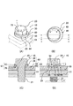
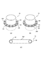
本実施形態においての第二ワッシャ40は、ねじ体の軸から偏芯した外周縁を部分がワッシャ側係合部44に設定され、このワッシャ側係合部44が被締結体50の一部に係合して特定方向における相対回転を防止するように構成されているが、ワッシャ側係合部44の設定はこれに限らず、例えば、図3に示すように構成することも可能である。図3(A)に示す第二ワッシャ140は平面形状が略ベル形に設定され、表裏に貫穿された第二ワッシャ雄ねじ挿通孔145の軸からの距離が非一様の外形を有し、その非一様に設定される外形がワッシャ側係合部44の役割を果たすように設定される。図3(B)に示す第二ワッシャ240は、ドロップ形を成し、表裏に貫穿された第二ワッシャ雄ねじ挿通孔245の軸からの距離が非一様の外形を有し、その非一様に設定される外形がワッシャ側係合部44の役割を果たすように設定される。図3(C)に示す第二ワッシャ340は、表裏に貫穿された二つの第二ワッシャ雄ねじ挿通孔345を有して二本の雄ねじ体20,20を挿通することが可能に構成され、一方の第二ワッシャ雄ねじ挿通孔345に挿通される雄ねじ体20が他方の第二ワッシャ雄ねじ挿通孔345に挿通される雄ねじ体20により特定方向の相対回転Rを防止する、軸からの距離が非一様のワッシャ側係合部44の役割を果たすように構成される(図4(C)参照)。
In the
図3に示した第二ワッシャを用いた締結例を、図4に示す。図4(A)と図4(B)は、フランジパイプの接合部におけるフランジ状被締結体150,151を被締結体とした締結系である。図4(A)においては、ベル形を成す第二ワッシャ140の異径部であるワッシャ側係合部がフランジパイプのパイプ表面に当接して、被締結体150,151に対する相対回転が防止されるように構成されている。図4(B)においては、ドロップ形を成す第二ワッシャ240の異径部であるワッシャ側係合部がフランジパイプのパイプ表面に当接して、被締結体150,151に対する相対回転が防止されるように構成されている。
FIG. 4 shows an example of fastening using the second washer shown in FIG. FIGS. 4A and 4B show a fastening system in which the flange-like fastened
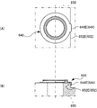
図1で示した第二ワッシャ40は、ねじ体の軸から偏芯した外周縁がワッシャ側係合部44に設定されているが、本発明はこれに限定されない。例えば、図5(A)に示す第二ワッシャ440は、外周縁が、ねじの軸心に対して同心の部分円弧形状Sとし、残部を弦Gのように直線状に切り落としたような形状となっている。この構造によれば、ワッシャ側係合部444は、ねじの軸心からの距離が非一定となる(周方向に沿って変動する)。
In the
一方、被締結体450の雄ねじ挿通孔の周囲に形成される被締結体側座部452も、第二ワッシャ440と略合同に凹設される。従って、弦Gの形状によって、ワッシャ側係合部444と被締結体側座部452が係合し、周方向の相対回転が規制される。
On the other hand, the fastened body
また図5(B)に示されるように、第二ワッシャ440外周縁が、ねじの軸心に対して同心の部分円弧形状Sとし、残部には、半径方向に延びる突起Tを形成することが出来る。この際、被締結体側座部452の内壁に、半径方向に凹む窪みKを形成する。この突起Tと窪みKの係合によって両者が係合し、周方向の相対回転が規制される。なお、特に図示しないが、これとは逆に、第二ワッシャ440外周縁に半径方向に凹となる窪み(切欠き)を形成し、被締結体側座部452側に半径方向内側に突出する突起を形成することも出来る。
As shown in FIG. 5B, the outer periphery of the
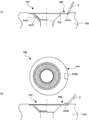
また、図1で示した第二ワッシャ40のワッシャ側係合部44は、被締結体50に対向する面が平面となる場合を例示しているが、本発明はこれに限定されない。例えば、図6(A)に示す第二ワッシャ540のワッシャ側係合部544ように、被締結体550に対向する面の一部に、ねじの軸心を中心とした円錐型等のテーパ部544Cを形成しても良い。この場合、被締結体550の被締結体側座部552にもテーパ部552Cを形成する。このように、互いのテーパ部を当接させることで、被締結体550と第二ワッシャ540の同軸度を高めると同時に、接触面積を広げることが可能となる。また、この事例で示すように、第二ワッシャ540の外周縁となるワッシャ側係合部544と、被締結体側座部552の内壁との間に隙間を形成しておき、更に、ワッシャ側係合部544の外壁に傾斜面544Aを形成することで、分解する時には、マイナスドライバDの先端を、第二ワッシャ540の背面側(被締結体550側)に挿入できるようにする。このようにすると、ワッシャ側係合部544の一部をマイナスドライバD等で持ち上げることにより、強制的に、被締結体側座部552との周方向の係合を解除できる。
Moreover, although the washer
また、図6(B)に示されるように、第二ワッシャ540の周縁に、被締結体550から離れるような挿入用凹部544Bを形成してもよい。この挿入用凹部544Bを介して、マイナスドライバDの先端を背面側に挿入出来る。
Further, as shown in FIG. 6B, an
図4(A)及び(B)では、フランジ状被締結体150,151が周囲に凸状の段部(フランジパイプ)を備えており、第二ワッシャ140,240のワッシャ側係合部を段部(フランジパイプ)のパイプ表面に当接させて、被締結体150,151と第二ワッシャ140の相対回転が防止する場合を例示した。一方、図7(A)及び(B)のように、被締結体650自身が、被締結体側座部652として、その周囲に凹状の被締結体側段部652Eを備える場合がある。この場合、第二ワッシャ640のワッシャ側係合部644として、ねじの軸線方向に延びるワッシャ側段部644Eを形成する。具体的にワッシャ側段部644Eは、被締結部材650側に屈曲する爪となっており、このワッシャ側段部644Eと、被締結体側段部652Eのねじの軸心からの距離を、互いに一致させる。従って、ワッシャ側段部644Eと被締結体側段部652Eを係合させることで、両者の相対回転が防止される。
4 (A) and 4 (B), the flange-like fastened
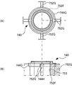
図7の応用構造を図8に示す。図8(A)のように、被締結体750が、内部に雌ねじ孔753を有する円筒形状部752Fと、その強度を高めるために周囲に四方に延びる板状のリブ752Gとを備える場合がある。この場合は、第二ワッシャ740の周縁に、ねじの軸線方向に延びる環状のワッシャ側段部744Gを形成する。このワッシャ側段部744Gが、円筒形状の被締結体750に覆い被さる。ワッシャ側段部744Gには、リブ752Gとの干渉を避けるための切欠き744Hが形成される。この切欠き744Hの内周面がワッシャ側係合部744となり、リブ752Gと係合して、両者の相対回転が抑制される。
Fig. 8 shows the applied structure of Fig. 7. As shown in FIG. 8A, the body to be fastened 750 may include a
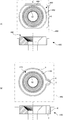
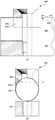
更に図9(A)に示すように、被締結体850がパイプ材で構成されており、被締結体側座部852となる被締結体側傾斜面852Jが、パイプ材の外周面となる場合がある。この場合、第二ワッシャ840におけるワッシャ側係合部844として、被締結体850に対向するワッシャ側傾斜面844Jを備えるようにできる。このワッシャ側傾斜面844Jは、ねじ軸に対して傾斜した軸(被締結体850のパイプ材の軸と同軸状態の軸)を有する仮想円柱の部分周面を含む曲面で構成される。
Further, as shown in FIG. 9A, the fastened
具体的に図9(B)のように、ワッシャ側傾斜面844Jは、ねじ軸の軸線上の適宜位置の軸直角断面の形状(断面線G)が、軸心からの距離が変位する領域を含む。同様に、被締結体側傾斜面852Jも、ねじ軸の軸線上の適宜位置の軸直角断面の形状(断面線G)が、軸心からの距離が変位する領域を含んでいる。結果、ワッシャ側傾斜面844Jと被締結体側傾斜面852Jを当接させると、互いに周方向に係合して両者の相対回転が防止される。
Specifically, as shown in FIG. 9B, the washer-side
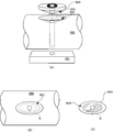
図10(A)に示すように、被締結体950の被締結体側座部952が、楕円の半球体のような凹形状となっており、その底面の中心に雌ねじ孔が形成される場合がある。この場合、第二ワッシャ940のワッシャ側係合部844を、軸に対して直角方向の断面形状が楕円に近似するような楕円半球体の突起とする。
As shown in FIG. 10A, the fastened body
図10(B)及び(C)に示すように、被締結体側座部952及びワッシャ側係合部844は、共に楕円形状となることから、軸線上の適宜位置の軸直角断面の形状(断面線G)が、軸心を基準に変位する領域を含むことになる。従って、被締結体側座部952の凹部と、ワッシャ側係合部844の突起を嵌めあわせれば、両者の相対回転を防止できる。
As shown in FIGS. 10B and 10C, since the fastened body
また、上記実施形態では、雄型のねじ体の頭部と被締結体の間に、第一及び第二ワッシャを介在させる場合を例示しているが、本発明はこれに限定されず、雌型のねじ体と、被締結体の間に上記の第一及び第二ワッシャを介在させることができる。 Moreover, although the case where the 1st and 2nd washer is interposed between the head of a male screw body and a to-be-fastened body is illustrated in the said embodiment, this invention is not limited to this, A female The first and second washers can be interposed between the screw body of the mold and the fastened body.
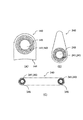
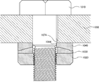
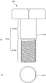
更に図11乃至図13に示すように、雌型ねじ体1020と被締結体1050の間に、第一ワッシャ1030、第二ワッシャ1040を介在させる場合において、第二ワッシャ1040を、相手側となる雄型ねじ体1070の軸部に対して周方向に係合させても良い。例えば、図13に示すように、第二ワッシャ1040の内周面に、ねじの軸心からの距離が非一定となるワッシャ側係合部1044を形成する。具体的に第二ワッシャ1040の内周面は、ねじの軸心に対して同心となる部分円弧形状となっており、残部を弦のように直線状にした形状となっている。一方、図12に示すように、雄型ねじ体1070の軸部1072の円筒部1072Aにも、軸心からの距離が非一定となる雄型ねじ体側係合部1074を形成する。
Further, as shown in FIGS. 11 to 13, when the
従って、第二ワッシャ1040に雄型ねじ体1070の軸部1072を挿入すると、ワッシャ側係合部1044と、雄型ねじ体側係合部1074が当接し、両者の周方向の相対回転を規制することができる。
Therefore, when the
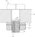
なお、この応用例として、図14及び図15に示すように、雄型ねじ体1170の軸部1172の雄ねじ部1172Bと重なるように、雄型ねじ体側係合部1174を形成することもできる。この雄型ねじ体側係合部1174は、軸方向から視た場合に、ねじ山の頂点に沿って形成される断面正円形の一部の円弧が、その弦に沿って省略(又はカット)されたような形状となっている。即ち、ねじ山の一部が軸方向に連なるよう省略されることで、半径方向に対して直角且つ半径方向外側に向いた仮想平面Pが構成され、この仮想平面Pが雄型ねじ体側係合部1174となる。なお、雄型ねじ体側係合部1174においても、ねじ山の谷底を残存させておくことが好ましく、雌型ねじ体1120と螺合する機能を維持できる。
As an application example, as shown in FIGS. 14 and 15, the male screw body
従って、第二ワッシャ1140に、雄型ねじ体1170の軸部1172を挿入すると、ワッシャ側係合部1144と、雄型ねじ体側係合部1174が当接し、両者の周方向の相対回転を規制することができる。
Therefore, when the
以上説明したねじ体20の逆回転防止構造10は、本発明の主旨を逸脱しない範囲で種々の変更が可能である。
The reverse
Claims (6)
上記ねじ体は、上記第一ワッシャと対向するねじ体側座部を有し、
上記第一ワッシャは、上記ねじ体側座部と対向する第一受部、及び、上記第二ワッシャと対向する第二受部を有し、
上記第二ワッシャは、上記第二受部と対向する第三受部、及び、被締結体側座部を有する被締結体と対向する第四受部を有し、
上記ねじ体側座部と上記第一受部の間には、該ねじ体側座部に対して特定方向の回転力が作用しても互いに係合する状態が保持される第一係合機構が構成され、
上記第二受部と上記第三受部の間には、該第二受部又は該第三受部に対して特定方向の回転力が作用しても互いに係合する状態が保持される第二係合機構が構成され、
上記第二ワッシャは、内周面、上記第四受部又は該第四受部の周囲のいずれかにおいて、上記ねじ体の軸からの距離が非一定のワッシャ側係合部を有し、
上記ワッシャ側係合部が、上記被締結体の一部又は相手側ねじ体の一部に係合することで、該第二ワッシャに対して前記特定方向の回転力が作用しても互いの係合状態が保持される第三係合機構が構成され、
上記第一係合機構により、上記ねじ体と上記第一ワッシャとの間における上記特定方向の相対回転が防止され、且つ、上記第二係合機構により、上記第一ワッシャと上記第二ワッシャとの間における上記特定方向の相対回転が防止され、且つ、上記第三係合機構により、上記第二ワッシャと上記被締結体又は上記相手側ねじ体との間における上記特定方向の相対回転が防止されることによって、該ねじ体と該被締結体又は上記相手側ねじ体との間における該特定方向の相対回転が防止されることを特徴とするねじ体の逆回転防止構造。 A screw body having a thread, a first washer, and a second washer;
The screw body has a screw body side seat portion facing the first washer,
The first washer has a first receiving part facing the screw body side seat part, and a second receiving part facing the second washer,
The second washer has a third receiving portion facing the second receiving portion, and a fourth receiving portion facing the fastened body having a fastened body side seat portion,
A first engagement mechanism is configured between the screw body side seat portion and the first receiving portion so that the screw body side seat portion is maintained in an engaged state even when a rotational force in a specific direction acts on the screw body side seat portion. And
Between the second receiving portion and the third receiving portion, a state in which the second receiving portion and the third receiving portion are engaged with each other is maintained even if a rotational force in a specific direction acts on the second receiving portion or the third receiving portion. A two-engagement mechanism is configured,
The second washer has a washer-side engaging portion whose distance from the shaft of the screw body is non-constant at any of the inner peripheral surface, the fourth receiving portion or the periphery of the fourth receiving portion,
Even if a rotational force in the specific direction acts on the second washer by engaging the washer-side engaging portion with a part of the fastened body or a part of the mating screw body, A third engagement mechanism that holds the engagement state is configured,
The first engagement mechanism prevents relative rotation in the specific direction between the screw body and the first washer, and the second engagement mechanism causes the first washer and the second washer to Relative rotation in the specific direction is prevented, and the third engagement mechanism prevents relative rotation in the specific direction between the second washer and the fastened body or the mating screw body. By doing so, the relative rotation in the specific direction between the screw body and the fastened body or the mating screw body is prevented.
前記ねじ体の軸を中心とする周方向において傾斜する傾斜面を有し、この傾斜面の傾斜角が該ねじ体の前記ねじ山の成すリード角よりも大きく設定されることによって、前記特定方向の相対回転が防止されるように構成されることを特徴とする請求の範囲1に記載のねじ体の逆回転防止構造。 One of the first engagement mechanism and the second engagement mechanism is
An inclined surface that is inclined in a circumferential direction around the axis of the screw body, and an inclination angle of the inclined surface is set to be larger than a lead angle formed by the screw thread of the screw body; 2. The structure for preventing reverse rotation of a screw body according to claim 1, wherein relative rotation of the screw body is prevented.
前記第二係合機構として前記第二受部に第二受部側凹凸が形成され且つ前記第三受部に該第二受部側凹凸と係合する第三受部側凹凸が形成されるようになっており、
これら何れかによって、前記特定方向の相対回転を防止する係合状態を得る様に構成されることを特徴とする請求の範囲1又は2に記載のねじ体の逆回転防止構造。 As the first engagement mechanism, a screw body side unevenness is formed on the screw body side seat portion and a first receiving portion side unevenness engaging with the screw body side unevenness is formed on the first receiving portion, or
As the second engagement mechanism, a second receiving portion side unevenness is formed in the second receiving portion, and a third receiving portion side unevenness engaging with the second receiving portion side unevenness is formed in the third receiving portion. And
3. The screw body reverse rotation prevention structure according to claim 1, wherein the screw body is configured so as to obtain an engagement state that prevents relative rotation in the specific direction.
上記鋸歯形状は、前記特定方向の相対回転と逆向きの相対回転は許容し得、該特定方向の相対回転は防止されるように構成されることを特徴とする請求の範囲3に記載のねじ体の逆回転防止構造。 The unevenness is a saw blade shape provided in the circumferential direction,
The screw according to claim 3, wherein the sawtooth shape is configured to allow relative rotation in a direction opposite to the relative rotation in the specific direction, and to prevent relative rotation in the specific direction. Body reverse rotation prevention structure.
前記第二ワッシャ側傾斜面は、前記ねじ体の軸に直角となる断面形状が、該ねじ体の周方向に沿って軸心からの距離が変位する領域を含み、
前記第二ワッシャ側傾斜面が前記被締結体の前記被締結体側座部に係合することで、前記第二ワッシャに対して前記特定方向の回転力が作用しても互いの係合状態が保持される前記第三係合機構が構成されることを特徴とする請求の範囲1乃至4のいずれかに記載のねじ体の逆回転防止構造。 The fourth receiving portion of the second washer has a second washer side inclined surface facing the fastened body,
The second washer-side inclined surface includes a region in which a cross-sectional shape perpendicular to the axis of the screw body is displaced in a distance from the axis along the circumferential direction of the screw body,
The second washer-side inclined surface is engaged with the fastened body side seat portion of the fastened body so that the engagement state is maintained even when a rotational force in the specific direction acts on the second washer. The reverse rotation prevention structure for a screw body according to any one of claims 1 to 4, wherein the third engagement mechanism to be held is configured.
請求の範囲5に記載のねじ体の逆回転防止構造。 The second washer-side inclined surface includes a curved surface,
The structure for preventing reverse rotation of the screw body according to claim 5.
Applications Claiming Priority (2)
| Application Number | Priority Date | Filing Date | Title |
|---|---|---|---|
| JP2013221692 | 2013-10-25 | ||
| JP2013-221692 | 2013-10-25 |
Publications (1)
| Publication Number | Publication Date |
|---|---|
| WO2015060425A1 true WO2015060425A1 (en) | 2015-04-30 |
Family
ID=52993010
Family Applications (1)
| Application Number | Title | Priority Date | Filing Date |
|---|---|---|---|
| PCT/JP2014/078352 Ceased WO2015060425A1 (en) | 2013-10-25 | 2014-10-24 | Reverse rotation prevention structure for screw body |
Country Status (2)
| Country | Link |
|---|---|
| TW (1) | TWI652413B (en) |
| WO (1) | WO2015060425A1 (en) |
Cited By (7)
| Publication number | Priority date | Publication date | Assignee | Title |
|---|---|---|---|---|
| JP2016223523A (en) * | 2015-05-29 | 2016-12-28 | 株式会社マルナカ | Washer and nut with washer |
| JP2017110787A (en) * | 2015-12-18 | 2017-06-22 | 一夫 中島 | Washer, nut, bolt, nut with washer and bolt with washer |
| CN109193534A (en) * | 2018-09-10 | 2019-01-11 | 广东电网有限责任公司 | A shockproof hammer |
| JP2019178725A (en) * | 2018-03-30 | 2019-10-17 | 株式会社フジキン | Pipe joint |
| CN110529487A (en) * | 2019-09-12 | 2019-12-03 | 上海三一重机股份有限公司 | Retention device, locking device and excavator |
| JP2020505559A (en) * | 2017-01-06 | 2020-02-20 | シバス エレクトロニクス (シアメン) カンパニー リミテッド | Lock devices and connectors |
| CN116624495A (en) * | 2023-05-29 | 2023-08-22 | 中煤科工集团重庆研究院有限公司 | Anti-loosening bolt combination and its usage method |
Citations (7)
| Publication number | Priority date | Publication date | Assignee | Title |
|---|---|---|---|---|
| WO2001088391A1 (en) * | 2000-05-19 | 2001-11-22 | Eisuke Ishida | Structure for preventing loosening of threaded fasteners |
| JP2002206515A (en) * | 2001-01-12 | 2002-07-26 | Teruo Nakagami | Fastening structure for locking and nut and washer for the fastening structure |
| JP2005226764A (en) * | 2004-02-13 | 2005-08-25 | Amachi:Kk | Washer with nut lock mechanism |
| JP2010288356A (en) * | 2009-06-11 | 2010-12-24 | Mitsubishi Electric Corp | Washers and fixing devices |
| JP2011252573A (en) * | 2010-06-03 | 2011-12-15 | Iifas Co Ltd | Locking washer and locking fastener using the same |
| JP2012511671A (en) * | 2008-12-09 | 2012-05-24 | サン−チョル イ | Loosening prevention bolt and nut combination |
| JP2012102783A (en) * | 2010-11-09 | 2012-05-31 | Yoshiro Takiguchi | Fastening tool |
-
2014
- 2014-10-24 WO PCT/JP2014/078352 patent/WO2015060425A1/en not_active Ceased
- 2014-10-27 TW TW103136962A patent/TWI652413B/en active
Patent Citations (7)
| Publication number | Priority date | Publication date | Assignee | Title |
|---|---|---|---|---|
| WO2001088391A1 (en) * | 2000-05-19 | 2001-11-22 | Eisuke Ishida | Structure for preventing loosening of threaded fasteners |
| JP2002206515A (en) * | 2001-01-12 | 2002-07-26 | Teruo Nakagami | Fastening structure for locking and nut and washer for the fastening structure |
| JP2005226764A (en) * | 2004-02-13 | 2005-08-25 | Amachi:Kk | Washer with nut lock mechanism |
| JP2012511671A (en) * | 2008-12-09 | 2012-05-24 | サン−チョル イ | Loosening prevention bolt and nut combination |
| JP2010288356A (en) * | 2009-06-11 | 2010-12-24 | Mitsubishi Electric Corp | Washers and fixing devices |
| JP2011252573A (en) * | 2010-06-03 | 2011-12-15 | Iifas Co Ltd | Locking washer and locking fastener using the same |
| JP2012102783A (en) * | 2010-11-09 | 2012-05-31 | Yoshiro Takiguchi | Fastening tool |
Cited By (8)
| Publication number | Priority date | Publication date | Assignee | Title |
|---|---|---|---|---|
| JP2016223523A (en) * | 2015-05-29 | 2016-12-28 | 株式会社マルナカ | Washer and nut with washer |
| JP2017110787A (en) * | 2015-12-18 | 2017-06-22 | 一夫 中島 | Washer, nut, bolt, nut with washer and bolt with washer |
| JP2020505559A (en) * | 2017-01-06 | 2020-02-20 | シバス エレクトロニクス (シアメン) カンパニー リミテッド | Lock devices and connectors |
| JP2019178725A (en) * | 2018-03-30 | 2019-10-17 | 株式会社フジキン | Pipe joint |
| JP7029801B2 (en) | 2018-03-30 | 2022-03-04 | 株式会社フジキン | Pipe fittings |
| CN109193534A (en) * | 2018-09-10 | 2019-01-11 | 广东电网有限责任公司 | A shockproof hammer |
| CN110529487A (en) * | 2019-09-12 | 2019-12-03 | 上海三一重机股份有限公司 | Retention device, locking device and excavator |
| CN116624495A (en) * | 2023-05-29 | 2023-08-22 | 中煤科工集团重庆研究院有限公司 | Anti-loosening bolt combination and its usage method |
Also Published As
| Publication number | Publication date |
|---|---|
| TW201530001A (en) | 2015-08-01 |
| TWI652413B (en) | 2019-03-01 |
Similar Documents
| Publication | Publication Date | Title |
|---|---|---|
| JP5336644B1 (en) | Screw body reverse rotation prevention structure | |
| KR102180200B1 (en) | Structure for preventing reverse rotation of threaded body | |
| JP2020125849A (en) | Male screw body, cooperation member, female screw body, fastening structure of screw body | |
| JP3234710U (en) | Anti-vibration nut kit | |
| JP3213541U (en) | Nut with nylon washer | |
| JP5235237B1 (en) | Double nut | |
| TWI652413B (en) | Anti-reverse structure of threaded body | |
| KR102082598B1 (en) | Installation device | |
| JP2019039555A (en) | Looseness prevention fastening structure | |
| JP6039515B2 (en) | Screw body reverse rotation prevention structure | |
| JP2020112263A (en) | Locking fastening structure | |
| JP2022173514A (en) | Reverse rotation prevention structure of screw fastening mechanism and inclusion member of screw fastening mechanism | |
| JP6421307B2 (en) | Screw body reverse rotation prevention structure | |
| JP6083632B1 (en) | Locking nut | |
| WO2020031252A1 (en) | Lock washer and fastening structure | |
| JP5677012B2 (en) | Fastening member | |
| JP3182560U (en) | Multiple lock nuts | |
| JP5957632B2 (en) | Locking nut | |
| JP6387507B2 (en) | Screw body reverse rotation prevention structure | |
| JP2015209971A (en) | Speed nut | |
| WO2016063431A1 (en) | Fastener, fastening structure for fastener, hinge structure, and male fastener | |
| JP2005014640A (en) | Wheel nut and wheel bolt | |
| JP2023175593A (en) | Looseness prevention nut | |
| JP2016099002A (en) | Locking nut | |
| JP2014084927A (en) | Locking screw |
Legal Events
| Date | Code | Title | Description |
|---|---|---|---|
| 121 | Ep: the epo has been informed by wipo that ep was designated in this application |
Ref document number: 14856049 Country of ref document: EP Kind code of ref document: A1 |
|
| NENP | Non-entry into the national phase |
Ref country code: DE |
|
| 122 | Ep: pct application non-entry in european phase |
Ref document number: 14856049 Country of ref document: EP Kind code of ref document: A1 |
|
| NENP | Non-entry into the national phase |
Ref country code: JP |
|
| NENP | Non-entry into the national phase |
Ref country code: JP |