WO2015056582A1 - Electricity-supplying structure, resin plate for window provided with said structure, and method for manufacturing resin plate for window provided with electricity-supplying structure - Google Patents
Electricity-supplying structure, resin plate for window provided with said structure, and method for manufacturing resin plate for window provided with electricity-supplying structure Download PDFInfo
- Publication number
- WO2015056582A1 WO2015056582A1 PCT/JP2014/076537 JP2014076537W WO2015056582A1 WO 2015056582 A1 WO2015056582 A1 WO 2015056582A1 JP 2014076537 W JP2014076537 W JP 2014076537W WO 2015056582 A1 WO2015056582 A1 WO 2015056582A1
- Authority
- WO
- WIPO (PCT)
- Prior art keywords
- resin
- power feeding
- plate
- power supply
- conductive portion
- Prior art date
Links
Images


Classifications
-
- B—PERFORMING OPERATIONS; TRANSPORTING
- B60—VEHICLES IN GENERAL
- B60L—PROPULSION OF ELECTRICALLY-PROPELLED VEHICLES; SUPPLYING ELECTRIC POWER FOR AUXILIARY EQUIPMENT OF ELECTRICALLY-PROPELLED VEHICLES; ELECTRODYNAMIC BRAKE SYSTEMS FOR VEHICLES IN GENERAL; MAGNETIC SUSPENSION OR LEVITATION FOR VEHICLES; MONITORING OPERATING VARIABLES OF ELECTRICALLY-PROPELLED VEHICLES; ELECTRIC SAFETY DEVICES FOR ELECTRICALLY-PROPELLED VEHICLES
- B60L1/00—Supplying electric power to auxiliary equipment of vehicles
- B60L1/02—Supplying electric power to auxiliary equipment of vehicles to electric heating circuits
-
- B—PERFORMING OPERATIONS; TRANSPORTING
- B29—WORKING OF PLASTICS; WORKING OF SUBSTANCES IN A PLASTIC STATE IN GENERAL
- B29C—SHAPING OR JOINING OF PLASTICS; SHAPING OF MATERIAL IN A PLASTIC STATE, NOT OTHERWISE PROVIDED FOR; AFTER-TREATMENT OF THE SHAPED PRODUCTS, e.g. REPAIRING
- B29C45/00—Injection moulding, i.e. forcing the required volume of moulding material through a nozzle into a closed mould; Apparatus therefor
- B29C45/14—Injection moulding, i.e. forcing the required volume of moulding material through a nozzle into a closed mould; Apparatus therefor incorporating preformed parts or layers, e.g. injection moulding around inserts or for coating articles
- B29C45/14639—Injection moulding, i.e. forcing the required volume of moulding material through a nozzle into a closed mould; Apparatus therefor incorporating preformed parts or layers, e.g. injection moulding around inserts or for coating articles for obtaining an insulating effect, e.g. for electrical components
-
- B—PERFORMING OPERATIONS; TRANSPORTING
- B60—VEHICLES IN GENERAL
- B60J—WINDOWS, WINDSCREENS, NON-FIXED ROOFS, DOORS, OR SIMILAR DEVICES FOR VEHICLES; REMOVABLE EXTERNAL PROTECTIVE COVERINGS SPECIALLY ADAPTED FOR VEHICLES
- B60J1/00—Windows; Windscreens; Accessories therefor
- B60J1/002—Windows; Windscreens; Accessories therefor with means for clear vision, e.g. anti-frost or defog panes, rain shields
-
- B—PERFORMING OPERATIONS; TRANSPORTING
- B60—VEHICLES IN GENERAL
- B60J—WINDOWS, WINDSCREENS, NON-FIXED ROOFS, DOORS, OR SIMILAR DEVICES FOR VEHICLES; REMOVABLE EXTERNAL PROTECTIVE COVERINGS SPECIALLY ADAPTED FOR VEHICLES
- B60J1/00—Windows; Windscreens; Accessories therefor
- B60J1/08—Windows; Windscreens; Accessories therefor arranged at vehicle sides
-
- B—PERFORMING OPERATIONS; TRANSPORTING
- B60—VEHICLES IN GENERAL
- B60J—WINDOWS, WINDSCREENS, NON-FIXED ROOFS, DOORS, OR SIMILAR DEVICES FOR VEHICLES; REMOVABLE EXTERNAL PROTECTIVE COVERINGS SPECIALLY ADAPTED FOR VEHICLES
- B60J1/00—Windows; Windscreens; Accessories therefor
- B60J1/18—Windows; Windscreens; Accessories therefor arranged at the vehicle rear
-
- B—PERFORMING OPERATIONS; TRANSPORTING
- B60—VEHICLES IN GENERAL
- B60J—WINDOWS, WINDSCREENS, NON-FIXED ROOFS, DOORS, OR SIMILAR DEVICES FOR VEHICLES; REMOVABLE EXTERNAL PROTECTIVE COVERINGS SPECIALLY ADAPTED FOR VEHICLES
- B60J7/00—Non-fixed roofs; Roofs with movable panels, e.g. rotary sunroofs
- B60J7/02—Non-fixed roofs; Roofs with movable panels, e.g. rotary sunroofs of sliding type, e.g. comprising guide shoes
- B60J7/04—Non-fixed roofs; Roofs with movable panels, e.g. rotary sunroofs of sliding type, e.g. comprising guide shoes with rigid plate-like element or elements, e.g. open roofs with harmonica-type folding rigid panels
- B60J7/043—Sunroofs e.g. sliding above the roof
-
- H—ELECTRICITY
- H01—ELECTRIC ELEMENTS
- H01Q—ANTENNAS, i.e. RADIO AERIALS
- H01Q1/00—Details of, or arrangements associated with, antennas
- H01Q1/12—Supports; Mounting means
- H01Q1/1271—Supports; Mounting means for mounting on windscreens
-
- B—PERFORMING OPERATIONS; TRANSPORTING
- B29—WORKING OF PLASTICS; WORKING OF SUBSTANCES IN A PLASTIC STATE IN GENERAL
- B29K—INDEXING SCHEME ASSOCIATED WITH SUBCLASSES B29B, B29C OR B29D, RELATING TO MOULDING MATERIALS OR TO MATERIALS FOR MOULDS, REINFORCEMENTS, FILLERS OR PREFORMED PARTS, e.g. INSERTS
- B29K2069/00—Use of PC, i.e. polycarbonates or derivatives thereof, as moulding material
-
- B—PERFORMING OPERATIONS; TRANSPORTING
- B29—WORKING OF PLASTICS; WORKING OF SUBSTANCES IN A PLASTIC STATE IN GENERAL
- B29K—INDEXING SCHEME ASSOCIATED WITH SUBCLASSES B29B, B29C OR B29D, RELATING TO MOULDING MATERIALS OR TO MATERIALS FOR MOULDS, REINFORCEMENTS, FILLERS OR PREFORMED PARTS, e.g. INSERTS
- B29K2701/00—Use of unspecified macromolecular compounds for preformed parts, e.g. for inserts
- B29K2701/12—Thermoplastic materials
-
- B—PERFORMING OPERATIONS; TRANSPORTING
- B29—WORKING OF PLASTICS; WORKING OF SUBSTANCES IN A PLASTIC STATE IN GENERAL
- B29K—INDEXING SCHEME ASSOCIATED WITH SUBCLASSES B29B, B29C OR B29D, RELATING TO MOULDING MATERIALS OR TO MATERIALS FOR MOULDS, REINFORCEMENTS, FILLERS OR PREFORMED PARTS, e.g. INSERTS
- B29K2705/00—Use of metals, their alloys or their compounds, for preformed parts, e.g. for inserts
- B29K2705/08—Transition metals
- B29K2705/10—Copper
-
- B—PERFORMING OPERATIONS; TRANSPORTING
- B29—WORKING OF PLASTICS; WORKING OF SUBSTANCES IN A PLASTIC STATE IN GENERAL
- B29K—INDEXING SCHEME ASSOCIATED WITH SUBCLASSES B29B, B29C OR B29D, RELATING TO MOULDING MATERIALS OR TO MATERIALS FOR MOULDS, REINFORCEMENTS, FILLERS OR PREFORMED PARTS, e.g. INSERTS
- B29K2705/00—Use of metals, their alloys or their compounds, for preformed parts, e.g. for inserts
- B29K2705/08—Transition metals
- B29K2705/14—Noble metals, e.g. silver, gold or platinum
-
- B—PERFORMING OPERATIONS; TRANSPORTING
- B29—WORKING OF PLASTICS; WORKING OF SUBSTANCES IN A PLASTIC STATE IN GENERAL
- B29K—INDEXING SCHEME ASSOCIATED WITH SUBCLASSES B29B, B29C OR B29D, RELATING TO MOULDING MATERIALS OR TO MATERIALS FOR MOULDS, REINFORCEMENTS, FILLERS OR PREFORMED PARTS, e.g. INSERTS
- B29K2995/00—Properties of moulding materials, reinforcements, fillers, preformed parts or moulds
- B29K2995/0018—Properties of moulding materials, reinforcements, fillers, preformed parts or moulds having particular optical properties, e.g. fluorescent or phosphorescent
- B29K2995/0026—Transparent
-
- B—PERFORMING OPERATIONS; TRANSPORTING
- B29—WORKING OF PLASTICS; WORKING OF SUBSTANCES IN A PLASTIC STATE IN GENERAL
- B29L—INDEXING SCHEME ASSOCIATED WITH SUBCLASS B29C, RELATING TO PARTICULAR ARTICLES
- B29L2031/00—Other particular articles
- B29L2031/30—Vehicles, e.g. ships or aircraft, or body parts thereof
- B29L2031/3052—Windscreens
-
- B—PERFORMING OPERATIONS; TRANSPORTING
- B60—VEHICLES IN GENERAL
- B60Y—INDEXING SCHEME RELATING TO ASPECTS CROSS-CUTTING VEHICLE TECHNOLOGY
- B60Y2410/00—Constructional features of vehicle sub-units
- B60Y2410/12—Production or manufacturing of vehicle parts
Definitions
- the present invention relates to a power feeding structure and a resin plate-like body for windows provided with the same. Moreover, this invention relates to the manufacturing method of the resin-made plate-shaped objects for windows provided with the electric power feeding structure.
- resin-made plate-like bodies for windows have begun to be applied in place of window glass for the purpose of weight reduction, particularly in vehicle applications.
- resin plate-like bodies for windows it is difficult to print and fire a glass antenna or other conductive wire with silver paste on the surface like a window glass, so the conductive wire print formed on the surface of the resin film is a resin film.
- a resin-made plate-like body for a window with a lead wire is formed by being sandwiched between the resin panel and the resin panel. In this case, since the conductive wire print is sealed inside the resin plate for windows, it is not easy to supply power to the conductive wire print.
- Patent Document 1 discloses a metal foil as such a conductive portion.
- a power feeding structure aims at providing the manufacturing method of the resin-made plate-shaped object for windows provided.
- a resin panel and a resin film provided with a power supply target are provided with a conductive part in contact with the power supply target inside a resin plate-like body for windows configured to sandwich the power supply target.
- the conductive portion is provided on a resin sheet, and the resin sheet is disposed inside the plate-like body so as to sandwich the conductive portion between the power supply target,
- the resin panel and the resin sheet are welded, and the resin component contained in each of the power supply target and the conductive portion is welded, and a power feeding structure and a resin plate for windows having the power feeding structure The body is provided.
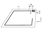
- FIG. 1 is a plan view of a resinous plate-like body 100 for windows provided with a power feeding structure according to an embodiment.
- the “resin plate-like body for a window having a power feeding structure” is referred to as “a plate-like body with a power feeding structure”.
- the plate-like body 100 with a power feeding structure is an example of a plate-like body with a power feeding structure for a side window attached to a side surface of an automobile.
- the plate-like body with a power feeding structure according to the embodiment of the present invention is not limited to the illustrated outer shape, and may be any one used for a vehicle window attached to a vehicle such as an automobile. It may be used for a rear window attached to the rear part of the vehicle, or may be used for a roof window attached to the ceiling part of the vehicle.
- the plate-like body 100 with a power feeding structure is a resin plate-like body 10 for a window provided with a conductor pattern 20.
- the window-made resin plate-like body 10 is a transparent or translucent plate-like member that is attached to a window frame of a vehicle, and is a member that includes a resin layer. Specifically, it is a resin plate-like body for a window configured by laminating a resin panel and a resin film provided with the conductor pattern 20 so as to sandwich the conductor pattern 20 therebetween.
- the conductor pattern 20 is a conductor provided in a planar manner on the resin plate 10 for windows.
- the conductor pattern 20 includes a line conductor 22 and a power feeding unit 21.
- the linear conductor 22 is a conductor formed in a linear shape on the window-made resin plate-like body 10
- the power supply unit 21 is a conductor for supplying power to the linear conductor 22.
- the power feeding unit 21 is electrically connected to the linear conductor 22 and is formed wider than the linear conductor 22.
- the conductor pattern 20 is not limited to the illustrated shape, and may be formed in any other shape.
- the wire conductor 22 and the power feeding portion 21 are formed in a state of being arranged inside the window resin plate-like body 10, but the wire conductor 22 is formed on the surface of the window resin plate-like body 10. May be.
- the line conductor 22 is, for example, capacitively coupled to the power feeding portion 21 arranged inside the window-made resin plate-like body 10. It is better to be electrically connected.
- the line conductor 22 corresponds to an antenna element or a feed line to the antenna element.
- the conductor pattern 20 is a defogger that prevents the window-made resin plate 10 from being fogged, the filament conductor 22 corresponds to a heater wire.
- the conductor pattern 20 may be used for other purposes.
- the power feeding part 21 is not limited to a part for feeding power to a linear element such as the line conductor 22 but a part for feeding power to an arbitrary conductor such as a conductive film formed on the resin plate 10 for windows. It may be.
- electric power feeding may mean supplying electric power to conductors, such as the filament conductor 22, and may mean receiving electric power from conductors, such as the filament conductor 22.
- a power supply component 30 is electrically connected to the power supply unit 21.
- the power feeding component 30 is a terminal component used for power feeding to the conductor pattern 20, and feeds power to a conductor such as the line conductor 22 through the power feeding portion 21.
- the power supply component 30 is connected to an unillustrated electric wire such as a vehicle wiring harness, and when the conductor pattern 20 is an antenna conductor, for example, is connected to an in-vehicle receiver via the electric wire, and the conductor pattern 20 is, for example, a defogger In this case, it is connected to a vehicle-mounted power source or ground via the electric wire.
- the power feeding component 30 may be a component including a signal processing circuit such as an amplifier.
- the power supply component 30 may be a simple metal terminal having electrical conductivity for electrically connecting the electric wire and the power supply unit 21.
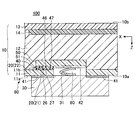
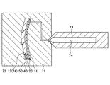
- FIG. 2 is a cross-sectional view of the plate-like body 100 with a power feeding structure in AA of FIG.
- the lower side corresponds to the vehicle inner side
- the upper side corresponds to the vehicle outer side.
- the plate-like body 100 with a power feeding structure is a resin plate-like body 10 for a window provided with a power feeding structure 80.
- the power feeding structure 80 includes a conductive portion 40 that is in contact with the surface of the power feeding portion 21 of the conductive pattern 20 disposed inside the resin plate 10 for windows, and the power feeding portion 21 of the conductor pattern 20 is interposed via the conductive portion 40. It is a structure that supplies power.
- the surface of the power feeding part 21 with which the conductive part 40 comes into contact is the inner surface of the window resin plate-like body 10 out of both surfaces of the power feeding part 21 in the plate thickness direction Z of the window resin plate-like body 10. It is.
- board thickness direction Z is a direction which sees the resin-made plate-shaped object for windows in planar view in the figure, Comprising: It is a direction parallel to a Z-axis.
- the conductor pattern 20 is an example of a power supply target that is fed by the power feeding structure 80 via the conductive portion 40.
- the power feeding structure 80 has the wire conductor 22 electrically Power is supplied to the power supply unit 21 connected to the power source via the conductive unit 40, and power is supplied to the line conductor 22 via the power supply unit 21.
- the conductive portion 40 is an example of a conductive portion that is provided on the resin sheet 50 and that contacts a power supply target disposed inside the resin plate 10 for windows.
- the conductive portion 40 is a conductive layer that is in contact with the surface of the power feeding portion 21 of the conductor pattern 20 in the plate thickness direction Z, and is a conductor disposed inside the resin plate 10 for windows.
- the power feeding structure 80 includes a resin sheet 50 arranged inside the window-made resin plate 10 so that the conductive portion 40 is sandwiched between the power feeding portion 21 of the conductor pattern 20.
- the resin sheet 50 is disposed inside the window resin plate 10 so as to sandwich a conductive portion in contact with the power supply target between the resin sheet 50 and the power supply target disposed inside the window resin plate 10. This is an example of a resin sheet.
- the resin sheet 50 is a resinous sheet having a surface 51 that contacts the surface of the conductive portion 40 opposite to the power feeding portion 21.
- the surface 51 is a surface that faces the power feeding unit 21 side among both surfaces of the resin sheet 50 in the plate thickness direction Z.
- the resin sheet 50 may be, for example, a transparent polycarbonate sheet, or may be a sheet made of a multilayer material combined with other materials.
- the resin sheet 50 is a resin material that is disposed enclosed in the resin panel 12. Since the resin sheet 50 is made of the same resin component as that of the resin panel 12, the resin sheet 50 and the resin panel 12 are firmly welded to obtain a stable bond.
- the resin panel 12 is a resin panel configured inside the resin plate 10 for windows, and is an injection-molded resin material.
- the resin panel 12 is, for example, a transparent plate-like polycarbonate.
- the conductive portion 40 Since the conductive portion 40 is sandwiched between the power feeding portion 21 of the conductor pattern 20 and the resin sheet 50 disposed in the resin panel 12, stable bonding of the conductive portion 40 can be ensured. For example, the size of the portion where the conductive portion 40 and the resin panel 12 are in contact with each other can be reduced by the interposition of the resin sheet 50. In the case of FIG. 2, the conductive portion 40 does not have a portion to be joined to the resin panel 12 in the plate thickness direction Z, and a portion that contacts the resin panel 12 only in a direction parallel to the XY plane orthogonal to the plate thickness direction Z. Have. As described above, since the size of the contact portion between the conductive portion 40 and the resin panel 12 is reduced, the conductive portion 40 is stabilized to the resin panel 12 even if the expansion rates of the conductive portion 40 and the resin panel 12 are different. Can be held.
- the difference in expansion coefficient between the resin sheet 50 and the resin panel 12 is the expansion between the conductive portion 40 and the resin panel 12. Less than the rate difference. Therefore, the distortion which generate
- the conductive portion 40 and the resin sheet 50 are arranged inside the window-made resin plate 10. Therefore, the durability of the plate-like body 100 with the power feeding structure can be ensured even in a relatively large vibration environment such as a vehicle.
- the resin component 26 contained in the power feeding portion 21 of the conductor pattern 20 and the resin component 46 contained in the conductive portion 40 are welded. Since the resin components of the resin component 26 and the resin component 46 are welded to each other, stable bonding of the conductive portion 40 can be ensured. For example, the bonding strength between the power supply unit 21 and the conductive unit 40 can be increased as compared with the case where the power supply unit 21 and the conductive unit 40 are simply in contact with each other.
- the bonding strength between the power feeding portion 21 and the conductive portion 40 is increased, even if the conductive pattern 20 or the resin panel 12 in contact with the conductive portion 40 is bent, the gap between the power feeding portion 21 and the conductive portion 40 of the conductor pattern 20 is Conductivity can be ensured reliably.
- the mark ⁇ represents the resin component schematically
- the mark x represents the metal component schematically. The same applies to the other drawings.
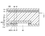
- the resin plate 10 for windows is configured as a resin layer by laminating a resin film 11 and a resin panel 12.
- the conductor pattern 20, the conductive part 40, and the resin sheet 50 are disposed between the resin film 11 and the resin panel 12.
- the resin panel 12 is joined to a part of the inner surface 11 b of the resin film 11.
- the resin film 11 is a resin film having an outer surface 11a exposed to the inside of the vehicle and an inner surface 11b opposite to the outer surface 11a.
- the outer surface 11a is a surface 10a on the vehicle interior side of the resin plate member 10 for windows.
- the outer surface 11a may be subjected to a hard coat process.
- a conductor pattern 20 is formed in a plane on the inner surface 11b.
- the resin film 11 may be, for example, a transparent polycarbonate film or a film made of a multilayer material combined with other materials.
- the power feeding portion 21 and the line conductor 22 of the conductor pattern 20 are conductive prints formed in a planar manner by screen printing a conductive ink on the inner surface 11b of the resin film 11, for example.
- the conductive ink is configured to contain silver (copper, gold, nickel, carbon, aluminum, etc. can be used) which is a conductive material.
- the resin film 11 has a thickness of 120 ⁇ m or more and 250 ⁇ m or less. By having a thickness of 120 ⁇ m or more, wrinkles are less likely to occur during injection molding.
- the conductor pattern 20 is thinner than the resin film 11 and has a thickness of 7 ⁇ m or more and 45 ⁇ m or less. Although the thickness depends on the required resistance value, the conductor pattern 20 can be stably formed by screen printing by being in this range.
- the conductive portion 40 may be formed planarly on the surface 51 of the resin sheet 50 in the same manner as the conductive pattern 20.
- the conductive portion 40 is formed planarly by screen-printing conductive ink on the surface 51 of the resin sheet 50. May be sex prints.
- the conductive ink is configured to contain silver (copper, gold, nickel, carbon, aluminum, etc. can be used) which is a conductive material.
- the resin sheet 50 has a thickness of 120 ⁇ m or more and 250 ⁇ m or less, and the conductive pattern 20 is thinner than the resin sheet 50 and has a thickness of 7 ⁇ m or more and 45 ⁇ m or less.
- the power feeding structure 80 includes, for example, a power feeding hole 60 as a power feeding hole extending from the surface 10a of the window-made resin plate 10 to the conductive portion 40.
- the surface 10 a is a surface of the conductive pattern 20 on the power feeding portion 21 side of the both surfaces 10 a and 10 b in the plate thickness direction Z of the window-made resin plate-like body 10 with respect to the conductive portion 40. Since the power supply hole 60 is provided, even if the power supply portion 21 of the conductor pattern 20 is disposed inside the window resin plate-like body 10, the power supply hole 60 and the conductive material are provided from the outside of the window resin plate-like body 10. Power can be easily supplied to the power supply unit 21 via the unit 40.
- the power supply hole 60 is formed so as to penetrate the resin film 11 from the outer surface 11 a and reach the surface 42 of the conductive portion 40 on the side facing the power supply portion 21.
- the power supply hole 60 is not limited to one and may be a plurality.
- the hole shape of the power supply hole 60 may be circular, polygonal, or any other shape.
- the power feeding structure 80 includes a power feeding component 30 that is electrically connected to the power feeding portion 21 of the conductor pattern 20 via the power feeding hole 60 and the conductive portion 40. Since the power supply hole 60 is provided, the power supply component 30 is connected via the power supply hole 60 and the conductive portion 40 even if the power supply portion 21 of the conductor pattern 20 is disposed inside the resin plate 10 for windows. Power can be supplied by being easily electrically connected to the power supply unit 21. For example, the power feeding component 30 can be easily brought into conductive contact with the surface 42 of the conductive portion 40 on the power feeding portion 21 side via the power feeding hole 60.
- the power feeding component 30 is installed on the outer surface 11 a of the resin film 11 via the adhesive 41.
- the outer surface 11a is the surface 10a of the window-made resin plate-like body 10 on the side where the power supply hole 60 opens.
- the adhesive 41 is an adhesive layer that is interposed between the resin film 11 and the power supply component 30 and adheres the resin film 11 and the power supply component 30, and specific examples thereof include an adhesive and an adhesive tape. Etc. With the adhesive 41, the power feeding component 30 can be easily attached and fixed to the outer surface 11 a of the resin film 11. Further, since the power supply component 30 can be attached to the window resin plate 10 without using a tapping screw by using the adhesive 41, the durability of the power supply structure 80 and the window resin plate 10 is improved. improves.
- the power feeding component 30 is not installed on the window resin plate 10, there is no projection protruding from the surfaces 10 a and 10 b of the window resin plate 10, so that Ease of transporting the plate-like body 10 is improved.
- the power supply component 30 is in conductive contact with the surface 42 of the conductive portion 40 via, for example, the contact portion 31 disposed in the power supply hole 60 formed in the resin plate 10 for windows.
- the contact portion 31 can further facilitate the conductive connection between the power supply component 30 and the conductive portion 40.
- the contact portion 31 is a part (component) on the power supply component 30 side, and is provided so as to protrude from the surface of the power supply component 30 on the power supply portion 21 side.
- the contact portion 31 is not a portion on the power supply component 30 side but a portion (component) on the conductive portion 40 side and may be provided so as to protrude from the surface 42 to the power supply portion 21 side.
- the contact portion 31 may be a single component or a part (component) composed of a plurality of members including a member (not shown).
- the contact portion 31 is an elastic body having conductivity
- the power feeding component 30 may be fixed to the outer surface 11a with the adhesive 41 in a state where the contact portion 31 is in contact with the surface 42 of the conductive portion 40 and is elastically deformed. As a result, even when the resin plate 10 for windows vibrates due to vehicle vibration or the like, sufficient conductivity and durability between the power supply component 30 and the conductive portion 40 are obtained by vibration absorption due to the bending of the contact portion 31. Can be secured.
- Specific examples of the elastic contact portion 31 include a leaf spring, a spring coil, and rubber.
- the power feeding component 30 may be conductively contacted with the conductive portion 40 via a conductive adhesive.
- the contact portion 31 may be bonded to the conductive portion 40 and / or the power feeding component 30 with a conductive adhesive such as a conductive adhesive or solder.
- the contact portion 31 may be a conductive adhesive or solder. It may be replaced with a conductive adhesive such as.
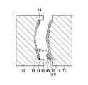
- the resinous plate-like body 10 for windows has a concealing layer 14 for concealing a part of the conductor pattern 20 and the conductive portion 40 in a plan view in the thickness direction Z from the outside of the vehicle to the inside of the vehicle.
- the power supply unit 21 may be provided on the opposite side (that is, on the resin sheet 50 side with respect to the conductive unit 40).
- the part of the conductor pattern 20 concealed by the concealing layer 14 is, for example, part or all of the power feeding unit 21.
- the concealing layer 14 is formed on the film 13 with the concealing layer that is provided on the side opposite to the power feeding unit 21 with respect to the conductive unit 40.
- the film 13 with a concealing layer is joined to the resin panel 12, and the concealing layer 14 is interposed between the resin panel 12 and the film 13 with a concealing layer.
- the film 13 with a concealing layer is, for example, a transparent polycarbonate film.
- the masking layer 14 is, for example, a black paint.
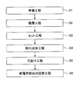
- FIG. 3 is a flowchart showing an example of a method for manufacturing the plate-like body 100 with the feeding structure.
- step S1 is a process of printing the conductive ink on the resin film 11 to form the conductor pattern 20, for example.
- the conductive portion 40 is formed by printing conductive ink on the resin sheet 50. Note that a step of baking the conductive ink and a step of evaporating the solvent by drying may be included.
- step S ⁇ b> 2 in FIG. 3 the stacking process of step S ⁇ b> 2 in FIG. 3 is performed by the resin film 11 and the resin sheet so that the conductive portion 40 is interposed between the surface 21 a of the power feeding portion 21 of the conductor pattern 20 and the resin sheet 50. 50.
- the surface 21 a is a surface on the vehicle outer side opposite to the resin film 11.
- the lamination process of step S2 is a process of superposing the resin sheet 50 on which the conductive part 40 is formed, for example, on the inner surface 11b of the resin film 11 so that the conductive part 40 and the power feeding part 21 are in contact with each other.
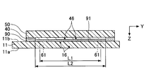
- FIG. 6 is a cross-sectional view in the YZ plane viewed from the X-axis direction of FIG.
- an adhesive portion 90 in FIG. 5, the illustration of the adhesive member 90 takes into consideration the visibility of the drawing). , Omitted).
- the adhesive portion 90 can prevent the resin sheet 50 from being separated from the resin film 11 in the setting step of Step S3 described later.
- Specific examples of the bonding part 90 include a double-sided tape and an adhesive.
- the bonding portion 90 may be a portion where the resin sheet 50 and the resin film 11 are in thermal contact with each other. For example, when the resin sheet 50 and the resin film 11 are stacked, the resin sheet 50 and the resin film 11 are heat-welded at the bonding portion 90 by heating the resin sheet 50 and the resin film 11 in the plate thickness direction Z. Can do.
- the peeling tape 91 is a welding suppression member that suppresses the resin component 46 contained in the conductive portion 40 and the resin component 16 contained in the resin film 11 from being welded by heat and pressure in an injection molding process of step S4 described later. It is.
- the welding suppression member such as the peeling tape 91 has a higher melting point than the heat at the time of injection molding so as not to melt by the heat at the time of injection molding.
- the peeling tape 91 is preferably a fluororesin or polyimide tape.
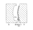
- the setting process in step S ⁇ b> 3 includes feeding the resin film 11 in which the resin sheet 50 with the conductive portion 40 is laminated and bonded to the surface 21 a of the power feeding portion 21 of the conductor pattern 20 as illustrated in FIG. 7. It is a step of setting in an injection mold for manufacturing a plate with structure.
- the injection mold is a mold having a first mold 71 and a second mold 72, for example.
- the resin film 11 is set in the mold (within the cavity) between the first mold 71 and the second mold 72 while being positioned on the first mold 71.
- Examples of the positioning means for positioning the resin film 11 on the first mold 71 include static electricity, a magnet, and pinning.
- a molten resin 74 (for example, molten polycarbonate) is injected into the mold (in the cavity) of the first mold 71 and the second mold 72. And forming.
- the heating cylinder 73 is subjected to a mold closing process for closing the first mold 71 and the second mold 72 on which the resin film 11 is set, and a mold clamping process for clamping the first mold 71 and the second mold 72.
- the molten resin 74 accumulated in the container is injected into the cavity and filled.
- the bonding strength between the power feeding part 21 and the conductive part 40 is increased. Can do. Thereafter, after the molten resin 74 is cooled and solidified, an injection molded product is taken out through a demolding process of opening the first mold 71 and the second mold 72. Thereby, the resin panel 12 is shape
- the resin component 46 contained in the conductive portion 40 and the resin component 16 contained in the resin film 11 are caused by heat and pressure during injection molding. It can suppress welding.
- both the resin sheet 50 and the resin panel 12 contain a resin component, the compatibility of the resin components contained in each of the resin sheet 50 and the resin panel 12 is high. Therefore, even if the resin sheet 50 is injection-molded so as to be enclosed in the resin panel 12, sufficient stability of the bonding between the resin sheet 50 and the resin panel 12 can be ensured.
- the resin component 26 contained in the conductor pattern 20 and the resin component 46 contained in the conductive portion 40 are from resin materials (for example, the resin panel 12, the resin sheet 50, the resin film 11, etc.) that are in contact with the conductor pattern 20 or the conductive portion 40. Also has a low melting point. This is to prevent the resin material in contact with the conductive pattern 20 or the conductive portion 40 from being melted before the resin components 26 and 46 are melted by heat during injection molding.
- the resin components 26 and 46 have a melting point higher than, for example, the attachment temperature when attaching the power supply component 30 or the contact portion 31 to the window resin plate-like body 10 in the installation step of Step S6 described later. In the case of soldering, it has a melting point higher than a temperature of 150 ° C. to 200 ° C. This is to prevent the resin components 26 and 46 from being melted by the mounting temperature of the power supply component 30 or the like.
- the resin components 26 and 46 preferably have thermoplasticity.
- thermoplasticity By having thermoplasticity, the conductive portion 40 and the conductive pattern 20 can be easily deformed so as to follow the deformation due to the thermal expansion of the resin material in contact with the conductive pattern 20 or the conductive portion 40. Thereby, the stability of joining of the conductive part 40 and the conductor pattern 20 is improved.
- thermoplastic resin component include polyester, polyvinyl chloride, acrylic resin, and polyolefin.
- the conductive pattern 20 and the conductive part 40 each contain a metal component in addition to the resin component.
- the conductive pattern 20 contains a metal component 27, and the conductive part 40 contains a metal component 47.
- the conductive portion 40 contains the metal component 47 and the resin component 46 in a weight ratio of Formula 1 or Formula 2 or Formula 3. It is preferable to do.
- the conductor pattern 20 and the conductive part 40 each contain the metal component and the resin component in such a weight ratio, the effect of improving the stability of the joint between the conductor pattern 20 and the conductive part 40 is high.
- Specific examples of the metal components 27 and 47 include gold, silver, copper and the like in descending order of the effect of improving the stability.
- the drilling process in step S5 of FIG. 3 is a process of making a feed hole 60 that linearly penetrates the resin film 11 from the outer surface 11a to the conductive portion 40, as shown in FIGS. Thereby, the plate-like body 101 with a feeding structure is obtained.
- the drilling process in step S5 is performed after the injection molding process in step S4. If the drilling step is performed before the injection molding step, the amount of bending of the conductive portion 40 toward the power supply hole 60 during the injection molding tends to increase, so that the conductive portion 40 and the conductor pattern 20 are joined. The stability of On the other hand, when the drilling step is performed after the injection molding step, the amount of bending of the conductive portion 40 at the time of injection molding can be suppressed, so that the stability of bonding between the conductive portion 40 and the conductor pattern 20 is prevented from being lowered. be able to.
- a peeling tape 91 (see FIG. 9) is interposed between the conductive portion 40 and the resin film 11. Since the peeling tape 91 can prevent the resin component 46 contained in the conductive portion 40 and the resin component 16 contained in the resin film 11 from being welded by heat and pressure during injection molding, the resin film 11 can be easily peeled off. Can be removed. By peeling off and removing the resin film 11, the power supply hole 60 of FIG. 10 can be easily formed.
- a notch 61 such as perforations in the resin film 11 in the preparation process of step S1.
- the resin film 11 can be easily peeled off along the cut 61 in the state shown in FIG.
- the power supply hole 60 of FIG. 10 can be easily formed.
- the notch 61 preferably has an outer width L ⁇ b> 1 that is narrower than the outer width L ⁇ b> 2 of the conductive portion 40 that is not joined to the power feeding portion 21.
- FIG. 6 shows the outer width in the direction parallel to the Y-axis, but the cut 61 is also smaller than the outer width of the conductive portion 40 in the portion not joined to the power feeding portion 21 in each direction in the XY plane. It is preferable to have a narrow outer width. Thereby, it can prevent that the resin sheet 50 welds to the resin film 11 in the site
- the film 13 with a concealment layer in which the concealment layer 14 for concealing the power feeding unit 21 and the conductive unit 40 in plan view is formed, You may set to the 2nd type
- FIG. 12 by performing the same injection molding process as described above, as shown in FIG. 12, the film 13 with the concealment layer is integrally formed with the resin panel 12 and the concealment layer 14 is formed. A shaped body 102 is obtained.
- step S1 of FIG. 3 when the portion 23 without a conductor surrounded by the power feeding portion 21 is formed as shown in FIG. 13, the drilling process of step S5 is performed as shown in FIG. Is performed, the power supply hole 60 penetrating the resin film 11 and the power supply unit 21 is formed, and the plate-like body 103 with the power supply structure is obtained.
- the power supply component installation process in step S6 of FIG. 3 includes the power supply component 30 so as to be electrically connected to the power supply portion 21 via the power supply hole 60 and the conductive portion 40, as shown in FIG. It is a step of installing on the outer surface 11 a of the resin film 11.
- the power supply component 30 is installed on the outer surface 11 a of the resin film 11 so as to be in conductive contact with the conductive portion 40 via the power supply hole 60.
- the power feeding component 30 is fixed to the window-made resin plate 10 by being bonded to the outer surface 11 a by the adhesive 41.
- FIG. 15 is a plan view of a plate-like body 200 with a power feeding structure according to an embodiment.
- the plate-like body 200 with the power feeding structure is different from the plate-like body 100 with the power feeding structure in FIG. 1 in the installation form of the resin plate-like body 10 for windows and the power feeding component 30.
- a cutout or a hole is provided in a part of the resin film 11 around the power supply unit 21.
- FIG. 16 is a cross-sectional view of the plate-like body 200 with a feeding structure in the CC cross section of FIG.
- a bracket 15 is integrally formed on the resin panel 12 of the resin plate 10 for windows.
- the bracket 15 provided on the window-made resin plate-like body 10 is an attachment leg for fixing the power feeding component 30 to the outer surface 11a of the resin film 11, and for example, hooks and fixes the power feeding component 30. Has a buttocks.
- the power feeding component 30 is installed on the outer surface 11 a of the resin film 11 via the bracket 15.
- the bracket 15 is preferably injection-molded integrally with the resin panel 12 of the window-made resin plate-like body 10 together with the resin panel 12 in the injection molding step of step S4 of FIG. By injection-molding the bracket 15 together with the resin panel 12, the cost can be reduced as compared with the case where the bracket 15 is provided separately.
- the present invention is in the above-mentioned embodiment. It is not limited. Various modifications and improvements, such as combinations and substitutions with part or all of other example embodiments, are possible within the scope of the present invention.
Abstract
Description
樹脂パネルと給電対象が設けられた樹脂フィルムとが前記給電対象を挟み込むように積層されて構成された窓用樹脂製板状体の内部に、前記給電対象に接触する導電部を備え、前記給電対象に前記導電部を介して給電する給電構造において、
前記導電部は樹脂シートに設けられており、前記樹脂シートは前記給電対象との間に前記導電部を挟むように前記板状体の内部に配置され、
前記樹脂パネルと前記樹脂シートとが溶着し、前記給電対象と前記導電部それぞれに含有する樹脂成分同士が溶着していることを特徴とする、給電構造及びそれを備えた窓用樹脂製板状体が提供される。 To achieve the above objective,
A resin panel and a resin film provided with a power supply target are provided with a conductive part in contact with the power supply target inside a resin plate-like body for windows configured to sandwich the power supply target. In the power feeding structure that feeds power to the target through the conductive part,
The conductive portion is provided on a resin sheet, and the resin sheet is disposed inside the plate-like body so as to sandwich the conductive portion between the power supply target,
The resin panel and the resin sheet are welded, and the resin component contained in each of the power supply target and the conductive portion is welded, and a power feeding structure and a resin plate for windows having the power feeding structure The body is provided.
給電対象が設けられた樹脂フィルムと、導電部が設けられた樹脂シートとを準備する準備工程と、
前記給電対象と前記樹脂シートの間に前記導電部を介在させる様に前記樹脂フィルムと前記樹脂シートとを積層する積層工程と、
前記樹脂シートが積層された前記樹脂フィルムを射出成形型にセットするセット工程と、
前記射出成形型内に溶融樹脂を射出する射出成形工程と、
前記射出成形工程後、前記樹脂フィルムの表面から前記導電部に至る給電穴をあける穴あけ工程とを有する、給電構造を備えた窓用樹脂製板状体の製造方法が提供される。 In order to achieve the above purpose,
A preparation step of preparing a resin film provided with a power supply target and a resin sheet provided with a conductive portion;
A laminating step of laminating the resin film and the resin sheet so that the conductive portion is interposed between the power supply target and the resin sheet;
A setting step of setting the resin film laminated with the resin sheet on an injection mold;
An injection molding step of injecting a molten resin into the injection mold;
The manufacturing method of the resin-made plate-shaped body for windows provided with the electric power feeding structure which has the punching process which opens the electric power feeding hole from the surface of the said resin film to the said electroconductive part after the said injection molding process is provided.
図1は、一実施形態に係る給電構造を備えた窓用樹脂製板状体100の平面図である。以下、「給電構造を備えた窓用樹脂製板状体」を、「給電構造付き板状体」という。給電構造付き板状体100は、自動車の側面に取り付けられるサイド窓用の給電構造付き板状体の一例である。なお、本発明の実施形態に係る給電構造付き板状体は、図示の外形に限られず、また、自動車等の車両に取り付けられる車両用の窓に使用されるものであればよく、例えば、車両のリヤ部に取り付けられるリヤ窓に使用されるものでもよいし、車両の天井部に取り付けられるルーフ窓に使用されるものでもよい。 <Configuration of
FIG. 1 is a plan view of a resinous plate-
図3は、給電構造付き板状体100の製造方法の一例を示したフローチャートである。 <Manufacturing method of plate-
FIG. 3 is a flowchart showing an example of a method for manufacturing the plate-
(α/β)=(7/3)以上(19/1)以下 ・・・式1
の重量比で含有することが好ましく、
(α/β)=(8/2)以上(15/1)以下 ・・・式2
の重量比で含有することが更に好ましく、
(α/β)=(9/1) ・・・式3
の重量比で含有することが更に一層好ましい。 When the weight of the
(Α / β) = (7/3) or more and (19/1) or less: Formula 1
Is preferably contained in a weight ratio of
(Α / β) = (8/2) or more and (15/1) or less
It is more preferable to contain by weight ratio,
(Α / β) = (9/1) Equation 3
It is still more preferable to contain by weight ratio.
次に、給電構造付き板状体100と形態の異なる給電構造を備えた給電構造付き板状体200について説明する。給電構造付き板状体及び給電構造付き板状体の製造方法において、給電構造付き板状体100の場合と同様の構成及び効果についての説明は省略又は簡略する。 <Configuration of plate-shaped
Next, the plate-
11 樹脂フィルム
12 樹脂パネル
13 隠蔽層付フィルム
14 隠蔽層
15 ブラケット
16 樹脂成分
20 導体パターン
21 給電部
22 線条導体
23 導体の無い部位
26 樹脂成分
27 金属成分
30 給電用部品
31 接触部
40 導電部
41 接着材
46 樹脂成分
47 金属成分
50 樹脂シート
51 表面
60 給電穴
61 切れ込み
71 第1の型
72 第2の型
73 加熱シリンダ
74 溶融樹脂
80 給電構造
90 接着部
91 剥離用テープ
100,101,102,103,200 給電構造付き板状体(給電構造を備えた窓用樹脂製板状体の例) DESCRIPTION OF
Claims (15)
- 樹脂パネルと給電対象が設けられた樹脂フィルムとが前記給電対象を挟み込むように積層されて構成された窓用樹脂製板状体の内部に、前記給電対象に接触する導電部を備え、前記給電対象に前記導電部を介して給電する給電構造において、
前記導電部は樹脂シートに設けられており、前記樹脂シートは前記給電対象との間に前記導電部を挟むように前記板状体の内部に配置され、
前記樹脂パネルと前記樹脂シートとが溶着し、前記給電対象と前記導電部それぞれに含有する樹脂成分同士が溶着していることを特徴とする、給電構造。 A resin panel and a resin film provided with a power supply target are provided with a conductive part in contact with the power supply target inside a resin plate-like body for windows configured to sandwich the power supply target. In the power feeding structure that feeds power to the target through the conductive part,
The conductive portion is provided on a resin sheet, and the resin sheet is disposed inside the plate-like body so as to sandwich the conductive portion between the power supply target,
The power feeding structure, wherein the resin panel and the resin sheet are welded, and resin components contained in the power feeding target and the conductive portion are welded to each other. - 前記導電部は、前記樹脂シートの表面に形成された導電性プリントである、請求項1に記載の給電構造。 The power supply structure according to claim 1, wherein the conductive portion is a conductive print formed on a surface of the resin sheet.
- 前記樹脂成分は、熱可塑性を有する、請求項1又は2に記載の給電構造。 The power feeding structure according to claim 1 or 2, wherein the resin component has thermoplasticity.
- 前記樹脂成分は、前記給電対象又は前記導電部に接触する樹脂材よりも低い融点を有する、請求項1から3のいずれか一項に記載の給電構造。 The power supply structure according to any one of claims 1 to 3, wherein the resin component has a lower melting point than a resin material in contact with the power supply target or the conductive portion.
- 前記給電対象と前記導電部は、それぞれ、前記樹脂成分の他に金属成分を含有し、前記金属成分の重量をα、前記樹脂成分の重量をβとするとき、前記金属成分と前記樹脂成分とを、
(α/β)=(7/3)以上(19/1)以下
の重量比で含有する、請求項1から4のいずれか一項に記載の給電構造。 The power supply target and the conductive part each contain a metal component in addition to the resin component, where the weight of the metal component is α and the weight of the resin component is β, the metal component and the resin component The
5. The power feeding structure according to claim 1, wherein the power feeding structure is contained in a weight ratio of (α / β) = (7/3) to (19/1). - 前記板状体の表面から前記導電部に至る給電穴を備える、請求項1から5のいずれか一項に記載の給電構造。 The power feeding structure according to any one of claims 1 to 5, further comprising a power feeding hole extending from the surface of the plate-like body to the conductive portion.
- 前記給電対象に前記給電穴及び前記導電部を経由して電気的に接続される給電用部品を備える、請求項6に記載の給電構造。 The power feeding structure according to claim 6, further comprising a power feeding component electrically connected to the power feeding target via the power feeding hole and the conductive portion.
- 前記給電用部品は、前記板状体に設けられたブラケットを介して、前記給電穴が開口する側の前記板状体の表面に設置される、請求項7に記載の給電構造。 The power feeding structure according to claim 7, wherein the power feeding component is installed on a surface of the plate-like body on the side where the power feeding hole is opened via a bracket provided on the plate-like body.
- 請求項1から8のいずれか一項に記載の給電構造を備えた窓用樹脂製板状体。 A resin plate-like body for windows provided with the power feeding structure according to any one of claims 1 to 8.
- 給電対象が設けられた樹脂フィルムと、導電部が設けられた樹脂シートとを準備する準備工程と、
前記給電対象と前記樹脂シートの間に前記導電部を介在させる様に前記樹脂フィルムと前記樹脂シートとを積層する積層工程と、
前記樹脂シートが積層された前記樹脂フィルムを射出成形型にセットするセット工程と、
前記射出成形型内に溶融樹脂を射出する射出成形工程と、
前記射出成形工程後、前記樹脂フィルムの表面から前記導電部に至る給電穴をあける穴あけ工程とを有する、給電構造を備えた窓用樹脂製板状体の製造方法。 A preparation step of preparing a resin film provided with a power supply target and a resin sheet provided with a conductive portion;
A laminating step of laminating the resin film and the resin sheet so that the conductive portion is interposed between the power supply target and the resin sheet;
A setting step of setting the resin film laminated with the resin sheet on an injection mold;
An injection molding step of injecting a molten resin into the injection mold;
The manufacturing method of the resin-made plate-shaped body for windows provided with the electric power feeding structure which has the punching process which opens the electric power feeding hole from the surface of the said resin film to the said electroconductive part after the said injection molding process. - 前記穴あけ工程での穴あけ用の切れ込みを前記樹脂フィルムに前記準備工程で形成させる、請求項10に記載の給電構造を備えた窓用樹脂製板状体の製造方法。 The manufacturing method of the resin-made plate-shaped body for windows provided with the electric power feeding structure of Claim 10 which forms the notch for drilling in the said drilling process in the said resin film at the said preparatory process.
- 前記切れ込みは、前記導電部よりも狭い外形幅を有する、請求項11に記載の給電構造を備えた窓用樹脂製板状体の製造方法。 The method of manufacturing a resin plate-like body for a window having a power feeding structure according to claim 11, wherein the notch has an outer width narrower than that of the conductive portion.
- 前記導電部と前記樹脂フィルムそれぞれに含有する樹脂成分同士が前記射出成形工程で溶着することを抑制する溶着抑制部材を、前記積層工程で前記導電部と前記樹脂フィルムの間に配置する、請求項10から12のいずれか一項に記載の給電構造を備えた窓用樹脂製板状体の製造方法。 The welding suppression member which suppresses that the resin component contained in each of the said electroconductive part and the said resin film welds by the said injection molding process is arrange | positioned between the said electroconductive part and the said resin film at the said lamination process. The manufacturing method of the resin-made plate-shaped body for windows provided with the electric power feeding structure as described in any one of 10 to 12.
- 前記給電対象に前記給電穴及び前記導電部を経由して電気的に接続されるように給電用部品を前記射出成形工程後に設置する設置工程を有する、請求項10から13のいずれか一項に記載の給電構造を備えた窓用樹脂製板状体の製造方法。 14. The method according to claim 10, further comprising an installation step of installing a power supply component after the injection molding step so as to be electrically connected to the power supply target via the power supply hole and the conductive portion. The manufacturing method of the resin-made plate-shaped object for windows provided with the electric power feeding structure of description.
- 給電用部品を固定するブラケットを窓用樹脂製板状体と一体的に前記射出成形工程で成形する、請求項10から14のいずれか一項に記載の給電構造を備えた窓用樹脂製板状体の製造方法。 The resin plate for windows provided with the electric power feeding structure as described in any one of Claim 10 to 14 which shape | molds the bracket which fixes components for electric power feeding by the said injection molding process integrally with the resin-made plate-shaped object for windows. A method of manufacturing a body.
Priority Applications (4)
| Application Number | Priority Date | Filing Date | Title |
|---|---|---|---|
| JP2015542572A JP6350533B2 (en) | 2013-10-16 | 2014-10-03 | FEEDING STRUCTURE AND WINDOW RESIN PLATE FORM WITH THE SAME, AND METHOD FOR MANUFACTURING WINDOW RESIN PLATE FORM WITH FEEDING STRUCTURE |
| EP14853433.2A EP3059801B1 (en) | 2013-10-16 | 2014-10-03 | Electricity-supplying structure, resin plate for window provided with said structure, and method for manufacturing resin plate for window provided with electricity-supplying structure |
| CN201480056548.6A CN105637705B (en) | 2013-10-16 | 2014-10-03 | Power supply structure, window are with resin plate body and its manufacturing method |
| US15/096,598 US9873330B2 (en) | 2013-10-16 | 2016-04-12 | Power feeding structure, resin plate body for window including power feeding structure, and method of manufacturing resin plate body for window including power feeding structure |
Applications Claiming Priority (2)
| Application Number | Priority Date | Filing Date | Title |
|---|---|---|---|
| JP2013215855 | 2013-10-16 | ||
| JP2013-215855 | 2013-10-16 |
Related Child Applications (1)
| Application Number | Title | Priority Date | Filing Date |
|---|---|---|---|
| US15/096,598 Continuation US9873330B2 (en) | 2013-10-16 | 2016-04-12 | Power feeding structure, resin plate body for window including power feeding structure, and method of manufacturing resin plate body for window including power feeding structure |
Publications (1)
| Publication Number | Publication Date |
|---|---|
| WO2015056582A1 true WO2015056582A1 (en) | 2015-04-23 |
Family
ID=52828030
Family Applications (1)
| Application Number | Title | Priority Date | Filing Date |
|---|---|---|---|
| PCT/JP2014/076537 WO2015056582A1 (en) | 2013-10-16 | 2014-10-03 | Electricity-supplying structure, resin plate for window provided with said structure, and method for manufacturing resin plate for window provided with electricity-supplying structure |
Country Status (5)
| Country | Link |
|---|---|
| US (1) | US9873330B2 (en) |
| EP (1) | EP3059801B1 (en) |
| JP (1) | JP6350533B2 (en) |
| CN (1) | CN105637705B (en) |
| WO (1) | WO2015056582A1 (en) |
Cited By (4)
| Publication number | Priority date | Publication date | Assignee | Title |
|---|---|---|---|---|
| JP2017149380A (en) * | 2016-02-26 | 2017-08-31 | イビデン株式会社 | Resin rear window and resin window |
| CN108352640A (en) * | 2015-11-05 | 2018-07-31 | 旭硝子株式会社 | The manufacturing method of electric connection construction, the glass plate with terminal and the glass plate with terminal |
| WO2023090245A1 (en) * | 2021-11-19 | 2023-05-25 | Agc株式会社 | Power supply structure, plate-shaped body, and window glass |
| WO2023176727A1 (en) * | 2022-03-17 | 2023-09-21 | Agc株式会社 | Vehicle antenna device |
Families Citing this family (5)
| Publication number | Priority date | Publication date | Assignee | Title |
|---|---|---|---|---|
| CN105637705B (en) * | 2013-10-16 | 2019-04-19 | Agc株式会社 | Power supply structure, window are with resin plate body and its manufacturing method |
| JP6832658B2 (en) * | 2016-09-23 | 2021-02-24 | スタンレー電気株式会社 | Light transmission board, display device, signal device, and lighting device |
| DE102018123268A1 (en) * | 2018-09-21 | 2020-03-26 | Webasto SE | Cover for a vehicle roof of a motor vehicle, roof arrangement for a motor vehicle and method for producing a cover |
| DE102020004282A1 (en) * | 2019-07-24 | 2021-01-28 | AGC lnc. | ELECTRICAL CONNECTION STRUCTURE |
| JP2022026581A (en) * | 2020-07-31 | 2022-02-10 | 株式会社日本製鋼所 | Molding method and molding system |
Citations (5)
| Publication number | Priority date | Publication date | Assignee | Title |
|---|---|---|---|---|
| JPH09180769A (en) * | 1995-12-18 | 1997-07-11 | Ppg Ind Inc | Manufacture of connector assembly, transparent antenna and stacked transparent antenna |
| JP2000006654A (en) | 1998-06-19 | 2000-01-11 | Toyota Autom Loom Works Ltd | Resin window with built-in conductor, and its manufacture |
| JP2007110216A (en) * | 2005-10-11 | 2007-04-26 | Asahi Glass Co Ltd | Resin plate for vehicle window and method of manufacturing same |
| JP2009522878A (en) * | 2005-12-29 | 2009-06-11 | エクスアテック、エル.エル.シー. | Antennas for plastic window panels |
| WO2012136411A1 (en) * | 2011-04-06 | 2012-10-11 | Saint-Gobain Glass France | Flat-conductor connection element for an antenna structure |
Family Cites Families (21)
| Publication number | Priority date | Publication date | Assignee | Title |
|---|---|---|---|---|
| DE8815848U1 (en) * | 1988-12-21 | 1989-02-09 | Flachglas Ag, 8510 Fuerth, De | |
| JP4207321B2 (en) * | 1999-07-29 | 2009-01-14 | 株式会社豊田自動織機 | Printed resin panel and insert film or sheet |
| AU2003278267A1 (en) * | 2002-09-10 | 2004-04-30 | Saint-Gobain Glass France | Connecting device for a multilayer flat element equipped with electrical functional elements and flat element |
| US8653419B2 (en) * | 2004-05-17 | 2014-02-18 | Exatec Llc | Window defroster assembly having transparent conductive layer |
| US7223939B2 (en) * | 2004-11-12 | 2007-05-29 | Agc Automotive Americas, R & D, Inc. | Electrical connector for a window pane of a vehicle |
| EP1770676B1 (en) * | 2005-09-30 | 2017-05-03 | Semiconductor Energy Laboratory Co., Ltd. | Display device and electronic device |
| EP1895545B1 (en) * | 2006-08-31 | 2014-04-23 | Semiconductor Energy Laboratory Co., Ltd. | Liquid crystal display device |
| JP2008072471A (en) * | 2006-09-14 | 2008-03-27 | Nippon Sheet Glass Co Ltd | On-vehicle film antenna unit |
| TWI442368B (en) * | 2006-10-26 | 2014-06-21 | Semiconductor Energy Lab | Electronic device, display device, and semiconductor device and method for driving the same |
| JP5216204B2 (en) * | 2006-10-31 | 2013-06-19 | 株式会社半導体エネルギー研究所 | Liquid crystal display device and manufacturing method thereof |
| FR2921520B1 (en) * | 2007-09-20 | 2014-03-14 | Saint Gobain | ELECTRICAL CONNECTION ELEMENT AND GLAZING PROVIDED WITH SUCH A ELEMENT |
| JP2009180769A (en) * | 2008-01-29 | 2009-08-13 | Seiko Epson Corp | Ink set for color filter, manufacturing method of color filter, color filter, image display device, and electronic device |
| KR101526083B1 (en) * | 2010-12-06 | 2015-06-04 | 코니카 미놀타 가부시키가이샤 | Gas-barrier film, method for producing gas-barrier film, and electronic device |
| WO2013091964A1 (en) * | 2011-12-20 | 2013-06-27 | Saint-Gobain Glass France | Polymeric panel having an electrically conductive structure |
| KR101984203B1 (en) * | 2012-05-08 | 2019-05-30 | 바텔리 메모리얼 인스티튜트 | Multifunctional cell for structural applications |
| US20150125679A1 (en) * | 2012-05-14 | 2015-05-07 | Konica Minolta, Inc. | Gas barrier film, manufacturing method for gas barrier film, and electronic device |
| JP6171876B2 (en) | 2012-11-14 | 2017-08-02 | 旭硝子株式会社 | FEEDING STRUCTURE AND WINDOW RESIN PLATE FORM WITH THE SAME, AND METHOD FOR MANUFACTURING WINDOW RESIN PLATE FORM WITH FEEDING STRUCTURE |
| CN105637705B (en) * | 2013-10-16 | 2019-04-19 | Agc株式会社 | Power supply structure, window are with resin plate body and its manufacturing method |
| EP3176614A4 (en) * | 2014-07-30 | 2018-04-25 | Konica Minolta, Inc. | Optical film and method for manufacturing optical film |
| WO2016080406A1 (en) * | 2014-11-17 | 2016-05-26 | 大日本印刷株式会社 | Heating plate, conductive pattern sheet, vehicle, and method for manufacturing heating plate |
| JP2017005354A (en) * | 2015-06-05 | 2017-01-05 | 旭硝子株式会社 | Glass antenna for vehicle and rear window glass with antenna for vehicle |
-
2014
- 2014-10-03 CN CN201480056548.6A patent/CN105637705B/en active Active
- 2014-10-03 WO PCT/JP2014/076537 patent/WO2015056582A1/en active Application Filing
- 2014-10-03 EP EP14853433.2A patent/EP3059801B1/en active Active
- 2014-10-03 JP JP2015542572A patent/JP6350533B2/en active Active
-
2016
- 2016-04-12 US US15/096,598 patent/US9873330B2/en active Active
Patent Citations (5)
| Publication number | Priority date | Publication date | Assignee | Title |
|---|---|---|---|---|
| JPH09180769A (en) * | 1995-12-18 | 1997-07-11 | Ppg Ind Inc | Manufacture of connector assembly, transparent antenna and stacked transparent antenna |
| JP2000006654A (en) | 1998-06-19 | 2000-01-11 | Toyota Autom Loom Works Ltd | Resin window with built-in conductor, and its manufacture |
| JP2007110216A (en) * | 2005-10-11 | 2007-04-26 | Asahi Glass Co Ltd | Resin plate for vehicle window and method of manufacturing same |
| JP2009522878A (en) * | 2005-12-29 | 2009-06-11 | エクスアテック、エル.エル.シー. | Antennas for plastic window panels |
| WO2012136411A1 (en) * | 2011-04-06 | 2012-10-11 | Saint-Gobain Glass France | Flat-conductor connection element for an antenna structure |
Cited By (6)
| Publication number | Priority date | Publication date | Assignee | Title |
|---|---|---|---|---|
| CN108352640A (en) * | 2015-11-05 | 2018-07-31 | 旭硝子株式会社 | The manufacturing method of electric connection construction, the glass plate with terminal and the glass plate with terminal |
| EP3373394A4 (en) * | 2015-11-05 | 2019-05-15 | AGC Inc. | Electric connection structure, glass plate with terminal, and method for manufacturing glass plate with terminal |
| US10326221B2 (en) | 2015-11-05 | 2019-06-18 | AGC Inc. | Electric connection structure, glass plate with terminal, and method for manufacturing glass plate with terminal |
| JP2017149380A (en) * | 2016-02-26 | 2017-08-31 | イビデン株式会社 | Resin rear window and resin window |
| WO2023090245A1 (en) * | 2021-11-19 | 2023-05-25 | Agc株式会社 | Power supply structure, plate-shaped body, and window glass |
| WO2023176727A1 (en) * | 2022-03-17 | 2023-09-21 | Agc株式会社 | Vehicle antenna device |
Also Published As
| Publication number | Publication date |
|---|---|
| JP6350533B2 (en) | 2018-07-04 |
| EP3059801A1 (en) | 2016-08-24 |
| CN105637705B (en) | 2019-04-19 |
| JPWO2015056582A1 (en) | 2017-03-09 |
| US9873330B2 (en) | 2018-01-23 |
| EP3059801A4 (en) | 2017-06-07 |
| US20160221442A1 (en) | 2016-08-04 |
| EP3059801B1 (en) | 2019-04-24 |
| CN105637705A (en) | 2016-06-01 |
Similar Documents
| Publication | Publication Date | Title |
|---|---|---|
| JP6350533B2 (en) | FEEDING STRUCTURE AND WINDOW RESIN PLATE FORM WITH THE SAME, AND METHOD FOR MANUFACTURING WINDOW RESIN PLATE FORM WITH FEEDING STRUCTURE | |
| US9674410B2 (en) | Electronic device module | |
| JP6211823B2 (en) | Window glass for automobile and manufacturing method thereof | |
| JP5332562B2 (en) | Circuit structure, method for manufacturing circuit structure, and electrical junction box | |
| JP6148555B2 (en) | Busbar module device | |
| US10601149B2 (en) | Window assembly with casing for solder joint | |
| JP5222641B2 (en) | Circuit structure | |
| CN110662372A (en) | Electronic unit and method for manufacturing the same | |
| US20190380214A1 (en) | Circuit unit, electrical junction box, and production method of circuit unit | |
| JP6171876B2 (en) | FEEDING STRUCTURE AND WINDOW RESIN PLATE FORM WITH THE SAME, AND METHOD FOR MANUFACTURING WINDOW RESIN PLATE FORM WITH FEEDING STRUCTURE | |
| JP4689287B2 (en) | Contact and fixing method between shield case and conductive material | |
| JP2018094949A (en) | Vehicular window glass and manufacturing method of vehicular window glass | |
| JP7200892B2 (en) | CIRCUIT UNIT, ELECTRICAL CONNECTION BOX AND CIRCUIT UNIT MANUFACTURING METHOD | |
| JP6699584B2 (en) | Method of manufacturing resin member having conductive paste layer and power feeding portion, and method of connecting resin member having conductive paste layer and power feeding portion to external power feeding member | |
| JP2000289458A (en) | Resin window containing conductor | |
| JPH10321987A (en) | Printed wiring board and manufacture thereof | |
| US20230163497A1 (en) | Circuit element connection structure and circuit element connection structure unit | |
| CN114258735B (en) | Connection structure of wiring board | |
| JP2001052846A (en) | Conductor-including window and its manufacture | |
| JPH0279493A (en) | Electronic parts mounting body | |
| JP2013033596A (en) | Cover integrated type substrate built-in connector unit and manufacturing method of the same | |
| JP3616282B2 (en) | Flat cable terminal processing method | |
| JP5184319B2 (en) | Circuit structure and method for manufacturing circuit structure | |
| JPH11266071A (en) | Circuit module | |
| JP2002185086A (en) | Wiring assembly |
Legal Events
| Date | Code | Title | Description |
|---|---|---|---|
| 121 | Ep: the epo has been informed by wipo that ep was designated in this application |
Ref document number: 14853433 Country of ref document: EP Kind code of ref document: A1 |
|
| ENP | Entry into the national phase |
Ref document number: 2015542572 Country of ref document: JP Kind code of ref document: A |
|
| REEP | Request for entry into the european phase |
Ref document number: 2014853433 Country of ref document: EP |
|
| WWE | Wipo information: entry into national phase |
Ref document number: 2014853433 Country of ref document: EP |
|
| NENP | Non-entry into the national phase |
Ref country code: DE |