WO2015043678A1 - Refrigerator with an improved defrost circuit and method of controlling the refrigerator - Google Patents
Refrigerator with an improved defrost circuit and method of controlling the refrigerator Download PDFInfo
- Publication number
- WO2015043678A1 WO2015043678A1 PCT/EP2013/070357 EP2013070357W WO2015043678A1 WO 2015043678 A1 WO2015043678 A1 WO 2015043678A1 EP 2013070357 W EP2013070357 W EP 2013070357W WO 2015043678 A1 WO2015043678 A1 WO 2015043678A1
- Authority
- WO
- WIPO (PCT)
- Prior art keywords
- output
- refrigerant
- input
- refrigerator
- evaporator
- Prior art date
- Legal status (The legal status is an assumption and is not a legal conclusion. Google has not performed a legal analysis and makes no representation as to the accuracy of the status listed.)
- Ceased
Links
Images

Classifications
-
- F—MECHANICAL ENGINEERING; LIGHTING; HEATING; WEAPONS; BLASTING
- F25—REFRIGERATION OR COOLING; COMBINED HEATING AND REFRIGERATION SYSTEMS; HEAT PUMP SYSTEMS; MANUFACTURE OR STORAGE OF ICE; LIQUEFACTION SOLIDIFICATION OF GASES
- F25B—REFRIGERATION MACHINES, PLANTS OR SYSTEMS; COMBINED HEATING AND REFRIGERATION SYSTEMS; HEAT PUMP SYSTEMS
- F25B5/00—Compression machines, plants or systems, with several evaporator circuits, e.g. for varying refrigerating capacity
- F25B5/04—Compression machines, plants or systems, with several evaporator circuits, e.g. for varying refrigerating capacity arranged in series
-
- F—MECHANICAL ENGINEERING; LIGHTING; HEATING; WEAPONS; BLASTING
- F25—REFRIGERATION OR COOLING; COMBINED HEATING AND REFRIGERATION SYSTEMS; HEAT PUMP SYSTEMS; MANUFACTURE OR STORAGE OF ICE; LIQUEFACTION SOLIDIFICATION OF GASES
- F25B—REFRIGERATION MACHINES, PLANTS OR SYSTEMS; COMBINED HEATING AND REFRIGERATION SYSTEMS; HEAT PUMP SYSTEMS
- F25B41/00—Fluid-circulation arrangements
- F25B41/30—Expansion means; Dispositions thereof
- F25B41/39—Dispositions with two or more expansion means arranged in series, i.e. multi-stage expansion, on a refrigerant line leading to the same evaporator
-
- F—MECHANICAL ENGINEERING; LIGHTING; HEATING; WEAPONS; BLASTING
- F25—REFRIGERATION OR COOLING; COMBINED HEATING AND REFRIGERATION SYSTEMS; HEAT PUMP SYSTEMS; MANUFACTURE OR STORAGE OF ICE; LIQUEFACTION SOLIDIFICATION OF GASES
- F25B—REFRIGERATION MACHINES, PLANTS OR SYSTEMS; COMBINED HEATING AND REFRIGERATION SYSTEMS; HEAT PUMP SYSTEMS
- F25B47/00—Arrangements for preventing or removing deposits or corrosion, not provided for in another subclass
- F25B47/02—Defrosting cycles
- F25B47/022—Defrosting cycles hot gas defrosting
-
- F—MECHANICAL ENGINEERING; LIGHTING; HEATING; WEAPONS; BLASTING
- F25—REFRIGERATION OR COOLING; COMBINED HEATING AND REFRIGERATION SYSTEMS; HEAT PUMP SYSTEMS; MANUFACTURE OR STORAGE OF ICE; LIQUEFACTION SOLIDIFICATION OF GASES
- F25D—REFRIGERATORS; COLD ROOMS; ICE-BOXES; COOLING OR FREEZING APPARATUS NOT OTHERWISE PROVIDED FOR
- F25D11/00—Self-contained movable devices, e.g. domestic refrigerators
- F25D11/02—Self-contained movable devices, e.g. domestic refrigerators with cooling compartments at different temperatures
- F25D11/022—Self-contained movable devices, e.g. domestic refrigerators with cooling compartments at different temperatures with two or more evaporators
-
- F—MECHANICAL ENGINEERING; LIGHTING; HEATING; WEAPONS; BLASTING
- F25—REFRIGERATION OR COOLING; COMBINED HEATING AND REFRIGERATION SYSTEMS; HEAT PUMP SYSTEMS; MANUFACTURE OR STORAGE OF ICE; LIQUEFACTION SOLIDIFICATION OF GASES
- F25B—REFRIGERATION MACHINES, PLANTS OR SYSTEMS; COMBINED HEATING AND REFRIGERATION SYSTEMS; HEAT PUMP SYSTEMS
- F25B2600/00—Control issues
- F25B2600/25—Control of valves
- F25B2600/2511—Evaporator distribution valves
Definitions
- the present invention relates to a method of controlling a refrigerator, in particular a domestic refrigerator which includes one freezer evaporator and one fresh food evaporator.
- the present invention particularly relates a method of controlling the refrigerator to defrost the freezer evaporator.
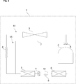
- a conventional domestic refrigerator typically includes a refrigeration circuit (14 ⁇ ) which includes a compressor (2 ⁇ ) a condenser (3 ⁇ ), a capillary tube (4 ⁇ ), a freezer evaporator (5 ⁇ ) and a fresh food evaporator (6 ⁇ ) which are serially arranged and fluidly connected to one another by respective lines for circulating a refrigerant (Fig. 1).
- the refrigerant circulating through the freezer evaporator cools a surface thereof.
- the ambient vapor inside the freezer compartment condenses on the surface of the evaporator and forms frost.
- Frost has a relatively low thermal conductivity, and blocks the air passages of the evaporator. Therefore, the cooling performance of the refrigerator reduces and an energy consumption of the refrigerator increases. Therefore, the frost must be intermittently removed.
- the hot refrigerant in the condenser is utilized for melting the frost on the freezer evaporator.
- This technique is also known as the hot gas defrost technique.
- the hot gas defrost technique the hot refrigerant in the condenser is drawn into the freezer evaporator.
- the hot gas in the freezer evaporator is circulated by the compressor while bypassing the condenser.
- a drawback of this technique is that liquid refrigerant may enter into the compressor. Thus, a life time of the compressor degrades.
- CN 2937962 discloses a refrigerator which has a refrigeration circuit and a hot gas defrost circuit.
- the refrigeration circuit includes two evaporators.
- the hot gas defrost circuit includes a bypass circuit for circulating the hot gas through the evaporators.
- An objective of the present invention is to provide a refrigerator and method for controlling the refrigerator which overcome the aforementioned problems of the prior art and improve a defrost efficiency.
- the refrigerator of the present invention has a defrost circuit which includes an additional capillary which is arranged parallel to an intermediary line which fluidly connect an output of a freezer evaporator with an input of a fresh food evaporator.
- the defrost circuit further includes an additional valve unit for respectively controlling convey of the refrigerant output from the freezer evaporator to the additional capillary and to the first intermediary line.
- the compressor is enabled to effectively compress the refrigerant which is output from the fresh food evaporator.
- the freezer evaporator receives hot refrigerant from the compressor and effectively functions like a “condenser”.
- the fresh food evaporator can effectively perform cooling as if being operated in the normal refrigeration mode.
- the refrigerant is conveyed through the intermediary line.
- the defrost circuit has an additional valve unit for preventing refrigerant from flowing back into the additional capillary of the refrigeration circuit.
- the additional valve unit avoids such flow back. Thereby, the pressurized refrigerant is completely conveyed into the freezer evaporator during the defrost mode. Consequently, the defrosting efficiency in the freezer evaporator is increased. In addition, the cooling efficiency in the fresh food evaporator is also increased.
- the refrigerator of the present invention enables cooling of the fresh food evaporator while simultaneously defrosting the freezer evaporator.
- the refrigerator of the present invention has an improved defrost efficiency.
- the overall energy efficiency of the refrigerator is improved.
- the refrigerator of the present invention prevents liquid refrigerant from entering into the compressor. Thereby, a life time of the compressor is considerably prolonged. Consequently, the maintenance requirements of the refrigerator of the present invention is low. Hence, a consumer satisfaction is also improved.
- Figure 1 - is a schematic view of a conventional refrigeration circuit.
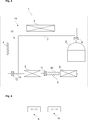
- Figure 2 - is a schematic view of a refrigeration circuit and a defrost circuit according to an embodiment of the present invention.
- Figure 3 - is a schematic view of a refrigeration circuit and a defrost circuit according to another embodiment of the present invention.
- Figure 4 - is a schematic perspective front view showing the outputs of a first valve unit and a second valve unit according to another embodiment of the present invention.
- the refrigerator (1) comprises a refrigeration circuit (14) and a defrost circuit (15).
- the refrigeration circuit (14) includes a compressor (2), a condenser (3), a first capillary (4), a freezer evaporator (5) and a fresh food evaporator (6) which are serially arranged and fluidly connected to one another by respective lines for circulating a refrigerant.
- the defrost circuit (15) includes a bypass line (7) which fluidly connects the output of the compressor (2) with the input of the freezer evaporator (5) and a first valve unit (8) for respectively controlling a convey of the refrigerant output from the compressor (2) to an input of the condenser (3) and to the bypass line (7) (Figs. 2 and 3).
- the refrigerator (1) further includes a control unit (not shown) for controlling the refrigeration circuit (14) and the defrost circuit (15).
- the control unit has a defrost mode and a normal refrigeration mode.
- the defrost circuit (15) further includes a second capillary (9) which is arranged parallel to a first intermediary line (10) which fluidly connect the output of the freezer evaporator (5) with the input of the fresh food evaporator (6) (Figs. 2 and 3).
- the defrost circuit (15) further includes a second valve unit (11) for respectively controlling convey of the refrigerant output from the freezer evaporator (5) to the second capillary (9) and to the first intermediary line (10) (Figs. 2 and 3).
- the compressor (2) is enabled to compress the refrigerant which is output by the fresh food evaporator (6).
- the freezer evaporator (5) receives hot refrigerant and effectively functions like a “condenser”.
- the fresh food evaporator (6) performs cooling as in the normal refrigeration mode.
- the pressure-drop across the second capillary (9) during the defrost mode is smaller than the pressure-drop across the first capillary (4) during the normal refrigeration mode.
- the first capillary (4) and the second capillary (9) used in the present invention are throttling devices.
- an expansion valve, a needle valve or the like can be used for achieving pressure differences in the refrigeration circuit (14)/defrost circuit (15) of the present invention.
- the refrigerator (1) has a first temperature sensor (not shown) for detecting a temperature of the refrigerant at an output of the condenser (3) and for outputting a signal to the control unit.
- the signal is indicative of the detected temperature.
- a rate of temperature change of the refrigerant at an output side of the condenser (3) is monitored. Thereby, a transient phase and a steady state phase of the defrost mode can be discriminated.
- the refrigerator (1) has a second temperature sensor (not shown) for detecting a temperature of a surface of the freezer evaporator (5) and for outputting a signal to the control unit.
- the signal is indicative of the detected temperature.
- a temperature of the surface of the freezer evaporator (5) is monitored. Thereby, the melting process can be better watched.
- the refrigerator (1) has a timer (not shown) for detecting an elapsed time and for outputting a signal to the control unit.
- the signal is indicative of the elapsed time.
- the first valve unit (8) is configured by a three-way valve which includes an input, a first output and a second output (Fig. 4).
- the input of the first valve unit (8) is fluidly connected to the output of the compressor (2), the first output is fluidly connected to the input of the condenser (3), and the second output is fluidly connected to the bypass line (7) (Figs. 2 and 3).
- the use of a three-way valve simplifies control of the defrost circuit (15).
- the second valve unit (11) is configured by a three-way valve which includes an input, a first output and a second output (Fig. 4).
- the input of the second valve unit (11) is fluidly connected to the output of the freezer evaporator (5), the first output is fluidly connected to the first intermediary line (10), and the second output is fluidly connected to the second capillary (9) (Figs. 2 and 3).
- the defrost circuit (15) has a third valve unit (12) for preventing refrigerant from flowing back into the first capillary (4) (Fig. 3).
- the compressor (2) starts to effectively compress the refrigerant which is output by the fresh food evaporator (6)
- the pressurized refrigerant which is output the bypass line (7) also tends to flow back into the first capillary (4).
- third valve unit (12) the flow back can be avoided. Thereby, the pressurized refrigerant can be completely conveyed into the freezer evaporator (5) during the defrost mode.
- the third valve unit (12) includes an input and an output (Fig. 3).
- the input of the third valve unit (12) is fluidly connected to an output of the first capillary (4) (Fig. 3).
- the output of the third valve unit (12) is connected to a second intermediary line (13) which is fluidly connected to the output of the bypass line (7) and the input of the freezer evaporator (5) (Fig. 3).
- the method for controlling the refrigerator (1) of the present invention comprises the steps of: initiating the defrost mode; activating the compressor (2); conveying the output of the compressor (2) to an input of the freezer evaporator (5) by inhibiting a convey of the refrigerant output from the compressor (2) to the condenser (3) and by allowing a convey of the refrigerant output from the compressor (2) to the bypass line (7); and conveying the refrigerant output from the freezer evaporator (5) to the fresh food evaporator (6) by inhibiting convey of the refrigerant output from the freezer evaporator (5) to the first intermediary line (10) and by allowing convey of the refrigerant output from the freezer evaporator (5) to the second capillary (9) (Figs. 2 and 3).
- the step of allowing the convey of the refrigerant output from the compressor (2) to the bypass line (7) includes a step of determining a rate of temperature change of the refrigerant at an output of the condenser (3).
- the refrigerant is inhibited to be conveyed to the bypass line (7) when said rate of temperature change is above a threshold rate and the refrigerant is started being conveyed to the bypass line (7) when said rate of temperature change drops below a threshold rate.
- the rate of temperature change of the refrigerant at the output of the condenser (3) is above a threshold rate at the initial phase of the defrost mode. Once an equilibrium state is reached in the defrost mode such that the rate of temperature change of the refrigerant at the output of the condenser (3) drops below a threshold rate, the bypass line (7) is opened for circulating the refrigerant through the defrost circuit (15).
- the refrigerant is not inhibited to be conveyed to the bypass line (7) at an initial phase of the defrost mode where the rate of temperature change of the refrigerant at the output of the condenser (3) exceeds the threshold rate.
- the step of conveying the refrigerant output from the freezer evaporator (5) to an input of the fresh food evaporator (6) includes a step of determining a rate of temperature change of the refrigerant at an output of the condenser (3).
- the refrigerant output from the freezer evaporator (5) is conveyed to an input of the fresh food evaporator (6) only via the first intermediary line (10) when said rate of temperature change is above a threshold rate and the refrigerant output from the freezer evaporator (5) is started being conveyed to an input of the fresh food evaporator (6) only via the second capillary (9) when said rate of temperature change reduces below a threshold rate.
- the refrigerant is conveyed via the first intermediary line (10).
- the refrigerant is conveyed only via the second capillary (9).
- the method for controlling the refrigerator (1) further comprises a step of terminating circulation of the refrigerant when the temperature of the surface of the freezer evaporator (5) has reached 0°C. Thereby, a melting process is set into progress.
- the method for controlling the refrigerator (1) further comprises a step of inhibiting start of the normal refrigeration mode for a predetermined duration after terminating circulation of the refrigerant. Thus, melting of the frost is waited for said predetermined duration.
- the method for controlling the refrigerator (1) further comprises a step of inhibiting refrigerant to be conveyed to the first intermediary line (10) and the second capillary (9) for said predetermined duration.
- the melting process is safeguarded.
- the step of conveying the refrigerant output from the freezer evaporator (5) to the fresh food evaporator (9) includes a step of preventing the refrigerant output from the bypass line (7) from flowing back into the first capillary (4).
- a convey of the refrigerant back into the first capillary (4) is inhibited when the rate of temperature change of the refrigerant at an output of the condenser (3) drops below a threshold rate.
- the hot refrigerant is completely conveyed into the freezer evaporator (5). Consequently, the defrosting efficiency in the freezer evaporator is increased.
- the cooling efficiency in the fresh food evaporator (6) is also increased.
- control unit of the refrigerator (1) of the present invention is configured to execute the steps defined in the above control method of the present invention.
- the control unit is provided with corresponding computer executable codes which are stored in a non-volatile memory.
- the refrigerator of the present invention enables substantially uninterrupted cooling of the fresh food evaporator while simultaneously defrosting the freezer evaporator. Thereby an overall energy efficiency of the refrigerator is improved.
- the refrigerator of the present invention prevents liquid refrigerant from entering the compressor. Thereby, a life time of the compressor is considerably prolonged.
Landscapes
- Engineering & Computer Science (AREA)
- Physics & Mathematics (AREA)
- Mechanical Engineering (AREA)
- Thermal Sciences (AREA)
- General Engineering & Computer Science (AREA)
- Chemical & Material Sciences (AREA)
- Combustion & Propulsion (AREA)
- Defrosting Systems (AREA)
Abstract
The present invention relates to a refrigerator comprising: a refrigeration circuit (14) which includes: a compressor (2), a condenser (3), a first capillary (4), a freezer evaporator (5) and a fresh food evaporator (6) which are serially arranged and fluidly connected to one another by respective lines for circulating a refrigerant, a defrost circuit (15) which includes a bypass line (7) which fluidly connects the output of the compressor (2) with the input of the freezer evaporator (5), and a first valve unit (8) for respectively controlling a convey of the refrigerant output from the compressor (2) to an input of the condenser (3) and to the bypass line (7) and a control unit for controlling the refrigeration circuit (14) and the defrost circuit (15), wherein the control unit has a defrost mode and a normal refrigeration mode.
Description
The present invention relates to a method of controlling a refrigerator, in particular a domestic refrigerator which includes one freezer evaporator and one fresh food evaporator. The present invention particularly relates a method of controlling the refrigerator to defrost the freezer evaporator.
A conventional domestic refrigerator typically includes a refrigeration circuit (14´) which includes a compressor (2´) a condenser (3´), a capillary tube (4´), a freezer evaporator (5´) and a fresh food evaporator (6´) which are serially arranged and fluidly connected to one another by respective lines for circulating a refrigerant (Fig. 1). The refrigerant circulating through the freezer evaporator cools a surface thereof. The ambient vapor inside the freezer compartment condenses on the surface of the evaporator and forms frost. Frost has a relatively low thermal conductivity, and blocks the air passages of the evaporator. Therefore, the cooling performance of the refrigerator reduces and an energy consumption of the refrigerator increases. Therefore, the frost must be intermittently removed.
Several techniques have been developed to remove the frost accumulated on the surface of the freezer evaporator. In a commonly known technique, a heater wire is utilized to melt the frost. The heater wire is arranged in the vicinity of the freezer evaporator. According to this technique, the normal refrigeration cycle is stopped and the heater wire is energized to melt the frost. A drawback of this technique is that an energizing of the electric wire incurs extra energy consumption. Moreover, the provision of the electric wire and the installation thereof increases the cost of the refrigerator.
In another commonly known technique, the hot refrigerant in the condenser is utilized for melting the frost on the freezer evaporator. This technique is also known as the hot gas defrost technique. According to the hot gas defrost technique, the hot refrigerant in the condenser is drawn into the freezer evaporator. The hot gas in the freezer evaporator is circulated by the compressor while bypassing the condenser. A drawback of this technique is that liquid refrigerant may enter into the compressor. Thus, a life time of the compressor degrades.
CN 2937962 (Y) discloses a refrigerator which has a refrigeration circuit and a hot gas defrost circuit. The refrigeration circuit includes two evaporators. The hot gas defrost circuit includes a bypass circuit for circulating the hot gas through the evaporators.
An objective of the present invention is to provide a refrigerator and method for controlling the refrigerator which overcome the aforementioned problems of the prior art and improve a defrost efficiency.
This objective has been achieved by the refrigerator according to the present invention as defined in claim 1, and the method of controlling the refrigerator according to the present invention as defined in claim 9. Further achievements have been attained by the subject-matters respectively defined in the dependent claims.
The refrigerator of the present invention has a defrost circuit which includes an additional capillary which is arranged parallel to an intermediary line which fluidly connect an output of a freezer evaporator with an input of a fresh food evaporator. The defrost circuit further includes an additional valve unit for respectively controlling convey of the refrigerant output from the freezer evaporator to the additional capillary and to the first intermediary line. In the defrost mode, the refrigerant is conveyed through the additional capillary which throttles the convey of the refrigerant. Thereby, the compressor is enabled to effectively compress the refrigerant which is output from the fresh food evaporator. The freezer evaporator receives hot refrigerant from the compressor and effectively functions like a “condenser”. Thus, during the defrost mode, the fresh food evaporator can effectively perform cooling as if being operated in the normal refrigeration mode. In the normal refrigeration mode, the refrigerant is conveyed through the intermediary line.
In an embodiment, the defrost circuit has an additional valve unit for preventing refrigerant from flowing back into the additional capillary of the refrigeration circuit. During the defrost mode, as the compressor starts to effectively compress the refrigerant which is output from the fresh food evaporator, the pressurized refrigerant which is output from the bypass line also tends to flow back into the capillary of the refrigeration circuit. The additional valve unit avoids such flow back. Thereby, the pressurized refrigerant is completely conveyed into the freezer evaporator during the defrost mode. Consequently, the defrosting efficiency in the freezer evaporator is increased. In addition, the cooling efficiency in the fresh food evaporator is also increased.
The refrigerator of the present invention enables cooling of the fresh food evaporator while simultaneously defrosting the freezer evaporator. Thus, the refrigerator of the present invention has an improved defrost efficiency. Moreover, the overall energy efficiency of the refrigerator is improved. In addition, the refrigerator of the present invention prevents liquid refrigerant from entering into the compressor. Thereby, a life time of the compressor is considerably prolonged. Consequently, the maintenance requirements of the refrigerator of the present invention is low. Hence, a consumer satisfaction is also improved.
Additional advantages of the control method according to the present invention and the refrigerator according to the present invention will become apparent with the detailed description of the embodiments with reference to the accompanying drawings in which:
Figure 1 - is a schematic view of a conventional refrigeration circuit.
Figure 2 - is a schematic view of a refrigeration circuit and a defrost circuit according to an embodiment of the present invention.
Figure 3 - is a schematic view of a refrigeration circuit and a defrost circuit according to another embodiment of the present invention.
Figure 4 - is a schematic perspective front view showing the outputs of a first valve unit and a second valve unit according to another embodiment of the present invention.
The reference signs appearing on the drawings relate to the following technical features.
- Refrigerator
- Compressor
- Condenser
- First capillary
- Freezer evaporator
- Fresh food evaporator
- Bypass line
- First valve unit
- Second capillary
- First intermediary line
- Second valve unit
- Third valve unit
- Second intermediary line
- Refrigeration circuit
- Defrost circuit
The refrigerator (1) comprises a refrigeration circuit (14) and a defrost circuit (15). The refrigeration circuit (14) includes a compressor (2), a condenser (3), a first capillary (4), a freezer evaporator (5) and a fresh food evaporator (6) which are serially arranged and fluidly connected to one another by respective lines for circulating a refrigerant. The defrost circuit (15) includes a bypass line (7) which fluidly connects the output of the compressor (2) with the input of the freezer evaporator (5) and a first valve unit (8) for respectively controlling a convey of the refrigerant output from the compressor (2) to an input of the condenser (3) and to the bypass line (7) (Figs. 2 and 3). The refrigerator (1) further includes a control unit (not shown) for controlling the refrigeration circuit (14) and the defrost circuit (15). The control unit has a defrost mode and a normal refrigeration mode.
In the refrigerator (1) of the present invention, the defrost circuit (15) further includes a second capillary (9) which is arranged parallel to a first intermediary line (10) which fluidly connect the output of the freezer evaporator (5) with the input of the fresh food evaporator (6) (Figs. 2 and 3). The defrost circuit (15) further includes a second valve unit (11) for respectively controlling convey of the refrigerant output from the freezer evaporator (5) to the second capillary (9) and to the first intermediary line (10) (Figs. 2 and 3).
By virtue of the second capillary (9), conveying of refrigerant is throttled during the defrost mode. Thereby, the compressor (2) is enabled to compress the refrigerant which is output by the fresh food evaporator (6). The freezer evaporator (5) receives hot refrigerant and effectively functions like a “condenser”. Thus, during the defrost mode, the fresh food evaporator (6) performs cooling as in the normal refrigeration mode. The pressure-drop across the second capillary (9) during the defrost mode is smaller than the pressure-drop across the first capillary (4) during the normal refrigeration mode. The first capillary (4) and the second capillary (9) used in the present invention are throttling devices. Alternatively, an expansion valve, a needle valve or the like can be used for achieving pressure differences in the refrigeration circuit (14)/defrost circuit (15) of the present invention.
In an embodiment, the refrigerator (1) has a first temperature sensor (not shown) for detecting a temperature of the refrigerant at an output of the condenser (3) and for outputting a signal to the control unit. The signal is indicative of the detected temperature. By virtue of the temperature sensor, a rate of temperature change of the refrigerant at an output side of the condenser (3) is monitored. Thereby, a transient phase and a steady state phase of the defrost mode can be discriminated.
In another embodiment, the refrigerator (1) has a second temperature sensor (not shown) for detecting a temperature of a surface of the freezer evaporator (5) and for outputting a signal to the control unit. The signal is indicative of the detected temperature. By virtue of the temperature sensor, a temperature of the surface of the freezer evaporator (5) is monitored. Thereby, the melting process can be better watched.
In another embodiment, the refrigerator (1) has a timer (not shown) for detecting an elapsed time and for outputting a signal to the control unit. The signal is indicative of the elapsed time. By virtue of the timer, a duration for allowing the frost on the freezer evaporator (5) to melt can be monitored.
In another embodiment, the first valve unit (8) is configured by a three-way valve which includes an input, a first output and a second output (Fig. 4). The input of the first valve unit (8) is fluidly connected to the output of the compressor (2), the first output is fluidly connected to the input of the condenser (3), and the second output is fluidly connected to the bypass line (7) (Figs. 2 and 3). The use of a three-way valve simplifies control of the defrost circuit (15).
In another embodiment, the second valve unit (11) is configured by a three-way valve which includes an input, a first output and a second output (Fig. 4). The input of the second valve unit (11) is fluidly connected to the output of the freezer evaporator (5), the first output is fluidly connected to the first intermediary line (10), and the second output is fluidly connected to the second capillary (9) (Figs. 2 and 3).
In another embodiment, the defrost circuit (15) has a third valve unit (12) for preventing refrigerant from flowing back into the first capillary (4) (Fig. 3). As the compressor (2) starts to effectively compress the refrigerant which is output by the fresh food evaporator (6), the pressurized refrigerant which is output the bypass line (7) also tends to flow back into the first capillary (4). By virtue of third valve unit (12), the flow back can be avoided. Thereby, the pressurized refrigerant can be completely conveyed into the freezer evaporator (5) during the defrost mode.
In another embodiment, the third valve unit (12) includes an input and an output (Fig. 3). The input of the third valve unit (12) is fluidly connected to an output of the first capillary (4) (Fig. 3). The output of the third valve unit (12) is connected to a second intermediary line (13) which is fluidly connected to the output of the bypass line (7) and the input of the freezer evaporator (5) (Fig. 3).
The method for controlling the refrigerator (1) of the present invention, comprises the steps of: initiating the defrost mode; activating the compressor (2); conveying the output of the compressor (2) to an input of the freezer evaporator (5) by inhibiting a convey of the refrigerant output from the compressor (2) to the condenser (3) and by allowing a convey of the refrigerant output from the compressor (2) to the bypass line (7); and conveying the refrigerant output from the freezer evaporator (5) to the fresh food evaporator (6) by inhibiting convey of the refrigerant output from the freezer evaporator (5) to the first intermediary line (10) and by allowing convey of the refrigerant output from the freezer evaporator (5) to the second capillary (9) (Figs. 2 and 3).
In an embodiment, the step of allowing the convey of the refrigerant output from the compressor (2) to the bypass line (7) includes a step of determining a rate of temperature change of the refrigerant at an output of the condenser (3). In this embodiment, the refrigerant is inhibited to be conveyed to the bypass line (7) when said rate of temperature change is above a threshold rate and the refrigerant is started being conveyed to the bypass line (7) when said rate of temperature change drops below a threshold rate. Thus, at the initial phase of the defrost mode the hot refrigerant in the condenser (3) is drawn into the freezer evaporator (5) by the compressor (2). The rate of temperature change of the refrigerant at the output of the condenser (3) is above a threshold rate at the initial phase of the defrost mode. Once an equilibrium state is reached in the defrost mode such that the rate of temperature change of the refrigerant at the output of the condenser (3) drops below a threshold rate, the bypass line (7) is opened for circulating the refrigerant through the defrost circuit (15).
In an alternative embodiment, the refrigerant is not inhibited to be conveyed to the bypass line (7) at an initial phase of the defrost mode where the rate of temperature change of the refrigerant at the output of the condenser (3) exceeds the threshold rate.
In another embodiment, the step of conveying the refrigerant output from the freezer evaporator (5) to an input of the fresh food evaporator (6) includes a step of determining a rate of temperature change of the refrigerant at an output of the condenser (3). In this embodiment, the refrigerant output from the freezer evaporator (5) is conveyed to an input of the fresh food evaporator (6) only via the first intermediary line (10) when said rate of temperature change is above a threshold rate and the refrigerant output from the freezer evaporator (5) is started being conveyed to an input of the fresh food evaporator (6) only via the second capillary (9) when said rate of temperature change reduces below a threshold rate. Thus, at the initial phase of the defrost mode where the rate of temperature change is above a threshold rate, the refrigerant is conveyed via the first intermediary line (10). Once a steady state phase is reached in the defrost mode the refrigerant is conveyed only via the second capillary (9). Thereby, the surface of fresh food evaporator starts to effectively cool as if in the normal refrigeration mode.
In another embodiment, the method for controlling the refrigerator (1) further comprises a step of terminating circulation of the refrigerant when the temperature of the surface of the freezer evaporator (5) has reached 0°C. Thereby, a melting process is set into progress.
In another embodiment, the method for controlling the refrigerator (1) further comprises a step of inhibiting start of the normal refrigeration mode for a predetermined duration after terminating circulation of the refrigerant. Thus, melting of the frost is waited for said predetermined duration.
In another embodiment, the method for controlling the refrigerator (1) further comprises a step of inhibiting refrigerant to be conveyed to the first intermediary line (10) and the second capillary (9) for said predetermined duration. Thereby, the melting process is safeguarded.
In another embodiment, the step of conveying the refrigerant output from the freezer evaporator (5) to the fresh food evaporator (9) includes a step of preventing the refrigerant output from the bypass line (7) from flowing back into the first capillary (4). In this embodiment, a convey of the refrigerant back into the first capillary (4) is inhibited when the rate of temperature change of the refrigerant at an output of the condenser (3) drops below a threshold rate. Thereby, the hot refrigerant is completely conveyed into the freezer evaporator (5). Consequently, the defrosting efficiency in the freezer evaporator is increased. In addition, the cooling efficiency in the fresh food evaporator (6) is also increased.
In another embodiment, the control unit of the refrigerator (1) of the present invention is configured to execute the steps defined in the above control method of the present invention. In this embodiment, the control unit is provided with corresponding computer executable codes which are stored in a non-volatile memory.
The refrigerator of the present invention enables substantially uninterrupted cooling of the fresh food evaporator while simultaneously defrosting the freezer evaporator. Thereby an overall energy efficiency of the refrigerator is improved. In addition, the refrigerator of the present invention prevents liquid refrigerant from entering the compressor. Thereby, a life time of the compressor is considerably prolonged.
Claims (15)
- A refrigerator (1) comprising a refrigeration circuit (14) which includes a compressor (2), a condenser (3), a first capillary (4), a freezer evaporator (5) and a fresh food evaporator (6) which are serially arranged and fluidly connected to one another by respective lines for circulating a refrigerant, a defrost circuit (15) which includes a bypass line (7) which fluidly connects the output of the compressor (2) with the input of the freezer evaporator (5) and a first valve unit (8) for respectively controlling a convey of the refrigerant output from the compressor (2) to an input of the condenser (3) and to the bypass line (7) and a control unit for controlling the refrigeration circuit (14) and the defrost circuit (15), wherein the control unit has a defrost mode and a normal refrigeration mode, characterized in that the defrost circuit (15) further including a second capillary (9) which is arranged parallel to a first intermediary line (10) which fluidly connect the output of the freezer evaporator (5) with the input of the fresh food evaporator (6) and a second valve unit (11) for respectively controlling convey of the refrigerant output from the freezer evaporator (5) to the second capillary (9) and to the first intermediary line (10).
- The refrigerator (1) according to claim 1, characterized in that a first temperature sensor for detecting a temperature of the refrigerant at an output of the condenser (3) and for outputting a signal to the control unit, wherein the signal is indicative of the detected temperature.
- The refrigerator (1) according to claim 1 or 2, characterized in that a second temperature sensor for detecting a temperature of a surface of the freezer evaporator (5) and for outputting a signal to the control unit, wherein the signal is indicative of the detected temperature.
- The refrigerator (1) according to any one of claims 1 to 3, characterized in that a timer for detecting an elapsed time and for outputting a signal to the control unit, wherein the signal is indicative of the elapsed time.
- The refrigerator (1) according to any one of claims 1 to 4, characterized in that the first valve unit (8) is configured by a three-way valve which includes an input, a first output and a second output, wherein the input is fluidly connected to the output of the compressor (2), the first output is fluidly connected to the input of the condenser (3), and the second output is fluidly connected to the bypass line (7).
- The refrigerator (1) according to any one of claims 1 to 5, characterized in that the second valve unit (11) is configured by a three-way valve which includes an input, a first output and a second output, wherein the input is fluidly connected to the output of the freezer evaporator (5), the first output is fluidly connected to the first intermediary line (10) and the second output is fluidly connected to the second capillary (9).
- The refrigerator (1) according to any one of claims 1 to 6, characterized in that the defrost circuit (15) further includes a third valve unit (12) for preventing refrigerant from flowing back into the first capillary (4).
- The refrigerator (1) according to claim 7, characterized in that the third valve unit (12) includes an input and an output, wherein said input is fluidly connected to an output of the first capillary (4), and said output is connected to a second intermediary line (13) which is fluidly connected to the output of the bypass line (7) and the input of the freezer evaporator (5).
- A method for controlling a refrigerator (1) as defined in any one of claims 1 to 8,comprising the steps of:- initiating the defrost mode,- activating the compressor (2),- conveying the output of the compressor (2) to an input of the freezer evaporator (5) by inhibiting convey of the refrigerant output from the compressor (2) to the condenser (3) and by allowing a convey of the refrigerant output from the compressor (2) to the bypass line (7) and- conveying the refrigerant output from the freezer evaporator (5) to the fresh food evaporator (6) by inhibiting convey of the refrigerant output from the freezer evaporator (5) to the first intermediary line (10) and by allowing convey of the refrigerant output from the freezer evaporator (5) to the second capillary (9).
- The method according to claim 9, further comprising the step of:- allowing the convey of the refrigerant output from the compressor (2) to the bypass line (7) includes a step of determining a rate of temperature change of the refrigerant at an output of the condenser (3), wherein the refrigerant is inhibited to be conveyed to the bypass line (7) when said rate of temperature change is above a threshold rate and wherein the refrigerant is started being conveyed to the bypass line (7) when said rate of temperature change drops below a threshold rate.
- The method according to claim 9 or 10, further comprising the step of:- conveying the refrigerant output from the freezer evaporator (5) to an input of the fresh food evaporator (6) includes a step of determining a rate of temperature change of the refrigerant at an output of the condenser (3), wherein the refrigerant output from the freezer evaporator (5) is conveyed to an input of the fresh food evaporator (6) only via the first intermediary line (10) when said rate of temperature change is above a threshold rate and wherein the refrigerant output from the freezer evaporator (5) is started being conveyed to an input of the fresh food evaporator (6) only via the second capillary (9) when said rate of temperature change reduces below a threshold rate.
- The method according to any one of claims 9 to 11, further comprising the step of:- terminating circulation of the refrigerant when the temperature of the surface of the freezer evaporator (5) has reached to a predetermined temperature above 0°C.
- The method according to claim 12, further comprising the step of:- inhibiting start of the normal refrigeration mode for a predetermined duration after terminating circulation of the refrigerant.
- The method according to claim 13, further comprising the step of:- inhibiting refrigerant to be conveyed to the first intermediary line (10) and the second capillary (9) for said predetermined duration.
- The method according to any one of claims 9 to 14, further comprising the step of:- conveying the refrigerant output from the freezer evaporator (5) to the fresh food evaporator (6) includes a step of preventing the refrigerant output from the bypass line (7) from flowing back into the first capillary (4), wherein a convey of the refrigerant back into the first capillary (4) is inhibited when a rate of temperature change of the refrigerant at an output of the condenser (3) drops below a threshold rate.
Priority Applications (1)
| Application Number | Priority Date | Filing Date | Title |
|---|---|---|---|
| PCT/EP2013/070357 WO2015043678A1 (en) | 2013-09-30 | 2013-09-30 | Refrigerator with an improved defrost circuit and method of controlling the refrigerator |
Applications Claiming Priority (1)
| Application Number | Priority Date | Filing Date | Title |
|---|---|---|---|
| PCT/EP2013/070357 WO2015043678A1 (en) | 2013-09-30 | 2013-09-30 | Refrigerator with an improved defrost circuit and method of controlling the refrigerator |
Publications (1)
| Publication Number | Publication Date |
|---|---|
| WO2015043678A1 true WO2015043678A1 (en) | 2015-04-02 |
Family
ID=49303966
Family Applications (1)
| Application Number | Title | Priority Date | Filing Date |
|---|---|---|---|
| PCT/EP2013/070357 Ceased WO2015043678A1 (en) | 2013-09-30 | 2013-09-30 | Refrigerator with an improved defrost circuit and method of controlling the refrigerator |
Country Status (1)
| Country | Link |
|---|---|
| WO (1) | WO2015043678A1 (en) |
Cited By (6)
| Publication number | Priority date | Publication date | Assignee | Title |
|---|---|---|---|---|
| CN114593550A (en) * | 2022-03-23 | 2022-06-07 | 创维电器股份有限公司 | A kind of control system and control method of automatic frost of direct cooling refrigerator |
| WO2022143413A1 (en) * | 2020-12-28 | 2022-07-07 | 重庆海尔制冷电器有限公司 | Refrigerator |
| US20220381495A1 (en) * | 2020-06-30 | 2022-12-01 | Trane International Inc. | Dynamic liquid receiver and control strategy |
| CN115540407A (en) * | 2021-06-29 | 2022-12-30 | 青岛海尔电冰箱有限公司 | Refrigeration system for a refrigerator-freezer and a refrigerator-freezer |
| US12140352B2 (en) | 2020-06-30 | 2024-11-12 | Trane International Inc. | Superheating control for heating, ventilation, air conditioning and refrigeration (HVACR) system including a dynamic receiver |
| US12693062B2 (en) | 2024-03-25 | 2026-07-28 | Haier Us Appliance Solutions, Inc. | Refrigerator appliance having a dual-flow sealed system and methods of operating the same |
Citations (6)
| Publication number | Priority date | Publication date | Assignee | Title |
|---|---|---|---|---|
| US2667757A (en) * | 1952-02-07 | 1954-02-02 | Philco Corp | Plural temperature refrigeration system |
| FR1309008A (en) * | 1961-12-29 | 1962-11-09 | Sterne & Company Ltd L | Refrigeration appliance |
| FR2198103A1 (en) * | 1972-07-25 | 1974-03-29 | Naniwa Sangyo Co Ltd | |
| US3822564A (en) * | 1972-08-01 | 1974-07-09 | Naniwa Sangyo Co Ltd | Combination type refrigerator |
| FR2378244A1 (en) * | 1977-01-24 | 1978-08-18 | Electrolux Ab | Refrigeration appliance with compressor operation - has several evaporators deiced on normal operation without influencing other evaporators |
| US20110011109A1 (en) * | 2009-07-16 | 2011-01-20 | Alexander Rafalovich | Dual evaporator defrost system for an appliance |
-
2013
- 2013-09-30 WO PCT/EP2013/070357 patent/WO2015043678A1/en not_active Ceased
Patent Citations (6)
| Publication number | Priority date | Publication date | Assignee | Title |
|---|---|---|---|---|
| US2667757A (en) * | 1952-02-07 | 1954-02-02 | Philco Corp | Plural temperature refrigeration system |
| FR1309008A (en) * | 1961-12-29 | 1962-11-09 | Sterne & Company Ltd L | Refrigeration appliance |
| FR2198103A1 (en) * | 1972-07-25 | 1974-03-29 | Naniwa Sangyo Co Ltd | |
| US3822564A (en) * | 1972-08-01 | 1974-07-09 | Naniwa Sangyo Co Ltd | Combination type refrigerator |
| FR2378244A1 (en) * | 1977-01-24 | 1978-08-18 | Electrolux Ab | Refrigeration appliance with compressor operation - has several evaporators deiced on normal operation without influencing other evaporators |
| US20110011109A1 (en) * | 2009-07-16 | 2011-01-20 | Alexander Rafalovich | Dual evaporator defrost system for an appliance |
Cited By (11)
| Publication number | Priority date | Publication date | Assignee | Title |
|---|---|---|---|---|
| US20220381495A1 (en) * | 2020-06-30 | 2022-12-01 | Trane International Inc. | Dynamic liquid receiver and control strategy |
| US11885545B2 (en) * | 2020-06-30 | 2024-01-30 | Trane International Inc. | Dynamic liquid receiver and control strategy |
| US12140352B2 (en) | 2020-06-30 | 2024-11-12 | Trane International Inc. | Superheating control for heating, ventilation, air conditioning and refrigeration (HVACR) system including a dynamic receiver |
| WO2022143413A1 (en) * | 2020-12-28 | 2022-07-07 | 重庆海尔制冷电器有限公司 | Refrigerator |
| CN116724205A (en) * | 2020-12-28 | 2023-09-08 | 重庆海尔制冷电器有限公司 | refrigerator |
| CN115540407A (en) * | 2021-06-29 | 2022-12-30 | 青岛海尔电冰箱有限公司 | Refrigeration system for a refrigerator-freezer and a refrigerator-freezer |
| WO2023273709A1 (en) * | 2021-06-29 | 2023-01-05 | 青岛海尔电冰箱有限公司 | Refrigerating system for refrigerating and freezing device and refrigerating and freezing device |
| EP4365516A4 (en) * | 2021-06-29 | 2024-10-16 | Qingdao Haier Refrigerator Co., Ltd | COOLING SYSTEM FOR REFRIGERATOR AND FREEZER AS WELL AS REFRIGERATOR AND FREEZER |
| US12578132B2 (en) | 2021-06-29 | 2026-03-17 | Qingdao Haier Refrigerator Co., Ltd. | Refrigeration system and refrigerating appliance |
| CN114593550A (en) * | 2022-03-23 | 2022-06-07 | 创维电器股份有限公司 | A kind of control system and control method of automatic frost of direct cooling refrigerator |
| US12693062B2 (en) | 2024-03-25 | 2026-07-28 | Haier Us Appliance Solutions, Inc. | Refrigerator appliance having a dual-flow sealed system and methods of operating the same |
Similar Documents
| Publication | Publication Date | Title |
|---|---|---|
| JP5575192B2 (en) | Dual refrigeration equipment | |
| CN104613688B (en) | The hot gas defrosting system of a kind of refrigerator and control method thereof | |
| EP2142863B1 (en) | Control method of refrigerator | |
| CA2108342C (en) | Method for sequentially operating refrigeration system with multiple evaporators | |
| WO2015062662A1 (en) | Refrigerator with an improved defrost circuit and method for controlling the refrigerator | |
| CN105091437B (en) | A kind of control method of the automatic defrosting system of wind cooling refrigerator | |
| CN101512253B (en) | Refrigeration machine and operating method for it | |
| US20140123690A1 (en) | Method for improving efficiency of a refrigerator appliance during a defrost cycle | |
| EP3540343B1 (en) | Refrigerator and control method of refrigerator | |
| CN104329872A (en) | Refrigerator evaporator defrosting method | |
| CN107543351B (en) | Refrigerator and control method thereof | |
| CN106016920A (en) | Defrosting energy consumption control method and system for double-system refrigerator as well as refrigerator | |
| CN1333224C (en) | Refrigerator | |
| KR20060113366A (en) | Refrigerator | |
| JP2017190881A (en) | refrigerator | |
| KR101408771B1 (en) | Refrigerator defrosting method | |
| CN110285616B (en) | refrigerator control method | |
| KR20090119092A (en) | Defrosting apparatus and defrosting method for maintaining the constant temperature of the refrigerator | |
| WO2011154388A2 (en) | A cooling device with two compartments | |
| CN111148954A (en) | Control method and device for food storage equipment, storage medium | |
| JP4333586B2 (en) | Refrigeration cycle apparatus and control method thereof | |
| JP2005337677A (en) | Refrigerator | |
| CN106152675A (en) | Defrosting method, defrosting control system and refrigerating appliance for refrigerating appliance | |
| JP2002267295A (en) | refrigerator | |
| CN119687636B (en) | Dual-system refrigerator refrigeration system and control method thereof |
Legal Events
| Date | Code | Title | Description |
|---|---|---|---|
| 121 | Ep: the epo has been informed by wipo that ep was designated in this application |
Ref document number: 13773216 Country of ref document: EP Kind code of ref document: A1 |
|
| WWE | Wipo information: entry into national phase |
Ref document number: 2016/03799 Country of ref document: TR |
|
| NENP | Non-entry into the national phase |
Ref country code: DE |
|
| 122 | Ep: pct application non-entry in european phase |
Ref document number: 13773216 Country of ref document: EP Kind code of ref document: A1 |