WO2015037181A1 - Charging for mtc small data transmission and trigger at mtc-iwf - Google Patents
Charging for mtc small data transmission and trigger at mtc-iwf Download PDFInfo
- Publication number
- WO2015037181A1 WO2015037181A1 PCT/JP2014/004073 JP2014004073W WO2015037181A1 WO 2015037181 A1 WO2015037181 A1 WO 2015037181A1 JP 2014004073 W JP2014004073 W JP 2014004073W WO 2015037181 A1 WO2015037181 A1 WO 2015037181A1
- Authority
- WO
- WIPO (PCT)
- Prior art keywords
- messages
- mtc
- message
- scs
- cdr
- Prior art date
Links
Images

Classifications
-
- H—ELECTRICITY
- H04—ELECTRIC COMMUNICATION TECHNIQUE
- H04W—WIRELESS COMMUNICATION NETWORKS
- H04W4/00—Services specially adapted for wireless communication networks; Facilities therefor
- H04W4/24—Accounting or billing
-
- H—ELECTRICITY
- H04—ELECTRIC COMMUNICATION TECHNIQUE
- H04B—TRANSMISSION
- H04B7/00—Radio transmission systems, i.e. using radiation field
- H04B7/14—Relay systems
- H04B7/15—Active relay systems
- H04B7/155—Ground-based stations
-
- H—ELECTRICITY
- H04—ELECTRIC COMMUNICATION TECHNIQUE
- H04L—TRANSMISSION OF DIGITAL INFORMATION, e.g. TELEGRAPHIC COMMUNICATION
- H04L12/00—Data switching networks
- H04L12/02—Details
- H04L12/14—Charging, metering or billing arrangements for data wireline or wireless communications
- H04L12/1403—Architecture for metering, charging or billing
-
- H—ELECTRICITY
- H04—ELECTRIC COMMUNICATION TECHNIQUE
- H04L—TRANSMISSION OF DIGITAL INFORMATION, e.g. TELEGRAPHIC COMMUNICATION
- H04L12/00—Data switching networks
- H04L12/02—Details
- H04L12/14—Charging, metering or billing arrangements for data wireline or wireless communications
- H04L12/1425—Charging, metering or billing arrangements for data wireline or wireless communications involving dedicated fields in the data packet for billing purposes
-
- H—ELECTRICITY
- H04—ELECTRIC COMMUNICATION TECHNIQUE
- H04L—TRANSMISSION OF DIGITAL INFORMATION, e.g. TELEGRAPHIC COMMUNICATION
- H04L12/00—Data switching networks
- H04L12/02—Details
- H04L12/14—Charging, metering or billing arrangements for data wireline or wireless communications
- H04L12/1432—Metric aspects
-
- H—ELECTRICITY
- H04—ELECTRIC COMMUNICATION TECHNIQUE
- H04L—TRANSMISSION OF DIGITAL INFORMATION, e.g. TELEGRAPHIC COMMUNICATION
- H04L12/00—Data switching networks
- H04L12/02—Details
- H04L12/14—Charging, metering or billing arrangements for data wireline or wireless communications
- H04L12/1453—Methods or systems for payment or settlement of the charges for data transmission involving significant interaction with the data transmission network
- H04L12/1467—Methods or systems for payment or settlement of the charges for data transmission involving significant interaction with the data transmission network involving prepayment
-
- H—ELECTRICITY
- H04—ELECTRIC COMMUNICATION TECHNIQUE
- H04M—TELEPHONIC COMMUNICATION
- H04M15/00—Arrangements for metering, time-control or time indication ; Metering, charging or billing arrangements for voice wireline or wireless communications, e.g. VoIP
- H04M15/41—Billing record details, i.e. parameters, identifiers, structure of call data record [CDR]
-
- H—ELECTRICITY
- H04—ELECTRIC COMMUNICATION TECHNIQUE
- H04M—TELEPHONIC COMMUNICATION
- H04M15/00—Arrangements for metering, time-control or time indication ; Metering, charging or billing arrangements for voice wireline or wireless communications, e.g. VoIP
- H04M15/64—On-line charging system [OCS]
-
- H—ELECTRICITY
- H04—ELECTRIC COMMUNICATION TECHNIQUE
- H04M—TELEPHONIC COMMUNICATION
- H04M15/00—Arrangements for metering, time-control or time indication ; Metering, charging or billing arrangements for voice wireline or wireless communications, e.g. VoIP
- H04M15/82—Criteria or parameters used for performing billing operations
- H04M15/8214—Data or packet based
-
- H—ELECTRICITY
- H04—ELECTRIC COMMUNICATION TECHNIQUE
- H04M—TELEPHONIC COMMUNICATION
- H04M15/00—Arrangements for metering, time-control or time indication ; Metering, charging or billing arrangements for voice wireline or wireless communications, e.g. VoIP
- H04M15/82—Criteria or parameters used for performing billing operations
- H04M15/8221—Message based
-
- H—ELECTRICITY
- H04—ELECTRIC COMMUNICATION TECHNIQUE
- H04W—WIRELESS COMMUNICATION NETWORKS
- H04W4/00—Services specially adapted for wireless communication networks; Facilities therefor
- H04W4/70—Services for machine-to-machine communication [M2M] or machine type communication [MTC]
Definitions
- the present invention relates to charging for SDT (Small Data Transmission) and device trigger in MTC (Machine-Type-Communication).
- NPL 1 3GPP TR 23.887, "Machine-Type and other Mobile Data Applications Communications Enhancements (Release 12)", V1.0.0, 2013-06, Clauses 5.1.1.3.3.1.4 and 5.2.2.3.1.1.2, pp. 23 and 76
- NPL 2 3GPP TS 32.240, "Telecommunication management; Charging management; Charging architecture and principles (Release 12)", V12.0.0, 2013-03, Clauses 4.1.1 and 4.1.2, pp. 16
- NPL 1 there are few descriptions of an MME (Mobility Management) or an MTC-IWF (MTC Inter-Working Function) generating a CDR (Charging Data Record) for SDT and MTC device trigger.
- MME Mobility Management
- MTC-IWF MTC Inter-Working Function
- NPL 2 discloses charging over user plane, but does not at all disclose the charging over the control plane.
- an exemplary object of the present invention is to provide a solution for charging SDT and MTC device trigger over control plane.
- a network node includes: relay means for relaying messages over a control plane between an MTC device and an SCS (Service Capability Server); count means for counting the number of messages successfully relayed; and generation means for generating a CDR in accordance with the counted number.
- the messages are: first messages delivered from the MTC device to the SCS, the size of the first message being equal to or smaller than a predetermined size; second messages delivered from the SCS to the MTC device, the size of the second message being equal to or smaller than the predetermined size; or trigger messages delivered from the SCS to the MTC device, the trigger message being for causing the MTC device to communicate with the SCS.
- a communication system includes: an MTC device; an SCS; and a network node that relays messages over a control plane between the MTC device and the SCS.
- the network node is configured to: count the number of messages successfully relayed; and generate a CDR in accordance with the counted number.
- the messages are: first messages delivered from the MTC device to the SCS, the size of the first message being equal to or smaller than a predetermined size; second messages delivered from the SCS to the MTC device, the size of the second message being equal to or smaller than the predetermined size; or trigger messages delivered from the SCS to the MTC device, the trigger message being for causing the MTC device to communicate with the SCS.
- a method according to third exemplary aspect of the present invention provides a method of controlling operations in a network node that relays messages over a control plane between an MTC device and an SCS.
- This method includes: counting the number of messages successfully relayed; and generating a CDR in accordance with the counted number.
- the messages are: first messages delivered from the MTC device to the SCS, the size of the first message being equal to or smaller than a predetermined size; second messages delivered from the SCS to the MTC device, the size of the second message being equal to or smaller than the predetermined size; or trigger messages delivered from the SCS to the MTC device, the trigger message being for causing the MTC device to communicate with the SCS.
- Fig. 1 is a block diagram showing a configuration example of a communication system according to an exemplary embodiment of the present invention.
- Fig. 2 is a sequence diagram showing an operation example of the communication system according to the exemplary embodiment.
- Fig. 3 is a sequence diagram showing another operation example of the communication system according to the exemplary embodiment.
- Fig. 4 is a block diagram showing a configuration example of a network node according to the exemplary embodiment.
- the SDT supports the message size of up to 1 kB.
- Some typical examples of small data include a measurement value of a sensor or meter, and sales in a vending machine.
- the MTC device trigger is a message for causing an MTC device to communicate with an SCS.
- the MTC device is a UE equipped for MTC, which will be sometimes referred to as "MTC UE" or "UE” in the following explanation.
- the MTC-IWF can generate CDRs for SDT and MTC device trigger.
- This exemplary embodiment introduces the solution for the MTC-IWF to generate and deliver CDRs.
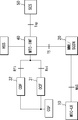
- the architecture is shown in Fig. 1.
- a communication system includes a core network (3GPP network), one or more MTC UEs 10 which connect to the core network through a RAN (Radio Access Network), and an SCS 50 which is placed outside the core network.
- a core network 3GPP network
- MTC UEs 10 which connect to the core network through a RAN (Radio Access Network)
- SCS 50 which is placed outside the core network.
- the RAN is formed by a plurality of base stations (e.g., eNBs (evolved Node Bs)).
- the MTC UE 10 attaches to the core network.
- the MTC UE 10 can host one or multiple MTC Applications.
- the corresponding MTC Applications in the external network are hosted on the SCS 50.
- the SCS 50 connects to the core network to communicate with the MTC UE 10.
- the core network includes, as a part of its network nodes, an MME 20, an OCF (Online Charging Function) 31 for online charging, a CDF (Charging Data Function) 32 for offline charging, and an MTC-IWF 40.
- the core network also includes, as other network nodes, an SGSN (Serving GPRS (General Packet Radio Service) Support Node), an HSS (Home Subscriber Server), a CGF (Charging Gateway Function) and the like.
- the HSS manages subscription information on the MTC UE 10, and the like.
- the MME 20 relays traffic between the RAN and the MTC-IWF 40.
- the SGSN functions as with the MME 20.
- the OCF 31 and the CDF 32 are connected to the CGF. Note that in the following description, the OCF 31 and the CDF 32 are sometimes referred to as "OCF/CDF", and collectively denoted by the symbol 30.
- the MTC-IWF 40 serves as an entering point to the core network for the SCS 50, and relays messages over control plane (reference points "T5" and "Tsp") between the MTC UE 10 and the SCS 50. Meanwhile, different from the typical MTC-IWF, the MTC-IWF 40 records MTC device trigger, and MO (Mobile Originated) and MT (Mobile Terminated) SDT. Moreover, the MTC-IWF 40 generates and transfers the CDRs to the OCF 31 for online charging or to the CDF 32 for offline charging.
- a reference point "Roi” resides between the MTC-IWF 40 and the OCF 31 for online charging.
- a reference point “Rfi” resides between the MTC-IWF 40 and the CDF 32 for offline charging.
- the MTC-IWF 40 is configured with the address of the OCF 31 or the CDF 32, this can be decided by the operator such that the MTC-IWF 40 can distinguish whether it is online or offline charging.
- ⁇ CRD generation> There is proposed to pre-configure rules for charging in the MTC-IWF 40.
- the MTC-IWF 40 Upon receiving a SDT message or an MTC device trigger message, the MTC-IWF 40 verifies whether the message carries SD (Small Data) or device trigger, and the payload size, in order to generate CDR properly.
- SD Small Data
- the MTC-IWF 40 is configured with a counter for charging purpose.
- the CDRs are defined according to the event trigger: MO-SD-CDR, MT-SD-CDR and TRIGGER-CDR.
- the generation of the CDRs is triggered by successful delivery of small data in MO or MT direction and MTC device trigger.
- the MO-SD-CDR is used to collect charging information related to the transmission of SD in MO direction via the MTC-IWF 40 on behalf of the MTC UE 10.
- the event trigger for MO-SD-CDR generation is when the MTC-IWF 40 receives MO SD transmission ACK (Acknowledgement) from the SCS 50.
- the MO-SD-CDR includes details such as CDR type, Counter, UE identifier and subscriber ID if available.
- the MT-SD-CDR is used to collect charging information related to the transmission of SD in MT direction via the MTC-IWF 40 on behalf of the SCS 50.
- the event trigger for MT-SD-CDR generation is when the MTC-IWF 40 receives MT SD transmission ACK from the MTC UE 10.
- the MT-SD-CDR includes details such as CDR type, Counter, UE identifier and subscriber ID if available.
- the TRIGGER-CDR is used to collect charging information related to the delivery of MTC device trigger in downlink direction via the MTC-IWF 40 on behalf of the SCS 50.
- the event trigger for TRIGGER-CDR generation is when the MTC-IWF 40 receives MTC device trigger delivery ACK from the eNB.
- the TRIGGER-CDR includes details such as CDR type, Counter, UE identifier and subscriber ID if available.
- a Record Type field indicates which ones of MO SD messages, MT SD messages and MTC device triggers are counted for generating the CDR.
- a UE Identifier field indicates an identifier of the MTC UE 10.
- An Online/offline field indicates that the CDR is delivered for online or offline.
- An SCS info field indicates information and/or an address of the SCS 50.
- a Serving Node (MTC-IWF) field indicates information and/or an address of the MTC-IWF 40.
- a User Location Information field indicates user location information from which the message is originated.
- a Message Reference field indicates a reference for uniquely identifying the CDR.
- An Event Time Stamp field indicates the time at which the message is received by the MTC-IWF 40.
- a Counter field indicates a value of the counter.
- ⁇ Roaming case> In a case where there is an MTC-IWF in VPLMN (Visited PLMN (Public Land Mobile Network)), the MTC-IWF in VPLMN (V-MTC-IWF) may be configured to record and count MTC device trigger, MO and MT SDT, generate and deliver CDRs. The mechanism is the same as the non-roaming case.
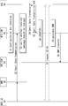
- the MTC-IWF 40 is configured with charging conditions for MO SDT, which includes the SD payload size, counter computation timing, CDR generation and transfer timing.
- Step S1 configuration for charging condition and timing is performed in the MTC-IWF 40 (Step S1).
- the MTC-IWF can generate a COUNTER for the UE subscribed service.
- An initial value of the COUNTER is set with "0".
- the MTC-IWF 40 receives SDT message from the MTC UE 10 (Step S2).
- the MTC-IWF 40 verifies whether or not the received message should be charged (Step S3).
- the MTC-IWF 40 performs the verification based on an indicator which is included in the received message, and which indicates that the received message is the MO SD message, the MT SD message, the MTC device trigger or a different message. In this case, it is possible to simply perform the verification.
- the MTC-IWF 40 may perform the verification further based on the actual size of the received message. As described above, the size of SD message is less than or equal to 1 kB. Therefore, the MTC-IWF 40 determines that the received message should be charged when the actual size is less than or equal to 1 kB. In this case, it is prevent a malicious user from falsifying an indicator in a large size message, which should be charged at a metered rate, for the purpose of receiving services at low cost.
- the MTC-IWF 40 may perform the verification further based on whether or not the MTC device 10 and the SCS 50 are authorized to communicate with each other.
- the MTC-IWF 40 determines that the received message should be charged when both of the MTC device 10 and the SCS 50 have been authorized. In this case, it is possible to prevent charging due to malicious attacks or the like.
- the MTC-IWF 40 delivers the SDT message to the SCS 50 (Step S4).
- the SCS 50 responds a Small Data Transmission ACK message, upon successfully receiving the SDT message (Step S5).
- the MTC-IWF 40 performs counter computation upon receiving the Small Data Transmission ACK message from the SCS 50 (Step 6). Specifically, the MTC-IWF 40 increments the COUNTER by "1".
- Step S7 The above-mentioned Steps S2 to S6 are repeated if any small data transmission needed.
- the MTC-IWF 40 After that, the MTC-IWF 40 generates the MO-SD-CDR, at pre-configured timing (Step S8).
- the MTC-IWF 40 transfers the generated CDR to OCF/CDF 30 at pre-configured timing (Step S9).
- Step S11 configuration for charging condition and timing is performed in the MTC-IWF 40 (Step S11).
- the MTC-IWF can generate a COUNTER for the UE subscribed service.
- An initial value of the COUNTER is set with "0".
- the MTC-IWF 40 receives a MTC device trigger message or a SDT message from the SCS 50 (Step S12).
- the MTC-IWF 40 verifies whether or not the received message should be charged (Step S13). This verification can be performed in a similar manner to that in Fig. 2.
- the MTC-IWF 40 delivers the MTC device trigger message or the SDT message to the MTC UE 10 (Step S14).
- the MTC UE 10 responds a MTC device trigger ACK message or a Small Data Transmission ACK message, upon successfully receiving the MTC device trigger message or the SDT message (Step S15).
- the MTC-IWF 40 performs counter computation upon receiving the MTC device trigger ACK message or the Small Data Transmission ACK message from the MTC UE 10 (Step 16). Specifically, the MTC-IWF 40 increments the COUNTER by "1".
- Step S12 to S16 are repeated if any MTC device trigger or Small Data Transmission needed (Step S17).
- the MTC-IWF 40 After that, the MTC-IWF 40 generates the MT-SD-CDR or the TRIGGER-CDR, at pre-configured timing (Step S18).
- the MTC-IWF 40 transfers the generated CDR to OCF/CDF 30 at pre-configured timing (Step S19).
- the MTC-IWF it is possible to provide the solution for the MTC-IWF to generate and deliver CDRs for charging of SDT and MTC device trigger. Since small data and MTC device triggers packets only have limited size, there is no need to charge the MTC UE based on packet size but numbers of how many SDT or MTC device trigger are being successfully delivered.
- the MTC-IWF can simply have a counter for MO/MT SDT and MTC device trigger charging.
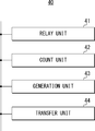
- the MTC-IWF 40 includes a relay unit 41, a count unit 42, and a generation unit 43.
- the relay unit 41 relays MO SD messages, MT SD messages or MTC device trigger messages over the control plane between the MTC UE 10 and the SCS 50.
- the count unit 42 counts the number of messages successfully relayed by using e.g., the abovementioned COUNTER.
- the generation unit 43 generates the MO-SD-CDR, the MT-SD-CDR or the TRIGGER-CDR in accordance with the counted number.
- the MTC-IWF 40 can include a transfer unit 44 which transfers the generated CDR to the OCF/CDF 30.
- these units 41 to 44 are mutually connected with each other through a bus or the like.
- These units 41 to 44 can be configured by, for example, transceivers which conduct communication with the MTC UE 10, the SCS 50, the OCF/CDF 30 and other network nodes within the core network, and a controller such as a CPU (Central Processing Unit) which controls these transceivers.
- a controller such as a CPU (Central Processing Unit) which controls these transceivers.
- MTC-IWF is configured with address of OCF or CDF.
- the counters are defined and configured in MTC-IWF for MO and MT SDT or MTC device trigger delivery charging.
- MTC-IWF records the information for charging.
- MTC-IWF is configured with event triggers for CDRs generation such that it determines which CDR to generate.
- New CDRs are defined: MO-SD-CDR for MO SDT charging, MT-SD-CDR for MT SDT charging and TRIGGER-CDR for MTC device trigger delivery charging.
- MTC-IWF delivers the CDR type, Counter, UE identifier and subscriber ID if available in CDRs to OCF or CDF for online and offline charging separately, over the newly defined interfaces.
Abstract
Description
NPL 2: 3GPP TS 32.240, "Telecommunication management; Charging management; Charging architecture and principles (Release 12)", V12.0.0, 2013-03, Clauses 4.1.1 and 4.1.2, pp. 16
As disclosed in NPL 1, the MTC-IWF can generate CDRs for SDT and MTC device trigger. This exemplary embodiment introduces the solution for the MTC-IWF to generate and deliver CDRs. The architecture is shown in Fig. 1.
A reference point "Roi" resides between the MTC-IWF 40 and the OCF 31 for online charging. A reference point "Rfi" resides between the MTC-IWF 40 and the
There is proposed to pre-configure rules for charging in the MTC-IWF 40. Upon receiving a SDT message or an MTC device trigger message, the MTC-IWF 40 verifies whether the message carries SD (Small Data) or device trigger, and the payload size, in order to generate CDR properly.
There is proposed to create three kinds of event: uplink SD from UE (MO-SD), downlink SD (MT-SD), and MTC device trigger (TRIGGER).

In a case where there is an MTC-IWF in VPLMN (Visited PLMN (Public Land Mobile Network)), the MTC-IWF in VPLMN (V-MTC-IWF) may be configured to record and count MTC device trigger, MO and MT SDT, generate and deliver CDRs. The mechanism is the same as the non-roaming case.
New interfaces (Roi and Rfi) between MTC-IWF and OCF/CDF are defined for CDRs delivery.
MTC-IWF is configured with address of OCF or CDF.
The counters are defined and configured in MTC-IWF for MO and MT SDT or MTC device trigger delivery charging.
MTC-IWF records the information for charging.
MTC-IWF is configured with event triggers for CDRs generation such that it determines which CDR to generate.
New CDRs are defined: MO-SD-CDR for MO SDT charging, MT-SD-CDR for MT SDT charging and TRIGGER-CDR for MTC device trigger delivery charging.
MTC-IWF delivers the CDR type, Counter, UE identifier and subscriber ID if available in CDRs to OCF or CDF for online and offline charging separately, over the newly defined interfaces.
20 MME
30 OCF/CDF
31 OCF
32 CDF
40 MTC-IWF
41 RELAY UNIT
42 COUNT UNIT
43 GENERATION UNIT
44 TRANSFER UNIT
50 SCS
Claims (27)
- A network node comprising:
relay means for relaying messages over a control plane between an MTC (Machine-Type-Communication) device and an SCS (Service Capability Server);
count means for counting the number of messages relayed; and
generation means for generating a CDR (Charging Data Record) in accordance with the counted number.
- The network node according to Claim 1, further comprising:
transfer means for transferring the CDR to an OCF (Online Charging Function) for online charging or a CDF (Charging Data Function) for offline charging.
- The network node according to Claim 1 or 2, wherein the messages comprise at least one of:
a first message delivered from the MTC device to the SCS;
a second message delivered from the SCS to the MTC device; and
a trigger message delivered from the SCS to the MTC device, the trigger message being for causing the MTC device to communicate with the SCS.
- The network node according to Claim 3, wherein the size of the first message is equal to or smaller than a predetermined size, and wherein the size of the second message is equal to or smaller than a predetermined size.
- The network node according to Claim 4, wherein the predetermined size is 1 kB.
- The network node according to any one of Claims 3 to 5, wherein the count means is configured to verify whether or not to count each of the relayed messages based on an indicator included in each of the relayed messages, the indicator indicating that each of the relayed messages is the first message, the second message, the trigger message or a different message.
- The network node according to Claim 6, wherein the count means is configured to perform the verification further based on the actual size of each of the relayed messages.
- The network node according to Claim 7, wherein the count means is configured to perform the verification further based on whether or not the MTC device and the SCS are authorized to communicate with each other.
- The network node according to any one of Claims 3 to 8, wherein the generation means is configured to generate the CDR for each of the first messages, the second messages and the trigger messages.
- The network node according to Claim 9, wherein the generation means is configured to include, in the CDR, a type indicating which ones of the first messages, the second messages and the trigger messages are counted for generating the CDR.
- The network node according to any one of Claims 1 to 10, wherein the generation means is configured to include, in the CDR, an identifier of the MTC device and an identifier of a subscriber.
- The network node according to any one of Claims 1 to 11, wherein the network node comprises an MTC-IWF (MTC Inter-Working Function).
- A communication system comprising:
an MTC (Machine-Type-Communication) device;
an SCS (Service Capability Server); and
a network node that relays messages over a control plane between the MTC device and the SCS,
wherein the network node is configured to:
count the number of messages relayed; and
generate a CDR (Charging Data Record) in accordance with the counted number.
- The communication system according to Claim 13, further comprising:
an OCF (Online Charging Function) for online charging or a CDF (Charging Data Function) for offline charging,
wherein the network node transfers the CDR to the OCF or the CDF.
- The communication system according to Claim 13 or 14, wherein the messages comprise at least one of:
a first message delivered from the MTC device to the SCS;
a second message delivered from the SCS to the MTC device; and
a trigger message delivered from the SCS to the MTC device, the trigger message being for causing the MTC device to communicate with the SCS.
- The communication system according to Claim 15, wherein the size of the first message is equal to or smaller than a predetermined size, and wherein the size of the second message is equal to or smaller than a predetermined size.
- A method of controlling operations in a network node that relays messages over a control plane between an MTC (Machine-Type-Communication) device and an SCS (Service Capability Server), the method comprising:
counting the number of messages relayed; and
generating a CDR (Charging Data Record) in accordance with the counted number.
- The method according to Claim 17, further comprising:
transferring the CDR to an OCF (Online Charging Function) for online charging or a CDF (Charging Data Function) for offline charging.
- The method according to Claim 17 or 18, wherein the messages comprise at least one of:
a first message delivered from the MTC device to the SCS;
a second message delivered from the SCS to the MTC device; and
a trigger message delivered from the SCS to the MTC device, the trigger message being for causing the MTC device to communicate with the SCS.
- The method according to Claim 19, wherein the size of the first message is equal to or smaller than a predetermined size, and wherein the size of the second message is equal to or smaller than a predetermined size.
- The method according to Claim 20, wherein the predetermined size is 1 kB.
- The method according to any one of Claims 19 to 21, further comprising:
verifying, upon the counting, whether or not to count each of the relayed messages based on an indicator included in each of the relayed messages, the indicator indicating that each of the relayed messages is the first message, the second message, the trigger message or a different message.
- The method according to Claim 22, wherein the verification is performed further based on the actual size of each of the relayed messages.
- The method according to Claim 23, wherein the verification is performed further based on whether or not the MTC device and the SCS are authorized to communicate with each other.
- The method according to any one of Claims 19 to 24, wherein the CDR is generated for each of the first messages, the second messages and the trigger messages.
- The method according to Claim 25, further comprising:
including, in the CDR, a type indicating which ones of the first messages, the second messages and the trigger messages are counted for generating the CDR.
- The method according to any one of Claims 17 to 26, further comprising:
including, in the CDR, an identifier of the MTC device and an identifier of a subscriber.
Priority Applications (8)
| Application Number | Priority Date | Filing Date | Title |
|---|---|---|---|
| CN201480050377.6A CN105532022B (en) | 2013-09-12 | 2014-08-04 | Charging for MTC small data transmission and triggering at MTC-IWF |
| EP14776744.6A EP3044946B1 (en) | 2013-09-12 | 2014-08-04 | Charging for mtc small data transmission and trigger at mtc-iwf |
| JP2016512145A JP6489121B2 (en) | 2013-09-12 | 2014-08-04 | Billing for Small Data Transmission and Trigger in MTC-IWF |
| US15/021,492 US10404479B2 (en) | 2013-09-12 | 2014-08-04 | Charging for MTC small data transmission and trigger at MTC-IWF |
| CN202010101238.9A CN111314093B (en) | 2013-09-12 | 2014-08-04 | Network node and charging method thereof, and user equipment and method thereof |
| CN202010100819.0A CN111147267B (en) | 2013-09-12 | 2014-08-04 | Network node and charging method thereof, user equipment and communication method thereof |
| US16/518,805 US20200014548A1 (en) | 2013-09-12 | 2019-07-22 | Charging for mtc small data transmission and trigger at mtc-iwf |
| US16/921,608 US20200336320A1 (en) | 2013-09-12 | 2020-07-06 | Charging for mtc small data transmission and trigger at mtc-iwf |
Applications Claiming Priority (2)
| Application Number | Priority Date | Filing Date | Title |
|---|---|---|---|
| JP2013189776 | 2013-09-12 | ||
| JP2013-189776 | 2013-09-12 |
Related Child Applications (2)
| Application Number | Title | Priority Date | Filing Date |
|---|---|---|---|
| US15/021,492 A-371-Of-International US10404479B2 (en) | 2013-09-12 | 2014-08-04 | Charging for MTC small data transmission and trigger at MTC-IWF |
| US16/518,805 Continuation US20200014548A1 (en) | 2013-09-12 | 2019-07-22 | Charging for mtc small data transmission and trigger at mtc-iwf |
Publications (1)
| Publication Number | Publication Date |
|---|---|
| WO2015037181A1 true WO2015037181A1 (en) | 2015-03-19 |
Family
ID=51626116
Family Applications (1)
| Application Number | Title | Priority Date | Filing Date |
|---|---|---|---|
| PCT/JP2014/004073 WO2015037181A1 (en) | 2013-09-12 | 2014-08-04 | Charging for mtc small data transmission and trigger at mtc-iwf |
Country Status (5)
| Country | Link |
|---|---|
| US (3) | US10404479B2 (en) |
| EP (1) | EP3044946B1 (en) |
| JP (5) | JP6489121B2 (en) |
| CN (3) | CN111147267B (en) |
| WO (1) | WO2015037181A1 (en) |
Cited By (2)
| Publication number | Priority date | Publication date | Assignee | Title |
|---|---|---|---|---|
| CN106851526A (en) * | 2015-12-07 | 2017-06-13 | 阿尔卡特朗讯 | A kind of method and apparatus for processing MTC message |
| WO2018154356A1 (en) * | 2017-02-23 | 2018-08-30 | Nokia Technologies Oy | Method and system for access protocol optimization for narrow band internet-of-things devices within a network environment |
Families Citing this family (7)
| Publication number | Priority date | Publication date | Assignee | Title |
|---|---|---|---|---|
| US10805830B2 (en) * | 2015-08-14 | 2020-10-13 | Telefonaktiebolaget Lm Ericsson (Publ) | Systems and methods for regulating user data traffic in a wireless network |
| CN116054999A (en) | 2016-02-18 | 2023-05-02 | 瑞典爱立信有限公司 | Systems, methods, and apparatus for managing control plane optimized data rates |
| EP3864824B1 (en) * | 2018-10-08 | 2022-08-10 | Telefonaktiebolaget LM Ericsson (publ) | Methods and apparatuses for balancing utilization of computer resources |
| EP3935876A1 (en) * | 2019-03-04 | 2022-01-12 | Telefonaktiebolaget Lm Ericsson (Publ) | Methods and systems for rule based charging for internet of things (iot) support |
| WO2023039732A1 (en) * | 2021-09-14 | 2023-03-23 | Nec Corporation | Method, device and computer storage medium of communication |
| WO2023115350A1 (en) * | 2021-12-21 | 2023-06-29 | Lenovo (Beijing) Limited | Enhanced mechanism on uu interface for mt sdt |
| WO2024020991A1 (en) * | 2022-07-29 | 2024-02-01 | Qualcomm Incorporated | Resource configuration and selection for downlink small data transmissions |
Family Cites Families (13)
| Publication number | Priority date | Publication date | Assignee | Title |
|---|---|---|---|---|
| WO2011063543A1 (en) * | 2009-11-24 | 2011-06-03 | Telefonaktiebolaget L M Ericsson (Publ) | Overcharging prevention by unsent downlink data volume record technical field |
| CN102111739A (en) | 2009-12-24 | 2011-06-29 | 中兴通讯股份有限公司 | MTC charging method and system |
| CN102238520B (en) * | 2010-04-26 | 2014-12-31 | 中兴通讯股份有限公司 | Method and system for transmitting small data packets |
| KR20110121977A (en) | 2010-05-03 | 2011-11-09 | 삼성전자주식회사 | Mobile communication and method for managing signaling message thereof |
| JP2013541278A (en) | 2010-09-09 | 2013-11-07 | ヘッドウォーター パートナーズ I エルエルシー | Wireless network service interface |
| GB201117072D0 (en) | 2011-10-04 | 2011-11-16 | Vodafone Ip Licensing Ltd | Use of non e.164 msisdns |
| EP2759158A2 (en) * | 2011-10-28 | 2014-07-30 | NEC Corporation | Secure method for mtc device triggering |
| CN103327464B (en) * | 2012-03-22 | 2018-08-24 | 中兴通讯股份有限公司 | A kind of charging method and system, information processing entity of MTC communication |
| TWI687077B (en) * | 2012-05-11 | 2020-03-01 | 美商IoT控股公司 | Machine type communication inter-working function (mtc-iwf) node and method of routing a short message |
| WO2013189708A1 (en) * | 2012-06-22 | 2013-12-27 | Nokia Siemens Networks Oy | Machine type communication interworking function |
| US9794772B2 (en) * | 2012-06-22 | 2017-10-17 | Nokia Solutions And Networks Oy | Machine type communication interworking function |
| US8923880B2 (en) * | 2012-09-28 | 2014-12-30 | Intel Corporation | Selective joinder of user equipment with wireless cell |
| US9699323B2 (en) * | 2013-06-28 | 2017-07-04 | Alcatel Lucent | Separate charging for supplemental content in a data flow |
-
2014
- 2014-08-04 CN CN202010100819.0A patent/CN111147267B/en active Active
- 2014-08-04 WO PCT/JP2014/004073 patent/WO2015037181A1/en active Application Filing
- 2014-08-04 CN CN202010101238.9A patent/CN111314093B/en active Active
- 2014-08-04 US US15/021,492 patent/US10404479B2/en active Active
- 2014-08-04 CN CN201480050377.6A patent/CN105532022B/en active Active
- 2014-08-04 JP JP2016512145A patent/JP6489121B2/en active Active
- 2014-08-04 EP EP14776744.6A patent/EP3044946B1/en active Active
-
2019
- 2019-02-28 JP JP2019035061A patent/JP7088554B2/en active Active
- 2019-02-28 JP JP2019035059A patent/JP2019146170A/en active Pending
- 2019-02-28 JP JP2019035060A patent/JP2019146171A/en active Pending
- 2019-07-22 US US16/518,805 patent/US20200014548A1/en not_active Abandoned
-
2020
- 2020-07-06 US US16/921,608 patent/US20200336320A1/en active Pending
-
2021
- 2021-02-19 JP JP2021025710A patent/JP7188475B2/en active Active
Non-Patent Citations (6)
| Title |
|---|
| "3rd Generation Partnership Project; Technical Specification Group Services and System Aspects; Architecture enhancements to facilitate communications with packet data networks and applications (Release 11)", 3GPP STANDARD; 3GPP TS 23.682, 3RD GENERATION PARTNERSHIP PROJECT (3GPP), MOBILE COMPETENCE CENTRE ; 650, ROUTE DES LUCIOLES ; F-06921 SOPHIA-ANTIPOLIS CEDEX ; FRANCE, vol. SA WG2, no. V11.4.0, 22 June 2013 (2013-06-22), pages 1 - 29, XP050692720 * |
| "3rd Generation Partnership Project; Technical Specification Group Services and System Aspects; Machine-Type and other Mobile Data Applications Communications Enhancements (Release 12)", 3GPP STANDARD; 3GPP TR 23.887, 3RD GENERATION PARTNERSHIP PROJECT (3GPP), MOBILE COMPETENCE CENTRE ; 650, ROUTE DES LUCIOLES ; F-06921 SOPHIA-ANTIPOLIS CEDEX ; FRANCE, vol. SA WG2, no. V1.0.0, 17 June 2013 (2013-06-17), pages 1 - 133, XP050692595 * |
| "3rd Generation Partnership Project; Technical Specification Group Services and System Aspects; Service requirements for Machine-Type Communications (MTC); Stage 1 (Release 12)", 3GPP STANDARD; 3GPP TS 22.368, 3RD GENERATION PARTNERSHIP PROJECT (3GPP), MOBILE COMPETENCE CENTRE ; 650, ROUTE DES LUCIOLES ; F-06921 SOPHIA-ANTIPOLIS CEDEX ; FRANCE, vol. SA WG1, no. V12.2.0, 15 March 2013 (2013-03-15), pages 1 - 24, XP050692130 * |
| 3RD GENERATION PARTNERSHIP PROJECT: "3GPP TR 23.887, "Machine-Type and other Mobile Data Applications Communications Enhancements (Release 12)", V 1.0.0,", June 2013 (2013-06-01), pages 23,76, Retrieved from the Internet <URL:Clauses 5.1.1.3.3.1.4 and 5.2.2.3.1.1.2,> |
| 3RD GENERATION PARTNERSHIP PROJECT: "3GPP TS 32.240, "Telecommunication management; Charging management; Charging architecture and principles (Release 12)", V 12.0.0,", March 2013 (2013-03-01), pages 16, Retrieved from the Internet <URL:Clauses 4.1.1 and 4.1.2,> |
| ERICSSON: "Recording Information for Statistical and Offline Charging in M2M;M2M(12)19_072r2_Offline_Charging_in_M2M", ETSI DRAFT; M2M(12)19_072R2_OFFLINE_CHARGING_IN_M2M, EUROPEAN TELECOMMUNICATIONS STANDARDS INSTITUTE (ETSI), 650, ROUTE DES LUCIOLES ; F-06921 SOPHIA-ANTIPOLIS ; FRANCE, vol. M2M, 23 March 2012 (2012-03-23), pages 1 - 9, XP014089691 * |
Cited By (3)
| Publication number | Priority date | Publication date | Assignee | Title |
|---|---|---|---|---|
| CN106851526A (en) * | 2015-12-07 | 2017-06-13 | 阿尔卡特朗讯 | A kind of method and apparatus for processing MTC message |
| WO2018154356A1 (en) * | 2017-02-23 | 2018-08-30 | Nokia Technologies Oy | Method and system for access protocol optimization for narrow band internet-of-things devices within a network environment |
| US10959066B2 (en) | 2017-02-23 | 2021-03-23 | Nokia Technologies Oy | Method and system for access protocol optimization for narrow band Internet-of-Things devices within a network environment |
Also Published As
| Publication number | Publication date |
|---|---|
| CN111314093B (en) | 2022-10-04 |
| JP2019146172A (en) | 2019-08-29 |
| US10404479B2 (en) | 2019-09-03 |
| US20160226668A1 (en) | 2016-08-04 |
| CN105532022A (en) | 2016-04-27 |
| CN111314093A (en) | 2020-06-19 |
| CN111147267B (en) | 2022-06-07 |
| CN105532022B (en) | 2020-07-10 |
| EP3044946A1 (en) | 2016-07-20 |
| CN111147267A (en) | 2020-05-12 |
| JP7188475B2 (en) | 2022-12-13 |
| JP2016535467A (en) | 2016-11-10 |
| US20200336320A1 (en) | 2020-10-22 |
| JP2021078161A (en) | 2021-05-20 |
| US20200014548A1 (en) | 2020-01-09 |
| EP3044946B1 (en) | 2020-06-17 |
| JP2019146170A (en) | 2019-08-29 |
| JP2019146171A (en) | 2019-08-29 |
| JP6489121B2 (en) | 2019-03-27 |
| JP7088554B2 (en) | 2022-06-21 |
Similar Documents
| Publication | Publication Date | Title |
|---|---|---|
| US20200336320A1 (en) | Charging for mtc small data transmission and trigger at mtc-iwf | |
| JP6407170B2 (en) | Method, apparatus and system for aggregating billing information | |
| WO2017088501A1 (en) | Charging method and device | |
| EP2515475B1 (en) | Charging method, network device and mobility management element | |
| KR101894919B1 (en) | Methods and apparatuses for service layer charging correlation with underlying networks | |
| CN102893640A (en) | Methods, systems, and computer readable media for communicating policy information between a policy charging and rules function and a service node | |
| US20180183938A1 (en) | Charging for usage of radio resources that are shared between mtc traffic and non-mtc traffic | |
| EP2314039B1 (en) | Communication system | |
| JPWO2015022764A1 (en) | Wireless communication system and method for charging control | |
| JP6488405B2 (en) | Method and apparatus for performing online charging to GCS | |
| KR102063311B1 (en) | Billing System on Wireless Network | |
| KR20130049963A (en) | System and method for charging loaming data for preventing billing error | |
| CN102036208A (en) | Method and system for acquiring serving general radio packet service support node address |
Legal Events
| Date | Code | Title | Description |
|---|---|---|---|
| WWE | Wipo information: entry into national phase |
Ref document number: 201480050377.6 Country of ref document: CN |
|
| 121 | Ep: the epo has been informed by wipo that ep was designated in this application |
Ref document number: 14776744 Country of ref document: EP Kind code of ref document: A1 |
|
| ENP | Entry into the national phase |
Ref document number: 2016512145 Country of ref document: JP Kind code of ref document: A |
|
| WWE | Wipo information: entry into national phase |
Ref document number: 15021492 Country of ref document: US |
|
| NENP | Non-entry into the national phase |
Ref country code: DE |
|
| REEP | Request for entry into the european phase |
Ref document number: 2014776744 Country of ref document: EP |
|
| WWE | Wipo information: entry into national phase |
Ref document number: 2014776744 Country of ref document: EP |