WO2015029832A1 - Device, method, and program for specifying abnormality-occurrence area of secondary battery system - Google Patents
Device, method, and program for specifying abnormality-occurrence area of secondary battery system Download PDFInfo
- Publication number
- WO2015029832A1 WO2015029832A1 PCT/JP2014/071601 JP2014071601W WO2015029832A1 WO 2015029832 A1 WO2015029832 A1 WO 2015029832A1 JP 2014071601 W JP2014071601 W JP 2014071601W WO 2015029832 A1 WO2015029832 A1 WO 2015029832A1
- Authority
- WO
- WIPO (PCT)
- Prior art keywords
- voltage value
- block voltage
- unit
- module
- block
- Prior art date
Links
Images


Classifications
-
- G—PHYSICS
- G01—MEASURING; TESTING
- G01R—MEASURING ELECTRIC VARIABLES; MEASURING MAGNETIC VARIABLES
- G01R31/00—Arrangements for testing electric properties; Arrangements for locating electric faults; Arrangements for electrical testing characterised by what is being tested not provided for elsewhere
- G01R31/36—Arrangements for testing, measuring or monitoring the electrical condition of accumulators or electric batteries, e.g. capacity or state of charge [SoC]
- G01R31/396—Acquisition or processing of data for testing or for monitoring individual cells or groups of cells within a battery
-
- G—PHYSICS
- G01—MEASURING; TESTING
- G01R—MEASURING ELECTRIC VARIABLES; MEASURING MAGNETIC VARIABLES
- G01R19/00—Arrangements for measuring currents or voltages or for indicating presence or sign thereof
- G01R19/165—Indicating that current or voltage is either above or below a predetermined value or within or outside a predetermined range of values
- G01R19/16533—Indicating that current or voltage is either above or below a predetermined value or within or outside a predetermined range of values characterised by the application
- G01R19/16538—Indicating that current or voltage is either above or below a predetermined value or within or outside a predetermined range of values characterised by the application in AC or DC supplies
- G01R19/16542—Indicating that current or voltage is either above or below a predetermined value or within or outside a predetermined range of values characterised by the application in AC or DC supplies for batteries
-
- G—PHYSICS
- G01—MEASURING; TESTING
- G01R—MEASURING ELECTRIC VARIABLES; MEASURING MAGNETIC VARIABLES
- G01R31/00—Arrangements for testing electric properties; Arrangements for locating electric faults; Arrangements for electrical testing characterised by what is being tested not provided for elsewhere
- G01R31/36—Arrangements for testing, measuring or monitoring the electrical condition of accumulators or electric batteries, e.g. capacity or state of charge [SoC]
- G01R31/3644—Constructional arrangements
- G01R31/3648—Constructional arrangements comprising digital calculation means, e.g. for performing an algorithm
-
- G—PHYSICS
- G01—MEASURING; TESTING
- G01R—MEASURING ELECTRIC VARIABLES; MEASURING MAGNETIC VARIABLES
- G01R31/00—Arrangements for testing electric properties; Arrangements for locating electric faults; Arrangements for electrical testing characterised by what is being tested not provided for elsewhere
- G01R31/36—Arrangements for testing, measuring or monitoring the electrical condition of accumulators or electric batteries, e.g. capacity or state of charge [SoC]
- G01R31/392—Determining battery ageing or deterioration, e.g. state of health
-
- H—ELECTRICITY
- H02—GENERATION; CONVERSION OR DISTRIBUTION OF ELECTRIC POWER
- H02J—CIRCUIT ARRANGEMENTS OR SYSTEMS FOR SUPPLYING OR DISTRIBUTING ELECTRIC POWER; SYSTEMS FOR STORING ELECTRIC ENERGY
- H02J7/00—Circuit arrangements for charging or depolarising batteries or for supplying loads from batteries
- H02J7/0013—Circuit arrangements for charging or depolarising batteries or for supplying loads from batteries acting upon several batteries simultaneously or sequentially
-
- H—ELECTRICITY
- H02—GENERATION; CONVERSION OR DISTRIBUTION OF ELECTRIC POWER
- H02J—CIRCUIT ARRANGEMENTS OR SYSTEMS FOR SUPPLYING OR DISTRIBUTING ELECTRIC POWER; SYSTEMS FOR STORING ELECTRIC ENERGY
- H02J7/00—Circuit arrangements for charging or depolarising batteries or for supplying loads from batteries
- H02J7/0047—Circuit arrangements for charging or depolarising batteries or for supplying loads from batteries with monitoring or indicating devices or circuits
-
- G—PHYSICS
- G01—MEASURING; TESTING
- G01R—MEASURING ELECTRIC VARIABLES; MEASURING MAGNETIC VARIABLES
- G01R1/00—Details of instruments or arrangements of the types included in groups G01R5/00 - G01R13/00 and G01R31/00
-
- G—PHYSICS
- G05—CONTROLLING; REGULATING
- G05B—CONTROL OR REGULATING SYSTEMS IN GENERAL; FUNCTIONAL ELEMENTS OF SUCH SYSTEMS; MONITORING OR TESTING ARRANGEMENTS FOR SUCH SYSTEMS OR ELEMENTS
- G05B2219/00—Program-control systems
-
- G—PHYSICS
- G07—CHECKING-DEVICES
- G07C—TIME OR ATTENDANCE REGISTERS; REGISTERING OR INDICATING THE WORKING OF MACHINES; GENERATING RANDOM NUMBERS; VOTING OR LOTTERY APPARATUS; ARRANGEMENTS, SYSTEMS OR APPARATUS FOR CHECKING NOT PROVIDED FOR ELSEWHERE
- G07C2205/00—Indexing scheme relating to group G07C5/00
Definitions
- the present invention relates to an apparatus, a method, and a program for specifying an abnormality occurrence site in a secondary battery system having two or more modules each including one or more blocks each having two or more secondary battery cells connected to each other. .
- the frequency adjustment of the power system and the adjustment of power demand and supply power of the power system are performed by a plurality of generators and storage batteries in the system.
- adjustment of the difference between the generated power from the natural energy power generation device and the planned output power and the relaxation of fluctuations in the generated power from the natural energy power generation device are often performed by a plurality of generators, storage batteries, and the like.
- the storage battery can change the output power at a higher speed than a general generator, adjust the frequency of the power system, adjust the difference between the generated power from the natural energy generator and the planned output power, It is effective for adjusting power demand and power supply.
- NaS battery sodium-sulfur battery
- This NaS battery is a high-temperature secondary battery having a structure in which metallic sodium and sulfur, which are active materials, are separated and housed by a solid electrolyte tube. When heated to about 300 ° C., the electrochemical reaction of both molten active materials As a result, predetermined energy is generated.
- NaS batteries are used in the form of modules in which a plurality of single cells are assembled and connected to each other.
- the module has a structure in which a circuit (string) in which a plurality of single cells are connected in series is connected in parallel to form a block, and at least two or more such blocks are connected in series and then accommodated in a heat insulating container.
- a method for reporting the occurrence of such a module abnormality a method is disclosed in which a battery abnormality is detected and reported by comparing the discharge depth of each block (for example, Japanese Patent Laid-Open No. 3-158781). reference).
- the presence or absence of abnormality is determined for each block constituting the module. Therefore, it is preferable in that the apparatus is not complicated and the manufacturing cost can be reduced as compared with the method of detecting an abnormality for each individual NaS cell constituting the block.
- the cause of the failure of the unit cell and the failure of the module is the internal short circuit or the external short circuit of the unit cell.
- the external short circuit of the unit cell includes the formation of an external short circuit loop due to leakage of the active material in the unit cell.
- An internal short circuit of the unit cell may be a short circuit due to a beta tube breakage or the like.
- An object of the present invention is to provide an apparatus, a method, and a program for identifying an abnormality occurrence site of a secondary battery system that can be implemented.
- the apparatus provides a site where an abnormality has occurred in a secondary battery system having a plurality of modules in which one or more blocks each having two or more secondary battery cells are connected.
- a device for specifying a voltage measuring unit that detects the voltage of the secondary battery in units of blocks and outputs it as a block voltage value every unit time, and a block voltage value from the voltage measuring unit every unit time Based on the average block voltage calculation unit for calculating the average block voltage value for each module, the block voltage value, the reference block voltage value obtained from the correlation between the corresponding average block voltage value of the module, When the difference from the block voltage value is equal to or greater than a preset voltage threshold value, information on the module that contains the block that is the output source of the block voltage value (module information) ), An information receiving unit that receives a report on the occurrence of an abnormality in the secondary battery, and a module that corresponds to the module information when receiving the report at the report receiving unit. And a module identifying unit that identifies the
- the block voltage value of the block containing the shorted unit cell sharply decreases, but after that, it may return to the voltage before the short circuit after a certain period of time. . Further, as the system scale increases, the number of monitored blocks increases accordingly, and it becomes even more difficult to detect a voltage drop due to a short circuit from changes in block voltage values of all blocks.
- the block Since the information of the module containing the block that is the output source of the voltage value is acquired, it is possible to accurately detect whether or not the block voltage has been reduced, and it is possible to detect the occurrence of an abnormality due to a short circuit.
- the present invention it is possible to identify the module that is the source of the abnormality and report it to the local user, local administrator, etc., and take countermeasures mainly on the identified abnormality source. This can be done at an early stage, and the spread of damage can be suppressed.
- the information acquisition unit includes a voltage comparison unit that compares a difference between the block voltage value and the reference block voltage value with a preset voltage threshold value
- the voltage comparison unit includes a linear regression processing unit that obtains information of one regression line by performing linear regression processing on a relationship between a plurality of block voltage values and a plurality of average block voltage values accumulated in a certain period, and unit time
- a reference voltage acquisition unit that obtains the reference block voltage value corresponding to the block voltage value based on the information of the regression line.
- the linear regression processing unit accumulates the plurality of block voltage values and the plurality of average block voltage values in the certain period, and in parallel, accumulates in the previous certain period.
- Information on one regression line may be obtained by performing linear regression processing on the relationship between the plurality of block voltage values and the plurality of average block voltage values.
- the regression line is updated every fixed period, and the reference voltage acquisition unit obtains the reference block voltage value in the fixed period this time during the previous fixed period. You may perform based on the information of the said regression line.
- the linear regression processing unit accumulates the plurality of block voltage values and the plurality of average block voltage values during the certain period, and corresponds to the last unit time of the certain period. In a period, information on one regression line may be obtained by performing linear regression processing on the relationship between the plurality of block voltage values accumulated in the certain period and the plurality of average block voltage values.
- the regression line is updated every fixed period, and the reference voltage acquisition unit acquires the reference block voltage value in the current fixed period at the end of the previous fixed period. You may perform based on the information of the said regression line obtained in the period corresponded to unit time.
- the block voltage value is input to the linear regression processing unit and the reference voltage acquisition unit via a delay circuit that is delayed for the predetermined period, and the average block The voltage value may be input to the linear regression processing unit via a delay circuit that is delayed for the predetermined period. This makes it possible to arbitrarily set the fixed period according to the system scale or the like, and is versatile.
- the delay time of the delay circuit may be selected according to a behavior in which the block voltage temporarily drops due to a short circuit of at least one unit cell. Thereby, the detection accuracy of a block in which the block voltage temporarily drops due to a short circuit of at least one unit cell can be increased.
- a voltage value at which a block voltage temporarily drops due to a short circuit of at least one unit cell may be selected as the voltage threshold.
- the first aspect of the invention may include an error output unit that receives the module information from the information acquisition unit and outputs the module information together with an error message.
- an error output unit that receives the module information from the information acquisition unit and outputs the module information together with an error message.
- the method according to the second aspect of the present invention provides an abnormality occurrence site of a secondary battery system having a plurality of modules in which one or more blocks each including two or more secondary battery cells are connected.
- a voltage measuring step for detecting a voltage of the secondary battery in a block unit and outputting it as a block voltage value for each unit time, and a block voltage value from the voltage measuring step for each unit time.
- An average block voltage calculation step for calculating an average block voltage value for each module, a reference block voltage value obtained from the correlation between the block voltage value and the average block voltage value of the corresponding module, and A module containing a block that is an output source of the block voltage value when the difference from the block voltage value is equal to or greater than a preset voltage threshold value
- a module specifying step for specifying the module as a module in which an abnormality has occurred.
- a program includes a plurality of modules each including one or more blocks each having two or more secondary battery cells connected thereto, and the secondary battery for each unit time.
- a voltage measurement unit that detects the voltage of each block and outputs it as a block voltage value, and an average block that calculates an average block voltage value for each module based on the block voltage value from the voltage measurement unit per unit time
- a secondary battery system having a voltage calculation unit, the difference between the block voltage value and the reference block voltage value obtained from the correlation between the average block voltage value of the corresponding module, and the block voltage value,
- An information acquisition method for acquiring information (module information) of a module containing a block that is an output source of the block voltage value when the voltage threshold value is equal to or higher than a preset voltage threshold value.
- a module for identifying a module corresponding to the module information as a module in which an abnormality has occurred when receiving the report at the report receiving unit; It is a program that functions as a means.
- the module (or block) that is the source of the abnormality is early introduced. It is possible to identify the initial action when an abnormality occurs.
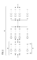
- FIG. 7A is a graph showing an example of changes in the block voltage value and the average block voltage value over a certain period
- FIG. 7B shows a correlation diagram between the average block voltage value and the block voltage value and a regression line that matches the correlation diagram.
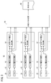
- FIG. 8A is a timing chart showing a first processing sequence in the linear regression processing section
- FIG. 8B is a timing chart showing a second processing sequence.
- FIG. 10A is a flowchart showing an example of the processing operation of the information requesting unit
- FIG. 10B is a flowchart showing an example of the processing operation of the voltage value storage unit of the linear regression processing unit
- FIG. 10C is a regression line of the linear regression processing unit.
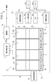
- the secondary battery system 10 to which the apparatus, method, and program according to the present embodiment are applied includes a secondary battery storage unit 12, an abnormality detection unit 14, and a reporting unit 16, as shown in FIG. Have.
- the secondary battery storage unit 12 has a configuration in which a plurality of box-shaped packages 18 are arranged in the horizontal direction. In the example of FIG. 1, four packages 18 (first package 18A to fourth package 18D) are arranged in the horizontal direction.
- the secondary battery storage unit 12 also includes a battery control device 20 that controls the operation of the secondary battery.
- Each package 18 accommodates a module row 24 in which two or more modules 22 are stacked in the vertical direction, and these two or more modules 22 are connected in series.
- a module row 24 in which two or more modules 22 are stacked in the vertical direction, and these two or more modules 22 are connected in series.
- FIG. 1 an example is shown in which one module row 24 is configured by stacking five modules 22.
- the module 22 includes two or more blocks 26 connected in series, and each block 26 includes two or more circuits (strings 30) in which two or more secondary battery cells 28 are connected in series. ) Are connected in parallel. For example, eight cells 28 are connected in series to form one string 30, twelve strings 30 are connected in parallel to form one block 26, and four blocks 26 are connected in series to 1
- the secondary battery include a NaS battery, a lithium ion battery, and a sodium ion battery.
- the abnormality detection unit 14 detects an abnormality such as a fire based on a signal from a sensor 32 (heat sensor, smoke sensor, etc.) installed in each package 18.
- the reporting unit 16 makes a report (abnormal report) indicating the occurrence of an abnormality to the monitoring center or the like based on the input of the abnormality detection signal Sa (signal indicating that an abnormality has been detected) from the abnormality detection unit 14.
- the report may be made via a public communication network such as the Internet or a mobile phone network.
- reporting may be made to local users, local managers, and the like.
- the reporting unit 16 outputs an operation stop signal Sb to the battery control device 20 in addition to the above-described notification based on the input of the abnormality detection signal Sa from the abnormality detection unit 14.
- the battery control device 20 stops the operation of the secondary battery according to a preset sequence for operation stop based on the input of the operation stop signal Sb.
- an apparatus for identifying an abnormality occurrence site includes an information transmission unit 52, an information acquisition unit 54, and a notification reception unit. 56 and a module specifying unit 58.
- the information transmission unit 52 has a plurality of voltage value output units 60 installed in the module row 24 unit. As shown in FIG. 3, each voltage value output unit 60 includes a plurality of block voltage measurement units 62 installed in units of blocks, a plurality of average block voltage calculation units 64 installed in units of modules 22, and one transmission. And a file creation unit 66.
- the block voltage measuring unit 62 measures the voltage across the corresponding block 26 in accordance with a preset monitoring cycle. For example, the voltage across the corresponding block 26 is measured at a time interval arbitrarily selected from 0.5 seconds to 2 seconds (for example, 1 second interval: monitoring cycle).
- the average block voltage calculation unit 64 calculates the average block voltage value Va of the corresponding module 22 based on the block voltage value V from the block voltage measurement unit 62 every monitoring period.
- Each transmission file creation unit 66 creates a transmission file 68 including information on the corresponding module row 24 for each monitoring period.
- Examples of the information related to the module row 24 include an identification number (module row information) of the module row 24, information about a plurality of modules 22 included in the module row 24, and the like.
- the information related to the module 22 includes an identification number (module information) of the module 22, an average block voltage value Va of the module 22, identification numbers (block information) of a plurality of blocks 26 included in the module 22, and a plurality of information The current block voltage value V and the like corresponding to each block 26 are listed.
- the format of the transmission file 68 relating to the first module row 24 is as follows. As shown in FIG. 4, the identification number ( MR1) and information relating to a plurality of modules 22 included in the first module row 24.
- the format of the information on the first module 22 as an example, the identification number (M1) of the first module 22, the average block voltage value Va of the module 22, the module 22 And information regarding a plurality of blocks 26 included in.
- the information regarding the plurality of blocks 26 includes the following information and the like.
- (1a) Identification number (B1) of the first block 26 (1b) Current block voltage value V of the first block 26 (1c) Identification number (B2) of the second block 26 (1d) Current block voltage value V of the second block 26 (1e) Identification number (B3) of the third block 26 (1f) Current block voltage value V of the third block 26 (1g) Identification number of the fourth block 26 (B4) (1h) Current block voltage value V of the fourth block 26
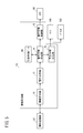
- the information acquisition unit 54 determines that the difference between the block voltage value V and the reference block voltage value Vb obtained from the correlation between the block voltage value V and the average block voltage value Va is a preset voltage threshold value. In the case of Vth or higher, information on the module 22 that houses the block 26 that is the output source of the block voltage value V is acquired.
- the information acquisition unit 54 includes an information request unit 70, a voltage comparison unit 72, a warning information creation unit 74, a warning information storage unit 76, and a warning information output unit 78.
- the information request unit 70 requests each voltage value output unit 60 of the information transmission unit 52 to transmit information every monitoring cycle.
- Each voltage value output unit 60 transmits a transmission file 68 including information regarding the corresponding module row 24 to the information request unit 70 based on the information transmission request from the information request unit 70.
- the voltage comparison unit 72 includes a linear regression processing unit 80, a reference voltage acquisition unit 82, a subtractor 84, and a voltage comparison circuit 86 as illustrated in FIG.
- the linear regression processing unit 80 performs linear regression processing on the relationship between the plurality of block voltage values V and the plurality of average block voltage values Va accumulated in a certain period to obtain information on one regression line.
- the reference voltage acquisition unit 82 obtains a reference block voltage value Vb corresponding to the block voltage value V based on the regression line information for each unit time.
- the subtracter 84 takes the difference (difference voltage value ⁇ V) between the block voltage value V and the reference block voltage value Vb.
- the voltage comparison circuit 86 compares the difference voltage value ⁇ V from the subtractor 84 with a preset voltage threshold value Vth.
- the block voltage value V is input to the linear regression processing unit 80, the reference voltage acquisition unit 82, and the subtractor 84 through the first delay circuit 88a, and the average block voltage value Va is linearly input through the second delay circuit 88b. Input to the regression processing unit 80.
- the linear regression processing unit 80 includes a voltage value storage unit 90 and a regression line creation unit 92.
- the voltage value accumulation unit 90 accumulates a plurality of block voltage values V and a plurality of average block voltage values Va input every unit time over a certain period in the first memory 94a.
- the regression line creation unit 92 creates a correlation diagram (dispersion diagram) between the plurality of block voltage values V and the plurality of average block voltage values Va stored in the first memory 94a, and a regression line (consistent diagram) that matches this correlation diagram ( Map information) is obtained by performing a least-squares regression process and stored in the second memory 94b.
- the voltage value accumulating unit 90 takes in the block voltage value V and the average block voltage value Va every second, and is constant. In the period, 20 block voltage values V and 20 average block voltage values Va are stored in the first memory 94a. Then, as shown in FIG. 7B, a correlation diagram between the average block voltage value Va and the block voltage value V accumulated in the first memory 94a is created, and the regression line La (map information) matching this correlation diagram is minimized. It calculates
- the average block voltage value Va on the regression line La corresponding to the block voltage value V becomes the reference block voltage value Vb corresponding to the block voltage value V. Therefore, the reference voltage acquisition unit 82 acquires the reference block voltage value Vb corresponding to the block voltage value V based on the map information of the regression line La for each monitoring period.
- the voltage comparison circuit 86 sends an event log signal Sel from the voltage comparison circuit 86 to the warning information creation unit 74. Is output.
- the first processing sequence is a linear regression due to delays in the first delay circuit 88a and the second delay circuit 88b during a certain period (cycle 1) from the time t1 when the secondary battery system 10 is started.
- the block voltage value V and the average block voltage value Va are not input to the processing unit 80.
- the input of the block voltage value V and the average block voltage value Va to the linear regression processing unit 80 is started from the start time t2 of the next fixed period (cycle 2).
- the block voltage value V and the average block voltage value Va are input for each monitoring period over this fixed period and stored in the first memory 94a.
- the block voltage value V and the average block voltage value Va are input for each monitoring cycle, and the following processing is performed in parallel with being stored in the first memory 94a. That is, the regression line La (map information) is created on the basis of the block voltage value V and the average block voltage value Va for a certain period (cycle 2) previously accumulated in the regression line creation unit 92 and stored in the second memory 94b. Is done.
- the regression line La (map information) is not created in a period (cycle 1 to cycle 3) extending from 3 to (a certain period) from the time t1 when the secondary battery system 10 is started. That is, the operation stop period Ts of the reference voltage acquisition unit 82 and the voltage comparison circuit 86 is set.
- the block voltage value V and the average block voltage value Va are input for each monitoring period, and the following processing is performed in parallel with the accumulation in the first memory 94a. That is, the regression line creation unit 92 creates a regression line La (map information) based on the block voltage value V and the average block voltage value Va accumulated in the first memory 94a in the previous fixed period (cycle 3). 2 is stored in the memory 94b.
- the reference block voltage value Vb corresponding to the block voltage value V is acquired for each monitoring cycle based on the regression line La (map information) created in the previous fixed period (cycle 3). The Then, the difference (difference voltage value ⁇ V) between the block voltage value V and the reference block voltage value Vb is compared with a preset voltage threshold value Vth.
- processing similar to cycle 4 is performed.
- the second processing sequence is a linear regression due to delays in the first delay circuit 88a and the second delay circuit 88b during a certain period (cycle 1) from the time t1 when the secondary battery system 10 is started.
- the block voltage value V and the average block voltage value Va are not input to the processing unit 80.
- the input of the block voltage value V and the average block voltage value Va to the linear regression processing unit 80 is started from the start time t2 of the next fixed period (cycle 2). Over this fixed period (cycle 2), the block voltage value V and the average block voltage value Va are input for each monitoring period and stored in the first memory 94a. In a period corresponding to the last monitoring cycle of cycle 2, the regression line creation unit 92 creates a regression line La (map information) based on the block voltage value V and the average block voltage value Va accumulated in cycle 2. And stored in the second memory 94b.
- the block voltage value V and the average block voltage value Va are input for each monitoring period and stored in the first memory 94a.
- the regression line creation unit 92 creates a regression line La (map information) based on the block voltage value V and the average block voltage value Va accumulated in the cycle 3 and generates the second.
- the reference block voltage value Vb corresponding to the block voltage value V is acquired for each monitoring period based on the regression line La (map information) created in the previous fixed period (cycle 2).
- the difference (difference voltage value ⁇ V) between the block voltage value V and the reference block voltage value Vb is compared with a preset voltage threshold value Vth.
- the delay time in the first delay circuit 88a and the second delay circuit 88b described above is a time corresponding to a certain period. This time can be selected according to the behavior in which the corresponding string 30 is insulated and the block voltage value V temporarily decreases due to, for example, a short circuit of one single cell 28. For example, a time arbitrarily selected from 10 to 60 seconds (for example, 20 seconds) can be selected. Further, as the voltage threshold value Vth, a voltage value that temporarily drops due to a short circuit of one unit cell 28, for example, 200 mV or the like can be selected.
- the warning information creation unit 74 Based on the input of the event log signal Sel output from the voltage comparison circuit 86, the warning information creation unit 74 creates warning information data 96 (see FIG. 9) in which the following information is registered, and the warning information storage unit 76 To the warning information output unit 78.
- Identification number module string information
- Module 22 identification number module 22 identification number
- Block 26 identification number block information
- one warning information data 96 includes, in order from the top, the current date (year, month, day), current time (hour, minute), module string information, module information, and block information. And the current block voltage value V is stored.
- the warning information storage unit 76 stores the warning information data 96 created by the warning information creation unit 74 in a memory 98 of a stack method (last-in first-out method). As a result, when the warning information data 96 is extracted from the memory 98, the latest warning information data 96 is extracted.
- the warning information output unit 78 converts the warning information data 96 sequentially sent from the warning information creation unit 74 into display data and printing data, respectively, and sends an error message (for example, “short circuit abnormality”) to the monitor 100 and the printer 102. Message).
- an error message for example, “short circuit abnormality”
- warning information (year / month / day, time, module column information, module information, block information, current block voltage value V) is displayed on the monitor 100 together with the error message, and further displayed on the printer 102 together with the error message.
- the report receiving unit 56 receives a report (abnormal report) indicating the occurrence of an abnormality from the report unit 16, as shown in FIG. Specifically, the module specifying unit 58 is activated when the abnormality information is received.
- the module identifying unit 58 identifies the module 22 corresponding to the module string information and the module information registered in the latest warning information data 96 among the plurality of modules 22 as the module 22 in which an abnormality has occurred.
- the module specifying unit 58 starts the operation based on the activation by the report receiving unit 56, and corresponds to the module string information and the module information registered in the latest warning information data 96 stored in the memory 98.
- the module 22 is specified as the module 22 in which an abnormality has occurred. Communication of the identified module 22 to the operator or the like is performed by outputting module information and an error message (for example, “Accident has occurred in the first module”) to the monitor 100 or the printer 102.
- an image with an accident symbol at the position of the specified module 22 is displayed on the monitor 100 or printed on a print sheet. The position 22 can be recognized at a glance, which is preferable.
- each functional unit constituting the information acquisition unit 54 operates in a multitasking manner.
- each voltage value output unit 60 of the information transmission unit 52 is requested to transmit information.
- Each voltage value output unit 60 transmits a transmission file 68 including information on the corresponding module sequence 24 to the information acquisition unit 54 based on the information transmission request from the information request unit 70.
- step S2 the information request unit 70 receives the transmission file 68 from each voltage value output unit 60.
- step S3 it is determined whether or not there is a termination request (such as a termination request due to power interruption or maintenance) to the information requesting unit 70. If there is no termination request, the process returns to step S1, and the processing from step S1 is repeated. On the other hand, when the termination request is received, the processing in the information request unit 70 is terminated.
- a termination request such as a termination request due to power interruption or maintenance
- step S101 the block voltage value V of all the blocks 26 included in the acquired transmission file 68 and the average block voltage value Va for each module are captured and stored in the first memory 94a.
- step S102 it is determined whether or not there is an end request for the voltage value storage unit 90 of the linear regression processing unit 80. If there is no end request, the process returns to step S101, and the processes after step S101 are repeated. On the other hand, when the termination request is made, the processing in the voltage value accumulation unit 90 is terminated.
- step S201 a regression line La (map information) is created based on the block voltage value V and the average block voltage value Va accumulated in the first memory 94a and stored in the second memory 94b.
- step S202 it is determined whether or not there is a termination request for the regression line creation unit 92 of the linear regression processing unit 80. If there is no termination request, the process returns to step S201, and the processing after step S201 is repeated. On the other hand, when the termination request is made, the process in the regression line creation unit 92 is terminated.
- step S301 it is determined whether or not it is the operation stop period Ts. If it is the operation stop period Ts, the process waits until the operation stop period Ts ends, and proceeds to the next step S302 when the operation stop period Ts ends.
- the reference voltage acquisition unit 82 acquires a reference block voltage value Vb corresponding to the block voltage value V based on the latest regression line La (map information) created by the regression line creation unit 92.
- step S303 the subtractor 84 takes the difference (difference voltage value ⁇ V) between the block voltage value V and the reference block voltage value Vb.
- step S304 the voltage comparison circuit 86 calculates the difference voltage value ⁇ V and the voltage threshold value. Compare with Vth. If it is determined in step S305 that the differential voltage value ⁇ V is equal to or greater than the voltage threshold value Vth, the process proceeds to step S306, and the event log signal Sel is output from the voltage comparison circuit 86 to the warning information creation unit 74.
- the warning information creation unit 74 creates warning information data 96. Specifically, warning information data 96 in which the following information is registered is created. (3a) Current date and time (3b) Identification number (module string information) of the module string 24 that contains the block 26 corresponding to the voltage comparison circuit 86 that is the output source of the event log signal Sel (3c) Module 22 identification number (module information) (3d) Block 26 identification number (block information)
- step S308 the warning information output unit 78 converts the generated warning information data 96 into display data and print data, respectively, and sends an error message (for example, “short circuit abnormality occurrence” or the like) to the monitor 100 and the printer 102. Message).
- an error message for example, “short circuit abnormality occurrence” or the like
- step S309 the warning information storage unit 76 stores the warning information data 96 created by the warning information creation unit 74 in the memory 98 of the stack method (last-in first-out method).
- step S310 the notification receiving unit 56 determines whether there is a notification (abnormality notification) indicating the occurrence of an abnormality from the notification unit 16. If no abnormality notification has been received, the process returns to step S302, and the processes after step S302 are repeated.
- a notification abnormality notification
- the process proceeds to the next step S311 and processing in the module identification unit 58 is performed. That is, the module string information registered in the latest warning information data 96 stored in the memory 98 and the module 22 corresponding to the module information are identified as the module 22 in which an abnormality has occurred. Then, the module information and error message regarding the identified module 22 are output to the monitor 100 and the printer 102.
- step S312 it is determined whether or not there is an end request for the information acquisition unit 54. If there is no end request, the process returns to step S302, and the processes in and after step S302 are repeated. On the other hand, when the termination request is made, the processing in the reference voltage acquisition unit 82, the subtractor 84, the voltage comparison circuit 86, the warning information creation unit 74, etc. is terminated.
- the abnormal site specifying device 50 and the abnormal specifying method according to the present embodiment have the following effects.
- the block voltage value V of the block 26 including the short-circuited unit cell 28 sharply decreases, but then 1.5 to 2 minutes have passed. At this stage, the voltage before the short circuit may be restored. Further, as the system scale increases, the number of blocks to be monitored increases accordingly, and it becomes even more difficult to detect a voltage drop due to a short circuit from a change in the block voltage value V of all the blocks 26.
- the block voltage value V is temporarily detected as a drop due to a short circuit of at least one unit cell 28 and erroneously detected.
- the present embodiment information on the following modules 22 among the plurality of modules 22 is acquired. That is, when the difference ⁇ V between the reference block voltage value Vb obtained from the correlation between the block voltage value V and the average block voltage value Va and the block voltage value V is equal to or greater than a preset voltage threshold value Vth.
- the information of the module 22 that houses the block 26 that is the output source of the block voltage value V is acquired.
- the warning information data 96 is created based on the acquired information of the module 22, and at the time of receiving the abnormality report in the report receiving unit 56, at least the module 22 corresponding to the latest warning information data 96 has an abnormality. Identifies as a module. As a result, it becomes possible to identify the module 22 that is the source of the abnormality and report it to the local user, local manager, etc., and take action quickly with the identified abnormality source as the center. It is possible to suppress the spread of damage.
- the detection accuracy of the block 26 in which the block voltage value V temporarily drops due to a short circuit of at least one unit cell 28 can be further increased.
- a short circuit of at least one unit cell 28 prevents erroneous detection as a temporary drop in the block voltage value V.
- the linear regression processing unit 80 performs linear regression processing on the relationship between a plurality of block voltage values V and a plurality of average block voltage values Va accumulated in a certain period, thereby obtaining one regression line La (map). Information). Further, the reference voltage acquisition unit 82 acquires the reference block voltage value Vb corresponding to the block voltage value V based on the information of the regression line La for each unit time. Thereby, the reference block voltage value Vb based on the correlation between the block voltage value V and the average block voltage value Va can be easily obtained, and the calculation speed can be increased.
- the apparatus, method, and program for specifying an abnormality occurrence site of the secondary battery system according to the present invention are not limited to the above-described embodiments, and can adopt various configurations without departing from the gist of the present invention. Of course.
Abstract
Description
(1a) 第1番目のブロック26の識別番号(B1)
(1b) 第1番目のブロック26の現在のブロック電圧値V
(1c) 第2番目のブロック26の識別番号(B2)
(1d) 第2番目のブロック26の現在のブロック電圧値V
(1e) 第3番目のブロック26の識別番号(B3)
(1f) 第3番目のブロック26の現在のブロック電圧値V
(1g) 第4番目のブロック26の識別番号(B4)
(1h) 第4番目のブロック26の現在のブロック電圧値V The information regarding the plurality of
(1a) Identification number (B1) of the
(1b) Current block voltage value V of the
(1c) Identification number (B2) of the
(1d) Current block voltage value V of the
(1e) Identification number (B3) of the
(1f) Current block voltage value V of the
(1g) Identification number of the fourth block 26 (B4)
(1h) Current block voltage value V of the
(2a) イベントログ信号Selの出力元である電圧比較回路86に対応するブロック26を収容したモジュール列24の識別番号(モジュール列情報)
(2b) モジュール22の識別番号(モジュール情報)
(2c) ブロック26の識別番号(ブロック情報) Based on the input of the event log signal Sel output from the
(2a) Identification number (module string information) of the
(2b)
(2c)
(3a) 現在の日付、時刻
(3b) イベントログ信号Selの出力元である電圧比較回路86に対応するブロック26を収容したモジュール列24の識別番号(モジュール列情報)
(3c) モジュール22の識別番号(モジュール情報)
(3d) ブロック26の識別番号(ブロック情報) In step S307, the warning
(3a) Current date and time (3b) Identification number (module string information) of the
(3c)
(3d)
Claims (13)
- 2以上の二次電池の単電池(28)が接続されてなる1以上のブロック(26)が収容されてなる複数のモジュール(22)を有する二次電池システム(10)の異常発生部位を特定する装置であって、
単位時間毎に、前記二次電池の電圧をブロック単位に検出してブロック電圧値(V)として出力する電圧計測部(62)と、
単位時間毎に、前記電圧計測部(62)からのブロック電圧値(V)に基づいて、モジュール毎の平均ブロック電圧値(Va)を算出する平均ブロック電圧算出部(64)と、
前記ブロック電圧値(V)と、対応する前記モジュール(22)の平均ブロック電圧値(Va)との相関関係から得られた基準ブロック電圧値(Vb)と、前記ブロック電圧値(V)との差が、予め設定された電圧しきい値(Vth)以上の場合に、該ブロック電圧値(V)の出力元であるブロック(26)を収容したモジュール(22)のモジュール情報を取得する情報取得部(54)と、
前記二次電池の異常発生の通報を受信する通報受信部(56)と、
前記通報受信部(56)での前記通報の受信の際に、前記モジュール情報に対応するモジュール(22)を、異常発生したモジュールとして特定するモジュール特定部(58)とを有することを特徴とする装置。 Identifies a site where an abnormality has occurred in the secondary battery system (10) having a plurality of modules (22) in which one or more blocks (26) formed by connecting two or more secondary battery cells (28) are accommodated. A device that performs
A voltage measuring unit (62) for detecting the voltage of the secondary battery in units of blocks and outputting the voltage as a block voltage value (V) for each unit time;
An average block voltage calculation unit (64) for calculating an average block voltage value (Va) for each module based on the block voltage value (V) from the voltage measurement unit (62) for each unit time;
The reference block voltage value (Vb) obtained from the correlation between the block voltage value (V) and the average block voltage value (Va) of the corresponding module (22), and the block voltage value (V) Information acquisition for acquiring module information of the module (22) containing the block (26) that is the output source of the block voltage value (V) when the difference is equal to or greater than a preset voltage threshold value (Vth). Part (54);
A notification receiver (56) for receiving a notification of the occurrence of an abnormality in the secondary battery;
A module specifying unit (58) that specifies a module (22) corresponding to the module information as a module in which an abnormality has occurred when the notification is received by the report receiving unit (56). apparatus. - 請求項1記載の装置において、
前記情報取得部(54)は、
前記ブロック電圧値(V)と前記基準ブロック電圧値(Vb)との差と、予め設定された電圧しきい値(Vth)とを比較する電圧比較部(72)を有し、
前記電圧比較部(72)は、
一定期間に蓄積された複数のブロック電圧値(V)と複数の平均ブロック電圧値(Va)の関係を直線回帰処理して1つの回帰直線の情報を得る直線回帰処理部(80)と、
単位時間毎に、前記回帰直線の情報に基づいて前記ブロック電圧値(V)に対応する前記基準ブロック電圧値(Vb)を得る基準電圧取得部(82)とを有することを特徴とする装置。 The apparatus of claim 1.
The information acquisition unit (54)
A voltage comparison unit (72) for comparing a difference between the block voltage value (V) and the reference block voltage value (Vb) with a preset voltage threshold value (Vth);
The voltage comparison unit (72)
A linear regression processing unit (80) that obtains information of one regression line by performing linear regression processing on the relationship between a plurality of block voltage values (V) and a plurality of average block voltage values (Va) accumulated in a certain period;
A reference voltage acquisition unit (82) that obtains the reference block voltage value (Vb) corresponding to the block voltage value (V) based on the information of the regression line for each unit time. - 請求項2記載の装置において、
前記直線回帰処理部(80)は、
前記一定期間に、前記複数のブロック電圧値(V)と前記複数の平均ブロック電圧値(Va)を蓄積し、それと並行して、前回の前記一定期間に蓄積された複数のブロック電圧値(V)と前記複数の平均ブロック電圧値(Va)の関係を直線回帰処理して1つの回帰直線の情報を得ることを特徴とする装置。 The apparatus of claim 2.
The linear regression processing unit (80)
In the predetermined period, the plurality of block voltage values (V) and the plurality of average block voltage values (Va) are accumulated, and in parallel therewith, the plurality of block voltage values (V) accumulated in the previous certain period. ) And the plurality of average block voltage values (Va) by linear regression processing to obtain information of one regression line. - 請求項3記載の装置において、
前記一定期間毎に、前記回帰直線が更新され、
前記基準電圧取得部(82)は、今回の前記一定期間における前記基準ブロック電圧値(Vb)の取得を、前回の前記一定期間に得られた前記回帰直線の情報に基づいて行うことを特徴とする装置。 The apparatus of claim 3.
The regression line is updated every certain period,
The reference voltage acquisition unit (82) acquires the reference block voltage value (Vb) in the certain period of time based on information on the regression line obtained in the previous certain period. Device to do. - 請求項2記載の装置において、
前記直線回帰処理部(80)は、
前記一定期間に、前記複数のブロック電圧値(V)と前記複数の平均ブロック電圧値(Va)を蓄積し、当該一定期間の最後の前記単位時間に相当する期間において、前記一定期間に蓄積された複数のブロック電圧値(V)と前記複数の平均ブロック電圧値(Va)の関係を直線回帰処理して1つの回帰直線の情報を得ることを特徴とする装置。 The apparatus of claim 2.
The linear regression processing unit (80)
The plurality of block voltage values (V) and the plurality of average block voltage values (Va) are accumulated in the certain period, and are accumulated in the certain period in a period corresponding to the last unit time of the certain period. An apparatus for obtaining information of one regression line by performing a linear regression process on the relationship between the plurality of block voltage values (V) and the plurality of average block voltage values (Va). - 請求項5記載の装置において、
前記一定期間毎に、前記回帰直線が更新され、
前記基準電圧取得部(82)は、今回の前記一定期間における前記基準ブロック電圧値(Vb)の取得を、前回の前記一定期間の最後の前記単位時間に相当する期間に得られた前記回帰直線の情報に基づいて行うことを特徴とする装置。 The apparatus of claim 5.
The regression line is updated every certain period,
The reference voltage acquisition unit (82) acquires the reference block voltage value (Vb) in the current certain period, and obtains the regression line obtained in a period corresponding to the last unit time in the previous certain period. An apparatus characterized in that it is performed on the basis of the information. - 請求項2~6のいずれか1項に記載の装置において、
前記二次電池システム(10)の起動時から最初の前記回帰直線の情報が得られるまでの期間は、少なくとも前記基準電圧取得部(82)及び前記情報取得部(54)での処理を行わないことを特徴とする装置。 The device according to any one of claims 2 to 6,
During the period from when the secondary battery system (10) is activated until the first regression line information is obtained, at least the reference voltage acquisition unit (82) and the information acquisition unit (54) are not processed. A device characterized by that. - 請求項2~7のいずれか1項に記載の装置において、
前記ブロック電圧値(V)は、前記一定期間だけ遅延する遅延回路(88a)を介して前記直線回帰処理部(80)及び前記基準電圧取得部(82)に入力され、
前記平均ブロック電圧値(Va)は、前記一定期間だけ遅延する遅延回路(88b)を介して前記直線回帰処理部(80)に入力されることを特徴とする装置。 The device according to any one of claims 2 to 7,
The block voltage value (V) is input to the linear regression processing unit (80) and the reference voltage acquisition unit (82) via a delay circuit (88a) that is delayed for the predetermined period.
The average block voltage value (Va) is input to the linear regression processing unit (80) via a delay circuit (88b) that is delayed for the predetermined period. - 請求項8記載の装置において、
前記遅延回路(88a、88b)の遅延時間は、少なくとも1つの前記単電池(28)の短絡によって、一時的にブロック電圧が降下する挙動に応じて選択されていることを特徴とする装置。 The apparatus of claim 8.
The delay time of the delay circuit (88a, 88b) is selected according to the behavior in which the block voltage temporarily drops due to a short circuit of at least one unit cell (28). - 請求項1~9のいずれか1項に記載の装置において、
前記電圧しきい値(Vth)は、少なくとも1つの前記単電池(28)の短絡によって、ブロック電圧が一時的に降下する電圧値が選択されることを特徴とする装置。 The apparatus according to any one of claims 1 to 9,
As the voltage threshold (Vth), a voltage value at which a block voltage temporarily drops due to a short circuit of at least one unit cell (28) is selected. - 請求項1~10のいずれか1項に記載の装置において、
前記情報取得部(54)からの前記モジュール情報を受け取って、該モジュール情報をエラーメッセージと共に出力するエラー出力部(78)を有することを特徴とする装置。 The apparatus according to any one of claims 1 to 10,
An apparatus comprising: an error output unit (78) that receives the module information from the information acquisition unit (54) and outputs the module information together with an error message. - 2以上の二次電池の単電池(28)が接続されてなる1以上のブロック(26)が収容されてなる複数のモジュール(22)を有する二次電池システム(10)の異常発生部位を特定する方法であって、
単位時間毎に、前記二次電池の電圧をブロック単位に検出してブロック電圧値(V)として出力する電圧計測ステップと、
単位時間毎に、前記電圧計測ステップからのブロック電圧値(V)に基づいて、モジュール毎の平均ブロック電圧値(Va)を算出する平均ブロック電圧算出ステップと、
前記ブロック電圧値(V)と、対応する前記モジュール(22)の平均ブロック電圧値(Va)との相関関係から得られた基準ブロック電圧値(Vb)と、前記ブロック電圧値(V)との差が、予め設定された電圧しきい値(Vth)以上の場合に、該ブロック電圧値(V)の出力元であるブロック(26)を収容したモジュール(22)のモジュール情報を取得する情報取得ステップと、
前記二次電池の異常発生の通報を受信する通報受信ステップと、
前記通報の受信の際に、少なくとも最新のモジュール情報に対応するモジュール(22)を、異常発生したモジュールとして特定するモジュール特定ステップとを有することを特徴とする方法。 Identifies a site where an abnormality has occurred in the secondary battery system (10) having a plurality of modules (22) in which one or more blocks (26) formed by connecting two or more secondary battery cells (28) are accommodated. A way to
A voltage measurement step for detecting the voltage of the secondary battery in units of blocks and outputting the voltage as a block voltage value (V) every unit time;
An average block voltage calculation step for calculating an average block voltage value (Va) for each module based on the block voltage value (V) from the voltage measurement step for each unit time;
The reference block voltage value (Vb) obtained from the correlation between the block voltage value (V) and the average block voltage value (Va) of the corresponding module (22), and the block voltage value (V) Information acquisition for acquiring module information of the module (22) containing the block (26) that is the output source of the block voltage value (V) when the difference is equal to or greater than a preset voltage threshold value (Vth). Steps,
A notification receiving step of receiving a notification of the occurrence of abnormality of the secondary battery;
A module specifying step of specifying a module (22) corresponding to at least the latest module information as a module in which an abnormality has occurred when receiving the notification. - 2以上の二次電池の単電池(28)が接続されてなる2以上のブロック(26)が収容されてなる複数のモジュール(22)と、単位時間毎に、前記二次電池の電圧をブロック単位に検出してブロック電圧値(V)として出力する電圧計測部(62)と、単位時間毎に、前記電圧計測部(62)からのブロック電圧値(V)に基づいて、モジュール毎の平均ブロック電圧値(Va)を算出する平均ブロック電圧算出部(64)とを有する二次電池システム(10)を、
前記ブロック電圧値(V)と、対応する前記モジュール(22)の平均ブロック電圧値(Va)との相関関係から得られた基準ブロック電圧値(Vb)と、前記ブロック電圧値(V)との差が、予め設定された電圧しきい値(Vth)以上の場合に、該ブロック電圧値(V)の出力元であるブロック(26)を収容したモジュール(22)の情報を取得する情報取得手段、
前記二次電池の異常発生の通報を受信する通報受信手段と、
前記通報受信手段での前記通報の受信の際に、少なくとも最新のモジュール情報に対応するモジュール(22)を、異常発生したモジュールとして特定するモジュール特定手段として機能するプログラム。 A plurality of modules (22) in which two or more blocks (26) formed by connecting two or more secondary battery cells (28) are accommodated, and the voltage of the secondary battery is blocked per unit time. A voltage measurement unit (62) that detects and outputs a block voltage value (V) as a unit, and an average for each module based on the block voltage value (V) from the voltage measurement unit (62) per unit time A secondary battery system (10) having an average block voltage calculation unit (64) for calculating a block voltage value (Va),
The reference block voltage value (Vb) obtained from the correlation between the block voltage value (V) and the average block voltage value (Va) of the corresponding module (22), and the block voltage value (V) When the difference is equal to or greater than a preset voltage threshold value (Vth), information acquisition means for acquiring information of the module (22) that houses the block (26) that is the output source of the block voltage value (V) ,
A report receiving means for receiving a report of the occurrence of an abnormality in the secondary battery;
A program that functions as a module identification unit that identifies at least a module (22) corresponding to the latest module information as a module in which an abnormality has occurred when the notification is received by the notification reception unit.
Priority Applications (3)
| Application Number | Priority Date | Filing Date | Title |
|---|---|---|---|
| EP14839918.1A EP3040732B1 (en) | 2013-08-30 | 2014-08-19 | Device, method, and program for specifying abnormality-occurrence area of secondary battery system |
| JP2015534150A JP6285445B2 (en) | 2013-08-30 | 2014-08-19 | Apparatus and method for identifying an abnormality occurrence site of a secondary battery system |
| US15/053,257 US10203377B2 (en) | 2013-08-30 | 2016-02-25 | Device, method, and non-transitory recording medium storing program for specifying abnormality-occurrence area of secondary battery system |
Applications Claiming Priority (2)
| Application Number | Priority Date | Filing Date | Title |
|---|---|---|---|
| JP2013-180563 | 2013-08-30 | ||
| JP2013180563 | 2013-08-30 |
Related Child Applications (1)
| Application Number | Title | Priority Date | Filing Date |
|---|---|---|---|
| US15/053,257 Continuation US10203377B2 (en) | 2013-08-30 | 2016-02-25 | Device, method, and non-transitory recording medium storing program for specifying abnormality-occurrence area of secondary battery system |
Publications (1)
| Publication Number | Publication Date |
|---|---|
| WO2015029832A1 true WO2015029832A1 (en) | 2015-03-05 |
Family
ID=52586395
Family Applications (1)
| Application Number | Title | Priority Date | Filing Date |
|---|---|---|---|
| PCT/JP2014/071601 WO2015029832A1 (en) | 2013-08-30 | 2014-08-19 | Device, method, and program for specifying abnormality-occurrence area of secondary battery system |
Country Status (4)
| Country | Link |
|---|---|
| US (1) | US10203377B2 (en) |
| EP (1) | EP3040732B1 (en) |
| JP (1) | JP6285445B2 (en) |
| WO (1) | WO2015029832A1 (en) |
Families Citing this family (9)
| Publication number | Priority date | Publication date | Assignee | Title |
|---|---|---|---|---|
| GB2547502B (en) * | 2016-11-10 | 2018-05-02 | Tanktwo Oy | Detection of false reporting in a smart battery system |
| CN107561451A (en) * | 2017-08-24 | 2018-01-09 | 苏州麦喆思科电子有限公司 | A kind of lithium power supply energy-saving type electric quantity monitoring alarm set |
| US11462777B2 (en) * | 2017-10-04 | 2022-10-04 | Envision Aesc Japan Ltd. | Battery pack inspection method and inspection device for anomaly detection via voltage comparison over time |
| US11592488B2 (en) | 2018-02-28 | 2023-02-28 | Denso Corporation | Battery monitoring system |
| DE102020121098A1 (en) * | 2020-08-11 | 2022-02-17 | Lisa Dräxlmaier GmbH | Battery management system for classifying a battery module |
| CN115461634A (en) | 2020-11-27 | 2022-12-09 | 株式会社Lg新能源 | Battery diagnosis device, battery diagnosis method, battery pack, and vehicle |
| KR20220118864A (en) * | 2021-02-19 | 2022-08-26 | 주식회사 엘지에너지솔루션 | Communication apparatus and operating method thereof |
| CN113219361B (en) * | 2021-03-16 | 2024-02-27 | 上海派能能源科技股份有限公司 | Abnormal self-discharge diagnosis method and system for lithium ion battery pack |
| CN117294024B (en) * | 2023-11-27 | 2024-01-30 | 国网四川省电力公司信息通信公司 | Power data analysis and management monitoring method and system |
Citations (5)
| Publication number | Priority date | Publication date | Assignee | Title |
|---|---|---|---|---|
| JPH03158781A (en) | 1989-11-15 | 1991-07-08 | Hitachi Ltd | Method for estimating residual capacity of sodium-sulfur battery |
| JPH11149944A (en) * | 1997-11-14 | 1999-06-02 | Nissan Motor Co Ltd | Diagnosing apparatus for battery state of assembled battery, module charging and discharging apparatus, and electric vehicle |
| JP2000036320A (en) * | 1998-07-16 | 2000-02-02 | Ngk Insulators Ltd | Operation control system and operating method for battery consisting of sodium-sulfur cells |
| JP2000123883A (en) * | 1998-10-09 | 2000-04-28 | Ngk Insulators Ltd | Battery failure detecting method and battery failure detecting system |
| JP2012088097A (en) * | 2010-10-18 | 2012-05-10 | Ntt Facilities Inc | Battery pack management device, battery pack management method, and battery pack system |
Family Cites Families (12)
| Publication number | Priority date | Publication date | Assignee | Title |
|---|---|---|---|---|
| JPH0915311A (en) * | 1995-06-26 | 1997-01-17 | Japan Storage Battery Co Ltd | Failure detection device for battery set |
| KR100372435B1 (en) * | 2000-12-13 | 2003-02-15 | 기아자동차주식회사 | Battery charge control method of electric motor vehicle |
| US7358701B2 (en) * | 2003-02-07 | 2008-04-15 | Field Robert B | Method and system for modeling energy transfer |
| JP2007311065A (en) * | 2006-05-16 | 2007-11-29 | Toyota Motor Corp | Battery device, vehicle mounting this, and abnormality determining method of battery device |
| EP2120310B1 (en) * | 2007-03-07 | 2015-01-21 | Toyota Jidosha Kabushiki Kaisha | Secondary battery control device and vehicle |
| JP5469813B2 (en) * | 2008-01-29 | 2014-04-16 | 株式会社日立製作所 | Battery system for vehicles |
| JP4591560B2 (en) * | 2008-06-24 | 2010-12-01 | ソニー株式会社 | Battery pack and control method |
| JP5221468B2 (en) * | 2009-02-27 | 2013-06-26 | 株式会社日立製作所 | Battery monitoring device |
| US8775846B2 (en) * | 2009-07-10 | 2014-07-08 | Protonex Technology Corporation | Portable power manager having one or more device ports for connecting with external power loads |
| JP5099097B2 (en) * | 2009-09-29 | 2012-12-12 | 株式会社デンソー | Battery monitoring device |
| JP5235959B2 (en) * | 2010-09-10 | 2013-07-10 | 日立ビークルエナジー株式会社 | Battery controller and voltage abnormality detection method |
| US9755430B2 (en) * | 2013-04-11 | 2017-09-05 | Solantro Semiconductor Corp. | Virtual inverter for power generation units |
-
2014
- 2014-08-19 EP EP14839918.1A patent/EP3040732B1/en active Active
- 2014-08-19 WO PCT/JP2014/071601 patent/WO2015029832A1/en active Application Filing
- 2014-08-19 JP JP2015534150A patent/JP6285445B2/en active Active
-
2016
- 2016-02-25 US US15/053,257 patent/US10203377B2/en active Active
Patent Citations (5)
| Publication number | Priority date | Publication date | Assignee | Title |
|---|---|---|---|---|
| JPH03158781A (en) | 1989-11-15 | 1991-07-08 | Hitachi Ltd | Method for estimating residual capacity of sodium-sulfur battery |
| JPH11149944A (en) * | 1997-11-14 | 1999-06-02 | Nissan Motor Co Ltd | Diagnosing apparatus for battery state of assembled battery, module charging and discharging apparatus, and electric vehicle |
| JP2000036320A (en) * | 1998-07-16 | 2000-02-02 | Ngk Insulators Ltd | Operation control system and operating method for battery consisting of sodium-sulfur cells |
| JP2000123883A (en) * | 1998-10-09 | 2000-04-28 | Ngk Insulators Ltd | Battery failure detecting method and battery failure detecting system |
| JP2012088097A (en) * | 2010-10-18 | 2012-05-10 | Ntt Facilities Inc | Battery pack management device, battery pack management method, and battery pack system |
Non-Patent Citations (1)
| Title |
|---|
| See also references of EP3040732A4 |
Also Published As
| Publication number | Publication date |
|---|---|
| EP3040732B1 (en) | 2020-12-09 |
| JP6285445B2 (en) | 2018-02-28 |
| EP3040732A1 (en) | 2016-07-06 |
| US10203377B2 (en) | 2019-02-12 |
| US20160169978A1 (en) | 2016-06-16 |
| JPWO2015029832A1 (en) | 2017-03-02 |
| EP3040732A4 (en) | 2017-06-21 |
Similar Documents
| Publication | Publication Date | Title |
|---|---|---|
| JP6285445B2 (en) | Apparatus and method for identifying an abnormality occurrence site of a secondary battery system | |
| JP6166785B2 (en) | Apparatus and method for identifying an abnormality occurrence site of a secondary battery system | |
| JP6096903B2 (en) | Apparatus, method, and program for identifying abnormality occurrence site of secondary battery system | |
| US10479204B2 (en) | Failure determination apparatus and method for determining failure | |
| US20070046261A1 (en) | Method and apparatus for temperature, conductance and/or impedance testing in remote application of battery monitoring systems | |
| US20120163191A1 (en) | Network state monitoring system | |
| US20160126755A1 (en) | Battery Charging System and Method | |
| JP2016162559A (en) | Inspection method of secondary battery | |
| US9977093B2 (en) | Electronic apparatus, system for estimating degradation of internal power supply, and method of estimating degradation of internal power supply | |
| JP2004247319A (en) | Battery fault detecting method | |
| KR20120027579A (en) | Method and system for real time remote battery inspection | |
| US8271828B2 (en) | Restarting networks | |
| JP7202998B2 (en) | Server device and error detection method | |
| CN219434232U (en) | Machine mercury lamp temperature detection system | |
| CN117238114B (en) | Building environment data processing method, system and device based on Internet of things | |
| JP6361449B2 (en) | Battery monitoring device and battery monitoring method | |
| JP2022018930A (en) | Battery monitoring system | |
| JP2021002977A (en) | Power storage device | |
| CN117485179A (en) | Electric vehicle charging management platform, system and battery detection method |
Legal Events
| Date | Code | Title | Description |
|---|---|---|---|
| 121 | Ep: the epo has been informed by wipo that ep was designated in this application |
Ref document number: 14839918 Country of ref document: EP Kind code of ref document: A1 |
|
| ENP | Entry into the national phase |
Ref document number: 2015534150 Country of ref document: JP Kind code of ref document: A |
|
| REEP | Request for entry into the european phase |
Ref document number: 2014839918 Country of ref document: EP |
|
| WWE | Wipo information: entry into national phase |
Ref document number: 2014839918 Country of ref document: EP |
|
| NENP | Non-entry into the national phase |
Ref country code: DE |