WO2015016083A1 - 液滴の接触角分布測定方法及びこれを用いた装置 - Google Patents
液滴の接触角分布測定方法及びこれを用いた装置 Download PDFInfo
- Publication number
- WO2015016083A1 WO2015016083A1 PCT/JP2014/069160 JP2014069160W WO2015016083A1 WO 2015016083 A1 WO2015016083 A1 WO 2015016083A1 JP 2014069160 W JP2014069160 W JP 2014069160W WO 2015016083 A1 WO2015016083 A1 WO 2015016083A1
- Authority
- WO
- WIPO (PCT)
- Prior art keywords
- droplet
- contact angle
- substrate
- angle distribution
- contact
- Prior art date
- Legal status (The legal status is an assumption and is not a legal conclusion. Google has not performed a legal analysis and makes no representation as to the accuracy of the status listed.)
- Ceased
Links
Images




Classifications
-
- G—PHYSICS
- G01—MEASURING; TESTING
- G01N—INVESTIGATING OR ANALYSING MATERIALS BY DETERMINING THEIR CHEMICAL OR PHYSICAL PROPERTIES
- G01N13/00—Investigating surface or boundary effects, e.g. wetting power; Investigating diffusion effects; Analysing materials by determining surface, boundary, or diffusion effects
- G01N13/02—Investigating surface tension of liquids
-
- G—PHYSICS
- G01—MEASURING; TESTING
- G01N—INVESTIGATING OR ANALYSING MATERIALS BY DETERMINING THEIR CHEMICAL OR PHYSICAL PROPERTIES
- G01N13/00—Investigating surface or boundary effects, e.g. wetting power; Investigating diffusion effects; Analysing materials by determining surface, boundary, or diffusion effects
- G01N13/02—Investigating surface tension of liquids
- G01N2013/0208—Investigating surface tension of liquids by measuring contact angle
Definitions
- the present invention relates to a method for measuring a contact angle of a droplet formed by dropping a liquid on a substrate and an apparatus using the same, and more particularly to a method for measuring a contact angle distribution on a substrate surface and an apparatus using the same. .
- An apparatus for measuring a contact angle of a droplet formed by dropping a liquid on a substrate is known.
- a droplet irradiated with predetermined light is imaged from the side to obtain a captured image of the substrate surface and the droplet, and then the captured image is processed using image processing while the substrate is processed.
- the contact angle of the droplet to the surface is directly measured.
- Patent Document 1 an apparent substrate surface appears at a position different from the actual substrate surface due to reflection and refraction in the captured image of the substrate surface and droplets as described above, and this image processing is necessary.
- the camera unit Similar to a normal contact angle measuring device, the camera unit images the surface of the substrate from the horizontal direction while irradiating the surface of the substrate with the light source unit.
- a contact point discriminating member serving as a reference for discriminating an air contact point is arranged in the vicinity of the droplet on the substrate, and this is combined and imaged. Since the contact point, that is, the boundary surface between the substrate surface and the droplet can be determined based on the photographed image including the contact point determination member, the contact angle of the droplet can be calculated with reference to the boundary surface.
- the contact line with the substrate is imaged, and geometrical calculation assuming that the droplet is a part of a sphere or an elliptic rotating body Devices for providing a contact angle are also known.
- a contact area of a contact surface of a droplet formed by dropping a predetermined amount of liquid on a substrate is measured and the shape of the droplet is assumed to be a sphere.
- calculating an average contact angle of a droplet from the volume and the contact area of the droplet is obtained simply by measuring the volume and contact area of the droplet, it is possible to measure the contact angle easily and reliably even when the contact angle is 80 degrees or less and the hydrophilicity is strong. ing.
- the wettability of the liquid dropped on the substrate is evaluated based on the contact angle between the substrate and the liquid.
- the size of the droplet is small, and the contact angle is greatly influenced by the uniformity on the substrate surface, It is difficult to observe the droplet shape from the lateral direction.
- many attempts have been made to control the shape of the fine droplets by the hydrophilic / hydrophobic pattern, but in such a case as well, it is difficult to observe the droplets. Therefore, many simulations are used to evaluate wettability in such fields.
- Non-Patent Document 1 describes an equilibrium shape simulation of microdroplets on a substrate provided with a hydrophilic / hydrophobic pattern.
- it is obtained by the direct search method around the solid phase / liquid phase contact line of the droplet surface, and is obtained by the steepest descent method at other portions of the droplet surface.
- -Minimization (HEM) method ". This can give an accurate assessment of the wettability of the microdroplets on the substrate.
- the measurement of the contact angle according to Patent Document 1 or 2 gives an average value (or representative value) of the contact angle around the droplet.
- the state of the substrate surface is generally non-uniform due to the fine shape and adhering matter, so the shape of the droplet is not a perfect circle. It becomes “bite” shape. Therefore, it is required to measure not only the average value (or representative value) of the contact angle around the droplet formed by dropping on the substrate, but also the contact angle distribution along the periphery of the droplet.
- the contact angle distribution on the surface of the droplet reflects the surface energy distribution of the surface, if this can be obtained, the contamination of the substrate surface, the evaluation of the catalyst surface, the intentional droplet wetting shape It can be applied to many applied technologies such as design and local crystal growth control. For this reason, it is important to accurately and accurately measure the distribution of contact angles on the surface.
- the present invention has been made in view of the above situation, and an object of the present invention is to measure a contact angle distribution along the periphery of a droplet formed by dropping a liquid on a substrate. And providing an apparatus using the same.
- a contact angle distribution measuring method is a method for measuring a contact angle distribution along a periphery of a droplet formed by dropping a predetermined amount of liquid on a substrate, and optically imaging the droplet. Then, a contact line consisting of a closed curve is determined by image analysis, and a droplet shape when the predetermined amount of the liquid is disposed inside the contact line is simulated, and a contact angle of the droplet along the contact line is simulated It is characterized by giving a distribution.
- the non-uniform state is measured by being reflected in the shape of the contact line.
- An accurate contact angle distribution of the droplets along it can be obtained. Therefore, it is possible to give an accurate evaluation of physical properties such as wettability and consequently surface energy based on the contact angle distribution. For example, it is possible to visually evaluate the contamination state of the surface, and conversely, it is possible to design a droplet shape attached to the substrate by intentionally controlling the wettability.
- the droplet shape is simulated by calculating the surface energy sum from the surface energy distribution while setting the virtual droplet shape while setting the contact angles inside and outside the contact line to 0 degrees and 180 degrees, respectively.
- the virtual droplet shape that minimizes the sum of the surface energy is determined as the droplet shape. According to this invention, it is possible to easily simulate the droplet shape regardless of the non-uniform state of the substrate surface by repeatedly performing the calculation under the boundary condition in which the contact line is fixed. Accurate contact angle distribution of droplets can be obtained.
- the substrate may be light transmissive, and the substrate may be imaged from the side opposite to the side where the liquid is disposed.
- the contact line can be measured easily and accurately, and the contact angle distribution of the droplets along the contact line can be obtained regardless of the non-uniform state of the substrate surface. Therefore, it is possible to give an evaluation of various physical properties such as accurate wettability based on the contact angle distribution.
- the contact angle distribution measuring apparatus is an apparatus for measuring a contact angle distribution along the periphery of a droplet formed by dropping a predetermined amount of liquid on a substrate, and optically measuring the droplet.
- Imaging means for imaging image analysis means for receiving a signal from the imaging means to determine a contact line formed of a closed curve by image analysis, and the predetermined amount of the inside of the contact line obtained by the image analysis means
- the non-uniform state is measured by being reflected in the shape of the contact line.
- An accurate contact angle distribution of the droplets along it can be obtained. Therefore, it is possible to give an accurate evaluation of physical properties such as wettability and consequently surface energy based on the contact angle distribution. For example, it is possible to visually evaluate the contamination state of the surface, and conversely, it is possible to design a droplet shape attached to the substrate by intentionally controlling the wettability.
- the simulator repeats the step of calculating the surface energy sum from the surface energy distribution while setting the virtual droplet shape while setting the contact angles inside and outside the contact line to 0 degrees and 180 degrees, respectively.
- the virtual droplet shape that minimizes the surface energy sum may be determined as the droplet shape. According to this invention, it is possible to easily simulate the droplet shape regardless of the non-uniform state of the substrate surface by repeatedly performing the calculation under the boundary condition in which the contact line is fixed. Accurate contact angle distribution of droplets can be obtained.
- the substrate may be light transmissive, and the imaging unit may perform imaging from the opposite side of the substrate where the liquid is disposed.
- the contact line can be measured easily and accurately, and the contact angle distribution of the droplets along the contact line can be obtained regardless of the non-uniform state of the substrate surface. Therefore, it is possible to give an evaluation of various physical properties such as accurate wettability based on the contact angle distribution.
- the contact angle distribution measuring method measures a droplet formed by dropping a liquid on a substrate (S1), and a contact boundary with the substrate, that is, a contact line. Is extracted (S2).
- the droplet shape is simulated from the contact line (S3), and the contact angle distribution along the periphery of the droplet is given (S4).
- the simulation can use a method of calculating a droplet shape on the substrate surface as in Non-Patent Document 1.
- the contact angle distribution measuring apparatus 1 includes a contact line measuring unit 30 including an optical unit 30a and an image analyzing unit 30b, a simulating unit 40, and an output device unit 50 as main components. .
- the optical unit 30 a includes a light source 12 that irradiates a light beam toward the upper surface of the transparent substrate 14 and a digital still camera that can capture an image with the optical axis directed from the lower surface of the substrate 14 to the light source 12.
- Imaging means 21 comprising a digital video camera. That is, the droplet 10 formed by dropping a liquid on the upper surface of the substrate 14 is imaged by the imaging means 21 from below the substrate 14. The image signal imaged by the imaging means 21 is transmitted to the image analysis unit 30b.
- a given optical filter means can be appropriately provided in the optical path between the substrate 14 and the imaging means 21 so that a contact line 10a of the droplet 10 described later can be easily obtained by image processing.
- the positional relationship between the light source 12, the substrate 14, and the imaging means 21, and that the substrate 14 is transparent can be changed as appropriate.
- both the light source 12 and the imaging means 21 may be located on the side of the substrate 14 where the droplet 10 is disposed. In such a case, measurement can be performed without depending on the light transmittance of the substrate 14, which is preferable.
- the image analysis unit 30b receives a signal from the imaging unit 21 and extracts a contact line 10a formed of a closed curve as an intersection line of the droplet 10 with the substrate 14.
- the method of extracting the contact line 10a by the image analysis processing is not limited to this, but the image data received by the image data acquisition unit 31 is set to a binary value by setting a predetermined threshold (contrast) in the image processing unit 32.
- the shape of the contact line 10a is extracted by the image analysis unit 33.
- the droplet 10 on the substrate 14 changes the shape of the contact line 10 a depending on the surface state of the substrate 14. That is, the shape of the contact line 10a is not necessarily a circle or an ellipse, and can change with time.
- the simulation unit 40 simulates the droplet shape by computer simulation using the contact line 10a obtained by the image analysis unit 30b and the physical quantity relating to the droplet 10 inputted in advance.
- the simulation is not limited to this, it is preferable to use the HEM method described in Non-Patent Document 1 that enables estimation of the surface energy distribution of Non-Patent Document 1 described above.
- Other calculation methods such as a method may be used.
- the data input unit 41 obtains at least external input of the amount of liquid required to form the droplet 10, that is, the volume of the droplet 10 and the surface tension of the liquid constituting the droplet 10. If necessary, an external input such as the density of the liquid (when considering gravity) may be obtained. Further, external input of mesh conditions in a finite element (FEM) calculation unit 42 described later is also accepted.
- FEM finite element
- the finite element (FEM) calculation unit 42 calculates the surface energy distribution of the virtual droplet by the finite element (FEM) method based on the value input by the data input unit 41, and the virtual droplet having the smallest surface energy sum.
- the shape that is, the most stable shape is determined as the calculated shape of the droplet 10.
- the contact line 10a extracted by the image analysis unit 30b is used as the boundary line of the hydrophilic / hydrophobic region, and the contact angle is set to 0 degree in the hydrophilic region 14a inside the contact line 10a. In the hydrophobic region 10b outside the contact line 10a, the contact angle is defined as 180 degrees.
- the virtual droplet 10 having the volume of the droplet 10 input by the data input unit 41 is arranged inside the contact line 10a, that is, on the hydrophilic region 14a, and a mesh is set along the surface shape. Calculate the surface energy distribution. The surface energy sum can be calculated from the surface energy distribution, and the virtual droplet shape having the smallest sum is set as the calculated shape of the droplet 10 by repeated calculation.
- the output device unit 50 outputs the local contact angle distribution along the contact line 10a in the range of 0 to 180 degrees based on the calculated shape of the droplet 10. That is, in the contact angle distribution data output unit 51, the calculated shape of the droplet 10 obtained in the simulating unit 40 is circulated from a predetermined position along the contact line 10a that is a closed curve, and is contacted at regular intervals. The corner is sampled and output.
- the non-uniform surface state is reflected in the shape of the contact line 10a imaged by the optical unit 30a.
- the shape of the droplet is simulated by the simulating unit 40, whereby an accurate contact angle distribution of the droplet along the contact line 10a can be obtained. Therefore, based on such contact angle distribution, various physical characteristics such as wettability can be evaluated accurately.
- the measurement method according to this embodiment can be applied if the surface tension and density are uniform and can be measured or known.
- a quartz substrate was used for the substrate 14 and ultrapure water was used for the liquid, and the contact line distribution of the liquid droplets when 10 nl was dropped was measured.
- the ultrapure water had a density of 1 g / ml and a surface tension of 72 mN / m. The measurement was performed immediately after the substrate 14 was subjected to the lyophobic treatment with UV / ozone and twice after 30 minutes had elapsed.
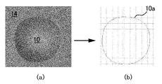
- the liquid on the substrate 14 forms a droplet 10 (see FIG. 5A), and the contact line 10a is obtained by the image analysis unit 30b (see FIG. 5B). .
- FIG. 6A shows the droplet 10 immediately after the repellent treatment
- FIG. 6B shows the droplet 10 after 30 minutes.
- the contact line 10a of the droplet 10 immediately after the repellent treatment is close to a perfect circle, but after a lapse of time, the contact line 10a was an irregular circle.
- FIG. 7 shows the result of plotting the contact angle along the contact line 10a of FIG. 6 counterclockwise from the starting point X.
- 6A corresponds to the curve 101
- FIG. 6B corresponds to the curve 102.
- the curve 102 fluctuated with a period of 700 microns.
- the fluctuating peaks and valleys corresponded to locations far from and close to the border between the repellent and repellent.
- the measurement was performed while increasing the amount of ultrapure water from 10 nl to 100 nl by 10 nl.
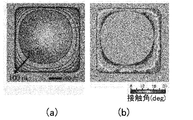
- FIG. 8A shows a change of the contact line 10 obtained from the contact line measurement unit 30, and FIG. 8B shows a mapping display of the contact angle distribution obtained by the simulation unit 40.
- FIG. Here, a two-dimensional image is obtained by linearly interpolating calculated values between intermittent contact lines 10 given by intermittent changes in the amount of ultrapure water in increments of 10 nl. By obtaining such an output, mapping measurement of surface free energy (wetting property) becomes possible.
Landscapes
- Physics & Mathematics (AREA)
- Health & Medical Sciences (AREA)
- Life Sciences & Earth Sciences (AREA)
- Chemical & Material Sciences (AREA)
- Analytical Chemistry (AREA)
- Biochemistry (AREA)
- General Health & Medical Sciences (AREA)
- General Physics & Mathematics (AREA)
- Immunology (AREA)
- Pathology (AREA)
- Length Measuring Devices By Optical Means (AREA)
Abstract
液体を基板上に滴下して形成される液滴の周囲に沿った接触角分布の測定方法及びこれを用いた装置の提供。 液滴を光学的に撮像し画像解析によって閉曲線からなる接触線を決定し、この接触線の内側に所定量の液体を配置したときの液滴形状をシミュレートし、接触線に沿った液滴の接触角分布を与える。
Description
本発明は、液体を基板上に滴下して形成される液滴の接触角の測定方法及びこれを用いた装置に関し、特に、基板表面上の接触角分布の測定方法及びこれを用いた装置に関する。
液体を基板上に滴下して形成される液滴の接触角を測定する装置が知られている。かかる装置では、一般的に、所定の光を照射した液滴を真横から撮像して基板表面及び液滴の撮影画像を得た上で、画像処理を利用して撮影画像を加工しながら、基板表面に対する液滴の接触角を直接的に測定している。
例えば、特許文献1では、上記したような基板表面及び液滴の撮影画像において、反射及び屈折によって現実の基板表面とは異なる位置に見かけ上の基板表面が出現し、この画像処理が必要になることを述べている。通常の接触角測定装置と同様に、光源ユニットによって基板の表面に光を照射しつつ、カメラユニットによって基板の表面を水平方向から撮像する。ここで、基板上の液滴とともにその近傍に空気の接触点を判別するための基準となる接触点判別部材を配置し、これを合わせて撮像することを開示している。この接触点判別部材を含んだ撮影画像に基づいて、接触点、すなわち、基板表面と液滴の境界面を判断できるので、当該境界面を基準として液滴の接触角を算出できるとしている。
また、所定量の液体を基板上に滴下して形成される液滴において、基板との接触線を撮像し、液滴が球体や楕円回転体の一部であると仮定した幾何学的計算によって接触角を与える装置も知られている。
例えば、特許文献2では、所定量の液体を基板上に滴下して形成される液滴の基板表面への接触面の接触面積を測定し、液滴の形状を球体であると仮定した上で、液滴の体積と接触面積から液滴の平均接触角を算出することを開示している。液滴の体積と接触面積を測定するのみで液滴の接触角を測定できるから、接触角が80度以下の親水性の強い場合でも接触角の測定を簡易且つ高い信頼性で行い得ると述べている。
ところで、基板上に滴下した液体のぬれ性について、基板と液体との接触角に基づく評価が行われている。ここで、例えば、プリンテッドエレクトロニクスのようなミクロンオーダーの直径の微小液滴を扱う工業分野では、その液滴の大きさが小さく、接触角が基板表面上の均一性に大きく影響されるとともに、液滴形状を横方向から観察すること自体が困難となる。
また、親水性/疎水性パターンによって微小液滴の形状を制御する試みも多くなされているが、かかる場合においても、同様に、液滴の観察が困難である。そこで、このような分野のぬれ性の評価にはシミュレーションが多く利用されている。
また、親水性/疎水性パターンによって微小液滴の形状を制御する試みも多くなされているが、かかる場合においても、同様に、液滴の観察が困難である。そこで、このような分野のぬれ性の評価にはシミュレーションが多く利用されている。
例えば、非特許文献1では、親水性/疎水性パターンを与えられた基板上での微小液滴の平衡形状シミュレーションについて述べられている。ここでは、液滴形状の決定において、液滴表面の固相/液相接触線の周囲では直接探索法により求めるとともに、液滴表面の他の部分では最急降下法により、これを求める「Hybrid Energy-Minimization(HEM)法」を提案している。これによれば、基板上での微小液滴のぬれ性についての正確な評価を与え得る。
Hiroyuki Matsui, Yuki Noda and Tatsuo Hasegawa, "Hybrid Energy-Minimization Simulation of Equilibrium Droplet Shapes on Hydrophilic/Hydrophobic Patterned Surfaces", Langmuir, 28 (44), pp.15450-15453, (2012)
特許文献1又は2による接触角の測定は、液滴の周囲における接触角の平均値(又は代表値)を与えている。ところで、液体を基板上に滴下して形成される液滴において、一般的に、基板表面の状態は微細形状及び付着物などによって不均一であるため、液滴の形状は真円ではなく、「いびつ」形状になる。そこで、基板上に滴下して形成される液滴の周囲における接触角の平均値(又は代表値)だけでなく、液滴の周囲に沿った接触角分布を測定することが求められる。
更に、液滴の表面上での接触角分布は、該表面の表面エネルギー分布を反映するため、これを求めることができれば、基板表面の汚染や触媒表面の評価、意図的な液滴ぬれ形状のデザイン、局所的な結晶成長制御など、多くの応用技術に適用され得る。このため、接触角の表面上の分布を精密且つ正確に測定することは重要である。
更に、液滴の表面上での接触角分布は、該表面の表面エネルギー分布を反映するため、これを求めることができれば、基板表面の汚染や触媒表面の評価、意図的な液滴ぬれ形状のデザイン、局所的な結晶成長制御など、多くの応用技術に適用され得る。このため、接触角の表面上の分布を精密且つ正確に測定することは重要である。
本発明は、以上のような状況に鑑みてなされたものであって、その目的とするところは、液体を基板上に滴下して形成される液滴の周囲に沿った接触角分布の測定方法及びこれを用いた装置の提供にある。
本発明による接触角分布測定方法は、所定量の液体を基板上に滴下して形成される液滴の周囲に沿った接触角分布を測定する方法であって、前記液滴を光学的に撮像し画像解析によって閉曲線からなる接触線を決定し、前記接触線の内側に前記所定量の前記液体を配置したときの液滴形状をシミュレートし、前記接触線に沿った前記液滴の接触角分布を与えることを特徴とする。
かかる発明によれば、基板表面の状態が不均一であっても、かかる不均一な状態は接触線の形状に反映されて測定されるため、これにより液滴形状をシミュレートし、接触線に沿った液滴の正確な接触角分布を得られるのである。故に、接触角分布に基づいた正確なぬれ性、ひいては表面エネルギーなどの物理特性の評価を与え得るのである。例えば、表面の汚染状態を視覚的に評価でき、逆に、ぬれ性を意図的に制御することで基板に付着する液滴形状をデザインすることなども可能になる。
上記した発明において、前記液滴形状のシミュレートは、前記接触線の内側及び外側の接触角をそれぞれ0度及び180度とし、仮想液滴形状を設定しつつ表面エネルギー分布から表面エネルギー和を算出するステップを繰り返し、前記表面エネルギー和を最低とする前記仮想液滴形状を前記液滴形状に決定することを特徴としてもよい。かかる発明によれば、接触線を固定した境界条件の下で繰り返し計算を行うことで、基板表面の不均一な状態に関わらず、液滴形状を簡便にシミュレートできて、接触線に沿った液滴の正確な接触角分布を得られる。
上記した発明において、前記基板は光透過性を有し、前記基板の前記液体を配置された側と反対側から撮像することを特徴としてもよい。かかる発明によれば、簡便且つ正確に接触線を測定できて、基板表面の不均一な状態に関わらず、接触線に沿った液滴の接触角分布を得られる。故に、接触角分布に基づいた正確なぬれ性などの各種物理特性の評価を与え得るのである。
更に、本発明による接触角分布測定装置は、所定量の液体を基板上に滴下して形成される液滴の周囲に沿った接触角分布を測定する装置であって、前記液滴を光学的に撮像する撮像手段と、前記撮像手段からの信号を受け画像解析によって閉曲線からなる接触線を決定する画像解析手段と、前記画像解析手段で得られた前記接触線の内側に前記所定量の前記液体を配置したときの液滴形状をシミュレートするシミュレータと、前記シミュレータにより得られた前記液滴形状から前記接触線に沿った前記液滴の接触角分布を与える提示手段と、を含むことを特徴とする。
かかる発明によれば、基板表面の状態が不均一であっても、かかる不均一な状態は接触線の形状に反映されて測定されるため、これにより液滴形状をシミュレートし、接触線に沿った液滴の正確な接触角分布を得られるのである。故に、接触角分布に基づいた正確なぬれ性、ひいては表面エネルギーなどの物理特性の評価を与え得るのである。例えば、表面の汚染状態を視覚的に評価でき、逆に、ぬれ性を意図的に制御することで基板に付着する液滴形状をデザインすることなども可能になる。
上記した発明において、前記シミュレータは、前記接触線の内側及び外側の接触角をそれぞれ0度及び180度とし、仮想液滴形状を設定しつつ表面エネルギー分布から表面エネルギー和を算出するステップを繰り返し、前記表面エネルギー和を最低とする前記仮想液滴形状を前記液滴形状に決定することを特徴としてもよい。かかる発明によれば、接触線を固定した境界条件の下で繰り返し計算を行うことで、基板表面の不均一な状態に関わらず、液滴形状を簡便にシミュレートできて、接触線に沿った液滴の正確な接触角分布を得られる。
上記した発明において、前記基板は光透過性を有し、前記撮像手段は前記基板の前記液体を配置された側と反対側から撮像を行うことを特徴としてもよい。かかる発明によれば、簡便且つ正確に接触線を測定できて、基板表面の不均一な状態に関わらず、接触線に沿った液滴の接触角分布を得られる。故に、接触角分布に基づいた正確なぬれ性などの各種物理特性の評価を与え得るのである。
以下に、本発明による液滴の周囲に沿った接触角分布の測定装置の1つの実施例について、図1乃至4を用いて詳細を説明する。
まず、図1に示すように、本発明による接触角分布の測定方法は、液体を基板上に滴下して形成される液滴を実測し(S1)、基板との接触境界、すなわち、接触線を抽出する(S2)。次に、接触線から液滴形状をシミュレートし(S3)、液滴の周囲に沿った接触角分布を与える(S4)のである。つまり、直接、液滴の接触角及びその分布を測定するのではなく、接触線だけを測定し、今度は、逆にこの接触線から液滴形状をシミュレートして液滴の接触角及びその分布を抽出するのである。ここで、シミュレーションは非特許文献1のような基板表面上の液滴形状の計算方法を用い得る。
図2に示すように、接触角分布測定装置1は、主たる構成部として、光学部30a及び画像解析部30bからなる接触線測定部30と、シミュレート部40と、出力装置部50とを含む。
図3を併せて参照すると、光学部30aは、透明な基板14の上面に向けて光束を照射する光源12と、基板14の下面から光源12へ光軸を向けて撮像可能なデジタルスチルカメラ若しくはデジタルビデオカメラからなる撮像手段21とを含む。すなわち、基板14の上面に液体を滴下して形成される液滴10を基板14の下方から撮像手段21で撮像するのである。撮像手段21で撮像された画像信号は画像解析部30bに送信される。
なお、後述する液滴10の接触線10aを画像処理によって求め易いように、適宜、基板14と撮像手段21との光学経路に所与の光学フィルタ手段を与え得る。また、基板14の上の液滴10の接触線10aを抽出する目的においては、光源12、基板14、撮像手段21の位置関係、及び、基板14が透明であることは、適宜、変更し得る。例えば、光源12及び撮像手段21はともに基板14の液滴10の配置側に位置していてもよい。かかる場合、基板14の光透過性に依存することなく測定ができて好ましい。
画像解析部30bでは、撮像手段21からの信号を受けて液滴10の基板14との交線としての閉曲線からなる接触線10aを抽出する。画像解析処理によって接触線10aを抽出する方法はこれに限定されるものではないが、画像データ取得部31で受信した画像データを画像加工部32で所定の閾値(コントラスト)を設定して二値化し、画像解析部33で接触線10aの形状を抽出するのである。
基板14の上の液滴10は基板14の表面状態によって接触線10aの形状を変える。すなわち、接触線10aの形状は必ずしも円形や楕円ではなく、また時間とともに変化し得るのである。
次に、シミュレート部40では、画像解析部30bで得られた接触線10aと、あらかじめ入力される液滴10に関する物理量を用いて、コンピュータ・シミュレーションによる液滴形状のシミュレートを行う。かかるシミュレーションもこれに限定されるものではないが、上記した非特許文献1の表面エネルギー分布の見積りを可能にする非特許文献1に記載されたHEM法を用いることが好適であるが、最急降下法などによるその他の計算方法を用いてもよい。
まず、データ入力部41では、少なくとも、液滴10を形成するのに要した液体の量、すなわち、液滴10の体積、及び、液滴10を構成する液体の表面張力の外部入力を求める。必要に応じて、液体の密度(重力を考慮するとき)などの外部入力を求めてもよい。また、後述する有限要素(FEM)計算部42におけるメッシュの条件の外部入力も受け付ける。
有限要素(FEM)計算部42では、データ入力部41により入力された値に基づき、仮想液滴の表面エネルギー分布を有限要素(FEM)法によって計算し、表面エネルギー和が最も小さくなる仮想液滴形状、すなわち、最安定形状を液滴10の計算形状として決定する。
詳細には、図4に示すように、画像解析部30bで抽出された接触線10aを親水性/疎水性領域の境界線として、接触線10aの内側の親水性領域14aでは接触角を0度、接触線10aの外側の疎水性領域10bでは接触角を180度と定義する。かかる条件において、データ入力部41で入力された液滴10の体積を有する仮想液滴10を接触線10aの内側、つまり親水性領域14a上に配置し、その表面形状に沿ってメッシュを設定し表面エネルギー分布を計算する。かかる表面エネルギー分布から表面エネルギー和を算出できて、繰り返し計算により、この和の最も小さい仮想液滴形状を液滴10の計算形状に設定するのである。
出力装置部50では、液滴10の計算形状に基づいて、接触線10aに沿った局所的な接触角の分布を0度~180度の範囲で出力する。すなわち、接触角分布データ出力部51において、シミュレート部40において得られた液滴10の計算形状について、閉曲線である接触線10aに沿って所定位置から周回させて、一定の間隔距離毎に接触角をサンプリングし出力するのである。
以上、述べてきた実施例によれば、例えば、基板14の表面の状態が不均一であっても、かかる不均一な表面状態は、光学部30aで撮像される接触線10aの形状に反映される。これに基づいて液滴形状をシミュレート部40でシミュレートすることで、接触線10aに沿った液滴の正確な接触角分布を得られるのである。故に、かかる接触角分布に基づいて、正確なぬれ性などの各種物理特性の評価を与え得るのである。また、混合液体、例えば、コロイドや多成分系などであっても、表面張力や密度が均一であり、測定可能若しくは既知であれば、本実施例による測定方法の適用が可能である。
[測定例]
次に、実際の測定例について、説明する。
次に、実際の測定例について、説明する。
ここでは、基板14に石英基板、液体に超純水を用い、10nlを滴下したときの液滴の接触線分布について測定した。なお、超純水は、密度1g/ml、表面張力72mN/mとした。また、測定は、基板14をUV/オゾンで親撥処理を行った直後、及び、30分の経過後の2回について行った。
まず、図5に示すように、基板14上の液体は液滴10を形成し(図5(a)参照)、画像解析部30bによって接触線10aが得られた(図5(b)参照)。
また、図6の(a)は親撥処理直後、(b)は30分経過後の液滴10である。これからわかるように、親撥処理を行った直後の液滴10の接触線10aは真円に近いのに対し、時間経過後には、いびつな円になっていた。
図7には、図6の接触線10aについて、始点Xから反時計回りに、これに沿って接触角をプロットした結果を示す。図6(a)は曲線101、(b)は曲線102に対応する。これによると、曲線102は700ミクロン周期で変動していた。主として、変動の山と谷は親撥境界からそれぞれ遠い箇所、近い箇所に対応していた。
また、上記したと同様の測定について、超純水の量を10nlから100nlまで10nlずつ増やしながら測定を行った。
図8の(a)は接触線測定部30から得られる接触線10の変化、(b)はシミュレート部40で得られる接触角分布をマッピング表示したものである。なお、ここでは10nlずつの超純水の断続的な量の変化によって与えられる断続的な接触線10間の計算値を線形補間して二次元画像を得ている。このような出力を得ることで、表面自由エネルギー(ぬれ性)のマッピング測定が可能となる。
以上、本発明による実施例及びこれに基づく変形例を説明したが、本発明は必ずしもこれに限定されるものではなく、当業者であれば、本発明の主旨又は添付した特許請求の範囲を逸脱することなく、様々な代替実施例及び改変例を見出すことができるであろう。
1 接触角分布測定装置
10 液滴
10a 接触線
12 光源
14 基板
21 撮像手段
30 接触線測定部
30a 光学部
30b 画像解析部
40 シミュレート部
50 出力装置部
10 液滴
10a 接触線
12 光源
14 基板
21 撮像手段
30 接触線測定部
30a 光学部
30b 画像解析部
40 シミュレート部
50 出力装置部
Claims (6)
- 所定量の液体を基板上に滴下して形成される液滴の周囲に沿った接触角分布を測定する方法であって、前記液滴を光学的に撮像し画像解析によって閉曲線からなる接触線を決定し、前記接触線の内側に前記所定量の前記液体を配置したときの液滴形状をシミュレートし、前記接触線に沿った前記液滴の接触角分布を与えることを特徴とする液滴の接触角分布測定方法。
- 前記液滴形状のシミュレートは、前記接触線の内側及び外側の接触角をそれぞれ0度及び180度とし、仮想液滴形状を設定しつつ表面エネルギー分布から表面エネルギー和を算出するステップを繰り返し、前記表面エネルギー和を最低とする前記仮想液滴形状を前記液滴形状に決定することを特徴とする請求項1記載の液滴の接触角分布測定方法。
- 前記基板は光透過性を有し、前記基板の前記液体を配置された側と反対側から撮像することを特徴とする請求項1又は2に記載の接触角分布測定方法。
- 所定量の液体を基板上に滴下して形成される液滴の周囲に沿った接触角分布を測定する装置であって、
前記液滴を光学的に撮像する撮像手段と、
前記撮像手段からの信号を受け画像解析によって閉曲線からなる接触線を決定する画像解析手段と、
前記画像解析手段で得られた前記接触線の内側に前記所定量の前記液体を配置したときの液滴形状をシミュレートするシミュレータと、
前記シミュレータにより得られた前記液滴形状から前記接触線に沿った前記液滴の接触角分布を与える提示手段と、を含むことを特徴とする液滴の接触角分布測定装置。 - 前記シミュレータは、前記接触線の内側及び外側の接触角をそれぞれ0度及び180度とし、仮想液滴形状を設定しつつ表面エネルギー分布から表面エネルギー和を算出するステップを繰り返し、前記表面エネルギー和を最低とする前記仮想液滴形状を前記液滴形状に決定することを特徴とする請求項4記載の接触角分布測定装置。
- 前記基板は光透過性を有し、前記撮像手段は前記基板の前記液体を配置された側と反対側から撮像を行うことを特徴とする請求項4又は5に記載の接触角分布測定装置。
Priority Applications (1)
| Application Number | Priority Date | Filing Date | Title |
|---|---|---|---|
| JP2015529516A JP6120341B2 (ja) | 2013-07-29 | 2014-07-18 | 液滴の接触角分布測定方法及びこれを用いた装置 |
Applications Claiming Priority (2)
| Application Number | Priority Date | Filing Date | Title |
|---|---|---|---|
| JP2013156745 | 2013-07-29 | ||
| JP2013-156745 | 2013-07-29 |
Publications (1)
| Publication Number | Publication Date |
|---|---|
| WO2015016083A1 true WO2015016083A1 (ja) | 2015-02-05 |
Family
ID=52431621
Family Applications (1)
| Application Number | Title | Priority Date | Filing Date |
|---|---|---|---|
| PCT/JP2014/069160 Ceased WO2015016083A1 (ja) | 2013-07-29 | 2014-07-18 | 液滴の接触角分布測定方法及びこれを用いた装置 |
Country Status (2)
| Country | Link |
|---|---|
| JP (1) | JP6120341B2 (ja) |
| WO (1) | WO2015016083A1 (ja) |
Cited By (1)
| Publication number | Priority date | Publication date | Assignee | Title |
|---|---|---|---|---|
| CN106568690A (zh) * | 2016-11-08 | 2017-04-19 | 清华大学 | 固‑液界面作用势能函数的获取方法及系统 |
Family Cites Families (4)
| Publication number | Priority date | Publication date | Assignee | Title |
|---|---|---|---|---|
| JPH1015479A (ja) * | 1996-07-09 | 1998-01-20 | Matsushita Electric Ind Co Ltd | 自由表面を有する液体のシミュレーションの実行方法及びそれを用いた塗布方法 |
| JP2007093496A (ja) * | 2005-09-30 | 2007-04-12 | Hitachi High-Technologies Corp | 化学マイクロラボシステム |
| US8255194B2 (en) * | 2009-12-02 | 2012-08-28 | Seiko Epson Corporation | Judiciously retreated finite element method for solving lubrication equation |
| JP5480669B2 (ja) * | 2010-03-01 | 2014-04-23 | 協和界面科学株式会社 | 接触角計用画像処理装置および液滴の平面視輪郭形状導出方法 |
-
2014
- 2014-07-18 WO PCT/JP2014/069160 patent/WO2015016083A1/ja not_active Ceased
- 2014-07-18 JP JP2015529516A patent/JP6120341B2/ja not_active Expired - Fee Related
Non-Patent Citations (1)
| Title |
|---|
| YUKI NODA ET AL.: "Observation and simulation of microdroplet shapes on surface-energy-patterned substrates: Contact line engineering for printed electronics", JOURNAL OF APPLIED PHYSICS, vol. 114, 25 July 2013 (2013-07-25), pages 044905 * |
Cited By (1)
| Publication number | Priority date | Publication date | Assignee | Title |
|---|---|---|---|---|
| CN106568690A (zh) * | 2016-11-08 | 2017-04-19 | 清华大学 | 固‑液界面作用势能函数的获取方法及系统 |
Also Published As
| Publication number | Publication date |
|---|---|
| JP6120341B2 (ja) | 2017-04-26 |
| JPWO2015016083A1 (ja) | 2017-03-02 |
Similar Documents
| Publication | Publication Date | Title |
|---|---|---|
| Souzy et al. | Velocity distributions, dispersion and stretching in three-dimensional porous media | |
| Honkanen et al. | Digital imaging measurement of dense multiphase flows in industrial processes | |
| Harshani et al. | Experimental study of porous media flow using hydro-gel beads and LED based PIV | |
| Mathai et al. | Translational and rotational dynamics of a large buoyant sphere in turbulence | |
| JP6373986B2 (ja) | 液体検査用低コントラストの標準として使用される粒子懸濁液 | |
| JP6286291B2 (ja) | 画像処理装置、画像取得装置、画像処理方法および画像取得方法 | |
| RS61389B1 (sr) | Uređaj i postupak za analizu lomova | |
| Riefler et al. | Intercomparison of Inversion Algorithms for Particle‐Sizing Using Mie Scattering | |
| CN110455454A (zh) | 一种基于视觉的多阵列点三维力测量方法及其装置 | |
| JP7772067B2 (ja) | ガス濃度特徴量推定装置、ガス濃度特徴量推定方法、プログラム、およびガス濃度特徴量推論モデル生成装置 | |
| KR102035859B1 (ko) | 점도 측정 방법 | |
| JP6120341B2 (ja) | 液滴の接触角分布測定方法及びこれを用いた装置 | |
| Fleßner et al. | Determination of metrological structural resolution of a CT system using the frequency response on surface structures | |
| JP2010276540A (ja) | 生体組織表面解析装置、生体組織表面解析プログラム、および生体組織表面解析方法 | |
| CN103914695B (zh) | 一种用于微电泳图像识别装置及其方法 | |
| JP2010025692A (ja) | 抗原濃度検出装置及び抗原濃度検出方法 | |
| CN104463961A (zh) | 几何光学光线追迹仿真微粒衍射图方法 | |
| Sabbagh et al. | An imaging approach for in-situ measurement of refractive index of a porous medium | |
| CN114492240B (zh) | 一种红外气动光学成像仿真方法、存储介质及计算机设备 | |
| TWM543370U (zh) | 一種測試圖樣;以及檢測鏡頭用光箱 | |
| de la Torre et al. | Sizing of particles and droplets using 3D-PTV, an OpenPTV post-processing tool | |
| KR20040020915A (ko) | 밀도불균일 시료 해석방법, 그 장치 및 시스템 | |
| Meyer et al. | General cramér-von Mises, a helpful ally for transparent object inspection using deflection maps? | |
| Gunady et al. | A non-intrusive volumetric camera calibration system | |
| Noelle et al. | Calibrated bubble depth determination using a single camera |
Legal Events
| Date | Code | Title | Description |
|---|---|---|---|
| 121 | Ep: the epo has been informed by wipo that ep was designated in this application |
Ref document number: 14832890 Country of ref document: EP Kind code of ref document: A1 |
|
| ENP | Entry into the national phase |
Ref document number: 2015529516 Country of ref document: JP Kind code of ref document: A |
|
| NENP | Non-entry into the national phase |
Ref country code: DE |
|
| 122 | Ep: pct application non-entry in european phase |
Ref document number: 14832890 Country of ref document: EP Kind code of ref document: A1 |