WO2015014427A1 - Electro-optical device and the use thereof - Google Patents
Electro-optical device and the use thereof Download PDFInfo
- Publication number
- WO2015014427A1 WO2015014427A1 PCT/EP2014/001738 EP2014001738W WO2015014427A1 WO 2015014427 A1 WO2015014427 A1 WO 2015014427A1 EP 2014001738 W EP2014001738 W EP 2014001738W WO 2015014427 A1 WO2015014427 A1 WO 2015014427A1
- Authority
- WO
- WIPO (PCT)
- Prior art keywords
- emitter
- electro
- group
- optical device
- emitter layer
- Prior art date
Links
- 229920000642 polymer Polymers 0.000 claims abstract description 80
- 239000011368 organic material Substances 0.000 claims abstract description 9
- -1 Dihydrophenanthren- Chemical compound 0.000 claims description 36
- 125000003118 aryl group Chemical group 0.000 claims description 36
- 239000011159 matrix material Substances 0.000 claims description 26
- NIHNNTQXNPWCJQ-UHFFFAOYSA-N fluorene Chemical compound C1=CC=C2CC3=CC=CC=C3C2=C1 NIHNNTQXNPWCJQ-UHFFFAOYSA-N 0.000 claims description 22
- YNPNZTXNASCQKK-UHFFFAOYSA-N phenanthrene Chemical compound C1=CC=C2C3=CC=CC=C3C=CC2=C1 YNPNZTXNASCQKK-UHFFFAOYSA-N 0.000 claims description 17
- 230000003595 spectral effect Effects 0.000 claims description 16
- 125000001072 heteroaryl group Chemical group 0.000 claims description 15
- 238000004768 lowest unoccupied molecular orbital Methods 0.000 claims description 14
- 125000005259 triarylamine group Chemical group 0.000 claims description 14
- 229920001577 copolymer Polymers 0.000 claims description 12
- 125000004093 cyano group Chemical group *C#N 0.000 claims description 11
- ICPSWZFVWAPUKF-UHFFFAOYSA-N 1,1'-spirobi[fluorene] Chemical compound C1=CC=C2C=C3C4(C=5C(C6=CC=CC=C6C=5)=CC=C4)C=CC=C3C2=C1 ICPSWZFVWAPUKF-UHFFFAOYSA-N 0.000 claims description 10
- 125000000217 alkyl group Chemical group 0.000 claims description 10
- 125000003545 alkoxy group Chemical group 0.000 claims description 9
- 125000003808 silyl group Chemical group [H][Si]([H])([H])[*] 0.000 claims description 8
- 239000000758 substrate Substances 0.000 claims description 8
- 125000003710 aryl alkyl group Chemical group 0.000 claims description 7
- 239000002322 conducting polymer Substances 0.000 claims description 6
- 229920001940 conductive polymer Polymers 0.000 claims description 6
- TXCDCPKCNAJMEE-UHFFFAOYSA-N dibenzofuran Chemical compound C1=CC=C2C3=CC=CC=C3OC2=C1 TXCDCPKCNAJMEE-UHFFFAOYSA-N 0.000 claims description 6
- PJULCNAVAGQLAT-UHFFFAOYSA-N indeno[2,1-a]fluorene Chemical compound C1=CC=C2C=C3C4=CC5=CC=CC=C5C4=CC=C3C2=C1 PJULCNAVAGQLAT-UHFFFAOYSA-N 0.000 claims description 6
- 125000004453 alkoxycarbonyl group Chemical group 0.000 claims description 5
- XXPBFNVKTVJZKF-UHFFFAOYSA-N dihydrophenanthrene Natural products C1=CC=C2CCC3=CC=CC=C3C2=C1 XXPBFNVKTVJZKF-UHFFFAOYSA-N 0.000 claims description 5
- 125000005110 aryl thio group Chemical group 0.000 claims description 4
- 125000004104 aryloxy group Chemical group 0.000 claims description 4
- 125000003178 carboxy group Chemical group [H]OC(*)=O 0.000 claims description 4
- 125000000753 cycloalkyl group Chemical group 0.000 claims description 4
- 125000005843 halogen group Chemical group 0.000 claims description 4
- 125000002887 hydroxy group Chemical group [H]O* 0.000 claims description 4
- 238000002347 injection Methods 0.000 claims description 4
- 239000007924 injection Substances 0.000 claims description 4
- 125000000449 nitro group Chemical group [O-][N+](*)=O 0.000 claims description 4
- 239000002537 cosmetic Substances 0.000 claims description 2
- 230000001225 therapeutic effect Effects 0.000 claims description 2
- IYYZUPMFVPLQIF-ALWQSETLSA-N dibenzothiophene Chemical group C1=CC=CC=2[34S]C3=C(C=21)C=CC=C3 IYYZUPMFVPLQIF-ALWQSETLSA-N 0.000 claims 1
- OMPYLRYHMKMJLR-UHFFFAOYSA-N ethene;thiophene 1,1-dioxide Chemical compound C=C.O=S1(=O)C=CC=C1 OMPYLRYHMKMJLR-UHFFFAOYSA-N 0.000 claims 1
- 238000004519 manufacturing process Methods 0.000 abstract description 6
- 238000005401 electroluminescence Methods 0.000 abstract description 2
- 239000010410 layer Substances 0.000 description 108
- 239000011229 interlayer Substances 0.000 description 37
- 150000001875 compounds Chemical class 0.000 description 30
- 239000000463 material Substances 0.000 description 26
- 125000004432 carbon atom Chemical group C* 0.000 description 24
- 125000001424 substituent group Chemical group 0.000 description 24
- 229910052751 metal Inorganic materials 0.000 description 19
- 239000002184 metal Substances 0.000 description 19
- 229920000547 conjugated polymer Polymers 0.000 description 17
- 229910052757 nitrogen Inorganic materials 0.000 description 14
- BASFCYQUMIYNBI-UHFFFAOYSA-N platinum Chemical compound [Pt] BASFCYQUMIYNBI-UHFFFAOYSA-N 0.000 description 14
- 229910052741 iridium Inorganic materials 0.000 description 12
- 239000000243 solution Substances 0.000 description 11
- YTPLMLYBLZKORZ-UHFFFAOYSA-N Thiophene Chemical compound C=1C=CSC=1 YTPLMLYBLZKORZ-UHFFFAOYSA-N 0.000 description 10
- MWPLVEDNUUSJAV-UHFFFAOYSA-N anthracene Natural products C1=CC=CC2=CC3=CC=CC=C3C=C21 MWPLVEDNUUSJAV-UHFFFAOYSA-N 0.000 description 10
- 150000003254 radicals Chemical group 0.000 description 10
- 125000004435 hydrogen atom Chemical class [H]* 0.000 description 9
- RAXXELZNTBOGNW-UHFFFAOYSA-N imidazole Natural products C1=CNC=N1 RAXXELZNTBOGNW-UHFFFAOYSA-N 0.000 description 9
- GKOZUEZYRPOHIO-UHFFFAOYSA-N iridium atom Chemical compound [Ir] GKOZUEZYRPOHIO-UHFFFAOYSA-N 0.000 description 9
- 239000003446 ligand Substances 0.000 description 9
- 238000001228 spectrum Methods 0.000 description 9
- 150000001412 amines Chemical class 0.000 description 7
- 150000001454 anthracenes Chemical class 0.000 description 7
- BBEAQIROQSPTKN-UHFFFAOYSA-N antipyrene Natural products C1=CC=C2C=CC3=CC=CC4=CC=C1C2=C43 BBEAQIROQSPTKN-UHFFFAOYSA-N 0.000 description 7
- 230000015572 biosynthetic process Effects 0.000 description 7
- 229910052739 hydrogen Inorganic materials 0.000 description 7
- 150000002576 ketones Chemical class 0.000 description 7
- 238000000034 method Methods 0.000 description 7
- 238000003786 synthesis reaction Methods 0.000 description 7
- 229930192474 thiophene Natural products 0.000 description 7
- YXFVVABEGXRONW-UHFFFAOYSA-N Toluene Chemical compound CC1=CC=CC=C1 YXFVVABEGXRONW-UHFFFAOYSA-N 0.000 description 6
- 125000004429 atom Chemical group 0.000 description 6
- AIXAANGOTKPUOY-UHFFFAOYSA-N carbachol Chemical group [Cl-].C[N+](C)(C)CCOC(N)=O AIXAANGOTKPUOY-UHFFFAOYSA-N 0.000 description 6
- 238000001194 electroluminescence spectrum Methods 0.000 description 6
- 125000005842 heteroatom Chemical group 0.000 description 6
- 125000001183 hydrocarbyl group Chemical group 0.000 description 6
- 125000002080 perylenyl group Chemical group C1(=CC=C2C=CC=C3C4=CC=CC5=CC=CC(C1=C23)=C45)* 0.000 description 6
- POILWHVDKZOXJZ-ARJAWSKDSA-M (z)-4-oxopent-2-en-2-olate Chemical compound C\C([O-])=C\C(C)=O POILWHVDKZOXJZ-ARJAWSKDSA-M 0.000 description 5
- DXBHBZVCASKNBY-UHFFFAOYSA-N 1,2-Benz(a)anthracene Chemical class C1=CC=C2C3=CC4=CC=CC=C4C=C3C=CC2=C1 DXBHBZVCASKNBY-UHFFFAOYSA-N 0.000 description 5
- UWRZIZXBOLBCON-UHFFFAOYSA-N 2-phenylethenamine Chemical class NC=CC1=CC=CC=C1 UWRZIZXBOLBCON-UHFFFAOYSA-N 0.000 description 5
- WDECIBYCCFPHNR-UHFFFAOYSA-N Chrysene Natural products C1=CC=CC2=CC=C3C4=CC=CC=C4C=CC3=C21 WDECIBYCCFPHNR-UHFFFAOYSA-N 0.000 description 5
- 150000004982 aromatic amines Chemical class 0.000 description 5
- 150000001716 carbazoles Chemical class 0.000 description 5
- 150000004696 coordination complex Chemical class 0.000 description 5
- 229910052731 fluorine Inorganic materials 0.000 description 5
- 229910052736 halogen Inorganic materials 0.000 description 5
- 150000002367 halogens Chemical class 0.000 description 5
- 239000001257 hydrogen Substances 0.000 description 5
- 239000000203 mixture Substances 0.000 description 5
- MPQXHAGKBWFSNV-UHFFFAOYSA-N oxidophosphanium Chemical group [PH3]=O MPQXHAGKBWFSNV-UHFFFAOYSA-N 0.000 description 5
- 229910052763 palladium Inorganic materials 0.000 description 5
- 229910052697 platinum Inorganic materials 0.000 description 5
- 229920003227 poly(N-vinyl carbazole) Polymers 0.000 description 5
- 125000005504 styryl group Chemical group 0.000 description 5
- 229910052717 sulfur Inorganic materials 0.000 description 5
- 230000007704 transition Effects 0.000 description 5
- HYZJCKYKOHLVJF-UHFFFAOYSA-N 1H-benzimidazole Chemical compound C1=CC=C2NC=NC2=C1 HYZJCKYKOHLVJF-UHFFFAOYSA-N 0.000 description 4
- UJOBWOGCFQCDNV-UHFFFAOYSA-N 9H-carbazole Chemical compound C1=CC=C2C3=CC=CC=C3NC2=C1 UJOBWOGCFQCDNV-UHFFFAOYSA-N 0.000 description 4
- 0 CC(C(*)=C(*C(**)=C(*)*1)C1=C(*)N)N Chemical compound CC(C(*)=C(*C(**)=C(*)*1)C1=C(*)N)N 0.000 description 4
- PAYRUJLWNCNPSJ-UHFFFAOYSA-N N-phenyl amine Natural products NC1=CC=CC=C1 PAYRUJLWNCNPSJ-UHFFFAOYSA-N 0.000 description 4
- KAESVJOAVNADME-UHFFFAOYSA-N Pyrrole Chemical compound C=1C=CNC=1 KAESVJOAVNADME-UHFFFAOYSA-N 0.000 description 4
- 229910005965 SO 2 Inorganic materials 0.000 description 4
- 125000005577 anthracene group Chemical group 0.000 description 4
- IOJUPLGTWVMSFF-UHFFFAOYSA-N benzothiazole Chemical compound C1=CC=C2SC=NC2=C1 IOJUPLGTWVMSFF-UHFFFAOYSA-N 0.000 description 4
- VPUGDVKSAQVFFS-UHFFFAOYSA-N coronene Chemical compound C1=C(C2=C34)C=CC3=CC=C(C=C3)C4=C4C3=CC=C(C=C3)C4=C2C3=C1 VPUGDVKSAQVFFS-UHFFFAOYSA-N 0.000 description 4
- 238000004132 cross linking Methods 0.000 description 4
- GVEPBJHOBDJJJI-UHFFFAOYSA-N fluoranthrene Natural products C1=CC(C2=CC=CC=C22)=C3C2=CC=CC3=C1 GVEPBJHOBDJJJI-UHFFFAOYSA-N 0.000 description 4
- 230000005525 hole transport Effects 0.000 description 4
- 150000002739 metals Chemical class 0.000 description 4
- 125000002950 monocyclic group Chemical group 0.000 description 4
- 229910052762 osmium Inorganic materials 0.000 description 4
- 229910052760 oxygen Inorganic materials 0.000 description 4
- CSHWQDPOILHKBI-UHFFFAOYSA-N peryrene Natural products C1=CC(C2=CC=CC=3C2=C2C=CC=3)=C3C2=CC=CC3=C1 CSHWQDPOILHKBI-UHFFFAOYSA-N 0.000 description 4
- 229920000123 polythiophene Polymers 0.000 description 4
- 125000004076 pyridyl group Chemical group 0.000 description 4
- 230000005855 radiation Effects 0.000 description 4
- YYMBJDOZVAITBP-UHFFFAOYSA-N rubrene Chemical class C1=CC=CC=C1C(C1=C(C=2C=CC=CC=2)C2=CC=CC=C2C(C=2C=CC=CC=2)=C11)=C(C=CC=C2)C2=C1C1=CC=CC=C1 YYMBJDOZVAITBP-UHFFFAOYSA-N 0.000 description 4
- 150000003384 small molecules Chemical class 0.000 description 4
- 239000000126 substance Substances 0.000 description 4
- 150000003462 sulfoxides Chemical class 0.000 description 4
- 229910052723 transition metal Inorganic materials 0.000 description 4
- 150000003624 transition metals Chemical class 0.000 description 4
- 125000003837 (C1-C20) alkyl group Chemical group 0.000 description 3
- UWRZIZXBOLBCON-VOTSOKGWSA-N (e)-2-phenylethenamine Chemical class N\C=C\C1=CC=CC=C1 UWRZIZXBOLBCON-VOTSOKGWSA-N 0.000 description 3
- JYEUMXHLPRZUAT-UHFFFAOYSA-N 1,2,3-triazine Chemical compound C1=CN=NN=C1 JYEUMXHLPRZUAT-UHFFFAOYSA-N 0.000 description 3
- UHOVQNZJYSORNB-UHFFFAOYSA-N Benzene Chemical compound C1=CC=CC=C1 UHOVQNZJYSORNB-UHFFFAOYSA-N 0.000 description 3
- 239000007983 Tris buffer Substances 0.000 description 3
- 229910052801 chlorine Inorganic materials 0.000 description 3
- 239000000460 chlorine Substances 0.000 description 3
- 125000004122 cyclic group Chemical group 0.000 description 3
- 125000004986 diarylamino group Chemical group 0.000 description 3
- 125000003983 fluorenyl group Chemical group C1(=CC=CC=2C3=CC=CC=C3CC12)* 0.000 description 3
- 150000002460 imidazoles Chemical class 0.000 description 3
- 239000011261 inert gas Substances 0.000 description 3
- 238000007641 inkjet printing Methods 0.000 description 3
- MILUBEOXRNEUHS-UHFFFAOYSA-N iridium(3+) Chemical compound [Ir+3] MILUBEOXRNEUHS-UHFFFAOYSA-N 0.000 description 3
- 229910052747 lanthanoid Inorganic materials 0.000 description 3
- 150000002602 lanthanoids Chemical class 0.000 description 3
- 238000005259 measurement Methods 0.000 description 3
- IJGRMHOSHXDMSA-UHFFFAOYSA-N nitrogen Substances N#N IJGRMHOSHXDMSA-UHFFFAOYSA-N 0.000 description 3
- 229920000548 poly(silane) polymer Polymers 0.000 description 3
- 238000002360 preparation method Methods 0.000 description 3
- 238000007639 printing Methods 0.000 description 3
- 230000008569 process Effects 0.000 description 3
- 125000005493 quinolyl group Chemical group 0.000 description 3
- 229910052703 rhodium Inorganic materials 0.000 description 3
- 229910052707 ruthenium Inorganic materials 0.000 description 3
- 238000004528 spin coating Methods 0.000 description 3
- 150000003518 tetracenes Chemical class 0.000 description 3
- 238000012546 transfer Methods 0.000 description 3
- 125000004169 (C1-C6) alkyl group Chemical group 0.000 description 2
- BCMCBBGGLRIHSE-UHFFFAOYSA-N 1,3-benzoxazole Chemical compound C1=CC=C2OC=NC2=C1 BCMCBBGGLRIHSE-UHFFFAOYSA-N 0.000 description 2
- OZKOMUDCMCEDTM-UHFFFAOYSA-N 1,7-phenanthroline Chemical group C1=CC=C2C3=NC=CC=C3C=CC2=N1 OZKOMUDCMCEDTM-UHFFFAOYSA-N 0.000 description 2
- UHXOHPVVEHBKKT-UHFFFAOYSA-N 1-(2,2-diphenylethenyl)-4-[4-(2,2-diphenylethenyl)phenyl]benzene Chemical group C=1C=C(C=2C=CC(C=C(C=3C=CC=CC=3)C=3C=CC=CC=3)=CC=2)C=CC=1C=C(C=1C=CC=CC=1)C1=CC=CC=C1 UHXOHPVVEHBKKT-UHFFFAOYSA-N 0.000 description 2
- VERMWGQSKPXSPZ-BUHFOSPRSA-N 1-[(e)-2-phenylethenyl]anthracene Chemical class C=1C=CC2=CC3=CC=CC=C3C=C2C=1\C=C\C1=CC=CC=C1 VERMWGQSKPXSPZ-BUHFOSPRSA-N 0.000 description 2
- FCEHBMOGCRZNNI-UHFFFAOYSA-N 1-benzothiophene Chemical compound C1=CC=C2SC=CC2=C1 FCEHBMOGCRZNNI-UHFFFAOYSA-N 0.000 description 2
- GEQBRULPNIVQPP-UHFFFAOYSA-N 2-[3,5-bis(1-phenylbenzimidazol-2-yl)phenyl]-1-phenylbenzimidazole Chemical compound C1=CC=CC=C1N1C2=CC=CC=C2N=C1C1=CC(C=2N(C3=CC=CC=C3N=2)C=2C=CC=CC=2)=CC(C=2N(C3=CC=CC=C3N=2)C=2C=CC=CC=2)=C1 GEQBRULPNIVQPP-UHFFFAOYSA-N 0.000 description 2
- ZOKIJILZFXPFTO-UHFFFAOYSA-N 4-methyl-n-[4-[1-[4-(4-methyl-n-(4-methylphenyl)anilino)phenyl]cyclohexyl]phenyl]-n-(4-methylphenyl)aniline Chemical compound C1=CC(C)=CC=C1N(C=1C=CC(=CC=1)C1(CCCCC1)C=1C=CC(=CC=1)N(C=1C=CC(C)=CC=1)C=1C=CC(C)=CC=1)C1=CC=C(C)C=C1 ZOKIJILZFXPFTO-UHFFFAOYSA-N 0.000 description 2
- 239000005725 8-Hydroxyquinoline Substances 0.000 description 2
- XKRFYHLGVUSROY-UHFFFAOYSA-N Argon Chemical compound [Ar] XKRFYHLGVUSROY-UHFFFAOYSA-N 0.000 description 2
- 229910052693 Europium Inorganic materials 0.000 description 2
- PXGOKWXKJXAPGV-UHFFFAOYSA-N Fluorine Chemical compound FF PXGOKWXKJXAPGV-UHFFFAOYSA-N 0.000 description 2
- UFWIBTONFRDIAS-UHFFFAOYSA-N Naphthalene Chemical compound C1=CC=CC2=CC=CC=C21 UFWIBTONFRDIAS-UHFFFAOYSA-N 0.000 description 2
- XYFCBTPGUUZFHI-UHFFFAOYSA-N Phosphine Chemical compound P XYFCBTPGUUZFHI-UHFFFAOYSA-N 0.000 description 2
- 229920000265 Polyparaphenylene Polymers 0.000 description 2
- KYQCOXFCLRTKLS-UHFFFAOYSA-N Pyrazine Chemical compound C1=CN=CC=N1 KYQCOXFCLRTKLS-UHFFFAOYSA-N 0.000 description 2
- NRCMAYZCPIVABH-UHFFFAOYSA-N Quinacridone Chemical compound N1C2=CC=CC=C2C(=O)C2=C1C=C1C(=O)C3=CC=CC=C3NC1=C2 NRCMAYZCPIVABH-UHFFFAOYSA-N 0.000 description 2
- SMWDFEZZVXVKRB-UHFFFAOYSA-N Quinoline Chemical compound N1=CC=CC2=CC=CC=C21 SMWDFEZZVXVKRB-UHFFFAOYSA-N 0.000 description 2
- XBDYBAVJXHJMNQ-UHFFFAOYSA-N Tetrahydroanthracene Natural products C1=CC=C2C=C(CCCC3)C3=CC2=C1 XBDYBAVJXHJMNQ-UHFFFAOYSA-N 0.000 description 2
- 238000004833 X-ray photoelectron spectroscopy Methods 0.000 description 2
- 229910052768 actinide Inorganic materials 0.000 description 2
- 150000001255 actinides Chemical class 0.000 description 2
- 229910052782 aluminium Inorganic materials 0.000 description 2
- 125000000732 arylene group Chemical group 0.000 description 2
- CUFNKYGDVFVPHO-UHFFFAOYSA-N azulene Chemical compound C1=CC=CC2=CC=CC2=C1 CUFNKYGDVFVPHO-UHFFFAOYSA-N 0.000 description 2
- 150000001556 benzimidazoles Chemical class 0.000 description 2
- RWCCWEUUXYIKHB-UHFFFAOYSA-N benzophenone Chemical compound C=1C=CC=CC=1C(=O)C1=CC=CC=C1 RWCCWEUUXYIKHB-UHFFFAOYSA-N 0.000 description 2
- 239000012965 benzophenone Substances 0.000 description 2
- 239000004305 biphenyl Substances 0.000 description 2
- 125000000319 biphenyl-4-yl group Chemical group [H]C1=C([H])C([H])=C([H])C([H])=C1C1=C([H])C([H])=C([*])C([H])=C1[H] 0.000 description 2
- 150000001642 boronic acid derivatives Chemical class 0.000 description 2
- 238000012512 characterization method Methods 0.000 description 2
- 238000010276 construction Methods 0.000 description 2
- 229910052802 copper Inorganic materials 0.000 description 2
- ZYGHJZDHTFUPRJ-UHFFFAOYSA-N coumarin Chemical compound C1=CC=C2OC(=O)C=CC2=C1 ZYGHJZDHTFUPRJ-UHFFFAOYSA-N 0.000 description 2
- 239000000412 dendrimer Substances 0.000 description 2
- 229920000736 dendritic polymer Polymers 0.000 description 2
- 238000011161 development Methods 0.000 description 2
- 230000018109 developmental process Effects 0.000 description 2
- XNKVIGSNRYAOQZ-UHFFFAOYSA-N dibenzofluorene Chemical compound C12=CC=CC=C2C2=CC=CC=C2C2=C1CC1=CC=CC=C12 XNKVIGSNRYAOQZ-UHFFFAOYSA-N 0.000 description 2
- IYYZUPMFVPLQIF-UHFFFAOYSA-N dibenzothiophene Chemical compound C1=CC=C2C3=CC=CC=C3SC2=C1 IYYZUPMFVPLQIF-UHFFFAOYSA-N 0.000 description 2
- BKMIWBZIQAAZBD-UHFFFAOYSA-N diindenoperylene Chemical compound C12=C3C4=CC=C2C2=CC=CC=C2C1=CC=C3C1=CC=C2C3=CC=CC=C3C3=CC=C4C1=C32 BKMIWBZIQAAZBD-UHFFFAOYSA-N 0.000 description 2
- ZUOUZKKEUPVFJK-UHFFFAOYSA-N diphenyl Chemical compound C1=CC=CC=C1C1=CC=CC=C1 ZUOUZKKEUPVFJK-UHFFFAOYSA-N 0.000 description 2
- 239000002019 doping agent Substances 0.000 description 2
- 150000008376 fluorenones Chemical class 0.000 description 2
- 239000011737 fluorine Substances 0.000 description 2
- 230000005283 ground state Effects 0.000 description 2
- WIAWDMBHXUZQGV-UHFFFAOYSA-N heptacyclo[13.10.1.12,6.011,26.017,25.018,23.010,27]heptacosa-1(25),2,4,6(27),7,9,11,13,15(26),17,19,21,23-tridecaene Chemical group C=12C3=CC=CC2=CC=CC=1C1=CC=CC2=C1C3=C1C=C3C=CC=CC3=C1C2 WIAWDMBHXUZQGV-UHFFFAOYSA-N 0.000 description 2
- 125000000623 heterocyclic group Chemical group 0.000 description 2
- 238000004770 highest occupied molecular orbital Methods 0.000 description 2
- 150000007857 hydrazones Chemical class 0.000 description 2
- 238000010348 incorporation Methods 0.000 description 2
- AMGQUBHHOARCQH-UHFFFAOYSA-N indium;oxotin Chemical compound [In].[Sn]=O AMGQUBHHOARCQH-UHFFFAOYSA-N 0.000 description 2
- 229940079865 intestinal antiinfectives imidazole derivative Drugs 0.000 description 2
- 229910052749 magnesium Inorganic materials 0.000 description 2
- 238000004776 molecular orbital Methods 0.000 description 2
- 229910052750 molybdenum Inorganic materials 0.000 description 2
- 230000005693 optoelectronics Effects 0.000 description 2
- 125000002524 organometallic group Chemical group 0.000 description 2
- 229960003540 oxyquinoline Drugs 0.000 description 2
- 125000005010 perfluoroalkyl group Chemical group 0.000 description 2
- 150000005041 phenanthrolines Chemical class 0.000 description 2
- 125000001997 phenyl group Chemical group [H]C1=C([H])C([H])=C(*)C([H])=C1[H] 0.000 description 2
- 125000000843 phenylene group Chemical group C1(=C(C=CC=C1)*)* 0.000 description 2
- 150000004986 phenylenediamines Chemical class 0.000 description 2
- IEQIEDJGQAUEQZ-UHFFFAOYSA-N phthalocyanine Chemical class N1C(N=C2C3=CC=CC=C3C(N=C3C4=CC=CC=C4C(=N4)N3)=N2)=C(C=CC=C2)C2=C1N=C1C2=CC=CC=C2C4=N1 IEQIEDJGQAUEQZ-UHFFFAOYSA-N 0.000 description 2
- 229920003229 poly(methyl methacrylate) Polymers 0.000 description 2
- 229920002037 poly(vinyl butyral) polymer Polymers 0.000 description 2
- 229920000767 polyaniline Polymers 0.000 description 2
- 229920001690 polydopamine Polymers 0.000 description 2
- 239000004926 polymethyl methacrylate Substances 0.000 description 2
- 150000004032 porphyrins Chemical class 0.000 description 2
- 150000003220 pyrenes Chemical class 0.000 description 2
- 150000003222 pyridines Chemical class 0.000 description 2
- 238000003077 quantum chemistry computational method Methods 0.000 description 2
- MCJGNVYPOGVAJF-UHFFFAOYSA-N quinolin-8-ol Chemical compound C1=CN=C2C(O)=CC=CC2=C1 MCJGNVYPOGVAJF-UHFFFAOYSA-N 0.000 description 2
- 125000002943 quinolinyl group Chemical group N1=C(C=CC2=CC=CC=C12)* 0.000 description 2
- 229910052702 rhenium Inorganic materials 0.000 description 2
- 239000004065 semiconductor Substances 0.000 description 2
- 150000004756 silanes Chemical class 0.000 description 2
- 229910052709 silver Inorganic materials 0.000 description 2
- 239000002904 solvent Substances 0.000 description 2
- 125000003003 spiro group Chemical group 0.000 description 2
- PJANXHGTPQOBST-UHFFFAOYSA-N stilbene Chemical class C=1C=CC=CC=1C=CC1=CC=CC=C1 PJANXHGTPQOBST-UHFFFAOYSA-N 0.000 description 2
- 125000003107 substituted aryl group Chemical group 0.000 description 2
- 150000003512 tertiary amines Chemical group 0.000 description 2
- 238000012360 testing method Methods 0.000 description 2
- IFLREYGFSNHWGE-UHFFFAOYSA-N tetracene Chemical compound C1=CC=CC2=CC3=CC4=CC=CC=C4C=C3C=C21 IFLREYGFSNHWGE-UHFFFAOYSA-N 0.000 description 2
- 125000004001 thioalkyl group Chemical group 0.000 description 2
- 150000003577 thiophenes Chemical class 0.000 description 2
- 125000002023 trifluoromethyl group Chemical group FC(F)(F)* 0.000 description 2
- 229910052721 tungsten Inorganic materials 0.000 description 2
- 238000004402 ultra-violet photoelectron spectroscopy Methods 0.000 description 2
- 238000007740 vapor deposition Methods 0.000 description 2
- 238000001429 visible spectrum Methods 0.000 description 2
- XLYOFNOQVPJJNP-UHFFFAOYSA-N water Chemical compound O XLYOFNOQVPJJNP-UHFFFAOYSA-N 0.000 description 2
- 229910052725 zinc Inorganic materials 0.000 description 2
- YGLVWOUNCXBPJF-UHFFFAOYSA-N (2,3,4,5-tetraphenylcyclopenta-1,4-dien-1-yl)benzene Chemical compound C1=CC=CC=C1C1C(C=2C=CC=CC=2)=C(C=2C=CC=CC=2)C(C=2C=CC=CC=2)=C1C1=CC=CC=C1 YGLVWOUNCXBPJF-UHFFFAOYSA-N 0.000 description 1
- JCXLYAWYOTYWKM-UHFFFAOYSA-N (2,3,4-triphenylcyclopenta-1,3-dien-1-yl)benzene Chemical compound C1C(C=2C=CC=CC=2)=C(C=2C=CC=CC=2)C(C=2C=CC=CC=2)=C1C1=CC=CC=C1 JCXLYAWYOTYWKM-UHFFFAOYSA-N 0.000 description 1
- DMDOIBWPFWJPQJ-ONEGZZNKSA-N (e)-2,3-bis(sulfanyl)but-2-enedinitrile Chemical compound N#CC(/S)=C(\S)C#N DMDOIBWPFWJPQJ-ONEGZZNKSA-N 0.000 description 1
- 150000005045 1,10-phenanthrolines Chemical class 0.000 description 1
- FIDRAVVQGKNYQK-UHFFFAOYSA-N 1,2,3,4-tetrahydrotriazine Chemical class C1NNNC=C1 FIDRAVVQGKNYQK-UHFFFAOYSA-N 0.000 description 1
- NGQSLSMAEVWNPU-YTEMWHBBSA-N 1,2-bis[(e)-2-phenylethenyl]benzene Chemical compound C=1C=CC=CC=1/C=C/C1=CC=CC=C1\C=C\C1=CC=CC=C1 NGQSLSMAEVWNPU-YTEMWHBBSA-N 0.000 description 1
- 150000005072 1,3,4-oxadiazoles Chemical class 0.000 description 1
- 150000000182 1,3,5-triazines Chemical class 0.000 description 1
- ZMLPKJYZRQZLDA-UHFFFAOYSA-N 1-(2-phenylethenyl)-4-[4-(2-phenylethenyl)phenyl]benzene Chemical group C=1C=CC=CC=1C=CC(C=C1)=CC=C1C(C=C1)=CC=C1C=CC1=CC=CC=C1 ZMLPKJYZRQZLDA-UHFFFAOYSA-N 0.000 description 1
- KMQPLEYEXDZOJF-UHFFFAOYSA-N 1-naphthalen-2-ylanthracene Chemical compound C1=CC=C2C=C3C(C4=CC5=CC=CC=C5C=C4)=CC=CC3=CC2=C1 KMQPLEYEXDZOJF-UHFFFAOYSA-N 0.000 description 1
- 125000001637 1-naphthyl group Chemical group [H]C1=C([H])C([H])=C2C(*)=C([H])C([H])=C([H])C2=C1[H] 0.000 description 1
- IVYAYAWSXINSEF-UHFFFAOYSA-N 1-tert-butylperylene Chemical group C1=CC(C=2C(C(C)(C)C)=CC=C3C=2C2=CC=C3)=C3C2=CC=CC3=C1 IVYAYAWSXINSEF-UHFFFAOYSA-N 0.000 description 1
- LPHIYKWSEYTCLW-UHFFFAOYSA-N 1h-azaborole Chemical class N1B=CC=C1 LPHIYKWSEYTCLW-UHFFFAOYSA-N 0.000 description 1
- PLJDGKPRGUMSAA-UHFFFAOYSA-N 2,2',7,7'-tetraphenyl-1,1'-spirobi[fluorene] Chemical compound C12=CC=C(C=3C=CC=CC=3)C=C2C=C(C23C(=CC=C4C5=CC=C(C=C5C=C43)C=3C=CC=CC=3)C=3C=CC=CC=3)C1=CC=C2C1=CC=CC=C1 PLJDGKPRGUMSAA-UHFFFAOYSA-N 0.000 description 1
- SULWTXOWAFVWOY-PHEQNACWSA-N 2,3-bis[(E)-2-phenylethenyl]pyrazine Chemical class C=1C=CC=CC=1/C=C/C1=NC=CN=C1\C=C\C1=CC=CC=C1 SULWTXOWAFVWOY-PHEQNACWSA-N 0.000 description 1
- MVWPVABZQQJTPL-UHFFFAOYSA-N 2,3-diphenylcyclohexa-2,5-diene-1,4-dione Chemical class O=C1C=CC(=O)C(C=2C=CC=CC=2)=C1C1=CC=CC=C1 MVWPVABZQQJTPL-UHFFFAOYSA-N 0.000 description 1
- DCEDTISGIDPBIP-UHFFFAOYSA-N 2-[2-[4-(2-thiophen-2-ylethenyl)phenyl]ethenyl]thiophene Chemical class C=1C=CSC=1C=CC(C=C1)=CC=C1C=CC1=CC=CS1 DCEDTISGIDPBIP-UHFFFAOYSA-N 0.000 description 1
- VLRSADZEDXVUPG-UHFFFAOYSA-N 2-naphthalen-1-ylpyridine Chemical class N1=CC=CC=C1C1=CC=CC2=CC=CC=C12 VLRSADZEDXVUPG-UHFFFAOYSA-N 0.000 description 1
- 125000001622 2-naphthyl group Chemical group [H]C1=C([H])C([H])=C2C([H])=C(*)C([H])=C([H])C2=C1[H] 0.000 description 1
- VQGHOUODWALEFC-UHFFFAOYSA-N 2-phenylpyridine Chemical compound C1=CC=CC=C1C1=CC=CC=N1 VQGHOUODWALEFC-UHFFFAOYSA-N 0.000 description 1
- 150000005360 2-phenylpyridines Chemical class 0.000 description 1
- FSEXLNMNADBYJU-UHFFFAOYSA-N 2-phenylquinoline Chemical class C1=CC=CC=C1C1=CC=C(C=CC=C2)C2=N1 FSEXLNMNADBYJU-UHFFFAOYSA-N 0.000 description 1
- KYGSXEYUWRFVNY-UHFFFAOYSA-N 2-pyran-2-ylidenepropanedinitrile Chemical compound N#CC(C#N)=C1OC=CC=C1 KYGSXEYUWRFVNY-UHFFFAOYSA-N 0.000 description 1
- QLPKTAFPRRIFQX-UHFFFAOYSA-N 2-thiophen-2-ylpyridine Chemical class C1=CSC(C=2N=CC=CC=2)=C1 QLPKTAFPRRIFQX-UHFFFAOYSA-N 0.000 description 1
- MGADZUXDNSDTHW-UHFFFAOYSA-N 2H-pyran Chemical compound C1OC=CC=C1 MGADZUXDNSDTHW-UHFFFAOYSA-N 0.000 description 1
- DMEVMYSQZPJFOK-UHFFFAOYSA-N 3,4,5,6,9,10-hexazatetracyclo[12.4.0.02,7.08,13]octadeca-1(18),2(7),3,5,8(13),9,11,14,16-nonaene Chemical group N1=NN=C2C3=CC=CC=C3C3=CC=NN=C3C2=N1 DMEVMYSQZPJFOK-UHFFFAOYSA-N 0.000 description 1
- GOLORTLGFDVFDW-UHFFFAOYSA-N 3-(1h-benzimidazol-2-yl)-7-(diethylamino)chromen-2-one Chemical compound C1=CC=C2NC(C3=CC4=CC=C(C=C4OC3=O)N(CC)CC)=NC2=C1 GOLORTLGFDVFDW-UHFFFAOYSA-N 0.000 description 1
- MCSXGCZMEPXKIW-UHFFFAOYSA-N 3-hydroxy-4-[(4-methyl-2-nitrophenyl)diazenyl]-N-(3-nitrophenyl)naphthalene-2-carboxamide Chemical compound Cc1ccc(N=Nc2c(O)c(cc3ccccc23)C(=O)Nc2cccc(c2)[N+]([O-])=O)c(c1)[N+]([O-])=O MCSXGCZMEPXKIW-UHFFFAOYSA-N 0.000 description 1
- XDFUNRTWHPWCKO-UHFFFAOYSA-N 4,5,9,10-tetrahydropyrene Chemical class C1CC2=CC=CC3=C2C2=C1C=CC=C2CC3 XDFUNRTWHPWCKO-UHFFFAOYSA-N 0.000 description 1
- WPCIUCNVWJNRCD-UHFFFAOYSA-N 4,5-dihydropyrene Chemical class C1=CC=C2CCC3=CC=CC4=CC=C1C2=C34 WPCIUCNVWJNRCD-UHFFFAOYSA-N 0.000 description 1
- AWXGSYPUMWKTBR-UHFFFAOYSA-N 4-carbazol-9-yl-n,n-bis(4-carbazol-9-ylphenyl)aniline Chemical compound C12=CC=CC=C2C2=CC=CC=C2N1C1=CC=C(N(C=2C=CC(=CC=2)N2C3=CC=CC=C3C3=CC=CC=C32)C=2C=CC(=CC=2)N2C3=CC=CC=C3C3=CC=CC=C32)C=C1 AWXGSYPUMWKTBR-UHFFFAOYSA-N 0.000 description 1
- AZFHXIBNMPIGOD-UHFFFAOYSA-N 4-hydroxypent-3-en-2-one iridium Chemical compound [Ir].CC(O)=CC(C)=O.CC(O)=CC(C)=O.CC(O)=CC(C)=O AZFHXIBNMPIGOD-UHFFFAOYSA-N 0.000 description 1
- LQYYDWJDEVKDGB-XPWSMXQVSA-N 4-methyl-n-[4-[(e)-2-[4-[(e)-2-[4-(4-methyl-n-(4-methylphenyl)anilino)phenyl]ethenyl]phenyl]ethenyl]phenyl]-n-(4-methylphenyl)aniline Chemical compound C1=CC(C)=CC=C1N(C=1C=CC(\C=C\C=2C=CC(\C=C\C=3C=CC(=CC=3)N(C=3C=CC(C)=CC=3)C=3C=CC(C)=CC=3)=CC=2)=CC=1)C1=CC=C(C)C=C1 LQYYDWJDEVKDGB-XPWSMXQVSA-N 0.000 description 1
- HPMDJLFQPKZBGR-UHFFFAOYSA-N 4-methyl-n-[4-[1-[4-(4-methyl-n-(4-methylphenyl)anilino)phenyl]-3-phenylpropyl]phenyl]-n-(4-methylphenyl)aniline Chemical compound C1=CC(C)=CC=C1N(C=1C=CC(=CC=1)C(CCC=1C=CC=CC=1)C=1C=CC(=CC=1)N(C=1C=CC(C)=CC=1)C=1C=CC(C)=CC=1)C1=CC=C(C)C=C1 HPMDJLFQPKZBGR-UHFFFAOYSA-N 0.000 description 1
- SCZWJXTUYYSKGF-UHFFFAOYSA-N 5,12-dimethylquinolino[2,3-b]acridine-7,14-dione Chemical compound CN1C2=CC=CC=C2C(=O)C2=C1C=C1C(=O)C3=CC=CC=C3N(C)C1=C2 SCZWJXTUYYSKGF-UHFFFAOYSA-N 0.000 description 1
- MZCJSUCRGWIKHH-UHFFFAOYSA-N 6,7-dihydrobenzo[d][1]benzoxepine Chemical class O1CCC2=CC=CC=C2C2=CC=CC=C21 MZCJSUCRGWIKHH-UHFFFAOYSA-N 0.000 description 1
- 150000004325 8-hydroxyquinolines Chemical class 0.000 description 1
- ZHBOFZNNPZNWGB-UHFFFAOYSA-N 9,10-bis(phenylethynyl)anthracene Chemical compound C1=CC=CC=C1C#CC(C1=CC=CC=C11)=C(C=CC=C2)C2=C1C#CC1=CC=CC=C1 ZHBOFZNNPZNWGB-UHFFFAOYSA-N 0.000 description 1
- FCNCGHJSNVOIKE-UHFFFAOYSA-N 9,10-diphenylanthracene Chemical compound C1=CC=CC=C1C(C1=CC=CC=C11)=C(C=CC=C2)C2=C1C1=CC=CC=C1 FCNCGHJSNVOIKE-UHFFFAOYSA-N 0.000 description 1
- SNFCXVRWFNAHQX-UHFFFAOYSA-N 9,9'-spirobi[fluorene] Chemical class C12=CC=CC=C2C2=CC=CC=C2C21C1=CC=CC=C1C1=CC=CC=C21 SNFCXVRWFNAHQX-UHFFFAOYSA-N 0.000 description 1
- LTUJKAYZIMMJEP-UHFFFAOYSA-N 9-[4-(4-carbazol-9-yl-2-methylphenyl)-3-methylphenyl]carbazole Chemical compound C12=CC=CC=C2C2=CC=CC=C2N1C1=CC=C(C=2C(=CC(=CC=2)N2C3=CC=CC=C3C3=CC=CC=C32)C)C(C)=C1 LTUJKAYZIMMJEP-UHFFFAOYSA-N 0.000 description 1
- ZHQCITRPEYURRL-UHFFFAOYSA-N 9-ethynyl-1-[4-(9-ethynylanthracen-1-yl)phenyl]anthracene Chemical compound C1=CC=C2C(C#C)=C3C(C4=CC=C(C=C4)C=4C=CC=C5C=C6C=CC=CC6=C(C=45)C#C)=CC=CC3=CC2=C1 ZHQCITRPEYURRL-UHFFFAOYSA-N 0.000 description 1
- ZYASLTYCYTYKFC-UHFFFAOYSA-N 9-methylidenefluorene Chemical class C1=CC=C2C(=C)C3=CC=CC=C3C2=C1 ZYASLTYCYTYKFC-UHFFFAOYSA-N 0.000 description 1
- GJCOSYZMQJWQCA-UHFFFAOYSA-N 9H-xanthene Chemical compound C1=CC=C2CC3=CC=CC=C3OC2=C1 GJCOSYZMQJWQCA-UHFFFAOYSA-N 0.000 description 1
- GDALETGZDYOOGB-UHFFFAOYSA-N Acridone Natural products C1=C(O)C=C2N(C)C3=CC=CC=C3C(=O)C2=C1O GDALETGZDYOOGB-UHFFFAOYSA-N 0.000 description 1
- HKMTVMBEALTRRR-UHFFFAOYSA-N Benzo[a]fluorene Chemical compound C1=CC=CC2=C3CC4=CC=CC=C4C3=CC=C21 HKMTVMBEALTRRR-UHFFFAOYSA-N 0.000 description 1
- ROFVEXUMMXZLPA-UHFFFAOYSA-N Bipyridyl Chemical group N1=CC=CC=C1C1=CC=CC=N1 ROFVEXUMMXZLPA-UHFFFAOYSA-N 0.000 description 1
- WKBOTKDWSSQWDR-UHFFFAOYSA-N Bromine atom Chemical class [Br] WKBOTKDWSSQWDR-UHFFFAOYSA-N 0.000 description 1
- KAKZBPTYRLMSJV-UHFFFAOYSA-N Butadiene Chemical class C=CC=C KAKZBPTYRLMSJV-UHFFFAOYSA-N 0.000 description 1
- KESRRRLHHXXBRW-UHFFFAOYSA-N C1=CC=NC2=C3C(O)=CC=CC3=CC=C21 Chemical compound C1=CC=NC2=C3C(O)=CC=CC3=CC=C21 KESRRRLHHXXBRW-UHFFFAOYSA-N 0.000 description 1
- ZAMOUSCENKQFHK-UHFFFAOYSA-N Chlorine atom Chemical compound [Cl] ZAMOUSCENKQFHK-UHFFFAOYSA-N 0.000 description 1
- 229910052692 Dysprosium Inorganic materials 0.000 description 1
- 229910052688 Gadolinium Inorganic materials 0.000 description 1
- 101000837344 Homo sapiens T-cell leukemia translocation-altered gene protein Proteins 0.000 description 1
- SIKJAQJRHWYJAI-UHFFFAOYSA-N Indole Chemical class C1=CC=C2NC=CC2=C1 SIKJAQJRHWYJAI-UHFFFAOYSA-N 0.000 description 1
- YHBTXTFFTYXOFV-UHFFFAOYSA-N Liquid thiophthene Chemical compound C1=CSC2=C1C=CS2 YHBTXTFFTYXOFV-UHFFFAOYSA-N 0.000 description 1
- LFABNOYDEODDFX-UHFFFAOYSA-N O=C(c(cc1)ccc1Br)c(cc1)ccc1Br Chemical compound O=C(c(cc1)ccc1Br)c(cc1)ccc1Br LFABNOYDEODDFX-UHFFFAOYSA-N 0.000 description 1
- CBENFWSGALASAD-UHFFFAOYSA-N Ozone Chemical compound [O-][O+]=O CBENFWSGALASAD-UHFFFAOYSA-N 0.000 description 1
- PCNDJXKNXGMECE-UHFFFAOYSA-N Phenazine Natural products C1=CC=CC2=NC3=CC=CC=C3N=C21 PCNDJXKNXGMECE-UHFFFAOYSA-N 0.000 description 1
- 239000004793 Polystyrene Substances 0.000 description 1
- 238000006069 Suzuki reaction reaction Methods 0.000 description 1
- 102100028692 T-cell leukemia translocation-altered gene protein Human genes 0.000 description 1
- 229910052771 Terbium Inorganic materials 0.000 description 1
- DGEZNRSVGBDHLK-UHFFFAOYSA-N [1,10]phenanthroline Chemical compound C1=CN=C2C3=NC=CC=C3C=CC2=C1 DGEZNRSVGBDHLK-UHFFFAOYSA-N 0.000 description 1
- VZWNSEBUFLQLBZ-UHFFFAOYSA-N [BH3-]c(cc1)ccc1N(c1ccc([BH+])cc1)c1ccc(C(C)CC)cc1 Chemical compound [BH3-]c(cc1)ccc1N(c1ccc([BH+])cc1)c1ccc(C(C)CC)cc1 VZWNSEBUFLQLBZ-UHFFFAOYSA-N 0.000 description 1
- GQVWHWAWLPCBHB-UHFFFAOYSA-L [Be](Oc1cccc2ccc(cccn3)c3c12)Oc1c2c3ncccc3ccc2ccc1 Chemical compound [Be](Oc1cccc2ccc(cccn3)c3c12)Oc1c2c3ncccc3ccc2ccc1 GQVWHWAWLPCBHB-UHFFFAOYSA-L 0.000 description 1
- XQNMMMZJPNTMIE-UHFFFAOYSA-N [Ir].C1(=CC(=CC=C1)C1=NC=CC(=C1)C(C)(C)C)C1=CC=CC=C1.C1(=CC(=CC=C1)C1=NC=CC(=C1)C(C)(C)C)C1=CC=CC=C1.C1(=CC(=CC=C1)C1=NC=CC(=C1)C(C)(C)C)C1=CC=CC=C1 Chemical compound [Ir].C1(=CC(=CC=C1)C1=NC=CC(=C1)C(C)(C)C)C1=CC=CC=C1.C1(=CC(=CC=C1)C1=NC=CC(=C1)C(C)(C)C)C1=CC=CC=C1.C1(=CC(=CC=C1)C1=NC=CC(=C1)C(C)(C)C)C1=CC=CC=C1 XQNMMMZJPNTMIE-UHFFFAOYSA-N 0.000 description 1
- CUJRVFIICFDLGR-UHFFFAOYSA-N acetylacetonate Chemical compound CC(=O)[CH-]C(C)=O CUJRVFIICFDLGR-UHFFFAOYSA-N 0.000 description 1
- FZEYVTFCMJSGMP-UHFFFAOYSA-N acridone Chemical compound C1=CC=C2C(=O)C3=CC=CC=C3NC2=C1 FZEYVTFCMJSGMP-UHFFFAOYSA-N 0.000 description 1
- 238000004026 adhesive bonding Methods 0.000 description 1
- 125000001931 aliphatic group Chemical group 0.000 description 1
- 125000005194 alkoxycarbonyloxy group Chemical group 0.000 description 1
- 125000002877 alkyl aryl group Chemical group 0.000 description 1
- 125000005196 alkyl carbonyloxy group Chemical group 0.000 description 1
- XAGFODPZIPBFFR-UHFFFAOYSA-N aluminium Chemical compound [Al] XAGFODPZIPBFFR-UHFFFAOYSA-N 0.000 description 1
- TVIVIEFSHFOWTE-UHFFFAOYSA-N aluminum;quinolin-8-ol Chemical compound [Al+3].C1=CN=C2C(O)=CC=CC2=C1.C1=CN=C2C(O)=CC=CC2=C1.C1=CN=C2C(O)=CC=CC2=C1 TVIVIEFSHFOWTE-UHFFFAOYSA-N 0.000 description 1
- IUFDZNVMARBLOJ-UHFFFAOYSA-K aluminum;quinoline-2-carboxylate Chemical compound [Al+3].C1=CC=CC2=NC(C(=O)[O-])=CC=C21.C1=CC=CC2=NC(C(=O)[O-])=CC=C21.C1=CC=CC2=NC(C(=O)[O-])=CC=C21 IUFDZNVMARBLOJ-UHFFFAOYSA-K 0.000 description 1
- 150000005010 aminoquinolines Chemical class 0.000 description 1
- YUENFNPLGJCNRB-UHFFFAOYSA-N anthracen-1-amine Chemical compound C1=CC=C2C=C3C(N)=CC=CC3=CC2=C1 YUENFNPLGJCNRB-UHFFFAOYSA-N 0.000 description 1
- VVLCNWYWKSWJTG-UHFFFAOYSA-N anthracene-1,2-diamine Chemical compound C1=CC=CC2=CC3=C(N)C(N)=CC=C3C=C21 VVLCNWYWKSWJTG-UHFFFAOYSA-N 0.000 description 1
- QOJKSVLKOOYLIE-UHFFFAOYSA-N anthracene;1h-benzimidazole Chemical class C1=CC=C2NC=NC2=C1.C1=CC=CC2=CC3=CC=CC=C3C=C21 QOJKSVLKOOYLIE-UHFFFAOYSA-N 0.000 description 1
- 150000008425 anthrones Chemical class 0.000 description 1
- 229940058303 antinematodal benzimidazole derivative Drugs 0.000 description 1
- 229940111121 antirheumatic drug quinolines Drugs 0.000 description 1
- 229910052786 argon Inorganic materials 0.000 description 1
- 125000006615 aromatic heterocyclic group Chemical group 0.000 description 1
- 239000012298 atmosphere Substances 0.000 description 1
- 229910052788 barium Inorganic materials 0.000 description 1
- DSAJWYNOEDNPEQ-UHFFFAOYSA-N barium atom Chemical compound [Ba] DSAJWYNOEDNPEQ-UHFFFAOYSA-N 0.000 description 1
- 230000008901 benefit Effects 0.000 description 1
- 150000001555 benzenes Chemical class 0.000 description 1
- HFACYLZERDEVSX-UHFFFAOYSA-N benzidine Chemical compound C1=CC(N)=CC=C1C1=CC=C(N)C=C1 HFACYLZERDEVSX-UHFFFAOYSA-N 0.000 description 1
- WZJYKHNJTSNBHV-UHFFFAOYSA-N benzo[h]quinoline Chemical class C1=CN=C2C3=CC=CC=C3C=CC2=C1 WZJYKHNJTSNBHV-UHFFFAOYSA-N 0.000 description 1
- 235000010290 biphenyl Nutrition 0.000 description 1
- 125000006268 biphenyl-3-yl group Chemical group [H]C1=C([H])C([H])=C(C([H])=C1[H])C1=C([H])C(*)=C([H])C([H])=C1[H] 0.000 description 1
- LZDHIQDKAYUDND-UHFFFAOYSA-N biphenylene-1,2-diamine Chemical group C1=CC=C2C3=C(N)C(N)=CC=C3C2=C1 LZDHIQDKAYUDND-UHFFFAOYSA-N 0.000 description 1
- 230000000903 blocking effect Effects 0.000 description 1
- UORVGPXVDQYIDP-BJUDXGSMSA-N borane Chemical class [10BH3] UORVGPXVDQYIDP-BJUDXGSMSA-N 0.000 description 1
- 239000011449 brick Substances 0.000 description 1
- 229910052794 bromium Inorganic materials 0.000 description 1
- 239000000872 buffer Substances 0.000 description 1
- KYPOHTVBFVELTG-UHFFFAOYSA-N but-2-enedinitrile Chemical group N#CC=CC#N KYPOHTVBFVELTG-UHFFFAOYSA-N 0.000 description 1
- 229910052791 calcium Inorganic materials 0.000 description 1
- 125000000609 carbazolyl group Chemical group C1(=CC=CC=2C3=CC=CC=C3NC12)* 0.000 description 1
- 150000001718 carbodiimides Chemical class 0.000 description 1
- 125000005606 carbostyryl group Chemical group 0.000 description 1
- 239000000969 carrier Substances 0.000 description 1
- 230000015556 catabolic process Effects 0.000 description 1
- 239000010406 cathode material Substances 0.000 description 1
- 239000013522 chelant Substances 0.000 description 1
- 238000006243 chemical reaction Methods 0.000 description 1
- OQENBJBTQPIZKA-UHFFFAOYSA-N chrysen-1-amine Chemical compound C1=CC2=C3C=CC=CC3=CC=C2C2=C1C(N)=CC=C2 OQENBJBTQPIZKA-UHFFFAOYSA-N 0.000 description 1
- 150000001851 cinnamic acid derivatives Chemical class 0.000 description 1
- 239000003086 colorant Substances 0.000 description 1
- 235000001671 coumarin Nutrition 0.000 description 1
- 229960000956 coumarin Drugs 0.000 description 1
- 230000008878 coupling Effects 0.000 description 1
- 238000010168 coupling process Methods 0.000 description 1
- 238000005859 coupling reaction Methods 0.000 description 1
- 238000002484 cyclic voltammetry Methods 0.000 description 1
- CUIWZLHUNCCYBL-UHFFFAOYSA-N decacyclene Chemical compound C12=C([C]34)C=CC=C4C=CC=C3C2=C2C(=C34)C=C[CH]C4=CC=CC3=C2C2=C1C1=CC=CC3=CC=CC2=C31 CUIWZLHUNCCYBL-UHFFFAOYSA-N 0.000 description 1
- 229940043397 deconex Drugs 0.000 description 1
- 230000007423 decrease Effects 0.000 description 1
- 238000006731 degradation reaction Methods 0.000 description 1
- 238000013461 design Methods 0.000 description 1
- 239000003599 detergent Substances 0.000 description 1
- 238000010790 dilution Methods 0.000 description 1
- 239000012895 dilution Substances 0.000 description 1
- 239000006185 dispersion Substances 0.000 description 1
- 238000004090 dissolution Methods 0.000 description 1
- HKNRNTYTYUWGLN-UHFFFAOYSA-N dithieno[3,2-a:2',3'-d]thiophene Chemical compound C1=CSC2=C1SC1=C2C=CS1 HKNRNTYTYUWGLN-UHFFFAOYSA-N 0.000 description 1
- 238000005538 encapsulation Methods 0.000 description 1
- 150000002170 ethers Chemical class 0.000 description 1
- OGPBJKLSAFTDLK-UHFFFAOYSA-N europium atom Chemical compound [Eu] OGPBJKLSAFTDLK-UHFFFAOYSA-N 0.000 description 1
- 238000011156 evaluation Methods 0.000 description 1
- 230000005284 excitation Effects 0.000 description 1
- 230000005281 excited state Effects 0.000 description 1
- 238000002474 experimental method Methods 0.000 description 1
- 238000013213 extrapolation Methods 0.000 description 1
- 125000005567 fluorenylene group Chemical group 0.000 description 1
- 150000002221 fluorine Chemical class 0.000 description 1
- 150000002240 furans Chemical class 0.000 description 1
- 239000011521 glass Substances 0.000 description 1
- 230000009477 glass transition Effects 0.000 description 1
- 229910001385 heavy metal Inorganic materials 0.000 description 1
- 229940083761 high-ceiling diuretics pyrazolone derivative Drugs 0.000 description 1
- 229910052738 indium Inorganic materials 0.000 description 1
- 150000002475 indoles Chemical class 0.000 description 1
- 229910052740 iodine Inorganic materials 0.000 description 1
- 150000008040 ionic compounds Chemical class 0.000 description 1
- 125000001449 isopropyl group Chemical group [H]C([H])([H])C([H])(*)C([H])([H])[H] 0.000 description 1
- QDLAGTHXVHQKRE-UHFFFAOYSA-N lichenxanthone Natural products COC1=CC(O)=C2C(=O)C3=C(C)C=C(OC)C=C3OC2=C1 QDLAGTHXVHQKRE-UHFFFAOYSA-N 0.000 description 1
- 239000008204 material by function Substances 0.000 description 1
- ABCGFHPGHXSVKI-UHFFFAOYSA-O meso-tetrakis(n-methyl-4-pyridyl)porphine(4+) Chemical compound C1=C[N+](C)=CC=C1C(C1=CC=C(N1)C(C=1C=C[N+](C)=CC=1)=C1C=CC(=N1)C(C=1C=C[N+](C)=CC=1)=C1C=CC(N1)=C1C=2C=C[N+](C)=CC=2)=C2N=C1C=C2 ABCGFHPGHXSVKI-UHFFFAOYSA-O 0.000 description 1
- 229910001092 metal group alloy Inorganic materials 0.000 description 1
- 125000001434 methanylylidene group Chemical group [H]C#[*] 0.000 description 1
- 125000002496 methyl group Chemical group [H]C([H])([H])* 0.000 description 1
- 239000000178 monomer Substances 0.000 description 1
- IBHBKWKFFTZAHE-UHFFFAOYSA-N n-[4-[4-(n-naphthalen-1-ylanilino)phenyl]phenyl]-n-phenylnaphthalen-1-amine Chemical group C1=CC=CC=C1N(C=1C2=CC=CC=C2C=CC=1)C1=CC=C(C=2C=CC(=CC=2)N(C=2C=CC=CC=2)C=2C3=CC=CC=C3C=CC=2)C=C1 IBHBKWKFFTZAHE-UHFFFAOYSA-N 0.000 description 1
- 125000006608 n-octyloxy group Chemical group 0.000 description 1
- 125000003935 n-pentoxy group Chemical group [H]C([H])([H])C([H])([H])C([H])([H])C([H])([H])C([H])([H])O* 0.000 description 1
- 150000002790 naphthalenes Chemical class 0.000 description 1
- 230000007935 neutral effect Effects 0.000 description 1
- QJGQUHMNIGDVPM-UHFFFAOYSA-N nitrogen group Chemical group [N] QJGQUHMNIGDVPM-UHFFFAOYSA-N 0.000 description 1
- 125000005447 octyloxy group Chemical group [H]C([H])([H])C([H])([H])C([H])([H])C([H])([H])C([H])([H])C([H])([H])C([H])([H])C([H])([H])O* 0.000 description 1
- 238000007645 offset printing Methods 0.000 description 1
- 230000003287 optical effect Effects 0.000 description 1
- 239000013307 optical fiber Substances 0.000 description 1
- 150000002894 organic compounds Chemical class 0.000 description 1
- 239000013110 organic ligand Substances 0.000 description 1
- SYQBFIAQOQZEGI-UHFFFAOYSA-N osmium atom Chemical compound [Os] SYQBFIAQOQZEGI-UHFFFAOYSA-N 0.000 description 1
- 150000004866 oxadiazoles Chemical class 0.000 description 1
- 150000007978 oxazole derivatives Chemical class 0.000 description 1
- 150000002916 oxazoles Chemical class 0.000 description 1
- 230000003647 oxidation Effects 0.000 description 1
- 238000007254 oxidation reaction Methods 0.000 description 1
- NFHFRUOZVGFOOS-UHFFFAOYSA-N palladium;triphenylphosphane Chemical compound [Pd].C1=CC=CC=C1P(C=1C=CC=CC=1)C1=CC=CC=C1.C1=CC=CC=C1P(C=1C=CC=CC=1)C1=CC=CC=C1.C1=CC=CC=C1P(C=1C=CC=CC=1)C1=CC=CC=C1.C1=CC=CC=C1P(C=1C=CC=CC=1)C1=CC=CC=C1 NFHFRUOZVGFOOS-UHFFFAOYSA-N 0.000 description 1
- 150000002979 perylenes Chemical class 0.000 description 1
- 150000002988 phenazines Chemical class 0.000 description 1
- 150000003003 phosphines Chemical class 0.000 description 1
- 229910000073 phosphorus hydride Inorganic materials 0.000 description 1
- OXNIZHLAWKMVMX-UHFFFAOYSA-N picric acid Chemical compound OC1=C([N+]([O-])=O)C=C([N+]([O-])=O)C=C1[N+]([O-])=O OXNIZHLAWKMVMX-UHFFFAOYSA-N 0.000 description 1
- 238000009832 plasma treatment Methods 0.000 description 1
- 239000004417 polycarbonate Substances 0.000 description 1
- 229920000515 polycarbonate Polymers 0.000 description 1
- 229920002098 polyfluorene Chemical class 0.000 description 1
- 229920000128 polypyrrole Polymers 0.000 description 1
- 239000002243 precursor Substances 0.000 description 1
- 238000012545 processing Methods 0.000 description 1
- 150000003216 pyrazines Chemical class 0.000 description 1
- VLRICFVOGGIMKK-UHFFFAOYSA-N pyrazol-1-yloxyboronic acid Chemical compound OB(O)ON1C=CC=N1 VLRICFVOGGIMKK-UHFFFAOYSA-N 0.000 description 1
- JEXVQSWXXUJEMA-UHFFFAOYSA-N pyrazol-3-one Chemical class O=C1C=CN=N1 JEXVQSWXXUJEMA-UHFFFAOYSA-N 0.000 description 1
- 150000003219 pyrazolines Chemical class 0.000 description 1
- 125000005581 pyrene group Chemical group 0.000 description 1
- BUAWIRPPAOOHKD-UHFFFAOYSA-N pyrene-1,2-diamine Chemical class C1=CC=C2C=CC3=C(N)C(N)=CC4=CC=C1C2=C43 BUAWIRPPAOOHKD-UHFFFAOYSA-N 0.000 description 1
- 150000004892 pyridazines Chemical class 0.000 description 1
- 125000005551 pyridylene group Chemical group 0.000 description 1
- 150000003230 pyrimidines Chemical class 0.000 description 1
- 125000001348 pyrrole-2,5-diyl group Chemical group N1C(=CC=C1*)* 0.000 description 1
- FYNROBRQIVCIQF-UHFFFAOYSA-N pyrrolo[3,2-b]pyrrole-5,6-dione Chemical compound C1=CN=C2C(=O)C(=O)N=C21 FYNROBRQIVCIQF-UHFFFAOYSA-N 0.000 description 1
- WVIICGIFSIBFOG-UHFFFAOYSA-N pyrylium Chemical compound C1=CC=[O+]C=C1 WVIICGIFSIBFOG-UHFFFAOYSA-N 0.000 description 1
- 230000005610 quantum mechanics Effects 0.000 description 1
- 150000003248 quinolines Chemical class 0.000 description 1
- 150000003252 quinoxalines Chemical class 0.000 description 1
- 229910052761 rare earth metal Inorganic materials 0.000 description 1
- 230000009467 reduction Effects 0.000 description 1
- PYWVYCXTNDRMGF-UHFFFAOYSA-N rhodamine B Chemical compound [Cl-].C=12C=CC(=[N+](CC)CC)C=C2OC2=CC(N(CC)CC)=CC=C2C=1C1=CC=CC=C1C(O)=O PYWVYCXTNDRMGF-UHFFFAOYSA-N 0.000 description 1
- 238000007650 screen-printing Methods 0.000 description 1
- 229910052711 selenium Inorganic materials 0.000 description 1
- MABNMNVCOAICNO-UHFFFAOYSA-N selenophene Chemical compound C=1C=C[se]C=1 MABNMNVCOAICNO-UHFFFAOYSA-N 0.000 description 1
- 239000005266 side chain polymer Substances 0.000 description 1
- 150000003967 siloles Chemical class 0.000 description 1
- 239000007787 solid Substances 0.000 description 1
- 238000004544 sputter deposition Methods 0.000 description 1
- 150000001629 stilbenes Chemical class 0.000 description 1
- 235000021286 stilbenes Nutrition 0.000 description 1
- 238000005728 strengthening Methods 0.000 description 1
- 229910052712 strontium Inorganic materials 0.000 description 1
- 150000003457 sulfones Chemical class 0.000 description 1
- 229940042055 systemic antimycotics triazole derivative Drugs 0.000 description 1
- 125000000999 tert-butyl group Chemical group [H]C([H])([H])C(*)(C([H])([H])[H])C([H])([H])[H] 0.000 description 1
- 150000003513 tertiary aromatic amines Chemical class 0.000 description 1
- NMFKEMBATXKZSP-UHFFFAOYSA-N thieno[3,2-b]thiophene Chemical compound S1C=CC2=C1C=CS2.S1C=CC2=C1C=CS2 NMFKEMBATXKZSP-UHFFFAOYSA-N 0.000 description 1
- 125000001544 thienyl group Chemical group 0.000 description 1
- IBBLKSWSCDAPIF-UHFFFAOYSA-N thiopyran Chemical compound S1C=CC=C=C1 IBBLKSWSCDAPIF-UHFFFAOYSA-N 0.000 description 1
- 150000004882 thiopyrans Chemical class 0.000 description 1
- OKYDCMQQLGECPI-UHFFFAOYSA-N thiopyrylium Chemical class C1=CC=[S+]C=C1 OKYDCMQQLGECPI-UHFFFAOYSA-N 0.000 description 1
- 239000012780 transparent material Substances 0.000 description 1
- 150000003918 triazines Chemical class 0.000 description 1
- 150000003852 triazoles Chemical class 0.000 description 1
- 125000000391 vinyl group Chemical class [H]C([*])=C([H])[H] 0.000 description 1
Classifications
-
- C—CHEMISTRY; METALLURGY
- C09—DYES; PAINTS; POLISHES; NATURAL RESINS; ADHESIVES; COMPOSITIONS NOT OTHERWISE PROVIDED FOR; APPLICATIONS OF MATERIALS NOT OTHERWISE PROVIDED FOR
- C09K—MATERIALS FOR MISCELLANEOUS APPLICATIONS, NOT PROVIDED FOR ELSEWHERE
- C09K11/00—Luminescent, e.g. electroluminescent, chemiluminescent materials
- C09K11/06—Luminescent, e.g. electroluminescent, chemiluminescent materials containing organic luminescent materials
-
- H—ELECTRICITY
- H10—SEMICONDUCTOR DEVICES; ELECTRIC SOLID-STATE DEVICES NOT OTHERWISE PROVIDED FOR
- H10K—ORGANIC ELECTRIC SOLID-STATE DEVICES
- H10K50/00—Organic light-emitting devices
- H10K50/10—OLEDs or polymer light-emitting diodes [PLED]
- H10K50/11—OLEDs or polymer light-emitting diodes [PLED] characterised by the electroluminescent [EL] layers
- H10K50/125—OLEDs or polymer light-emitting diodes [PLED] characterised by the electroluminescent [EL] layers specially adapted for multicolour light emission, e.g. for emitting white light
- H10K50/13—OLEDs or polymer light-emitting diodes [PLED] characterised by the electroluminescent [EL] layers specially adapted for multicolour light emission, e.g. for emitting white light comprising stacked EL layers within one EL unit
-
- H—ELECTRICITY
- H10—SEMICONDUCTOR DEVICES; ELECTRIC SOLID-STATE DEVICES NOT OTHERWISE PROVIDED FOR
- H10K—ORGANIC ELECTRIC SOLID-STATE DEVICES
- H10K85/00—Organic materials used in the body or electrodes of devices covered by this subclass
- H10K85/10—Organic polymers or oligomers
- H10K85/111—Organic polymers or oligomers comprising aromatic, heteroaromatic, or aryl chains, e.g. polyaniline, polyphenylene or polyphenylene vinylene
- H10K85/113—Heteroaromatic compounds comprising sulfur or selene, e.g. polythiophene
- H10K85/1135—Polyethylene dioxythiophene [PEDOT]; Derivatives thereof
-
- H—ELECTRICITY
- H10—SEMICONDUCTOR DEVICES; ELECTRIC SOLID-STATE DEVICES NOT OTHERWISE PROVIDED FOR
- H10K—ORGANIC ELECTRIC SOLID-STATE DEVICES
- H10K85/00—Organic materials used in the body or electrodes of devices covered by this subclass
- H10K85/10—Organic polymers or oligomers
- H10K85/111—Organic polymers or oligomers comprising aromatic, heteroaromatic, or aryl chains, e.g. polyaniline, polyphenylene or polyphenylene vinylene
- H10K85/115—Polyfluorene; Derivatives thereof
-
- H—ELECTRICITY
- H10—SEMICONDUCTOR DEVICES; ELECTRIC SOLID-STATE DEVICES NOT OTHERWISE PROVIDED FOR
- H10K—ORGANIC ELECTRIC SOLID-STATE DEVICES
- H10K85/00—Organic materials used in the body or electrodes of devices covered by this subclass
- H10K85/10—Organic polymers or oligomers
- H10K85/151—Copolymers
-
- H—ELECTRICITY
- H10—SEMICONDUCTOR DEVICES; ELECTRIC SOLID-STATE DEVICES NOT OTHERWISE PROVIDED FOR
- H10K—ORGANIC ELECTRIC SOLID-STATE DEVICES
- H10K85/00—Organic materials used in the body or electrodes of devices covered by this subclass
- H10K85/30—Coordination compounds
- H10K85/341—Transition metal complexes, e.g. Ru(II)polypyridine complexes
- H10K85/342—Transition metal complexes, e.g. Ru(II)polypyridine complexes comprising iridium
-
- C—CHEMISTRY; METALLURGY
- C08—ORGANIC MACROMOLECULAR COMPOUNDS; THEIR PREPARATION OR CHEMICAL WORKING-UP; COMPOSITIONS BASED THEREON
- C08G—MACROMOLECULAR COMPOUNDS OBTAINED OTHERWISE THAN BY REACTIONS ONLY INVOLVING UNSATURATED CARBON-TO-CARBON BONDS
- C08G2261/00—Macromolecular compounds obtained by reactions forming a carbon-to-carbon link in the main chain of the macromolecule
- C08G2261/10—Definition of the polymer structure
- C08G2261/14—Side-groups
- C08G2261/141—Side-chains having aliphatic units
- C08G2261/1412—Saturated aliphatic units
-
- C—CHEMISTRY; METALLURGY
- C08—ORGANIC MACROMOLECULAR COMPOUNDS; THEIR PREPARATION OR CHEMICAL WORKING-UP; COMPOSITIONS BASED THEREON
- C08G—MACROMOLECULAR COMPOUNDS OBTAINED OTHERWISE THAN BY REACTIONS ONLY INVOLVING UNSATURATED CARBON-TO-CARBON BONDS
- C08G2261/00—Macromolecular compounds obtained by reactions forming a carbon-to-carbon link in the main chain of the macromolecule
- C08G2261/30—Monomer units or repeat units incorporating structural elements in the main chain
- C08G2261/31—Monomer units or repeat units incorporating structural elements in the main chain incorporating aromatic structural elements in the main chain
- C08G2261/314—Condensed aromatic systems, e.g. perylene, anthracene or pyrene
- C08G2261/3142—Condensed aromatic systems, e.g. perylene, anthracene or pyrene fluorene-based, e.g. fluorene, indenofluorene, or spirobifluorene
-
- C—CHEMISTRY; METALLURGY
- C08—ORGANIC MACROMOLECULAR COMPOUNDS; THEIR PREPARATION OR CHEMICAL WORKING-UP; COMPOSITIONS BASED THEREON
- C08G—MACROMOLECULAR COMPOUNDS OBTAINED OTHERWISE THAN BY REACTIONS ONLY INVOLVING UNSATURATED CARBON-TO-CARBON BONDS
- C08G2261/00—Macromolecular compounds obtained by reactions forming a carbon-to-carbon link in the main chain of the macromolecule
- C08G2261/30—Monomer units or repeat units incorporating structural elements in the main chain
- C08G2261/31—Monomer units or repeat units incorporating structural elements in the main chain incorporating aromatic structural elements in the main chain
- C08G2261/316—Monomer units or repeat units incorporating structural elements in the main chain incorporating aromatic structural elements in the main chain bridged by heteroatoms, e.g. N, P, Si or B
- C08G2261/3162—Arylamines
-
- C—CHEMISTRY; METALLURGY
- C08—ORGANIC MACROMOLECULAR COMPOUNDS; THEIR PREPARATION OR CHEMICAL WORKING-UP; COMPOSITIONS BASED THEREON
- C08G—MACROMOLECULAR COMPOUNDS OBTAINED OTHERWISE THAN BY REACTIONS ONLY INVOLVING UNSATURATED CARBON-TO-CARBON BONDS
- C08G2261/00—Macromolecular compounds obtained by reactions forming a carbon-to-carbon link in the main chain of the macromolecule
- C08G2261/30—Monomer units or repeat units incorporating structural elements in the main chain
- C08G2261/32—Monomer units or repeat units incorporating structural elements in the main chain incorporating heteroaromatic structural elements in the main chain
- C08G2261/322—Monomer units or repeat units incorporating structural elements in the main chain incorporating heteroaromatic structural elements in the main chain non-condensed
- C08G2261/3223—Monomer units or repeat units incorporating structural elements in the main chain incorporating heteroaromatic structural elements in the main chain non-condensed containing one or more sulfur atoms as the only heteroatom, e.g. thiophene
-
- C—CHEMISTRY; METALLURGY
- C08—ORGANIC MACROMOLECULAR COMPOUNDS; THEIR PREPARATION OR CHEMICAL WORKING-UP; COMPOSITIONS BASED THEREON
- C08G—MACROMOLECULAR COMPOUNDS OBTAINED OTHERWISE THAN BY REACTIONS ONLY INVOLVING UNSATURATED CARBON-TO-CARBON BONDS
- C08G2261/00—Macromolecular compounds obtained by reactions forming a carbon-to-carbon link in the main chain of the macromolecule
- C08G2261/30—Monomer units or repeat units incorporating structural elements in the main chain
- C08G2261/32—Monomer units or repeat units incorporating structural elements in the main chain incorporating heteroaromatic structural elements in the main chain
- C08G2261/324—Monomer units or repeat units incorporating structural elements in the main chain incorporating heteroaromatic structural elements in the main chain condensed
- C08G2261/3246—Monomer units or repeat units incorporating structural elements in the main chain incorporating heteroaromatic structural elements in the main chain condensed containing nitrogen and sulfur as heteroatoms
-
- C—CHEMISTRY; METALLURGY
- C08—ORGANIC MACROMOLECULAR COMPOUNDS; THEIR PREPARATION OR CHEMICAL WORKING-UP; COMPOSITIONS BASED THEREON
- C08G—MACROMOLECULAR COMPOUNDS OBTAINED OTHERWISE THAN BY REACTIONS ONLY INVOLVING UNSATURATED CARBON-TO-CARBON BONDS
- C08G2261/00—Macromolecular compounds obtained by reactions forming a carbon-to-carbon link in the main chain of the macromolecule
- C08G2261/40—Polymerisation processes
- C08G2261/41—Organometallic coupling reactions
- C08G2261/411—Suzuki reactions
-
- C—CHEMISTRY; METALLURGY
- C08—ORGANIC MACROMOLECULAR COMPOUNDS; THEIR PREPARATION OR CHEMICAL WORKING-UP; COMPOSITIONS BASED THEREON
- C08G—MACROMOLECULAR COMPOUNDS OBTAINED OTHERWISE THAN BY REACTIONS ONLY INVOLVING UNSATURATED CARBON-TO-CARBON BONDS
- C08G2261/00—Macromolecular compounds obtained by reactions forming a carbon-to-carbon link in the main chain of the macromolecule
- C08G2261/90—Applications
- C08G2261/95—Use in organic luminescent diodes
-
- C—CHEMISTRY; METALLURGY
- C08—ORGANIC MACROMOLECULAR COMPOUNDS; THEIR PREPARATION OR CHEMICAL WORKING-UP; COMPOSITIONS BASED THEREON
- C08G—MACROMOLECULAR COMPOUNDS OBTAINED OTHERWISE THAN BY REACTIONS ONLY INVOLVING UNSATURATED CARBON-TO-CARBON BONDS
- C08G61/00—Macromolecular compounds obtained by reactions forming a carbon-to-carbon link in the main chain of the macromolecule
- C08G61/12—Macromolecular compounds containing atoms other than carbon in the main chain of the macromolecule
- C08G61/122—Macromolecular compounds containing atoms other than carbon in the main chain of the macromolecule derived from five- or six-membered heterocyclic compounds, other than imides
- C08G61/123—Macromolecular compounds containing atoms other than carbon in the main chain of the macromolecule derived from five- or six-membered heterocyclic compounds, other than imides derived from five-membered heterocyclic compounds
- C08G61/126—Macromolecular compounds containing atoms other than carbon in the main chain of the macromolecule derived from five- or six-membered heterocyclic compounds, other than imides derived from five-membered heterocyclic compounds with a five-membered ring containing one sulfur atom in the ring
-
- C—CHEMISTRY; METALLURGY
- C09—DYES; PAINTS; POLISHES; NATURAL RESINS; ADHESIVES; COMPOSITIONS NOT OTHERWISE PROVIDED FOR; APPLICATIONS OF MATERIALS NOT OTHERWISE PROVIDED FOR
- C09K—MATERIALS FOR MISCELLANEOUS APPLICATIONS, NOT PROVIDED FOR ELSEWHERE
- C09K2211/00—Chemical nature of organic luminescent or tenebrescent compounds
- C09K2211/14—Macromolecular compounds
- C09K2211/1408—Carbocyclic compounds
- C09K2211/1416—Condensed systems
-
- C—CHEMISTRY; METALLURGY
- C09—DYES; PAINTS; POLISHES; NATURAL RESINS; ADHESIVES; COMPOSITIONS NOT OTHERWISE PROVIDED FOR; APPLICATIONS OF MATERIALS NOT OTHERWISE PROVIDED FOR
- C09K—MATERIALS FOR MISCELLANEOUS APPLICATIONS, NOT PROVIDED FOR ELSEWHERE
- C09K2211/00—Chemical nature of organic luminescent or tenebrescent compounds
- C09K2211/14—Macromolecular compounds
- C09K2211/1408—Carbocyclic compounds
- C09K2211/1425—Non-condensed systems
-
- C—CHEMISTRY; METALLURGY
- C09—DYES; PAINTS; POLISHES; NATURAL RESINS; ADHESIVES; COMPOSITIONS NOT OTHERWISE PROVIDED FOR; APPLICATIONS OF MATERIALS NOT OTHERWISE PROVIDED FOR
- C09K—MATERIALS FOR MISCELLANEOUS APPLICATIONS, NOT PROVIDED FOR ELSEWHERE
- C09K2211/00—Chemical nature of organic luminescent or tenebrescent compounds
- C09K2211/14—Macromolecular compounds
- C09K2211/1408—Carbocyclic compounds
- C09K2211/1433—Carbocyclic compounds bridged by heteroatoms, e.g. N, P, Si or B
-
- C—CHEMISTRY; METALLURGY
- C09—DYES; PAINTS; POLISHES; NATURAL RESINS; ADHESIVES; COMPOSITIONS NOT OTHERWISE PROVIDED FOR; APPLICATIONS OF MATERIALS NOT OTHERWISE PROVIDED FOR
- C09K—MATERIALS FOR MISCELLANEOUS APPLICATIONS, NOT PROVIDED FOR ELSEWHERE
- C09K2211/00—Chemical nature of organic luminescent or tenebrescent compounds
- C09K2211/14—Macromolecular compounds
- C09K2211/1441—Heterocyclic
- C09K2211/145—Heterocyclic containing oxygen as the only heteroatom
-
- C—CHEMISTRY; METALLURGY
- C09—DYES; PAINTS; POLISHES; NATURAL RESINS; ADHESIVES; COMPOSITIONS NOT OTHERWISE PROVIDED FOR; APPLICATIONS OF MATERIALS NOT OTHERWISE PROVIDED FOR
- C09K—MATERIALS FOR MISCELLANEOUS APPLICATIONS, NOT PROVIDED FOR ELSEWHERE
- C09K2211/00—Chemical nature of organic luminescent or tenebrescent compounds
- C09K2211/14—Macromolecular compounds
- C09K2211/1441—Heterocyclic
- C09K2211/1458—Heterocyclic containing sulfur as the only heteroatom
-
- C—CHEMISTRY; METALLURGY
- C09—DYES; PAINTS; POLISHES; NATURAL RESINS; ADHESIVES; COMPOSITIONS NOT OTHERWISE PROVIDED FOR; APPLICATIONS OF MATERIALS NOT OTHERWISE PROVIDED FOR
- C09K—MATERIALS FOR MISCELLANEOUS APPLICATIONS, NOT PROVIDED FOR ELSEWHERE
- C09K2211/00—Chemical nature of organic luminescent or tenebrescent compounds
- C09K2211/14—Macromolecular compounds
- C09K2211/1441—Heterocyclic
- C09K2211/1466—Heterocyclic containing nitrogen as the only heteroatom
-
- C—CHEMISTRY; METALLURGY
- C09—DYES; PAINTS; POLISHES; NATURAL RESINS; ADHESIVES; COMPOSITIONS NOT OTHERWISE PROVIDED FOR; APPLICATIONS OF MATERIALS NOT OTHERWISE PROVIDED FOR
- C09K—MATERIALS FOR MISCELLANEOUS APPLICATIONS, NOT PROVIDED FOR ELSEWHERE
- C09K2211/00—Chemical nature of organic luminescent or tenebrescent compounds
- C09K2211/14—Macromolecular compounds
- C09K2211/1441—Heterocyclic
- C09K2211/1483—Heterocyclic containing nitrogen and sulfur as heteroatoms
-
- C—CHEMISTRY; METALLURGY
- C09—DYES; PAINTS; POLISHES; NATURAL RESINS; ADHESIVES; COMPOSITIONS NOT OTHERWISE PROVIDED FOR; APPLICATIONS OF MATERIALS NOT OTHERWISE PROVIDED FOR
- C09K—MATERIALS FOR MISCELLANEOUS APPLICATIONS, NOT PROVIDED FOR ELSEWHERE
- C09K2211/00—Chemical nature of organic luminescent or tenebrescent compounds
- C09K2211/18—Metal complexes
- C09K2211/185—Metal complexes of the platinum group, i.e. Os, Ir, Pt, Ru, Rh or Pd
-
- H—ELECTRICITY
- H10—SEMICONDUCTOR DEVICES; ELECTRIC SOLID-STATE DEVICES NOT OTHERWISE PROVIDED FOR
- H10K—ORGANIC ELECTRIC SOLID-STATE DEVICES
- H10K2101/00—Properties of the organic materials covered by group H10K85/00
- H10K2101/10—Triplet emission
-
- H—ELECTRICITY
- H10—SEMICONDUCTOR DEVICES; ELECTRIC SOLID-STATE DEVICES NOT OTHERWISE PROVIDED FOR
- H10K—ORGANIC ELECTRIC SOLID-STATE DEVICES
- H10K2101/00—Properties of the organic materials covered by group H10K85/00
- H10K2101/30—Highest occupied molecular orbital [HOMO], lowest unoccupied molecular orbital [LUMO] or Fermi energy values
-
- H—ELECTRICITY
- H10—SEMICONDUCTOR DEVICES; ELECTRIC SOLID-STATE DEVICES NOT OTHERWISE PROVIDED FOR
- H10K—ORGANIC ELECTRIC SOLID-STATE DEVICES
- H10K2101/00—Properties of the organic materials covered by group H10K85/00
- H10K2101/40—Interrelation of parameters between multiple constituent active layers or sublayers, e.g. HOMO values in adjacent layers
-
- H—ELECTRICITY
- H10—SEMICONDUCTOR DEVICES; ELECTRIC SOLID-STATE DEVICES NOT OTHERWISE PROVIDED FOR
- H10K—ORGANIC ELECTRIC SOLID-STATE DEVICES
- H10K50/00—Organic light-emitting devices
- H10K50/10—OLEDs or polymer light-emitting diodes [PLED]
- H10K50/11—OLEDs or polymer light-emitting diodes [PLED] characterised by the electroluminescent [EL] layers
- H10K50/125—OLEDs or polymer light-emitting diodes [PLED] characterised by the electroluminescent [EL] layers specially adapted for multicolour light emission, e.g. for emitting white light
-
- H—ELECTRICITY
- H10—SEMICONDUCTOR DEVICES; ELECTRIC SOLID-STATE DEVICES NOT OTHERWISE PROVIDED FOR
- H10K—ORGANIC ELECTRIC SOLID-STATE DEVICES
- H10K50/00—Organic light-emitting devices
- H10K50/10—OLEDs or polymer light-emitting diodes [PLED]
- H10K50/17—Carrier injection layers
Definitions
- the present invention relates to a novel design principle for organic, electro-optical devices, in particular for electroluminescent elements and their use in based on displays and lighting means.
- light-sensitive organic materials e.g., phthalocyanines
- organic charge transport materials e.g., triarylamine-based hole transport materials
- OLED organic light-emitting diodes
- multicolor display elements such as in pocket calculators,
- PLED polymeric OLED
- SMOLED vapor deposited small molecule devices
- interlayer in a layer structure, such as in WO 04 / 084260 A, the lifetime and efficiency of PLED have been significantly increased, and these interlayers are deposited between the anode and the layer of light-emitting polymers, with the function of injecting and transporting holes, ie positively charged carriers, into the light-emitting To facilitate polymer or
- intermediate layers consist of polymers with a high proportion of hole-transporting units linked by a conjugated backbone. These polymers also block the transport of electrons at the same time.
- Interlayer is applied by ink jet printing or by spin coating. The thickness of this layer is adjusted so that the layer does not completely dissolve again in the subsequent step.
- Carrying out a crosslinking step can be produced if emitters are used in addition to the emitter layer in the intermediate layer. This allows the simple generation of multicolor OLED in which at least two different emitter layers can be processed from solution.
- the present invention has the object to provide an electro-optical device which can be produced with simple application methods from solution, which has a plurality of emitters and which has a longer service life compared to known devices.
- the subject of the present invention is thus an electro-optical device containing
- At least one first emitter layer which is arranged between the anode and the cathode, comprising at least one semiconductive, organic material
- the emitters of the second emitter layer and the intermediate layer, respectively are selected to have a lowest unoccupied molecular orbital ("LUMO") higher than the LUMO of the semiconducting organic material of the first
- the LUMO of the emitter of the intermediate layer is preferably 0.1 eV, and particularly preferably 0.2 eV, higher than the LUMO of the first emitter layer.
- HOMO Highest Occupied Molecular Orbital
- LUMO Low Unoccupied Molecular Orbital
- the energy levels of the molecular orbitals can also be determined by quantum chemical calculation methods, e.g. through the "Density Function
- the emitter is integrated as a repeating unit in a polymer.
- the emitter is mixed into a matrix material, which may be a small molecule, a polymer, an oligomer, a dendrimer or a mixture thereof.
- emitter layer containing at least one emitter selected from fluorescent compounds, phosphorescent compounds and emitting organometallic complexes.
- emitter unit or emitter in the present application refers to a unit or compound in which, upon receipt of an exciton or formation of an exciton, radiation decay occurs with light emission.
- emitters There are two classes of emitters, fluorescent and phosphorescent
- fluorescent emitter refers to materials or compounds that have a radiation transition from an excited one Experience singlet state to its ground state.
- phosphorescent emitter as used in the present application refers to luminescent materials or compounds containing transition metals. These typically include materials in which the light emission is caused by spin-forbidden transitions, eg, transitions of excited triplet and / or transitions
- the transition from excited states with high spin multiplicity e.g. of excited triplet states, forbidden to the ground state.
- a heavy atom such as iridium, osmium, platinum and europium
- the excited singlet and triplet are mixed so that the triplet acquires a certain singlet character, and if the singlet-triplet mixture results in a radiation decay rate faster than the non-radiative event, the luminance can be efficient.
- This type of emission can be achieved with metal complexes, as Baldo et al. in Nature 395, 151-154 (1998).
- an emitter selected from the group of fluorescent emitters.
- fluorescent emitters e.g. Styrylamine derivatives in JP 2913116 B and WO 2001/021729 A1, as well as Indenofluorenderivate in WO 2008/006449 and the
- the fluorescent emitters are preferably polyaromatic compounds, such as 9,10-di (2-naphthylanthracene) and other anthracene derivatives, derivatives of tetracene, xanthene, perylene, such as 2,5,8,11-tetracenes.
- t-butylperylene phenylene, eg 4,4 '- (bis (9-ethyl-3-carbons) azovinylene) -1, r-biphenyl, fluorene, arylpyrene (US 2006/0222886), arylenevinylenes (US 5121029, US 5130603), derivatives of rubrene, coumarin, rhodamine, quinacridone, such as ⁇ , ⁇ '-dimethylquinacridone (DMQA), dicyano-methylene-pyran, such as, for example, 4- (dicyanoethylene) -6- (4-dimethylaminostyryl-2-methyl) -4H-pyran (DCM), thiopyrans, polymethine, pyrylium and thiopyrylium salts, periflanthene, indenoperylene, Bis (azinyl) imineboron compounds (US 2007/0092753 A1), bis (aziny
- Suitable fluorescent emitters are selected from the class of monostyrylamines, distyrylamines, tristyrylamines, tetrastyrylamines, styrylphosphines, styryl ethers and arylamines.
- a monostyrylamine is meant a compound containing a substituted or unsubstituted styryl group and at least one, preferably aromatic, amine.
- a distyrylamine is meant a compound which is two substituted or unsubstituted
- Styryl groups and at least one, preferably aromatic, amine are to be understood as meaning a compound which contains three substituted or unsubstituted styryl groups and at least one, preferably aromatic, amine.
- a tetrastyrylamine is meant a compound containing four substituted or unsubstituted styryl groups and at least one, preferably aromatic, amine.
- the styryl groups are particularly preferably stilbenes, which may also be further substituted.
- the corresponding phosphines and ethers are defined analogously to the amines.
- the present application is under an aryl amine or a
- aromatic amine to understand a compound containing three substituted or unsubstituted aromatic or heteroaromatic ring systems which are directly bonded to the nitrogen. At least one of these aromatic or heteroaromatic ring systems is preferably a fused ring system, preferably having at least 14 aromatic ring atoms. Preferred examples of these are aromatic anthracene amines, aromatic anthracenediamines, aromatic pyrenamines, aromatic pyrenediamines, aromatic
- aromatic anthracenamine is a compound in which a diarylamino group is bonded directly to an anthracene group, preferably in the 9-position.
- aromatic anthracenediamine is meant a compound in which two diarylamino groups are bonded directly to an anthracene group, preferably in the 9,10-position.
- Aromatic pyrenamines, pyrenediamines, chrysenamines and chrysenediamines are defined analogously thereto, the diarylamino groups being attached to the pyrene preferably in the 1-position or in the 1, 6-position.
- Other preferred fluorescent emitters are indenofluorenamines and indenofluorodiamines, e.g. according to WO 2006/122630, benzoin-indenofluoreneamines and benzoindenofluorodiamines, e.g. according to WO 2008/006449, and dibenzoindenofluorenamines and dibenzoindeno-fluoro-diamines, e.g. according to WO 2007/140847.
- Examples of emitters from the class of styrylamines are substituted or unsubstituted tristilbenamines or the dopants described in WO 2006/000388, WO 2006/058737, WO 2006/000389, WO 2007/065549 and WO 2007/115610.
- Distyrylbenzene and distyryl biphenyl derivatives are described in US 5121029.
- Other styrylamines can be found in US 2007/0122656 A1.
- Particularly preferred styrylamine emitters and triarylamine emitters are the compounds of the formulas (1) to (6) as described in US Pat. No. 7,250,532 B2, DE 102005058557 A1, CN 1583691 A, JP 08053397 A, US Pat
- fluorescent emitters are selected from the group of tri-aryl amines, such as e.g. in EP 1957606 A1 and the
- fluorescent emitters are from the derivatives of naphthalene, anthracene, tetracene, fluorene, periflanthene, indenoperylene, phenanthrene, perylene (US 2007/0252517 A1), pyrene, chrysene, decacycles, coronene, tetraphenylcyclopentadiene, pentaphenylcyclopentadiene, fluorene, spirobifluorene, Rubrene, coumarin (US 4769292, US 6020078, US 2007/0252517 A1), pyran, oxazone, benzoxazole, benzothiazole, benzimidazole, pyrazine, cinnamic acid esters, diketopyrrolopyrrole, acridone and quinacridone (US 2007/0252517 A1).
- anthracene compounds 9,10-substituted anthracenes such as 9,10-diphenylanthracene and 9,10-bis (phenylethynyl) anthracene are particularly preferred. 1,4-bis (9'-ethynylanthracenyl) benzene is also a preferred dopant.
- an emitter in the emitter layer is selected from the group of blue-fluorescent emitters.
- an emitter in the emitter layer is selected from the group of green-fluorescing emitters.
- an emitter in the emitter layer is selected from the group of yellow-fluorescing emitters.
- an emitter in the emitter layer is selected from the group of red-fluorescent emitters.
- a red-fluorescent emitter is preferably selected from the group of perylene derivatives, for example in the following structure of the formula (7), as disclosed, for example, in US 2007/0104977 A1.
- Preferred emissive repeat units are those selected from the following formulas:
- Ar 1 independently of one another is a mono- or polycyclic aryl or heteroaryl group which, if appropriate, is monosubstituted or polysubstituted by radicals R 11 ,
- Ar 12 is independently a mono- or polycyclic aryl or heteroaryl group, which is optionally mono- or polysubstituted by radicals R 12 ,
- Ar 13 is independently of one another a mono- or polycyclic aryl or heteroaryl group which is optionally mono- or polysubstituted by radicals R 13 ,
- Ar 14 is independently of one another a mono- or polycyclic aryl or heteroaryl group which is optionally mono- or polysubstituted by radicals R 14 ,
- R 11 , R 12 and R 13 may also mean a covalent bond in a polymer
- X °, R ° and R 00 have one of the meanings defined in formula (I), i is independently 1, 2 or 3,
- k is independently 1, 2 or 3,
- o is independently 0 or 1.
- R 1 and R 2 have the meaning defined for formula (I) and Ar has one of the meaning defined for Ar 11 in formula (I).
- emitting repeat units are 1,4-bis (2-arylenevinyl) benzenes of the formula (III), as disclosed, for example, in WO 00/46321 A: wherein r and R are as defined above and u is 0 or 1.
- X 21 is O, S, SO 2 C (R X ) 2 or NR x , in which R x is aryl or substituted aryl or aralkyl having 6 to 40 C atoms, or alkyl having 1 to 24 C atoms, preferably aryl 6 to 24 C atoms, particularly preferably alkylated aryl having 6 to 24 C atoms,
- Ar 21 is optionally substituted aryl or heteroaryl having 6 to 40, preferably 6 to 24, particularly preferably 6 to 14 C atoms.
- X 22 R 23 C CR 23 or S, in which each R 23 is independently selected from the group consisting of hydrogen, alkyl, aryl, perfluoroalkyl, thioalkyl, cyano, alkoxy, heteroaryl, alkylaryl or arylalkyl,
- R 21 and R 22 are the same or different and each one
- Ar 22 and Ar 23 independently represent a divalent aromatic or heteroaromatic ring system having 2 to 40 carbon atoms, which is optionally substituted by one or more radicals R 21 , and a1 and b1 are independently 0 or 1.
- X 23 is NH, O or S.
- Ph is phenyl
- an emitter in the emitter layer which is selected from the group of phosphorescent emitters.
- Examples of phosphorescent emitters are disclosed in WO 00/70655, WO 01/41512, WO 02/02714, WO 02/15645, EP 1191613, EP 1191612, EP 1191614 and WO 2005/033244.
- the phosphorescent emitter may be a metal complex, preferably of the formula M (L) Z in which M is a metal atom, L on each occurrence independently represents an organic ligand attached to M via one, two or more positions or is coordinated thereto, and z is an integer> 1, preferably 1, 2, 3, 4, 5 or 6, and in which optionally these groups with a polymer over one or more, preferably one, two or three Positions, preferably via the ligands L, are linked.
- M is a metal atom selected from transition metals, preferably from Group VIII transition metals, lanthanides or actinides, more preferably Rh, Os, Ir, Pt, Pd, Au, Sm, Eu, Gd, Tb , Dy, Re, Cu, Zn, W, Mo, Pd, Ag or Ru, and in particular is selected from Os, Ir, Ru, Rh, Re, Pd or Pt.
- M can also mean Zn.
- Preferred ligands are 2-phenylpyridine derivatives, 7,8-benzoquinoline derivatives, 2- (2-thienyl) pyridine derivatives, 2- (1-naphthyl) pyridine derivatives or 2-phenylquinoline derivatives. These compounds may each be substituted, e.g. by fluorine or trifluoromethyl substituents for blue.
- Secondary ligands are preferably acetylacetonate or picric acid.
- complexes of trivalent lanthanides such as Tb 3+ and Eu 3+ (Kido, KJ et al., Appl., Phys., Lett., 65, 2124, Kido, et al., Chem., Lett., 657, 1990, US Pat 2007/0252517 A1) or phosphorescent complexes of Pt (II), Ir (I), Rh (I) with maleonitrile dithiolate (Johnson et al., JACS 105, 1983, 1795), Re (I) tricarbonyldiimine complexes (inter alia Wrighton , JACS 96, 1974, 998), Os (II) complexes with cyano ligands and bipyridyl or phenanthroline ligands (Ma et al., Synth. Metals 94, 1998, 245) or Alq 3 .
- trivalent lanthanides such as Tb 3+ and Eu 3+
- Particularly preferred phosphorescent emitters are compounds of the following formulas (9) and (10) as well as further compounds such as e.g. in US 2001/0053462 A1 and WO 2007/095118 A1.
- an emitter in the emitter layer selected from the group of organometallic complexes.
- a suitable metal complex according to the present invention are selected from transition metals, rare earth elements, lanthanides and actinides.
- the metal is selected from Ir, Ru, Os, Eu, Au, Pt, Cu, Zn, Mo, W, Rh, Pd and Ag.
- the proportion of emitter structural units in the hole-conducting polymer used in the intermediate layer is generally between 0.01 and 20 mol%, preferably between 0.5 and 10 mol%, particularly preferably between 1 and 8 mol%, and in particular between 1 and 5 mol%.
- copolymers containing the intermediate layer i. the second
- Form emitter layer must have hole-conducting properties.
- This property profile can be selected by selecting appropriate
- repeating units having hole transport properties can be generated.
- the polymer of the intermediate layer has further repeating units which form the polymer backbone.
- HTM hole transport material
- HTM hole transport material
- Such HTM is preferably selected from amines, triarylamines, thiophenes, carbazoles, phthalocyanines, porphyrins and their isomers and
- the HTM is more preferably selected from amines, triarylamines, thiophenes, carbazoles, phthalocyanines and porphyrins.
- Suitable HTM units are phenylenediamine derivatives (US 3615404), arylamine derivatives (US 3567450), amino-substituted chalcone derivatives (US 3526501), styrylanthracene derivatives (JP A 56-46234), polycyclic aromatic compounds (EP 009041), polyarylalkane derivatives (US 3615402), fluorenone derivatives (JP A 54-110837), hydrazone derivatives (US 3717462), stilbene derivatives (JP A 61-2 0363), silazane derivatives (US 4950950), polysilanes (JP A 2-204996), aniline copolymers (JP A 2-282263), Thiophene oligomers, polythiophenes, PVK, polypyrroles, polyanilines and other copolymers, porphyrin compounds (JP A 63-2956965), aromatic dimethylidene-type compounds, carbazole compounds such as CDBP, CBP,
- aromatic tertiary amines containing at least two tertiary amine units e.g. 4,4-bis- [N- (1-naphthyl) -N-phenylamino] biphenyl (NPD) (US 5061569) or
- triarylamine compounds of formulas (11) to (16) which may also be substituted, e.g. in EP 1162193 A1, EP 650955 A1, in Synth. Metals 1997, 91 (1-3), 209, in DE 19646119 A1, WO 2006/122630 A1, EP 1860097 A1, EP 1834945 A1, JP 08/053397 A, US 6251531 B1 and the
- WO 2009/041635 discloses.
- HTM units are, for example, triarylamine, benzidine, tetraaryl-para-phenylenediamine, carbazole, azulene, thiophene, pyrrole and furan derivatives, and also O, S or N-containing heterocycles.
- HTM units are as follows
- Ar 1 which may be the same or different, independently when in different repeating units, represents a single bond or an optionally substituted mononuclear or polynuclear aryl group
- Ar 2 which may be the same or different, independently, if in different repeating units, an optionally substituted one mononuclear or polynuclear aryl group
- Ar 3 which may be the same or different, independently when in different repeating units, represents an optionally substituted mononuclear or polynuclear aryl group
- n 1, 2 or 3.
- Particularly preferred units of the formula (17) are selected from the group of the following formulas (18) to (20).
- R which may be the same or different at each occurrence, is selected from H, sub ⁇ stituted or unsubstituted, aromatic or heteroaromatic group, alkyl group, cycloalkyl group, alkoxy group, aralkyl group, aryloxy group, arylthio group, alkoxycarbonyl group, silyl group, carboxyl group, halogen atom, cyano group, nitro group, or
- r 0, 1, 2, 3 or 4 and
- Another preferred interlayer polymer contains at least one repeating unit of the following formula (21)
- T and T 2 are independently selected from thiophene, selenophene, thieno [2,3b] thiophene, thieno [3,2b] thiophene, dithienothiophene, pyrrole, aniline, all of which are optionally substituted with R 5 ,
- R ° and R 00 are independently H or an optionally substi tuted ⁇ carbyl or hydrocarbyl, optionally containing one or more hetero atoms,
- Ar 4 and Ar 5 independently of each other mononuclear or polynuclear aryl or heteroaryl which is optionally substituted and is optionally ⁇ Pol fused to the 2,3-positions of one or both of the adjacent thiophene or Selenophen phenomenon,
- c and e independently represent 0, 1, 2, 3 or 4, wherein
- d and f independently represent 0, 1, 2, 3 or 4.
- the groups T 1 and T 2 are preferably selected from Thiophene-2,5-diyl,
- R ° and R 5 can assume the same meanings as R ° and R 5 in formula (21).
- Preferred units of formula (21) are selected from the group of the following formulas:
- R ° can assume the same meanings as R 5 in formula (21).
- the proportion of the HTM repeat units in the hole-conducting polymer used in the intermediate layer is preferably between 0 and 99 mol%, particularly preferably between 20 and 80 mol%, and in particular between 30 and 60 mol%.
- the copolymers used in the intermediate layer preferably have further structural units, which form the backbone of the copolymer.
- repeating units which form the polymer backbone are aromatic or heteroaromatic structures having 6 to 40 carbon atoms. These are, for example, 4,5-dihydropyrene derivatives, 4,5,9,10-tetrahydropyrene derivatives, fluorine derivatives as disclosed, for example, in US Pat. No.
- repeating units for the polymer backbone are repeating units of the following formula (22)
- X means halogen
- R ° and R 00 independently of one another denote H or an optionally substituted carbyl or hydrocarbyl group which optionally contains one or more heteroatoms
- each g is independently 0 or 1 and the corresponding h in the same subunit is for the other of 0 or 1,
- Ar 1 and Ar 2 are independently mono- or polynuclear aryl or heteroaryl optionally substituted and optionally fused to the 7,8-positions or 8,9-positions of the indenofluorene group, and
- a and b independently represent 0 or 1.
- R 1 and R 2 form a spiro group with the fluorene group to which they are attached, these are preferably spirobifluorene.
- the group of the formula (22) is preferably selected from the following formulas (23) to (27)
- the group of formula (22) is more preferably selected from the following formulas (28) to (31)
- L is H, halogen or optionally fluorinated, linear or branched alkyl or alkoxy having 1 to 12 C atoms and preferably H, F, methyl, i-propyl, t-butyl, n-pentoxy or trifluoromethyl and
- L ' is optionally fluorinated, linear or branched alkyl or alkoxy having 1 to 12 C atoms and preferably n-octyl or n-octyloxy.
- the polymer of the intermediate layer is a non-conjugated or partially conjugated polymer.
- a particularly preferred nonconjugated or partially conjugated polymer of the intermediate layer contains a non-conjugated repeat unit for the polymer backbone.
- the unconjugated repeating unit for the polymer backbone unit is preferably an indenofluorene unit represented by the following formulas (32) and (33), such as e.g. disclosed in WO 2010/136110.
- X and Y are independently selected from the group consisting of H, F, a a C 2- 4o-alkenyl group, a C2 -4 o- alkynyl group, an optionally substituted C 6- 4o-aryl group and an optionally substituted 5- to 25-membered consists heteroaryl group.
- non-conjugated repeating units for the polymer backbone are selected from fluorene, phenanthrene,
- R1-R4 may take the same meanings as X and Y in the formulas (32) and (33).
- the proportion of repeat units in the hole-conducting polymer used in the intermediate layer, the polymer backbone is preferably between 10 and 99 mol%, particularly preferably between 20 and 80 mol%, and in particular between 30 and 60 mol%.
- the semiconducting organic material for the first emitter layer may be a polymeric matrix material incorporating one or more different emitters incorporated in the polymer, which may be a polymeric and non-emissive matrix material into which one or more low molecular weight emitters are intermixed may be mixtures of different polymers with im
- the emitter layer contains a conjugated polymer containing at least one repeating unit containing an emitter group as described above.
- metal complex-containing conjugated polymers and their synthesis are described in e.g. in EP 1138746 B1 and DE 102004032527 A1.
- singlet emitter-containing conjugated polymers and their synthesis are described e.g. in DE 102005060473 A1 and WO 2010/022847. ⁇
- the emitter layer contains a non-conjugated polymer containing at least one emitter group as described above and at least one pendant charge transport group.
- non-conjugated polymers containing a pendent metal complex and their synthesis are disclosed, for example, in US7250226 B2, JP 2007/21 1243 A2, JP 2007/197574 A2, US 7250226 B2 and JP 2007/059939 A.
- not Conjugated polymers containing a pendant singlet emitter and their synthesis are disclosed, for example, in JP 2005/108556, JP 2005/285661 and JP 2003/338375.
- the emitter layer contains a non-conjugated polymer which has at least one emitter group as described above as a repeating unit and at least one
- Repeating unit forming the polymer backbone in the main chain, wherein the repeating units constituting the polymer backbone may be preferably selected from the non-conjugated polymer backbone repeat units described above for the interlayer polymer.
- Examples of non-conjugated polymers containing a metal complex in the main chain and their synthesis are described e.g. in WO 2010/149261 and WO 2010/136110.
- a material used for the emitter layer contains, in addition to the emitter (s), a charge-transporting polymer matrix.
- this polymer matrix may be selected from a conjugated polymer which preferably contains a non-conjugated polymer backbone as described above for the interlayer polymer, and most preferably a conjugated polymer backbone as described above for the interlayer polymer.
- this polymer matrix is preferably selected from non-conjugated polymers which are a non-conjugated side-chain polymer or non-conjugated backbone polymer, eg, polyvinylcarbazole ("PVK”), polysilane, copolymers containing phosphine oxide units, or the like Matrix polymers as described, for example, in WO 2010/149261 and WO 2010/1361 0.
- the emitter layer contains at least one low molecular weight emitter having a
- Suitable low molecular weight matrix materials are materials from various classes.
- Preferred matrix materials for fluorescent or singlet emitters are selected from the classes of the oligoarylenes (for example 2,2 ', 7,7'-tetraphenyl-spirobifluorene according to EP 676461 or dinaphthylanthracene),
- Oligoarylenes e.g. Phenanthrene, tetracene, coronene, chrysene, fluorene, spirobifluorene, perylene, phthaloperylene, naphthaloperylene, decacyclene, rubrene, the oligoarylenevinylenes (eg 4,4'-bis (2,2-diphenylethenyl) -1, 1'-biphenyl (DPVBi) or 4,4-bis-2,2-diphenylvinyl-1, 1-spirobiphenyl (spiro-DPVBi) according to EP 676461), the polypodal metal complexes (eg.
- metal complexes of 8-hydroxyquinoline for example aluminum (III) tris (8-hydroxyquinoline) (aluminum quinolate, Alq 3 ) or bis (2-methyl-8-quinolinolato) -4- ( phenylphenol-linolato) aluminum, also with imidazole chelate (US 2007/0092753 A1) and quinoline metal complexes, aminoquinoline metal complexes, benzoquinoline-metal complexes, the hole-conducting compounds (eg according to the
- WO 04/058911 the electron-conducting compounds, in particular ketones, phosphine oxides, sulfoxides, etc. (for example according to WO 05/084081 and WO 05/084082), the atropisomers (for example according to the
- Particularly preferred host materials are from the classes of
- Very particularly preferred host materials are from the classes of oligoarylenes containing anthracene, Benzanthracene and / or pyrene, or atropisomers of these compounds selected.
- an oligoarylene is to be understood as meaning a compound in which at least three aryl or arylene groups are bonded to one another.
- Particularly preferred low molecular weight matrix materials for singlet emitters are selected from benzanthracene, anthracene, triarylamine, indenofluorene, fluorene, spirobifluorene, phenanthrene, dihydrophenanthrene and their isomers and derivatives.
- Preferred low molecular weight matrix materials for phosphorescent or triplet emitters are ⁇ , ⁇ -biscarbazolylbiphenyl (CBP),
- Carbazole derivatives for example according to WO 05/039246, US 2005/0069729, JP 2004/288381, EP 1205527 and DE 102007002714),
- Azacarbazoles for example according to EP 1617710, EP 1617711, the
- ketones e.g.
- WO 04/093207 phosphine oxides, sulfoxides and sulfones (e.g., according to WO 05/003253), oligophenylenes, aromatic amines (e.g., according to US 2005/0069729), bipolar matrix materials (e.g.
- WO 07/137725 1,3,5-triazine derivatives (for example according to US Pat. No. 6,229,012 B1, US Pat. No. 6,225,467 B1, DE 10312675 A1, WO 9804007 A1 and US Pat. No. 6352791 B1), silanes (for example according to WO 05 / 111172), 9,9-diaryl fluorene derivatives (eg according to DE 102008017591), azaboroles or
- Boronic acid esters for example according to WO 06/117052
- triazole derivatives for example according to WO 06/117052
- oxazoles and oxazole derivatives for example, imidazole derivatives, polyarylalkane derivatives,
- Particularly preferred low molecular weight matrix materials for triplet emitters are selected from carbazole, ketone, triazine, imidazole, fluorene, spirobifluorene, phenanthrene, dihydrophenanthrene and their isomers and derivatives.
- Another preferred material used for the first emitter layer includes, in addition to the emitter (s), a neutral polymer matrix, e.g. Polystyrene (PS), polymethyl methacrylate (PMMA), polyvinyl butyral (PVB) or polycarbonate (PC).
- a neutral polymer matrix e.g. Polystyrene (PS), polymethyl methacrylate (PMMA), polyvinyl butyral (PVB) or polycarbonate (PC).
- a preferred material used for the construction of the first emitter layer contains, in addition to the emitter or emitters, a material with electron-transporting properties (ETM).
- ETM can be contained either as a repeating unit in the polymer or as a separate compound in the first emitter layer.
- ETM electron transport material
- Triarylboranen and their isomers and derivatives are Suitable ETM materials are metal chelates of 8-hydroxyquinoline (for example, Liq, Alq 3, Gaq 3, MgQ 2, ZnQ 2, lnq 3, Zrq), Balq, 4-Azaphenanthren-5-ol / loading complexes (US 5,529,853 A; eg formula 7), butadiene derivatives (US 4356429), heterocyclic optical brighteners (US 4539507), benzazoles, such as
- phenanthrolines e.g. BCP and Bphen
- phenanthrolines bonded via biphenyl or other aromatic groups e.g. BCP and Bphen
- phenanthrolines bonded to anthracene e.g. BCP and Bphen
- 1, 3,4-oxadiazoles eg.
- Formula 11 triazoles, e.g. Formula 12, triarylboranes, benzimidazole derivatives and other N-heterocyclic compounds (US 2007/0273272 A1), silacyclopentadiene derivatives, borane derivatives, Ga-oxinoid complexes.
- a preferred ETM unit is selected from units having a
- the ETM unit has the structure of the following formula (34):
- ETM units fluorene, spirobifluorene or indenofluoro ketones which are selected from the following formulas (35) to (37):
- R and R 1 "8 each independently represent a hydrogen atom, a substituted or unsubstituted aromatic cyclic hydrocarbon group having 6 to 50 carbon atoms in the nucleus, a substituted or unsubstituted aromatic heterocyclic group having 5 to 50 nucleus atoms, a substituted or unsubstituted alkyl group having 1 to 50 carbon atoms, a substituted or unsubstituted cycloalkyl group having 3 to 50 carbon atoms in the nucleus, a substituted or unsubstituted one Alkoxy group having 1 to 50 carbon atoms, a substituted or unsubstituted aralkyl group having 6 to 50 carbon atoms in the nucleus, a substituted or unsubstituted aryloxy group having 5 to 50 carbon atoms in the nucleus, a substituted or unsubstituted arylthio group having 5 to 50 carbon atoms in the nucleus, a substituted or unsub
- ETM repeating units are selected from the group consisting of imidazole derivatives or benzoimidazole derivatives, e.g. in US 2007 / 0104977A1.
- R is a hydrogen atom, a C 6-60 aryl group which may have a substituent, a pyridyl group which may have a substituent, a quinolyl group which may have a substituent, a C 1-20 alkyl group which may have a substituent, or a C 1-6 alkyl group which may have a substituent C1-20 alkoxy group which may have a substituent;
- m is an integer from 0 to 4;
- R 1 is a C 6-60 aryl group which may have a substituent, a pyridyl group which may have a substituent, a quinolyl group which may have a substituent, a C 1-20 alkyl group which may have a substituent, or a C 1-6 alkyl group which may have a substituent C1-20 aikoxy group which may have a substituent;
- R 2 is a hydrogen atom, a C 6-60 aryl group which may have a substituent, a pyridyl group which may have a substituent, a quinolyl group which may have a substituent, a C 1-20 alkyl group which may have a substituent, or a C 1-20 alkoxy group which may have a substituent;
- l is a C 6-60 arylene group which may have a substituent, a pyridinylene group which may have a substituent, a quinoline group which may have a substituent, or a fluorenylene group which may have a substituent, and
- Ar 1 represents a C 6-60 aryl group which may have a substituent, a pyridinyl group which may have a substituent, or a quinolinyl group which may have a substituent. Further preferred are 2,9,10-substituted anthracenes (with 1- or 2-naphthyl and 4- or 3-biphenyl) or molecules containing two anthracene units, as disclosed, for example, in US 2008/0193796 A1.
- N-heteroaromatic ring systems of the following formulas (39) to (44).
- anthracene benzimidazole derivatives of the following formulas (45) to (47), as described e.g. in US 6878469 B2, the
- polymers containing an ETM repeating unit and their synthesis are disclosed, for example, in US 2003/0170490 A1 for triazine as ETM repeating unit.
- Preferred as structural units with electron-transporting properties for the first emission layer are units which differ from
- benzophenone triazine, imidazole, benzoimidazole and perylene units, which may be optionally substituted. Particular preference is given to benzophenone, aryltriazine, benzoimidazole and diarylperylene units.
- ETM repeat units or ETM compounds which comprise structural units having electron-conducting properties which are selected from the structural units of the following formulas (48) to (51),
- R 1 to R 4 can assume the same meaning as R in formula (36).
- the proportion of structural units having electron-conducting properties in the polymer which is used in the first emitter layer is preferably between 0.01 and 30 mol%, particularly preferably between 1 and 20 mol%, and in particular between 10 and 20 mol%.
- the first emitter layer is a polymeric matrix material that incorporates one or more different emitters incorporated in the polymer backbone, or mixtures of polymers
- Matrix materials wherein the polymers incorporated in the polymer backbone contain one or more different emitters.
- the emitters in the emitter layers are preferably selected so that the widest possible emission results.
- triplet emitters are combined with the following emissions: green and red; blue and green; light blue and light red; blue, green and red.
- triplet emitters with deep green and deep red emission are particularly preferably used. This can be adjusted especially yellow tones well. By varying the concentrations of the individual emitters, the hues can be generated and adjusted in the desired manner.
- the term "visible spectrum” is understood to mean the wavelength range from 380 nm to 750 nm.
- electroluminescent devices in which a first emitter has an emission maximum in the green spectral range and a second emitter has an emission maximum in the red spectral range.
- emitters are those which have their emission maximum in the blue and green spectral range, in the light blue and bright red spectral range or in blue, green and red
- electro-optical devices in which at least two triplet emitters are present, each one
- the first triplet emitter is in the first emission layer and the second one
- Triplet emitter arranged in the intermediate layer.
- electro-optical devices in which the first triplet emitter has an emission maximum in the light blue spectral range and the second triplet emitter has an emission maximum in the yellow spectral range.
- electro-optical devices in which at least one singlet emitter is present, which has an emission maximum in the green, red or blue spectral range.
- the emitters are present in the emitter layers in a dopant-matrix system.
- the concentration of the emitter (s) is preferably in the range from 0.01% to 30 mol%, particularly preferably in the range from 1 to 25 mol%, and in particular in the range from 2 to 20 mol%.
- the first emitter layer contains electron-transporting substances.
- the electro-optical device according to the invention in the first emitter layer and / or in the second emitter layer contains substances which promote the transfer of excitation energy into the triplet state. These are, for example, carbazoles, ketones, phosphine oxides, silanes, sulfoxides,
- the organic semiconductor in the first emitter layer is a semiconducting polymer, preferably a semiconductive copolymer.
- the organic semiconducting polymer preferably has
- Copolymers have further repeating units derived from triarylamines, preferably those having repeating units of the following formulas (52) to (54).
- R which may be the same or different at each occurrence, from H, substituted or unsubstituted aromatic or heteroaromatic group, alkyl group, cycloalkyl group, alkoxy group, aralkyl group, aryloxy group, arylthio group, alkoxycarbonyl group, silyl group, carboxy group, halogen atom, cyano group, nitro group or
- r 0, 1, 2, 3 or 4 and
- s 0, 1, 2, 3, 4 or 5.
- the eiektrooptica devices according to the invention particularly preferably have the simplest possible structure.
- this may be a device which, in addition to a cathode and anode layer, has only two or more interposed therebetween
- ektroktroptica device comprises at least one additional
- Electron injection layer which is disposed directly between the first emission layer and the cathode.
- the electro-optical device according to the invention is preferably applied to a substrate, preferably to a transparent substrate,
- an electrode of transparent or semi-transparent material is preferably applied.
- ITO indium tin oxide
- the electro-optical device according to the invention has a third emission layer.
- This third emission layer preferably contains at least one
- low molecular weight emitter which can be selected from the groups of emitters described above, and at least one
- the first and second emission layers are processed from solution, and the third emission layer is evaporated in vacuo.
- the first, second and third emission layers emit red, green and blue light, the light intensity of the individual layers being adjusted such that a total of white emission results.
- the electro-optical device according to the invention consists only of anode, buffer layer, e.g. containing PANI or PEDOT, hole injection layer, two emitter layers, hole blocking layer, electron transport layer and cathode, optionally built on a transparent substrate.
- the electro-optic device further comprises a hole injection layer disposed between the anode and intermediate layer of hole-conducting polymer, preferably a layer of poly (ethylenedioxothiophene) (PEDOT).
- PEDOT poly (ethylenedioxothiophene)
- the electro-optical devices according to the invention have
- thicknesses of the separated individual layers in the range from 1 to 150 nm, particularly preferably in the range from 3 to 100 nm, and in particular in the range from 5 to 80 nm.
- Preferred electro-optical devices according to the invention contain polymeric materials having glass transition temperatures T g greater than 90 ° C, more preferably greater than 100 ° C, and most preferably greater than 120 ° C.
- cathode materials materials known per se can be used in the electro-optical devices according to the invention. Especially for OLEDs, materials with a low work function are used. Examples are metals, metal combinations or
- Low work function metal alloys such as e.g. Ca, Sr, Ba, Cs, Mg, Al, In and Mg / Ag.
- the structure of the devices according to the invention can be with
- Printing processes within the meaning of the present application also include those which emanate from the solid, such as thermal transfer or LITI.
- solvents which dissolve the substances used.
- the nature of the substance is not relevant to the present invention.
- the preparation of the electro-optical device according to the invention can thus be carried out according to known methods, wherein at least the two emitter layers are applied from solution, preferably by printing method, particularly preferably by ink jet printing.
- the electro-optical device is an organic light-emitting device (OLED).
- OLED organic light-emitting device
- the OLEC has two electrodes, at least one emission layer and an intermediate layer between the emission layer and an electrode as described above, wherein the emission layer has at least one ionic compound.
- the principle of OLEC is described in Qibing Pei et al., Science, 1995, 269, 1086-1088.
- the inventive electro-optical device can be in
- electro-optical devices according to the invention are particularly preferred in displays, as
- Another preferred field of application of the electro-optical devices according to the invention relates to use in the cosmetic and therapeutic field, as disclosed, for example, in EP 1444008 and GB 2408092. These uses are also the subject of the present application.
- the following examples illustrate the invention without limiting it.
- interlayers As interlayers according to the invention, it is possible to use all hole-dominated polymers which additionally contain an emitter whose LUMO lies below the lowest LUMO of the other interlayer building blocks and of the preceding layer.
- the use of interlayers in organic light emitting diodes is described e.g. disclosed in WO 2004/084260.
- Typical interlayer polymers are disclosed in WO 2004/041901, but virtually all used in PLEDs,
- conjugated or partially conjugated polymers by the incorporation of large amounts of hole-conducting units (typically triarylamines) in
- Interlayer polymers are transferred.
- Each of these interlayers can be converted into an interlayer according to the invention by the incorporation of emitters which can be polymerized or doped.
- PLED polymeric organic light-emitting diodes
- ITO structure indium-tin-oxide, a transparent, conductive anode
- Sodalimeglas that result in the vapor-deposited at the end of the manufacturing process cathode 4 pixels x 2 x 2 mm.
- PEDOT is a polythiophene derivative (C! Evios P 4083 AI) of HC Starck, Goslar, which is supplied as an aqueous dispersion) applied by spin coating.
- the required spin rate depends on
- the substrates are baked for 10 minutes at 180 ° C on a hot plate. Thereafter, under an inert gas atmosphere (nitrogen or argon), 20 nm of an interlayer are spun first.
- these are the polymers P1 to P 0, which are processed at a concentration of 5 g / l of toluene. All interlayers of these device examples are baked under inert gas for 1 hour at 180 ° C. Subsequently, 65 nm of the polymer layers are applied from toluene solutions (typical concentrations 8 to 12 g / l). Similarly, soluble small molecules can be used, but then because of the low viscosity of the solutions in higher
- Concentration must be set. Typical are 20 to 28 mg / ml. It has also proven advantageous to use a layer thickness of 80 nm here.
- this second solubilized layer the main emission layer (“EML”), is also spin-coated and then baked under inert gas for 10 minutes at 180 ° C. Thereafter, the Ba / Al cathode is deposited in the
- vapor-deposited by means of a vapor deposition mask high-purity metals from Aldrich, especially barium 99.99% (Order No. 474711);
- Vaporiser systems from Lesker oa, typical vacuum level 5 x 10 ⁇ 6 mbar).
- the device is finally encapsulated.
- the encapsulation of the device takes place by gluing a commercially available coverslip over the pixelized surface. Subsequently, the device is characterized. For this, the devices are made specifically for the substrate size
- a photodiode with eyelet filter can be placed directly on the measuring holder to exclude the influence of extraneous light.
- the voltages are from 0 to max. 20 V in 0.2 V increments and lowered again. For each measurement point, the current through the device and the photocurrent obtained by the photodiode is measured. In this way you get the IVL data of the
- Test Devices Important parameters are the measured maximum efficiency ("Max. Eff.” In cd / A) and the voltage required for 100 cd / m 2 .
- the voltage required for 100 cd / m 2 is again applied after the first measurement and the photodiode is replaced by a spectrum measuring head. This is connected by an optical fiber with a spectrometer (Ocean Optics).
- the color coordinates from the measured spectrum (CIE: Commission International de l'eclairage, standard observer from 1931) can be derived.
- the life of the devices is measured in one of the initial evaluation very similar measurement setup so that an initial luminance is set (for example, 1000 cd / m 2).
- the current required for this luminance is kept constant, while typically the voltage increases and the luminance decreases.
- the lifetime is reached when the initial luminance has dropped to 50% of the initial value, which is why this value is also called LT 50 (from English "lifetime")
- Example 11 If one has determined an extrapolation factor, the lifetimes can also be measured accelerated by setting a higher initial luminance. In this case, the measuring apparatus keeps the current constant so that it shows the electrical degradation of the components in a voltage increase.
- Example 11 If one has determined an extrapolation factor, the lifetimes can also be measured accelerated by setting a higher initial luminance. In this case, the measuring apparatus keeps the current constant so that it shows the electrical degradation of the components in a voltage increase.
- a first, unoptimized two-color white with cool white color coordinates is created by combining the interlayer P2 with the blue one
- FIG. 3 shows the spectrum of the pure triplet green on HIL-012 and the
- White components for lighting applications can also be improved with the help of the self-luminous interlayer.
- a color tuning towards increasingly red white light is possible, for example, cultural
- Examples 15 to 18 show the results for solubilized OLEDs in the structure of Figure 1, using as EML a white polymer which is synthesized without a red emitter (SPW-110 from Merck;
- FIG. 4 again shows the EL spectrum of the device with HIL-012 from Merck and the spectra with the interlayer polymers P1 to P4 according to the invention.
- OLEDs according to the invention are produced here,
- the green interlayer has the additional advantage of also strengthening the red component in the spectrum, because without built - in green
- Examples 24 to 26 therefore show the results of OLEDs with the white Merck polymer SPW-106, which is processed for comparison on the colorless interlayer HIL-012, as well as on the interlayers P9 and P10.
- FIGS. 7 and 8 show the EL spectra. It is good to see, especially in the magnification, that the light blue emitter of the interlayer is responsible for the blue emission. Thus blue emission can also be obtained from the interlayer.
- luminescent interlayer polymers in devices intended to emit white light.
- the interlayer P2 is coated as usual, above that a blue EML polymer (SPB-036 as in Example 11) is processed and a green triplet EML is evaporated (TEG-001 in TMM-038).
- SPB-036 blue EML polymer
- TMG-001 in TMM-0308 green triplet EML is evaporated
- the device structure is shown in FIG.
- the white EL spectrum containing all the color components is shown in FIG.
- the quantum efficiency of the device is 10% EQE, though largely
Abstract
Description


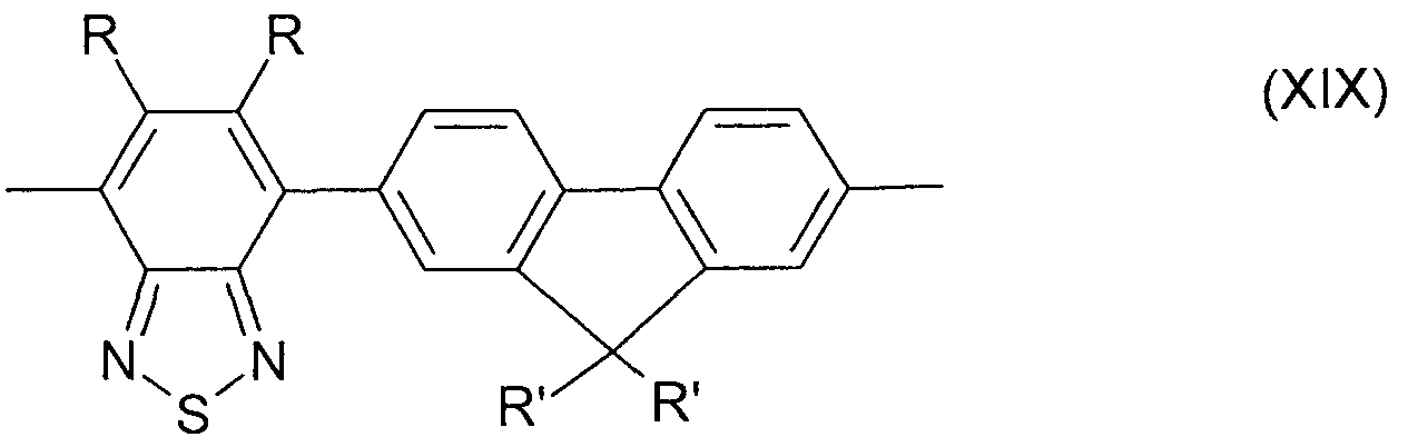


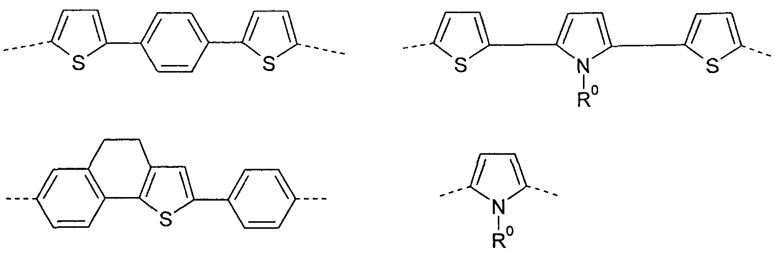


Claims


Priority Applications (5)
| Application Number | Priority Date | Filing Date | Title |
|---|---|---|---|
| JP2016530362A JP2016525781A (en) | 2013-07-29 | 2014-06-26 | Electro-optic element and use thereof |
| EP14733092.2A EP3028318A1 (en) | 2013-07-29 | 2014-06-26 | Electro-optical device and the use thereof |
| CN201480042708.1A CN105409022B (en) | 2013-07-29 | 2014-06-26 | Electro-optical device and application thereof |
| KR1020167005194A KR102238849B1 (en) | 2013-07-29 | 2014-06-26 | Electro-optical device and the use thereof |
| US14/908,335 US20160163987A1 (en) | 2013-07-29 | 2014-06-26 | Electro-optical device and the use thereof |
Applications Claiming Priority (2)
| Application Number | Priority Date | Filing Date | Title |
|---|---|---|---|
| EP13003770 | 2013-07-29 | ||
| EP13003770.8 | 2013-07-29 |
Publications (1)
| Publication Number | Publication Date |
|---|---|
| WO2015014427A1 true WO2015014427A1 (en) | 2015-02-05 |
Family
ID=48915802
Family Applications (1)
| Application Number | Title | Priority Date | Filing Date |
|---|---|---|---|
| PCT/EP2014/001738 WO2015014427A1 (en) | 2013-07-29 | 2014-06-26 | Electro-optical device and the use thereof |
Country Status (6)
| Country | Link |
|---|---|
| US (1) | US20160163987A1 (en) |
| EP (1) | EP3028318A1 (en) |
| JP (2) | JP2016525781A (en) |
| KR (1) | KR102238849B1 (en) |
| CN (1) | CN105409022B (en) |
| WO (1) | WO2015014427A1 (en) |
Cited By (1)
| Publication number | Priority date | Publication date | Assignee | Title |
|---|---|---|---|---|
| WO2017061332A1 (en) * | 2015-10-06 | 2017-04-13 | 住友化学株式会社 | Light-emitting element |
Families Citing this family (1)
| Publication number | Priority date | Publication date | Assignee | Title |
|---|---|---|---|---|
| WO2017195559A1 (en) * | 2016-05-10 | 2017-11-16 | 日立化成株式会社 | Charge transport material, organic electronic element and organic electroluminescent element |
Citations (151)
| Publication number | Priority date | Publication date | Assignee | Title |
|---|---|---|---|---|
| US3180730A (en) | 1959-04-09 | 1965-04-27 | Azoplate Corp | Material for electrophotographic purposes |
| US3526501A (en) | 1967-02-03 | 1970-09-01 | Eastman Kodak Co | 4-diarylamino-substituted chalcone containing photoconductive compositions for use in electrophotography |
| US3567450A (en) | 1968-02-20 | 1971-03-02 | Eastman Kodak Co | Photoconductive elements containing substituted triarylamine photoconductors |
| US3615404A (en) | 1968-04-25 | 1971-10-26 | Scott Paper Co | 1 3-phenylenediamine containing photoconductive materials |
| US3615402A (en) | 1969-10-01 | 1971-10-26 | Eastman Kodak Co | Tetra-substituted methanes as organic photoconductors |
| US3717462A (en) | 1969-07-28 | 1973-02-20 | Canon Kk | Heat treatment of an electrophotographic photosensitive member |
| US4127412A (en) | 1975-12-09 | 1978-11-28 | Eastman Kodak Company | Photoconductive compositions and elements |
| JPS54110837A (en) | 1978-02-17 | 1979-08-30 | Ricoh Co Ltd | Electrophotographic photoreceptor |
| JPS5646234A (en) | 1979-09-21 | 1981-04-27 | Ricoh Co Ltd | Electrophotographic receptor |
| US4356429A (en) | 1980-07-17 | 1982-10-26 | Eastman Kodak Company | Organic electroluminescent cell |
| US4539507A (en) | 1983-03-25 | 1985-09-03 | Eastman Kodak Company | Organic electroluminescent devices having improved power conversion efficiencies |
| JPS61210363A (en) | 1985-03-15 | 1986-09-18 | Canon Inc | Electrophotographic sensitive body |
| US4720432A (en) | 1987-02-11 | 1988-01-19 | Eastman Kodak Company | Electroluminescent device with organic luminescent medium |
| US4769292A (en) | 1987-03-02 | 1988-09-06 | Eastman Kodak Company | Electroluminescent device with modified thin film luminescent zone |
| JPS63256965A (en) | 1987-04-15 | 1988-10-24 | Canon Inc | Toner for developing electrostatic charge image |
| JPH02204996A (en) | 1989-02-01 | 1990-08-14 | Nec Corp | Organic film type el element |
| US4950950A (en) | 1989-05-18 | 1990-08-21 | Eastman Kodak Company | Electroluminescent device with silazane-containing luminescent zone |
| JPH02282263A (en) | 1988-12-09 | 1990-11-19 | Nippon Oil Co Ltd | Hole transferring material |
| US5061569A (en) | 1990-07-26 | 1991-10-29 | Eastman Kodak Company | Electroluminescent device with organic electroluminescent medium |
| US5121029A (en) | 1987-12-11 | 1992-06-09 | Idemitsu Kosan Co., Ltd. | Electroluminescence device having an organic electroluminescent element |
| US5130603A (en) | 1989-03-20 | 1992-07-14 | Idemitsu Kosan Co., Ltd. | Organic electroluminescence device |
| JPH04308688A (en) | 1991-04-08 | 1992-10-30 | Pioneer Electron Corp | Organic electroluminescence element |
| EP0650955A1 (en) | 1993-11-01 | 1995-05-03 | Hodogaya Chemical Co., Ltd. | Amine compound and electro-luminescence device comprising same |
| EP0676461A2 (en) | 1994-04-07 | 1995-10-11 | Hoechst Aktiengesellschaft | Spiro compounds and their application as electroluminescence materials |
| JPH0853397A (en) | 1994-08-12 | 1996-02-27 | Toyo Ink Mfg Co Ltd | Diarylamine derivative, its production and use thereof |
| US5529853A (en) | 1993-03-17 | 1996-06-25 | Sanyo Electric Co., Ltd. | Organic electroluminescent element |
| WO1998004007A1 (en) | 1996-07-17 | 1998-01-29 | Robert Bosch Gmbh | Electron-conducting layer in organic, electroluminescent arrangements |
| DE19646119A1 (en) | 1996-11-08 | 1998-05-14 | Hoechst Ag | Electroluminescent device |
| US5766779A (en) | 1996-08-20 | 1998-06-16 | Eastman Kodak Company | Electron transporting materials for organic electroluminescent devices |
| JP2913116B2 (en) | 1990-11-20 | 1999-06-28 | 株式会社リコー | EL device |
| US5962631A (en) | 1995-07-28 | 1999-10-05 | The Dow Chemical Company | 2, 7-aryl-9-substituted fluorenes and 9-substituted fluorene oligomers and polymers |
| US6020078A (en) | 1998-12-18 | 2000-02-01 | Eastman Kodak Company | Green organic electroluminescent devices |
| EP1009041A2 (en) | 1998-12-09 | 2000-06-14 | Eastman Kodak Company | Electroluminescent device with improved hole transport layer |
| WO2000046321A1 (en) | 1999-02-04 | 2000-08-10 | The Dow Chemical Company | Fluorene copolymers and devices made therefrom |
| WO2000070655A2 (en) | 1999-05-13 | 2000-11-23 | The Trustees Of Princeton University | Very high efficiency organic light emitting devices based on electrophosphorescence |
| WO2001021729A1 (en) | 1999-09-21 | 2001-03-29 | Idemitsu Kosan Co., Ltd. | Organic electroluminescence and organic luminous medium |
| US6225467B1 (en) | 2000-01-21 | 2001-05-01 | Xerox Corporation | Electroluminescent (EL) devices |
| US6229012B1 (en) | 1998-10-01 | 2001-05-08 | Xerox Corporation | Triazine compositions |
| WO2001041512A1 (en) | 1999-12-01 | 2001-06-07 | The Trustees Of Princeton University | Complexes of form l2mx as phosphorescent dopants for organic leds |
| US6251531B1 (en) | 1995-02-25 | 2001-06-26 | Toyo Ink Manufacturing Co., Ltd. | Light-emitting material for organic electroluminescence device, and organic electroluminescence device for which the light-emitting material is adapted |
| JP2001267080A (en) | 2000-01-14 | 2001-09-28 | Toray Ind Inc | Light emission element |
| EP1162193A1 (en) | 1993-09-29 | 2001-12-12 | Idemitsu Kosan Company Limited | Acrylenediamine derivatives and organic electroluminescence device containing the same |
| US20010053462A1 (en) | 2000-05-02 | 2001-12-20 | Masayuki Mishima | Light-emitting device |
| WO2002002714A2 (en) | 2000-06-30 | 2002-01-10 | E.I. Du Pont De Nemours And Company | Electroluminescent iridium compounds with fluorinated phenylpyridines, phenylpyrimidines, and phenylquinolines and devices made with such compounds |
| WO2002015645A1 (en) | 2000-08-11 | 2002-02-21 | The Trustees Of Princeton University | Organometallic compounds and emission-shifting organic electrophosphorescence |
| EP1191614A2 (en) | 2000-09-26 | 2002-03-27 | Canon Kabushiki Kaisha | Luminescence device and metal coordination compound therefor |
| EP1191613A2 (en) | 2000-09-26 | 2002-03-27 | Canon Kabushiki Kaisha | Luminescence device, display apparatus and metal coordination compound |
| EP1191612A2 (en) | 2000-09-26 | 2002-03-27 | Canon Kabushiki Kaisha | Luminescence device, display apparatus and metal coordination compound |
| EP1205527A1 (en) | 2000-03-27 | 2002-05-15 | Idemitsu Kosan Co., Ltd. | Organic electroluminescence device |
| WO2002043449A1 (en) | 2000-11-24 | 2002-05-30 | Toray Industries, Inc. | Luminescent element material and luminescent element comprising the same |
| WO2003020790A2 (en) | 2001-09-04 | 2003-03-13 | Covion Organic Semiconductors Gmbh | Conjugated polymers containing spirobifluorene units and the use thereof |
| JP2003115387A (en) | 2001-10-04 | 2003-04-18 | Junji Kido | Organic light emitting element and its manufacturing method |
| WO2003048225A2 (en) | 2001-12-06 | 2003-06-12 | Covion Organic Semiconductors Gmbh | Process for producing aryl-aryl coupled compounds |
| JP2003253145A (en) | 2002-02-28 | 2003-09-10 | Jsr Corp | Light-emitting composition |
| US20030170490A1 (en) | 2002-01-29 | 2003-09-11 | Xerox Corporation | Organic electroluminescent (EL) devices |
| EP1344788A1 (en) | 2002-03-15 | 2003-09-17 | Sumitomo Chemical Company, Limited | Conjugated polymer comprising dibenzothiophene- or dibenzofuran-units and their use in polymer LEDs |
| DE10312675A1 (en) | 2002-03-25 | 2003-10-09 | Dainippon Printing Co Ltd | New 2,4,6-tricarbazolyl-1,3,5-triazine derivatives useful as dyes for coloring high molecular weight organic materials and in organic electroluminescent devices |
| JP2003338375A (en) | 2002-03-14 | 2003-11-28 | Tdk Corp | Organic el element |
| WO2003099901A1 (en) | 2002-05-28 | 2003-12-04 | Sumitomo Chemical Company, Limited | Polymer and polymeric luminescent element comprising the same |
| WO2004013080A1 (en) | 2002-08-01 | 2004-02-12 | Covion Organic Semiconductors Gmbh | Spirobifluorene derivatives, their preparation and uses thereof |
| WO2004037887A2 (en) | 2002-10-25 | 2004-05-06 | Covion Organic Semiconductors Gmbh | Conjugated polymers containing arylamine units, the representation thereof and the use of the same |
| WO2004041901A1 (en) | 2002-11-08 | 2004-05-21 | Covion Organic Semiconductors Gmbh | Aryl-substituted polyindenofluorenes for use in organic electroluminiscent devices |
| EP1138746B1 (en) | 2000-03-31 | 2004-05-26 | Sumitomo Chemical Company, Limited | Polymeric fluorescent substance, production method therof, and polymer light-emitting device using the same |
| JP2004200162A (en) | 2002-12-05 | 2004-07-15 | Toray Ind Inc | Light emitting element |
| WO2004058911A2 (en) | 2002-12-23 | 2004-07-15 | Covion Organic Semiconductors Gmbh | Organic electroluminescent element |
| EP1444008A2 (en) | 2001-11-17 | 2004-08-11 | The University Court of the University of St Andrews | Therapeutic light-emitting device |
| WO2004081017A1 (en) | 2003-03-11 | 2004-09-23 | Covion Organic Semiconductors Gmbh | Metal complexes |
| WO2004084260A2 (en) | 2003-03-20 | 2004-09-30 | Cambridge Display Technology Limited | Electroluminescent device |
| JP2004288381A (en) | 2003-03-19 | 2004-10-14 | Konica Minolta Holdings Inc | Organic electroluminescent element |
| EP1469533A2 (en) | 2003-04-14 | 2004-10-20 | Kabushiki Kaisha Toyota Jidoshokki | Organic electroluminescent element that supresses generation of ultraviolet light and lighting system that has organic electroluminescent element |
| WO2004093207A2 (en) | 2003-04-15 | 2004-10-28 | Covion Organic Semiconductors Gmbh | Mixtures of matrix materials and organic semiconductors capable of emission, use of the same and electronic components containing said mixtures |
| JP2004311184A (en) | 2003-04-04 | 2004-11-04 | Junji Kido | Electron transportation material formed of multinucleate phenanthroline derivative, charge control material, and organic luminescent element using them |
| EP1478032A2 (en) | 2003-05-16 | 2004-11-17 | Kabushiki Kaisha Toyota Jidoshokki | Light emitting diode method for forming the same |
| EP1480280A2 (en) | 2003-05-23 | 2004-11-24 | Kabushiki Kaisha Toyota Jidoshokki | Organic electroluminescent device and method for manufacturing the same |
| US6824895B1 (en) | 2003-12-05 | 2004-11-30 | Eastman Kodak Company | Electroluminescent device containing organometallic compound with tridentate ligand |
| US6830828B2 (en) | 1998-09-14 | 2004-12-14 | The Trustees Of Princeton University | Organometallic complexes as phosphorescent emitters in organic LEDs |
| US6835469B2 (en) | 2001-10-17 | 2004-12-28 | The University Of Southern California | Phosphorescent compounds and devices comprising the same |
| WO2004113412A2 (en) | 2003-06-23 | 2004-12-29 | Covion Organic Semiconductors Gmbh | Polymer |
| WO2005003253A2 (en) | 2003-07-07 | 2005-01-13 | Covion Organic Semiconductors Gmbh | Mixtures of organic emissive semiconductors and matrix materials, their use and electronic components comprising said materials |
| WO2005014689A2 (en) | 2003-08-12 | 2005-02-17 | Covion Organic Semiconductors Gmbh | Conjugated polymers containing dihydrophenanthrene units and use thereof |
| CN1583691A (en) | 2004-06-04 | 2005-02-23 | 友达光电股份有限公司 | Anthracene compound and organic electroluminescent apparatus containing it |
| US20050069729A1 (en) | 2003-09-30 | 2005-03-31 | Konica Minolta Holdings, Inc. | Organic electroluminescent element, illuminator, display and compound |
| WO2005030827A1 (en) | 2003-09-20 | 2005-04-07 | Covion Organic Semiconductors Gmbh | White-emitting copolymers, representation and use thereof |
| US6878469B2 (en) | 2002-01-18 | 2005-04-12 | Lg Chem, Ltd. | Material for transporting electrons and organic electroluminescent display using the same |
| WO2005033174A1 (en) | 2003-10-01 | 2005-04-14 | Sumitomo Chemical Company, Limited | Polymer light-emitting material and polymer light-emitting device |
| WO2005033244A1 (en) | 2003-09-29 | 2005-04-14 | Covion Organic Semiconductors Gmbh | Metal complexes |
| JP2005108556A (en) | 2003-09-29 | 2005-04-21 | Tdk Corp | Organic el element and organic el display |
| GB2408092A (en) | 2003-11-13 | 2005-05-18 | Ahad Ramezanpour | A heat exchanger |
| WO2005056633A1 (en) | 2003-12-12 | 2005-06-23 | Sumitomo Chemical Company, Limited | Polymer compound and polymer light-emitting device using same |
| EP1551206A1 (en) | 2002-10-09 | 2005-07-06 | Idemitsu Kosan Co., Ltd. | Organic electroluminescent device |
| WO2005084081A1 (en) | 2004-02-20 | 2005-09-09 | Merck Patent Gmbh | Organic electronic devices |
| JP2005285661A (en) | 2004-03-30 | 2005-10-13 | Tdk Corp | Organic el element and organic el display |
| WO2005104264A1 (en) | 2004-04-26 | 2005-11-03 | Merck Patent Gmbh | Electroluminescent polymers and use therof |
| WO2005111172A2 (en) | 2004-05-11 | 2005-11-24 | Merck Patent Gmbh | Novel material mixtures for use in electroluminescence |
| JP2005347160A (en) | 2004-06-04 | 2005-12-15 | Konica Minolta Holdings Inc | Organic electroluminescent element, lighting device, and display device |
| WO2006000388A1 (en) | 2004-06-26 | 2006-01-05 | Merck Patent Gmbh | Organic electroluminescent device |
| WO2006000389A1 (en) | 2004-06-26 | 2006-01-05 | Merck Patent Gmbh | Compounds for organic electronic devices |
| EP1617710A1 (en) | 2003-04-23 | 2006-01-18 | Konica Minolta Holdings, Inc. | Material for organic electroluminescent device, organic electroluminescent device, illuminating device and display |
| DE102004032527A1 (en) | 2004-07-06 | 2006-02-02 | Covion Organic Semiconductors Gmbh | Electroluminescent polymers |
| US7029766B2 (en) | 2003-12-05 | 2006-04-18 | Eastman Kodak Company | Organic element for electroluminescent devices |
| WO2006048268A1 (en) | 2004-11-06 | 2006-05-11 | Merck Patent Gmbh | Organic electroluminescent device |
| WO2006052457A2 (en) | 2004-11-03 | 2006-05-18 | Sumation Co.Ltd. | New class of bridged biphenylene polymers |
| WO2006058737A1 (en) | 2004-12-01 | 2006-06-08 | Merck Patent Gmbh | Compounds for organic electronic devices |
| WO2006063852A1 (en) | 2004-12-18 | 2006-06-22 | Merck Patent Gmbh | Electroluminescent polymers and use thereof |
| US20060147747A1 (en) | 2003-03-13 | 2006-07-06 | Hiroshi Yamamoto | Nitrogen-containing heterocycle derivative and organic electroluminescent element using the same |
| US20060210830A1 (en) | 2005-03-15 | 2006-09-21 | Idemitsu Kosan Co., Ltd. | Aromatic amine derivative and organic electroluminescence device using the same |
| US20060222886A1 (en) | 2005-04-04 | 2006-10-05 | Raymond Kwong | Arylpyrene compounds |
| WO2006118345A1 (en) | 2005-04-28 | 2006-11-09 | Sumitomo Chemical Company, Limited | High-molecular compounds and high-molecular luminescent devices made by using the same |
| WO2006117052A1 (en) | 2005-05-03 | 2006-11-09 | Merck Patent Gmbh | Organic electroluminescent device and boric acid and borinic acid derivatives used therein |
| WO2006122630A1 (en) | 2005-05-20 | 2006-11-23 | Merck Patent Gmbh | Compounds for organic electronic devices |
| EP1731584A1 (en) | 2004-03-31 | 2006-12-13 | Konica Minolta Holdings, Inc. | Organic electroluminescent device material, organic electroluminescent device, display and illuminating device |
| JP2007059939A (en) | 2001-08-31 | 2007-03-08 | Nippon Hoso Kyokai <Nhk> | Organic light emitting device and display unit |
| US20070087219A1 (en) | 2005-10-19 | 2007-04-19 | Eastman Kodak Company | Electroluminescent device |
| WO2007043495A1 (en) | 2005-10-07 | 2007-04-19 | Sumitomo Chemical Company, Limited | Copolymer and polymer light emitting devices made by using the same |
| US20070092753A1 (en) | 2005-10-26 | 2007-04-26 | Eastman Kodak Company | Organic element for low voltage electroluminescent devices |
| US20070092755A1 (en) | 2005-10-26 | 2007-04-26 | Eastman Kodak Company | Organic element for low voltage electroluminescent devices |
| US20070104977A1 (en) | 2005-11-07 | 2007-05-10 | Idemitsu Kosan Co., Ltd. | Organic electroluminescent device |
| US20070122656A1 (en) | 2005-11-30 | 2007-05-31 | Eastman Kodak Company | Electroluminescent device containing an anthracene derivative |
| WO2007065549A1 (en) | 2005-12-08 | 2007-06-14 | Merck Patent Gmbh | Organic electroluminescent devices |
| US20070134514A1 (en) | 2005-12-14 | 2007-06-14 | Eastman Kodak Company | Electroluminescent host material |
| DE102005058557A1 (en) | 2005-12-08 | 2007-06-14 | Merck Patent Gmbh | Organic electroluminescent device |
| DE102005060473A1 (en) | 2005-12-17 | 2007-06-28 | Merck Patent Gmbh | Conjugated polymers, their preparation and use |
| US7250532B2 (en) | 2001-03-16 | 2007-07-31 | Idemitsu Kosan Co., Ltd. | Method for producing aromatic amino compound |
| US7250226B2 (en) | 2001-08-31 | 2007-07-31 | Nippon Hoso Kyokai | Phosphorescent compound, a phosphorescent composition and an organic light-emitting device |
| DE102006003710A1 (en) | 2006-01-26 | 2007-08-02 | Merck Patent Gmbh | New polymer containing an unit exhibiting electron injection and -conducting characteristics, useful for the preparation of a solution and formulation, and in an organic electronic devices, preferably organic optoelectronic device |
| JP2007197574A (en) | 2006-01-26 | 2007-08-09 | Showa Denko Kk | Polymeric luminescent material, organic electroluminescence element and display device |
| JP2007211243A (en) | 2007-02-07 | 2007-08-23 | Showa Denko Kk | Polymer of polymerizable compound |
| WO2007095118A2 (en) | 2006-02-10 | 2007-08-23 | Universal Display Corporation | METAL COMPLEXES OF CYCLOMETALLATED IMIDAZO[1,2-f]PHENANTHRIDINE AND DIIMIDAZO[1,2-A:1',2'-C]QUINAZOLINE LIGANDS AND ISOELECTRONIC AND BENZANNULATED ANALOGS THEREOF |
| EP1834945A1 (en) | 2005-01-05 | 2007-09-19 | Idemitsu Kosan Co., Ltd. | Aromatic amine derivative and organic electroluminescent device using same |
| WO2007115610A1 (en) | 2006-04-01 | 2007-10-18 | Merck Patent Gmbh | Materials for organic electroluminescent devices |
| US20070252517A1 (en) | 2006-04-27 | 2007-11-01 | Eastman Kodak Company | Electroluminescent device including an anthracene derivative |
| EP1860097A1 (en) | 2005-03-18 | 2007-11-28 | Idemitsu Kosan Co., Ltd. | Aromatic amine derivative and organic electroluminescence device utilizing the same |
| US20070273272A1 (en) | 2006-04-03 | 2007-11-29 | Idemitsu Kosan Co., Ltd. | Benzanthracene derivative and electroluminescence device using the same |
| WO2007137725A1 (en) | 2006-05-31 | 2007-12-06 | Merck Patent Gmbh | New materials for organic electroluminescent devices |
| WO2007140847A1 (en) | 2006-06-02 | 2007-12-13 | Merck Patent Gmbh | Materials for organic electroluminescent devices |
| WO2008006449A1 (en) | 2006-07-11 | 2008-01-17 | Merck Patent Gmbh | Novel materials for organic electroluminescent devices |
| US20080113101A1 (en) | 2006-11-09 | 2008-05-15 | Idemitsu Kosan Co., Ltd. | Organic-electroluminescence-material-containing solution, method for forming thin film of organic electroluminescence material, thin film of organic electroluminescence material and organic electroluminescence device |
| US7378162B2 (en) | 2005-03-08 | 2008-05-27 | Lg Electronics Inc. | Organic electroluminescence devices using red phosphorescence compounds |
| DE102007002714A1 (en) | 2007-01-18 | 2008-07-31 | Merck Patent Gmbh | New materials for organic electroluminescent devices |
| US20080193796A1 (en) | 2006-11-20 | 2008-08-14 | Idemitsu Kosan Co., Ltd. | Organic electroluminescent device |
| EP1984964A1 (en) * | 2006-02-13 | 2008-10-29 | Merck Patent GmbH | Electronic component, method for its production and its use |
| DE102007024850A1 (en) | 2007-05-29 | 2008-12-04 | Merck Patent Gmbh | New materials for organic electroluminescent devices |
| US20090061681A1 (en) | 2007-09-05 | 2009-03-05 | Mcmunigal Tom | Electrical receptacle assembly |
| WO2009041635A1 (en) | 2007-09-28 | 2009-04-02 | Idemitsu Kosan Co., Ltd. | Organic el device |
| DE102008017591A1 (en) | 2008-04-07 | 2009-10-08 | Merck Patent Gmbh | New materials for organic electroluminescent devices |
| WO2010022847A1 (en) | 2008-08-29 | 2010-03-04 | Merck Patent Gmbh | Electroluminescent polymers, method for the production thereof, and use thereof |
| WO2010136110A2 (en) | 2009-05-29 | 2010-12-02 | Merck Patent Gmbh | Polymers comprising substituted indenofluorene derivates as structural units, method for the production thereof, and use thereof |
| WO2010136111A1 (en) | 2009-05-29 | 2010-12-02 | Merck Patent Gmbh | Composition, containing at least one emitter compound and at least one polymer with conjugation-interrupting units |
| WO2010149261A1 (en) | 2009-06-26 | 2010-12-29 | Merck Patent Gmbh | Polymers containing structural units that comprise alkyl alkoxy groups, blends containing said polymers, and optoelectronic devices containing said polymers and blends |
| WO2012171609A1 (en) | 2011-06-17 | 2012-12-20 | Merck Patent Gmbh | Materials for organic electroluminescent devices |
| WO2013021180A1 (en) * | 2011-08-05 | 2013-02-14 | Cambridge Display Technology Limited | Light emitting polymers and devices |
Family Cites Families (7)
| Publication number | Priority date | Publication date | Assignee | Title |
|---|---|---|---|---|
| GB9805476D0 (en) * | 1998-03-13 | 1998-05-13 | Cambridge Display Tech Ltd | Electroluminescent devices |
| GB0422391D0 (en) * | 2004-10-08 | 2004-11-10 | Cambridge Display Tech Ltd | Light emitting device |
| ATE555506T1 (en) * | 2004-12-24 | 2012-05-15 | Cdt Oxford Ltd | LIGHT EMITTING DEVICE |
| US9200156B2 (en) * | 2006-07-25 | 2015-12-01 | Merck Patent Gmbh | Polymer blends and their use in organic light emitting devices |
| US9105847B2 (en) * | 2010-06-24 | 2015-08-11 | Joled Inc. | Organic EL display and method of manufacturing the same |
| DE102010056151A1 (en) * | 2010-12-28 | 2012-06-28 | Merck Patent Gmbh | Materials for organic electroluminescent devices |
| KR101921896B1 (en) * | 2011-12-12 | 2018-11-26 | 메르크 파텐트 게엠베하 | Compounds for electronic devices |
-
2014
- 2014-06-26 CN CN201480042708.1A patent/CN105409022B/en active Active
- 2014-06-26 KR KR1020167005194A patent/KR102238849B1/en active IP Right Grant
- 2014-06-26 JP JP2016530362A patent/JP2016525781A/en active Pending
- 2014-06-26 US US14/908,335 patent/US20160163987A1/en not_active Abandoned
- 2014-06-26 EP EP14733092.2A patent/EP3028318A1/en not_active Ceased
- 2014-06-26 WO PCT/EP2014/001738 patent/WO2015014427A1/en active Application Filing
-
2019
- 2019-11-20 JP JP2019209650A patent/JP6848033B2/en active Active
Patent Citations (156)
| Publication number | Priority date | Publication date | Assignee | Title |
|---|---|---|---|---|
| US3180730A (en) | 1959-04-09 | 1965-04-27 | Azoplate Corp | Material for electrophotographic purposes |
| US3526501A (en) | 1967-02-03 | 1970-09-01 | Eastman Kodak Co | 4-diarylamino-substituted chalcone containing photoconductive compositions for use in electrophotography |
| US3567450A (en) | 1968-02-20 | 1971-03-02 | Eastman Kodak Co | Photoconductive elements containing substituted triarylamine photoconductors |
| US3615404A (en) | 1968-04-25 | 1971-10-26 | Scott Paper Co | 1 3-phenylenediamine containing photoconductive materials |
| US3717462A (en) | 1969-07-28 | 1973-02-20 | Canon Kk | Heat treatment of an electrophotographic photosensitive member |
| US3615402A (en) | 1969-10-01 | 1971-10-26 | Eastman Kodak Co | Tetra-substituted methanes as organic photoconductors |
| US4127412A (en) | 1975-12-09 | 1978-11-28 | Eastman Kodak Company | Photoconductive compositions and elements |
| JPS54110837A (en) | 1978-02-17 | 1979-08-30 | Ricoh Co Ltd | Electrophotographic photoreceptor |
| JPS5646234A (en) | 1979-09-21 | 1981-04-27 | Ricoh Co Ltd | Electrophotographic receptor |
| US4356429A (en) | 1980-07-17 | 1982-10-26 | Eastman Kodak Company | Organic electroluminescent cell |
| US4539507A (en) | 1983-03-25 | 1985-09-03 | Eastman Kodak Company | Organic electroluminescent devices having improved power conversion efficiencies |
| JPS61210363A (en) | 1985-03-15 | 1986-09-18 | Canon Inc | Electrophotographic sensitive body |
| US4720432A (en) | 1987-02-11 | 1988-01-19 | Eastman Kodak Company | Electroluminescent device with organic luminescent medium |
| US4769292A (en) | 1987-03-02 | 1988-09-06 | Eastman Kodak Company | Electroluminescent device with modified thin film luminescent zone |
| JPS63256965A (en) | 1987-04-15 | 1988-10-24 | Canon Inc | Toner for developing electrostatic charge image |
| US5121029A (en) | 1987-12-11 | 1992-06-09 | Idemitsu Kosan Co., Ltd. | Electroluminescence device having an organic electroluminescent element |
| JPH02282263A (en) | 1988-12-09 | 1990-11-19 | Nippon Oil Co Ltd | Hole transferring material |
| JPH02204996A (en) | 1989-02-01 | 1990-08-14 | Nec Corp | Organic film type el element |
| US5130603A (en) | 1989-03-20 | 1992-07-14 | Idemitsu Kosan Co., Ltd. | Organic electroluminescence device |
| US4950950A (en) | 1989-05-18 | 1990-08-21 | Eastman Kodak Company | Electroluminescent device with silazane-containing luminescent zone |
| US5061569A (en) | 1990-07-26 | 1991-10-29 | Eastman Kodak Company | Electroluminescent device with organic electroluminescent medium |
| JP2913116B2 (en) | 1990-11-20 | 1999-06-28 | 株式会社リコー | EL device |
| JPH04308688A (en) | 1991-04-08 | 1992-10-30 | Pioneer Electron Corp | Organic electroluminescence element |
| US5529853A (en) | 1993-03-17 | 1996-06-25 | Sanyo Electric Co., Ltd. | Organic electroluminescent element |
| EP1162193A1 (en) | 1993-09-29 | 2001-12-12 | Idemitsu Kosan Company Limited | Acrylenediamine derivatives and organic electroluminescence device containing the same |
| EP0650955A1 (en) | 1993-11-01 | 1995-05-03 | Hodogaya Chemical Co., Ltd. | Amine compound and electro-luminescence device comprising same |
| EP0676461A2 (en) | 1994-04-07 | 1995-10-11 | Hoechst Aktiengesellschaft | Spiro compounds and their application as electroluminescence materials |
| JPH0853397A (en) | 1994-08-12 | 1996-02-27 | Toyo Ink Mfg Co Ltd | Diarylamine derivative, its production and use thereof |
| US6251531B1 (en) | 1995-02-25 | 2001-06-26 | Toyo Ink Manufacturing Co., Ltd. | Light-emitting material for organic electroluminescence device, and organic electroluminescence device for which the light-emitting material is adapted |
| US5962631A (en) | 1995-07-28 | 1999-10-05 | The Dow Chemical Company | 2, 7-aryl-9-substituted fluorenes and 9-substituted fluorene oligomers and polymers |
| WO1998004007A1 (en) | 1996-07-17 | 1998-01-29 | Robert Bosch Gmbh | Electron-conducting layer in organic, electroluminescent arrangements |
| US6352791B1 (en) | 1996-07-17 | 2002-03-05 | Robert Bosch Gmbh | Electron-conducting layer in organic electroluminescent arrangements |
| US5766779A (en) | 1996-08-20 | 1998-06-16 | Eastman Kodak Company | Electron transporting materials for organic electroluminescent devices |
| DE19646119A1 (en) | 1996-11-08 | 1998-05-14 | Hoechst Ag | Electroluminescent device |
| US6830828B2 (en) | 1998-09-14 | 2004-12-14 | The Trustees Of Princeton University | Organometallic complexes as phosphorescent emitters in organic LEDs |
| US6229012B1 (en) | 1998-10-01 | 2001-05-08 | Xerox Corporation | Triazine compositions |
| EP1009041A2 (en) | 1998-12-09 | 2000-06-14 | Eastman Kodak Company | Electroluminescent device with improved hole transport layer |
| US6020078A (en) | 1998-12-18 | 2000-02-01 | Eastman Kodak Company | Green organic electroluminescent devices |
| WO2000046321A1 (en) | 1999-02-04 | 2000-08-10 | The Dow Chemical Company | Fluorene copolymers and devices made therefrom |
| WO2000070655A2 (en) | 1999-05-13 | 2000-11-23 | The Trustees Of Princeton University | Very high efficiency organic light emitting devices based on electrophosphorescence |
| WO2001021729A1 (en) | 1999-09-21 | 2001-03-29 | Idemitsu Kosan Co., Ltd. | Organic electroluminescence and organic luminous medium |
| WO2001041512A1 (en) | 1999-12-01 | 2001-06-07 | The Trustees Of Princeton University | Complexes of form l2mx as phosphorescent dopants for organic leds |
| JP2001267080A (en) | 2000-01-14 | 2001-09-28 | Toray Ind Inc | Light emission element |
| US6225467B1 (en) | 2000-01-21 | 2001-05-01 | Xerox Corporation | Electroluminescent (EL) devices |
| EP1205527A1 (en) | 2000-03-27 | 2002-05-15 | Idemitsu Kosan Co., Ltd. | Organic electroluminescence device |
| EP1138746B1 (en) | 2000-03-31 | 2004-05-26 | Sumitomo Chemical Company, Limited | Polymeric fluorescent substance, production method therof, and polymer light-emitting device using the same |
| US20010053462A1 (en) | 2000-05-02 | 2001-12-20 | Masayuki Mishima | Light-emitting device |
| WO2002002714A2 (en) | 2000-06-30 | 2002-01-10 | E.I. Du Pont De Nemours And Company | Electroluminescent iridium compounds with fluorinated phenylpyridines, phenylpyrimidines, and phenylquinolines and devices made with such compounds |
| WO2002015645A1 (en) | 2000-08-11 | 2002-02-21 | The Trustees Of Princeton University | Organometallic compounds and emission-shifting organic electrophosphorescence |
| EP1191612A2 (en) | 2000-09-26 | 2002-03-27 | Canon Kabushiki Kaisha | Luminescence device, display apparatus and metal coordination compound |
| EP1191614A2 (en) | 2000-09-26 | 2002-03-27 | Canon Kabushiki Kaisha | Luminescence device and metal coordination compound therefor |
| EP1191613A2 (en) | 2000-09-26 | 2002-03-27 | Canon Kabushiki Kaisha | Luminescence device, display apparatus and metal coordination compound |
| WO2002043449A1 (en) | 2000-11-24 | 2002-05-30 | Toray Industries, Inc. | Luminescent element material and luminescent element comprising the same |
| US7250532B2 (en) | 2001-03-16 | 2007-07-31 | Idemitsu Kosan Co., Ltd. | Method for producing aromatic amino compound |
| US7250226B2 (en) | 2001-08-31 | 2007-07-31 | Nippon Hoso Kyokai | Phosphorescent compound, a phosphorescent composition and an organic light-emitting device |
| JP2007059939A (en) | 2001-08-31 | 2007-03-08 | Nippon Hoso Kyokai <Nhk> | Organic light emitting device and display unit |
| WO2003020790A2 (en) | 2001-09-04 | 2003-03-13 | Covion Organic Semiconductors Gmbh | Conjugated polymers containing spirobifluorene units and the use thereof |
| JP2003115387A (en) | 2001-10-04 | 2003-04-18 | Junji Kido | Organic light emitting element and its manufacturing method |
| US6835469B2 (en) | 2001-10-17 | 2004-12-28 | The University Of Southern California | Phosphorescent compounds and devices comprising the same |
| EP1444008A2 (en) | 2001-11-17 | 2004-08-11 | The University Court of the University of St Andrews | Therapeutic light-emitting device |
| WO2003048225A2 (en) | 2001-12-06 | 2003-06-12 | Covion Organic Semiconductors Gmbh | Process for producing aryl-aryl coupled compounds |
| US6878469B2 (en) | 2002-01-18 | 2005-04-12 | Lg Chem, Ltd. | Material for transporting electrons and organic electroluminescent display using the same |
| US20030170490A1 (en) | 2002-01-29 | 2003-09-11 | Xerox Corporation | Organic electroluminescent (EL) devices |
| JP2003253145A (en) | 2002-02-28 | 2003-09-10 | Jsr Corp | Light-emitting composition |
| JP2003338375A (en) | 2002-03-14 | 2003-11-28 | Tdk Corp | Organic el element |
| EP1344788A1 (en) | 2002-03-15 | 2003-09-17 | Sumitomo Chemical Company, Limited | Conjugated polymer comprising dibenzothiophene- or dibenzofuran-units and their use in polymer LEDs |
| DE10312675A1 (en) | 2002-03-25 | 2003-10-09 | Dainippon Printing Co Ltd | New 2,4,6-tricarbazolyl-1,3,5-triazine derivatives useful as dyes for coloring high molecular weight organic materials and in organic electroluminescent devices |
| WO2003099901A1 (en) | 2002-05-28 | 2003-12-04 | Sumitomo Chemical Company, Limited | Polymer and polymeric luminescent element comprising the same |
| WO2004013080A1 (en) | 2002-08-01 | 2004-02-12 | Covion Organic Semiconductors Gmbh | Spirobifluorene derivatives, their preparation and uses thereof |
| EP1551206A1 (en) | 2002-10-09 | 2005-07-06 | Idemitsu Kosan Co., Ltd. | Organic electroluminescent device |
| WO2004037887A2 (en) | 2002-10-25 | 2004-05-06 | Covion Organic Semiconductors Gmbh | Conjugated polymers containing arylamine units, the representation thereof and the use of the same |
| WO2004041901A1 (en) | 2002-11-08 | 2004-05-21 | Covion Organic Semiconductors Gmbh | Aryl-substituted polyindenofluorenes for use in organic electroluminiscent devices |
| JP2004200162A (en) | 2002-12-05 | 2004-07-15 | Toray Ind Inc | Light emitting element |
| WO2004058911A2 (en) | 2002-12-23 | 2004-07-15 | Covion Organic Semiconductors Gmbh | Organic electroluminescent element |
| WO2004081017A1 (en) | 2003-03-11 | 2004-09-23 | Covion Organic Semiconductors Gmbh | Metal complexes |
| US20060147747A1 (en) | 2003-03-13 | 2006-07-06 | Hiroshi Yamamoto | Nitrogen-containing heterocycle derivative and organic electroluminescent element using the same |
| JP2004288381A (en) | 2003-03-19 | 2004-10-14 | Konica Minolta Holdings Inc | Organic electroluminescent element |
| WO2004084260A2 (en) | 2003-03-20 | 2004-09-30 | Cambridge Display Technology Limited | Electroluminescent device |
| JP2004311184A (en) | 2003-04-04 | 2004-11-04 | Junji Kido | Electron transportation material formed of multinucleate phenanthroline derivative, charge control material, and organic luminescent element using them |
| EP1469533A2 (en) | 2003-04-14 | 2004-10-20 | Kabushiki Kaisha Toyota Jidoshokki | Organic electroluminescent element that supresses generation of ultraviolet light and lighting system that has organic electroluminescent element |
| WO2004093207A2 (en) | 2003-04-15 | 2004-10-28 | Covion Organic Semiconductors Gmbh | Mixtures of matrix materials and organic semiconductors capable of emission, use of the same and electronic components containing said mixtures |
| EP1617711A1 (en) | 2003-04-23 | 2006-01-18 | Konica Minolta Holdings, Inc. | Organic electroluminescent device and display |
| EP1617710A1 (en) | 2003-04-23 | 2006-01-18 | Konica Minolta Holdings, Inc. | Material for organic electroluminescent device, organic electroluminescent device, illuminating device and display |
| EP1478032A2 (en) | 2003-05-16 | 2004-11-17 | Kabushiki Kaisha Toyota Jidoshokki | Light emitting diode method for forming the same |
| EP1480280A2 (en) | 2003-05-23 | 2004-11-24 | Kabushiki Kaisha Toyota Jidoshokki | Organic electroluminescent device and method for manufacturing the same |
| WO2004113412A2 (en) | 2003-06-23 | 2004-12-29 | Covion Organic Semiconductors Gmbh | Polymer |
| WO2005003253A2 (en) | 2003-07-07 | 2005-01-13 | Covion Organic Semiconductors Gmbh | Mixtures of organic emissive semiconductors and matrix materials, their use and electronic components comprising said materials |
| WO2005014689A2 (en) | 2003-08-12 | 2005-02-17 | Covion Organic Semiconductors Gmbh | Conjugated polymers containing dihydrophenanthrene units and use thereof |
| WO2005030827A1 (en) | 2003-09-20 | 2005-04-07 | Covion Organic Semiconductors Gmbh | White-emitting copolymers, representation and use thereof |
| JP2005108556A (en) | 2003-09-29 | 2005-04-21 | Tdk Corp | Organic el element and organic el display |
| WO2005033244A1 (en) | 2003-09-29 | 2005-04-14 | Covion Organic Semiconductors Gmbh | Metal complexes |
| WO2005039246A1 (en) | 2003-09-30 | 2005-04-28 | Konica Minolta Holdings, Inc. | Organic electroluminescent device, illuminating device, and display |
| US20050069729A1 (en) | 2003-09-30 | 2005-03-31 | Konica Minolta Holdings, Inc. | Organic electroluminescent element, illuminator, display and compound |
| WO2005033174A1 (en) | 2003-10-01 | 2005-04-14 | Sumitomo Chemical Company, Limited | Polymer light-emitting material and polymer light-emitting device |
| GB2408092A (en) | 2003-11-13 | 2005-05-18 | Ahad Ramezanpour | A heat exchanger |
| US6824895B1 (en) | 2003-12-05 | 2004-11-30 | Eastman Kodak Company | Electroluminescent device containing organometallic compound with tridentate ligand |
| US7029766B2 (en) | 2003-12-05 | 2006-04-18 | Eastman Kodak Company | Organic element for electroluminescent devices |
| WO2005056633A1 (en) | 2003-12-12 | 2005-06-23 | Sumitomo Chemical Company, Limited | Polymer compound and polymer light-emitting device using same |
| WO2005084081A1 (en) | 2004-02-20 | 2005-09-09 | Merck Patent Gmbh | Organic electronic devices |
| WO2005084082A1 (en) | 2004-02-20 | 2005-09-09 | Merck Patent Gmbh | Organic electronic devices |
| JP2005285661A (en) | 2004-03-30 | 2005-10-13 | Tdk Corp | Organic el element and organic el display |
| EP1731584A1 (en) | 2004-03-31 | 2006-12-13 | Konica Minolta Holdings, Inc. | Organic electroluminescent device material, organic electroluminescent device, display and illuminating device |
| WO2005104264A1 (en) | 2004-04-26 | 2005-11-03 | Merck Patent Gmbh | Electroluminescent polymers and use therof |
| WO2005111172A2 (en) | 2004-05-11 | 2005-11-24 | Merck Patent Gmbh | Novel material mixtures for use in electroluminescence |
| JP2005347160A (en) | 2004-06-04 | 2005-12-15 | Konica Minolta Holdings Inc | Organic electroluminescent element, lighting device, and display device |
| CN1583691A (en) | 2004-06-04 | 2005-02-23 | 友达光电股份有限公司 | Anthracene compound and organic electroluminescent apparatus containing it |
| WO2006000389A1 (en) | 2004-06-26 | 2006-01-05 | Merck Patent Gmbh | Compounds for organic electronic devices |
| WO2006000388A1 (en) | 2004-06-26 | 2006-01-05 | Merck Patent Gmbh | Organic electroluminescent device |
| DE102004032527A1 (en) | 2004-07-06 | 2006-02-02 | Covion Organic Semiconductors Gmbh | Electroluminescent polymers |
| WO2006052457A2 (en) | 2004-11-03 | 2006-05-18 | Sumation Co.Ltd. | New class of bridged biphenylene polymers |
| WO2006048268A1 (en) | 2004-11-06 | 2006-05-11 | Merck Patent Gmbh | Organic electroluminescent device |
| WO2006058737A1 (en) | 2004-12-01 | 2006-06-08 | Merck Patent Gmbh | Compounds for organic electronic devices |
| WO2006063852A1 (en) | 2004-12-18 | 2006-06-22 | Merck Patent Gmbh | Electroluminescent polymers and use thereof |
| EP1834945A1 (en) | 2005-01-05 | 2007-09-19 | Idemitsu Kosan Co., Ltd. | Aromatic amine derivative and organic electroluminescent device using same |
| US7378162B2 (en) | 2005-03-08 | 2008-05-27 | Lg Electronics Inc. | Organic electroluminescence devices using red phosphorescence compounds |
| US20060210830A1 (en) | 2005-03-15 | 2006-09-21 | Idemitsu Kosan Co., Ltd. | Aromatic amine derivative and organic electroluminescence device using the same |
| EP1860097A1 (en) | 2005-03-18 | 2007-11-28 | Idemitsu Kosan Co., Ltd. | Aromatic amine derivative and organic electroluminescence device utilizing the same |
| US20060222886A1 (en) | 2005-04-04 | 2006-10-05 | Raymond Kwong | Arylpyrene compounds |
| WO2006118345A1 (en) | 2005-04-28 | 2006-11-09 | Sumitomo Chemical Company, Limited | High-molecular compounds and high-molecular luminescent devices made by using the same |
| WO2006117052A1 (en) | 2005-05-03 | 2006-11-09 | Merck Patent Gmbh | Organic electroluminescent device and boric acid and borinic acid derivatives used therein |
| WO2006122630A1 (en) | 2005-05-20 | 2006-11-23 | Merck Patent Gmbh | Compounds for organic electronic devices |
| WO2007043495A1 (en) | 2005-10-07 | 2007-04-19 | Sumitomo Chemical Company, Limited | Copolymer and polymer light emitting devices made by using the same |
| US20070087219A1 (en) | 2005-10-19 | 2007-04-19 | Eastman Kodak Company | Electroluminescent device |
| US20070092753A1 (en) | 2005-10-26 | 2007-04-26 | Eastman Kodak Company | Organic element for low voltage electroluminescent devices |
| US20070092755A1 (en) | 2005-10-26 | 2007-04-26 | Eastman Kodak Company | Organic element for low voltage electroluminescent devices |
| US20070104977A1 (en) | 2005-11-07 | 2007-05-10 | Idemitsu Kosan Co., Ltd. | Organic electroluminescent device |
| US20070122656A1 (en) | 2005-11-30 | 2007-05-31 | Eastman Kodak Company | Electroluminescent device containing an anthracene derivative |
| DE102005058557A1 (en) | 2005-12-08 | 2007-06-14 | Merck Patent Gmbh | Organic electroluminescent device |
| EP1957606A1 (en) | 2005-12-08 | 2008-08-20 | Merck Patent GmbH | Novel materials for organic electroluminiescent devices |
| WO2007065549A1 (en) | 2005-12-08 | 2007-06-14 | Merck Patent Gmbh | Organic electroluminescent devices |
| US20070134514A1 (en) | 2005-12-14 | 2007-06-14 | Eastman Kodak Company | Electroluminescent host material |
| DE102005060473A1 (en) | 2005-12-17 | 2007-06-28 | Merck Patent Gmbh | Conjugated polymers, their preparation and use |
| DE102006003710A1 (en) | 2006-01-26 | 2007-08-02 | Merck Patent Gmbh | New polymer containing an unit exhibiting electron injection and -conducting characteristics, useful for the preparation of a solution and formulation, and in an organic electronic devices, preferably organic optoelectronic device |
| JP2007197574A (en) | 2006-01-26 | 2007-08-09 | Showa Denko Kk | Polymeric luminescent material, organic electroluminescence element and display device |
| WO2007095118A2 (en) | 2006-02-10 | 2007-08-23 | Universal Display Corporation | METAL COMPLEXES OF CYCLOMETALLATED IMIDAZO[1,2-f]PHENANTHRIDINE AND DIIMIDAZO[1,2-A:1',2'-C]QUINAZOLINE LIGANDS AND ISOELECTRONIC AND BENZANNULATED ANALOGS THEREOF |
| EP1984964A1 (en) * | 2006-02-13 | 2008-10-29 | Merck Patent GmbH | Electronic component, method for its production and its use |
| WO2007115610A1 (en) | 2006-04-01 | 2007-10-18 | Merck Patent Gmbh | Materials for organic electroluminescent devices |
| US20070273272A1 (en) | 2006-04-03 | 2007-11-29 | Idemitsu Kosan Co., Ltd. | Benzanthracene derivative and electroluminescence device using the same |
| US20070252517A1 (en) | 2006-04-27 | 2007-11-01 | Eastman Kodak Company | Electroluminescent device including an anthracene derivative |
| WO2007137725A1 (en) | 2006-05-31 | 2007-12-06 | Merck Patent Gmbh | New materials for organic electroluminescent devices |
| WO2007140847A1 (en) | 2006-06-02 | 2007-12-13 | Merck Patent Gmbh | Materials for organic electroluminescent devices |
| WO2008006449A1 (en) | 2006-07-11 | 2008-01-17 | Merck Patent Gmbh | Novel materials for organic electroluminescent devices |
| US20080113101A1 (en) | 2006-11-09 | 2008-05-15 | Idemitsu Kosan Co., Ltd. | Organic-electroluminescence-material-containing solution, method for forming thin film of organic electroluminescence material, thin film of organic electroluminescence material and organic electroluminescence device |
| US20080193796A1 (en) | 2006-11-20 | 2008-08-14 | Idemitsu Kosan Co., Ltd. | Organic electroluminescent device |
| DE102007002714A1 (en) | 2007-01-18 | 2008-07-31 | Merck Patent Gmbh | New materials for organic electroluminescent devices |
| JP2007211243A (en) | 2007-02-07 | 2007-08-23 | Showa Denko Kk | Polymer of polymerizable compound |
| DE102007024850A1 (en) | 2007-05-29 | 2008-12-04 | Merck Patent Gmbh | New materials for organic electroluminescent devices |
| US20090061681A1 (en) | 2007-09-05 | 2009-03-05 | Mcmunigal Tom | Electrical receptacle assembly |
| WO2009041635A1 (en) | 2007-09-28 | 2009-04-02 | Idemitsu Kosan Co., Ltd. | Organic el device |
| DE102008017591A1 (en) | 2008-04-07 | 2009-10-08 | Merck Patent Gmbh | New materials for organic electroluminescent devices |
| WO2010022847A1 (en) | 2008-08-29 | 2010-03-04 | Merck Patent Gmbh | Electroluminescent polymers, method for the production thereof, and use thereof |
| WO2010136110A2 (en) | 2009-05-29 | 2010-12-02 | Merck Patent Gmbh | Polymers comprising substituted indenofluorene derivates as structural units, method for the production thereof, and use thereof |
| WO2010136111A1 (en) | 2009-05-29 | 2010-12-02 | Merck Patent Gmbh | Composition, containing at least one emitter compound and at least one polymer with conjugation-interrupting units |
| WO2010149261A1 (en) | 2009-06-26 | 2010-12-29 | Merck Patent Gmbh | Polymers containing structural units that comprise alkyl alkoxy groups, blends containing said polymers, and optoelectronic devices containing said polymers and blends |
| WO2012171609A1 (en) | 2011-06-17 | 2012-12-20 | Merck Patent Gmbh | Materials for organic electroluminescent devices |
| WO2013021180A1 (en) * | 2011-08-05 | 2013-02-14 | Cambridge Display Technology Limited | Light emitting polymers and devices |
Non-Patent Citations (13)
| Title |
|---|
| "Recent progress of molecular organic electroluminescent materials and devices", MAT. SCI. AND ENG. R, vol. 39, 2002, pages 143 - 222 |
| ADACHI ET AL., APPL. PHYS. LETT., vol. 78, 2001, pages 1622 - 1624 |
| BALDO ET AL., NATURE, vol. 395, 1998, pages 151 - 154 |
| BALDO, THOMPSON ET AL., NATURE, vol. 403, 2000, pages 750 - 753 |
| C.H. CHEN ET AL.: "Recent developments in organic electroluminescent materials", MACROMOL. SYMP., vol. 125, 1997, pages 1 - 48 |
| CIE: COMMISSION INTERNATIONAL DE FE AIRAGE, NORMALBETRACHTER, 1931 |
| J. KIDO ET AL., APPL. PHYS. LETT., vol. 65, 1994, pages 2124 |
| JOHNSON ET AL., JACS, vol. 105, 1983, pages 1795 |
| KIDO ET AL., CHEM. LETT., 1990, pages 657 |
| MA ET AL., SYNTH. METALS, vol. 94, 1998, pages 245 |
| QIBING PEI ET AL., SCIENCE, vol. 269, 1995, pages 1086 - 1088 |
| SYNTH. METALS, vol. 91, no. 1-3, 1997, pages 209 |
| WRIGHTON, JACS, vol. 96, 1974, pages 998 |
Cited By (4)
| Publication number | Priority date | Publication date | Assignee | Title |
|---|---|---|---|---|
| WO2017061332A1 (en) * | 2015-10-06 | 2017-04-13 | 住友化学株式会社 | Light-emitting element |
| JPWO2017061332A1 (en) * | 2015-10-06 | 2017-10-05 | 住友化学株式会社 | Light emitting element |
| JP2018117127A (en) * | 2015-10-06 | 2018-07-26 | 住友化学株式会社 | Light-emitting device |
| US11005044B2 (en) | 2015-10-06 | 2021-05-11 | Sumitomo Chemical Company, Limited | Light emitting device |
Also Published As
| Publication number | Publication date |
|---|---|
| CN105409022A (en) | 2016-03-16 |
| JP2020053395A (en) | 2020-04-02 |
| JP2016525781A (en) | 2016-08-25 |
| US20160163987A1 (en) | 2016-06-09 |
| KR20160040243A (en) | 2016-04-12 |
| EP3028318A1 (en) | 2016-06-08 |
| KR102238849B1 (en) | 2021-04-09 |
| CN105409022B (en) | 2018-06-19 |
| JP6848033B2 (en) | 2021-03-24 |
Similar Documents
| Publication | Publication Date | Title |
|---|---|---|
| EP2462203B1 (en) | Electronic devices comprising multi cyclic hydrocarbons | |
| CN107690720B (en) | Esters containing non-aromatic rings as solvents for OLED formulations | |
| EP3189551B1 (en) | Formulations and method of producing an organic electroluminescent device | |
| EP3532566B1 (en) | Formulation of an organic functional material | |
| EP3028319A1 (en) | Electroluminescence device | |
| KR102570137B1 (en) | Formulation of an organic functional material comprising a siloxane solvent | |
| WO2013060411A1 (en) | Hyperbranched polymers, methods for producing same, and use of same in electronic devices | |
| DE102010009193B4 (en) | Composition containing fluorine-fluorine associates, processes for their production, their use and organic electronic devices containing them | |
| KR20190077044A (en) | Formulation of organic functional material | |
| KR20190022812A (en) | Formulation of organic functional material | |
| JP6848033B2 (en) | Electro-optics and their use | |
| WO2015014437A1 (en) | Electro-optical device and use thereof | |
| KR20180066145A (en) | A formulation comprising at least two organic semiconductor compounds and at least two solvents | |
| KR102515195B1 (en) | Methods for Forming Organic Elements of Electronic Devices | |
| EP3241248A1 (en) | Formulations and electronic devices | |
| KR102654992B1 (en) | Esters containing non-aromatic cycles as solvents for oled formulations | |
| WO2023012084A1 (en) | A printing method by combining inks |
Legal Events
| Date | Code | Title | Description |
|---|---|---|---|
| WWE | Wipo information: entry into national phase |
Ref document number: 201480042708.1 Country of ref document: CN |
|
| 121 | Ep: the epo has been informed by wipo that ep was designated in this application |
Ref document number: 14733092 Country of ref document: EP Kind code of ref document: A1 |
|
| WWE | Wipo information: entry into national phase |
Ref document number: 2014733092 Country of ref document: EP |
|
| ENP | Entry into the national phase |
Ref document number: 2016530362 Country of ref document: JP Kind code of ref document: A |
|
| WWE | Wipo information: entry into national phase |
Ref document number: 14908335 Country of ref document: US |
|
| NENP | Non-entry into the national phase |
Ref country code: DE |
|
| ENP | Entry into the national phase |
Ref document number: 20167005194 Country of ref document: KR Kind code of ref document: A |