WO2015007672A1 - Fluid loss sensor and method - Google Patents
Fluid loss sensor and method Download PDFInfo
- Publication number
- WO2015007672A1 WO2015007672A1 PCT/EP2014/065009 EP2014065009W WO2015007672A1 WO 2015007672 A1 WO2015007672 A1 WO 2015007672A1 EP 2014065009 W EP2014065009 W EP 2014065009W WO 2015007672 A1 WO2015007672 A1 WO 2015007672A1
- Authority
- WO
- WIPO (PCT)
- Prior art keywords
- fluid
- sensor
- cleaning
- drilling
- permeable section
- Prior art date
- Legal status (The legal status is an assumption and is not a legal conclusion. Google has not performed a legal analysis and makes no representation as to the accuracy of the status listed.)
- Ceased
Links
Classifications
-
- G—PHYSICS
- G01—MEASURING; TESTING
- G01F—MEASURING VOLUME, VOLUME FLOW, MASS FLOW OR LIQUID LEVEL; METERING BY VOLUME
- G01F15/00—Details of, or accessories for, apparatus of groups G01F1/00 - G01F13/00 insofar as such details or appliances are not adapted to particular types of such apparatus
- G01F15/12—Cleaning arrangements; Filters
-
- E—FIXED CONSTRUCTIONS
- E21—EARTH OR ROCK DRILLING; MINING
- E21B—EARTH OR ROCK DRILLING; OBTAINING OIL, GAS, WATER, SOLUBLE OR MELTABLE MATERIALS OR A SLURRY OF MINERALS FROM WELLS
- E21B21/00—Methods or apparatus for flushing boreholes, e.g. by use of exhaust air from motor
- E21B21/003—Means for stopping loss of drilling fluid
-
- E—FIXED CONSTRUCTIONS
- E21—EARTH OR ROCK DRILLING; MINING
- E21B—EARTH OR ROCK DRILLING; OBTAINING OIL, GAS, WATER, SOLUBLE OR MELTABLE MATERIALS OR A SLURRY OF MINERALS FROM WELLS
- E21B7/00—Special methods or apparatus for drilling
-
- E—FIXED CONSTRUCTIONS
- E21—EARTH OR ROCK DRILLING; MINING
- E21B—EARTH OR ROCK DRILLING; OBTAINING OIL, GAS, WATER, SOLUBLE OR MELTABLE MATERIALS OR A SLURRY OF MINERALS FROM WELLS
- E21B21/00—Methods or apparatus for flushing boreholes, e.g. by use of exhaust air from motor
- E21B21/01—Arrangements for handling drilling fluids or cuttings outside the borehole, e.g. mud boxes
Definitions
- the present invention relates to a sensor and method for monitoring fluid loss.
- the method and system of the invention can be used to measure loss of drilling fluid during drilling operations, including but not limited to the drilling of a borehole for or related to the
- Boreholes are typically drilled using drilling systems comprising a drill string provided with a drill bit at the downhole end thereof.
- the drilling system may include a rotary drive system at surface to rotate the drill string including the drill bit.
- a downhole motor may be included in the drill string near the drill bit for rotating the drill bit.
- the borehole may include vertical sections and sections deviating from vertical, e.g. horizontal sections.
- the drill string typically includes drill pipe sections which are mutually connected by threaded couplings.
- the drive system may provide torque to the drill string to rotate the drill string.
- the drive system may include, for example, a top drive or a rotary table.
- the drill string transmits the rotational motion to the drill bit. Generally the drill string also transmits drilling fluid to the drill bit.
- the drilling fluid may relate to any of a number of liquid or gaseous fluids and mixtures of fluids and solids used in operations to drill boreholes into the earth.
- the solids may be mixed in the fluid as solid suspensions, mixtures and emulsions of liquids, gases and solids.
- the term "mud" may also be used, and is
- Drilling fluid in general usage.
- the term “drilling fluid” may also include more sophisticated and well-defined “muds”.
- Drilling fluids may be classified by singling out a component that defines the function and performance of the fluid.
- the drilling fluid may be classified as: (1) water-based; (2) oil or non-water-based; and (3) gaseous (pneumatic) .
- Each category has a variety of subcategories that overlap each other considerably.
- Each composition provides different solutions in the well. If rock formation is composed of salt or clay, proper action must be taken for the drilling fluids to be effective. In fact, a drilling fluid engineer oversees the drilling, adding drilling fluid additives throughout the process to achieve more buoyancy or minimize friction, whatever the need may be.
- Oil-based drilling fluids may work better with a saltier rock.
- Water-based drilling fluids are generally considered to affect the environment less during offshore drilling .
- drilling fluid may be lost to the formation due to the overbalance (i.e. higher pressure) of the fluid inside the borehole compared to the pressure of fluids in the formation.
- additives are added to the fluid for forming a filter cake, thereby effectively plastering the wall of the borehole. The additives plug off pores in the borehole wall to prevent the fluid from leaking into the
- the ability of the drilling fluid to seal the pores of the formation is measured with an API fluid loss cell.
- the cell measures the amount of fluid that is lost during a certain time period.
- Such fluid loss cell is a fluid container which is sealed by a removable screen and filter paper. Rubber gaskets are provided to seal parts with respect to each other.
- the container is then pressurized up to a predetermined pressure and the fluid leaking through the assembly of screen and filter paper is collected and measured. After a predetermined test time period, typically 10 to 30 minutes, the pressure is released and the residue on the filter paper is visually inspected.
- a fluid loss cell is for instance available at Fann Instrument Company,
- Using the API fluid loss cell is a labour intensive and time consuming procedure. By definition, a single test procedure will take at least the test time period, which is typically 30 minutes.
- the visual inspection of the filter paper at the end of the test is subjective, i.e. the results of the test may vary per person and depending on circumstances, and the accuracy of the test is therefore limited.
- the test may easily fail when any of the rubber gaskets of the fluid loss cell is inserted in the wrong way.
- the fluid loss cell currently works in a batch mode. Each time, a fluid sample needs to be placed in the cell. Due to the labour intensive nature of the test, it is only performed a few times a day. By contrast, drilling fluid properties, and more
- the ability of the drilling fluid to seal the formation and form a good quality filter cake can change drastically in only a few minutes time due to, for instance, contamination of the mud with fine particles, exposure to extreme pH, salt, cement, gypsum, etc.
- WO-2008/144164-A1 discloses a re-usable filter for testing drilling fluids. This is a batch type system, having associated disadvantages as described above.
- WO-2011/095600-A2 discloses an automated fluid loss system (AFLS) .
- AFLS automated fluid loss system
- pressurized fluid loss sensor G This is a cell-type measurement device, which allows for continuous
- the cell includes a metallic mesh filter which can be removed and cleaned for re-use.
- One outlet of the cell is covered with the filter, upon which a filter cake builds. Another outlet allows continuous mud flow.
- US-2009/217776 provides a mud property sensor system.
- a sample volume of mud is introduced in a chamber, which is subsequently pressurized, so that the mud is forced through a membrane .
- US-4790933 discloses a dynamic filtration unit, comprising concentric cylinders.
- An inner cylinder includes a permeable section and an enclosing cylinder provides an outlet for removing test fluid.
- the filter unit measures total fluid loss over time.
- Suitable filters include any conventional filters known in the art and include both natural and artificial filters.
- the system of US-4790933 assumes that the quantity of filtrate is a direct measure of fluid leaking into the formation while drilling.
- US-5361631 discloses an apparatus and methods for determining the shear stress required for removing drilling fluid deposits.
- the apparatus includes a container comprising a permeable medium for simulating a permeable subterranean formation.
- a fine mesh screen simulating the permeable formation is disposed between two cavities, one thereof simulating a well bore.
- a pressure differential is applied to simulate a permeable wellbore section.
- An output of the apparatus may be processed to obtain information on fluid loss behavior.
- US-5361631 however is unsuitable for continuous use, as it must be taken apart periodically for cleaning. As the device is unsuitable for multiple repeated measurements, one might just as well use the existing API fluid loss cell.
- the apparatus is not an automated sensor but rather provides a series of respective measurements, each requiring human
- the present invention aims to improve the monitoring of drilling fluid properties.
- the present invention provides a fluid loss sensor comprising :
- first fluid container comprising a permeable section, a fluid inlet and a first fluid outlet;
- the fluid loss sensor of the invention can operate with minimal human intervention.
- the sensor therefore circumvents many of the above mentioned issues.
- the sensor can operate continuously.
- the sensor can therefore present the driller with information regarding the sealing properties of the fluid substantially
- the senor provides fluid loss information much more frequently than would be possible using the industry standard batch process mentioned above.
- the sensor of the invention is suitable for automated drilling, which requires sensors that
- the first fluid container is a first pipe
- the second fluid container is a second pipe enclosing the first pipe
- the sensor may comprise an inflow control valve to control inflow of fluid into the fluid inlet.
- the senor may comprise a cleaning assembly.
- the sensor can automatically clean itself once the permeable medium has been covered with a filter cake and when measured fluid loss has dropped below a predetermined threshold.
- the cleaning assembly comprises:
- the autonomous operation of the sensor is ideal for an automated drilling operation.
- the sensor of the invention may save time and associated costs when incorporated in conventional drilling operations .
- the cleaning assembly further comprises:
- the cleaning assembly further comprises :
- a permeability of the permeable section is substantially equal to a formation permeability.
- the fluid loss measured by the sensor will accurately indicate the fluid loss in the formation. Additives in the drilling fluid will build up a filter cake on the permeable section of the sensor, similar to the filter cake on the wall of the borehole.
- the invention provides a drilling system for drilling a borehole, comprising the sensor as described above.
- the invention provides a method for monitoring fluid loss, comprising the steps of:
- Fig. 1 shows a cross section of an embodiment of a drilling system including a fluid loss sensor of the invention
- Fig. 2 shows a cross section of another embodiment of a drilling system including the fluid loss sensor of the invention
- Fig. 3 shows a cross section of yet another
- Fig. 4 shows a cross section of an embodiment of the fluid loss sensor according to the invention
- Fig. 5 shows a cross section of another embodiment of the fluid loss sensor according to the invention.
- Fig. 6 shows an exemplary diagram of a fluid loss outflow Q in time t as measured by the fluid loss sensor of the invention.
- the present invention is directed to fluid loss in drilling operations.
- the drilling operations include, but are not limited to, oilfield wellbores .
- Figures 1 and 2 show a drilling system 1 including a drilling rig 10 and a drill string 12 suspended from said rig at surface 4 into a borehole 6 formed in an earth formation 8.
- the drill string 12 can be several
- the drill string typically
- the drilling rig 10 may be any sort of oilfield, utility, mining or geothermal drilling rig, including: floating and land rigs, mobile and slant rigs,
- a bottom hole assembly (BHA) 16 is positioned at the downhole end of the drill string 12.
- the bottom hole assembly (BHA) 16 may include one or more sections of drill collar and/or heavy weight drill pipe, each having an increased weight with respect to the drill pipe sections 14, to provide the necessary weight on bit during drilling.
- the BHA 16 may comprise a transmitter 18 (which may be for example a wireline telemetry system, a mud pulse telemetry system, an electromagnetic telemetry system, an acoustic telemetry system, or a wired pipe telemetry system) , centralisers 20, a directional tool 22 (which can be sonde or collar mounted), stabilisers (fixed or variable) and a drill bit 28.
- the drill string 12 together with the BHA and the drill bit may be rotated by a drive system 30, provided at the drilling rig 10.
- the drilling system 30 may rotate the drill string 12 and thereby the drill bit 28.
- drill string rotational speed is (much) lower then bit rotational speed.
- top drives Presently most drilling systems include so-called top drives .
- some drilling rigs use a rotary table and the invention is equally applicable to such rigs.
- the invention is also equally useful in drilling any kind of borehole e.g. straight, deviated, horizontal or vertical.
- a pump 32 may be located at the surface. During drilling, the pump 32 pumps drilling fluid through the drill string 12 and through the drill bit 28.
- the drilling fluid is typically pumped via fluid supply line 52 into the top drive 30 and subsequently into an internal fluid passage of the drill string.
- the drilling fluid cools and lubricates the drill bit during drilling, and returns cuttings to the surface via an annulus 54 formed between the drill string 12 and the wellbore wall 56.
- the return flow of drilling fluid arrives at wellhead 58 and is guided via fluid discharge line 60 to a suitable drilling fluid discharge system 62.
- the latter may comprise for instance an artificial pond 64.
- the fluid loss sensor 100 may be included in a separate fluid circuit 70 connected to the mud tank 64 (Fig. 3) .
- the fluid circuit may comprise a fluid pump 72 to pump fluid from the drilling fluid reservoir 64 through a feed line 76 to the sensor 100, and a discharge line 74 to discharge the drilling fluid into the reservoir 64.
- a fluid loss sensor 100 may be included in the fluid supply line 52 (Fig. 1), the fluid discharge line 60 (Fig. 2) and/or have a separate fluid circuit connected to the drilling fluid reservoir 64 (Fig. 3) .
- the system may include a user control unit 34.
- Drilling data and information may be displayed on a screen 36 of the control unit 34.
- the control unit may typically include a user input device such as a keyboard (not shown) for controlling at least part of the drilling process.
- a logic controller 38 sends and receives data to and from the console 34 and the top drive 30.
- an operator may be able to set a speed command and a torque limit for the drive system to control the speed at which the drill string rotates .
- data provided by the sensor 100 can be monitored and the operator may control the sensor 100.
- the sensor 100 may comprise a first pipe 102 having a permeable section 104 (Fig. 4) .
- a second pipe 106 encloses the permeable section.
- the second pipe is provided with first and second end caps 108, 110
- Sensor conduit 114 connects the annulus 112 to a flow rate sensor 116, having fluid discharge end 118.
- the senor of the invention comprises a cylindrical permeable membrane 104 which is arranged inside a non-permeable cylinder 106.
- the pressure difference across the membrane 104 can be controlled .
- the sensor 100 may be connected to the fluid supply line 52. Alternatively or in
- the senor 100 may be connected to the fluid discharge line 60 in a similar fashion.
- a first conduit 120 connects the fluid supply line 52 to a first end 122 of the first pipe 102.
- the first conduit may be provided with a first valve 124.
- a second conduit 126 connects a second end 128 of the first pipe 102 to the fluid supply line 52, downstream of the first conduit 120.
- the second conduit 126 may be provided with a second valve 130.
- Said first valve 124 may be a flapper valve, having an open and a closed position.
- said first valve may be a choke valve which is
- the latter enables to adjust the fluid flow rate to any value between zero and a maximum flow rate determined by the open position.
- Said second valve 130 may be a simple valve to prevent fluid flow in the opposite direction.
- the second valve may for instance be a one-way valve, for instance a flapper valve.
- the sensor 100 may be provided with one or more flow rate sensors 132, 134.
- a first flow rate sensor 132 may be provided at the inlet 122 of the sensor 100.
- a second flow rate sensor 134 may be provided at the primary outlet 128 of the sensor 100.
- the flow rate sensors 132, 134 allow to relate the fluid loss rate as measured by flow rate sensor 116 to the fluid flow in the first pipe 102. Comparing the flow rate measured by the second flow rate sensor 134 to the flow rate measured by the first flow rate sensor 132 allows to check the fluid loss rate measured by the sensor 116.
- the flow rate sensors 132, 134 thus enable to improve the accuracy of the fluid loss sensor 100.
- the senor 100 may include a cleaning assembly 140.
- the cleaning assembly may comprise a cleaning fluid reservoir 142 which is
- the reservoir 142 is for instance connected to the sensor conduit 114 via a cleaning fluid conduit 144.
- Said cleaning fluid conduit may be provided with a fluid pump 146 and a third valve 148.
- Said third valve may be a one-way valve, allowing passage of cleaning fluid from the reservoir 142 towards the sensor conduit 114.
- a fourth valve 150 may be provided in the sensor conduit 114 downstream of the cleaning fluid conduit 144, i.e. between the fluid loss rate sensor 116 and the cleaning fluid conduit 144. The fourth valve may block passage of cleaning fluid towards the flow rate sensor 116.
- a cleaning fluid discharge vessel 152 may be
- a cleaning fluid discharge conduit 154 connecting said respective end of first pipe 102 to the vessel 152, may be provided with a valve 156.
- the cleaning fluid may comprise water.
- the cleaning fluid may comprise a solution such as chlorine bleach, hydrogen chloride (HC1) , nitric acid (HNO 3 ) , hydrochloric acid or hydrogen peroxide (H 2 O 2 ) .
- HC1 hydrogen chloride
- HNO 3 nitric acid
- H 2 O 2 hydrogen peroxide
- the latter allows chemical cleaning, wherein the membrane 104 is soaked with the solution. First the solution soaks into the membrane for a certain time, for instance a number of minutes. After that a forward flush or backward flush is applied, causing the contaminants to be rinsed out of the membrane.
- Forward flush herein indicates fluid flow from the inlet 122 towards the secondary outlet 114.
- Backward flush indicates fluid flow from the secondary outlet 114 towards one or both of the inlet 122 and the primary outlet 128.
- the cleaning fluid comprises air.
- the cleaning method is a forward flush or backward flush during which air is injected in the pipe. The air is injected, creating a more turbulent and therefore effective cleaning system.
- the cleaning assembly may include mechanical cleaning means for cleaning the permeable section 104.
- one or more sponge balls made of polyurethane or other materials may be inserted into the permeable section 104 for scrubbing the filter cake from the inner surface of the membrane.
- drilling fluid will be supplied via the fluid supply line 52.
- a part of the drilling fluid flow is diverted via the sensor 100.
- the diversion of drilling fluid can be controlled by inflow control valve 124.
- the diverted drilling fluid flows through the first pipe 102 and inside the membrane 104, from the first end
- the inflow control valve 124 sets the pressure of the drilling fluid inside the membrane 104 at a first pressure.
- a second pressure in the annulus 112 is set to be lower than the first pressure.
- the additives in the drilling fluid will form a filter cake on the inner surface of the permeable section 104. Due to the pressure differential across the permeable section 104 and because of the under-pressure in the annulus 112, part of the drilling fluid will permeate through the membrane 104 and flow into the annulus 112. The fluid that flows into the annulus 112 is collected, directed towards the flow rate sensor 116 and measured.
- the flow rate Q and/or the volume of fluid as measured by the sensor 116 will indicate the quality of the filter cake.
- the amount of fluid that flows into the annulus 112 is higher than for a drilling fluid which deposits a good quality filter cake.
- Figure 6 shows an exemplary diagram indicating the dependence of fluid flow rate Q on time t.
- the membrane 104 of the sensor 100 is clean, allowing a certain flow of drilling fluid to pass.
- the additives in the drilling fluid will deposit a filter cake on the inner surface of the membrane 104, which will at least partially limit the permeability of the membrane 104, causing a reduction of the fluid flow rate Q.
- time t is about 5 or 6 as shown in Figure 6, the flow rate Q will reach a steady state flow rate Q s .
- Q may for instance be expressed in [litre/minute] or [ ⁇ l/sec] .
- Time t may for instance be expressed in seconds, minutes, or hours.
- Diagrams indicating the dependence of fluid flow rate versus time t may be predetermined, for instance in laboratory tests.
- a standard set of diagrams, as provided by said tests may be indicative for the filter cake and permeability thereof as provided by, for instance, a certain additive, combinations of additives, relative volumes of additives in the drilling fluid (for instance expressed in weight percentage or volume percentage), etc.
- the latter may also indicate the flow diagram of a proper filter cake, and failure to form a proper filter cake. It may also be possible to determine threshold values for fluid flow rates at certain time intervals or in the steady state, indicating a cross over between proper filter cake and unacceptable permeability of the filter cake.
- the standard set of diagrams may be stored in a database.
- the flow rate sensor 116 may provide flow rate data to the logic controller 38.
- the logic controller uses the flow rate date to generate a flow rate diagram.
- the logic controller may compare the generated diagram with the set of standard diagrams.
- the logic controller may issue an alarm signal if the measured flow rate at any point in time exceeds the predetermined threshold slow rate. For instance if the steady state flow rate Q s exceeds the threshold steady state flow rate Qs,t, the logic controller may issue an indication that something is wrong, urging the drilling fluid operator to adjust the additives in the drilling fluid. Said
- an alarm may sound.
- the under-pressure in the annulus 112 is reversed into an overpressure at a set time.
- Valves 150, 124, and 130 are closed.
- Valves 156 and 148 are opened.
- the pump 146 forces cleaning fluid into the annulus 112 and through the membrane 104 to remove the filter cake from the inner surface of the permeable section.
- the cleaning fluid is discharged into the discharge tank 152.
- the cleaning process may be repeated, for instance at preselected intervals. The interval may be in the order of 0.5 to 2 hours.
- the wall of the pipe 102 may be provided with openings to allow fluid passage.
- the number and diameter of said openings provides the permeable section 104 with a preselected permeability to drilling fluid.
- the permeable section 104 is provided with a membrane having a preselected
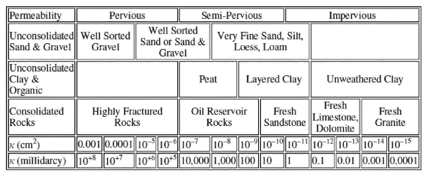
- Said preselected permeability may be of the same order of magnitude as the permeability of one or more of the layers in the earth which will be pierced by the borehole .
- K is the intrinsic permeability
- permeability can be expressed as wherein C is a dimensionless constant that is related to the configuration of the flow-paths, and d is the average, or effective pore diameter [length] .
- the permeable section 104 has a permeability to drilling fluid which is of the same order of magnitude as the permeability of one or more of the layers of the formation.
- a separate sensor may be used for each respective layer of the formation, thus enabling to match the permeability of the respective permeable section of the sensor to the permeability of the respective section of the borehole that is being drilled, thus improving the accuracy of the fluid loss sensor. Examples of the permeability are provided in table 1 above.
- the first valve 124 chokes the inflow of drilling fluid to allow a predetermined pressure difference across the permeable section 104.
- Said predetermined pressure difference may be
- the predetermined pressure difference may be in the range about of 5 to 50 bar, for instance about 10 to 15 bar.
- the pressure at the discharge end 118 of the flow rate sensor 116 may be equal to atmospheric pressure (i.e. about 1 bar) .
- a pressure in the annulus 112 and the sensor conduit 114 may therefore be slightly exceed 1 bar, for instance about in the range of 1.05 to 1.5 bar.
- the fluid pressure inside the permeable section 104 may be set in the range of about 5 to 50 bar.
- first valve 124 is controlled to set the pressure inside the permeable section 104 in the range of about 10 to 15 bar.
- the fluid pressure in the inflow line 52 during drilling may typically be in the range of 200 to 400 bar, and may be much higher, for instance up to 1200 bar.
- the permeable section 104 may have a length in the range of about 10 cm to 10 meter. The length may for instance be in the order of 2 meter. A diameter of the permeable section may be in the range of about 1 to 35 cm. In practice, the diameter of the permeable section may be several inches.
- Flow rate of drilling fluid from the first end 122 towards the second end 128 of the first pipe may be about 5 to 50 litre per minute [1/min], for instance about 10 1/min.
- flow rate in the corresponding fluid supply line 52 may be in the order of 1000 1/min.
- Flow rate at the flow rate sensor may be about 10 to 1000 ml/min, for instance about
- the permeable section may comprise a membrane suitable for pressure driven filtration.
- the membrane will have a pore size suitable for particle filtration.
- the pores or openings may have a diameter in the order of about 10 to 1000 ⁇ , for instance about 10 to 100 ⁇ .
- the permeable section may comprise a tangential flow membrane. Fouling is in principle limited due to the sweeping effects and shear rates of the passing fluid flow.
- the permeable section may be constructed from (synthetic) membrane devices such as flat plates, spiral wounds, and hollow fibers.
- the permeable section 104 may for instance comprise a pipe made of carbon steel, stainless steel or any suitable corrosion resistant metal or metal alloy. Said pipe may be provided with a number of openings to allow fluid passage. The number and the diameter of said openings enables to set the permeability of the permeable section at a predetermined value.
- the openings may for instance be made by laser perforation or by waterjet.
- the membrane may be constructed from spiral wounds which are constructed from flat membranes but in a form of a "pocket" containing two membrane sheets separated by a highly porous support plate.
- the membrane may also comprise a hollow fiber module, comprising an assembly of self-supporting fibers with a dense skin separation layer, and a more open matrix helping to withstand pressure gradients and maintain structural integrity.
- the hollow fiber module can contain up to 10, 000 fibers ranging from 200 to 2500 ⁇ m in diameter.
- the main advantage of a hollow fiber module is a relatively large surface area within an enclosed volume, increasing the efficiency of the separation process .
Landscapes
- Engineering & Computer Science (AREA)
- Geology (AREA)
- Mining & Mineral Resources (AREA)
- Life Sciences & Earth Sciences (AREA)
- Physics & Mathematics (AREA)
- Fluid Mechanics (AREA)
- General Life Sciences & Earth Sciences (AREA)
- Environmental & Geological Engineering (AREA)
- Geochemistry & Mineralogy (AREA)
- Mechanical Engineering (AREA)
- General Physics & Mathematics (AREA)
- Separation Using Semi-Permeable Membranes (AREA)
- Examining Or Testing Airtightness (AREA)
- Sampling And Sample Adjustment (AREA)
- Geophysics And Detection Of Objects (AREA)
Abstract
Description

Claims
Priority Applications (4)
| Application Number | Priority Date | Filing Date | Title |
|---|---|---|---|
| US14/904,928 US20160138955A1 (en) | 2013-07-16 | 2014-07-14 | Fluid loss sensor and method |
| CN201480040232.8A CN105378474A (en) | 2013-07-16 | 2014-07-14 | Fluid loss sensor and method |
| CA2917399A CA2917399A1 (en) | 2013-07-16 | 2014-07-14 | Fluid loss sensor and method |
| AU2014292239A AU2014292239B2 (en) | 2013-07-16 | 2014-07-14 | Fluid loss sensor and method |
Applications Claiming Priority (2)
| Application Number | Priority Date | Filing Date | Title |
|---|---|---|---|
| EP13176616 | 2013-07-16 | ||
| EP13176616.4 | 2013-07-16 |
Publications (1)
| Publication Number | Publication Date |
|---|---|
| WO2015007672A1 true WO2015007672A1 (en) | 2015-01-22 |
Family
ID=48783126
Family Applications (1)
| Application Number | Title | Priority Date | Filing Date |
|---|---|---|---|
| PCT/EP2014/065009 Ceased WO2015007672A1 (en) | 2013-07-16 | 2014-07-14 | Fluid loss sensor and method |
Country Status (5)
| Country | Link |
|---|---|
| US (1) | US20160138955A1 (en) |
| CN (1) | CN105378474A (en) |
| AU (1) | AU2014292239B2 (en) |
| CA (1) | CA2917399A1 (en) |
| WO (1) | WO2015007672A1 (en) |
Cited By (1)
| Publication number | Priority date | Publication date | Assignee | Title |
|---|---|---|---|---|
| WO2017106257A1 (en) * | 2015-12-14 | 2017-06-22 | Baker Hughes Incorporated | Fluid loss sensor |
Families Citing this family (5)
| Publication number | Priority date | Publication date | Assignee | Title |
|---|---|---|---|---|
| US10603607B2 (en) * | 2017-10-19 | 2020-03-31 | Saudi Arabian Oil Company | Method and apparatus for smart electromagnetic screen system for use in drilling operations |
| CN110043243B (en) * | 2019-04-18 | 2023-11-07 | 中国石油天然气集团有限公司 | Drilling fluid filtration loss measurement device and method |
| US12560070B2 (en) | 2020-10-09 | 2026-02-24 | Cnx Resources Corporation | Apparatus and method for three-phase separation at a well |
| US12560071B2 (en) | 2020-10-09 | 2026-02-24 | Cnx Resources Corporation | Apparatus and method for harnessing energy from a wellbore to perform multiple functions while reducing emissions |
| US12234713B2 (en) | 2022-06-29 | 2025-02-25 | Cnx Resources Corporation | Systems and method for efficient transport of fluid separators |
Citations (10)
| Publication number | Priority date | Publication date | Assignee | Title |
|---|---|---|---|---|
| US4184952A (en) * | 1978-05-12 | 1980-01-22 | Shell Oil Company | Measurement of BSW in crude oil streams |
| US4790933A (en) | 1986-11-18 | 1988-12-13 | Mobil Oil Corporation | Dynamic filtration unit and process of use |
| CN2119496U (en) * | 1992-02-25 | 1992-10-21 | 大庆石油管理局钻井研究所 | Circulating Drilling Fluid Dynamic Filter Loss Tester |
| US5361631A (en) | 1992-09-09 | 1994-11-08 | Halliburton Company | Apparatus and methods for determining the shear stress required for removing drilling fluid deposits |
| US20040014606A1 (en) * | 2002-07-19 | 2004-01-22 | Schlumberger Technology Corp | Method For Completing Injection Wells |
| WO2008118956A1 (en) * | 2007-03-26 | 2008-10-02 | M-I Llc | Method and apparatus for determining the properties of drilling fluids |
| WO2008144164A1 (en) | 2007-05-18 | 2008-11-27 | M-I Llc | Reusable filters for fluid loss measurements of drilling fluids |
| US20090217776A1 (en) | 2008-03-03 | 2009-09-03 | Jamison Dale E | Real-Time Filtration Apparatus and Associated Methods |
| WO2011095600A2 (en) | 2010-02-04 | 2011-08-11 | Statoil Asa | Method of conducting well operations |
| US20130032527A1 (en) * | 2011-04-08 | 2013-02-07 | Antonio Calleri | System of continuous sampling of filtration of a mud |
-
2014
- 2014-07-14 WO PCT/EP2014/065009 patent/WO2015007672A1/en not_active Ceased
- 2014-07-14 CA CA2917399A patent/CA2917399A1/en not_active Abandoned
- 2014-07-14 CN CN201480040232.8A patent/CN105378474A/en active Pending
- 2014-07-14 AU AU2014292239A patent/AU2014292239B2/en not_active Ceased
- 2014-07-14 US US14/904,928 patent/US20160138955A1/en not_active Abandoned
Patent Citations (10)
| Publication number | Priority date | Publication date | Assignee | Title |
|---|---|---|---|---|
| US4184952A (en) * | 1978-05-12 | 1980-01-22 | Shell Oil Company | Measurement of BSW in crude oil streams |
| US4790933A (en) | 1986-11-18 | 1988-12-13 | Mobil Oil Corporation | Dynamic filtration unit and process of use |
| CN2119496U (en) * | 1992-02-25 | 1992-10-21 | 大庆石油管理局钻井研究所 | Circulating Drilling Fluid Dynamic Filter Loss Tester |
| US5361631A (en) | 1992-09-09 | 1994-11-08 | Halliburton Company | Apparatus and methods for determining the shear stress required for removing drilling fluid deposits |
| US20040014606A1 (en) * | 2002-07-19 | 2004-01-22 | Schlumberger Technology Corp | Method For Completing Injection Wells |
| WO2008118956A1 (en) * | 2007-03-26 | 2008-10-02 | M-I Llc | Method and apparatus for determining the properties of drilling fluids |
| WO2008144164A1 (en) | 2007-05-18 | 2008-11-27 | M-I Llc | Reusable filters for fluid loss measurements of drilling fluids |
| US20090217776A1 (en) | 2008-03-03 | 2009-09-03 | Jamison Dale E | Real-Time Filtration Apparatus and Associated Methods |
| WO2011095600A2 (en) | 2010-02-04 | 2011-08-11 | Statoil Asa | Method of conducting well operations |
| US20130032527A1 (en) * | 2011-04-08 | 2013-02-07 | Antonio Calleri | System of continuous sampling of filtration of a mud |
Non-Patent Citations (4)
| Title |
|---|
| BEAR, JACOB, DYNAMICS OF FLUIDS IN POROUS MEDIA, 1972 |
| JOSE MIGUEL ARNAL; BEATRIZ GARCIA-FAYOS; MARIA SANCHO: "Membrane Cleaning, Expanding Issues in Desalination", 2011, INTECH |
| MOHAMMED ALOTAIBI: "CHARACTERISTICS AND REMOVAL OF FILTER CAKE FORMED BY FORMATE-BASED DRILLING MUD", 31 May 2008 (2008-05-31), XP055155102, Retrieved from the Internet <URL:http://repository.tamu.edu/bitstream/handle/1969.1/ETD-TAMU-2800/ALOTAIBI-THESIS.pdf?sequence=1.> [retrieved on 20141126] * |
| SAASEN A ET AL: "Automatic measurement of drilling fluid and drill cutting properties", IADC/SPE ASIA PACIFIC DRILLING TECHNOLOGY, SPE, US, 4 March 2008 (2008-03-04), pages 954 - 970, XP009123880 * |
Cited By (2)
| Publication number | Priority date | Publication date | Assignee | Title |
|---|---|---|---|---|
| WO2017106257A1 (en) * | 2015-12-14 | 2017-06-22 | Baker Hughes Incorporated | Fluid loss sensor |
| GB2562652A (en) * | 2015-12-14 | 2018-11-21 | Baker Hughes A Ge Co Llc | Fluid loss sensor |
Also Published As
| Publication number | Publication date |
|---|---|
| AU2014292239A1 (en) | 2016-01-28 |
| CA2917399A1 (en) | 2015-01-22 |
| US20160138955A1 (en) | 2016-05-19 |
| AU2014292239B2 (en) | 2016-11-17 |
| CN105378474A (en) | 2016-03-02 |
Similar Documents
| Publication | Publication Date | Title |
|---|---|---|
| AU2014292239B2 (en) | Fluid loss sensor and method | |
| US10167719B2 (en) | Methods and systems for evaluation of rock permeability, porosity, and fluid composition | |
| US20110220350A1 (en) | Identification of lost circulation zones | |
| Pandya et al. | Wellbore cleanout in inclined and horizontal wellbores: the effects of flow rate, fluid rheology, and solids density | |
| BRPI0813417B1 (en) | METHOD FOR DRILLING A DRILLING HOLE INSIDE AN UNDERGROUND FORMATION AND, DRILLING FLUID | |
| EA028646B1 (en) | System, method and device for analyzing drilling fluid | |
| US11255191B2 (en) | Methods to characterize wellbore fluid composition and provide optimal additive dosing using MEMS technology | |
| McCune | On-site testing to define injection-water quality requirements | |
| US11346195B2 (en) | Concurrent fluid injection and hydrocarbon production from a hydraulically fractured horizontal well | |
| US11255189B2 (en) | Methods to characterize subterranean fluid composition and adjust operating conditions using MEMS technology | |
| WO2015005998A1 (en) | Well fluid treatment apparatus | |
| CA2927689C (en) | Measuring critical shear stress for mud filtercake removal | |
| US9575047B2 (en) | Method of clay stabilization analysis | |
| US12252981B2 (en) | Systems for deploying downhole gas-lift tracers | |
| CN119466700B (en) | Large-scale on-site horizontal well multi-shower hole liquid and propping agent distribution testing method and modularized device | |
| RU2323335C2 (en) | Device to measure thermobaric liquid parameters in tubing string and annular space of well | |
| RU2422619C1 (en) | Procedure for treatment of bottomhole zone of well | |
| Fattouh et al. | PRODUCTION ENHANCEMENT BY REDUCING FORMATION DAMAGE OF AMAL FIELD | |
| Bitencourt Zimmermann | Experimental Investigation of Gravel-Pack Sizing Performance in Open-Hole Gravel-Pack (OHGP) Applications | |
| Heinerman | Design and Experiment Concept of a Cutting Transport Simulation Apparatus for Solid Shape Investigation | |
| Sifferman | The carrying capacity of drilling fluids | |
| Mikhailov | Acid placement and coverage in the acid jetting process | |
| CN115726712A (en) | Real-time slurry monitoring system | |
| Srivastava | Use of Intelligent Pumping System to Develop Reservoir Characterization | |
| RU2014447C1 (en) | Test method for unsteady filtration regime of injection wells |
Legal Events
| Date | Code | Title | Description |
|---|---|---|---|
| 121 | Ep: the epo has been informed by wipo that ep was designated in this application |
Ref document number: 14738834 Country of ref document: EP Kind code of ref document: A1 |
|
| ENP | Entry into the national phase |
Ref document number: 2917399 Country of ref document: CA |
|
| WWE | Wipo information: entry into national phase |
Ref document number: 14904928 Country of ref document: US |
|
| NENP | Non-entry into the national phase |
Ref country code: DE |
|
| ENP | Entry into the national phase |
Ref document number: 2014292239 Country of ref document: AU Date of ref document: 20140714 Kind code of ref document: A |
|
| 122 | Ep: pct application non-entry in european phase |
Ref document number: 14738834 Country of ref document: EP Kind code of ref document: A1 |