WO2014208575A1 - Video monitoring system, video processing device, video processing method, and video processing program - Google Patents
Video monitoring system, video processing device, video processing method, and video processing program Download PDFInfo
- Publication number
- WO2014208575A1 WO2014208575A1 PCT/JP2014/066777 JP2014066777W WO2014208575A1 WO 2014208575 A1 WO2014208575 A1 WO 2014208575A1 JP 2014066777 W JP2014066777 W JP 2014066777W WO 2014208575 A1 WO2014208575 A1 WO 2014208575A1
- Authority
- WO
- WIPO (PCT)
- Prior art keywords
- video
- category
- learning
- category information
- video data
- Prior art date
Links
Images


Classifications
-
- H—ELECTRICITY
- H04—ELECTRIC COMMUNICATION TECHNIQUE
- H04N—PICTORIAL COMMUNICATION, e.g. TELEVISION
- H04N5/00—Details of television systems
- H04N5/76—Television signal recording
-
- G—PHYSICS
- G06—COMPUTING; CALCULATING OR COUNTING
- G06F—ELECTRIC DIGITAL DATA PROCESSING
- G06F18/00—Pattern recognition
- G06F18/20—Analysing
- G06F18/21—Design or setup of recognition systems or techniques; Extraction of features in feature space; Blind source separation
- G06F18/217—Validation; Performance evaluation; Active pattern learning techniques
-
- G—PHYSICS
- G06—COMPUTING; CALCULATING OR COUNTING
- G06F—ELECTRIC DIGITAL DATA PROCESSING
- G06F18/00—Pattern recognition
- G06F18/40—Software arrangements specially adapted for pattern recognition, e.g. user interfaces or toolboxes therefor
-
- G—PHYSICS
- G06—COMPUTING; CALCULATING OR COUNTING
- G06V—IMAGE OR VIDEO RECOGNITION OR UNDERSTANDING
- G06V10/00—Arrangements for image or video recognition or understanding
- G06V10/94—Hardware or software architectures specially adapted for image or video understanding
- G06V10/945—User interactive design; Environments; Toolboxes
-
- G—PHYSICS
- G06—COMPUTING; CALCULATING OR COUNTING
- G06V—IMAGE OR VIDEO RECOGNITION OR UNDERSTANDING
- G06V20/00—Scenes; Scene-specific elements
- G06V20/40—Scenes; Scene-specific elements in video content
- G06V20/41—Higher-level, semantic clustering, classification or understanding of video scenes, e.g. detection, labelling or Markovian modelling of sport events or news items
-
- G—PHYSICS
- G06—COMPUTING; CALCULATING OR COUNTING
- G06V—IMAGE OR VIDEO RECOGNITION OR UNDERSTANDING
- G06V20/00—Scenes; Scene-specific elements
- G06V20/50—Context or environment of the image
- G06V20/52—Surveillance or monitoring of activities, e.g. for recognising suspicious objects
-
- H—ELECTRICITY
- H04—ELECTRIC COMMUNICATION TECHNIQUE
- H04N—PICTORIAL COMMUNICATION, e.g. TELEVISION
- H04N7/00—Television systems
- H04N7/18—Closed-circuit television [CCTV] systems, i.e. systems in which the video signal is not broadcast
- H04N7/181—Closed-circuit television [CCTV] systems, i.e. systems in which the video signal is not broadcast for receiving images from a plurality of remote sources
-
- G—PHYSICS
- G06—COMPUTING; CALCULATING OR COUNTING
- G06V—IMAGE OR VIDEO RECOGNITION OR UNDERSTANDING
- G06V20/00—Scenes; Scene-specific elements
- G06V20/40—Scenes; Scene-specific elements in video content
- G06V20/44—Event detection
-
- G—PHYSICS
- G08—SIGNALLING
- G08B—SIGNALLING OR CALLING SYSTEMS; ORDER TELEGRAPHS; ALARM SYSTEMS
- G08B13/00—Burglar, theft or intruder alarms
- G08B13/18—Actuation by interference with heat, light, or radiation of shorter wavelength; Actuation by intruding sources of heat, light, or radiation of shorter wavelength
- G08B13/189—Actuation by interference with heat, light, or radiation of shorter wavelength; Actuation by intruding sources of heat, light, or radiation of shorter wavelength using passive radiation detection systems
- G08B13/194—Actuation by interference with heat, light, or radiation of shorter wavelength; Actuation by intruding sources of heat, light, or radiation of shorter wavelength using passive radiation detection systems using image scanning and comparing systems
- G08B13/196—Actuation by interference with heat, light, or radiation of shorter wavelength; Actuation by intruding sources of heat, light, or radiation of shorter wavelength using passive radiation detection systems using image scanning and comparing systems using television cameras
- G08B13/19602—Image analysis to detect motion of the intruder, e.g. by frame subtraction
- G08B13/19613—Recognition of a predetermined image pattern or behaviour pattern indicating theft or intrusion
-
- G—PHYSICS
- G08—SIGNALLING
- G08B—SIGNALLING OR CALLING SYSTEMS; ORDER TELEGRAPHS; ALARM SYSTEMS
- G08B13/00—Burglar, theft or intruder alarms
- G08B13/18—Actuation by interference with heat, light, or radiation of shorter wavelength; Actuation by intruding sources of heat, light, or radiation of shorter wavelength
- G08B13/189—Actuation by interference with heat, light, or radiation of shorter wavelength; Actuation by intruding sources of heat, light, or radiation of shorter wavelength using passive radiation detection systems
- G08B13/194—Actuation by interference with heat, light, or radiation of shorter wavelength; Actuation by intruding sources of heat, light, or radiation of shorter wavelength using passive radiation detection systems using image scanning and comparing systems
- G08B13/196—Actuation by interference with heat, light, or radiation of shorter wavelength; Actuation by intruding sources of heat, light, or radiation of shorter wavelength using passive radiation detection systems using image scanning and comparing systems using television cameras
- G08B13/19665—Details related to the storage of video surveillance data
- G08B13/19671—Addition of non-video data, i.e. metadata, to video stream
-
- G—PHYSICS
- G08—SIGNALLING
- G08B—SIGNALLING OR CALLING SYSTEMS; ORDER TELEGRAPHS; ALARM SYSTEMS
- G08B13/00—Burglar, theft or intruder alarms
- G08B13/18—Actuation by interference with heat, light, or radiation of shorter wavelength; Actuation by intruding sources of heat, light, or radiation of shorter wavelength
- G08B13/189—Actuation by interference with heat, light, or radiation of shorter wavelength; Actuation by intruding sources of heat, light, or radiation of shorter wavelength using passive radiation detection systems
- G08B13/194—Actuation by interference with heat, light, or radiation of shorter wavelength; Actuation by intruding sources of heat, light, or radiation of shorter wavelength using passive radiation detection systems using image scanning and comparing systems
- G08B13/196—Actuation by interference with heat, light, or radiation of shorter wavelength; Actuation by intruding sources of heat, light, or radiation of shorter wavelength using passive radiation detection systems using image scanning and comparing systems using television cameras
- G08B13/19678—User interface
- G08B13/19691—Signalling events for better perception by user, e.g. indicating alarms by making display brighter, adding text, creating a sound
- G08B13/19693—Signalling events for better perception by user, e.g. indicating alarms by making display brighter, adding text, creating a sound using multiple video sources viewed on a single or compound screen
-
- H—ELECTRICITY
- H04—ELECTRIC COMMUNICATION TECHNIQUE
- H04N—PICTORIAL COMMUNICATION, e.g. TELEVISION
- H04N5/00—Details of television systems
- H04N5/76—Television signal recording
- H04N5/765—Interface circuits between an apparatus for recording and another apparatus
-
- H—ELECTRICITY
- H04—ELECTRIC COMMUNICATION TECHNIQUE
- H04N—PICTORIAL COMMUNICATION, e.g. TELEVISION
- H04N5/00—Details of television systems
- H04N5/76—Television signal recording
- H04N5/765—Interface circuits between an apparatus for recording and another apparatus
- H04N5/77—Interface circuits between an apparatus for recording and another apparatus between a recording apparatus and a television camera
- H04N5/772—Interface circuits between an apparatus for recording and another apparatus between a recording apparatus and a television camera the recording apparatus and the television camera being placed in the same enclosure
-
- H—ELECTRICITY
- H04—ELECTRIC COMMUNICATION TECHNIQUE
- H04N—PICTORIAL COMMUNICATION, e.g. TELEVISION
- H04N5/00—Details of television systems
- H04N5/76—Television signal recording
- H04N5/91—Television signal processing therefor
- H04N5/915—Television signal processing therefor for field- or frame-skip recording or reproducing
Definitions
- the present invention relates to a technique for analyzing video from a surveillance camera.
- Patent Document 1 discloses a technique that eliminates the need for prior knowledge and prior learning of a behavior recognition system by real-time learning.
- a certain behavior is characterized as normal or abnormal based on past observations of similar objects by machine learning of behavior recognition.
- the classifier learning cannot be performed in the operation process. That is, the analysis accuracy cannot be improved during actual operation of the behavior analysis system.
- An object of the present invention is to provide a technique for solving the above-described problems.
- a video processing apparatus provides: Video analysis means for analyzing video data captured by a surveillance camera, detecting an event belonging to a specific category, and outputting the detection result; Display control means for displaying a category setting screen for setting a category of an event included in the video together with the video of the video data; Learning data storage means for storing category information set in accordance with an operator's operation on the category setting screen as learning data together with the video data; With The video analysis means performs a learning process using the learning data stored in the learning data storage means.
- a video surveillance system includes: Video data storage means for storing video data captured by the surveillance camera; Analyzing the video data stored in the video data storage means, detecting an event belonging to a specific category, and outputting the detection result; Display control means for displaying a category setting screen for setting a category of an event included in the video together with the video of the video data stored in the video data storage means; Learning data storage means for storing category information set in accordance with an operator's operation on the category setting screen as learning data together with the video data; With The video analysis means performs a learning process using the learning data stored in the learning data storage means.
- a video processing method includes: A video analysis step of analyzing video data captured by a surveillance camera using a video analysis module, detecting an event belonging to a specific category, and outputting the detection result; A display control step for displaying a category setting screen for setting a category of an event included in the video together with the video of the video data; A learning data accumulation step for accumulating category information set according to an operator's operation on the category setting screen as learning data together with the video data; A learning step of performing learning processing of the video analysis module using the learning data stored in the learning data storage step; including.
- a video processing program provides: A video analysis step of analyzing video data captured by a surveillance camera using a video analysis module, detecting an event belonging to a specific category, and outputting the detection result; A display control step for displaying a category setting screen for setting a category of an event included in the video together with the video of the video data; A learning data accumulation step for accumulating category information set according to an operator's operation on the category setting screen as learning data together with the video data; A learning step of performing learning processing of the video analysis module using the learning data stored in the learning data storage step; Is executed on the computer.
- FIG. 1 shows the example of a display image of the video surveillance system which concerns on 2nd Embodiment of this invention. It is a flowchart which shows the flow of the learning process of the video surveillance system which concerns on 2nd Embodiment of this invention. It is a flowchart which shows the flow of the learning process of the video surveillance system which concerns on 2nd Embodiment of this invention. It is a block diagram which shows the structure of the video surveillance system which concerns on 3rd Embodiment of this invention. It is a block diagram which shows the content of the incentive table of the video surveillance system which concerns on 3rd Embodiment of this invention.
- the video processing apparatus 101 includes a video data storage unit 121, a video analysis unit 111, a display control unit 123, and a learning data storage unit 140.
- the video data storage unit 121 stores video data captured by the monitoring camera 102.
- the video analysis unit 111 analyzes the video data stored in the video data storage unit 121, detects an event belonging to specific category information, and outputs the detection result. Further, the display control unit 123 displays a category information setting screen for setting the category information of the events included in the video, together with the video data stored in the video data storage unit 121.
- the learning data storage unit 140 stores the category information set according to the operation of the operator 180 on the category information setting screen and the video data set with the category information as learning data. The video analysis unit 111 performs learning processing using the learning data stored in the learning data storage unit 140.
- the second embodiment of the present invention relates to a technique for collecting learning videos to be detected by the video detection engine by category, and using the collected learning videos for creating a new module and improving the accuracy of a default module.
- video is used as a concept including not only a moving image but also a still image.
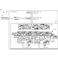
- FIG. 2A and 2B are diagrams for explaining a video monitoring system 200 as a prerequisite technology of the present embodiment.
- the video monitoring system 200 includes a data center 201 and a monitoring camera group 202.
- the data center 201 includes a video analysis platform 210 and a video monitoring platform 220, and further includes a plurality of video monitoring operation terminal groups 232.
- This figure shows a state of the video monitoring room 230 provided with a plurality of video monitoring operation terminal groups 232.
- the operator 240 checks the video to be monitored while looking at the two-screen monitor provided in each terminal of the video monitoring operation terminal group 232.
- 16-screen split display is performed on the left screen and 1-screen enlarged display is performed on the right screen.
- the present invention is not limited to this, and any display may be used.
- a plurality of large monitors 231 are provided on the wall in front of the video monitoring room 230, and a problematic video or still screen is displayed.
- 200 operators 240 monitor 16 cameras per person while switching, and continuously monitor images of all 2000 cameras for 24 hours and 360 days. Then, the operator 240 looks at the images of the 16 surveillance cameras assigned to him, and performs problematic actions such as runaway vehicles, dangerous objects such as guns and knives, theft, snatching, running away, injury cases, murders, drug trafficking, and illegal intrusions. , Discover events to be detected, such as equivalents and actions (such as suspicious individuals or crowd movements), and report them to the supervisor. The supervisor will review the footage and contact the police and hospital as necessary to help rescue the victim and arrest the criminal.
- the video monitoring platform 220 is called VMS (Video Management System) and stores video data acquired from the monitoring camera group 202 and distributes it to the video monitoring operation terminal group 232. As a result, the video monitoring operation terminal group 232 performs real-time display of video data in accordance with a predetermined allocation rule.
- the video monitoring platform 220 selects one of the monitoring camera groups 202 in response to a request from an operator 240 who operates the video monitoring operation terminal group 232, and sends a PTZ (pan / tilt / zoom) operation instruction.
- VMS Video Management System
- the video analysis platform 210 performs analysis processing on the video data stored in the video monitoring platform 220, and when there is video data that satisfies the conditions, the video monitoring platform 220 displays category information specifying the target video data. Send to.
- the video monitoring platform 220 generates an alert screen according to the category information received from the video analysis platform 210 and notifies a predetermined terminal of the video monitoring operation terminal group 232. In some cases, the problem video is forcibly enlarged and displayed on the large monitor 231.
- FIG. 2B is a block diagram showing a detailed configuration of the video monitoring system 200.
- the video monitoring platform 220 collects the video data 250 from the monitoring camera group 202, adds the collection time, camera position, camera ID, and other information, and stores them in the video storage 221.
- the camera selection operation unit 222 receives a camera designation and a PTZ (pan / tilt / zoom) operation instruction by the operator 240 via the video monitoring operation terminal group 232, and operates the designated surveillance camera.
- PTZ pan / tilt / zoom
- the video monitoring platform 220 includes a display control unit 223 that displays an alert on the video monitoring operation terminal group 232, and the reproduction / reproduction of past video stored in the video storage 221 in response to an instruction from the video monitoring operation terminal group 232.
- the video analysis platform 210 includes a default video analysis module 211.
- Each video analysis module is composed of algorithms and / or parameters for detecting different types of problem video.
- These default video analysis modules 211 perform video detection including a preset event using algorithms and parameters prepared in advance, and provide category information prepared in advance to the video monitoring platform for the detected video data. 220.
- FIG. 3 is a flowchart for explaining the flow of processing in the data center 201.
- the video monitoring platform 220 receives video data 250 from the monitoring camera group 202.
- step S302 the video monitoring platform 220 stores the received video data 250 in the video storage 221 and transmits it to the video monitoring operation terminal group 232 and the video analysis platform 210.
- step S303 the camera selection operation unit 222 receives camera selection information and camera operation information from the operator 240 via the video monitoring operation terminal group 232, and transmits an operation command to the selected monitoring camera. To do.
- step S304 the video analysis platform 210 uses the default video analysis module 211 to analyze the video data received from the video monitoring platform 220.
- step S305 when the default video analysis module 211 detects a video that satisfies a predetermined condition, the process proceeds to step S307, and category information is transmitted to the video monitoring platform 220. Even if a video satisfying the conditions is not detected, the process proceeds to step S310, and category information “no category information” is transmitted to the video monitoring platform 220.
- step S308 an alert screen is generated by the display control unit 223 of the video monitoring platform 220 and transmitted to the video monitoring operation terminal group 232 together with the video of the target monitoring camera.
- step S309 the operation of the operator 240 on the alert screen (report operation to the supervisor or the police) is accepted.
- FIG. 4 is a flowchart for explaining the flow of processing when the default video analysis module 211 is generated.
- the video analysis module generation processing here is performed before the data center 201 is built on site.
- step S401 a large amount of images including events to be detected are extracted from a large amount of past images with human eyes.
- an event similar to the event to be detected is intentionally generated in an environment similar to the actual operation environment, shooting is performed, and a sample video is extracted.
- additional information is manually added to each of a large amount of extracted / collected video data to create a learning video.
- the researcher / engineer selects an optimal algorithm for the target object, event, and action, and learns the learning video data to generate the default video analysis module 211.
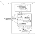
- FIG. 5 is a block diagram illustrating a configuration of a video monitoring system 500 as an example of a monitoring information processing system according to the present embodiment.
- the data center 501 as an example of the video processing apparatus according to the present embodiment includes a learning database 540 and a video monitoring operation terminal 570.
- the learning database 540 stores the learning video data 560 to which the category information 561 selected by the operator 240 is added.
- the video monitoring operation terminal 570 is a terminal for the supervisor 580 to specify category information.
- the video analysis platform 510 includes a new video analysis module 511, a category information addition unit 515, and a new video analysis module generation unit 516 that are newly created.
- the video monitoring platform 520 newly includes a learning video extraction unit 525.
- Category information is information indicating the classification of objects and actions to be detected in the video.
- the category information includes, for example, “handgun”, “knife”, “fight”, “runaway”, “motorcycle two-seater”, “drug trade”, and the like.
- the video analysis platform 510 includes category information tables 517 and 518, and various category information and their attributes are stored in association with each other.
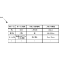
- FIG. 6A and 6B are diagrams showing the contents of the default category information table 517 and the new category information table 518.
- FIG. The category information tables 517 and 518 store the category information type, shape, trajectory information, size threshold value, and the like in association with the category information name.
- the video analysis modules 211 and 511 can determine the category of the event included in the video data.
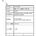
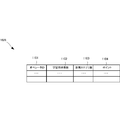
- FIG. 6C shows the contents of the category information 531 sent from the video monitoring operation terminal group 232 to the learning video extraction unit 525.
- “category”, “camera ID”, “video shooting time”, “event area”, “operator information”, and “category type” are registered as the category information 531.
- the “category” is the name of an object to be detected and the classification of an action.
- “Camera ID” is an identifier for identifying a surveillance camera.
- Video shooting time is information indicating the date and time when video data to which the category information is to be added was shot. It may represent a specific period (starting to end of collection).
- the “event area” is information indicating “target shape”, “video background difference”, and “position of background difference in the entire video” in the video.
- Various types of event areas such as a mask image, a background difference image, and a polygon image are prepared in addition to a rectangular area.
- “Operator information” indicates information of an operator to which category information has been added, and includes an operator ID, a name, and the like.
- the category type is the type of detection object / event.
- the category information “gun” is a category type in which the “shape” of the target gun is stored as learning video data.
- the category is “runaway”, it is a category information type for accumulating learning video data by setting the trajectory from the starting point to the ending point of the background difference in the designated area as “motion”. Furthermore, if the category information is “drug transaction”, it is a category information type in which the video data for learning is accumulated with the trajectory of the background difference in the entire video as “action”.
- the category adding unit 515 in the existing video analysis modules 211 and 511, if the category of events to be newly detected can be increased by adjusting or adding parameters, the video analysis of those events is performed. Parameters are adjusted or added to the modules 211 and 511. On the other hand, if it is determined that the event category to be newly detected cannot be increased by adjusting or adding the parameters of the existing video analysis modules 211 and 511, the new video analysis module generation unit 516 is used to create a new video. An analysis module 511 is generated. Further, the learning video data 560 stored in the learning database 540 is distributed to the video analysis modules 211 and 511 selected based on the category information 561, and each video analysis module performs a learning process.
- the display control unit 523 generates a category information selection screen 701 as shown in FIG. 7A and sends it to the video monitoring operation terminal group 232.
- the category information selection screen 701 includes category information prepared in advance (for example, “no helmet”, “two-seater motorcycle”, “overspeed”, “handgun”, “knife”, “drug trade”, “fight”, etc.) “Others” 711 is included as information options.
- category information prepared in advance for example, “no helmet”, “two-seater motorcycle”, “overspeed”, “handgun”, “knife”, “drug trade”, “fight”, etc.”
- “Others” 711 is included as information options.
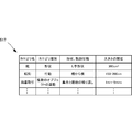
- a part of the category information candidates for example, five predicted in advance by referring to the camera event table 702 shown in FIG. It is preferable to display at 701.
- the camera event table 702 stores, for each camera ID 721, category information of events that are highly likely to be included in video captured by the camera. That is, the category 722 and the occurrence rate 723 of the event that has occurred are sequentially stored in descending order of occurrence rate.
- the category information regarding the selected category information is stored in the learning database 540 together with the video data for which the category information is selected.
- the learning video extraction unit 525 separately provides a learning database so that the supervisor 580 can appropriately input specific category information via the video monitoring operation terminal 570. Accumulate in 540.
- a category information input request is transmitted to the video monitoring operation terminal 570 for the supervisor 580 together with video identification information indicating the video data at that time.
- the operator 240 performs category information selection operation during video monitoring through the video monitoring operation terminal group 232
- the video identification information and category set 531 is stored in the learning database 540 via the video monitoring platform 520.
- the display control unit 523 transmits a new category information generation screen for prompting the supervisor 580 to generate new category information, to the video monitoring operation terminal 570.
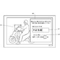
- FIG. 8 is a diagram showing a specific example of such a new category information setting screen 801.
- this new category information setting screen 801 for example, in addition to the category information name input field 811 and the category information type selection field 813, an area designation for designating an area to be noticed in order to detect a video included in the category information A graphic object 812 is prepared.
- information specifying the operator who selected the “other” category information, the location where the video was acquired, the time, and the like may be displayed. It may be determined to which category information the video categorized as “others” by video analysis is close to the video and presented to the supervisor 580.
- the new video analysis module generation unit 516 selects an existing algorithm that fits new category information, and creates a new video analysis module by a neural network or the like according to the algorithm. Further, learning is performed using the stored learning video data. As learning and application processing, either batch processing or on-the-fly processing can be selected in accordance with the category information.
- the category information adding unit 515 performs batch processing or real-time processing, registers information about the added category information in the category information table 518, and the default video analysis module 211 or the new video analysis module 511 receives the category information table 517.
- the category information to be referred to in 518 is designated.
- the default video analysis module 211 and the new video analysis module 511 perform learning processing using each learning video data based on the designated category information. Thereby, the video analysis accuracy of the default video analysis module 211 is improved, and the new video analysis module 511 is completed as a new video analysis module.
- the new video analysis module generation unit 516 recognizes a new algorithm (for example, even if a plurality of people pass in front of a person, the person behind is still a person) May be automatically generated.
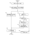
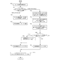
- FIG. Steps S301 to S309 are the same as the processing of the base technology described with reference to FIG. 3, so description thereof will be omitted here, and steps S900 to S911 after step S309 will be described.
- step S309 when the learning video extraction unit 525 examines the video and an alert is generated that the video includes an event to be detected, the process proceeds to step S900, and the display control unit 523 displays the alert in the video monitoring operation terminal group 232 as shown in FIG. A category information selection screen 701 as shown in 7A is displayed.
- step S901 the operator 240 selects category information. If the category information selected here is specific category information, the process proceeds to step S902, where the learning video extraction unit 525 generates category information, adds the category information to the video data, and generates learning video data. .
- step S903 the learning video extraction unit 525 stores the generated learning video data 540 in the learning database 540.
- step S904 the learning processing is performed by the default video analysis module 211.
- step S901 if the operator 240 selects the “other” category information in step S901, the process proceeds to step S905, where the learning video extraction unit 525 sets the category information name to “other” and the category information type to “NULL”. The category information is generated and assigned to the learning video data.
- step S906 the learning video extraction unit 525 stores the learning video data to which the category information “others” is added in the learning database 540, and at the same time, the display control unit 523 displays the video monitoring operation terminal 570 of the supervisor 580. The learning video data and the new category information setting screen 801 are sent to the user.
- step S907 the category adding unit 515 sets new category information in response to an instruction from the supervisor 580, and associates it with the stored learning video data.
- step S908 the category information adding unit 515 determines whether there is a default video analysis module 211 that fits the new category information that has been set. If there is a default video analysis module 211 that fits the set new category information, the process proceeds to step S909, where it is set as new category information of the target default video analysis module 211, and in step S904, a new category information is set. Learning is performed using video data for learning to which category information is attached.
- step S908 if there is no default video analysis module 211 that fits the set new category information, the process proceeds to step S911, where a new video analysis module 511 is generated and learned as a learning video. .
- FIG. 9B is a flowchart showing a detailed flow of the new video analysis module generation process in step S911.
- an algorithm database (not shown) is referred to.
- an algorithm for example, an algorithm for extracting a feature vector, an algorithm for extracting a cluster consisting of a set of blobs (small image areas) and an boundary of the cluster, etc.
- Generate a framework of the video analysis program module is selected according to the category information type specified by the supervisor.
- step S925 a video area to be analyzed by the video analysis module is set using the determination area specified by the supervisor.
- threshold values such as the shape and size of the object to be detected, the direction of movement to be detected, and the distance are determined using a plurality of learning video data.
- an object to be detected in the learning video data and a feature vector of the action may be extracted and the feature amount may be set as a threshold value.
- the feature amounts may be set as threshold values.
- the learning video can be easily accumulated during the actual operation by the operator, and the category can be attached at the same time.
- the semi-automatic learning video collection and the association with the category can be realized, and the man-hour and the period for the localization to the environment and the generation of the new video analysis module can be suppressed.
- FIG. 1 a video surveillance system according to a third embodiment of the present invention will be described.
- the video monitoring system according to the present embodiment is different from the second embodiment in that an incentive for the operator is taken into consideration. Since other configurations and operations are the same as those of the second embodiment, the same components are denoted by the same reference numerals and detailed description thereof is omitted here.
- FIG. 10 is a block diagram showing a configuration of the video monitoring system 1000 according to the present embodiment.
- the video monitoring platform 1020 included in the video monitoring system 1000 includes an incentive table 1026. Collecting efficiency is improved by collecting statistics on the number of learning videos accumulated in the learning database 540 for each incentive table 1026 and operators, and adding incentives.
- the incentive table 1026 stores and manages the number of videos for learning 1102, the number of new categories 1103, and the points 1104 in association with the operator ID 1101.
- the number of learning videos 1102 represents the number of learning video data selected and assigned by the operator.
- the number of new categories 1103 indicates the number of categories that the operator selects “Others” as a category and is finally generated as a new category by the supervisor. Since the number of learning videos and the number of new categories can be evaluated as the contribution value of the monitoring work by the operator, the point 1104 is calculated according to these values, and is also stored and updated in association with the operator ID. Weighting may be performed in consideration of the importance of the video that the operator has found and assigned the category when calculating the point 1104.
- a value representing the accuracy of category assignment may be used in addition to the point. For example, by showing test video data to which a correct category is given to a plurality of operators, verifying the detection speed, detection accuracy, and category correct probability of each operator, and using them to calculate an operator evaluation value Good.
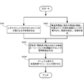
- FIG. 12 is a flowchart for explaining the flow of processing of the video monitoring system 1000.
- the process proceeds to step S1211 and points are given.
- points are given.
- incentives points according to the category of events discovered by the operator Is associated with the operator ID that has been categorized and stored.
- the display control unit 523 generates a category information selection screen 1301 as shown in FIG. 13 and sends it to the video monitoring operation terminal group 232.
- the category information selection screen 1301 includes a video display screen 1303, a category information bar 1302 indicating an alert occurrence status, and a video control component 1304 (for example, “play”, “stop”, “pause”, “rewind”, “fast forward”). Etc.), a progress bar 1307 representing the video reproduction status, and a category information setting button 1305 are included.
- the category information setting button 1305 includes “others” 1306 as options for category information, in addition to the category information prepared in advance.
- the operator 240 uses the video control component 1304 to check the video.
- the operator 240 corrects / adds the category information of the video data displayed on the display screen 1303 using the category information setting button 705.
- the category information regarding the category information set by the operator 240 is stored in the learning database 540 together with the video data.
- FIG. 14 is a flowchart for explaining the flow of processing by the video monitoring system 500.
- Steps S301 to S309 are the same as the processing of the base technology described with reference to FIG. 3, so description thereof will be omitted here, and steps S900 to S910 after step S309 will be described.
- Step S900, Step S902 to Step S910 are the same as the processing described in FIG. 9A, so description thereof will be omitted here and Step S1401 will be described.
- step S309 when the learning video extraction unit 525 examines the video and an alert is generated that the video includes an event to be detected, the process proceeds to step S900, and the display control unit 523 displays the alert in the video monitoring operation terminal group 232 as shown in FIG. A category information selection screen 1301 as shown in FIG. 13 is displayed.
- the video and its category information are displayed on the display unit 1303 and the category information bar 1302. Further, by using the video control component 1304, the category information and the video can be confirmed by playing, rewinding, and fast-forwarding.
- the category information bar 1302 displays the category information generated for the video displayed on the category information selection screen 1301 and the correct category information corrected and added by the operator 240 in color. For example, the section where the “no helmet” alert occurred is displayed in blue, the section where no alert is generated, or the section 1310 where there is no category information is displayed in black, and the “bike two-seater” alert is displayed. The generated section is displayed in red.
- the correct category information corrected and added by the operator 240 using the category information setting button 1305 is also displayed in the same manner.
- step S1401 the operator 240 uses the category information selection screen 1301 to check the video in which the alert has occurred and its category information, and corrects / adds the category information to a section where the category information needs to be corrected or added. .
- a category information setting button 1305 corresponding to specific category information is pressed while reproducing a part of the video. For example, suppose that the section where the “no helmet” alert is generated is corrected to the “two-seater bike” alert. Here, the section belonging to the category information “without helmet” is displayed in blue in the category information bar 1302. Using the video control component 1304 on the category information selection screen 1301, while reproducing the video on the display unit 1303, when the corresponding video data is displayed on the display unit 1303, the “Bike two people” of the category information setting button 1305 is displayed. Press the “Ride” button and change to the “Motorcycle two-seater” category. At this time, the color of the category information bar 1302 corresponding to the section in which the category information is set by the operator 240 changes from “blue” to “red”.
- a plurality of types of category information can be added to the same section using the video control component 1304.
- the category information bar 1302 in the section to which a plurality of category information is added is displayed in a layered manner with a plurality of colors. For example, when “no helmet” and “two-seater motorcycle” are added, blue and red are displayed in layers like a category information bar 1309.
- the “no category information” button 1308 may be pressed while reproducing the video of the section where the category information is to be deleted using the video control component 1304. This is the same as correcting the category information to “no category information”.
- the category information bar 1310 of the section corrected to “no category information” is displayed in black similarly to the section where no alert is generated.
- the specific button of the category information setting button 1305 may be kept pressed while the video in the corresponding section is being reproduced. Further, when the section for which category information correction / addition is desired is long, the switching of the category information setting button 1305 may be toggled so that the button is pushed only at the beginning and end of the section for which category information correction / addition is desired. .
- step S1401 when the operator corrects / adds correct category information, the video analysis module 211 can learn an alert to be output.
- step S902 the learning video extraction unit 525 adds the category information to the video data to generate learning video data.
- the operator can confirm the category information from the video and the monitoring information system, and the operator can set the correct category information so that a monitoring information system can be constructed to detect new objects and actions. Moreover, the accuracy of the monitoring information system can be improved by correcting the category information by the operator.
- the present invention may be applied to a system composed of a plurality of devices, or may be applied to a single device. Furthermore, the present invention can also be applied to a case where an information processing program that implements the functions of the embodiments is supplied directly or remotely to a system or apparatus. Therefore, in order to realize the functions of the present invention on a computer, a program installed on the computer, a medium storing the program, and a WWW (World Wide Web) server that downloads the program are also included in the scope of the present invention. . In particular, at least a non-transitory computer-readable medium that stores a program that causes a computer to execute the processing steps included in the above-described embodiments is included in the scope of the present invention.
Abstract
Description
監視カメラで撮影された映像データを解析して、特定のカテゴリに属する事象を検出し、その検出結果を出力する映像解析手段と、
前記映像データの映像と共に、前記映像に含まれる事象のカテゴリを設定するためのカテゴリ設定画面を表示させる表示制御手段と、
前記カテゴリ設定画面に対するオペレータの操作に応じて設定されたカテゴリ情報を、前記映像データと共に学習用データとして蓄積する学習用データ蓄積手段と、
を備え、
前記映像解析手段は前記学習用データ蓄積手段に蓄積された前記学習用データを用いて学習処理を行なう。 In order to achieve the above object, a video processing apparatus according to the present invention provides:
Video analysis means for analyzing video data captured by a surveillance camera, detecting an event belonging to a specific category, and outputting the detection result;
Display control means for displaying a category setting screen for setting a category of an event included in the video together with the video of the video data;
Learning data storage means for storing category information set in accordance with an operator's operation on the category setting screen as learning data together with the video data;
With
The video analysis means performs a learning process using the learning data stored in the learning data storage means.
監視カメラで撮影された映像データを蓄積する映像データ蓄積手段と、
前記映像データ蓄積手段に蓄積された映像データを解析して、特定のカテゴリに属する事象を検出し、その検出結果を出力する映像解析手段と、
前記映像データ蓄積手段に蓄積された映像データの映像と共に、前記映像に含まれる事象のカテゴリを設定するためのカテゴリ設定画面を表示させる表示制御手段と、
前記カテゴリ設定画面に対するオペレータの操作に応じて設定されたカテゴリ情報を、前記映像データと共に学習用データとして蓄積する学習用データ蓄積手段と、
を備え、
前記映像解析手段は前記学習用データ蓄積手段に蓄積された前記学習用データを用いて学習処理を行なう。 In order to achieve the above object, a video surveillance system according to the present invention includes:
Video data storage means for storing video data captured by the surveillance camera;
Analyzing the video data stored in the video data storage means, detecting an event belonging to a specific category, and outputting the detection result;
Display control means for displaying a category setting screen for setting a category of an event included in the video together with the video of the video data stored in the video data storage means;
Learning data storage means for storing category information set in accordance with an operator's operation on the category setting screen as learning data together with the video data;
With
The video analysis means performs a learning process using the learning data stored in the learning data storage means.
映像解析モジュールを用いて、監視カメラで撮影された映像データを解析して、特定のカテゴリに属する事象を検出し、その検出結果を出力する映像解析ステップと、
前記映像データの映像と共に、前記映像に含まれる事象のカテゴリを設定するためのカテゴリ設定画面を表示させる表示制御ステップと、
前記カテゴリ設定画面に対するオペレータの操作に応じて設定されたカテゴリ情報を、前記映像データと共に学習用データとして蓄積する学習用データ蓄積ステップと、
前記学習用データ蓄積ステップに蓄積された前記学習用データを用いて前記映像解析モジュールの学習処理を行なう学習ステップと、
を含む。 In order to achieve the above object, a video processing method according to the present invention includes:
A video analysis step of analyzing video data captured by a surveillance camera using a video analysis module, detecting an event belonging to a specific category, and outputting the detection result;
A display control step for displaying a category setting screen for setting a category of an event included in the video together with the video of the video data;
A learning data accumulation step for accumulating category information set according to an operator's operation on the category setting screen as learning data together with the video data;
A learning step of performing learning processing of the video analysis module using the learning data stored in the learning data storage step;
including.
映像解析モジュールを用いて、監視カメラで撮影された映像データを解析して、特定のカテゴリに属する事象を検出し、その検出結果を出力する映像解析ステップと、
前記映像データの映像と共に、前記映像に含まれる事象のカテゴリを設定するためのカテゴリ設定画面を表示させる表示制御ステップと、
前記カテゴリ設定画面に対するオペレータの操作に応じて設定されたカテゴリ情報を、前記映像データと共に学習用データとして蓄積する学習用データ蓄積ステップと、
前記学習用データ蓄積ステップに蓄積された前記学習用データを用いて前記映像解析モジュールの学習処理を行なう学習ステップと、
をコンピュータに実行させる。 In order to achieve the above object, a video processing program according to the present invention provides:
A video analysis step of analyzing video data captured by a surveillance camera using a video analysis module, detecting an event belonging to a specific category, and outputting the detection result;
A display control step for displaying a category setting screen for setting a category of an event included in the video together with the video of the video data;
A learning data accumulation step for accumulating category information set according to an operator's operation on the category setting screen as learning data together with the video data;
A learning step of performing learning processing of the video analysis module using the learning data stored in the learning data storage step;
Is executed on the computer.
本発明の第1実施形態としての映像処理装置101について、図1を用いて説明する。図1に示すように、映像処理装置101は、映像データ蓄積部121と映像解析部111と表示制御部123と学習用データ蓄積部140とを含む。 [First Embodiment]
A
本発明の第2実施形態は、映像検知エンジンの検知対象の学習用映像をカテゴリ別に収集し、収集した学習用映像を新規モジュール作成、既定モジュールの精度向上に活用する技術に関するものである。なお、以下の説明中「映像」という用語は、動画のみを意味する概念ではなく、静止画をも含む概念として用いている。 [Second Embodiment]
The second embodiment of the present invention relates to a technique for collecting learning videos to be detected by the video detection engine by category, and using the collected learning videos for creating a new module and improving the accuracy of a default module. In the following description, the term “video” is used as a concept including not only a moving image but also a still image.
まず、本発明の第2実施形態に係る映像監視システムの前提技術について、図2A~図4を用いて説明する。図2A、図2Bは、本実施形態の前提技術としての映像監視システム200を説明するための図である。 (Prerequisite technology)
First, the prerequisite technology of the video surveillance system according to the second embodiment of the present invention will be described with reference to FIGS. 2A to 4. FIG. 2A and 2B are diagrams for explaining a
上記前提技術では既定映像解析モジュールを作成する際、収集と正解付けに莫大な工数と期間を必要としていた。例えば、顔認証では2000枚の画像、ディープラーニングでの特定事象検知では100万枚の画像が必要であり、導入までのハードルが高かった。つまり、学習用映像からの映像解析モジュール(識別器)作成はマニュアルで実施され、その過程の中で映像解析モジュールの動作検証も個別に実施しており、個別に環境を整備していた為、工数と期間を必要としていた。 (Issues of prerequisite technologies)
In the base technology described above, enormous man-hours and time are required for collection and correct answer when creating the default video analysis module. For example, 2000 images were required for face authentication, and 1 million images were required for specific event detection in deep learning, and the hurdles until introduction were high. In other words, the video analysis module (discriminator) creation from the video for learning was performed manually, and the operation verification of the video analysis module was also performed individually in the process, and the environment was individually maintained, It required man-hours and duration.
図5は、本実施形態に係る監視情報処理システムの一例としての映像監視システム500の構成を示すブロック図である。前提技術と同様の構成には同じ符号を付して説明を省略する。図2Bに示した前提技術と異なり、本実施形態に係る映像処理装置の一例としてのデータセンタ501は、学習用データベース540と、映像監視操作端末570とを備える。学習用データベース540は、オペレータ240が選択したカテゴリ情報561を付加された学習用映像データ560を蓄積する。また、映像監視操作端末570は、スーパバイザ580がカテゴリ情報指定を行なうための端末である。映像解析プラットフォーム510は、新規に作成される新規映像解析モジュール511とカテゴリ情報追加部515と新規映像解析モジュール生成部516とを備える。一方、映像監視プラットフォーム520は、新たに学習用映像抽出部525を備える。 (Configuration of this embodiment)
FIG. 5 is a block diagram illustrating a configuration of a
図9A、図9Bは、映像監視システム500による処理の流れを説明するためのフローチャートである。ステップS301からステップS309までは、図3において説明した前提技術の処理と同様であるため、ここでは説明を省略し、ステップS309以降のステップS900~S911について説明する。 (Process flow)
9A and 9B are flowcharts for explaining the flow of processing by the
次に、本発明の第3実施形態に係る映像監視システムについて説明する。本実施形態に係る映像監視システムは、上記第2実施形態と比べると、オペレータに対するインセンティブを考慮する点で異なる。その他の構成および動作については、上記第2実施形態と同様であるため、同じ構成については同じ符号を付してここでは詳しい説明を省略する。 [Third Embodiment]
Next, a video surveillance system according to a third embodiment of the present invention will be described. The video monitoring system according to the present embodiment is different from the second embodiment in that an incentive for the operator is taken into consideration. Since other configurations and operations are the same as those of the second embodiment, the same components are denoted by the same reference numerals and detailed description thereof is omitted here.
をカテゴリ付けを行なったオペレータIDに紐付けて保存する。 FIG. 12 is a flowchart for explaining the flow of processing of the
Is associated with the operator ID that has been categorized and stored.
本手法の実施例として、監視情報システムの前提技術である図2Bのオペレータからのカテゴリ情報追加・修正を可能にしたシステムを説明する。 [Fourth Embodiment]
As an embodiment of the present technique, a system that enables addition / modification of category information from the operator of FIG. 2B, which is a prerequisite technology of the monitoring information system, will be described.
ステップS309において、学習用映像抽出部525が映像を精査し、検出すべき事象を含む映像であるというアラートが発生すると、ステップS900に進み、表示制御部523は、映像監視操作端末群232において図13に示すようなカテゴリ情報選択画面1301を表示する。 FIG. 14 is a flowchart for explaining the flow of processing by the
In step S309, when the learning
以上、実施形態を参照して本願発明を説明したが、本願発明は上記実施形態に限定されるものではない。本願発明の構成や詳細には、本願発明のスコープ内で当業者が理解し得る様々な変更をすることができる。また、それぞれの実施形態に含まれる別々の特徴を如何様に組み合わせたシステムまたは装置も、本発明の範疇に含まれる。 [Other Embodiments]
While the present invention has been described with reference to the embodiments, the present invention is not limited to the above embodiments. Various changes that can be understood by those skilled in the art can be made to the configuration and details of the present invention within the scope of the present invention. In addition, a system or an apparatus in which different features included in each embodiment are combined in any way is also included in the scope of the present invention.
Claims (9)
- 監視カメラで撮影された映像データを解析して、特定のカテゴリに属する事象を検出し、その検出結果を出力する映像解析手段と、
前記映像データの映像と共に、前記映像に含まれる事象のカテゴリを設定するためのカテゴリ設定画面を表示させる表示制御手段と、
前記カテゴリ設定画面に対するオペレータの操作に応じて設定されたカテゴリ情報を、前記映像データと共に学習用データとして蓄積する学習用データ蓄積手段と、
を備え、
前記映像解析手段は前記学習用データ蓄積手段に蓄積された前記学習用データを用いて学習処理を行なう映像処理装置。 Video analysis means for analyzing video data captured by a surveillance camera, detecting an event belonging to a specific category, and outputting the detection result;
Display control means for displaying a category setting screen for setting a category of an event included in the video together with the video of the video data;
Learning data storage means for storing category information set in accordance with an operator's operation on the category setting screen as learning data together with the video data;
With
The video processing device, wherein the video analysis means performs learning processing using the learning data stored in the learning data storage means. - 前記表示制御手段は、前記カテゴリ設定画面において、前記映像データに関連する複数のカテゴリを修正または追加可能に表示させる請求項1に記載の映像処理装置。 2. The video processing apparatus according to claim 1, wherein the display control means displays a plurality of categories related to the video data so that they can be corrected or added on the category setting screen.
- 前記表示制御手段は、前記カテゴリ設定画面において、前記映像データに関連する複数のカテゴリを選択可能に表示させる請求項1または2に記載の映像処理装置。 The video processing apparatus according to claim 1 or 2, wherein the display control means displays a plurality of categories related to the video data in a selectable manner on the category setting screen.
- 前記表示制御手段は、前記カテゴリ設定画面において、前記映像データに関連するカテゴリを新たに生成するために必要な情報を入力させる請求項1乃至3のいずれか1項に記載の映像処理装置。 4. The video processing apparatus according to claim 1, wherein the display control means inputs information necessary for newly generating a category related to the video data on the category setting screen.
- 前記カテゴリが新たに生成された場合に、新規なカテゴリの属する事象を検出するための映像解析手段を新たに生成する請求項1乃至4のいずれか1項に記載の映像処理装置。 The video processing apparatus according to any one of claims 1 to 4, wherein when the category is newly generated, video analysis means for detecting an event to which the new category belongs is newly generated.
- 前記映像解析手段は、学習用データ蓄積手段は、カテゴリ情報として、カテゴリ名、映像撮影時刻、事象領域、オペレータ情報を蓄積する請求項1乃至5のいずれか1項に記載の映像処理装置。 6. The video processing apparatus according to claim 1, wherein the video analysis unit stores a category name, a video shooting time, an event area, and operator information as category information.
- 監視カメラで撮影された映像データを蓄積する映像データ蓄積手段と、
前記映像データ蓄積手段に蓄積された映像データを解析して、特定のカテゴリに属する事象を検出し、その検出結果を出力する映像解析手段と、
前記映像データ蓄積手段に蓄積された映像データの映像と共に、前記映像に含まれる事象のカテゴリを設定するためのカテゴリ設定画面を表示させる表示制御手段と、
前記カテゴリ設定画面に対するオペレータの操作に応じて設定されたカテゴリ情報を、前記映像データと共に学習用データとして蓄積する学習用データ蓄積手段と、
を備え、
前記映像解析手段は前記学習用データ蓄積手段に蓄積された前記学習用データを用いて学習処理を行なう映像監視システム。 Video data storage means for storing video data captured by the surveillance camera;
Analyzing the video data stored in the video data storage means, detecting an event belonging to a specific category, and outputting the detection result;
Display control means for displaying a category setting screen for setting a category of an event included in the video together with the video of the video data stored in the video data storage means;
Learning data storage means for storing category information set in accordance with an operator's operation on the category setting screen as learning data together with the video data;
With
The video monitoring system, wherein the video analysis means performs a learning process using the learning data stored in the learning data storage means. - 映像解析モジュールを用いて、監視カメラで撮影された映像データを解析して、特定のカテゴリに属する事象を検出し、その検出結果を出力する映像解析ステップと、
前記映像データの映像と共に、前記映像に含まれる事象のカテゴリを設定するためのカテゴリ設定画面を表示させる表示制御ステップと、
前記カテゴリ設定画面に対するオペレータの操作に応じて設定されたカテゴリ情報を、前記映像データと共に学習用データとして蓄積する学習用データ蓄積ステップと、
前記学習用データ蓄積ステップに蓄積された前記学習用データを用いて前記映像解析モジュールの学習処理を行なう学習ステップと、
を含む映像処理方法。 A video analysis step of analyzing video data captured by a surveillance camera using a video analysis module, detecting an event belonging to a specific category, and outputting the detection result;
A display control step for displaying a category setting screen for setting a category of an event included in the video together with the video of the video data;
A learning data accumulation step for accumulating category information set according to an operator's operation on the category setting screen as learning data together with the video data;
A learning step of performing learning processing of the video analysis module using the learning data stored in the learning data storage step;
Video processing method. - 映像解析モジュールを用いて、監視カメラで撮影された映像データを解析して、特定のカテゴリに属する事象を検出し、その検出結果を出力する映像解析ステップと、
前記映像データの映像と共に、前記映像に含まれる事象のカテゴリを設定するためのカテゴリ設定画面を表示させる表示制御ステップと、
前記カテゴリ設定画面に対するオペレータの操作に応じて設定されたカテゴリ情報を、前記映像データと共に学習用データとして蓄積する学習用データ蓄積ステップと、
前記学習用データ蓄積ステップに蓄積された前記学習用データを用いて前記映像解析モジュールの学習処理を行なう学習ステップと、
をコンピュータに実行させる映像処理プログラム。
A video analysis step of analyzing video data captured by a surveillance camera using a video analysis module, detecting an event belonging to a specific category, and outputting the detection result;
A display control step for displaying a category setting screen for setting a category of an event included in the video together with the video of the video data;
A learning data accumulation step for accumulating category information set according to an operator's operation on the category setting screen as learning data together with the video data;
A learning step of performing learning processing of the video analysis module using the learning data stored in the learning data storage step;
A video processing program that causes a computer to execute.
Priority Applications (9)
| Application Number | Priority Date | Filing Date | Title |
|---|---|---|---|
| JP2015524069A JP6474107B2 (en) | 2013-06-28 | 2014-06-25 | Video monitoring system, video processing apparatus, video processing method, and video processing program |
| US14/899,191 US10275657B2 (en) | 2013-06-28 | 2014-06-25 | Video surveillance system, video processing apparatus, video processing method, and video processing program |
| US16/289,760 US11210526B2 (en) | 2013-06-28 | 2019-03-01 | Video surveillance system, video processing apparatus, video processing method, and video processing program |
| US17/527,446 US11729347B2 (en) | 2013-06-28 | 2021-11-16 | Video surveillance system, video processing apparatus, video processing method, and video processing program |
| US18/208,120 US20230319230A1 (en) | 2013-06-28 | 2023-06-09 | Video surveillance system, video processing apparatus, video processing method, and video processing program |
| US18/222,350 US20230362323A1 (en) | 2013-06-28 | 2023-07-14 | Video surveillance system, video processing apparatus, video processing method, and video processing program |
| US18/222,360 US20230362324A1 (en) | 2013-06-28 | 2023-07-14 | Video surveillance system, video processing apparatus, video processing method, and video processing program |
| US18/222,744 US20230362325A1 (en) | 2013-06-28 | 2023-07-17 | Video surveillance system, video processing apparatus, video processing method, and video processing program |
| US18/222,950 US20230362326A1 (en) | 2013-06-28 | 2023-07-17 | Video surveillance system, video processing apparatus, video processing method, and video processing program |
Applications Claiming Priority (2)
| Application Number | Priority Date | Filing Date | Title |
|---|---|---|---|
| JP2013136953 | 2013-06-28 | ||
| JP2013-136953 | 2013-06-28 |
Related Child Applications (2)
| Application Number | Title | Priority Date | Filing Date |
|---|---|---|---|
| US14/899,191 A-371-Of-International US10275657B2 (en) | 2013-06-28 | 2014-06-25 | Video surveillance system, video processing apparatus, video processing method, and video processing program |
| US16/289,760 Continuation US11210526B2 (en) | 2013-06-28 | 2019-03-01 | Video surveillance system, video processing apparatus, video processing method, and video processing program |
Publications (1)
| Publication Number | Publication Date |
|---|---|
| WO2014208575A1 true WO2014208575A1 (en) | 2014-12-31 |
Family
ID=52141907
Family Applications (1)
| Application Number | Title | Priority Date | Filing Date |
|---|---|---|---|
| PCT/JP2014/066777 WO2014208575A1 (en) | 2013-06-28 | 2014-06-25 | Video monitoring system, video processing device, video processing method, and video processing program |
Country Status (3)
| Country | Link |
|---|---|
| US (8) | US10275657B2 (en) |
| JP (6) | JP6474107B2 (en) |
| WO (1) | WO2014208575A1 (en) |
Cited By (9)
| Publication number | Priority date | Publication date | Assignee | Title |
|---|---|---|---|---|
| JPWO2016125420A1 (en) * | 2015-02-05 | 2017-08-31 | 株式会社リコー | Image processing apparatus, image processing system, image processing method, and program |
| JP2018033050A (en) * | 2016-08-25 | 2018-03-01 | 株式会社知能フレームワーク研究所 | State monitoring system |
| WO2020008711A1 (en) * | 2018-07-02 | 2020-01-09 | パナソニックIpマネジメント株式会社 | Learning device, learning system, and learning method |
| JP2020113945A (en) * | 2019-01-16 | 2020-07-27 | パナソニック株式会社 | Monitoring camera and detection method |
| CN111563425A (en) * | 2020-04-22 | 2020-08-21 | 蘑菇车联信息科技有限公司 | Traffic incident identification method and electronic equipment |
| US10950104B2 (en) | 2019-01-16 | 2021-03-16 | PANASONIC l-PRO SENSING SOLUTIONS CO., LTD. | Monitoring camera and detection method |
| JP2021182413A (en) * | 2015-09-30 | 2021-11-25 | 日本電気株式会社 | System, abnormality determination device and method |
| JP2021532478A (en) * | 2018-07-23 | 2021-11-25 | エムピー・ハイ・テック・ソリューションズ・ピーティワイ・リミテッドMp High Tech Solutions Pty Ltd | User interface for configuring a thermal imaging system |
| JP2022550548A (en) * | 2019-09-29 | 2022-12-02 | ザックダン カンパニー | OBJECT RECOGNITION METHOD AND APPARATUS IN IMAGE USING MACHINE LEARNING |
Families Citing this family (19)
| Publication number | Priority date | Publication date | Assignee | Title |
|---|---|---|---|---|
| US20160113345A1 (en) * | 2013-06-18 | 2016-04-28 | Alexandr Alexandrovich KOLOTOV | Helmet for motorcyclists and for people who engage in extreme activities |
| US10997422B2 (en) * | 2016-01-29 | 2021-05-04 | Nec Corporation | Information processing apparatus, information processing method, and program |
| JP6737290B2 (en) * | 2016-01-29 | 2020-08-05 | 日本電気株式会社 | Information processing apparatus, information processing method, and program |
| EP3340104B1 (en) * | 2016-12-21 | 2023-11-29 | Axis AB | A method for generating alerts in a video surveillance system |
| US10623680B1 (en) * | 2017-07-11 | 2020-04-14 | Equinix, Inc. | Data center viewing system |
| CN107846578A (en) * | 2017-10-30 | 2018-03-27 | 北京小米移动软件有限公司 | information subscribing method and device |
| JP6887132B2 (en) * | 2018-04-12 | 2021-06-16 | パナソニックIpマネジメント株式会社 | Video processing equipment, video processing system and video processing method |
| KR102015945B1 (en) * | 2018-04-19 | 2019-08-28 | 주식회사 크라우드웍스 | Method for packaging learning images for atonomous vehicle and apparatus thereof |
| JP2020005014A (en) | 2018-06-25 | 2020-01-09 | パナソニック株式会社 | Information processing system, video text conversion method, and video data generation method |
| US10839220B2 (en) * | 2018-10-15 | 2020-11-17 | Kepler Vision Technologies B.V. | Method for categorizing a scene comprising a sub-scene with machine learning |
| WO2020100438A1 (en) * | 2018-11-13 | 2020-05-22 | ソニー株式会社 | Information processing device, information processing method, and program |
| JP7320222B2 (en) * | 2018-11-26 | 2023-08-03 | 公立大学法人北九州市立大学 | Bathroom monitoring device and bathroom monitoring method |
| US11763561B2 (en) * | 2018-12-26 | 2023-09-19 | Nec Corporation | Information processing apparatus, information processing method, and program |
| JP6742623B1 (en) * | 2019-11-13 | 2020-08-19 | 尚範 伊達 | Monitoring device, monitoring method, and program |
| JPWO2021111704A1 (en) * | 2019-12-02 | 2021-06-10 | ||
| JP2022048475A (en) * | 2020-09-15 | 2022-03-28 | 株式会社日立製作所 | Video analyzing system and video analyzing method |
| JP7415872B2 (en) * | 2020-10-23 | 2024-01-17 | 横河電機株式会社 | Apparatus, system, method and program |
| US11354994B1 (en) * | 2021-05-04 | 2022-06-07 | Motorola Solutions, Inc. | Analytics for planning an upgrade to a video camera surveillance system |
| CN113850144A (en) * | 2021-08-30 | 2021-12-28 | 湖南黑鲸数据科技有限公司 | Video reliability automatic inspection system based on image recognition |
Citations (4)
| Publication number | Priority date | Publication date | Assignee | Title |
|---|---|---|---|---|
| JPH0728766A (en) * | 1993-06-24 | 1995-01-31 | Toshiba Corp | Pattern recognition system and monitor system |
| JP2000057349A (en) * | 1998-08-10 | 2000-02-25 | Hitachi Ltd | Method for sorting defect, device therefor and method for generating data for instruction |
| JP2006148442A (en) * | 2004-11-18 | 2006-06-08 | Toshiba Corp | Mobile monitoring apparatus |
| JP2008250908A (en) * | 2007-03-30 | 2008-10-16 | Toshiba Corp | Picture discriminating method and device |
Family Cites Families (25)
| Publication number | Priority date | Publication date | Assignee | Title |
|---|---|---|---|---|
| JP3967406B2 (en) * | 1996-11-01 | 2007-08-29 | 日本電子株式会社 | Parts inspection system |
| JP4132229B2 (en) | 1998-06-03 | 2008-08-13 | 株式会社ルネサステクノロジ | Defect classification method |
| JP4267103B2 (en) * | 1998-09-18 | 2009-05-27 | 株式会社日立製作所 | Appearance image classification apparatus and method |
| US20040075738A1 (en) * | 1999-05-12 | 2004-04-22 | Sean Burke | Spherical surveillance system architecture |
| JP3617937B2 (en) | 1999-06-30 | 2005-02-09 | 株式会社東芝 | Image monitoring method and image monitoring apparatus |
| GB9918248D0 (en) | 1999-08-04 | 1999-10-06 | Matra Bae Dynamics Uk Ltd | Improvements in and relating to surveillance systems |
| JP2000099743A (en) | 1999-09-28 | 2000-04-07 | Hitachi Ltd | Display device for moving image and recording medium storing program for the display device |
| JP4660879B2 (en) * | 2000-04-27 | 2011-03-30 | ソニー株式会社 | Information providing apparatus and method, and program |
| JP2002032751A (en) | 2000-07-18 | 2002-01-31 | Olympus Optical Co Ltd | Learning type image classifying device and method and recording medium with its processing program recorded thereon |
| JP2004178258A (en) | 2002-11-27 | 2004-06-24 | Mitsubishi Heavy Ind Ltd | Port security system |
| JP3906854B2 (en) | 2004-07-07 | 2007-04-18 | 株式会社日立製作所 | Method and apparatus for detecting feature scene of moving image |
| EP1969525A1 (en) * | 2005-12-23 | 2008-09-17 | Ingenia Holdings (UK)Limited | Optical authentication |
| WO2008098188A2 (en) * | 2007-02-08 | 2008-08-14 | Behavioral Recognition Systems, Inc. | Behavioral recognition system |
| US8295597B1 (en) * | 2007-03-14 | 2012-10-23 | Videomining Corporation | Method and system for segmenting people in a physical space based on automatic behavior analysis |
| JP2011028689A (en) | 2009-07-29 | 2011-02-10 | Sony Corp | Moving image extraction device, program and moving image extraction method |
| JP5289290B2 (en) | 2009-11-27 | 2013-09-11 | セコム株式会社 | Posture estimation device |
| JP2011133984A (en) * | 2009-12-22 | 2011-07-07 | Panasonic Corp | Motion feature extraction device and motion feature extraction method |
| JP5545877B2 (en) * | 2011-01-28 | 2014-07-09 | 日本電信電話株式会社 | Content recognition model learning apparatus, content recognition model learning method, and content recognition model learning program |
| JP5738028B2 (en) | 2011-03-25 | 2015-06-17 | セコム株式会社 | Video processing device |
| JP5214762B2 (en) * | 2011-03-25 | 2013-06-19 | 株式会社東芝 | Recognition device, method and program |
| JP5492139B2 (en) * | 2011-04-27 | 2014-05-14 | 富士フイルム株式会社 | Image compression apparatus, image expansion apparatus, method, and program |
| WO2012176317A1 (en) * | 2011-06-23 | 2012-12-27 | サイバーアイ・エンタテインメント株式会社 | Image recognition system-equipped interest graph collection system using relationship search |
| JPWO2013039025A1 (en) * | 2011-09-16 | 2015-03-26 | Necカシオモバイルコミュニケーションズ株式会社 | Information processing apparatus with information management editing function |
| JP5866728B2 (en) | 2011-10-14 | 2016-02-17 | サイバーアイ・エンタテインメント株式会社 | Knowledge information processing server system with image recognition system |
| JP5743849B2 (en) * | 2011-10-27 | 2015-07-01 | 株式会社日立製作所 | Video analysis apparatus and system |
-
2014
- 2014-06-25 US US14/899,191 patent/US10275657B2/en active Active
- 2014-06-25 WO PCT/JP2014/066777 patent/WO2014208575A1/en active Application Filing
- 2014-06-25 JP JP2015524069A patent/JP6474107B2/en active Active
-
2017
- 2017-06-16 JP JP2017118616A patent/JP6555547B2/en active Active
-
2019
- 2019-03-01 US US16/289,760 patent/US11210526B2/en active Active
- 2019-04-11 JP JP2019075386A patent/JP7014440B2/en active Active
-
2020
- 2020-12-01 JP JP2020199926A patent/JP7036186B2/en active Active
-
2021
- 2021-11-16 US US17/527,446 patent/US11729347B2/en active Active
-
2022
- 2022-03-03 JP JP2022032816A patent/JP7359237B2/en active Active
-
2023
- 2023-06-09 US US18/208,120 patent/US20230319230A1/en active Pending
- 2023-07-14 US US18/222,360 patent/US20230362324A1/en active Pending
- 2023-07-14 US US18/222,350 patent/US20230362323A1/en active Pending
- 2023-07-17 US US18/222,950 patent/US20230362326A1/en active Pending
- 2023-07-17 US US18/222,744 patent/US20230362325A1/en active Pending
- 2023-09-28 JP JP2023168332A patent/JP2024009835A/en active Pending
Patent Citations (4)
| Publication number | Priority date | Publication date | Assignee | Title |
|---|---|---|---|---|
| JPH0728766A (en) * | 1993-06-24 | 1995-01-31 | Toshiba Corp | Pattern recognition system and monitor system |
| JP2000057349A (en) * | 1998-08-10 | 2000-02-25 | Hitachi Ltd | Method for sorting defect, device therefor and method for generating data for instruction |
| JP2006148442A (en) * | 2004-11-18 | 2006-06-08 | Toshiba Corp | Mobile monitoring apparatus |
| JP2008250908A (en) * | 2007-03-30 | 2008-10-16 | Toshiba Corp | Picture discriminating method and device |
Cited By (16)
| Publication number | Priority date | Publication date | Assignee | Title |
|---|---|---|---|---|
| JPWO2016125420A1 (en) * | 2015-02-05 | 2017-08-31 | 株式会社リコー | Image processing apparatus, image processing system, image processing method, and program |
| JP2021182413A (en) * | 2015-09-30 | 2021-11-25 | 日本電気株式会社 | System, abnormality determination device and method |
| JP7160154B2 (en) | 2015-09-30 | 2022-10-25 | 日本電気株式会社 | System, abnormality determination device and method |
| JP2018033050A (en) * | 2016-08-25 | 2018-03-01 | 株式会社知能フレームワーク研究所 | State monitoring system |
| US11436439B2 (en) | 2018-07-02 | 2022-09-06 | Panasonic Intellectual Property Management Co., Ltd. | System and method for generating label candidates related to recognition target for selection and learning |
| WO2020008711A1 (en) * | 2018-07-02 | 2020-01-09 | パナソニックIpマネジメント株式会社 | Learning device, learning system, and learning method |
| JP2020008905A (en) * | 2018-07-02 | 2020-01-16 | パナソニックIpマネジメント株式会社 | Learning apparatus, learning system and learning method |
| JP7308421B2 (en) | 2018-07-02 | 2023-07-14 | パナソニックIpマネジメント株式会社 | LEARNING DEVICE, LEARNING SYSTEM AND LEARNING METHOD |
| JP7303288B2 (en) | 2018-07-23 | 2023-07-04 | エムピー・ハイ・テック・ソリューションズ・ピーティワイ・リミテッド | User interface for configuring the thermal imaging system |
| JP2021532478A (en) * | 2018-07-23 | 2021-11-25 | エムピー・ハイ・テック・ソリューションズ・ピーティワイ・リミテッドMp High Tech Solutions Pty Ltd | User interface for configuring a thermal imaging system |
| JP2020113945A (en) * | 2019-01-16 | 2020-07-27 | パナソニック株式会社 | Monitoring camera and detection method |
| US11380177B2 (en) | 2019-01-16 | 2022-07-05 | Panasonic I-Pro Sensing Solutions Co., Ltd. | Monitoring camera and detection method |
| US10950104B2 (en) | 2019-01-16 | 2021-03-16 | PANASONIC l-PRO SENSING SOLUTIONS CO., LTD. | Monitoring camera and detection method |
| JP2022550548A (en) * | 2019-09-29 | 2022-12-02 | ザックダン カンパニー | OBJECT RECOGNITION METHOD AND APPARATUS IN IMAGE USING MACHINE LEARNING |
| CN111563425B (en) * | 2020-04-22 | 2023-04-07 | 蘑菇车联信息科技有限公司 | Traffic incident identification method and electronic equipment |
| CN111563425A (en) * | 2020-04-22 | 2020-08-21 | 蘑菇车联信息科技有限公司 | Traffic incident identification method and electronic equipment |
Also Published As
| Publication number | Publication date |
|---|---|
| JP2021061598A (en) | 2021-04-15 |
| JP2017225122A (en) | 2017-12-21 |
| US20230319230A1 (en) | 2023-10-05 |
| JP7359237B2 (en) | 2023-10-11 |
| US20190197319A1 (en) | 2019-06-27 |
| JP6555547B2 (en) | 2019-08-07 |
| US11210526B2 (en) | 2021-12-28 |
| JP6474107B2 (en) | 2019-02-27 |
| US20160132731A1 (en) | 2016-05-12 |
| US20230362326A1 (en) | 2023-11-09 |
| US20230362325A1 (en) | 2023-11-09 |
| JP2019192227A (en) | 2019-10-31 |
| JPWO2014208575A1 (en) | 2017-02-23 |
| US10275657B2 (en) | 2019-04-30 |
| JP7014440B2 (en) | 2022-02-01 |
| JP7036186B2 (en) | 2022-03-15 |
| JP2024009835A (en) | 2024-01-23 |
| US11729347B2 (en) | 2023-08-15 |
| US20220076028A1 (en) | 2022-03-10 |
| US20230362323A1 (en) | 2023-11-09 |
| US20230362324A1 (en) | 2023-11-09 |
| JP2022095617A (en) | 2022-06-28 |
Similar Documents
| Publication | Publication Date | Title |
|---|---|---|
| JP6555547B2 (en) | Video monitoring system, video processing apparatus, video processing method, and video processing program | |
| CN109858365B (en) | Special crowd gathering behavior analysis method and device and electronic equipment | |
| US11328163B2 (en) | Methods and apparatus for automated surveillance systems | |
| JP2015070401A (en) | Image processing apparatus, image processing method, and image processing program | |
| US9870684B2 (en) | Information processing apparatus, information processing method, program, and information processing system for achieving a surveillance camera system | |
| US20160019427A1 (en) | Video surveillence system for detecting firearms | |
| US10635908B2 (en) | Image processing system and image processing method | |
| KR102149832B1 (en) | Automated Violence Detecting System based on Deep Learning | |
| KR102174784B1 (en) | Method for Recognizing and Tracking Large-scale Object using Deep learning and Multi-Agent | |
| CN108701393A (en) | System and method for event handling | |
| JP5088463B2 (en) | Monitoring system | |
| CN115567690A (en) | Intelligent monitoring system capable of automatically identifying dangerous points of field operation | |
| KR20200059643A (en) | ATM security system based on image analyses and the method thereof | |
| JP2015019296A (en) | Image processing system, image processing method, and image processing program | |
| JP6806626B2 (en) | Person group tracking device and person group tracking method | |
| CN114418388A (en) | Personnel management method and device based on image recognition and storage medium | |
| TWI784718B (en) | Method and system for processing alarm event in factory | |
| KR20140052744A (en) | Method and apparatus for searching event occurred in image | |
| CN117354469B (en) | District monitoring video target tracking method and system based on security precaution | |
| CN116977912A (en) | Data processing method, device, computer equipment and readable storage medium |
Legal Events
| Date | Code | Title | Description |
|---|---|---|---|
| 121 | Ep: the epo has been informed by wipo that ep was designated in this application |
Ref document number: 14817516 Country of ref document: EP Kind code of ref document: A1 |
|
| ENP | Entry into the national phase |
Ref document number: 2015524069 Country of ref document: JP Kind code of ref document: A |
|
| WWE | Wipo information: entry into national phase |
Ref document number: 14899191 Country of ref document: US |
|
| NENP | Non-entry into the national phase |
Ref country code: DE |
|
| 122 | Ep: pct application non-entry in european phase |
Ref document number: 14817516 Country of ref document: EP Kind code of ref document: A1 |