WO2014196129A1 - 障害分析装置、障害分析方法、および、記録媒体 - Google Patents
障害分析装置、障害分析方法、および、記録媒体 Download PDFInfo
- Publication number
- WO2014196129A1 WO2014196129A1 PCT/JP2014/002569 JP2014002569W WO2014196129A1 WO 2014196129 A1 WO2014196129 A1 WO 2014196129A1 JP 2014002569 W JP2014002569 W JP 2014002569W WO 2014196129 A1 WO2014196129 A1 WO 2014196129A1
- Authority
- WO
- WIPO (PCT)
- Prior art keywords
- information
- pattern
- log
- system component
- unit
- Prior art date
- Legal status (The legal status is an assumption and is not a legal conclusion. Google has not performed a legal analysis and makes no representation as to the accuracy of the status listed.)
- Ceased
Links
Images








Classifications
-
- G—PHYSICS
- G06—COMPUTING OR CALCULATING; COUNTING
- G06F—ELECTRIC DIGITAL DATA PROCESSING
- G06F11/00—Error detection; Error correction; Monitoring
- G06F11/07—Responding to the occurrence of a fault, e.g. fault tolerance
- G06F11/0703—Error or fault processing not based on redundancy, i.e. by taking additional measures to deal with the error or fault not making use of redundancy in operation, in hardware, or in data representation
- G06F11/079—Root cause analysis, i.e. error or fault diagnosis
-
- G—PHYSICS
- G06—COMPUTING OR CALCULATING; COUNTING
- G06F—ELECTRIC DIGITAL DATA PROCESSING
- G06F11/00—Error detection; Error correction; Monitoring
- G06F11/07—Responding to the occurrence of a fault, e.g. fault tolerance
- G06F11/0703—Error or fault processing not based on redundancy, i.e. by taking additional measures to deal with the error or fault not making use of redundancy in operation, in hardware, or in data representation
- G06F11/0706—Error or fault processing not based on redundancy, i.e. by taking additional measures to deal with the error or fault not making use of redundancy in operation, in hardware, or in data representation the processing taking place on a specific hardware platform or in a specific software environment
-
- G—PHYSICS
- G06—COMPUTING OR CALCULATING; COUNTING
- G06F—ELECTRIC DIGITAL DATA PROCESSING
- G06F11/00—Error detection; Error correction; Monitoring
- G06F11/07—Responding to the occurrence of a fault, e.g. fault tolerance
- G06F11/0703—Error or fault processing not based on redundancy, i.e. by taking additional measures to deal with the error or fault not making use of redundancy in operation, in hardware, or in data representation
- G06F11/0706—Error or fault processing not based on redundancy, i.e. by taking additional measures to deal with the error or fault not making use of redundancy in operation, in hardware, or in data representation the processing taking place on a specific hardware platform or in a specific software environment
- G06F11/0709—Error or fault processing not based on redundancy, i.e. by taking additional measures to deal with the error or fault not making use of redundancy in operation, in hardware, or in data representation the processing taking place on a specific hardware platform or in a specific software environment in a distributed system consisting of a plurality of standalone computer nodes, e.g. clusters, client-server systems
-
- G—PHYSICS
- G06—COMPUTING OR CALCULATING; COUNTING
- G06F—ELECTRIC DIGITAL DATA PROCESSING
- G06F11/00—Error detection; Error correction; Monitoring
- G06F11/07—Responding to the occurrence of a fault, e.g. fault tolerance
- G06F11/0703—Error or fault processing not based on redundancy, i.e. by taking additional measures to deal with the error or fault not making use of redundancy in operation, in hardware, or in data representation
- G06F11/0751—Error or fault detection not based on redundancy
-
- G—PHYSICS
- G06—COMPUTING OR CALCULATING; COUNTING
- G06F—ELECTRIC DIGITAL DATA PROCESSING
- G06F11/00—Error detection; Error correction; Monitoring
- G06F11/07—Responding to the occurrence of a fault, e.g. fault tolerance
- G06F11/0703—Error or fault processing not based on redundancy, i.e. by taking additional measures to deal with the error or fault not making use of redundancy in operation, in hardware, or in data representation
- G06F11/0766—Error or fault reporting or storing
- G06F11/0787—Storage of error reports, e.g. persistent data storage, storage using memory protection
Definitions
- the present invention relates to a technique for analyzing a failure in an information processing system.
- the fault analysis system described in Patent Document 1 holds a normal pattern of a processing sequence and an abnormal pattern at the time of a fault.
- the failure analysis system acquires a processing sequence pattern (search pattern) and analyzes the failure by collating with a normal pattern and an abnormal pattern.
- search pattern processing sequence pattern
- This failure analysis system determines that it is operating normally when the search pattern matches the normal pattern. Further, when the search pattern matches the abnormal pattern, the failure analysis system presents information regarding the abnormal pattern.
- this failure analysis system holds a new abnormal pattern when the search pattern does not match the normal pattern or the abnormal pattern.
- the failure analysis system described in Patent Document 2 records a normal pattern and the number of occurrences for each period of messages collected in the learning mode during normal operation of the information processing system. Then, this failure analysis system detects abnormalities when there is no normal pattern that matches the pattern of messages collected in the operation mode, or when the number of occurrences is above or below the upper limit based on the number of occurrences of the normal pattern. Is determined to have been detected.
- the failure analysis system described in Patent Document 3 detects a failure by checking whether or not a message pattern obtained at the time of a failure that occurred in the past matches a message pattern obtained at the time of operation.
- This failure analysis system for example, accumulates message patterns at the time of past failures in a certain information processing system, and detects failures in other information processing systems by collating with message patterns obtained during operation of other information processing systems. .
- this failure analysis system performs collation by increasing the abstraction level for portions that do not match between message patterns during collation.
- JP 2006-59266 A Japanese Patent No. 4944391 JP 2012-141802 A JP 2012-123694 A
- the failure analysis system described in Patent Document 1 needs to maintain a normal pattern and an abnormal pattern of a processing sequence for failure analysis.
- products of a plurality of development companies are often used in combination. For this reason, it is difficult for the operations manager to grasp all the processing sequences in the information processing system in advance. Therefore, in this failure analysis system, every time the configuration of the information processing system changes, it is difficult to grasp a new normal processing sequence and generate a normal pattern.
- the failure analysis system described in Patent Document 1 rarely detects a failure that matches the abnormal pattern that has been held so far, and matches the normal pattern and the abnormal pattern when the configuration of the information processing system changes. More frequent failure detection.
- the failure analysis system presents the cause portion of the abnormal pattern that matches the search pattern by previously storing information such as the cause portion in association with the stored abnormal pattern.
- this failure analysis system does not describe how to obtain information such as a cause location associated with a new abnormal pattern when a search pattern that does not match the abnormal pattern is held as a new abnormal pattern. . Therefore, when this failure analysis system detects a failure that has not occurred in the past in a complicated information processing system, it is difficult to present the cause of the failure.
- the failure analysis system described in Patent Document 2 needs to record the normal pattern of messages and the number of occurrences in advance in the learning mode. Therefore, every time the configuration of the failure analysis system changes in a complicated information processing system, it is necessary to switch to the learning mode and update the normal pattern and the number of occurrences thereof.
- the failure analysis system described in Patent Document 2 detects a message pattern when a message pattern that does not match the normal pattern or a message pattern that has an occurrence count that is greater than or equal to the upper limit or less than the lower limit than the occurrence count of the normal pattern is detected. Presents the pattern and number of occurrences. At this time, if the failure is the same as a failure that has occurred in the past, the user may be able to identify the cause of the failure from information such as the message pattern and the number of occurrences. However, in a complicated information processing system, when a failure that has not occurred in the past is detected, it is difficult for the user to identify the cause of the failure only with information such as the message pattern and the number of occurrences. . Therefore, it is difficult for this failure analysis system to present the cause of a failure when a failure that has not occurred in the past is detected in a complicated information processing system.
- the failure analysis system described in Patent Document 3 needs to store a message pattern when a past failure has occurred. Then, this failure analysis system compares the message pattern obtained at the time of operation with the message pattern at the time of the past failure occurrence by increasing the abstraction level of the non-matching portion in the pattern. When it is determined that the message pattern coincides with a past failure occurrence by increasing the level of abstraction, this failure analysis system presents a corresponding past failure case.
- this failure analysis system presents a corresponding past failure case.
- the failure analysis system cannot detect a failure sufficiently only by collating with the message pattern at the time of the failure. As a result, it is difficult for this failure analysis system to present the cause of a failure that has not occurred in the past.
- the present invention has been made in order to solve the above-described problems, and in an information processing system whose configuration changes, a technique for presenting information that can more accurately identify the cause of a failure that has not occurred in the past.
- the purpose is to provide.
- a failure analysis apparatus includes: a log element extraction unit that extracts a log element that is an element constituting the log information from one or more pieces of log information output by an information processing system; Each log with the system component information added thereto is added to the component, which is a system component that is a component of the information processing system and represents a system component related to the log element.
- a log integration unit that generates integrated log information in which elements are integrated; a pattern extraction unit that extracts a pattern of information including the system component information from the integrated log information; and an analysis target period that is a period to be analyzed
- the pattern to be analyzed is a pattern stored in the pattern storage means, and the comparison pair is a period to be compared.
- Pattern conversion means for converting between system component information to be converted and system component information included in the comparison target pattern and similar to the system component information to be converted, and conversion processing by the pattern conversion means
- a pattern comparison unit that detects the difference by comparing the analysis target pattern and the comparison target pattern, and a cause location that presents the system component information indicating the difference detected by the pattern comparison unit as a cause location of the failure Presenting means.
- a failure analysis method is a failure analysis method for a failure analysis apparatus, and is a log that is an element constituting the log information from one or more pieces of log information output by an information processing system Extracting the elements, and adding to each of the log elements system configuration element information representing system configuration elements that are components of the information processing system and related to the log elements, and the system configuration Generate integrated log information that integrates each log element to which element information is added, extracts a pattern of information including the system component information from the integrated log information, and is in a period to be analyzed, which is a period to be analyzed
- the analysis target pattern that is the pattern of the above is not included in the comparison target pattern that is the pattern in the comparison target period that is the period to be compared
- the system component information to be converted which is the system component information is included
- the system component information to be converted and the comparison target pattern are included in either the comparison target pattern or the analysis target pattern
- the system component information similar to the system component information to be converted is converted, and after the conversion process, the analysis target pattern and the
- the computer-readable recording medium is a log element extraction that extracts a log element that is an element constituting the log information from one or more pieces of log information output by an information processing system.
- a system component element information representing a system component element that is a component element of the information processing system and is related to the log element, and the system component element information
- a log integration step for generating integrated log information obtained by integrating the log elements to which the information is added, a pattern extraction step for extracting a pattern of information including the system component information from the integrated log information, and a period to be compared
- the log element extraction step, the log integration step, and And a pattern storage step for storing a comparison target pattern that is the pattern extracted by executing the pattern extraction step, and the log information in the analysis target period that is a period to be analyzed.
- An analysis target pattern that is a pattern extracted by executing a log element extraction step, the log integration step, and the pattern extraction step is a conversion target that is the system component information that is not included in the comparison target pattern If the system component information is included in the comparison target pattern and the analysis target pattern, the conversion target system component information and the conversion target system component included in the comparison target pattern are included. Information that is converted to and from system component information similar to the information The system component information indicating the difference detected in the pattern comparison step, the pattern comparison step for comparing the analysis target pattern and the comparison target pattern after the pattern conversion step, and detecting the difference.
- the present invention can provide a technique for presenting information that can more accurately identify a cause of a failure that has not occurred in the past even in an information processing system whose configuration changes.
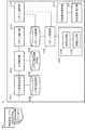
- FIG. 1 is a functional block diagram showing a functional configuration of the failure analysis apparatus 1 according to the first embodiment of the present invention.
- the failure analysis apparatus 1 includes a log element extraction unit 101, a log integration unit 102, a pattern extraction unit 103, a pattern storage unit 104, a pattern conversion unit 105, a pattern comparison unit 106, and a cause location presentation.
- Unit 107 the failure analysis apparatus 1 includes a log element extraction unit 101, a log integration unit 102, a pattern extraction unit 103, a pattern storage unit 104, a pattern conversion unit 105, a pattern comparison unit 106, and a cause location presentation.
- Unit 107 is a log element extraction unit 101, a log integration unit 102, a pattern extraction unit 103, a pattern storage unit 104, a pattern conversion unit 105, a pattern comparison unit 106, and a cause location presentation.
- the failure analysis apparatus 1 is configured to be able to collect various log information output from the information processing system 90.
- the information processing system 90 is a system to be analyzed for a failure, and may be configured by one or more computer devices (nodes) connected by a network such as a LAN (Local Area Network).
- the failure analysis apparatus 1 may be able to collect various log information output from the information processing system 90 by being connected to the information processing system 90 via a network.
- the failure analysis apparatus 1 can collect various types of log information output from the information processing system 90 by being realized by the same computer apparatus as any of the nodes constituting the information processing system 90. Also good.
- the failure analysis apparatus 1 can collect various log information by being connected to a storage device in which various log information output from the information processing system 90 is stored directly or by copying or the like. Good.
- the log information may be output as a log file by, for example, a component of the information processing system 90 (hereinafter also referred to as a system component).
- the system component may be, for example, a node that configures the information processing system 90, a software component, or the like.
- the log information output from such system components includes a system log file output by the node operating system, a log file representing an access history or a processing history output by the web server application or the database server application, etc. There is.
- the failure analysis apparatus 1 includes a CPU (Central Processing Unit) 1001, a RAM (Random Access Memory) 1002, a ROM (Read Only Memory) 1003, a storage device 1004 such as a hard disk, It can be configured by a computer device including a network interface 1005, an input device 1006, and an output device 1007.
- the log element extraction unit 101 includes a network interface 1005, an input device 1006, and a CPU 1001 that writes a computer program and various data stored in the ROM 1003 and the storage device 1004 to the RAM 1002 and executes them.
- the log integration unit 102, the pattern extraction unit 103, the pattern conversion unit 105, and the pattern comparison unit 106 write the CPU 1001 and various data stored in the ROM 1003 and the storage device 1004 to the RAM 1002, and execute them.
- the pattern storage unit 104 includes a storage device 1004.
- the cause location presenting unit 107 includes an output device 1007 and a CPU 1001 that writes a computer program and various data stored in the ROM 1003 and the storage device 1004 to the RAM 1002 and executes them. Note that the hardware configuration of the failure analysis apparatus 1 and each functional block thereof is not limited to the above-described configuration.
- the log element extraction unit 101 extracts elements (log elements) constituting log information from one or more pieces of log information output by the information processing system 90.
- the log element may be information representing a date included in a log record constituting the log information, information representing a node name, an application name, or the like. Further, the log element to be extracted may be determined in advance.
- the log integration unit 102 adds related system component information (system component information) to each log element extracted by the log element extraction unit 101. Then, the log integration unit 102 integrates the log elements to which the related system component information is added, and generates integrated log information. For example, the log integration unit 102 may add, to each log element, information representing a system component that has output log information from which the log element is extracted. Further, for example, the log integration unit 102 may generate the integrated log information by arranging the log elements to which the system component information is added in time series. In this case, the log integration unit 102 may integrate each log element according to the date and time associated with each log element in the source log information.
- system component information system component information
- the pattern extraction unit 103 extracts information patterns including system component information from the integrated log information generated by the log integration unit 102.
- a known pattern enumeration algorithm such as apriori, prefixspan, LCM (Linear time Closed itemset Miner) may be employed.
- the pattern storage unit 104 stores a pattern during the comparison target period (hereinafter also referred to as a comparison target pattern).
- the comparison target period may be a period during which the information processing system 90 is known to be operating normally, for example.
- the pattern storage unit 104 performs log element extraction unit 101, log integration unit 102, and pattern extraction for various types of log information output from the information processing system 90 during such a comparison target period.
- a pattern extracted by performing a series of processes by the unit 103 is stored as a comparison target pattern.
- the pattern storage unit 104 may store, as a comparison target pattern, a pattern that satisfies a predetermined frequent appearance among the patterns extracted as described above.
- the pattern conversion unit 105 operates when the pattern in the analysis target period (hereinafter also referred to as the analysis target pattern) includes system component information that is not included in the comparison target pattern.
- system component information that is included in the analysis target pattern and not included in the comparison target pattern is also referred to as conversion target system component information.
- the analysis target period may be, for example, a period in which a failure has occurred in the information processing system 90.
- the pattern conversion unit 105 performs a series of logs by the log element extraction unit 101, the log integration unit 102, and the pattern extraction unit 103 on various log information output from the information processing system 90 during such an analysis target period. A pattern extracted by the processing is acquired as an analysis target pattern.
- the pattern conversion unit 105 identifies system component information that is included in the comparison target pattern and is similar to the conversion target system component. Then, the pattern conversion unit 105 performs conversion between system component element information to be converted and similar system component information in either the comparison target pattern or the analysis target pattern.
- the pattern conversion unit 105 may convert a “similar system component information” into “a conversion target system component information” in the comparison target pattern as a comparison target pattern.
- the pattern conversion unit 105 may convert the “conversion target system component information” into “similar system component information” in the analysis target pattern as the analysis target pattern.
- the pattern comparison unit 106 compares the analysis target pattern and the comparison target pattern after the conversion processing by the pattern conversion unit 105, and detects a difference. For example, the pattern comparison unit 106 searches for a partial match between the analysis target pattern after the conversion process and the comparison target pattern. Then, the pattern comparison unit 106 may detect an unmatched portion as a difference in the analysis target pattern and the comparison target pattern that partially match.
- the cause location presenting unit 107 presents system component information indicating the difference detected by the pattern comparison unit 106 as the cause of the failure.
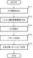
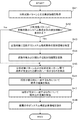
- FIG. 3 shows an operation in which the failure analysis apparatus 1 extracts a comparison target pattern and stores it in the pattern storage unit 104.
- the failure analysis apparatus 1 receives information instructing the start of generation of the comparison target pattern from the input device 1006 or another functional block (not shown) during the comparison target period, the failure analysis apparatus 1 performs pattern extraction on predetermined log information. The operation may be started. Alternatively, the failure analysis apparatus 1 may start the pattern extraction operation when receiving log information output during the comparison target period from another functional block. Alternatively, the failure analysis apparatus 1 may start the pattern extraction operation when detecting update of predetermined log information during the comparison target period. Further, the failure analysis apparatus 1 may execute the pattern extraction operation on the target log information in the range specified as the comparison target period.
- the log element extraction unit 101 extracts log elements from various target log information (step S11).
- the log integration unit 102 adds related system component information to each log element extracted in step S11 (step S12).
- the log integration unit 102 integrates the log elements to which the system component information is added in step S12, and generates integrated log information (step S13).
- the pattern extraction unit 103 extracts a pattern of information including system component information from the integrated log information generated in step S13 (step S14).
- the pattern storage unit 104 stores the pattern extracted in step S14 as a comparison target pattern (step S15).
- the failure analysis apparatus 1 finishes the comparison target pattern extraction operation.
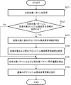
- FIG. 4 shows an operation in which the failure analysis apparatus 1 analyzes a failure in the analysis target period.
- the failure analysis apparatus 1 may start a failure analysis operation for predetermined log information.
- the failure analysis apparatus 1 may start the failure analysis operation when receiving log information output during the analysis target period from another functional block.
- the failure analysis apparatus 1 may start a failure analysis operation for predetermined log information.
- the failure analysis apparatus 1 may execute a failure analysis operation for a range specified as the analysis target period in the target log information.
- the failure analysis apparatus 1 acquires an analysis target pattern (step S21). Specifically, the log element extraction unit 101, the log integration unit 102, and the pattern extraction unit 103 are illustrated in FIG. 3 for various log information output from the information processing system 90 during the analysis target period. Steps S11 to S14 may be executed.
- the pattern conversion unit 105 determines whether or not the analysis target pattern acquired in step S21 includes system component information that is not included in the comparison target pattern stored in the pattern storage unit 104 ( Step S22).
- the operation of the failure analysis apparatus 1 proceeds to step S25.
- the pattern conversion unit 105 sets the system component information as a conversion target and is included in the comparison target pattern as a conversion target. Similar system component information is specified (step S23).
- the pattern conversion unit 105 performs conversion between the system component element information to be converted and similar system component information in either the analysis target pattern or the comparison target pattern (step S24).
- the pattern comparison unit 106 detects the difference by comparing the analysis target pattern and the comparison target pattern (step S25).
- the cause location presenting unit 107 presents the system component information related to the difference detected in step S25 as the cause location of the failure (step S26).
- the failure analysis apparatus 1 ends the failure analysis operation.
- the failure analysis apparatus can present information that can more accurately identify the cause of a failure that has not occurred in the past, even in an information processing system whose configuration changes. .
- the log element extraction unit extracts the log element from various log information output from the information processing system during the comparison target period, and the log integration unit performs a system related to the extracted log element.
- the integrated log information is generated by adding the component element information and integrating them.
- the pattern extraction unit extracts the comparison target pattern from the integrated log information and stores it in the pattern storage unit. Then, from various log information output from the information processing system during the analysis target period, the log element extraction unit extracts the log element, and the log integration unit relates to the extracted log element with related system components. Integrated log information is generated by adding information and integrating. Furthermore, the pattern extraction unit extracts the analysis target pattern from the integrated log information.
- the pattern conversion unit When the analysis target pattern includes conversion target system component information that is not included in the comparison target pattern, the pattern conversion unit identifies system configuration element information that is included in the comparison target pattern and is similar to the conversion target. To do. Furthermore, the pattern conversion unit performs conversion between the system component to be converted and the similar system components in either the comparison target pattern or the analysis target pattern. Furthermore, the pattern comparison unit compares the analysis target pattern after the conversion process with the comparison target pattern to detect a difference, and the cause location presenting unit presents system component information indicated by the detected difference.
- the failure analysis apparatus can cope with a failure that has not occurred in the past after the configuration of the information processing system has changed. This is because, by performing the above-described conversion, the pattern conversion unit increases the possibility of finding a comparison target pattern that partially matches the analysis target pattern at the time of failure from the comparison target pattern accumulated before the configuration change. Because. In such a case, the failure analysis apparatus according to the first embodiment of the present invention provides system component element information indicating a difference that the analysis target pattern does not match the comparison target pattern that partially matches, It can be presented as the cause of failure. As a result, the failure analysis apparatus according to the first embodiment of the present invention is a cause of a failure that has not occurred in the past, even when the information processing system is complicated and frequently changes in configuration. It is possible to output system component information that may have a location.
- FIG. 5 shows a functional block diagram showing a functional configuration of the failure analysis apparatus 2 according to the second embodiment of the present invention.
- the failure analysis apparatus 2 is different from the failure analysis apparatus 1 according to the first embodiment of the present invention in that a log element extraction unit 101, a log integration unit 102, a pattern extraction unit 103, a pattern storage unit 104, Instead of the pattern conversion unit 105, the pattern comparison unit 106, and the cause location presentation unit 107, a log element extraction unit 201, a log integration unit 202, a pattern extraction unit 203, a pattern storage unit 204, a pattern conversion unit 205, a pattern comparison unit 206 and a cause location presentation unit 207, and further includes a log format storage unit 208, a system component storage unit 209, and a pattern totaling unit 210.
- the pattern comparison unit 206 includes an order comparison unit 216 and a numerical value comparison unit 226.
- the pattern totaling unit 210 constitutes a part of an embodiment of the pattern extraction unit, the pattern pattern extraction
- the failure analysis apparatus 2 can be configured by a computer apparatus having the hardware configuration described with reference to FIG.
- the log format storage unit 208 and the system component storage unit 209 are configured by the storage device 1004.
- the pattern totaling unit 210 is constituted by a CPU 1001 that writes a computer program and various data stored in the ROM 1003 and the storage device 1004 to the RAM 1002 and executes them.
- the hardware configuration of the failure analysis device 2 and its functional blocks is not limited to the above-described configuration.
- the failure analysis device 2 is configured to be able to collect various log information output from the information processing system 90, similarly to the failure analysis device 1 according to the first embodiment of the present invention.
- the log information may be output as a log file by a node or a software component as a system component of the information processing system 90, for example.
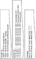
- An example of log information collected by the failure analysis apparatus 2 is shown in FIG. In FIG. 6, for example, “mysqld.log” is a log file having one or more log records each composed of log elements of “date”, “time”, and “message body”.
- “Access.log” is a log file having one or more lines of log records composed of log elements of “network address”, “date / time”, and “message body”.
- the log format storage unit 208 stores the format of information included in the log information.
- the format of information included in log information is also referred to as a log format.
- the log format may include, for example, information indicating a log type, and format information including a log element and a set of regular expressions thereof.
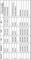
- An example of such a log format is shown in FIG. In FIG. 7, for example, in the first line, the format information of the log type “syslog” is a regular expression corresponding to each log element such as “date and time”, “node name”, “process name”, and “message”. Is represented as a set of The log format may further include information indicating the name of the corresponding log file.
- the system component storage unit 209 stores related system component information in association with related information of log information.
- the related information of the log information may be, for example, a path name in the log information storage device 1004.
- the related information of the log information may be information such as a regular expression that can identify a log record or log element included in the log information.
- each line indicates system component information.
- the system component information is associated with a path name as related information of log information.
- the system component information includes “identification information”.
- the system component information includes information representing attributes such as “component name”, “class 1”, “class 2”, and “location”.
- “component name” is the name of a node or software component.
- Category 1” is information indicating a classification of a corresponding system component such as an application, middleware, or hardware.
- Category 2 is an item obtained by further subdividing “Category 1”.
- examples of “Category 2” include a web server, an application server, and a database server.
- examples of “Category 2” include Apache, MySQL, and the like.
- “Location” is information representing a location where the corresponding system component belongs in the information processing system 90.
- the “location” of the system component whose “class 1” is a server may be a network address.
- the “location” of the system component whose “classification 1” is an application may be the name of a node in which the application is installed.
- the system component information whose identification information is “N” is also referred to as a system component “N”.
- the log element extraction unit 201 extracts a log element from the log information by referring to the log format stored in the log format storage unit 208. For example, the log element extraction unit 201 determines, from the log information, the occurrence time of the log record, output node, output node classification, output process, process ID of the output process, event ID, network address, log file name, message, etc. Extract log elements.
- the log element extraction unit 201 reads at least a part of the target log information. Then, the log element extraction unit 201 determines the log type of the log information by searching the log format storage unit 208 for a log format that matches the read information. Then, the log element extraction unit 201 may extract log elements according to the determined log type.
- the log element extraction unit 201 determines that the log format is “syslog” because it matches the log format in the first line of FIG. Then, the log element extraction unit 201 may extract log elements by referring to the format information of the matched log format based on the determined log type.
- the log element extraction unit 201 may not extract all the log elements that constitute the matched format information, and may extract a preset one of them. In that case, it is desirable that the log element set as the extraction target can identify the system component from the extracted log element or a combination thereof based on the information stored in the system component storage unit 209. .
- the log element to be extracted may be set for each log type.
- the log elements to be extracted for the log type “syslog” are defined as “date and time” and “node name”.
- the log element extraction unit 201 reads the first line of the log information “message” illustrated in FIG. 6, each log element “date and time”, “node name”, “process” included in the format information of “syslog” is displayed.
- “name” and “message” “Feb 01 09:04:01” corresponding to “date and time” and “node1” corresponding to “node name” are extracted.
- the log integration unit 202 relates each log element extracted by the log element extraction unit 201 by referring to the system component storage unit 209 based on the related information of the log information that is the extraction source. Specify system component information. Then, the log integration unit 202 integrates each log element by adding at least identification information among related system component information and arranging them in time series. Specifically, the log integration unit 202 may integrate each log element according to the date and time associated with each log element in the source log information. If information representing the date and time is extracted as the log element, the log integration unit 202 may perform integration based on the log element representing the date and time. The log integration unit 202 may add attribute information to each log element in addition to the identification information of the related system component information.
- the log integration unit 202 refers to the information in the system component storage unit 209 illustrated in FIG. 8 and extracts the path name “/ var / log / message” of the log information from which these log elements are extracted. Based on the combination with “node1” which is one of the log elements, the related component “A” is specified. Therefore, the log integration unit 202 may add the identification information “A” and its attribute information to these log elements (date and time “Feb 01 09:04:01” and node name “node1”).
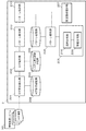
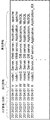
- each line indicates a log element and added system component information, and is arranged in time series.
- the log element extraction unit 201 extracts a log element representing the date and time when the log record was recorded.
- the attribute information is added to the log elements representing these dates and times together with the identification information for identifying the system components.
- the log integration unit 202 refers to the information in the system component storage unit 209 in FIG. 8 and sets the log element “2013/02/01/0209: 04: 01” in the first line in FIG.
- the log integration unit 202 adds at least identification information “V” to the log element in the first row. Further, the log integration unit 202 further adds attribute information “node1, Application, apache” of the system component “V” to the log element. Further, in this case, the log integration unit 202 determines that “node1” of the added attribute information is a system component having attribute information further from FIG. Therefore, the log integration unit 202 may further add attribute information “Server, Web server” of the system configuration element “node1” to the log element on the first line. In this way, the log integration unit 202 can recursively add the attribute information if the attribute information added to the log element includes another system component having attribute information. Good.
- the pattern extraction unit 203 extracts a pattern of system component identification information from the integrated log information generated by the log integration unit 202. Specifically, the pattern extraction unit 203 extracts the identification information while maintaining the order included in the integrated log information.
- the pattern extraction unit 203 may extract different identification information patterns after aggregating different pieces of identification information added together with similar attribute information and converting them into new identification information.
- the pattern extraction unit 203 extracts the list of identification information “VVWWWX”. Then, the pattern extraction unit 203 lists patterns that can be extracted from the list of identification information.
- a known pattern enumeration algorithm such as apriori, prefixspan, or LCM may be employed.
- the pattern extraction unit 203 may select a pattern that satisfies a predetermined condition from among patterns that can be extracted from the list of identification information.
- the predetermined condition includes the number of appearances of the pattern, the ratio of the number of appearances of the pattern to the total number of patterns, the number of identification information constituting the pattern, the average value of these values, the maximum value, the minimum value, the mode value, Or conditions based on statistical values, such as dispersion
- Such a predetermined condition may be set in advance. For example, when the ratio of patterns including other identification information “B” among patterns including certain identification information “A” is greater than 0.5, the pattern extraction unit 203 uses the identification information “A” and “B”. ” May be selected. For example, in the case of the integrated log information shown in FIG. 9, the pattern extraction unit 203 may extract the patterns “VVWW” and “WWX”.
- the pattern totaling unit 210 calculates the relative ratio of the number of appearances of the identification information of the system component included in the extracted pattern. For example, it is assumed that the pattern extraction unit 203 has extracted the identification information pattern “VVWWWWX”. In this case, the number of appearances of the identification information “V” included in this pattern is 2, the number of appearances of “W” is 3, and the number of appearances of “X” is 1. Therefore, the pattern totaling unit 210 calculates the relative ratio of the number of appearances of this pattern as 2: 3: 1.
- the pattern totaling unit 210 may total the patterns and calculate the appearance rate of each.
- the appearance rate is a ratio of the number of appearances of a certain pattern to the total number of appearances of a pattern including the pattern.
- the number of appearances of the pattern “A (1) F (1) G (3)” is 8, and a pattern including this pattern (for example, “A (1) F (1) G (3)” described above is used.
- L (2) H (1) "etc.) is assumed to be 10 times in total.
- the appearance rate of the pattern “A (1) F (1) G (3)” is calculated as 0.8.
- the appearance rate of such a pattern is calculated as 1.
- FIG. 10 shows an example of the patterns totaled by the pattern totaling unit 210 in this way.
- each pattern is given an identification number for explanation.
- a pattern having an identification number n is also referred to as a pattern n.
- the pattern 1 includes identification information “A”, “F”, “G”, and “K”, the relative ratio is 1: 1: 3: 1, and the appearance rate is 0.8. It is.
- the pattern storage unit 204 stores the comparison target patterns and the tabulation information tabulated by the pattern tabulation unit 210 for the comparison target patterns.
- the pattern conversion unit 205 When the analysis target pattern includes identification information of a system component that is not included in the comparison target pattern, the pattern conversion unit 205 operates using the identification information of the system component as a conversion target. Specifically, the pattern conversion unit 205 refers to the system component storage unit 209, and adds attribute information that satisfies a predetermined similarity condition to the attribute information included in the system component indicated by the identification information to be converted. The system component which has is searched. Then, the pattern conversion unit 205 is a system component having attribute information satisfying such a predetermined similarity condition, and the system component that is similar to the conversion target is identified with the identification information of the system component included in the comparison target pattern. It is specified as identification information.
- the predetermined similarity condition for example, a condition that attribute values other than “location” are the same may be cited.
- the predetermined similarity condition may be another condition based on attribute information and a combination thereof.
- the pattern conversion unit 205 performs conversion between the identification information of the system configuration element to be converted and the identification information of the system configuration element similar to the conversion target in either the comparison target pattern or the analysis target pattern.
- the pattern conversion unit 205 may perform conversion on the comparison target pattern or may perform conversion on the analysis target pattern, similarly to the pattern conversion unit 105 in the first embodiment of the present invention. That is, the pattern conversion unit 205 may convert identification information of similar system components in the comparison target pattern into identification information of system components to be converted. Alternatively, the pattern conversion unit 205 may convert the identification information of the system component to be converted into the identification information of a similar system component in the analysis target pattern.
- the analysis target pattern is “AFGL” and the identification information “L” is not included in any of the comparison target patterns
- the identification information “L” is to be converted.
- the system component “K” has an attribute other than “location” with respect to the system component “L” to be converted. The values match.
- the pattern conversion unit 205 identifies a similar system component “K” with respect to the system component “L” to be converted. Therefore, the pattern conversion unit 205 converts “K” to “L” in the pattern storage unit 204 for all comparison target patterns including the identification information “K”.
- the comparison target pattern “AFGLK” is converted to “AFGL”.
- the pattern conversion unit 205 may convert the identification information “L” to be converted into similar “K” in the analysis target pattern.
- the pattern conversion unit 205 converts the analysis target pattern “AFGL” into “AFGGK”.
- the pattern conversion unit 205 may perform conversion between the identification information to be converted and each of the plurality of similar identification information. Specifically, in the case of the above example, it is assumed that system components “K” and “J” similar to the system component “L” to be converted are specified. In this case, the pattern conversion unit 205 converts “K” of each comparison target pattern including the identification information “K” into “L” and each comparison including the identification information “J” in the pattern storage unit 204. What is necessary is just to convert “J” of the target pattern into “L”. For example, the comparison target pattern “AFGLK” is converted into “AFGL”, and “AFGJ” is converted into “AFGL”.
- the pattern conversion unit 205 generates a pattern obtained by converting the identification information “L” to be converted into similar identification information “K” and a pattern converted into similar identification information “J” in the analysis target pattern. May be. That is, the pattern conversion unit 205 may convert the analysis target pattern “AFGL” into “AFGGK” and “AFGJ”.
- the pattern comparison unit 206 uses the order comparison unit 216 to detect the difference by comparing the order of the identification information of the system components constituting each of the analysis target pattern and the comparison target pattern after the conversion process. Further, the pattern comparison unit 206 uses the numerical value comparison unit 226 to compare the relative ratios of the identification information of the system component elements that constitute the analysis target pattern and the comparison target pattern after the conversion process, thereby determining the difference. To detect.
- the order comparison unit 216 sets the corresponding analysis target pattern and the comparison target pattern to be described later. To the numerical value comparison unit 226.
- the order comparison unit 216 selects a part of the corresponding analysis target pattern that does not match the order of the comparison target pattern
- the identification information is output to the cause location presentation unit 207.
- the order comparison unit 216 may compare the appearance order without considering the relative ratios of the system components included in the analysis target pattern and the comparison target pattern, respectively.
- the order comparison unit 216 includes the analysis target pattern “A (1) F (2) G (1) K (3)” and the comparison target pattern “A (1) F (2) G (3)”.
- K (3) may be determined to be completely matched without considering the relative ratio, and may be output to the numerical value comparison unit 226.
- the order comparison unit 216 also analyzes the analysis target pattern “A (1) F (2) G (1) K (3)” and the comparison target pattern “A (1) F (3) X (2) K (3). ) G (3) ”, it may be determined that part of the order“ AF ”matches without considering the relative ratio.
- the order comparison unit 216 detects that the portion that does not match in the analysis target pattern is “GK” and the portion that does not match in the comparison target pattern is “XKG”. Therefore, the order comparison unit 216 outputs “G”, “K”, and “X” to the cause location presenting unit 207 as identification information of a portion having a difference.
- the order comparison unit 216 outputs the analysis target pattern to the cause location presenting unit 207 as a newly generated pattern. May be.
- the numerical value comparison unit 226 compares the relative ratios of the analysis target patterns and the patterns in which the identification information is completely matched between the comparison target patterns. Then, the numerical comparison unit 226 outputs identification information whose relative ratio does not match to the cause location presenting unit 207.
- the numerical comparison unit 226 analyzes the analysis target pattern “A (1) F (2) G (1) K (3)” and the comparison target pattern “A (1) F (2) G (1) K (3)”. ) ”Is determined to have the same relative ratio.
- the numerical comparison unit 226 also analyzes the analysis target pattern “A (1) F (2) G (1) K (3)” and the comparison target pattern “A (1) F (2) G (3) K (3). ) ”,
- the identification information“ G ” whose relative ratio does not match is detected and output to the cause location presenting unit 207.
- the cause location presenting unit 207 presents related system component information as information representing the cause of the failure based on the identification information input from the order comparison unit 216 or the numerical comparison unit 226. At this time, the cause location presenting unit 207 may present the corresponding system component information in the order of the appearance rate of the analysis target pattern or the comparison target pattern in which the system component information is detected. The cause location presenting unit 207 may present other related system component information based on the attribute information of the system component indicated by the corresponding identification information.
- the cause location presenting unit 207 acquires the system component element information indicated by the identification information “G”, “K”, and “X” by referring to the information in the system component storage unit 209 illustrated in FIG. To do. Then, the cause location presenting unit 207 includes “Application_Z” of “Node1” based on the identification information “G”, “Application_X” of “Node2” based on the identification information “K”, and “Node1” based on the identification information “X”. “Application_Y” is presented as a possible cause of failure.
- the cause location presenting unit 207 uses, as the cause location, system components such as nodes, applications, and processes that constitute the information processing system 90 and their attribute values as system component information related to the detected difference.
- system components such as nodes, applications, and processes that constitute the information processing system 90 and their attribute values as system component information related to the detected difference.
- the storage device 1004 To the output device 1007, the storage device 1004, and the like.
- the cause location presentation unit 207 may present that no failure is detected from the log information of the analysis target period.
- the failure analysis apparatus 2 extracts a comparison target pattern and stores it in the pattern storage unit 204 is shown in FIG.
- the failure analysis apparatus 2 receives information instructing generation start of the comparison target pattern from the input device 1006 or another functional block (not shown) during the comparison target period
- the failure analysis apparatus 2 targets log information determined in advance as a target.
- the pattern extraction operation may be started.
- the failure analysis device 2 may start the pattern extraction operation when log information output during the comparison target period is received from another functional block.
- the failure analysis apparatus 2 may start the pattern extraction operation when it detects an update of log information that has been set as a target in advance during the comparison target period.
- the failure analysis apparatus 2 may execute the pattern extraction operation on the target log information in the range designated as the comparison target period.
- the log element extraction unit 201 reads out various log information output from the information processing system 90 (step S31).
- the log element extraction unit 201 may read a part of each piece of log information (for example, one line or a plurality of lines) and repeat the subsequent processing, or may read all the log information collectively.
- the log element extraction unit 201 determines the type of log information by searching the log format storage unit 208 for a format that matches the log information read in step S31 (step S32). For example, when the information is read from the log file “message” illustrated in FIG. 6, the log element extraction unit 201 reads the information as if it matches the format of the first line of the information in the log format storage unit 208 illustrated in FIG. 7. It is determined that the log type of the log information is “syslog”.
- the log element extraction unit 201 extracts log elements based on the log type determined in step S32 (step S33). For example, the log element extraction unit 201 may extract a log element that is determined in advance to be extracted for the determined log type.
- the log integration unit 202 adds at least identification information of a system component related to the log element to each log element extracted in step S33 (step S34). At this time, as described above, the log integration unit 202 may further add attribute information of related system components to each log element.
- the log integration unit 202 integrates the log elements to which at least the identification information of the system components is added in step S34, and generates integrated log information (step S35).
- the pattern extraction unit 203 extracts the identification information pattern of the system component from the integrated log information generated in step S35 (step S36). At this time, as described above, the pattern extraction unit 203 may extract the identification information pattern after aggregating different identification information added together with attribute information similar to each other and converting it to new identification information. .
- the pattern totaling unit 210 calculates the relative ratio of the identification information included in the pattern extracted in step S36 and the pattern appearance rate (step S37).
- the pattern storage unit 204 stores the pattern extracted in step S36 as a comparison target pattern together with total information indicating the relative ratio and appearance rate calculated in step S37 (step S38).
- the failure analysis apparatus 2 finishes the comparison target pattern extraction operation.
- FIG. 12 shows an operation in which the failure analyzer 2 analyzes a failure in the analysis target period.
- the failure analysis device 2 may start the failure analysis operation with respect to the log information determined in advance. Good.
- the failure analysis device 2 may start a failure analysis operation when receiving log information output during the analysis target period from another functional block.
- the failure analysis apparatus 2 may start a failure analysis operation for log information that is determined in advance. Further, the failure analysis apparatus 2 may execute a failure analysis operation for a range specified as the analysis target period in the target log information.
- the failure analysis apparatus 2 acquires the analysis target pattern and its total information (step S41). Specifically, the log element extraction unit 201, the log integration unit 202, the pattern extraction unit 203, and the pattern aggregation unit 210 target various log information output from the information processing system 90 during the analysis target period. Steps S31 to S37 shown in FIG. 11 may be executed.
- the pattern conversion unit 205 determines whether or not the analysis target pattern includes identification information of a system component that is not included in the comparison target pattern (step S42).
- step S45 when the analysis target pattern does not include identification information that is not included in the comparison target pattern, the operation of the failure analysis apparatus 2 proceeds to step S45.
- the pattern conversion unit 205 converts the identification information included in the pattern stored in the pattern storage unit 204 as a conversion target.
- Identification information of a system component similar to the target is specified (step S43).
- the pattern comparison unit 206 identifies the identification information of the system component having attribute information satisfying a predetermined similarity condition with respect to the attribute information of the system component indicated by the identification information to be converted. Identify as information.
- the pattern conversion unit 205 performs conversion between identification information to be converted and similar identification information in either the analysis target pattern or the comparison target pattern (step S44).
- the order comparison unit 216 detects a comparison target pattern in which the order of the identification information completely matches the analysis target pattern and a comparison target pattern in which a part of the order matches (step S45).
- the order comparison unit 216 detects identification information whose order does not match between the comparison target pattern and the analysis target pattern whose part of the order detected in step S45 matches (step S46).
- the numerical value comparison unit 226 detects identification information in which the relative ratio does not match between the comparison target pattern and the analysis target pattern in which the order detected in step S45 completely matches (step S47).
- the cause location presenting unit 207 presents information related to the system component indicated by the identification information detected in step S46 or S47 as the cause location of the failure (step S48). For example, as described above, the cause location presenting unit 207 displays various attribute values such as the name and location of the system configuration element indicated by the detected identification information and the attribute values of other system configuration elements indicated by the attribute value. May be presented.
- the failure analyzer 2 finishes its operation.
- the failure analysis apparatus 2 can present information that can more accurately identify the cause of a failure that has not occurred in the past, even in an information processing system whose configuration changes. it can.
- the log element extraction unit extracts log elements that can identify related system components based on the format stored in the log format storage unit. Then, the log integration unit generates the integrated log information by adding at least the identification information and integrating the extracted log elements by referring to the system component storage unit and specifying the related system components. Because. Furthermore, the pattern extraction unit extracts the identification information pattern of the system component included in the integrated log information, and the pattern aggregation unit calculates the relative ratio of the identification information included in the pattern.
- the pattern conversion unit refers to the system component storage unit when the analysis target pattern includes identification information of a system component that is not included in the comparison target pattern.
- the identification information of the system configuration element similar to the system configuration element indicated by the identification information of the conversion target is identified using such identification information as the conversion target, and between the identification information of the conversion target and the similar identification information This is because conversion is performed.
- the order comparison unit detects, as a difference, identification information that does not match the order between the analysis target pattern and the comparison target pattern that match part of the order of the identification information.
- the numerical comparison unit detects, as a difference, identification information whose relative ratio does not match between the analysis target pattern and the comparison target pattern in which the order of the identification information completely matches.
- the cause location presenting unit presents information related to the system component indicated by the identification information detected as the difference as the cause location of the failure.
- the failure analysis apparatus performs conversion between the identification information included in the analysis target pattern and the identification information included in the comparison target pattern and similar to the conversion target.
- the failure analysis apparatus does not need to add or change the comparison target pattern every time the configuration of the information processing system changes, and part or all of the identification information with respect to the analysis target pattern.
- the possibility that a pattern to be compared with the same order can be detected is increased.
- the failure analysis apparatus can accurately detect the difference between the analysis target pattern and the comparison target pattern in which the order of part or all of the identification information matches.
- the failure analysis apparatus according to the present embodiment can present information related to the system component indicated by the detected difference as information that can identify the cause of the failure.
- the failure analysis apparatus detects identification information in which the relative ratio does not match between the analysis target pattern in which the order of the identification information completely matches and the comparison target pattern.
- the failure analysis apparatus presents information that can identify the cause of a failure in which a normal message is output, but a failure in which an abnormality is recognized in the number of outputs. Can do.
- FIG. 13 shows a functional block diagram showing a functional configuration of the failure analysis apparatus 3 according to the third embodiment of the present invention.
- the failure analysis apparatus 3 includes a cause location presentation unit 307 instead of the cause location presentation unit 207 with respect to the failure analysis apparatus 2 according to the second embodiment of the present invention.
- the point provided with the part 311 is different.
- the cause location totalization part 311 comprises a part of one Embodiment of the cause location presentation part which concerns on this invention.
- the failure analysis apparatus 3 can be configured by a computer apparatus having the hardware configuration described with reference to FIG.
- the cause location totalization unit 311 includes a CPU 1001 that writes a computer program and various data stored in the ROM 1003 and the storage device 1004 to the RAM 1002 and executes them.
- the hardware configuration of the failure analysis device 3 and its functional blocks is not limited to the above-described configuration.
- the cause location totalization unit 311 refers to the system component storage unit 209 and totals the attribute values of the system component information indicated by the identification information detected by the order comparison unit 216 and the numerical comparison unit 226.
- the value of the attribute “location” or the value of the attribute “classification 2” may be aggregated for the corresponding system component information.
- the cause location presenting unit 307 presents the system component information indicated by the identification information input from the order comparison unit 216 and the numerical value comparison unit 226 based on the aggregation result by the cause location aggregation unit 311. For example, the cause location presenting unit 307 may present the corresponding system component information in order from the largest number of predetermined attribute values.
- the identification information input from the order comparison unit 216 and the numerical comparison unit 226 is “X”, “G”, and “K”.
- the system component “X” is “Application_Y” of “Node1”
- the system component “G” is “Application_Z of“ Node1 ”.
- the system component “K” is “Application_X” of “Node2”.
- the cause location totalization unit 311 counts that the attribute “location” has two Node1s and one Node2.
- the cause location presenting unit 307 presents system component information related to “X” and “G” of Node 1 having a large number of aggregations for the attribute “location”, and then a system relating to “K” having Node 2 having the largest number of aggregations.
- the component information may be presented next.
- the presentation order for the system components “X” and “G” is parallel.
- the cause location presenting unit 307 may determine the presentation order in consideration of the result of counting other attribute information.
- the attribute values of the other attributes “classification 2” are “Application_Y” and “Application_Z”. Parallel.
- the cause location presenting unit 307 may present system component element information having the same attribute information tabulation result in a random order or a parallel order.
- the presentation order may be a display order or a print order, or may be an order such as the size of an output character or the size of a display area.
- the presentation order may be an order determined so as to be able to express the order of the possibility of being the cause of the failure.
- the operation of the failure analysis apparatus 3 configured as described above will be described with reference to FIG.
- the comparison target pattern extraction operation of the failure analysis apparatus 3 is the same as the comparison target pattern extraction operation of the failure analysis apparatus 2 according to the second embodiment of the present invention described with reference to FIG. The description in the embodiment is omitted.
- FIG. 14 shows the cause location presentation operation of the failure analysis apparatus 3 in step S48.
- the cause location totalizing unit 311 refers to the system component storage unit 209 to total the attribute information included in the system component information indicated by the differences detected by the order comparison unit 216 and the numerical value comparison unit 226 (step) S51).
- the cause location presenting unit 307 presents the system component information indicated by the difference in the order of presentation based on the counting result (step S52).
- the failure analysis device 3 finishes its operation.
- the failure analysis apparatus 3 presents in order from the more likely information as the cause of a failure that has not occurred in the past, even in an information processing system whose configuration changes. Can do.
- the reason is that the cause point totaling unit totals the attribute information of the system component information detected as a difference, and presents the system component information in the presentation order based on the total result.
- the failure analysis apparatus can further save labor and increase the efficiency of the work of the user who analyzes the information presented as the cause.
- FIG. 15 shows a functional block diagram showing a functional configuration of the failure analysis apparatus 4 according to the fourth embodiment of the present invention.
- the failure analysis apparatus 4 in addition to the same functional blocks as the failure analysis apparatus 2 according to the second embodiment of the present invention, the failure analysis apparatus 4 further includes a form element storage unit 412 and a form learning unit 413. The point is different.
- the failure analysis apparatus 4 can be configured by a computer apparatus having the hardware configuration described with reference to FIG.
- the format element storage unit 412 includes the storage device 1004.
- the format learning unit 413 includes a CPU 1001 that writes a computer program and various data stored in the ROM 1003 and the storage device 1004 to the RAM 1002 and executes them.
- the hardware configuration of the failure analysis device 4 and its functional blocks is not limited to the above-described configuration.
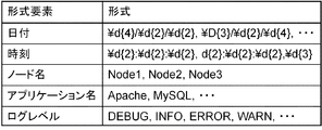
- the format element storage unit 412 stores format element information indicating the format of log elements that can constitute log information.
- log elements that can constitute log information include “date”, “time”, “node name”, “network address”, “application name”, “process name”, “log level”, and “message body”.
- An example of the format element information is shown in FIG. In FIG. 16, the first line is a regular expression “ ⁇ d ⁇ 4 ⁇ / ⁇ d ⁇ 2 ⁇ / ⁇ d ⁇ 2 ⁇ ” or “ ⁇ D ⁇ as the format of the log element“ date ”that can constitute the log information. 3 ⁇ / ⁇ d ⁇ 2 ⁇ / ⁇ d ⁇ 4 ⁇ "and so on.
- the third line in FIG. 16 indicates that any of the character strings “Node1”, “Node2”, “Node3”, etc. can be matched as the format of the log element “Node” that can constitute the log information. ing.
- the format learning unit 413 refers to the format element storage unit 412 for log information whose format is not stored in the log format storage unit 208, thereby learning the format of log elements constituting the log information. Then, the format learning unit 413 stores the learned log information format in the log format storage unit 208.
- the format learning unit 413 reads the target log information and searches for one that matches the format element information stored in the format element storage unit 412. Then, the log format storage unit 208 may store the read log information replaced with the matched format element information. At this time, the format learning unit 413 may replace the corresponding log element with the matched regular expression in the read log information for the format element information represented by the regular expression. Also, the format learning unit 413 replaces the corresponding log element with the regular expression “ ⁇ w +?” Or the like representing an arbitrary word in the read log information for the format element information represented by word candidates. Also good. For example, assume that the read log information is “2013/02/01/0216: 00: 01 DEBUG connection failure”.
- the format learning unit 413 searches the matching log element format with reference to the format element information of FIG. 16, and the read log information is “date”, “time”, “log level”, “message”. It is determined that it matches each log element format. As in this example, the format learning unit 413 may determine that an element that does not match any format element information is a log element “message”. In this case, the format learning unit 413 may store new log format information in the log format storage unit 208 as shown in FIG.
- the failure analysis device 4 may start the format learning operation by receiving information instructing the start of learning of the format of the log information from the input device 1006 or another functional block (not shown).
- the failure analysis device 4 may target, for example, log information stored in a predetermined storage location that is not stored in the log format storage unit 208.
- the failure analysis device 4 may start the format learning operation when receiving the log information of the format learning target from another functional block.
- the failure analysis device 4 performs the format learning operation when log information not stored in the log format storage unit 208 is detected when the log element extraction unit 201 executes log element extraction processing. You may start.
- the format learning unit 413 reads at least a part of information from the target log information (step S61).
- the format learning unit 413 searches the format element storage unit 412 for format element information that matches the information read in step S61 (step S62).
- the format learning unit 413 replaces the information read in step S61 based on the format element information matched in step S62 (step S63).
- the format learning unit 413 adds the information generated in step S63 as format information to the log format storage unit 208 (step S64).
- the failure analysis device 4 ends the formal learning operation.
- the pattern extraction operation and the failure analysis operation of the failure analysis device 4 are the same as those of the failure analysis device 2 according to the second embodiment of the present invention described with reference to FIGS. The description in the form is omitted.
- the failure analysis apparatus 4 according to the fourth exemplary embodiment of the present invention has occurred in the past even when log information in an unknown format is output due to a configuration change in an information processing system whose configuration changes. It is possible to present information that can identify the cause of no failure.
- the format element storage unit stores the format of log elements that can constitute the log information
- the format learning unit searches for the format element information that matches the log information of the unknown format. This is because information is generated and stored in the log format storage unit.
- the failure analysis apparatus can extract log elements from such log information even if the format of the log information to be compared or analyzed frequently changes due to a change in configuration, The same effects as those of the second embodiment of the present invention can be achieved.
- system components in the present invention may be other elements as long as they constitute an information processing system that is a target of failure analysis.
- the pattern extraction unit has been described mainly with respect to an example of extracting a pattern of identification information of a system component.
- the pattern extraction unit may extract a pattern including not only system component identification information but also log elements and added attribute information.
- the pattern comparison unit first performs a comparison in consideration of the order of the system components, and the analysis target pattern and the comparison target pattern in which the order is completely matched. It was explained as a comparison of the relative ratios.
- the pattern comparison unit may compare the analysis target pattern and the comparison target pattern as a set of system component information that does not consider the order and the number of appearances.
- the pattern comparison unit may output, to the cause location presenting unit, system component element information that is an element of a mismatched part with respect to an analysis target pattern and a comparison target pattern that match some of the elements of the set.
- the pattern comparison unit may output system component element information, which is an element whose relative ratio does not match, to the cause location presenting unit for the analysis target pattern and the comparison target pattern in which all elements of the set match.
- the pattern comparison unit is described as comparing the relative ratio of the number of appearances of the analysis target pattern and the comparison target pattern that are completely in the same order. did.
- the pattern comparison unit is not limited to the relative ratio of the number of appearances, and may detect a difference based on other information that can be calculated from the number of appearances.
- the cause location presenting unit is You may make it present the system component information before conversion.
- each functional block of the failure analysis device is realized by a CPU that executes a computer program stored in a storage device or ROM.
- part, all, or a combination of each functional block of the failure analysis apparatus may be realized by dedicated hardware.
- the functional blocks of the failure analysis device may be realized by being distributed among a plurality of devices.
- the operation of the failure analysis apparatus described with reference to each flowchart is stored as a computer program of the present invention in a storage device (storage medium) of the computer device, and the computer The program may be read and executed by the CPU.
- the present invention is constituted by the code of the computer program or a storage medium.
- a log element extraction unit that extracts elements (log elements) constituting the log information from one or more pieces of log information output by the information processing system, and the information processing for each log element By adding system component element information representing system component elements (system component elements) that are related to the log element, the log elements to which the system component element information is added are integrated and integrated.
- a log integration unit that generates log information
- a pattern extraction unit that extracts a pattern of information including the system component information from the integrated log information
- the system configuration element not included in the comparison target pattern is included in the storage unit and the pattern (analysis target pattern) during the analysis target period
- information system component information to be converted
- either the comparison target pattern or the analysis target pattern is included in the system component information to be converted and the comparison target pattern.
- a pattern conversion unit that performs conversion between system component information similar to the conversion target, and a pattern comparison unit that detects a difference by comparing the analysis target pattern and the comparison target pattern after the conversion processing by the pattern conversion unit; And a cause location presenting unit that presents the system component information indicated by the difference detected by the pattern comparison unit as a cause of the failure.
- the said pattern comparison part detects a difference by comparing the order of the said system component element information each included in the said analysis object pattern and the said comparison object pattern, The failure of Additional remark 1 characterized by the above-mentioned Analysis equipment.
- the said pattern comparison part detects a difference by comparing the information regarding the frequency
- the system further includes a system component storage unit that stores the related system component information in association with the related information of each log information, and the log integration unit The failure analysis according to any one of appendix 1 to appendix 3, wherein the related system component information is identified and added based on the relevant information of the log information from which the log element is extracted apparatus.
- the said system component storage part contains the identification information of the said system component in the said system component information, and memorize
- the said log integration part is a system configuration relevant to each said log element
- the said system component storage part contains the attribute information showing the attribute of the said system component in the said system component information, and the said pattern conversion part refers to the said system component storage part
- the system component having attribute information satisfying a predetermined similarity condition with respect to the attribute information of the system component to be converted is identified as the similar system component information.
- the failure analyzer according to appendix 5.
- the log information further includes a log format storage unit that stores a format of log elements constituting the log information, and the log element extraction unit refers to the log format storage unit, thereby 7.
- the failure analysis apparatus according to any one of appendix 1 to appendix 6, wherein the log element is extracted from information.
- the failure analysis apparatus according to appendix 7, further comprising: a format learning unit that learns the format of log elements constituting the log information by referring to and stores the format in the log format storage unit.
- the cause location presenting unit for the system component information indicated by the difference detected by the pattern comparison unit, based on the analysis pattern or the appearance rate of the comparison target pattern in which the difference is detected, 9.
- the failure analysis device according to any one of appendix 1 to appendix 8, wherein the system component information is presented as a fault cause location.
- the said cause location presentation part presents this system component information as a cause location of a failure based on the total result of the attribute information which the said system component information which the difference detected by the said pattern comparison part has has has
- the failure analysis apparatus according to any one of appendix 1 to appendix 9, wherein:
- Supplementary Note 11 Any one of Supplementary Note 1 to Supplementary Note 10, wherein the pattern conversion unit converts the similar system component information into the system component information to be converted in the comparison target pattern. Failure analysis device described in one.
- Supplementary Note 12 Any one of Supplementary Note 1 to Supplementary Note 10, wherein the pattern conversion unit converts the system component element information to be converted into the similar system component element information in the analysis target pattern. Failure analysis device described in one.
- An element (log element) constituting the log information is extracted from one or more pieces of log information output by the information processing system, and the constituent elements of the information processing system (System component element) that represents a system component related to the log element, and integrates each log element to which the system component information is added to generate integrated log information.
- the information pattern including the system component information is extracted from the integrated log information and included in the pattern (analysis target pattern) during the analysis target period and included in the pattern (comparison target pattern) during the comparison target period. If there is no system component information (conversion target system component information), the comparison target pattern and the analysis target In any of the turns, the conversion is performed between the system component information of the conversion target and the system component information included in the comparison target pattern and similar to the conversion target. After the conversion process, the analysis target pattern and the analysis target pattern Compare the comparison patterns to detect differences, A failure analysis method for presenting the system component information indicated by the detected difference as a cause of a failure.
- the log element extraction step which extracts the element (log element) which constitutes the log information from one or more log information outputted by the information processing system, and the information processing for each log element
- system component element information representing system component elements (system component elements) that are related to the log element
- the log elements to which the system component element information is added are integrated and integrated.
- a log integration step for generating log information, a pattern extraction step for extracting a pattern of information including the system component information from the integrated log information, and the log element extraction for the log information in a comparison target period The pattern extracted by executing the step, the log integration step, and the pattern extraction step.
- a pattern storage step for storing a pattern (comparison target pattern) in a pattern storage unit, and the log element extraction step, the log integration step, and the pattern extraction step are executed on the log information during the analysis target period. If the system component information not included in the comparison target pattern (conversion target system component information) is included in the extracted pattern (analysis target pattern), the comparison target pattern and the analysis In any one of the target patterns, a pattern conversion step for converting between the system component element information to be converted and system component element information included in the comparison target pattern and similar to the conversion target; and after the pattern conversion step , Comparing the analysis target pattern and the comparison target pattern A pattern comparison step of detecting a difference computer program to be executed and cause location presenting step of presenting the system configuration element information indicating the detected difference as a cause location fault in said pattern comparison step, to the computer device.
Landscapes
- Engineering & Computer Science (AREA)
- Theoretical Computer Science (AREA)
- General Engineering & Computer Science (AREA)
- Quality & Reliability (AREA)
- Physics & Mathematics (AREA)
- General Physics & Mathematics (AREA)
- Health & Medical Sciences (AREA)
- Biomedical Technology (AREA)
- Computer Hardware Design (AREA)
- Debugging And Monitoring (AREA)
Abstract
Description
本発明の第1の実施の形態に係る障害分析装置1の機能構成を示す機能ブロック図を図1に示す。図1において、障害分析装置1は、ログ要素抽出部101と、ログ統合部102と、パターン抽出部103と、パターン記憶部104と、パターン変換部105と、パターン比較部106と、原因箇所提示部107とを備える。
次に、本発明の第2の実施の形態について図面を参照して詳細に説明する。なお、本実施の形態の説明において参照する各図面において、本発明の第1の実施の形態と同一の構成および同様に動作するステップには同一の符号を付して本実施の形態における詳細な説明を省略する。
次に、本発明の第3の実施の形態について図面を参照して詳細に説明する。なお、本実施の形態の説明において参照する各図面において、本発明の第2の実施の形態と同一の構成および同様に動作するステップには同一の符号を付して本実施の形態における詳細な説明を省略する。
次に、本発明の第4の実施の形態について図面を参照して詳細に説明する。なお、本実施の形態の説明において参照する各図面において、本発明の第2の実施の形態と同一の構成および同様に動作するステップには同一の符号を付して本実施の形態における詳細な説明を省略する。
検出された差異の示す前記システム構成要素情報を障害の原因箇所として提示する、障害分析方法。
90 情報処理システム
101、201 ログ要素抽出部
102、202 ログ統合部
103、203 パターン抽出部
104、204 パターン記憶部
105、205 パターン変換部
106、206 パターン比較部
107、207、307 原因箇所提示部
208 ログ形式記憶部
209 システム構成要素記憶部
210 パターン集計部
216 順序比較部
226 数値比較部
311 原因箇所集計部
412 形式要素記憶部
413 形式学習部
1001 CPU
1002 RAM
1003 ROM
1004 記憶装置
1005 ネットワークインタフェース
1006 入力装置
1007 出力装置
Claims (10)
- 情報処理システムによって出力される1つ以上のログ情報から、前記ログ情報を構成する要素であるログ要素を抽出するログ要素抽出手段と、
前記各ログ要素に対して、前記情報処理システムの構成要素であるシステム構成要素であって該ログ要素に関連するシステム構成要素を表すシステム構成要素情報を付加し、前記システム構成要素情報が付加された各ログ要素を統合した統合ログ情報を生成するログ統合手段と、
前記統合ログ情報から、前記システム構成要素情報を含む情報のパターンを抽出するパターン抽出手段と、
分析対象となる期間である分析対象期間中の前記パターンである分析対象パターンに、パターン記憶手段に記憶されたパターンであって、比較対象となる期間である比較対象期間中の前記パターンである比較対象パターンに含まれない前記システム構成要素情報である変換対象のシステム構成要素情報が含まれている場合、前記比較対象パターンおよび前記分析対象パターンのいずれかにおいて、前記変換対象のシステム構成要素情報と、前記比較対象パターンに含まれ該変換対象のシステム構成要素情報に類似するシステム構成要素情報との間で変換を行うパターン変換手段と、
前記パターン変換手段による変換処理後に、前記分析対象パターンおよび前記比較対象パターンを比較して差異を検出するパターン比較手段と、
前記パターン比較手段によって検出された差異の示す前記システム構成要素情報を障害の原因箇所として提示する原因箇所提示手段と、
を備えることを特徴とする障害分析装置。 - 前記パターン比較手段は、前記分析対象パターンおよび前記比較対象パターンにそれぞれ含まれる前記システム構成要素情報の順序を比較することにより差異を検出することを特徴とする請求項1に記載の障害分析装置。
- 前記パターン比較手段は、前記分析対象パターンおよび前記比較対象パターンにそれぞれ含まれる前記システム構成要素情報の出現回数に関する情報を比較することにより差異を検出することを特徴とする請求項1または請求項2に記載の障害分析装置。
- 各前記ログ情報の関連情報に対応付けて、関連する前記システム構成要素情報を記憶するシステム構成要素記憶手段をさらに備え、
前記ログ統合手段は、前記各ログ要素に対して、該ログ要素の抽出元である前記ログ情報の関連情報に基づいて、関連する前記システム構成要素情報を特定して付加することを特徴とする請求項1から請求項3のいずれか1項に記載の障害分析装置。 - 前記システム構成要素記憶手段は、前記システム構成要素を識別するための識別情報を、前記システム構成要素情報に含んで記憶し、
前記ログ統合手段は、前記各ログ要素に対して、少なくとも、関連する前記システム構成要素の前記識別情報を付加して前記統合ログ情報を生成し、
前記パターン抽出手段は、前記システム構成要素の前記識別情報のパターンを抽出することを特徴とする請求項4に記載の障害分析装置。 - 前記システム構成要素記憶手段は、前記システム構成要素の属性を表す属性情報を、前記システム構成要素情報に含んで記憶し、
前記パターン変換手段は、前記システム構成要素記憶手段を参照することにより、前記変換対象のシステム構成要素情報が有する属性情報に対して所定の類似条件を満たす属性情報を有するシステム構成要素情報を、前記類似するシステム構成要素情報として特定することを特徴とする請求項4または請求項5に記載の障害分析装置。 - 前記ログ情報について、該ログ情報を構成するログ要素の形式を記憶するログ形式記憶手段をさらに備え、
前記ログ要素抽出手段は、前記ログ形式記憶手段を参照することにより、前記ログ情報から前記ログ要素を抽出することを特徴とする請求項1から請求項6のいずれか1項に記載の障害分析装置。 - 前記ログ情報を構成し得るログ要素の形式を表す形式要素情報を記憶する形式要素記憶手段と、
前記ログ形式記憶手段に形式が記憶されていないログ情報について、前記形式要素記憶手段を参照することにより該ログ情報を構成するログ要素の形式を学習して前記ログ形式記憶手段に記憶する形式学習手段と、をさらに備えることを特徴とする請求項7に記載の障害分析装置。 - 障害分析装置の障害分析方法であって、
情報処理システムによって出力される1つ以上のログ情報から、前記ログ情報を構成する要素であるログ要素を抽出し、
前記各ログ要素に対して、前記情報処理システムの構成要素であるシステム構成要素であって該ログ要素に関連するシステム構成要素を表すシステム構成要素情報を付加し、前記システム構成要素情報が付加された各ログ要素を統合した統合ログ情報を生成し、
前記統合ログ情報から、前記システム構成要素情報を含む情報のパターンを抽出し、
分析対象となる期間である分析対象期間中の前記パターンである分析対象パターンに、比較対象となる期間である比較対象期間中の前記パターンである比較対象パターンに含まれない前記システム構成要素情報である変換対象のシステム構成要素情報が含まれている場合、前記比較対象パターンおよび前記分析対象パターンのいずれかにおいて、前記変換対象のシステム構成要素情報と、前記比較対象パターンに含まれ該変換対象のシステム構成要素情報に類似するシステム構成要素情報との間で変換を行い、
変換処理後に、前記分析対象パターンおよび前記比較対象パターンを比較して差異を検出し、
検出された差異の示す前記システム構成要素情報を障害の原因箇所として提示する、障害分析方法。 - 情報処理システムによって出力される1つ以上のログ情報から、前記ログ情報を構成する要素であるログ要素を抽出するログ要素抽出ステップと、
前記各ログ要素に対して、前記情報処理システムの構成要素であるシステム構成要素であって該ログ要素に関連するシステム構成要素を表すシステム構成要素情報を付加し、前記システム構成要素情報が付加された各ログ要素を統合した統合ログ情報を生成するログ統合ステップと、
前記統合ログ情報から、前記システム構成要素情報を含む情報のパターンを抽出するパターン抽出ステップと、
比較対象となる期間である比較対象期間中の前記ログ情報に対して、前記ログ要素抽出ステップ、前記ログ統合ステップ、および、前記パターン抽出ステップが実行されることにより抽出された前記パターンである比較対象パターンを記憶させるパターン記憶ステップと、
分析対象となる期間である分析対象期間中の前記ログ情報に対して、前記ログ要素抽出ステップ、前記ログ統合ステップ、および、前記パターン抽出ステップが実行されることにより抽出されたパターンである分析対象パターンに、前記比較対象パターンに含まれない前記システム構成要素情報である変換対象のシステム構成要素情報が含まれている場合、前記比較対象パターンおよび前記分析対象パターンのいずれかにおいて、前記変換対象のシステム構成要素情報と、前記比較対象パターンに含まれ該変換対象のシステム構成要素情報に類似するシステム構成要素情報との間で変換を行うパターン変換ステップと、
前記パターン変換ステップ後に、前記分析対象パターンおよび前記比較対象パターンを比較して差異を検出するパターン比較ステップと、
前記パターン比較ステップにおいて検出された差異の示す前記システム構成要素情報を障害の原因箇所として提示する原因箇所提示ステップと、
をコンピュータ装置に実行させるコンピュータ・プログラムを記録するコンピュータで読み取り可能な記録媒体。
Priority Applications (2)
| Application Number | Priority Date | Filing Date | Title |
|---|---|---|---|
| JP2015521273A JP6233411B2 (ja) | 2013-06-03 | 2014-05-15 | 障害分析装置、障害分析方法、および、コンピュータ・プログラム |
| US14/889,906 US9612898B2 (en) | 2013-06-03 | 2014-05-15 | Fault analysis apparatus, fault analysis method, and recording medium |
Applications Claiming Priority (2)
| Application Number | Priority Date | Filing Date | Title |
|---|---|---|---|
| JP2013-116952 | 2013-06-03 | ||
| JP2013116952 | 2013-06-03 |
Publications (1)
| Publication Number | Publication Date |
|---|---|
| WO2014196129A1 true WO2014196129A1 (ja) | 2014-12-11 |
Family
ID=52007790
Family Applications (1)
| Application Number | Title | Priority Date | Filing Date |
|---|---|---|---|
| PCT/JP2014/002569 Ceased WO2014196129A1 (ja) | 2013-06-03 | 2014-05-15 | 障害分析装置、障害分析方法、および、記録媒体 |
Country Status (3)
| Country | Link |
|---|---|
| US (1) | US9612898B2 (ja) |
| JP (1) | JP6233411B2 (ja) |
| WO (1) | WO2014196129A1 (ja) |
Cited By (7)
| Publication number | Priority date | Publication date | Assignee | Title |
|---|---|---|---|---|
| JP2018041288A (ja) * | 2016-09-07 | 2018-03-15 | 富士通株式会社 | ログ管理装置及びログ管理プログラム |
| JP2018045403A (ja) * | 2016-09-14 | 2018-03-22 | 株式会社日立製作所 | 異常検知システム及び異常検知方法 |
| JP2018112867A (ja) * | 2017-01-11 | 2018-07-19 | 日本電信電話株式会社 | 照合装置、照合方法及び照合プログラム |
| JPWO2017104119A1 (ja) * | 2015-12-14 | 2018-09-27 | 日本電気株式会社 | ログ分析システム、方法およびプログラム |
| JP2019501448A (ja) * | 2015-11-18 | 2019-01-17 | エヌイーシー ラボラトリーズ アメリカ インクNEC Laboratories America, Inc. | 異種混成ログストリームにおける自動化された異常検出サービス |
| CN109885505A (zh) * | 2019-03-21 | 2019-06-14 | 浪潮商用机器有限公司 | 一种故障定位的方法、系统及相关组件 |
| US20210011832A1 (en) * | 2018-04-19 | 2021-01-14 | Nec Corporation | Log analysis system, log analysis method, and storage medium |
Families Citing this family (13)
| Publication number | Priority date | Publication date | Assignee | Title |
|---|---|---|---|---|
| JP6152788B2 (ja) * | 2013-12-02 | 2017-06-28 | 富士通株式会社 | 障害予兆検知方法、情報処理装置およびプログラム |
| JP6295857B2 (ja) * | 2014-06-27 | 2018-03-20 | 富士通株式会社 | 抽出方法、装置、及びプログラム |
| KR101594701B1 (ko) * | 2014-10-20 | 2016-02-16 | 삼성에스디에스 주식회사 | 이상 접속 검출 장치 및 방법 |
| US10069699B2 (en) * | 2015-02-26 | 2018-09-04 | Nippon Telegraph And Telephone Corporation | Monitoring device information analyzing device and method, and non-transitory storage medium storing program |
| US10140287B2 (en) * | 2015-09-09 | 2018-11-27 | International Business Machines Corporation | Scalable and accurate mining of control flow from execution logs across distributed systems |
| US10146609B1 (en) * | 2016-07-08 | 2018-12-04 | Splunk Inc. | Configuration of continuous anomaly detection service |
| EP3407273A1 (de) * | 2017-05-22 | 2018-11-28 | Siemens Aktiengesellschaft | Verfahren und anordnung zur ermittlung eines anomalen zustands eines systems |
| US11294754B2 (en) * | 2017-11-28 | 2022-04-05 | Nec Corporation | System and method for contextual event sequence analysis |
| US11514360B2 (en) * | 2019-07-12 | 2022-11-29 | EMC IP Holding Company LLC | Method and system for verifying state monitor reliability in hyper-converged infrastructure appliances |
| CN111324510B (zh) * | 2020-02-21 | 2024-04-02 | 腾讯科技(深圳)有限公司 | 日志处理方法、装置及电子设备 |
| US11221907B1 (en) * | 2021-01-26 | 2022-01-11 | Morgan Stanley Services Group Inc. | Centralized software issue triage system |
| CN115495424A (zh) * | 2021-06-18 | 2022-12-20 | 伊姆西Ip控股有限责任公司 | 数据处理的方法、电子设备和计算机程序产品 |
| US12425243B2 (en) * | 2023-03-09 | 2025-09-23 | Bank Of America Corporation | Resolving failed data interactions performed by an internet of things (IoT) device |
Citations (5)
| Publication number | Priority date | Publication date | Assignee | Title |
|---|---|---|---|---|
| JP2006146668A (ja) * | 2004-11-22 | 2006-06-08 | Ntt Data Corp | 運用管理支援装置及び運用管理支援プログラム |
| JP2011192097A (ja) * | 2010-03-16 | 2011-09-29 | Hitachi Ltd | 異常検知方法およびそれを用いた情報処理システム |
| JP2012123694A (ja) * | 2010-12-10 | 2012-06-28 | Fujitsu Ltd | 管理装置、管理方法および管理用プログラム |
| JP2012141802A (ja) * | 2010-12-28 | 2012-07-26 | Fujitsu Ltd | プログラム、情報処理装置、及び情報処理方法 |
| US20120330639A1 (en) * | 2010-05-20 | 2012-12-27 | International Business Machines Corporation | Automatic model evolution |
Family Cites Families (5)
| Publication number | Priority date | Publication date | Assignee | Title |
|---|---|---|---|---|
| EP1577783A4 (en) * | 2002-12-26 | 2008-04-16 | Fujitsu Ltd | OPERATIONAL MANAGEMENT PROCESS AND OPERATION MANAGEMENT SERVER |
| JP2006059266A (ja) | 2004-08-23 | 2006-03-02 | Fujitsu Ltd | 障害解析方法及びその装置 |
| JP4944391B2 (ja) | 2005-05-11 | 2012-05-30 | 富士通株式会社 | メッセージ異常自動判別装置、方法、及びプログラム |
| US8495429B2 (en) * | 2010-05-25 | 2013-07-23 | Microsoft Corporation | Log message anomaly detection |
| JP6295857B2 (ja) * | 2014-06-27 | 2018-03-20 | 富士通株式会社 | 抽出方法、装置、及びプログラム |
-
2014
- 2014-05-15 US US14/889,906 patent/US9612898B2/en active Active
- 2014-05-15 WO PCT/JP2014/002569 patent/WO2014196129A1/ja not_active Ceased
- 2014-05-15 JP JP2015521273A patent/JP6233411B2/ja active Active
Patent Citations (5)
| Publication number | Priority date | Publication date | Assignee | Title |
|---|---|---|---|---|
| JP2006146668A (ja) * | 2004-11-22 | 2006-06-08 | Ntt Data Corp | 運用管理支援装置及び運用管理支援プログラム |
| JP2011192097A (ja) * | 2010-03-16 | 2011-09-29 | Hitachi Ltd | 異常検知方法およびそれを用いた情報処理システム |
| US20120330639A1 (en) * | 2010-05-20 | 2012-12-27 | International Business Machines Corporation | Automatic model evolution |
| JP2012123694A (ja) * | 2010-12-10 | 2012-06-28 | Fujitsu Ltd | 管理装置、管理方法および管理用プログラム |
| JP2012141802A (ja) * | 2010-12-28 | 2012-07-26 | Fujitsu Ltd | プログラム、情報処理装置、及び情報処理方法 |
Cited By (7)
| Publication number | Priority date | Publication date | Assignee | Title |
|---|---|---|---|---|
| JP2019501448A (ja) * | 2015-11-18 | 2019-01-17 | エヌイーシー ラボラトリーズ アメリカ インクNEC Laboratories America, Inc. | 異種混成ログストリームにおける自動化された異常検出サービス |
| JPWO2017104119A1 (ja) * | 2015-12-14 | 2018-09-27 | 日本電気株式会社 | ログ分析システム、方法およびプログラム |
| JP2018041288A (ja) * | 2016-09-07 | 2018-03-15 | 富士通株式会社 | ログ管理装置及びログ管理プログラム |
| JP2018045403A (ja) * | 2016-09-14 | 2018-03-22 | 株式会社日立製作所 | 異常検知システム及び異常検知方法 |
| JP2018112867A (ja) * | 2017-01-11 | 2018-07-19 | 日本電信電話株式会社 | 照合装置、照合方法及び照合プログラム |
| US20210011832A1 (en) * | 2018-04-19 | 2021-01-14 | Nec Corporation | Log analysis system, log analysis method, and storage medium |
| CN109885505A (zh) * | 2019-03-21 | 2019-06-14 | 浪潮商用机器有限公司 | 一种故障定位的方法、系统及相关组件 |
Also Published As
| Publication number | Publication date |
|---|---|
| JP6233411B2 (ja) | 2017-11-22 |
| JPWO2014196129A1 (ja) | 2017-02-23 |
| US9612898B2 (en) | 2017-04-04 |
| US20160124792A1 (en) | 2016-05-05 |
Similar Documents
| Publication | Publication Date | Title |
|---|---|---|
| JP6233411B2 (ja) | 障害分析装置、障害分析方法、および、コンピュータ・プログラム | |
| US11734315B2 (en) | Method and system for implementing efficient classification and exploration of data | |
| CN110321371B (zh) | 日志数据异常检测方法、装置、终端及介质 | |
| US10423647B2 (en) | Descriptive datacenter state comparison | |
| US12608390B2 (en) | Method and system for implementing a log parser in a log analytics system | |
| CN107111625B (zh) | 实现数据的高效分类和探索的方法和系统 | |
| US9652318B2 (en) | System and method for automatically managing fault events of data center | |
| Xu et al. | Mining Console Logs for Large-Scale System Problem Detection. | |
| US20180075235A1 (en) | Abnormality Detection System and Abnormality Detection Method | |
| US20180234328A1 (en) | Service analyzer interface | |
| US9792388B2 (en) | Pattern extraction apparatus and control method therefor | |
| JP5521807B2 (ja) | 障害原因推定装置、障害原因推定プログラム及び障害原因推定方法 | |
| JP6741216B2 (ja) | ログ分析システム、方法およびプログラム | |
| US9311176B1 (en) | Evaluating a set of storage devices and providing recommended activities | |
| CN114138977B (zh) | 日志处理方法、装置、计算机设备和存储介质 | |
| US20170168911A1 (en) | Computer-implemented method, information processing device, and recording medium | |
| US20140006010A1 (en) | Parsing rules for data | |
| JP4997856B2 (ja) | データベース分析プログラム、データベース分析装置、データベース分析方法 | |
| KR20120052415A (ko) | 운용 관리 장치 및 운용 관리 방법 | |
| CN118819941A (zh) | 故障诊断方法、装置、设备、存储介质和程序产品 | |
| US10346450B2 (en) | Automatic datacenter state summarization | |
| CN120596301A (zh) | 运维数据异常定位方法及计算设备 | |
| JP2021135541A (ja) | モデル生成装置、モデル生成方法、及びモデル生成プログラム | |
| JPWO2007007410A1 (ja) | メッセージ解析装置、制御方法および制御プログラム | |
| Wessman | Advanced Algorithms for Classification and Anomaly Detection on Log File Data: Comparative study of different Machine Learning Approaches |
Legal Events
| Date | Code | Title | Description |
|---|---|---|---|
| 121 | Ep: the epo has been informed by wipo that ep was designated in this application |
Ref document number: 14807399 Country of ref document: EP Kind code of ref document: A1 |
|
| WWE | Wipo information: entry into national phase |
Ref document number: 14889906 Country of ref document: US |
|
| ENP | Entry into the national phase |
Ref document number: 2015521273 Country of ref document: JP Kind code of ref document: A |
|
| NENP | Non-entry into the national phase |
Ref country code: DE |
|
| 122 | Ep: pct application non-entry in european phase |
Ref document number: 14807399 Country of ref document: EP Kind code of ref document: A1 |