WO2014196116A1 - Internal combustion engine - Google Patents
Internal combustion engine Download PDFInfo
- Publication number
- WO2014196116A1 WO2014196116A1 PCT/JP2014/002106 JP2014002106W WO2014196116A1 WO 2014196116 A1 WO2014196116 A1 WO 2014196116A1 JP 2014002106 W JP2014002106 W JP 2014002106W WO 2014196116 A1 WO2014196116 A1 WO 2014196116A1
- Authority
- WO
- WIPO (PCT)
- Prior art keywords
- temperature
- purification catalyst
- exhaust purification
- fuel
- rate
- Prior art date
- Legal status (The legal status is an assumption and is not a legal conclusion. Google has not performed a legal analysis and makes no representation as to the accuracy of the status listed.)
- Ceased
Links
Images



Classifications
-
- F—MECHANICAL ENGINEERING; LIGHTING; HEATING; WEAPONS; BLASTING
- F02—COMBUSTION ENGINES; HOT-GAS OR COMBUSTION-PRODUCT ENGINE PLANTS
- F02D—CONTROLLING COMBUSTION ENGINES
- F02D41/00—Electrical control of supply of combustible mixture or its constituents
- F02D41/30—Controlling fuel injection
- F02D41/3094—Controlling fuel injection the fuel injection being effected by at least two different injectors, e.g. one in the intake manifold and one in the cylinder
-
- F—MECHANICAL ENGINEERING; LIGHTING; HEATING; WEAPONS; BLASTING
- F01—MACHINES OR ENGINES IN GENERAL; ENGINE PLANTS IN GENERAL; STEAM ENGINES
- F01N—GAS-FLOW SILENCERS OR EXHAUST APPARATUS FOR MACHINES OR ENGINES IN GENERAL; GAS-FLOW SILENCERS OR EXHAUST APPARATUS FOR INTERNAL-COMBUSTION ENGINES
- F01N3/00—Exhaust or silencing apparatus having means for purifying, rendering innocuous, or otherwise treating exhaust
- F01N3/08—Exhaust or silencing apparatus having means for purifying, rendering innocuous, or otherwise treating exhaust for rendering innocuous
- F01N3/10—Exhaust or silencing apparatus having means for purifying, rendering innocuous, or otherwise treating exhaust for rendering innocuous by thermal or catalytic conversion of noxious components of exhaust
- F01N3/24—Exhaust or silencing apparatus having means for purifying, rendering innocuous, or otherwise treating exhaust for rendering innocuous by thermal or catalytic conversion of noxious components of exhaust characterised by constructional aspects of converting apparatus
- F01N3/30—Arrangements for supply of additional air
-
- F—MECHANICAL ENGINEERING; LIGHTING; HEATING; WEAPONS; BLASTING
- F02—COMBUSTION ENGINES; HOT-GAS OR COMBUSTION-PRODUCT ENGINE PLANTS
- F02D—CONTROLLING COMBUSTION ENGINES
- F02D41/00—Electrical control of supply of combustible mixture or its constituents
- F02D41/02—Circuit arrangements for generating control signals
- F02D41/021—Introducing corrections for particular conditions exterior to the engine
- F02D41/0235—Introducing corrections for particular conditions exterior to the engine in relation with the state of the exhaust gas treating apparatus
- F02D41/024—Introducing corrections for particular conditions exterior to the engine in relation with the state of the exhaust gas treating apparatus to increase temperature of the exhaust gas treating apparatus
- F02D41/0245—Introducing corrections for particular conditions exterior to the engine in relation with the state of the exhaust gas treating apparatus to increase temperature of the exhaust gas treating apparatus by increasing temperature of the exhaust gas leaving the engine
-
- F—MECHANICAL ENGINEERING; LIGHTING; HEATING; WEAPONS; BLASTING
- F02—COMBUSTION ENGINES; HOT-GAS OR COMBUSTION-PRODUCT ENGINE PLANTS
- F02D—CONTROLLING COMBUSTION ENGINES
- F02D41/00—Electrical control of supply of combustible mixture or its constituents
- F02D41/02—Circuit arrangements for generating control signals
- F02D41/021—Introducing corrections for particular conditions exterior to the engine
- F02D41/0235—Introducing corrections for particular conditions exterior to the engine in relation with the state of the exhaust gas treating apparatus
- F02D41/024—Introducing corrections for particular conditions exterior to the engine in relation with the state of the exhaust gas treating apparatus to increase temperature of the exhaust gas treating apparatus
- F02D41/0255—Introducing corrections for particular conditions exterior to the engine in relation with the state of the exhaust gas treating apparatus to increase temperature of the exhaust gas treating apparatus to accelerate the warming-up of the exhaust gas treating apparatus at engine start
-
- F—MECHANICAL ENGINEERING; LIGHTING; HEATING; WEAPONS; BLASTING
- F02—COMBUSTION ENGINES; HOT-GAS OR COMBUSTION-PRODUCT ENGINE PLANTS
- F02D—CONTROLLING COMBUSTION ENGINES
- F02D41/00—Electrical control of supply of combustible mixture or its constituents
- F02D41/02—Circuit arrangements for generating control signals
- F02D41/04—Introducing corrections for particular operating conditions
- F02D41/06—Introducing corrections for particular operating conditions for engine starting or warming up
- F02D41/062—Introducing corrections for particular operating conditions for engine starting or warming up for starting
- F02D41/064—Introducing corrections for particular operating conditions for engine starting or warming up for starting at cold start
-
- F—MECHANICAL ENGINEERING; LIGHTING; HEATING; WEAPONS; BLASTING
- F02—COMBUSTION ENGINES; HOT-GAS OR COMBUSTION-PRODUCT ENGINE PLANTS
- F02D—CONTROLLING COMBUSTION ENGINES
- F02D41/00—Electrical control of supply of combustible mixture or its constituents
- F02D41/02—Circuit arrangements for generating control signals
- F02D41/14—Introducing closed-loop corrections
- F02D41/1438—Introducing closed-loop corrections using means for determining characteristics of the combustion gases; Sensors therefor
- F02D41/1444—Introducing closed-loop corrections using means for determining characteristics of the combustion gases; Sensors therefor characterised by the characteristics of the combustion gases
- F02D41/1446—Introducing closed-loop corrections using means for determining characteristics of the combustion gases; Sensors therefor characterised by the characteristics of the combustion gases the characteristics being exhaust temperatures
-
- F—MECHANICAL ENGINEERING; LIGHTING; HEATING; WEAPONS; BLASTING
- F02—COMBUSTION ENGINES; HOT-GAS OR COMBUSTION-PRODUCT ENGINE PLANTS
- F02M—SUPPLYING COMBUSTION ENGINES IN GENERAL WITH COMBUSTIBLE MIXTURES OR CONSTITUENTS THEREOF
- F02M69/00—Low-pressure fuel-injection apparatus ; Apparatus with both continuous and intermittent injection; Apparatus injecting different types of fuel
- F02M69/04—Injectors peculiar thereto
- F02M69/042—Positioning of injectors with respect to engine, e.g. in the air intake conduit
- F02M69/046—Positioning of injectors with respect to engine, e.g. in the air intake conduit for injecting into both the combustion chamber and the intake conduit
-
- F—MECHANICAL ENGINEERING; LIGHTING; HEATING; WEAPONS; BLASTING
- F01—MACHINES OR ENGINES IN GENERAL; ENGINE PLANTS IN GENERAL; STEAM ENGINES
- F01N—GAS-FLOW SILENCERS OR EXHAUST APPARATUS FOR MACHINES OR ENGINES IN GENERAL; GAS-FLOW SILENCERS OR EXHAUST APPARATUS FOR INTERNAL-COMBUSTION ENGINES
- F01N2550/00—Monitoring or diagnosing the deterioration of exhaust systems
- F01N2550/14—Systems for adding secondary air into exhaust
-
- F—MECHANICAL ENGINEERING; LIGHTING; HEATING; WEAPONS; BLASTING
- F01—MACHINES OR ENGINES IN GENERAL; ENGINE PLANTS IN GENERAL; STEAM ENGINES
- F01N—GAS-FLOW SILENCERS OR EXHAUST APPARATUS FOR MACHINES OR ENGINES IN GENERAL; GAS-FLOW SILENCERS OR EXHAUST APPARATUS FOR INTERNAL-COMBUSTION ENGINES
- F01N3/00—Exhaust or silencing apparatus having means for purifying, rendering innocuous, or otherwise treating exhaust
- F01N3/08—Exhaust or silencing apparatus having means for purifying, rendering innocuous, or otherwise treating exhaust for rendering innocuous
- F01N3/10—Exhaust or silencing apparatus having means for purifying, rendering innocuous, or otherwise treating exhaust for rendering innocuous by thermal or catalytic conversion of noxious components of exhaust
- F01N3/18—Exhaust or silencing apparatus having means for purifying, rendering innocuous, or otherwise treating exhaust for rendering innocuous by thermal or catalytic conversion of noxious components of exhaust characterised by methods of operation; Control
- F01N3/20—Exhaust or silencing apparatus having means for purifying, rendering innocuous, or otherwise treating exhaust for rendering innocuous by thermal or catalytic conversion of noxious components of exhaust characterised by methods of operation; Control specially adapted for catalytic conversion
- F01N3/2006—Periodically heating or cooling catalytic reactors, e.g. at cold starting or overheating
-
- F—MECHANICAL ENGINEERING; LIGHTING; HEATING; WEAPONS; BLASTING
- F02—COMBUSTION ENGINES; HOT-GAS OR COMBUSTION-PRODUCT ENGINE PLANTS
- F02D—CONTROLLING COMBUSTION ENGINES
- F02D2200/00—Input parameters for engine control
- F02D2200/02—Input parameters for engine control the parameters being related to the engine
- F02D2200/08—Exhaust gas treatment apparatus parameters
- F02D2200/0802—Temperature of the exhaust gas treatment apparatus
-
- Y—GENERAL TAGGING OF NEW TECHNOLOGICAL DEVELOPMENTS; GENERAL TAGGING OF CROSS-SECTIONAL TECHNOLOGIES SPANNING OVER SEVERAL SECTIONS OF THE IPC; TECHNICAL SUBJECTS COVERED BY FORMER USPC CROSS-REFERENCE ART COLLECTIONS [XRACs] AND DIGESTS
- Y02—TECHNOLOGIES OR APPLICATIONS FOR MITIGATION OR ADAPTATION AGAINST CLIMATE CHANGE
- Y02T—CLIMATE CHANGE MITIGATION TECHNOLOGIES RELATED TO TRANSPORTATION
- Y02T10/00—Road transport of goods or passengers
- Y02T10/10—Internal combustion engine [ICE] based vehicles
- Y02T10/12—Improving ICE efficiencies
Definitions
- the present invention relates to an internal combustion engine.
- an exhaust purification catalyst in an engine exhaust passage of an internal combustion engine to remove the carbon monoxide (CO), hydrocarbons (HC), nitrogen oxides (NO X ), and other constituents which are contained in the exhaust gas.
- the exhaust purification catalyst has an activation temperature which enables removal of the constituents of the exhaust gas with a high efficiency.
- an exhaust purification catalyst is at less than the activation temperature. It is preferable to raise the temperature of the exhaust purification catalyst fast. On the other hand, if raising the temperature of the exhaust purification catalyst too much, the catalyst deteriorates etc., so the exhaust purification catalyst is preferably maintained at a suitable temperature range.
- a secondary air feed device which feeds air to the engine exhaust passage at the upstream side of the exhaust purification catalyst.
- the secondary air feed device feeds secondary air to the engine exhaust passage to raise the concentration of oxygen.
- the feed of secondary air can be used to oxidize the unburned hydrocarbon (HC) or carbon monoxide (CO) which is contained in the exhaust gas to thereby raise the temperature of the exhaust gas and promote the rise in temperature of the exhaust purification catalyst.
- Japanese Patent Publication No. 05-195760A discloses an engine which is provided with a secondary air feeding means which is provided with a pump which supplies new air to an exhaust manifold or catalytic converter. In this engine, it is disclosed to shut down operation of the pump of the secondary air feeding means by a signal from an exhaust temperature sensor, catalyst temperature sensor, or linear oxygen concentration sensor when the activation of the catalytic converter is obstructed and when a temperature is reached at which damage occurs.
- Japanese Patent Publication No. 2000-120471A discloses a cylinder injection type engine which is provided with a secondary air feeding means which feeds secondary air to the exhaust passage to activate an exhaust gas purification catalyst. It is disclosed that when judging that the exhaust gas purification catalyst is in a high temperature state, an engine injects fuel to become lean in the period from the suction stroke to the compression stroke, then injects fuel in the expansion stroke and, furthermore, uses the secondary air feeding means to feed secondary air.
- Japanese Patent Publication No. 2008-095532A discloses an internal combustion engine which is provided with a cylinder injection type injector and a port injection type injector. This publication discloses to provide an ECU of the internal combustion engine with a catalyst warmup reset control part which fixes the ratio of fuel injection by the cylinder injection type injector and port injection type injector after the end of catalyst warmup control until predetermined conditions are reached. Further, Japanese Patent Publication No. 2007-168563A discloses a hybrid vehicle which is provided with an internal combustion engine and electric motor where the increase of the amount of fuel feed to the internal combustion engine to adjust the temperature of the catalyst is set based on the chargeable power.
- Japanese Patent Publication No. 05-195760A Japanese Patent Publication No. 2000-120471A
- Japanese Patent Publication No. 2008-095532A Japanese Patent Publication No. 2007-168563A
- the base material of the exhaust purification catalyst is liable to warp and be damaged.
- the base material of the exhaust purification catalyst is liable to end up breaking.
- the upstream side end part rises too much in temperature, the upstream side end part is liable to deteriorate in catalyst performance.
- the present invention has as its object to provide an internal combustion engine which is provided with an exhaust purification catalyst and a secondary air feed device and which can keep the exhaust purification catalyst from being damaged while raising the temperature of the exhaust purification catalyst as a whole in a short time.
- the internal combustion engine of the present invention is provided with an exhaust purification catalyst which is arranged at an engine exhaust passage, a secondary air feed device which feeds air to the engine exhaust passage at an upstream side from the exhaust purification catalyst, a cylinder fuel injector which injects fuel to an inside of a combustion chamber, an intake passage fuel injector which injects fuel to an engine intake passage, a temperature acquiring device which acquires a temperature of an upstream side end part of the exhaust purification catalyst, and a control device.
- the control device acquires the temperature of the upstream side end part of the exhaust purification catalyst when feeding air to the engine exhaust passage by the secondary air feed device.
- the control device increases a ratio of the fuel injection amount of the intake passage fuel injector to the fuel injection amount of the cylinder fuel injector while performing a control to feed air to the engine exhaust passage by the secondary air feed device.
- control device may use the temperature of the upstream side end part of the exhaust purification catalyst as the basis to estimate a rate of rise of temperature of the upstream side end part of the exhaust purification catalyst and, when the rate of rise exceeds a predetermined rate judgment value, the control device increases the ratio of the fuel injection amount of the intake passage fuel injector to the fuel injection amount of the cylinder fuel injector while performing a control to feed air to the engine exhaust passage by the secondary air feed device.
- control device may use the temperature of the upstream side end part of the exhaust purification catalyst as the basis to estimate a rate of rise of temperature of the upstream side end part of the exhaust purification catalyst and increase the ratio of the fuel injection amount of the intake passage fuel injector to the fuel injection amount of the cylinder fuel injector the greater the rate of rise.
- control device may reduce the ratio of the fuel injection amount of the intake passage fuel injector to the fuel injection amount of the cylinder fuel injector when the rate of rise exceeds the rate judgment value, then becomes less than the rate judgment value.
- the control device may increase the ratio of the fuel injection amount of the intake passage fuel injector to the fuel injection amount of the cylinder fuel injector while performing a control to feed air to the engine exhaust passage by the secondary air feed device.
- an internal combustion engine which is provided with an exhaust purification catalyst and a secondary air feed device and which can raise the temperature of the exhaust purification catalyst as a whole in a short time while keeping the exhaust purification catalyst from being damaged.
- FIG. 1 is a schematic view of an internal combustion engine in an embodiment.
- FIG. 2 is a time chart of first operational control in an embodiment.
- FIG. 3 is a flowchart of first operational control in an embodiment.
- FIG. 4 is a time chart of second operational control in an embodiment.
- an internal combustion engine in an embodiment will be explained.
- an internal combustion engine which is installed in a vehicle will be taken up as an example for the explanation.
- FIG. 1 is a schematic view of an internal combustion engine in the present embodiment.
- the internal combustion engine in the present embodiment is a spark ignition type.
- the internal combustion engine is provided with an engine body 1.
- the engine body 1 includes a cylinder block 2 and a cylinder head 4. Inside of the cylinder block 2, pistons 3 are arranged. The pistons 3 move in a reciprocating manner inside of the cylinder block 2.
- combustion chamber 5 the space which is surrounded by the top surface of each piston 3 and the cylinder head 4 when the piston 3 reaches top dead center is called a "combustion chamber".
- a combustion chamber 5 is formed for each cylinder.
- the combustion chamber 5 is connected to an engine intake passage and engine exhaust passage.
- the engine intake passage is a passage for feeding fuel or an air-fuel mixture of fuel and air to the combustion chamber 5.
- the engine exhaust passage is a passage for exhausting exhaust gas which is produced by combustion of fuel from the combustion chamber 5.
- the cylinder head 4 is formed with intake ports 7 and exhaust ports 9.
- An intake valve 6 is formed arranged at the end part of each intake port 7 to be able to open and close the engine intake passage which communicates with the combustion chamber 5.
- An exhaust valve 8 is formed arranged at the end part of each exhaust port 9 to be able to open and close the engine exhaust passage which communicates with the combustion chamber 5.
- the cylinder head 4 has ignition devices constituted by spark plugs 10 fixed to it.
- the internal combustion engine in the present embodiment is provided with cylinder fuel injectors constituted by fuel injectors 11 which inject fuel to the insides of the combustion chambers 5. Each fuel injector 11 directly injects fuel to the inside of a cylinder. At the top surface of each piston 3, a cavity 3a is formed which extends from below the fuel injector 11 to below the spark plug 10. By injecting fuel from the fuel injector 11 in the compression stroke, the air-fuel mixture which includes fuel flows along a cavity 3a. The fuel can collect near the spark plug 10 to raise the stratification degree. Further, the internal combustion engine in the present embodiment is provided with intake passage fuel injectors constituted by fuel injectors 12 which inject fuel to the engine intake passage. Each fuel injector 12 in the present embodiment is arranged so as to inject fuel to the inside of the intake port 7.
- the internal combustion engine of the present embodiment feeds fuel which is stored in a fuel tank to the fuel injectors 11 and 12 by a fuel pump. Further, in the channel which feeds fuel to the fuel injectors 11 which inject fuel into the cylinders, a high pressure pump is arranged to raise the pressure of the fuel.
- the intake port 7 of each cylinder is connected through a corresponding intake runner 13 to a surge tank 14.
- the surge tank 14 is connected through an intake duct 15 to an air cleaner 23.
- an air flow meter 16 which detects the amount of intake air is arranged.
- a throttle valve 18 which is driven by a step motor 17 is arranged.
- the exhaust port 9 of each cylinder is connected to an exhaust manifold 19.
- the exhaust manifold 19 is connected through an exhaust pipe 22 to an exhaust treatment device 21.
- the exhaust treatment device 21 in the present embodiment includes an exhaust purification catalyst 20.
- the exhaust purification catalyst 20 it is possible to employ any catalyst which has an activation temperature for reaching a predetermined purification rate.
- a three-way catalyst, oxidation catalyst, NO X removal catalyst, or other catalyst can be employed.
- the internal combustion engine in the present embodiment is provided with an electronic control unit 31 which functions as a control device.
- the electronic control unit 31 in the present embodiment includes a digital computer.
- the electronic control unit 31 includes components which are connected to each other through a bidirectional bus 32 such as a RAM (random access memory) 33, ROM (read only memory) 34, CPU (microprocessor) 35, input port 36, and output port 37.
- RAM random access memory
- ROM read only memory
- CPU microprocessor
- An output signal of the air flow meter 16 is input through a corresponding AD converter 38 to the input port 36.
- An accelerator pedal 40 is connected to a load sensor 41.
- the load sensor 41 generates an output voltage which is proportional to the amount of depression of the accelerator pedal 40. This output voltage is input through a corresponding AD converter 38 to the input port 36.
- a crank angle sensor 42 for example, generates an output pulse every time a crankshaft rotates by a predetermined angle. This output pulse is input to the input port 36.
- the output of the crank angle sensor 42 can be used to detect the engine speed. Further, the output of the crank angle sensor 42 can be used to detect the crank angle at any time.
- the engine exhaust passage is provided with an air-fuel ratio sensor 44 which detects the air-fuel ratio of the exhaust gas of the gas which flows out from each combustion chamber 5.
- a temperature sensor 43 is arranged as a temperature detector which detects the temperature of the upstream side end part of the exhaust purification catalyst 20 (below, referred to as the "front end temperature”).
- the temperature sensor 43 functions as a temperature acquiring device which acquires a front end temperature.
- the output of the air-fuel ratio sensor 44 and the output of the temperature sensor 43 are input through corresponding AD converters 38 to the input port 36.
- the output port 37 of the electronic control unit 31 is connected through corresponding drive circuits 39 to the fuel injectors 11 and 12 and spark plugs 10.
- the electronic control unit 31 in the present embodiment is formed so as to perform fuel injection control and ignition control. That is, the timing of injection of fuel and the amount of injection of fuel are controlled by the electronic control unit 31.
- the fuel injectors 11 and the fuel injectors 12 are independently controlled. That is, the injection amount and injection timing of fuel from the fuel injectors 11 and the injection amount and injection timing of fuel from the fuel injectors 12 are controlled separately from each other.
- the ignition timing of the spark plugs 10 is controlled by the electronic control unit 31. Further, the output port 37 is connected through a corresponding drive circuit 39 to the step motor 17 which drives the throttle valves 18. These devices are controlled by the electronic control unit 31.
- the internal combustion engine of the present embodiment is provided with a secondary air feed device 25 which feeds air to the engine exhaust passage at the upstream side from the exhaust purification catalyst 20.
- the secondary air feed device 25 includes a secondary air feed passage 26 which connects the intake duct 15 and exhaust manifold 19.
- the secondary air feed passage 26 is connected to the intake duct 15 at downstream side of the air cleaner 23 and upstream side of the air flow meter 16.
- the secondary air feed device 25 includes an electric motor drive type air pump 27 and air switching valve (ASV) 28.
- the air pump 27 pressurizes the air inside of the intake duct 15 and feeds it to the exhaust manifold 19.
- a check valve 29 is arranged for preventing the backflow of air.
- a pressure sensor 30 which detects the pressure inside of the secondary air feed passage 26 is arranged.
- the output of the pressure sensor 30 is input to the electronic control unit 31. Further, the output port 37 of the electronic control unit 31 is connected through a corresponding drive circuit 39 to the air pump 27 and the air switching valve 28. In this way, the secondary air feed device 25 is controlled by the electronic control unit 31.
- the secondary air feed device 25 in the present embodiment is, for example, used in a state where the exhaust purification catalyst 20 is not sufficiently raised in temperature such as at the time of cold start of the internal combustion engine. That is, it is used when the exhaust purification catalyst 20 has not reached the activation temperature.
- the air switching valve 28 is opened and the air pump 27 is driven.
- Part of the air which passes through the air cleaner 23 passes through the secondary air feed passage 26 and is fed to the inside of the exhaust manifold 19.
- Oxygen is fed to the exhaust gas which flows through the exhaust manifold 19.
- the exhaust gas which flows out from each combustion chamber 5 includes unburned hydrocarbons or carbon monoxide.
- the exhaust gas which flows out from the combustion chamber 5 is a high temperature.
- the exhaust purification catalyst 20 has an oxidation function, it is possible to feed air to the exhaust gas to make the exhaust gas lean in air-fuel ratio (more than stoichiometric air-fuel ratio) of the exhaust gas and feed it to the exhaust purification catalyst 20. It is possible to oxidize the unburned hydrocarbons and carbon monoxide in the exhaust purification catalyst 20 and possible to promote the rise in temperature of the exhaust purification catalyst 20.
- the exhaust gas which flows into the exhaust purification catalyst 20 becomes a high temperature and the temperature of the upstream side end part of the exhaust purification catalyst 20 (front end temperature) rapidly rises.
- control is performed to raise the ratio of the fuel injection amount of the fuel injector 12 to the fuel injection amount of the fuel injector 11 while feeding air to the engine exhaust passage by the secondary air feed device 25. That is, control is performed to increase the ratio of the amount of fuel which is fed to the engine intake passage.
- a predetermined variable based on the front end temperature of the exhaust purification catalyst 20 exceeds a predetermined judgment value, it is judged that the exhaust purification catalyst will be damaged.
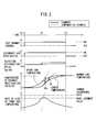
- FIG. 2 is a time chart of first operational control in the present embodiment.
- FIG. 2 shows the operating state when cold starting an internal combustion engine.
- FIG. 2 shows as the temperature of the exhaust purification catalyst 20, the temperature of the center part of the exhaust purification catalyst 20 (center temperature) in addition to the front end temperature. Further, a working example is shown by the solid line, while a comparative example is shown by the broken line.
- fast warmup control in which the ignition timing and fuel injection timing at each combustion chamber 5 etc. are adjusted to rise the temperature of the exhaust gas which flows out from the combustion chamber 5 is performed.
- fuel is injected from each fuel injector 11 in the compression stroke. That is, fuel is injected from the fuel injector 11 while the piston 3 is rising.
- the fuel which is injected from the fuel injector 11 collects around the spark plug 10 and becomes higher in stratification degree. A state is formed where even if greatly delaying the ignition timing, ignition becomes possible. Further, by greatly delaying the ignition timing, it is possible to make the temperature of the exhaust gas which flows out from the combustion chamber 5 rise.
- the internal combustion engine of the present embodiment is formed to enable change of the ratio (Qp/Qd: injection distribution ratio) of the fuel injection amount Qp from a fuel injector 12 which injects fuel to the intake port 7 to the fuel injection amount Qd from a fuel injector 11 which directly injects fuel to the combustion chamber 5.
- the example is shown of maintaining the overall amount of feed of fuel which is fed to the combustion chamber 5 constant while changing the injection distribution ratio.
- the injection distribution ratio is set to a predetermined injection distribution ratio.
- the overall fuel injection amount from the fuel injectors 11 and 12 is controlled so that the exhaust gas which flows out from the combustion chamber 5 becomes rich in air-flow ratio (less than stoichiometric air-fuel ratio) of the exhaust gas. In this case, it is also possible to inject fuel from the fuel injector 11 in the suction stroke in addition to the compression stroke.
- the secondary air feed device 25 is started up. That is, air is fed to the exhaust manifold 19. Control is performed so that the air-fuel ratio of the exhaust gas which flows out from each combustion chamber 5 becomes rich.
- the exhaust gas which flows out from the combustion chamber 5 contains carbon monoxide and unburned hydrocarbons. The carbon monoxide and unburned hydrocarbons contact the oxygen whereby an oxidation reaction occurs.
- the temperature of the exhaust gas rises and high temperature exhaust gas flows into the exhaust purification catalyst 20. A rise in the front end temperature and center temperature of the exhaust purification catalyst 20 is promoted and a temperature difference DT is formed between the front end temperature and the center temperature.
- FIG. 2 shows the extent of rise per unit time of the front end temperature of the exhaust purification catalyst 20, that is, the rate of rise of the front end temperature.
- the rate of rise of the front end temperature is increased along with the elapse of time. The more the rate of rise of the front end temperature is increased, the greater the temperature difference DT between the front end temperature and the center temperature.
- damage such as cracks, etc., occur in the exhaust purification catalyst 20. That is, if maintaining the operating state at the time t1, the rate of rise of the front end temperature ends up exceeding the damage occurrence rate at which the exhaust purification catalyst 20 will be damaged.
- control is performed to continue the feed of air by the secondary air feed device 25 while increasing the injection distribution ratio which is the ratio of the fuel injection amount of the fuel injector 12 to the fuel injection amount of the fuel injector 11. That is, control is performed to increase the ratio of the amount of fuel which is injected to the engine intake passage to the amount of fuel which is directly injected into the cylinder. In this way, by increasing the ratio of the amount of fuel injected to the engine intake passage, it is possible to lower the stratification degree (richness) around the spark plug 10. It is possible to raise the homogeneity of the air-fuel mixture when igniting fuel in the combustion chamber 5. As a result, the combustion of the fuel becomes gentler and the combustion speed becomes slower.
- the amount of CO which is contained in the exhaust gas which flows out from the combustion chamber 5 to the exhaust port 9 is reduced. For this reason, it is possible to suppress the oxidation reaction of the carbon monoxide which occur by the feed of air from the secondary air feed device 25 and suppress the rise in temperature of the exhaust gas which is fed to the exhaust purification catalyst 20.
- a rate judgment value for changing the injection distribution ratio is set in advance.
- the rate judgment value for changing the injection distribution ratio can be set lower than the damage occurrence rate.
- the rate of rise of the front end temperature exceeds the predetermined rate judgment value.
- the temperature gradient of the exhaust purification catalyst 20 in the direction of flow of exhaust gas becomes higher. If the front end temperature rises by the rate as it is, it is judged that the exhaust purification catalyst 20 will be damaged. For this reason, at the time t2, control is performed to increase the injection distribution ratio (Qp/Qd).
- the injection distribution ratio is changed while the amount of feed of fuel as a whole which is fed to each combustion chamber 5 is maintained substantially constant. Further, the amount of air which is fed by the secondary air feed device 25 is also maintained substantially constant.
- control is performed to maintain the injection distribution ratio after change.
- the front end temperature and center temperature of the exhaust purification catalyst 20 become the warmup end temperature or more. For this reason, at the time t3, the control for promoting the rise in temperature of the exhaust purification catalyst 20 is stopped. That is, the fast warmup control is ended and the secondary air feed device is shut down. Furthermore, the injection distribution ratio is returned to the original injection distribution ratio before the change. The rate of rise of the front end temperature of the exhaust purification catalyst 20 gently falls.
- control is performed to maintain the injection distribution ratio which is set at the time t1 without changing the injection distribution ratio at the time t2.
- the rate of rise of the front end temperature reaches the damage occurrence rate of the exhaust purification catalyst 20.
- the temperature difference DTc between the front end temperature and the center temperature increases along with the elapse of time and sooner or later damage occurs.
- the injection distribution ratio is changed when the rate of rise of the front end temperature of the exhaust purification catalyst exceeds the rate judgment value, so it is possible to reduce the amount of exhaust of carbon monoxide susceptible to an oxidation reaction in the engine exhaust passage and possible to suppress the rise in temperature of the exhaust gas which is fed to the exhaust purification catalyst 20. Further, to continue the operation without shutting down the secondary air feed device 25, it is possible to suppress the slowdown in the temperature rise of the exhaust purification catalyst 20. It is possible to raise the temperature of the exhaust purification catalyst 20 as a whole to the activation temperature or more in a short time and possible to suppress deterioration of the properties of the exhaust gas which is discharged to the outside.
- the secondary air feed device in the operational control of another comparative example, it is possible to temporarily shut down the secondary air feed device when the rate of rise of the front end temperature of the exhaust purification catalyst reaches the rate judgment value. After this, when the rate of rise of the front end temperature falls, the secondary air feed device can be restarted.
- the load of the air pump of the secondary air feed device becomes larger or noise or vibration accompanying startup and shutdown is generated.
- FIG. 3 shows a flowchart of first operational control in the present embodiment.
- the startup of the internal combustion engine is detected.
- the fast warmup control is started, while at step 113, the secondary air feed device is started up.
- the start of the fast warmup control and the startup of the secondary air feed device can be performed at the same timing. Alternatively, the startup of the secondary air feed device may be performed before the start of the fast warmup control.
- the front end temperature of the exhaust purification catalyst 20 is acquired.
- the temperature sensor 43 is used to detect the front end temperature of the exhaust purification catalyst 20.
- the device for acquiring the front end temperature of the exhaust purification catalyst 20 is not limited to a temperature sensor. Any device or control may be used to acquire it. For example, the cumulative value of the amount of intake air of the air which is fed to each combustion chamber may be used as the basis to estimate the front end temperature of the exhaust purification catalyst.
- step 115 it is judged if the end timing of warmup of the exhaust purification catalyst 20 has been reached.
- the end timing of warmup of the exhaust purification catalyst 20 is preferably the timing at which the exhaust purification catalyst 20 as a whole reaches the activation temperature or more.
- the judgment value of the cumulative value of the intake air amount when the center part of the exhaust purification catalyst 20 becomes a predetermined warmup end temperature or more is set in advance.
- the intake air amount which is detected by the air flow meter 16 is used as the basis to calculate the cumulative amount of the intake air amount and the end timing of warmup is judged when this cumulative value becomes larger than a predetermined judgment value.
- the judgment of the end timing of warmup is not limited to this embodiment. It is possible to stop control for promoting the rise in temperature of the exhaust purification catalyst 20 when it is judged that the temperature of the exhaust purification catalyst 20 as a whole in the direction of flow of the exhaust has been the activation temperature.
- step 115 When, it is judged at step 115 that the timing is the end of warmup of the exhaust purification catalyst 2, the routine proceeds to step 116 and step 117.
- step 116 the secondary air feed device is stopped, while at step 117, the fast warmup control is ended. Note that the secondary air feed device may be stopped and the fast warmup control may be ended at substantially the same timing. Alternatively, the fast warmup control may be ended first.
- step 118 it is judged if the detection of the front end temperature of step 114 is the second time or more. If the detection of the front end temperature is the first time, the routine again returns to step 114. If the detection of the front end temperature of the exhaust purification catalyst 20 is the second time or more, the routine proceeds to step 119. At step 119, the rate of rise of the front end temperature is calculated. The rate of rise of the front end temperature can, for example, be calculated by using the detected values of the front end temperature of the most recent consecutive two detection operations.
- step 120 it is judged if the rate of rise of the front end temperature is larger than the predetermined rate judgment value.
- the rate of rise of the front end temperature of the exhaust purification catalyst 20 is the rate judgment value or less, it is possible to maintain the current state while raising the temperature of the exhaust purification catalyst 20. In this case, the routine returns to step 114 where the front end temperature is again detected.
- step 120 When at step 120 the rate of rise of the front end temperature exceeds the rate judgment value, the routine proceeds to step 121. In this case, if maintaining the current operating state, it is possible to judge that the exhaust purification catalyst will be damaged.
- the injection distribution ratio of the fuel injector 11 and the fuel injector 12 is changed.
- control is performed to raise the ratio of the fuel injection amount of the fuel injector 12 which injects fuel to the port to the fuel injection amount of the fuel injector 11 which injects fuel to the combustion chamber 5.
- control is performed to increase the predetermined injection distribution ratio.
- step 122 it is judged if the end timing of warmup has been reached.
- the current operational control is continued. That is, the injection distribution ratio is maintained until the end timing of warmup is reached to raise the temperature of the exhaust purification catalyst 20.
- the routine proceeds to step 116.
- step 116 and step 117 as explained above, the secondary air feed device is shut down and the fast warmup control is ended.
- the rate of rise of temperature of the upstream side end part of the exhaust purification catalyst 20 is detected and, when the rate of rise exceeds the predetermined rate judgment value, it is judged that the exhaust purification catalyst will be damaged, but the invention is not limited to this embodiment. It is possible to use a variable based on the acquired temperature of the upstream side end part for the judgment. For example, it is also possible to set in advance the temperature judgment value of the upstream side end part and, when the temperature of the upstream side end part exceeds the temperature judgment value, judge that the exhaust purification catalyst will be damaged.
- a temperature sensor which detects the temperature at the center part of the exhaust purification catalyst to calculate the temperature difference between the front end temperature and the temperature of the center part and, when the calculated temperature difference exceeds a predetermined judgment value, judge that the exhaust purification catalyst will be damaged.
- FIG. 4 shows a time chart of the second operational control in the present embodiment.
- the second operational control at the time t0, the internal combustion engine is started up and, at the time t1, the fast warmup control is started and, furthermore, the secondary air feed device is started up in the same way as the first operational control.
- the rate of rise of the front end temperature of the exhaust purification catalyst 20 exceeds the rate judgment value and the injection distribution ratio is changed in the same way as the first operational control.
- the rate of rise of the front end temperature of the exhaust purification catalyst 20 is less than the rate judgment value.
- control is performed to decrease the ratio of the fuel injection amount of the fuel injector 12 with respect to the fuel injection amount of the fuel injector 11. That is, control is performed to reduce the injection distribution ratio.
- control is performed to gradually lower the injection distribution ratio by a predetermined speed. By performing this control, it is possible to suppress the drop in the rate of rise of the front end temperature of the exhaust purification catalyst 20 and possible to raise the exhaust purification catalyst as a whole to the activation temperature or more in a short time.
- the temperature of the center part of the exhaust purification catalyst 20 reaches the warmup end temperature and the control for promoting the rise in temperature of the exhaust purification catalyst 20 is ended. It is learned that compared with the time t3 at which the control for promoting the rise in temperature of the exhaust purification catalyst 2 in the first operational control shown in FIG. 2 ends, the end timing of the rise of temperature of the exhaust purification catalyst 20 becomes earlier. In this way, in the second operational control, it is possible to use the first operational control to raise the temperature of the exhaust purification catalyst 20 in a short time.
- the injection distribution ratio is changed to a predetermined injection distribution ratio and maintained constant.
- the injection distribution ratio is decreased by a predetermined value, but the invention is not limited to this. Control may also be performed so that the greater the rate of rise of the front end temperature of the exhaust purification catalyst 20, the more the injection distribution ratio is increased. That is, control may also be performed so as to estimate the rate of rise of the front end temperature and increase the ratio of the fuel which is injected into the engine intake passage the greater the rate of rise of the front end temperature.
- the control for continuously changing the injection distribution ratio can be started, for example, at any timing after starting up the internal combustion engine. For example, it can be started at the time t1 or the time t2 in FIG. 2 and FIG. 4. Furthermore, it can be started from the time t4 at FIG. 4. Due to this control, when the rate of rise of the front end temperature is large, it is possible to more reliably avoid the rate of rise of the front end temperature from exceeding the damage occurrence rate. Further, when the rate of rise of the front end temperature becomes small, it is possible to increase the rate of rise of the front end temperature and raise the temperature of the exhaust purification catalyst 20 as a whole to the activation temperature or more in a short time. In this way, it is possible to make the temperature of the exhaust purification catalyst as a whole the activation temperature or more in a short time.
- control when performing control to continuously change the injection distribution ratio, it is preferable to perform control so that the rate of rise of the front end temperature of the exhaust purification catalyst 20 is maintained near the rate judgment value.
- the injection timing of the fuel injector 11 which directly injects fuel into the cylinder.
- the fuel injector 11 when the fuel injector 11 is injecting fuel in the suction stroke and injecting fuel in the compression stroke, when the rate of rise of the front end temperature of the exhaust purification catalyst 20 exceeds the rate judgment value, it is possible to increase the ratio of the fuel injection amount at the suction stroke.
- the fuel injector 11 when the fuel injector 11 is only injecting fuel at the compression stroke, it is possible to make the injection timing earlier. By performing either of these controls, it is possible to weaken the stratification degree of the air-fuel mixture around the spark plug and suppress the amount of exhaust of the carbon monoxide which flows out from each combustion chamber 5. For this reason, it is possible to suppress the amount of oxidation of carbon monoxide and suppress the rise in temperature of the exhaust purification catalyst.
Landscapes
- Engineering & Computer Science (AREA)
- Chemical & Material Sciences (AREA)
- Combustion & Propulsion (AREA)
- Mechanical Engineering (AREA)
- General Engineering & Computer Science (AREA)
- Chemical Kinetics & Catalysis (AREA)
- Health & Medical Sciences (AREA)
- Toxicology (AREA)
- Exhaust Gas After Treatment (AREA)
- Electrical Control Of Air Or Fuel Supplied To Internal-Combustion Engine (AREA)
Abstract
An internal combustion engine provided with a secondary air feed device which feeds air to an upstream side of an exhaust purification catalyst, a cylinder fuel injector which injects fuel to an inside of a combustion chamber, and an intake passage fuel injector which injects fuel to an engine intake passage. When the rate of rise of temperature of the upstream side end part of the exhaust purification catalyst exceeds a rate judgment value, the control device increases the ratio of the fuel injection amount of the intake passage fuel injector to the fuel injection amount of the cylinder fuel injector while feeding air to the engine exhaust passage by the secondary air feed device.
Description
The present invention relates to an internal combustion engine.
It is known to arrange an exhaust purification catalyst in an engine exhaust passage of an internal combustion engine to remove the carbon monoxide (CO), hydrocarbons (HC), nitrogen oxides (NOX), and other constituents which are contained in the exhaust gas. The exhaust purification catalyst has an activation temperature which enables removal of the constituents of the exhaust gas with a high efficiency. Right after startup after an internal combustion engine has been shut down for a long time, an exhaust purification catalyst is at less than the activation temperature. It is preferable to raise the temperature of the exhaust purification catalyst fast. On the other hand, if raising the temperature of the exhaust purification catalyst too much, the catalyst deteriorates etc., so the exhaust purification catalyst is preferably maintained at a suitable temperature range.
In the prior art, to raise the temperature of the exhaust purification catalyst at the time of a cold start etc. in a short time, it is known to arrange a secondary air feed device which feeds air to the engine exhaust passage at the upstream side of the exhaust purification catalyst. The secondary air feed device feeds secondary air to the engine exhaust passage to raise the concentration of oxygen. The feed of secondary air can be used to oxidize the unburned hydrocarbon (HC) or carbon monoxide (CO) which is contained in the exhaust gas to thereby raise the temperature of the exhaust gas and promote the rise in temperature of the exhaust purification catalyst.
Japanese Patent Publication No. 05-195760A discloses an engine which is provided with a secondary air feeding means which is provided with a pump which supplies new air to an exhaust manifold or catalytic converter. In this engine, it is disclosed to shut down operation of the pump of the secondary air feeding means by a signal from an exhaust temperature sensor, catalyst temperature sensor, or linear oxygen concentration sensor when the activation of the catalytic converter is obstructed and when a temperature is reached at which damage occurs.
Japanese Patent Publication No. 2000-120471A discloses a cylinder injection type engine which is provided with a secondary air feeding means which feeds secondary air to the exhaust passage to activate an exhaust gas purification catalyst. It is disclosed that when judging that the exhaust gas purification catalyst is in a high temperature state, an engine injects fuel to become lean in the period from the suction stroke to the compression stroke, then injects fuel in the expansion stroke and, furthermore, uses the secondary air feeding means to feed secondary air.
Japanese Patent Publication No. 2008-095532A discloses an internal combustion engine which is provided with a cylinder injection type injector and a port injection type injector. This publication discloses to provide an ECU of the internal combustion engine with a catalyst warmup reset control part which fixes the ratio of fuel injection by the cylinder injection type injector and port injection type injector after the end of catalyst warmup control until predetermined conditions are reached. Further, Japanese Patent Publication No. 2007-168563A discloses a hybrid vehicle which is provided with an internal combustion engine and electric motor where the increase of the amount of fuel feed to the internal combustion engine to adjust the temperature of the catalyst is set based on the chargeable power.
When using a secondary air feed device to raise the temperature of an exhaust purification catalyst, high temperature exhaust gas flows in from the upstream side end part of the exhaust purification catalyst. For this reason, the upstream side end part of the exhaust purification catalyst rapidly rises in temperature and a temperature difference arises between the temperature of the center part of the exhaust purification catalyst or the downstream side end part of the exhaust purification catalyst. Furthermore, when the exhaust purification catalyst has an oxidation function, if the temperature of the upstream side end part rises, the upstream side end part is improved in oxidation ability and the hydrocarbons or carbon monoxide is oxidized and heat of oxidation is generated. As a result, a rise in temperature of the upstream side end part is promoted and the temperature difference between the upstream side end part and center part and the temperature difference between the upstream side end part and downstream side end part become larger.
If the temperature difference in the exhaust purification catalyst becomes larger in the direction toward the downstream side, the base material of the exhaust purification catalyst is liable to warp and be damaged. For example, the base material of the exhaust purification catalyst is liable to end up breaking. Alternatively, if the upstream side end part rises too much in temperature, the upstream side end part is liable to deteriorate in catalyst performance. To avoid such damage of the exhaust purification catalyst, for example, it is possible to perform control to stop the feed of secondary air when the exhaust purification catalyst is liable to reach a state where it would be damaged.
However, in this case, for example, even if the upstream side end part of the exhaust purification catalyst reaches the activation temperature, sometimes the center part and downstream side end part of the exhaust purification catalyst still have not been sufficiently raised in temperature and have not reached the activation temperature. For this reason, if stopping the feed of secondary air, the exhaust gas is not sufficiently purified at the center part and downstream side end part of the exhaust purification catalyst and the exhaust purification catalyst as a whole is liable to be unable to exhibit sufficient purification ability. That is, there is the problem that raising the temperature at the center part and downstream side of the exhaust purification catalyst takes time and therefore time is taken until a sufficient removal rate is exhibited.
The present invention has as its object to provide an internal combustion engine which is provided with an exhaust purification catalyst and a secondary air feed device and which can keep the exhaust purification catalyst from being damaged while raising the temperature of the exhaust purification catalyst as a whole in a short time.
The internal combustion engine of the present invention is provided with an exhaust purification catalyst which is arranged at an engine exhaust passage, a secondary air feed device which feeds air to the engine exhaust passage at an upstream side from the exhaust purification catalyst, a cylinder fuel injector which injects fuel to an inside of a combustion chamber, an intake passage fuel injector which injects fuel to an engine intake passage, a temperature acquiring device which acquires a temperature of an upstream side end part of the exhaust purification catalyst, and a control device. The control device acquires the temperature of the upstream side end part of the exhaust purification catalyst when feeding air to the engine exhaust passage by the secondary air feed device. When a variable based on the acquired temperature of the upstream side end part exceeds a predetermined judgment value, the control device increases a ratio of the fuel injection amount of the intake passage fuel injector to the fuel injection amount of the cylinder fuel injector while performing a control to feed air to the engine exhaust passage by the secondary air feed device.
In the above invention, the control device may use the temperature of the upstream side end part of the exhaust purification catalyst as the basis to estimate a rate of rise of temperature of the upstream side end part of the exhaust purification catalyst and, when the rate of rise exceeds a predetermined rate judgment value, the control device increases the ratio of the fuel injection amount of the intake passage fuel injector to the fuel injection amount of the cylinder fuel injector while performing a control to feed air to the engine exhaust passage by the secondary air feed device.
In the above invention, the control device may use the temperature of the upstream side end part of the exhaust purification catalyst as the basis to estimate a rate of rise of temperature of the upstream side end part of the exhaust purification catalyst and increase the ratio of the fuel injection amount of the intake passage fuel injector to the fuel injection amount of the cylinder fuel injector the greater the rate of rise.
In the above invention, the control device may reduce the ratio of the fuel injection amount of the intake passage fuel injector to the fuel injection amount of the cylinder fuel injector when the rate of rise exceeds the rate judgment value, then becomes less than the rate judgment value.
In the above invention, when the temperature of the upstream side end part of the exhaust purification catalyst exceeds a predetermined temperature judgment value, the control device may increase the ratio of the fuel injection amount of the intake passage fuel injector to the fuel injection amount of the cylinder fuel injector while performing a control to feed air to the engine exhaust passage by the secondary air feed device.
According to the present invention, it is possible to provide an internal combustion engine which is provided with an exhaust purification catalyst and a secondary air feed device and which can raise the temperature of the exhaust purification catalyst as a whole in a short time while keeping the exhaust purification catalyst from being damaged.
Referring to FIG. 1 to FIG. 4, an internal combustion engine in an embodiment will be explained. In the present embodiment, an internal combustion engine which is installed in a vehicle will be taken up as an example for the explanation.
FIG. 1 is a schematic view of an internal combustion engine in the present embodiment. The internal combustion engine in the present embodiment is a spark ignition type. The internal combustion engine is provided with an engine body 1. The engine body 1 includes a cylinder block 2 and a cylinder head 4. Inside of the cylinder block 2, pistons 3 are arranged. The pistons 3 move in a reciprocating manner inside of the cylinder block 2.
In the present embodiment, the space which is surrounded by the top surface of each piston 3 and the cylinder head 4 when the piston 3 reaches top dead center is called a "combustion chamber". A combustion chamber 5 is formed for each cylinder. The combustion chamber 5 is connected to an engine intake passage and engine exhaust passage. The engine intake passage is a passage for feeding fuel or an air-fuel mixture of fuel and air to the combustion chamber 5. The engine exhaust passage is a passage for exhausting exhaust gas which is produced by combustion of fuel from the combustion chamber 5.
The cylinder head 4 is formed with intake ports 7 and exhaust ports 9. An intake valve 6 is formed arranged at the end part of each intake port 7 to be able to open and close the engine intake passage which communicates with the combustion chamber 5. An exhaust valve 8 is formed arranged at the end part of each exhaust port 9 to be able to open and close the engine exhaust passage which communicates with the combustion chamber 5. The cylinder head 4 has ignition devices constituted by spark plugs 10 fixed to it.
The internal combustion engine in the present embodiment is provided with cylinder fuel injectors constituted by fuel injectors 11 which inject fuel to the insides of the combustion chambers 5. Each fuel injector 11 directly injects fuel to the inside of a cylinder. At the top surface of each piston 3, a cavity 3a is formed which extends from below the fuel injector 11 to below the spark plug 10. By injecting fuel from the fuel injector 11 in the compression stroke, the air-fuel mixture which includes fuel flows along a cavity 3a. The fuel can collect near the spark plug 10 to raise the stratification degree. Further, the internal combustion engine in the present embodiment is provided with intake passage fuel injectors constituted by fuel injectors 12 which inject fuel to the engine intake passage. Each fuel injector 12 in the present embodiment is arranged so as to inject fuel to the inside of the intake port 7.
The internal combustion engine of the present embodiment feeds fuel which is stored in a fuel tank to the fuel injectors 11 and 12 by a fuel pump. Further, in the channel which feeds fuel to the fuel injectors 11 which inject fuel into the cylinders, a high pressure pump is arranged to raise the pressure of the fuel.
The intake port 7 of each cylinder is connected through a corresponding intake runner 13 to a surge tank 14. The surge tank 14 is connected through an intake duct 15 to an air cleaner 23. At the inside of the intake duct 15, an air flow meter 16 which detects the amount of intake air is arranged. Inside of the intake duct 15, a throttle valve 18 which is driven by a step motor 17 is arranged. On the other hand, the exhaust port 9 of each cylinder is connected to an exhaust manifold 19. The exhaust manifold 19 is connected through an exhaust pipe 22 to an exhaust treatment device 21. The exhaust treatment device 21 in the present embodiment includes an exhaust purification catalyst 20. As the exhaust purification catalyst 20, it is possible to employ any catalyst which has an activation temperature for reaching a predetermined purification rate. For example, a three-way catalyst, oxidation catalyst, NOX removal catalyst, or other catalyst can be employed.
The internal combustion engine in the present embodiment is provided with an electronic control unit 31 which functions as a control device. The electronic control unit 31 in the present embodiment includes a digital computer. The electronic control unit 31 includes components which are connected to each other through a bidirectional bus 32 such as a RAM (random access memory) 33, ROM (read only memory) 34, CPU (microprocessor) 35, input port 36, and output port 37.
An output signal of the air flow meter 16 is input through a corresponding AD converter 38 to the input port 36. An accelerator pedal 40 is connected to a load sensor 41. The load sensor 41 generates an output voltage which is proportional to the amount of depression of the accelerator pedal 40. This output voltage is input through a corresponding AD converter 38 to the input port 36.
A crank angle sensor 42, for example, generates an output pulse every time a crankshaft rotates by a predetermined angle. This output pulse is input to the input port 36. The output of the crank angle sensor 42 can be used to detect the engine speed. Further, the output of the crank angle sensor 42 can be used to detect the crank angle at any time.
When referring to the ratio of the air and fuel (hydrocarbons) in the gas which is fed to the engine exhaust passage etc. upstream of the exhaust treatment device 21, including the gas burned at the combustion chamber 5, as the "air-fuel ratio (A/F) of the exhaust gas", the engine exhaust passage is provided with an air-fuel ratio sensor 44 which detects the air-fuel ratio of the exhaust gas of the gas which flows out from each combustion chamber 5. Further, at the upstream side end part of the exhaust purification catalyst 20, a temperature sensor 43 is arranged as a temperature detector which detects the temperature of the upstream side end part of the exhaust purification catalyst 20 (below, referred to as the "front end temperature"). The temperature sensor 43 functions as a temperature acquiring device which acquires a front end temperature. The output of the air-fuel ratio sensor 44 and the output of the temperature sensor 43 are input through corresponding AD converters 38 to the input port 36.
The output port 37 of the electronic control unit 31 is connected through corresponding drive circuits 39 to the fuel injectors 11 and 12 and spark plugs 10. The electronic control unit 31 in the present embodiment is formed so as to perform fuel injection control and ignition control. That is, the timing of injection of fuel and the amount of injection of fuel are controlled by the electronic control unit 31.
In the present embodiment, the fuel injectors 11 and the fuel injectors 12 are independently controlled. That is, the injection amount and injection timing of fuel from the fuel injectors 11 and the injection amount and injection timing of fuel from the fuel injectors 12 are controlled separately from each other.
Furthermore, the ignition timing of the spark plugs 10 is controlled by the electronic control unit 31. Further, the output port 37 is connected through a corresponding drive circuit 39 to the step motor 17 which drives the throttle valves 18. These devices are controlled by the electronic control unit 31.
The internal combustion engine of the present embodiment is provided with a secondary air feed device 25 which feeds air to the engine exhaust passage at the upstream side from the exhaust purification catalyst 20. The secondary air feed device 25 includes a secondary air feed passage 26 which connects the intake duct 15 and exhaust manifold 19. The secondary air feed passage 26 is connected to the intake duct 15 at downstream side of the air cleaner 23 and upstream side of the air flow meter 16. Further, the secondary air feed device 25 includes an electric motor drive type air pump 27 and air switching valve (ASV) 28. The air pump 27 pressurizes the air inside of the intake duct 15 and feeds it to the exhaust manifold 19. Further, at the secondary air feed passage 26, a check valve 29 is arranged for preventing the backflow of air. Between the air pump 27 and the air switching valve 28, a pressure sensor 30 which detects the pressure inside of the secondary air feed passage 26 is arranged.
The output of the pressure sensor 30 is input to the electronic control unit 31. Further, the output port 37 of the electronic control unit 31 is connected through a corresponding drive circuit 39 to the air pump 27 and the air switching valve 28. In this way, the secondary air feed device 25 is controlled by the electronic control unit 31.
The secondary air feed device 25 in the present embodiment is, for example, used in a state where the exhaust purification catalyst 20 is not sufficiently raised in temperature such as at the time of cold start of the internal combustion engine. That is, it is used when the exhaust purification catalyst 20 has not reached the activation temperature.
At the time of cold start of the internal combustion engine etc., the air switching valve 28 is opened and the air pump 27 is driven. Part of the air which passes through the air cleaner 23 passes through the secondary air feed passage 26 and is fed to the inside of the exhaust manifold 19. Oxygen is fed to the exhaust gas which flows through the exhaust manifold 19. The exhaust gas which flows out from each combustion chamber 5 includes unburned hydrocarbons or carbon monoxide. The exhaust gas which flows out from the combustion chamber 5 is a high temperature. By using the secondary air feed device to feed oxygen, it is possible to oxidize the unburned hydrocarbons or carbon monoxide. The heat of oxidation at this time can be used to make the temperature of the exhaust gas rise.
It is possible to feed the high temperature exhaust gas to the exhaust purification catalyst 20 and possible to promote the rise of temperature of the exhaust purification catalyst 20. As a result, it is possible to raise the temperature of the exhaust purification catalyst 20 to the activation temperature or more in a short time. That is, it is possible to keep the exhaust gas from being discharged into the atmosphere in the state where it cannot be sufficiently purified by the exhaust purification catalyst 20.
Alternatively, when the exhaust purification catalyst 20 has an oxidation function, it is possible to feed air to the exhaust gas to make the exhaust gas lean in air-fuel ratio (more than stoichiometric air-fuel ratio) of the exhaust gas and feed it to the exhaust purification catalyst 20. It is possible to oxidize the unburned hydrocarbons and carbon monoxide in the exhaust purification catalyst 20 and possible to promote the rise in temperature of the exhaust purification catalyst 20.
In this regard, if using the secondary air feed device 25 to feed air, the exhaust gas which flows into the exhaust purification catalyst 20 becomes a high temperature and the temperature of the upstream side end part of the exhaust purification catalyst 20 (front end temperature) rapidly rises. In the first operational control of the present embodiment, when it is judged based on the front end temperature of the exhaust purification catalyst 20 that the exhaust purification catalyst will be damaged, control is performed to raise the ratio of the fuel injection amount of the fuel injector 12 to the fuel injection amount of the fuel injector 11 while feeding air to the engine exhaust passage by the secondary air feed device 25. That is, control is performed to increase the ratio of the amount of fuel which is fed to the engine intake passage. In the present embodiment, when a predetermined variable based on the front end temperature of the exhaust purification catalyst 20 exceeds a predetermined judgment value, it is judged that the exhaust purification catalyst will be damaged.
FIG. 2 is a time chart of first operational control in the present embodiment. FIG. 2 shows the operating state when cold starting an internal combustion engine. FIG. 2 shows as the temperature of the exhaust purification catalyst 20, the temperature of the center part of the exhaust purification catalyst 20 (center temperature) in addition to the front end temperature. Further, a working example is shown by the solid line, while a comparative example is shown by the broken line.
At the time t0, the internal combustion engine is started up. Exhaust gas flows out from each combustion chamber 5 after combustion and flows into the exhaust purification catalyst 20. The exhaust purification catalyst 20 gently rises in front end temperature and center temperature.
At the time t1 right after cold starting the internal combustion engine, fast warmup control in which the ignition timing and fuel injection timing at each combustion chamber 5 etc. are adjusted to rise the temperature of the exhaust gas which flows out from the combustion chamber 5 is performed. In the fast warmup control of the present embodiment, fuel is injected from each fuel injector 11 in the compression stroke. That is, fuel is injected from the fuel injector 11 while the piston 3 is rising. The fuel which is injected from the fuel injector 11 collects around the spark plug 10 and becomes higher in stratification degree. A state is formed where even if greatly delaying the ignition timing, ignition becomes possible. Further, by greatly delaying the ignition timing, it is possible to make the temperature of the exhaust gas which flows out from the combustion chamber 5 rise.
The internal combustion engine of the present embodiment is formed to enable change of the ratio (Qp/Qd: injection distribution ratio) of the fuel injection amount Qp from a fuel injector 12 which injects fuel to the intake port 7 to the fuel injection amount Qd from a fuel injector 11 which directly injects fuel to the combustion chamber 5. In this embodiment of the present embodiment, the example is shown of maintaining the overall amount of feed of fuel which is fed to the combustion chamber 5 constant while changing the injection distribution ratio. At the time t1, the injection distribution ratio is set to a predetermined injection distribution ratio. Further, the overall fuel injection amount from the fuel injectors 11 and 12 is controlled so that the exhaust gas which flows out from the combustion chamber 5 becomes rich in air-flow ratio (less than stoichiometric air-fuel ratio) of the exhaust gas. In this case, it is also possible to inject fuel from the fuel injector 11 in the suction stroke in addition to the compression stroke.
Further, at the time t1, the secondary air feed device 25 is started up. That is, air is fed to the exhaust manifold 19. Control is performed so that the air-fuel ratio of the exhaust gas which flows out from each combustion chamber 5 becomes rich. The exhaust gas which flows out from the combustion chamber 5 contains carbon monoxide and unburned hydrocarbons. The carbon monoxide and unburned hydrocarbons contact the oxygen whereby an oxidation reaction occurs. The temperature of the exhaust gas rises and high temperature exhaust gas flows into the exhaust purification catalyst 20. A rise in the front end temperature and center temperature of the exhaust purification catalyst 20 is promoted and a temperature difference DT is formed between the front end temperature and the center temperature.
FIG. 2 shows the extent of rise per unit time of the front end temperature of the exhaust purification catalyst 20, that is, the rate of rise of the front end temperature. The rate of rise of the front end temperature is increased along with the elapse of time. The more the rate of rise of the front end temperature is increased, the greater the temperature difference DT between the front end temperature and the center temperature. In each case, damage such as cracks, etc., occur in the exhaust purification catalyst 20. That is, if maintaining the operating state at the time t1, the rate of rise of the front end temperature ends up exceeding the damage occurrence rate at which the exhaust purification catalyst 20 will be damaged.
Therefore, in the first operational control of the present embodiment, control is performed to continue the feed of air by the secondary air feed device 25 while increasing the injection distribution ratio which is the ratio of the fuel injection amount of the fuel injector 12 to the fuel injection amount of the fuel injector 11. That is, control is performed to increase the ratio of the amount of fuel which is injected to the engine intake passage to the amount of fuel which is directly injected into the cylinder. In this way, by increasing the ratio of the amount of fuel injected to the engine intake passage, it is possible to lower the stratification degree (richness) around the spark plug 10. It is possible to raise the homogeneity of the air-fuel mixture when igniting fuel in the combustion chamber 5. As a result, the combustion of the fuel becomes gentler and the combustion speed becomes slower. The amount of CO which is contained in the exhaust gas which flows out from the combustion chamber 5 to the exhaust port 9 is reduced. For this reason, it is possible to suppress the oxidation reaction of the carbon monoxide which occur by the feed of air from the secondary air feed device 25 and suppress the rise in temperature of the exhaust gas which is fed to the exhaust purification catalyst 20.
In the operational control in the present embodiment, a rate judgment value for changing the injection distribution ratio is set in advance. The rate judgment value for changing the injection distribution ratio can be set lower than the damage occurrence rate.
At the time t2, the rate of rise of the front end temperature exceeds the predetermined rate judgment value. At this time, the temperature gradient of the exhaust purification catalyst 20 in the direction of flow of exhaust gas becomes higher. If the front end temperature rises by the rate as it is, it is judged that the exhaust purification catalyst 20 will be damaged. For this reason, at the time t2, control is performed to increase the injection distribution ratio (Qp/Qd). In the present embodiment, the injection distribution ratio is changed while the amount of feed of fuel as a whole which is fed to each combustion chamber 5 is maintained substantially constant. Further, the amount of air which is fed by the secondary air feed device 25 is also maintained substantially constant. In the first operational control of the present embodiment, from the time t2 to the time t3, control is performed to maintain the injection distribution ratio after change.
By increasing the ratio of the fuel injection amount of the fuel injector 12 to the fuel injection amount of the fuel injector 11, it is possible to keep down the increase of the rate of rise of the front end temperature of the exhaust purification catalyst 20. Further, it is possible to gradually reduce the temperature difference DT between the front end temperature and center temperature of the exhaust purification catalyst 20. The rate of rise of the front end temperature exceeds the rate judgment value slightly, then becomes less than the rate judgment value. For this reason, it is possible to keep the rate of rise of the front end temperature from reaching the damage occurrence rate. Furthermore, it is possible to continue the feed of secondary air so as to continuously promote the rise in temperature of the exhaust purification catalyst 20.
At the time t3, the front end temperature and center temperature of the exhaust purification catalyst 20 become the warmup end temperature or more. For this reason, at the time t3, the control for promoting the rise in temperature of the exhaust purification catalyst 20 is stopped. That is, the fast warmup control is ended and the secondary air feed device is shut down. Furthermore, the injection distribution ratio is returned to the original injection distribution ratio before the change. The rate of rise of the front end temperature of the exhaust purification catalyst 20 gently falls.
In this regard, in the operational control of the comparative example of the broken line, control is performed to maintain the injection distribution ratio which is set at the time t1 without changing the injection distribution ratio at the time t2. The greater the rate of rise of the front end temperature of the exhaust purification catalyst 20, the greater the temperature gradient of the exhaust purification catalyst 20 in the direction of flow of exhaust gas. In the operational control of the comparative example, the rate of rise of the front end temperature reaches the damage occurrence rate of the exhaust purification catalyst 20. In the operational control of the comparative example, the temperature difference DTc between the front end temperature and the center temperature increases along with the elapse of time and sooner or later damage occurs.
As opposed to this, in the first operational control of the present embodiment, the injection distribution ratio is changed when the rate of rise of the front end temperature of the exhaust purification catalyst exceeds the rate judgment value, so it is possible to reduce the amount of exhaust of carbon monoxide susceptible to an oxidation reaction in the engine exhaust passage and possible to suppress the rise in temperature of the exhaust gas which is fed to the exhaust purification catalyst 20. Further, to continue the operation without shutting down the secondary air feed device 25, it is possible to suppress the slowdown in the temperature rise of the exhaust purification catalyst 20. It is possible to raise the temperature of the exhaust purification catalyst 20 as a whole to the activation temperature or more in a short time and possible to suppress deterioration of the properties of the exhaust gas which is discharged to the outside.
Alternatively, in the operational control of another comparative example, it is possible to temporarily shut down the secondary air feed device when the rate of rise of the front end temperature of the exhaust purification catalyst reaches the rate judgment value. After this, when the rate of rise of the front end temperature falls, the secondary air feed device can be restarted. However, if repeating the startup and shutdown of the secondary air feed device, the load of the air pump of the secondary air feed device becomes larger or noise or vibration accompanying startup and shutdown is generated. As opposed to this, in the first operational control of the present embodiment, it is possible to suppress the repeated startup and shutdown of the air pump 27 of the secondary air feed device 25 and possible to reduce the load of the air pump 27. Further, it is possible to suppress the noise or vibration accompanying startup and shutdown of the air pump 27.
FIG. 3 shows a flowchart of first operational control in the present embodiment. At step 111, the startup of the internal combustion engine is detected. At step 112, the fast warmup control is started, while at step 113, the secondary air feed device is started up. The start of the fast warmup control and the startup of the secondary air feed device can be performed at the same timing. Alternatively, the startup of the secondary air feed device may be performed before the start of the fast warmup control.
Next, at step 114, the front end temperature of the exhaust purification catalyst 20 is acquired. In the present embodiment, the temperature sensor 43 is used to detect the front end temperature of the exhaust purification catalyst 20. The device for acquiring the front end temperature of the exhaust purification catalyst 20 is not limited to a temperature sensor. Any device or control may be used to acquire it. For example, the cumulative value of the amount of intake air of the air which is fed to each combustion chamber may be used as the basis to estimate the front end temperature of the exhaust purification catalyst.
Next, at step 115, it is judged if the end timing of warmup of the exhaust purification catalyst 20 has been reached. The end timing of warmup of the exhaust purification catalyst 20 is preferably the timing at which the exhaust purification catalyst 20 as a whole reaches the activation temperature or more. In the present embodiment, the judgment value of the cumulative value of the intake air amount when the center part of the exhaust purification catalyst 20 becomes a predetermined warmup end temperature or more is set in advance. At step 115, the intake air amount which is detected by the air flow meter 16 is used as the basis to calculate the cumulative amount of the intake air amount and the end timing of warmup is judged when this cumulative value becomes larger than a predetermined judgment value.
The judgment of the end timing of warmup is not limited to this embodiment. It is possible to stop control for promoting the rise in temperature of the exhaust purification catalyst 20 when it is judged that the temperature of the exhaust purification catalyst 20 as a whole in the direction of flow of the exhaust has been the activation temperature.
When, it is judged at step 115 that the timing is the end of warmup of the exhaust purification catalyst 2, the routine proceeds to step 116 and step 117. At step 116, the secondary air feed device is stopped, while at step 117, the fast warmup control is ended. Note that the secondary air feed device may be stopped and the fast warmup control may be ended at substantially the same timing. Alternatively, the fast warmup control may be ended first.
When it is judged at step 115 that the timing is not the end of warmup of the exhaust purification catalyst 20, the routine proceeds to step 118. At step 118, it is judged if the detection of the front end temperature of step 114 is the second time or more. If the detection of the front end temperature is the first time, the routine again returns to step 114. If the detection of the front end temperature of the exhaust purification catalyst 20 is the second time or more, the routine proceeds to step 119. At step 119, the rate of rise of the front end temperature is calculated. The rate of rise of the front end temperature can, for example, be calculated by using the detected values of the front end temperature of the most recent consecutive two detection operations.
Next, at step 120, it is judged if the rate of rise of the front end temperature is larger than the predetermined rate judgment value. When at step 120 the rate of rise of the front end temperature of the exhaust purification catalyst 20 is the rate judgment value or less, it is possible to maintain the current state while raising the temperature of the exhaust purification catalyst 20. In this case, the routine returns to step 114 where the front end temperature is again detected.
When at step 120 the rate of rise of the front end temperature exceeds the rate judgment value, the routine proceeds to step 121. In this case, if maintaining the current operating state, it is possible to judge that the exhaust purification catalyst will be damaged.
At step 121, the injection distribution ratio of the fuel injector 11 and the fuel injector 12 is changed. In the first operational control, control is performed to raise the ratio of the fuel injection amount of the fuel injector 12 which injects fuel to the port to the fuel injection amount of the fuel injector 11 which injects fuel to the combustion chamber 5. In the present embodiment, control is performed to increase the predetermined injection distribution ratio.
Next, at step 122, it is judged if the end timing of warmup has been reached. When at step 122 the end timing of warmup has not been reached, the current operational control is continued. That is, the injection distribution ratio is maintained until the end timing of warmup is reached to raise the temperature of the exhaust purification catalyst 20. When at step 122 the end timing of warmup of the exhaust purification catalyst 20 has been reached, the routine proceeds to step 116. At step 116 and step 117, as explained above, the secondary air feed device is shut down and the fast warmup control is ended.
In the first operational control of the present embodiment, the rate of rise of temperature of the upstream side end part of the exhaust purification catalyst 20 is detected and, when the rate of rise exceeds the predetermined rate judgment value, it is judged that the exhaust purification catalyst will be damaged, but the invention is not limited to this embodiment. It is possible to use a variable based on the acquired temperature of the upstream side end part for the judgment. For example, it is also possible to set in advance the temperature judgment value of the upstream side end part and, when the temperature of the upstream side end part exceeds the temperature judgment value, judge that the exhaust purification catalyst will be damaged. Alternatively, it is also possible to arrange a temperature sensor which detects the temperature at the center part of the exhaust purification catalyst to calculate the temperature difference between the front end temperature and the temperature of the center part and, when the calculated temperature difference exceeds a predetermined judgment value, judge that the exhaust purification catalyst will be damaged.
FIG. 4 shows a time chart of the second operational control in the present embodiment. In the second operational control, at the time t0, the internal combustion engine is started up and, at the time t1, the fast warmup control is started and, furthermore, the secondary air feed device is started up in the same way as the first operational control. At the time t2, the rate of rise of the front end temperature of the exhaust purification catalyst 20 exceeds the rate judgment value and the injection distribution ratio is changed in the same way as the first operational control.
In the second operational control, at the time t4, the rate of rise of the front end temperature of the exhaust purification catalyst 20 is less than the rate judgment value. In the second operational control, when the rate of rise of the front end temperature becomes less than the rate judgment value, control is performed to decrease the ratio of the fuel injection amount of the fuel injector 12 with respect to the fuel injection amount of the fuel injector 11. That is, control is performed to reduce the injection distribution ratio. In the second operational control of the present embodiment, at the time t4 on, control is performed to gradually lower the injection distribution ratio by a predetermined speed. By performing this control, it is possible to suppress the drop in the rate of rise of the front end temperature of the exhaust purification catalyst 20 and possible to raise the exhaust purification catalyst as a whole to the activation temperature or more in a short time.
At the time t5, the temperature of the center part of the exhaust purification catalyst 20 reaches the warmup end temperature and the control for promoting the rise in temperature of the exhaust purification catalyst 20 is ended. It is learned that compared with the time t3 at which the control for promoting the rise in temperature of the exhaust purification catalyst 2 in the first operational control shown in FIG. 2 ends, the end timing of the rise of temperature of the exhaust purification catalyst 20 becomes earlier. In this way, in the second operational control, it is possible to use the first operational control to raise the temperature of the exhaust purification catalyst 20 in a short time.
In the above-mentioned first operational control and second operational control, at the time t2, the injection distribution ratio is changed to a predetermined injection distribution ratio and maintained constant. Alternatively, in the second operational control, at the time t4, furthermore, the injection distribution ratio is decreased by a predetermined value, but the invention is not limited to this. Control may also be performed so that the greater the rate of rise of the front end temperature of the exhaust purification catalyst 20, the more the injection distribution ratio is increased. That is, control may also be performed so as to estimate the rate of rise of the front end temperature and increase the ratio of the fuel which is injected into the engine intake passage the greater the rate of rise of the front end temperature.
The control for continuously changing the injection distribution ratio can be started, for example, at any timing after starting up the internal combustion engine. For example, it can be started at the time t1 or the time t2 in FIG. 2 and FIG. 4. Furthermore, it can be started from the time t4 at FIG. 4. Due to this control, when the rate of rise of the front end temperature is large, it is possible to more reliably avoid the rate of rise of the front end temperature from exceeding the damage occurrence rate. Further, when the rate of rise of the front end temperature becomes small, it is possible to increase the rate of rise of the front end temperature and raise the temperature of the exhaust purification catalyst 20 as a whole to the activation temperature or more in a short time. In this way, it is possible to make the temperature of the exhaust purification catalyst as a whole the activation temperature or more in a short time.
Further, when performing control to continuously change the injection distribution ratio, it is preferable to perform control so that the rate of rise of the front end temperature of the exhaust purification catalyst 20 is maintained near the rate judgment value. For example, it is possible to provide a range of judgment slightly smaller than the rate judgment value of the rate of rise of the front end temperature and change the injection distribution ratio so that the rate of rise of the front end temperature is maintained in that range of judgment.
Further, when it is judged that the exhaust purification catalyst will be damaged, it is possible to change the injection timing of the fuel injector 11 which directly injects fuel into the cylinder. For example, when the fuel injector 11 is injecting fuel in the suction stroke and injecting fuel in the compression stroke, when the rate of rise of the front end temperature of the exhaust purification catalyst 20 exceeds the rate judgment value, it is possible to increase the ratio of the fuel injection amount at the suction stroke. Alternatively, when the fuel injector 11 is only injecting fuel at the compression stroke, it is possible to make the injection timing earlier. By performing either of these controls, it is possible to weaken the stratification degree of the air-fuel mixture around the spark plug and suppress the amount of exhaust of the carbon monoxide which flows out from each combustion chamber 5. For this reason, it is possible to suppress the amount of oxidation of carbon monoxide and suppress the rise in temperature of the exhaust purification catalyst.
In the above control, it is possible to suitably change the order of the steps to an extent where the functions and actions are not changed.
In the above figures, the same or similar parts are assigned the same reference notations. Note that the above embodiments are illustrations and do not limit the invention. Further, in the above embodiments, changes of embodiments which are shown in the claims are included.
1 engine body
3 piston
3a cavity
5 combustion chamber
10 spark plug
11, 12 fuel injectors
20 exhaust purification catalyst
25 secondary air feed device
31 electronic control unit
43 temperature sensor
3 piston
3a cavity
5 combustion chamber
10 spark plug
11, 12 fuel injectors
20 exhaust purification catalyst
25 secondary air feed device
31 electronic control unit
43 temperature sensor
Claims (5)
- An internal combustion engine comprising:
an exhaust purification catalyst which is arranged at an engine exhaust passage;
a secondary air feed device which feeds air to the engine exhaust passage at an upstream side from the exhaust purification catalyst;
a cylinder fuel injector which injects fuel to an inside of a combustion chamber;
an intake passage fuel injector which injects fuel to an engine intake passage;
a temperature acquiring device which acquires a temperature of an upstream side end part of the exhaust purification catalyst; and
a control device; wherein
the control device acquires the temperature of the upstream side end part of the exhaust purification catalyst when feeding air to the engine exhaust passage by the secondary air feed device, and
when a variable based on an acquired temperature of the upstream side end part exceeds a predetermined judgment value, the control device increases a ratio of a fuel injection amount of the intake passage fuel injector to a fuel injection amount of the cylinder fuel injector while performing a control to feed air to the engine exhaust passage by the secondary air feed device. - The internal combustion engine according to claim 1, wherein
the control device uses the temperature of the upstream side end part of the exhaust purification catalyst as the basis to estimate a rate of rise of the temperature of the upstream side end part of the exhaust purification catalyst and,
when the rate of rise exceeds a predetermined rate judgment value, the control device increases the ratio of the fuel injection amount of the intake passage fuel injector to the fuel injection amount of the cylinder fuel injector while performing a control to feed air to the engine exhaust passage by the secondary air feed device. - The internal combustion engine according to claim 1, wherein
the control device uses the temperature of the upstream side end part of the exhaust purification catalyst as the basis to estimate a rate of rise of temperature of the upstream side end part of the exhaust purification catalyst and increases the ratio of the fuel injection amount of the intake passage fuel injector to the fuel injection amount of the cylinder fuel injector the greater the rate of rise. - The internal combustion engine according to claim 2, wherein
the control device decreases the ratio of the fuel injection amount of the intake passage fuel injector to the fuel injection amount of the cylinder fuel injector when the rate of rise exceeds the rate judgment value, then becomes less than the rate judgment value. - The internal combustion engine according to claim 1, wherein
when the temperature of the upstream side end part of the exhaust purification catalyst exceeds a predetermined temperature judgment value, the control device increases the ratio of the fuel injection amount of the intake passage fuel injector to the fuel injection amount of the cylinder fuel injector while performing a control to feed air to the engine exhaust passage by the secondary air feed device.
Applications Claiming Priority (2)
| Application Number | Priority Date | Filing Date | Title |
|---|---|---|---|
| JP2013-118821 | 2013-06-05 | ||
| JP2013118821A JP2014234806A (en) | 2013-06-05 | 2013-06-05 | Internal combustion engine |
Publications (1)
| Publication Number | Publication Date |
|---|---|
| WO2014196116A1 true WO2014196116A1 (en) | 2014-12-11 |
Family
ID=50829233
Family Applications (1)
| Application Number | Title | Priority Date | Filing Date |
|---|---|---|---|
| PCT/JP2014/002106 Ceased WO2014196116A1 (en) | 2013-06-05 | 2014-04-14 | Internal combustion engine |
Country Status (2)
| Country | Link |
|---|---|
| JP (1) | JP2014234806A (en) |
| WO (1) | WO2014196116A1 (en) |
Cited By (2)
| Publication number | Priority date | Publication date | Assignee | Title |
|---|---|---|---|---|
| CN107122849A (en) * | 2017-04-19 | 2017-09-01 | 西安电子科技大学 | Product checking total complete time minimization method based on SparkR |
| US9784170B2 (en) | 2015-09-15 | 2017-10-10 | Caterpillar Inc. | Thermal management system for aftertreatment system |
Citations (7)
| Publication number | Priority date | Publication date | Assignee | Title |
|---|---|---|---|---|
| JPH05195760A (en) | 1992-01-24 | 1993-08-03 | Mitsubishi Motors Corp | Engine control device |
| US5537321A (en) * | 1992-10-15 | 1996-07-16 | Toyota Jidosha Kabushiki Kaisha | Diagnostic apparatus for controlling the operation of a catalytic converter |
| JP2000120471A (en) | 1998-08-10 | 2000-04-25 | Mazda Motor Corp | Control device for in-cylinder injection engine |
| EP1531263A2 (en) * | 2003-11-12 | 2005-05-18 | Toyota Jidosha Kabushiki Kaisha | Fuel injection control apparatus and fuel injection control method for internal combustion engine |
| JP2007168563A (en) | 2005-12-21 | 2007-07-05 | Toyota Motor Corp | Hybrid vehicle and control method thereof |
| JP2008095532A (en) | 2006-10-06 | 2008-04-24 | Toyota Motor Corp | Injection control device for internal combustion engine |
| WO2012089390A1 (en) * | 2010-12-27 | 2012-07-05 | Robert Bosch Gmbh | Method for controlling measures for heating a catalytic converter in an internal combustion engine comprising two injectors per cylinder |
-
2013
- 2013-06-05 JP JP2013118821A patent/JP2014234806A/en active Pending
-
2014
- 2014-04-14 WO PCT/JP2014/002106 patent/WO2014196116A1/en not_active Ceased
Patent Citations (7)
| Publication number | Priority date | Publication date | Assignee | Title |
|---|---|---|---|---|
| JPH05195760A (en) | 1992-01-24 | 1993-08-03 | Mitsubishi Motors Corp | Engine control device |
| US5537321A (en) * | 1992-10-15 | 1996-07-16 | Toyota Jidosha Kabushiki Kaisha | Diagnostic apparatus for controlling the operation of a catalytic converter |
| JP2000120471A (en) | 1998-08-10 | 2000-04-25 | Mazda Motor Corp | Control device for in-cylinder injection engine |
| EP1531263A2 (en) * | 2003-11-12 | 2005-05-18 | Toyota Jidosha Kabushiki Kaisha | Fuel injection control apparatus and fuel injection control method for internal combustion engine |
| JP2007168563A (en) | 2005-12-21 | 2007-07-05 | Toyota Motor Corp | Hybrid vehicle and control method thereof |
| JP2008095532A (en) | 2006-10-06 | 2008-04-24 | Toyota Motor Corp | Injection control device for internal combustion engine |
| WO2012089390A1 (en) * | 2010-12-27 | 2012-07-05 | Robert Bosch Gmbh | Method for controlling measures for heating a catalytic converter in an internal combustion engine comprising two injectors per cylinder |
Cited By (3)
| Publication number | Priority date | Publication date | Assignee | Title |
|---|---|---|---|---|
| US9784170B2 (en) | 2015-09-15 | 2017-10-10 | Caterpillar Inc. | Thermal management system for aftertreatment system |
| CN107122849A (en) * | 2017-04-19 | 2017-09-01 | 西安电子科技大学 | Product checking total complete time minimization method based on SparkR |
| CN107122849B (en) * | 2017-04-19 | 2021-01-05 | 西安电子科技大学 | Spark R-based product detection total completion time minimization method |
Also Published As
| Publication number | Publication date |
|---|---|
| JP2014234806A (en) | 2014-12-15 |
Similar Documents
| Publication | Publication Date | Title |
|---|---|---|
| EP3004606B1 (en) | A method and an apparatus for warming a catalyst in an internal combustion engine | |
| CN105041494B (en) | The control device of internal combustion engine | |
| JP5729467B2 (en) | Control device and method for internal combustion engine | |
| US9587597B2 (en) | Internal combustion engine | |
| CN105324567B (en) | The emission-control equipment of internal combustion engine | |
| CN100564824C (en) | Exhaust purification catalyst heating system and method for internal combustion engine | |
| KR100802209B1 (en) | Exhaust filter of an internal combustion engine | |
| WO2014196116A1 (en) | Internal combustion engine | |
| EP1493483B1 (en) | Exhaust purification device of internal combustion engine | |
| JP4985680B2 (en) | Control device for compression ignition type internal combustion engine | |
| CN101205824B (en) | Engine system and fuel injection type regeneration method for an exhaust gas treatment device of the engine system | |
| JP4148156B2 (en) | Fuel injection control device for internal combustion engine | |
| JP2016217338A (en) | Control device for internal combustion engine | |
| JP2017115632A (en) | Fuel injection control device for internal combustion engine | |
| JP2006022724A (en) | Control device for internal combustion engine | |
| JP6244369B2 (en) | Control device for spark ignition engine | |
| JP4244658B2 (en) | Fuel injection control device for in-cylinder internal combustion engine and method for suppressing overheating of catalyst | |
| JP2012251429A (en) | Fuel injection control device for internal combustion engine | |
| JP2019052572A (en) | Control device for internal combustion engine and control system for internal combustion engine | |
| JP2014234807A (en) | Internal combustion engine | |
| JP4232373B2 (en) | Engine exhaust purification system | |
| JP5720513B2 (en) | Control device for internal combustion engine | |
| JP5722978B2 (en) | engine | |
| JP5399294B2 (en) | engine | |
| JP2019214971A (en) | Soot discharge amount estimation device |
Legal Events
| Date | Code | Title | Description |
|---|---|---|---|
| 121 | Ep: the epo has been informed by wipo that ep was designated in this application |
Ref document number: 14726785 Country of ref document: EP Kind code of ref document: A1 |
|
| NENP | Non-entry into the national phase |
Ref country code: DE |
|
| 122 | Ep: pct application non-entry in european phase |
Ref document number: 14726785 Country of ref document: EP Kind code of ref document: A1 |