WO2014188637A1 - Product management system, product management method, and non-temporary computer-readable medium for storing product-management program - Google Patents
Product management system, product management method, and non-temporary computer-readable medium for storing product-management program Download PDFInfo
- Publication number
- WO2014188637A1 WO2014188637A1 PCT/JP2014/000975 JP2014000975W WO2014188637A1 WO 2014188637 A1 WO2014188637 A1 WO 2014188637A1 JP 2014000975 W JP2014000975 W JP 2014000975W WO 2014188637 A1 WO2014188637 A1 WO 2014188637A1
- Authority
- WO
- WIPO (PCT)
- Prior art keywords
- article
- tag
- product
- rfid tags
- rfid
- Prior art date
Links
Images


Classifications
-
- A—HUMAN NECESSITIES
- A47—FURNITURE; DOMESTIC ARTICLES OR APPLIANCES; COFFEE MILLS; SPICE MILLS; SUCTION CLEANERS IN GENERAL
- A47F—SPECIAL FURNITURE, FITTINGS, OR ACCESSORIES FOR SHOPS, STOREHOUSES, BARS, RESTAURANTS OR THE LIKE; PAYING COUNTERS
- A47F10/00—Furniture or installations specially adapted to particular types of service systems, not otherwise provided for
- A47F10/02—Furniture or installations specially adapted to particular types of service systems, not otherwise provided for for self-service type systems, e.g. supermarkets
-
- G—PHYSICS
- G06—COMPUTING; CALCULATING OR COUNTING
- G06K—GRAPHICAL DATA READING; PRESENTATION OF DATA; RECORD CARRIERS; HANDLING RECORD CARRIERS
- G06K7/00—Methods or arrangements for sensing record carriers, e.g. for reading patterns
- G06K7/10—Methods or arrangements for sensing record carriers, e.g. for reading patterns by electromagnetic radiation, e.g. optical sensing; by corpuscular radiation
- G06K7/10009—Methods or arrangements for sensing record carriers, e.g. for reading patterns by electromagnetic radiation, e.g. optical sensing; by corpuscular radiation sensing by radiation using wavelengths larger than 0.1 mm, e.g. radio-waves or microwaves
- G06K7/10366—Methods or arrangements for sensing record carriers, e.g. for reading patterns by electromagnetic radiation, e.g. optical sensing; by corpuscular radiation sensing by radiation using wavelengths larger than 0.1 mm, e.g. radio-waves or microwaves the interrogation device being adapted for miscellaneous applications
-
- G—PHYSICS
- G06—COMPUTING; CALCULATING OR COUNTING
- G06K—GRAPHICAL DATA READING; PRESENTATION OF DATA; RECORD CARRIERS; HANDLING RECORD CARRIERS
- G06K17/00—Methods or arrangements for effecting co-operative working between equipments covered by two or more of main groups G06K1/00 - G06K15/00, e.g. automatic card files incorporating conveying and reading operations
-
- G—PHYSICS
- G06—COMPUTING; CALCULATING OR COUNTING
- G06Q—INFORMATION AND COMMUNICATION TECHNOLOGY [ICT] SPECIALLY ADAPTED FOR ADMINISTRATIVE, COMMERCIAL, FINANCIAL, MANAGERIAL OR SUPERVISORY PURPOSES; SYSTEMS OR METHODS SPECIALLY ADAPTED FOR ADMINISTRATIVE, COMMERCIAL, FINANCIAL, MANAGERIAL OR SUPERVISORY PURPOSES, NOT OTHERWISE PROVIDED FOR
- G06Q10/00—Administration; Management
- G06Q10/08—Logistics, e.g. warehousing, loading or distribution; Inventory or stock management
- G06Q10/087—Inventory or stock management, e.g. order filling, procurement or balancing against orders
-
- G—PHYSICS
- G06—COMPUTING; CALCULATING OR COUNTING
- G06Q—INFORMATION AND COMMUNICATION TECHNOLOGY [ICT] SPECIALLY ADAPTED FOR ADMINISTRATIVE, COMMERCIAL, FINANCIAL, MANAGERIAL OR SUPERVISORY PURPOSES; SYSTEMS OR METHODS SPECIALLY ADAPTED FOR ADMINISTRATIVE, COMMERCIAL, FINANCIAL, MANAGERIAL OR SUPERVISORY PURPOSES, NOT OTHERWISE PROVIDED FOR
- G06Q30/00—Commerce
-
- H—ELECTRICITY
- H01—ELECTRIC ELEMENTS
- H01Q—ANTENNAS, i.e. RADIO AERIALS
- H01Q1/00—Details of, or arrangements associated with, antennas
- H01Q1/12—Supports; Mounting means
- H01Q1/22—Supports; Mounting means by structural association with other equipment or articles
- H01Q1/2208—Supports; Mounting means by structural association with other equipment or articles associated with components used in interrogation type services, i.e. in systems for information exchange between an interrogator/reader and a tag/transponder, e.g. in Radio Frequency Identification [RFID] systems
-
- A—HUMAN NECESSITIES
- A47—FURNITURE; DOMESTIC ARTICLES OR APPLIANCES; COFFEE MILLS; SPICE MILLS; SUCTION CLEANERS IN GENERAL
- A47F—SPECIAL FURNITURE, FITTINGS, OR ACCESSORIES FOR SHOPS, STOREHOUSES, BARS, RESTAURANTS OR THE LIKE; PAYING COUNTERS
- A47F10/00—Furniture or installations specially adapted to particular types of service systems, not otherwise provided for
- A47F2010/005—Furniture or installations specially adapted to particular types of service systems, not otherwise provided for using RFID elements
-
- A—HUMAN NECESSITIES
- A47—FURNITURE; DOMESTIC ARTICLES OR APPLIANCES; COFFEE MILLS; SPICE MILLS; SUCTION CLEANERS IN GENERAL
- A47F—SPECIAL FURNITURE, FITTINGS, OR ACCESSORIES FOR SHOPS, STOREHOUSES, BARS, RESTAURANTS OR THE LIKE; PAYING COUNTERS
- A47F10/00—Furniture or installations specially adapted to particular types of service systems, not otherwise provided for
- A47F10/02—Furniture or installations specially adapted to particular types of service systems, not otherwise provided for for self-service type systems, e.g. supermarkets
- A47F2010/025—Furniture or installations specially adapted to particular types of service systems, not otherwise provided for for self-service type systems, e.g. supermarkets using stock management systems
Definitions
- the present invention relates to an article management system, an article management method, and a non-transitory computer-readable medium in which an article management program is stored, and in particular, an article management system, an article management method, and an article management program for managing articles using an RFID tag. Is stored in a non-transitory computer-readable medium.
- the inventory status of a store is grasped by linking with the POS (Point of Sales) system, but it is difficult to grasp the presence or absence of a product in the product display shelf, and it is difficult to grasp the product display shelf. There was a case where there was no product and sales opportunity loss occurred. Also, although it is known that the sales will obviously change depending on how the products are arranged on the product display shelf, it is time-consuming for the store clerk to examine how to arrange the products on the product display shelf, and the appropriate product that will increase the sales of the product In some cases, they were left unattended. For this reason, the technique which manages the display state of goods quickly is desired.
- Patent Documents 1 and 2 are known as techniques related to article management such as products.
- Patent Documents 1 and 2 describe an article management method in which an RFID tag is laid in advance at a display position of an article on a shelf, and the article is determined that the RFID tag cannot be read from the RFID reader. Has been.
- one RFID tag to be laid in advance is fixedly assigned to one article to be managed mainly. In order to detect the article, it is necessary to always read all the RFID tags that are fixedly assigned.
- the allocated frequency band for reading RFID tags is restricted by the radio law in each country.
- the reading speed is limited to about several hundreds / s. Therefore, as in the related technology, when RFID tags are assigned fixedly to an article and a large number of RFID tags are arranged, the reading speed is slowed down in order to read all RFID tags. There is a problem that it takes time.
- the present invention provides an article management system, an article management method, and a non-temporary computer storing an article management program capable of managing articles at high speed even when a plurality of RFID tags are arranged.
- the main purpose is to provide a readable medium.
- An article management system includes a reader transmission line composed of matched transmission lines and a fixed area corresponding to a region where an article can be placed above the reader transmission line.
- a plurality of RFID tags, and RFID tags that are laid on the plurality of RFID tags and that are allocated to arrange the article in the arrangementable area among the plurality of RFID tags.
- a tag reading unit for reading from the plurality of RFID tags by electromagnetic coupling through the reader transmission line, and the reading results of the plurality of RFID tags,
- An article presence / absence determining unit that determines the presence / absence of the article at the assigned position on the metal sheet.
- a plurality of RFID tags that are electromagnetically coupled to the reader transmission line are fixed to a region where an article can be arranged above the reader transmission line, which is configured by transmission lines that are matched and terminated.
- a metal sheet having an opening at a position corresponding to the RFID tag in the allocation position of the article allocated for arranging the article in the arrangementable area of the RFID tags of the plurality of RFID tags on the plurality of RFID tags Laying and reading from the plurality of RFID tags by electromagnetic coupling through the reader transmission line, and based on the reading results of the plurality of RFID tags, the presence or absence of the article at the allocation position on the metal sheet Judgment.
- a non-transitory computer readable medium storing an article management program according to the present invention is a non-transitory computer readable medium storing an article management program for causing a computer to execute an article management process.
- a plurality of RFID tags that are electromagnetically coupled to the reader transmission line are fixed to a region where an article can be placed above the reader transmission line, which is configured by a transmission line that is terminated at a matching end.
- an article management system an article management method, and a non-transitory computer-readable medium storing an article management program capable of managing articles at high speed even when a plurality of RFID tags are arranged are provided. be able to.
- FIG. 1 is a configuration diagram illustrating a configuration of a product management system according to Embodiment 1.
- FIG. 3 is a diagram illustrating a configuration example of a reader transmission line according to Embodiment 1.
- FIG. 3 is a diagram illustrating a configuration example of a reader transmission line according to Embodiment 1.
- FIG. 1 is a perspective view showing a configuration of a tag antenna unit according to Embodiment 1.
- FIG. FIG. 3 is a top view showing the configuration of the tag antenna unit according to Embodiment 1.
- 2 is a cross-sectional view showing a configuration of a tag antenna unit according to Embodiment 1.
- 3 is an enlarged three-side view of a product display place on the product display shelf according to the first embodiment. It is the side view to which the goods display place of the goods display shelf which concerns on Embodiment 1 was expanded.
- 4 is a table showing a relationship between a distance of an RFID tag according to Embodiment 1 and an electric field. It is a perspective view which shows the structure of the tag antenna unit which concerns on Embodiment 1, and a metal foil sheet. It is a top view which shows the structure of the tag antenna unit which concerns on Embodiment 1, and a metal foil sheet. It is sectional drawing which shows the structure of the tag antenna unit which concerns on Embodiment 1, and a metal foil sheet.
- FIG. 3 is a flowchart illustrating a merchandise management method according to the first embodiment.
- 3 is a flowchart showing a merchandise management table creation method according to the first embodiment.
- FIG. 10 is a flowchart illustrating a merchandise management method according to the second embodiment. It is a perspective view which shows the structure of the tag antenna unit and shelf allocation sheet which concern on Embodiment 3. FIG. It is a top view which shows the structure of the tag antenna unit and shelf allocation sheet which concern on Embodiment 3. It is sectional drawing which shows the structure of the tag antenna unit and shelf allocation sheet which concern on Embodiment 3. It is a block diagram which shows the structure of the shop management apparatus which concerns on Embodiment 3.
- FIG. 10 is a flowchart illustrating a merchandise management method according to the third embodiment.
- FIG. 1 shows a main configuration of an article management system according to an embodiment.
- the article management system includes a reader transmission line 101, a plurality of RFID tags 102, a metal sheet 103, a tag reading unit 104, and an article presence / absence judgment unit 105.
- the reader transmission line 101 is composed of a transmission line that is matched and terminated.
- the plurality of RFID tags 102 are fixed corresponding to the disposition area 107 of the article 106 above the reader transmission line 101 and are electromagnetically coupled to the reader transmission line 101.
- the metal sheet 103 is laid on the plurality of RFID tags 102, and among the plurality of RFID tags 102, the RFID tags 102 in the allocation position 108 of the articles 106 allocated to arrange the articles 106 in the arrangementable area 107 are arranged.
- An opening 103a is provided at a corresponding position.
- the tag reading unit 104 reads from the plurality of RFID tags 102 by electromagnetic field coupling via the reader transmission line 101.
- the article presence / absence determining unit 105 determines the presence / absence of the article 106 at the assigned position 108 on the metal sheet 103 based on the reading results of the plurality of RFID tags 102.
- the metal sheet having the opening at the position of the RFID tag corresponding to the allocation position where the article is arranged is arranged on the RFID tag.
- the RFID tag at the position of the opening can be operated, and the operations of the other RFID tags can be stopped. Therefore, even when a large number of RFID tags are arranged, since only the necessary RFID tags are read, the reading speed of the RFID tags can be increased and articles can be managed quickly.
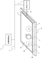
- FIG. 2 shows an example of the configuration of the merchandise management system according to the present embodiment.
- This merchandise management system is a system that sequentially monitors the merchandise displayed on merchandise display shelves in stores, etc., determines the presence or absence of merchandise on the merchandise display shelves, and performs processing such as display related to the display status is there.
- a merchandise management system that manages merchandise will be described.
- the merchandise management system is not limited to merchandise, and may be an article management system that manages other articles that can be detected in the present embodiment.
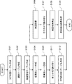
- the product management system includes a store management device 1, an RFID reader 7, a product display shelf 8, a tag antenna unit 50 including a reader transmission line 4 and an RFID tag 5, and a metal foil sheet. 9 is provided.
- a plurality of product display shelves 8 may be provided, a plurality of reader transmission lines 4 (tag antenna units 50) may be provided on the product display shelves 8, and a plurality of reader transmission lines 4 may be provided.
- a metal foil sheet 9 may be provided.
- the RFID reader 7 and the store management apparatus 1 are connected via a communication network 3 such as a LAN so that data can be transmitted and received.
- the RFID reader 7 and the reader transmission line 4 are connected via a high-frequency cable 3a.
- the tag antenna unit 50 is disposed in the entire product display shelf 8 in the product displayable area.
- the tag antenna unit 50 includes a reader transmission line 4 and an RFID tag 5, and a plurality of RFID tags 5 are fixedly arranged in advance on the reader transmission line 4 corresponding to at least a product displayable area.
- the entire upper surface of the reader transmission line 4 (tag antenna unit 50) corresponds to the product displayable area 2b.
- the product displayable area 2b is a placeable area in which the product 2 can be placed, and includes a display position (placement area) 2a assigned to display (place) the product 2 by shelf allocation.
- the display position 2a includes at least one RFID tag 5 fixedly arranged in advance.
- the display position 2a includes a place (coordinates) where the product is arranged, and may further include an area necessary for arranging the product.
- the product display shelf 8 may be provided with an alignment mechanism, and alignment may be performed when the tag antenna unit 50 (reader transmission line 4) is installed.
- the alignment mechanism for example, a mark or the like indicating the arrangement position of the tag antenna unit 50 may be displayed on the commodity display shelf 8.
- the tag antenna unit 50 may be used as a substitute for the shelf board without providing the product display shelf 8.
- the reader transmission line 4 is composed of a transmission line that is matched and terminated.
- the transmission line is open to the RFID tag 5, and electromagnetic waves such as a stripline structure, a microstrip structure, a coplanar line, and a slot line, where at least the metal foil sheet 9 is regarded as a part of the ground conductor, are transmitted.
- This is an open transmission line having a structure that oozes out as a near field in a space where the surrounding RFID tag 5 exists.
- 3A is an example in which the reader transmission line 4 is configured by a microstrip line
- FIG. 3B is an example in which the reader transmission line 4 is configured by two parallel lines.
- the RFID reader 7 and the distributor 46 are connected by the high frequency cable 3a, and the distributor 46 distributes the signal of the high frequency cable 3a to a plurality of strip conductors (microstrip lines) 43.
- a plurality of strip conductors 43 extend in parallel on the spacer 42 which is a dielectric layer, and a ground plane 41 is formed on the entire surface under the spacer 42.
- the RFID reader 7 and the distributor 46 are connected by the high frequency cable 3a, and the distributor 46 distributes the signal of the high frequency cable 3a to the plurality of parallel two lines 45.
- the plurality of parallel two lines 45 are arranged to extend in parallel on the spacer 42 which is a dielectric layer.
- the distributor 46 may have functions such as impedance conversion and balance-unbalance conversion.
- FIGS. 4 is a perspective view of the tag antenna unit 50
- FIG. 5 is a top view thereof
- FIG. 6 is a front sectional view and a side sectional view thereof.
- the reader transmission line 4 of the tag antenna unit 50 is configured by a microstrip line.
- a spacer 42 is formed on the entire ground plane 41 which is the size of the tag antenna unit 50.
- a plurality of strip conductors 43 are formed so as to extend in parallel at predetermined intervals from one end to the other end on the spacer 42.
- a spacer 44 is formed on the entire spacer 42 and the strip conductor 43.
- the spacers 42 and 44 are made of a dielectric material.
- a plurality of RFID tags 5 are arranged on the spacer 44 so as to fill the upper surface region of the spacer 44 with a certain pattern. By arranging a plurality of RFID tags 5 in a uniform pattern, it is possible to deal with various product arrangements by shelving.
- the size of the RFID tag 5 is smaller than the size of the display position 2a, that is, the product size (bottom surface) in contact with the arrangement surface when the product 2 is arranged. Is preferred. Further, the interval W between the RFID tags 5 shown in the enlarged view of FIG. 5 is preferably narrower than the size of the display position 2a, that is, the product size in contact with the arrangement surface when the product is arranged, and more preferably, the display position 2a. Is less than half of the size. In this case, two or more RFID tags 5 can be included in the display position 2a. Alternatively, there is always an RFID tag that is completely contained in the area of the display position 2a.
- the interval W is a distance between two adjacent RFID tags 5, for example, a distance from the center of the RFID tag 5 to the center of the adjacent RFID tag 5 as shown in the enlarged view of FIG. 5.
- the arrangement pattern columns in which the RFID tags 5 are arranged at predetermined intervals are shifted from one column to another. That is, as shown in the enlarged view of FIG. 5, a plurality of columns 51 of RFID tags 5 arranged at a predetermined interval W are arranged in the extending direction of the strip conductors 43 (column direction, for example, the horizontal direction of the shelf). Then, in correspondence with the position between the RFID tags adjacent in the column direction (the left-right direction of the shelf), the RFID tags in the adjacent column (the depth direction of the shelf) are shifted so as to be positioned. By displacing each column, the interval (distance) between adjacent RFID tags increases between columns (in the depth direction of the shelf), so that electromagnetic field coupling can be suppressed.
- the capacitance characteristics can be set in the RFID tag 5 by forming the ground plane 41, the RFID tag 5 can be reduced in size. Thereby, more RFID tags 5 can be read by one strip conductor 43.
- a protective material that protects the ground plane 41 may be formed under the ground plane 41.
- the two adjacent strip conductors 43 are preferably differential transmission lines for transmitting differential signals.
- an in-phase signal is transmitted to the two strip conductors 43, there is a possibility that the RFID tag 5 cannot be read because the electric field between the strip conductors 43 is zero or the electric field is so weak that the tag cannot be read. Therefore, by using a differential strip conductor that transmits a differential signal, the above-described region cannot be formed, and thus the RFID tag 5 can be read reliably.
- the RFID tag 5 transmits / receives data to / from the reader transmission line 4 by a UHF band signal.
- 2 reads the management information including the signal strength information of the response signal output from the RFID tag 5 and the tag information of the RFID tag 5 via the reader transmission line 4.
- the spacers 44 setting the distance L 2 between the distance of the RFID tag 5 and item 2 L 1 and RFID tag 5 and the reader transmission line 4. For example, the distance L 1 ⁇ the distance L 2 is set. Incidentally, if set relationship between the distance L 1 and the distance L 2 may not be provided a spacer 44.
- the RFID tag 5 has a tag antenna.
- the RFID tag 5 is arranged at the position as described above, so that the tag antenna and the product 2 are electromagnetically coupled in a state where the product 2 is placed at the display position 2a.
- the reader transmission line 4 is a transmission line that is matched and terminated.
- the reader transmission line 4 is arranged at a position where the tag antenna and the tag antenna are electromagnetically coupled to each other.
- the RFID tag 5 is placed. It is possible to transmit and receive wireless signals to and from.
- the RFID reader 7 supplies power to the RFID tag 5 by radio waves via the reader transmission line 4 and receives a radio signal transmitted by the RFID tag 5 via the reader transmission line 4. Information is received from the received radio signal. And a transmission / reception unit for transmitting the information transmitted by the RFID tag 5 to the store management apparatus 1.
- the RFID reader 7 may read the RFID tag 5 at a timing when receiving an instruction from the store management device 1 or may read the RFID tag 5 at a timing determined by the RFID reader 7 itself. For example, the RFID reader 7 reads the RFID tag 5 at any given time interval such as 1 second.
- the RFID reader 7 and each RFID tag 5 are in a communicable state due to electromagnetic coupling by the near field with the reader transmission line 4. Is placed on the position where the RFID tag 5 exists, the communication between the RFID tag 5 and the RFID reader 7 changes the electromagnetic coupling state by the dielectric and metal of the product 2 itself, and the RFID tag Thus, the information sent from 5 to the RFID reader 7 is blocked and the signal intensity is reduced. The fact that there is a product 2 at the corresponding position with this information blockage or signal strength reduction is sent from the RFID reader 7 (reader transmission line 4) to the store management device 1 to know the state of the product on the product display shelf 8. be able to.
- the configuration (product presence / absence detection unit) and the detection principle for realizing the product presence / absence detection method according to the present embodiment using the RFID reader 7, the reader transmission line 4 and the RFID tag 5 will be described in detail.
- the RFID reader 7, the reader transmission line 4, and the RFID tag 5 constitute a product presence / absence detection unit
- the store management device 1 product presence / absence determination unit
- FIG. 7 shows a three-side view of the tag antenna unit 50 including the reader transmission line 4 and the RFID tag 5 using the microstrip line structure according to the present embodiment.
- FIG. 7 the figure which expanded the area
- an example will be described in which an RFID tag is disposed immediately above a strip line and one product is disposed on one RFID tag.
- the reader transmission line 4 in FIG. 7 is a traveling wave transmission line for a reader using a microstrip line, which is a kind of open transmission line, as in FIGS.
- the reader transmission line 4 has a spacer 42 that is a dielectric layer, a strip conductor 43 is formed on the upper surface of the spacer 42, and a ground plane 41 is formed on the lower surface of the spacer 42.
- the RFID tag 5 is installed above the strip conductor 43. Further, the commodity 2 is placed in the display position 2a where the RFID tag 5 above the RFID tag 5 is covered.
- the RFID tag 5 includes an RFID chip 201 and a tag antenna 202.
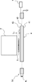
- FIG. 8 shows a front view for explaining the commodity presence / absence detecting unit including the reader transmission line 4, the RFID tag 5, and the RFID reader 7 according to the present embodiment.
- FIG. 8 shows an enlarged view of a region where one product 2 is placed in the tag antenna unit 50 as in FIG.
- the reader transmission line 4 in FIG. 8 has a strip conductor 43 formed on the upper surface of the spacer 42 and a ground plane 41 formed on the lower surface of the spacer 42.
- One end of the strip conductor 43 and the ground plane 41 are connected via a matching termination resistor Rt. With this connection, the reader transmission line 4 is terminated with matching.
- the RFID reader 7 is connected to the other end of the strip conductor 43.
- item 2 is arranged at a distance is a first distance L 1 position between the tag antenna 202 of the RFID tag 5.
- Tag antenna 202 of the RFID tag 5 is arranged at a distance is a second distance L 2 position between the strip conductor 43.
- FIG. 8 only the distance relationship between the product 2, the tag antenna 202, and the strip conductor 43 is shown.
- the thickness of the plastic plate can be used. That is, it is possible to built-in RFID tag 5 to the plastic plate, to secure the first distance L 1 by forming a sheet embedded RFID tag by the plastic plate.
- the spacer 44 by inserting the spacer 44 under the RFID tag 5, it is possible to provide a table for supporting the tag and to secure the second distance L2.
- the above technique is a form for securing a first distance L 1 and the second distance L 2, it is also possible to use other techniques.
- the strip conductor 43, and the tag antenna 202 while remaining in the same plane, or may be the distance L 2 apart in a plane.
- the product 2 is located above the tag antenna 202 of the RFID tag 5 and the distance is the first distance L 1. Placed in. Furthermore, the strip conductors 43 connected to the RFID reader 7, a lower portion of the RFID tag 5, sight distance between the strip conductor 43 and the tag antenna 202 is disposed apart by a second distance L 2 . In this way, in the product management system, the product 2 is arranged outside the region sandwiched between the reader transmission line 4 (strip conductor 43) and the RFID tag 5. Therefore, the line of sight between the reader transmission line 4 and the RFID tag 5 is not blocked by the product 2.
- product 2 and a second is expected distance between the first distance L 1 and the tag antenna 202 between the tag antenna 202 and the reader transmission line 4 (strip conductor 43) it is desirable to adjust the distance L 2.
- the coupling coefficient k 2 between the merchandise 2 and the tag antenna 202 and the tag antenna 202 and the reader transmission line 4 (strip) are adjusted by adjusting the first distance L 1 and the second distance L 2. It is desirable to adjust the coupling coefficient k 1 with the conductor 43).
- the signal strength between the tag antenna 202 and the reader transmission line 4 is changed according to the coupling coefficient k 2 that changes depending on the presence / absence of the product 2, and the presence / absence of the product 2 is determined by the change in the signal strength. Judging.
- the coupling coefficient indicating the strength of the electromagnetic coupling can be evaluated relatively easily by an electromagnetic simulator.
- the electromagnetic field coupling when the wavelength of the radio signal between the tag antenna 202 and the reader transmission line 4 is ⁇ , the distance from the wave source (for example, the transmission line) is ⁇ / 2 ⁇ ( ⁇ is the circularity ratio).
- Nearer region is reactive near field, distance is longer than ⁇ / 2 ⁇ and nearer than ⁇ is near radial field, and these two regions are combined and near. This is called the near-field region.
- the electromagnetic field has a complex aspect, and there exists a non-negligible intensity ratio between the quasi-electrostatic magnetic field, the induction electromagnetic field, and the radiated electromagnetic field, and the resultant electromagnetic field vector is also spatial.
- Changes in time variously.
- the wave source is a minute dipole antenna
- the electric field E [V / m] and the magnetic field H [A / m] formed by this antenna are indicated by a spherical coordinate system (r, ⁇ , ⁇ ) and a phasor display. It can be expressed by the following formulas (1) to (4).
- the charge stored in the minute dipole antenna is q [C]
- the length of the antenna is l [m]
- the wavelength is ⁇ [m]
- from the wave source to the observation point was set to r [m].
- ⁇ is a circular constant
- ⁇ is a dielectric constant
- ⁇ is a magnetic permeability.
- the term proportional to 1 / r 3 is a quasi-electrostatic magnetic field
- the term proportional to 1 / r 2 is an induction electromagnetic field
- the term proportional to 1 / r is radiated.
- the electromagnetic field is shown. Since these electromagnetic field components have different dependencies on the distance r, the relative strength changes depending on the distance r.
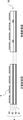
- FIG. 9 shows a table illustrating the quasi-electrostatic field in Figure 9 in a field E theta, induced electric field, the dependence on the distance r normalized by the wavelength ⁇ for the relative intensity of the radiation field.
- the second row of the table shown in FIG. 9 shows the distance converted with a free space wavelength of 950 MHz, which is almost the same as the frequency of UHF (Ultra High Frequency) band RFID permitted by the Domestic Radio Law.
- UHF Ultra High Frequency
- each electric field strength decreases and each component ratio also changes.
- the electric field strength increases in the order of quasi-electrostatic field, induction field, and radiation field
- the field strength decreases in order of quasi-electrostatic field, induction field, and radiation field.
- the contribution of the quasi-electrostatic field and the induced electric field is extremely small in the region where r> ⁇ , and only the radiated electric field component is present in the far field where r> 2 ⁇ .
- the contribution of the quasi-electrostatic field and the induced electric field remains sufficiently in the region of r ⁇ , and the quasi-electrostatic field and the induced electric field make a large contribution in the reactive near field of r ⁇ / 2 ⁇ .
- the far-field (r >> ⁇ / 2 ⁇ ) radiation field has only the ⁇ direction component, whereas the quasi-electrostatic magnetic field and the induction electromagnetic field are ⁇ In addition to the direction component, it has an r-direction component and a ⁇ -direction component, and has components in various directions.
- the quasi-electrostatic field and the induced electromagnetic field that remain in the vicinity of the antenna (transmission line) are dominant in the reactive near field.
- the absolute electromagnetic field strength is also strong. In the near field of radiation, in general, the absolute electromagnetic field strength becomes weaker as the distance from the wave source becomes longer.
- the relative strength of the quasi-electrostatic magnetic field and the induction electromagnetic field rapidly decreases as the distance from the wave source increases.
- the relative strength of the radiated electromagnetic field is increased with respect to other electromagnetic fields.
- a quasi-electrostatic magnetic field and an induction electromagnetic field exist in the near field, and these electromagnetic fields cause coupling between the reader transmission line 4 and the tag antenna 202 and coupling between the tag antenna 202 and the product 2. .
- the distance r between the reader antenna corresponding to the reader transmission line 4 and the tag antenna satisfies the relationship of r> ⁇ . Is used.
- a resonant antenna typified by a patch antenna is often used as the reader antenna.
- the electromagnetic field strength varies greatly depending on the location due to the standing wave in the resonant antenna. For example, the amplitude is the largest near the antinode of the standing wave, and the amplitude is 0 at the node of the standing wave.
- the signal from the reader antenna is near the midpoint of the standing wave in the reader antenna. Can not be received by the tag antenna, or the received signal strength becomes extremely weak. That is, an insensitive area is created, which may hinder use.
- a coupling circuit can be formed by electromagnetic coupling between antennas through a quasi-electrostatic magnetic field and an induction electromagnetic field that exist in the near field of r ⁇ , and more preferably in the reactive near field of r ⁇ / 2 ⁇ . .
- a wide space is not required between the RFID reader and the RFID tag according to the conditions.
- a resonant antenna is simply used in place of the reader transmission line 4, a dead zone is created, which may hinder use.
- the reader transmission line 4 connected to the RFID reader 7 is constituted by a transmission line that is matched and terminated, and the transmission line and the tag antenna 202 of the RFID tag 5 are electromagnetic fields.
- the RFID tag 5 is arranged so as to be coupled.
- the reader transmission line 4 is mainly transmitted through a quasi-electrostatic magnetic field and an induction electromagnetic field generated around the transmission line.
- the tag antenna 202 is electromagnetically coupled to form a coupling circuit. That is, it can be said that the transmission line is used as a traveling wave antenna operating in the near field. With this configuration, a large space is not required between the reader transmission line 4 and the RFID tag 5.
- the communication between the reader transmission line 4 and the tag antenna 202 is performed at a short distance through the coupling circuit, there is no human or the like between the occurrence of the multipath phenomenon and the place where the reader transmission line 4 and the product 2 are arranged. It is possible to suppress erroneous detection due to a thing entering. Furthermore, since a transmission line terminated with matching is used as the reader transmission line 4, the main component of the electromagnetic wave propagating through the antenna does not generate a standing wave but propagates as a traveling wave to the matching end.
- the fact that no standing wave is generated means that the standing wave is sufficiently small, and usually the standing wave ratio is a value of 2 or less.
- the electromagnetic field distribution in such a transmission line can be utilized.
- the electromagnetic field formed in the space around the line has a relatively small radiated electromagnetic field, and an electrostatic magnetic field and an induction electromagnetic field are main components.
- the electromagnetic field intensity of the electrostatic magnetic field and the induction electromagnetic field is stronger than the intensity of the radiated electromagnetic field, and the electromagnetic field intensity with which the RFID tag 5 can be obtained becomes strong even when the reader is operating with the same output. In other words, it is possible to prevent the radiation electromagnetic field from deteriorating the surrounding electromagnetic environment while ensuring the operation of the tag.
- the electromagnetic field distribution in the vicinity of the antenna is very uneven according to the distribution of the standing wave inside the antenna.
- the area where the product 2 can be managed needs to be limited.
- a reader transmission line made up of a matched-terminated transmission line described in the present embodiment there is no portion that does not change in the electromagnetic field distribution, such as a standing wave node, even in the vicinity of the transmission line. , It is possible to obtain the required signal strength everywhere. Therefore, even in the near field, the non-uniformity of the electromagnetic field along the transmission line (antenna) is small, and it is difficult to generate an area where the tag information of the RFID tag 5 cannot be read. That is, the degree of freedom of arrangement of the reader transmission line 4 and the tag antenna 202 is improved.
- the detection unit extends the transmission line regardless of the wavelength within a range in which the strength of the quasi-electrostatic magnetic field and the induction electromagnetic field generated around the transmission line is sufficiently large to operate the RFID tag 5, thereby extending the cover area. Can be taken widely. That is, in the product management system according to the present embodiment, by using the above transmission line, the radiation loss of power is suppressed and the cover area can be easily expanded.
- the transmission line here is basically a transmission line for the purpose of transmitting electromagnetic waves in the longitudinal direction of the line while suppressing radiation, so that the RFID tag 5 can be electromagnetically coupled to the RFID tag 5.
- the open space is not completely covered with metal. Examples include balanced two-wire transmission lines and similar transmission lines, transmission lines such as microstrip lines, coplanar lines, and slot lines, and grounded coplanar lines and triplate lines that are modifications of these transmission lines.
- the RFID tag 5 may be disposed between the ground conductor and the strip conductor, and an appropriate open structure may be provided in the ground conductor.
- a planar shape (two-dimensional) that transmits signals by changing the electromagnetic field propagating in the gap region sandwiched between the mesh-like conductor portion and the sheet-like conductor portion and the near-field leaching region outside the mesh-like conductor portion.
- Antennas can also be used depending on the conditions.
- a shielded transmission line that does not generate such an electromagnetic field around the transmission line, such as a coaxial cable or a waveguide that shields the periphery of the transmission line, cannot be used.
- crank line that obtains a constant radiated electromagnetic field strength by designing a crank shape with the intention of radiating electromagnetic waves from an open transmission line or by actively using higher-order modes.
- a traveling wave antenna for electromagnetic radiation in the far field using an antenna, a meander line antenna, a leaky coaxial cable or the like is different from the transmission line used in the product management system according to the present embodiment.
- These traveling wave antennas emit strong electromagnetic waves preferentially from crank-shaped portions and slots that are periodically provided with a size of the order of a wavelength, generally 1/10 or more of the wavelength. Similar to the resonant antenna, there is a drawback that the strength of the electromagnetic field varies greatly depending on the location.
- the allocated frequency is different in each country in the world, and it is distributed in a band of about 860 to 960 MHz. This is a wide band of about 10% as a specific band, and is a resonant antenna. Resonant point design and crank, meander, and slot periods require significant changes.
- a transmission line having an extremely wide band is originally used, so that the same antenna can be used as the reader transmission line 4 without any particular change.
- the display position 2a for placing the product 2 near the RFID tag 5 is provided so that the product 2 and the tag antenna 202 of the RFID tag 5 are electromagnetically coupled. It is done. Accordingly, since the product 2 and the tag antenna 202 form a coupling circuit when the product 2 is present, the resonance frequency of the tag antenna 202 changes or the feed point impedance of the tag antenna 202 is compared with the case where the product 2 is not present. Or change. Since the tag antenna 202 resonates at the frequency of the signal used for communication in free space, the feed point impedance is adjusted, and the reception sensitivity is maximized, the above change lowers the reception sensitivity.
- the operation of the tag antenna 202 when sending a reflected signal to the RFID reader 7 is also adversely affected.
- the power reception sensitivity with respect to the signal used for communication falls.
- the transmission output of the signal reflected by the RFID tag 5 also decreases. Therefore, the RFID tag 5 cannot receive a signal from the RFID reader 7, or the signal receiving intensity is low, and the tag cannot be provided with sufficient operating power, or the tag cannot generate a reflected electromagnetic field with sufficient strength.
- the RFID reader 7 cannot read the tag information of the RFID tag 5.
- the intensity and phase of the reflected electromagnetic field reaching the RFID reader 7 change greatly with changes in the resonance frequency of the tag.
- the tag information cannot be read, or the intensity of the reflected electromagnetic field from the RFID tag 5 changes greatly compared to the case where the product 2 is not present.
- the presence of the product 2 can be detected. That is, as a result of the change in the operational characteristics of the tag antenna 202 depending on the presence or absence of the product 2, the RFID reader 7 can detect the intensity change of the reflected signal from the RFID tag 5, and the detection result can be used to implement the present invention.
- the product management system according to the embodiment can detect the presence or absence of a product.
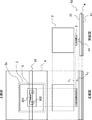
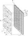
- FIGS. 10 is a perspective view of the tag antenna unit 50 and the metal foil sheet 9
- FIG. 11 is a top view thereof
- FIG. 12 is a front sectional view and a side sectional view thereof
- FIG. 13 is a cross-sectional view of the metal foil sheet 9.
- a large number of RFID tags are arranged in advance on the reader transmission line in order to manage the product easily even if the arrangement of the product is changed.
- the reading speed becomes slow.
- unnecessary portions are further covered with a metal foil sheet, and a tag that does not need to be read is covered and cannot be read.
- a metal foil sheet 9 is placed on the tag antenna unit 50.
- the RFID tag 5 is disposed on the reader transmission line 4 in advance, and the metal foil sheet 9 is disposed on the RFID tag 5.
- the metal foil sheet 9 becomes an upper surface ground for the strip conductor, covers an RFID tag that does not need to be read, and prevents the tag from being read, thereby suppressing deterioration in reading speed.
- the metal foil sheet 9 is electromagnetically coupled to an RFID tag that does not need to be read, thereby reducing the signal strength, thereby stopping (invalidating) the operation of the RFID tag, and the signal of the RFID tag that requires reading.
- the operation of the RFID tag is maintained (activated) without affecting the strength. Further, since the upper surface ground is formed on the strip conductor, the emission of electromagnetic waves from the upper surface is suppressed. Therefore, the radiation loss of the transmission line is reduced and the transmission line can be lengthened. In addition, effects such as suppression of electromagnetic interference with other devices, reduction of noise, and reduction of influence on the human body can be obtained.
- the metal foil sheet 9 is a sheet-like metal member (metal sheet), and further has an opening (opening window) 9a at the position of the RFID tag that needs to be read. .
- the product is arranged on the metal foil sheet 9, so that the upper surface of the metal foil sheet 9 becomes the product displayable region 2b.
- the size and shape of the metal foil sheet 9 is equal to or larger than the size covering the RFID tag 5 in order to stop the response operation of the RFID tag 5 that does not require reading. If it is smaller than the size of the RFID tag 5, the response operation of the RFID tag 5 may not be stopped.
- the metal foil sheet 9 is desirably a size that can cover the size of the display position 2a of at least one product, that is, the area occupied by one type of product on the shelf. Further, the metal foil sheet 9 selectively disables or activates the operation from all the RFID tags 5, so that the size covers all the RFID tags 5, that is, the product displayable region 2b or the reader transmission line 4 (tag It is desirable that the size is substantially the same as the antenna unit 50).
- the opening (opening window) 9a is formed at a position corresponding to the RFID tag 5 at the product display position 2a.
- the opening 9a is at least larger in size and shape than the RFID tag 5 in order to enable the operation of the RFID tag 5 positioned below when the metal foil sheet 9 is disposed.
- the opening 9 a is substantially the same size as the RFID tag 5 and has the same square shape as the RFID tag 5.
- the metal foil sheet 9 is a metal foil such as an aluminum foil, and a conductor is attached to a resin sheet such as PET (polyethylene terephthalate) or paper such as synthetic paper.
- the conductor may be aluminum, copper, carbon, ITO (indium tin oxide), or the like.
- the metal foil sheet 9 has a conductor layer 92 formed on the cover layer 91, a resin sheet 93 formed on the conductor layer 92, and a cover on the resin sheet 93.
- Layer 94 is formed.
- the thickness of the metal foil sheet 9 is preferably equal to or greater than the skin thickness (thickness that provides the skin effect).
- the conductor layer 92 is a good conductor metal, the thickness is preferably 2 microns or more.
- the opening 9a is formed by removing the cover layer 91 to the cover layer 94, but at least only the conductor layer 92 may be removed.
- the metal foil sheet 9 can be formed by a Roll-to-Roll process such as an aluminum sheet for food packaging.
- the conductor layer of the metal foil sheet 9 is formed by vapor deposition, sputtering, plating, rolling, or the like.
- the opening 9a is formed by etching a metal layer, cutting a sheet, or the like.
- the reader transmission line 4 includes a ground plane 41, a spacer 42, a strip conductor 43, and a spacer 44.
- the metal foil sheet 9 and the RFID tag 5 are in close contact with each other (the better there is no gap to the extent that the reader cannot read the tag). Further, the metal foil sheet 9 and the strip conductor are spaced apart by the spacer 44 to form a strip line.
- the spacer 44 can reduce the influence of the ground on the RFID tag. However, an increase in capacity due to the ground may be used to reduce the size of the RFID tag.
- a protective material for protecting the RFID tag 5 may be disposed on the RFID tag 5.
- the metal foil sheet 9 may also function as the protective material.
- the alignment mechanism for example, a mark or the like indicating the arrangement position of the metal foil sheet 9 may be displayed on the tag antenna unit 50.
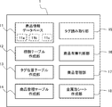
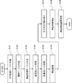
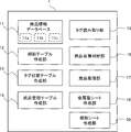
- the store management device 1 includes a product information database 11, a shelf allocation table creation unit 12, a tag position table creation unit 13, a product management table creation unit 14, a tag reading unit 15, and a product presence / absence determination unit 16.
- the product management unit 17 and the metal foil sheet creation unit 18 are provided.
- each of these blocks will be described as a function of the store management apparatus 1, but some / all of these blocks are provided in the RFID reader 7, and necessary information is sent from the RFID reader 7 to the store management apparatus 1. You may send it.
- the configuration of this functional block is an example, and other configurations may be used as long as a product management process according to the present embodiment described later can be realized.
- the store management device 1 is composed of a general computer device (server device).
- the store management device 1 includes a central processing unit (CPU), a storage device such as a memory and a hard disk device, an input device such as a keyboard, a display device such as a liquid crystal display, and a communication unit connected to the communication network 3.
- the storage device stores a product management program for executing the product management processing according to the present embodiment, and each functional block is realized by the CPU executing this program.
- the store management device 1 is not limited to a single computer, and may be configured by a plurality of computers.
- Non-transitory computer readable media include various types of tangible storage media (tangible storage medium). Examples of non-transitory computer-readable media include magnetic recording media (eg flexible disks, magnetic tapes, hard disk drives), magneto-optical recording media (eg magneto-optical discs), CD-ROMs (Read Only Memory), CD-Rs, CD-R / W, semiconductor memory (for example, mask ROM, PROM (Programmable ROM), EPROM (Erasable ROM), flash ROM, RAM (random access memory)) are included.
- the program may also be supplied to the computer by various types of temporary computer-readable media. Examples of transitory computer readable media include electrical signals, optical signals, and electromagnetic waves.
- the temporary computer-readable medium can supply the program to the computer via a wired communication path such as an electric wire and an optical fiber, or a wireless communication path.
- the product information database 11 stores product information related to the product 2 displayed on the product display shelf 8.
- the product information database 11 stores a shelf allocation table 11a, a tag position table 11b, and a product management table 11c. That is, the product information database 11 includes a shelf allocation table storage unit that stores the shelf allocation table 11a, a tag location table storage unit that stores the tag location table 11b, and a product management table storage unit that stores the product management table 11c. It can be said.
- FIG. 15 shows an example of the shelf allocation table 11a
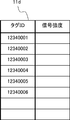
- FIG. 16 shows an example of the tag position table 11b
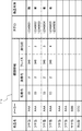
- FIG. 17 shows an example of the product management table 11c.
- the shelf allocation table 11a is an example of an article position table, and is a table that stores display position information (shelf allocation information) on a product shelf in association with each product information. For example, as shown in FIG. 15, the shelf allocation table 11a associates product names, manufacturers, product sizes, and shelf allocation information.
- the product name, manufacturer, and product size are identification information (product information) for identifying the product arranged on the shelf.
- the product name is the sales name of the product and is product specifying information for specifying the product. If there are different products (taste, size, etc.) with the same sales name, they may be further classified by taste.
- the manufacturer is the name of the manufacturer or distributor of the product, and is also group information for associating different products. Not only the manufacturer but also other group information such as the type of food.
- the product size is the size of the outer shape of the product, and includes, for example, the width, height, and depth.
- the product size is also an arrangement size that occupies an area on the shelf when arranged.
- the size of the display position (arrangement area) of the product can be specified by the width of the product (the length in the left-right direction of the shelf) and the depth (the length from the front of the shelf to the back direction).
- the shelf allocation information is a display position (arrangement position or allocation position) on a shelf (product displayable area 2b) allocated for each product by the shelf allocation, and includes, for example, a shelf number, a column number, a face, and a depth number. It is.
- the shelf number (unit number) is information for identifying a product display shelf (gondola) set in the store.
- the column number is information for identifying the column of the shelf provided in the product display shelf (gondola).
- the face is information for identifying an array position (face position) which is the position of the forefront of the shelf. In addition to the face position of the product, the number of faces indicating the number of faces (how many rows) of the same product may be used.
- the depth number is information indicating the number of the same product to be arranged from the front to the back on the face (column) of the shelf. Since the shelf allocation information specifies how many and where the products are arranged on which shelf, the entire arrangement area of one product can be specified by the shelf allocation information and the product size.
- the first data example in FIG. 15 shows that the product of the manufacturer “AAA” and the product name “tuna can” has a product size of width 70 mm ⁇ height 30 mm ⁇ depth 70 mm. It is shown that 6 depths are allocated to the second 340th column (face).
- the tag position table 11b is a table that stores display position information on the RFID tag shelf in association with each tag ID of the RFID tag.
- the tag ID (tag information) is identification information assigned to each RFID tag 5 and stored in advance in the RFID tag 5.
- the position information on the shelf of the RFID tag is a fixed position fixed in advance on the shelf (product displayable area 2b), and includes, for example, a shelf number, a column number, a face position, and a depth position.
- the shelf number unit number
- the column number identifies the shelf row
- the face position identifies the shelf array location
- the depth indicates the position in the depth direction from the front of the face (column).
- the first data example in FIG. 16 shows that the RFID tag with the tag ID “1234341” is fixedly arranged at a position of 40 mm from the front in the 340th column (face) of the second shelf of the shelf 03. ing.
- the merchandise management table 11c is an example of an article management table, and is a table that associates RFID tags for each merchandise information and stores the status of merchandise. In addition, the position of the product is also associated as necessary. Since the position of the product may be grasped from the shelf allocation table 11a, it may be omitted.
- the product management table 11c associates product names, manufacturers, shelf allocation information (position information), tag IDs, and product presence / absence.
- the product name and manufacturer are product identification information and correspond to the product name and manufacturer included in the shelf allocation table 11a.
- the shelf allocation information is position information (arrangement information) of each product and corresponds to the shelf allocation information included in the shelf allocation table 11a. For example, like the shelf allocation information in FIG.
- the shelf allocation information includes a shelf number, a column number, a face, and a depth order.
- the number of depths is used in order to divide a plurality of products into shelves, but in FIG. 13, in order to identify each product, the depth order is the order from the front of the face (column) to the depth direction.
- the tag ID is identification information of the RFID tag, and corresponds to the tag ID included in the tag position table 11b.
- Product presence / absence is product display (arrangement) state information indicating whether or not a product is displayed (arranged) on the RFID tag 5 and indicates a detection result of the RFID tag 5.
- the first data example in FIG. 17 shows that the product of the manufacturer “AAA” and the product name “tuna can” is shelf-ordered in depth order 1 in the 340th column (face) of the second shelf of the shelf 03.
- the corresponding product corresponds to the position of the RFID tag with the tag ID “12340001”, and the detection result of the RFID tag with the tag ID “12340001” indicates that this product is not currently displayed at this position.
- the second data example in FIG. 13 is the second in depth order in the 340th column (face) of the second shelf of the shelf 03 among the products of the manufacturer “AAA” and the product name “tuna can”.
- the products that are shelved with the ID correspond to the positions of the two RFID tags with the tag IDs “12340002” and “12340002”, and this position is currently determined based on the detection result of the RFID tags with the tag IDs “12340001” and “12340001”. Shows that this product is displayed.
- the shelf allocation table creation unit 12 creates a shelf allocation table 11 a and stores the created shelf allocation table 11 a in the product information database 11.
- the shelf allocation table creation unit 12 includes general shelf allocation software (a shelf allocation program), and creates the shelf allocation table 11a by executing the shelf allocation software.
- the shelf allocation table creation unit 12 receives product information such as product name, manufacturer, and product size from the product master data, and stores the position and size of the product display shelf (gondola) and product display shelf from the fixture master data.
- the fixture information is input, and the shelf allocation table 11a is created by dividing the shelf according to user operation, sales tendency, season, campaign, and the like.
- the shelf allocation table 11a may be input to the store management device 1 from the outside without being created by the store management device 1.
- the retail headquarters that centrally manages a plurality of retail stores may create the shelf allocation table 11a with the shelf allocation software and input it to the store management device 1 of each retail store.
- the shelf allocation table creation unit 12 may be a shelf allocation table acquisition unit that acquires (inputs) the shelf allocation table 11 a from the outside and stores the acquired shelf allocation table 11 a in the product information database 11.
- the tag position table creation unit 13 creates a tag position table 11 b and stores the created tag position table 11 b in the product information database 11.
- the tag position table creating unit 13 receives the tag ID and position information of the RFID tag arranged on the shelf, and creates the tag position table 11b by associating the tag ID with the position information.
- the position information on the shelf is displayed in the area where the RFID tag is arranged, the tag ID is displayed on the RFID tag, and the position information and the tag ID of the RFID tag are visually read by the user.
- the tag ID may be input to the store management apparatus 1.
- a bar code indicating position information on the shelf is displayed in the area where the RFID tag is arranged, and a bar code indicating the tag ID is displayed on the RFID tag.
- the bar code indicates the position information and tag ID of the RFID tag.
- the position information and the tag ID that are sequentially read by the reader may be input to the store management apparatus 1.
- the position of the RFID tag and the tag ID may be acquired by photographing a shelf on which the RFID tag is arranged with a camera or the like and performing image processing.
- the tag position table 11b may be input to the store management device 1 from the outside without being created by the store management device 1.
- the tag position table creation unit 13 may be a tag position table acquisition unit that acquires (inputs) the tag position table 11 b corresponding to the arrangement of the RFID tags and stores the acquired tag position table 11 b in the product information database 11.
- the product management table creation unit 14 creates the product management table 11c based on the shelf allocation table 11a and the tag position table 11b, that is, according to the relationship between the shelf allocation information in the shelf allocation table 11a and the position information in the tag location table 11b.
- the created product management table 11 c is stored in the product information database 11.
- the product management table creation unit 14 calculates an area (arrangement area) of the display position of the product from the product size and the shelf allocation information in the shelf allocation table 11a. Then, the merchandise management table creation unit 14 determines RFID tags that exist in the calculated merchandise display position area from the tag position information in the tag position table 11b. Further, the product management table creating unit 14 creates the product management table 11c by associating the determined RFID tag with the product.
- the product management table 11c may be created based on the association between the product inputted from the outside and the RFID tag without automatically creating the product management table 11c from the shelf allocation table 11a and the tag position table 11b. .
- position information is displayed in the area on the shelf, product information is displayed on the product, a tag ID is displayed on the RFID tag, and the user can visually check the position information, product information, and tag ID of the product.
- the read position information, the product information, and the tag ID may be input to the store management device 1 to create the product management table 11c.
- a barcode indicating position information is displayed in the area on the shelf, a barcode indicating product information (for example, JAN code) is displayed on the product, and a barcode indicating tag ID is displayed on the RFID tag.
- the product position information, the product information, and the tag ID may be sequentially read by a barcode reader, and the read position information, product information, and tag ID may be input to the store management apparatus 1 to create the product management table 11c.
- the tag reading unit 15 reads the RFID tag 5 on the reader transmission line 4 via the RFID reader 7. For example, the tag reading unit 15 transmits a batch read command for reading all tags to the RFID reader 7, and the RFID reader 7 reads all the RFID tags 5 on the reader transmission line 4 at a time. In the present embodiment, since the metal foil sheet 9 is arranged on the RFID tag 5, only the necessary RFID tag 5 responds to the signal of the EFID reader 7, so that reading can be performed at high speed.
- the tag reading unit 15 reads only the RFID tag with the tag ID stored in the product management table 11c.
- the tag reading unit 15 transmits an individual read command designating the corresponding tag ID to the RFID reader 7, and the RFID reader 7 individually reads the corresponding RFID tag 5 on the reader transmission line 4.
- collision of signals from the RFID tags can be reliably avoided, and reading can be performed at a higher speed.
- the product presence / absence determination unit 16 is an example of an article presence / absence determination unit, and the presence / absence of a product on the product display shelf 8 corresponding to the RFID tag 5 according to a signal received from the RFID tag 5 based on the product management table 11c. (Display state) is determined.
- Display state As described above, when the product presence / absence determining unit 16 receives the strength of the signal received by the RFID reader 7 from the RFID tag 5 and the signal is interrupted or the signal strength is lower than a certain threshold value, the product management table 11c It is determined that there is a product on the product display shelf 8 corresponding to the RFID tag 5, and if the signal strength is equal to or higher than the threshold value, it is determined that there is no product on the product display shelf 8.
- the product presence / absence determination unit 16 sets the determined product presence / absence state in the product management table 11c.
- the threshold for determining the signal strength a value determined in advance at the design stage of the product management system may be used. Alternatively, the signal intensity when there is no product is measured, and this measured value or a value lower than the measured value may be set as the threshold value.
- the merchandise management unit 17 executes necessary processing such as notification to the store clerk according to the presence or absence of the detected merchandise. For example, the merchandise management unit 17 displays a merchandise display shelf and a merchandise arrangement area on the display device using a GUI or the like, and further displays the presence / absence of the detected merchandise. Further, the product management unit 17 may determine that the product needs to be replenished when the number of products is equal to or less than a predetermined value, and notify the store clerk of the product replenishment. If there is no product on the forefront of the shelf, the product management unit 17 may determine that display correction is necessary and notify the store clerk of the display correction.
- the metal foil sheet creation unit (metal sheet creation unit) 18 forms an opening 9a in the metal foil sheet 9 at the position of the RFID tag 5 corresponding to the product display position 2a.
- the metal foil sheet creating unit 18 forms an opening 9a at the position of the RFID tag 5 registered in the product management table 11c in which the product and the RFID tag 5 are associated with each other.
- the merchandise management table 11c includes the position information of the RFID tag 5
- the metal foil sheet creating unit 18 acquires the position information from the merchandise management table 11c, and the merchandise management table 11c includes the position of the RFID tag 5. If not, the position information of the RFID tag 5 is acquired with reference to the tag position table 11b.
- the size and shape of the opening 9a are determined in advance, and the metal foil sheet creating unit 18 cuts the metal foil sheet in a predetermined shape at the position of the RFID tag 5 for detecting the product, and opens the opening 9a.
- the metal foil sheet is cut using a label printer or a cutting machine.
- the metal foil sheet 9 may be manually created without being automatically created by the metal foil sheet creating unit 18.
- a store clerk or the like may check the product management table 11c and manually open a hole at the position of the RFID tag 5 to form the opening.
- a perforated cut line is formed at the position corresponding to all RFID tags 5 in the shape of the opening, and the opening is formed by cutting the sheet along the cut line of the part corresponding to the position of the product. Also good.
- the metal foil sheet 9 may be created externally without being created by the store management device 1.
- a shelf allocation table 11a is created by shelf allocation software
- a tag position table 11b and a product management table 11c are created
- a metal foil sheet is created based on the product management table 11c.
- An opening 9 a may be formed in 9.
- the metal foil sheet 9 may be distributed from the retail headquarters to a plurality of retail stores.
- the merchandise management table 11c may be distributed together with the metal foil sheet 9 from the retail headquarters to a plurality of retail stores.
- the tag position table creation unit 13 creates a tag position table 11b by associating the tag ID of the RFID tag and the position information of the RFID tag (S101).
- the tag position table creation unit 13 obtains the position of the RFID tag arranged on the shelf in advance by a user input or a barcode reader, and creates the tag position table 11b.
- the shelf allocation table creation unit 12 creates the shelf allocation table 11a by associating the product information with the shelf allocation information (S102).
- the shelf allocation table creation unit 12 creates the shelf allocation table 11a by performing shelf allocation using shelf allocation software at the timing of each season or campaign. Alternatively, the shelf allocation table creation unit 12 acquires the shelf allocation table 11a created in advance from the outside.
- the product management table creation unit 14 creates the product management table 11c by associating the product information with the tag ID of the RFID tag (S103).
- the product management table creating unit 14 refers to the shelf allocation table 11a and the tag position table 11b and creates a product management table 11c for detecting the presence or absence of products.
- the merchandise management table 11c automatically creates the merchandise management table 11c based on the shelf allocation table 11a and the tag position table 11b, or inputs the position of the RFID tag corresponding to the merchandise by user input or a barcode reader or the like.
- a product management table 11c is created.
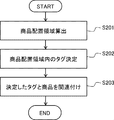
- FIG. 19 shows a specific example when the product management table creation in S103 is automatically performed.
- the product management table creation unit 14 refers to the shelf allocation table 11a and calculates an area (arrangement area) of the display position of the product according to the product size and the shelf allocation information (S201).
- the arrangement area of each product can be calculated by the product size width ⁇ depth, and the face (column) arrangement area can be calculated by multiplying the number of depths of the shelf allocation information.
- the arrangement region may be specified in consideration of the shape of the bottom surface that comes into contact with the product when it is arranged.
- the shape of the bottom surface is stored in the shelf allocation table 11a for each product, and if the shape of the bottom surface is a circle, the area of the circle is calculated to obtain the arrangement region.
- the product management table creation unit 14 refers to the tag position table 11b and determines an RFID tag corresponding to the calculated display area (arrangement area) of the product according to the tag position information (S202). .
- the product management table creation unit 14 compares the product display position area calculated in S201 with the tag position information in the tag position table 11b, and selects an RFID tag included in the product display position area. For example, in the example of FIGS. 15 and 16, the RFID tag whose shelf number, column number, and face match and whose depth position is included in the region of the display position of the product is selected.
- the product management table creation unit 14 creates the product management table 11c by associating the determined RFID tag with the product (S203).
- the product management table creation unit 14 acquires the tag ID of the RFID tag determined in S202 from the tag position table 11b, acquires the product name, manufacturer, and shelf allocation information of the product corresponding to the RFID tag from the shelf allocation table 11a. Each of them is associated and stored in the product management table 11c.
- the position of the RFID tag with the tag ID “12340001” is included in the first area of the depth among the areas where the six items “tuna cans” are arranged.
- the product “tuna can” and the tag ID “12340001” are associated with each other, and among the regions where the six product “tuna cans” are arranged, the second region of the depth includes the RFID tags with tag IDs “12340002” and “12340003”. Since the position is included, the second product “Tuna Can” in the depth is associated with the tag IDs “12340002” and “12340003”.
- the metal foil sheet creating unit 18 creates the metal foil sheet 9 based on the product management table 11c created in S103 (S104).
- the metal foil sheet creation unit 18 generates cutting information indicating the position and shape of the opening 9a based on the position of the RFID tag 5 registered in the product management table 11c, and outputs the cutting information to a cutting machine or the like.
- the cutting machine cuts out the corresponding part of the metal foil sheet 9 according to the cutting information and forms the opening 9a. In addition, you may acquire the metal foil sheet 9 previously formed.
- the metal foil sheet 9 is laid on the RFID tag 5 (tag antenna unit 50) (S105).
- a salesclerk or the like arranges the metal foil sheet 9 created in S111 on the tag antenna unit 50 so that the RFID tag 5 corresponding to the opening 9a is exposed.
- the clerk or the like places merchandise in the arrangement area on the metal foil sheet for merchandise management (product detection) (S106). Subsequently, the following process is repeated to periodically monitor the presence or absence of the product.
- the tag reading unit 15 reads the RFID tag via the reader transmission line 4 (S107).
- the tag reading unit 15 transmits a batch read command for reading all tags to the RFID reader 7, and the RFID reader 7 outputs a signal so as to return the tag ID to all the RFID tags 5.
- the reading operation can be speeded up without performing complicated control such as individually transmitting signals to the RFID tag 5.
- the tag reading unit 15 sequentially designates tag IDs in the product management table 11 c and transmits individual read commands to the RFID reader 7.
- the RFID reader 7 sequentially returns tag IDs to the designated RFID tags 5. A signal may be output.
- the product presence / absence determination unit 16 determines the presence / absence of a product corresponding to the RFID tag 5 based on the signal received from the RFID tag 5 based on the product management table 11c (S106).
- the RFID reader 7 receives a signal returned from the RFID tag 5 designated in batch (or sequentially designated) in S113, measures its signal strength, and outputs the measurement result to the store management apparatus 1.
- the product presence / absence determining unit 16 detects whether the tag with the tag ID described in the product management table 11c has been read, or whether the signal strength of the RFID tag with the corresponding tag ID is greater than or less than a threshold value.
- the RFID tag cannot be read or if the signal strength is less than the threshold value, it is determined that there is a product corresponding to the RFID tag. Otherwise, it is determined that there is no corresponding product. For example, when one product corresponds to a plurality of RFID tags, it may be determined that there is a product when all the signal strengths of the plurality of RFID tags are less than a threshold value, or the signal strength of any of the plurality of RFID tags If the value is less than the threshold, it may be determined that there is a product.
- the determination conditions for a plurality of RFID tags are set to conditions that are suitable for the product to be placed.
- the product management unit 17 executes processing according to the product detection result (S109). For example, the product management unit 17 displays the presence or absence of the product detected in S108 on the display unit, and notifies the store clerk of the product status.
- a metal foil sheet having an opening corresponding to an RFID tag for detecting a product is arranged on the RFID tag. Accordingly, even when a large number of RFID tags are arranged, the operation of unnecessary RFID tags can be stopped and only the necessary RFID tags can be operated, so that the reading operation of the RFID tags can be speeded up. .
- a plurality of RFID tags are fixedly arranged on the reader transmission line in advance.
- a shelf allocation table that associates product information and shelf allocation information
- a tag position table that associates RFID tag tag IDs and RFID tag location information
- the product management table in which the tag ID of the RFID tag is associated is stored. By referring to the product management table, it is determined whether there is a product on the RFID tag. Thereby, even when the display position of the product is changed due to the shelf allocation, the presence or absence of the product can be determined only by changing the shelf allocation table and the product management table. Therefore, since it is not necessary to change the arrangement of the RFID tags, the articles can be managed easily.
- RFID is preliminarily arranged so that a plurality of tags are laid at a position where one tag to be managed is laid at least on the bottom surface of the article or at least the number of articles with a size smaller than the interval between the articles.
- the presence / absence of a product is determined based on the signal strength from the RFID tag on the reader transmission line. For this reason, it is not necessary to attach an RFID tag or a shielding part to the product, and the presence or absence of the product can be managed at a low cost.
- This embodiment is an example of creating an RFID tag table that can be read in a state in which a metal foil sheet is arranged in addition to the first embodiment.
- the store management device 1 stores a reading tag table 11 d in the product information database 11 in addition to the configuration of FIG. 14 of the first embodiment, and further includes a reading tag table creation unit 19. ing.
- FIG. 21 shows an example of the reading tag table 11d.
- the reading tag table 11d is a table showing a list of tag IDs of RFID tags that can be read in a state where the metal foil sheet is arranged.
- the signal intensity received from the RFID tag is stored in association with each tag ID. By using this signal intensity as a threshold value for determining the presence / absence of a product, it is possible to detect the presence / absence of the product with high accuracy.
- the reading tag table creation unit 19 places the metal foil sheet and creates the reading tag table 11d based on the result of reading the RFID tag in a state before the product is placed. For example, the tag reading unit 15 transmits a batch read command for reading all tags to the RFID reader 7, and the RFID reader 7 reads all the RFID tags 5 on the reader transmission line 4.
- the read tag table creation unit 19 receives the tag ID and signal strength of the RFID tag read by the RFID reader 7, and creates the read tag table 11d by associating the received tag ID with the signal strength.
- the reading tag table 11d and the product management table 11c have a common tag ID column, and therefore may be a single table.
- the product management table creation unit 14 may create the product management table 11c by associating the tag IDs read from all the RFID tags 5 with the product, similarly to the read tag table creation unit 19.
- the tag position table 11b is created by associating the tag ID of the RFID tag and the position information of the RFID tag as in the first embodiment (S101), and the product information and the shelf allocation information are associated with each other.
- a table 11a is created (S102), and a product management table 11c is created by associating product information with the tag ID of the RFID tag (S103).
- a metal foil sheet 9 is created based on the product management table 11c (S104), and the metal foil sheet 9 is laid on the RFID tag 5 (S105).
- the tag reading unit 15 reads all RFID tags (S111).
- all the RFID tags are read.
- the tag reading unit 15 transmits a batch read command for reading all the tags to the RFID reader 7, and the RFID reader 7 outputs a signal so as to return the tag ID to all the RFID tags 5.
- the reading tag table creating unit 19 creates the reading tag table 11d based on the reading result of the RFID tag 5 (S112).
- the RFID reader 7 receives the signals returned from all the RFID tags 5 in S111, measures the signal strength, and outputs the measurement results to the store management device 1.
- the reading tag table creation unit 19 creates the reading tag table 11d by associating the tag ID of the received RFID tag with the signal intensity.
- the product management table creation unit 14 may create the product management table 11c based on the reading results from all the RFID tags 5.
- the product presence / absence determination unit 16 detects whether the signal strength of the RFID tag with the tag ID described in the read tag table 11d is greater than or less than the threshold value of the read tag table 11d, and determines whether there is a product corresponding to the RFID tag.
- the presence / absence of a product may be determined based on the tag ID of the product management table 11c.
- a tag reading tag table that can be read in a state where the metal foil sheet is arranged is created, and the presence / absence of a product is determined based on this table. Since the presence / absence of a product is determined based on the reading tag table, the RFID tag corresponding to the opening of the metal foil sheet can be accurately grasped, and the presence / absence of the product can be determined from the reading result of the corresponding RFID tag. As a result, it is only necessary to transmit a signal to only the corresponding RFID tag among all the RFID tags, so that the reading operation can be speeded up. Further, the signal strength received from the RFID tag is stored in the reading tag table, and the presence / absence of the product can be accurately determined by determining the presence / absence of the product using the signal strength as a threshold value.
- the present embodiment is an example in which a shelf sheet is disposed on the metal foil sheet of the first embodiment.
- FIGS. 23 is a perspective view of the tag antenna unit 50, the metal foil sheet 9, and the shelf sheet 10, FIG. 24 is a top view thereof, and FIG. 25 is a front sectional view and a side sectional view thereof.
- the configurations of the tag antenna unit 50 including the reader transmission line 4 and the RFID tag 5 and the metal foil sheet 9 are the same as those in the first embodiment.
- the shelf sheet 10 is placed on the tag antenna unit 50 and the metal foil sheet 9.
- the RFID tag 5 is previously disposed on the reader transmission line 4
- the metal foil sheet 9 is disposed on the RFID tag 5
- the shelf sheet 10 is disposed on the metal foil sheet 9.
- the shelf division sheet (article arrangement sheet) 10 is a sheet for showing shelf allocation (product display position) to a store clerk or the like. When the shelf sheet 10 is arranged, the product is arranged on the shelf sheet 10, so the upper surface of the shelf sheet 10 becomes the product displayable area 2 b.
- the shelf allocation sheet 10 is the size of an area in which products can be placed, and is substantially the same size as the reader transmission line 4 (tag antenna unit 50), the metal foil sheet 9, for example,
- the size includes all the RFID tags 5.
- the size which can cover the area which one kind of goods occupies the shelf including the display position 2a of at least one goods may be sufficient as the shelf allocation sheet 10.
- the shelf allocation sheet 10 may be a material that does not affect the detection of the product (signal strength of the RFID tag), for example, a paper sheet.
- a product arrangement mark 10a is displayed at the position of the product display position 2a.
- the product placement mark 10a has the same size as the product, and a product name is displayed to identify the product to be placed. Since the same product is arranged for each face (column), the product name is displayed on the foremost product arrangement mark 10a.
- the product placement mark 10a may be printed directly on a paper sheet, or may be attached to the paper sheet with a seal or the like.
- the perforated line 10b may be provided on the shelf sheet 10.
- the cut line 10b is formed for each type of product.
- a protective material for protecting the RFID tag 5 may be disposed on the RFID tag 5.
- the shelf sheet 10 may also function as the protective material. Further, there may be a mechanism for aligning the shelf sheet 10 with the RFID tag 5 or the like below. As an alignment mechanism, for example, a mark indicating the arrangement position of the shelf layout sheet 10 may be displayed on the tag antenna unit 50 or the metal foil sheet 9.
- the store management device 1 includes a shelf allocation sheet creation unit 20 in addition to the configuration of FIG. 14 of the first embodiment.
- the shelf layout sheet creation unit (article placement sheet creation unit) 20 creates a product placement mark 10a on the shelf placement sheet 10 at a position corresponding to the product display position 2a.
- the shelf allocation sheet creation unit 20 creates a product placement mark 10a based on a shelf allocation table 11a in which product information and shelf allocation information are linked.
- the shelf allocation sheet creation unit 20 refers to the shelf allocation table 11a and creates the product size graphic (contour) and the product name at the position specified by the shelf allocation information for each product.
- the product placement mark 10a is printed on a sheet of paper using a printer.
- the shelf allocation sheet 10 may be created externally without being created by the store management device 1.
- the shelf allocation table 11a may be created by the shelf allocation software, and the product placement mark 10a may be formed on the shelf allocation sheet 10 based on the shelf allocation table 11a.
- the shelf allocation sheet 10 may be distributed from the retail headquarters to a plurality of retail stores. Further, the merchandise management table 11c may be distributed together with the shelf allocation sheet 10 from the retail headquarters to a plurality of retail stores.
- a tag position table 11b is created by associating the tag ID of the RFID tag with the position information of the RFID tag (S101), and the product information and the shelf allocation information are associated with each other.
- a table 11a is created (S102), and a product management table 11c is created by associating product information with the tag ID of the RFID tag (S103).
- a metal foil sheet 9 is created based on the product management table 11c (S104), and the metal foil sheet 9 is laid on the RFID tag 5 (S105).
- the shelf allocation sheet creating unit 20 creates the shelf allocation sheet 10 based on the shelf allocation table 11a created in S102 (S121).
- the shelf allocation sheet creation unit 20 generates print information indicating the position, size, and characters of the product placement mark 10a based on the shelf allocation information registered in the shelf allocation table 11a, the product size, and the product name. Output to.
- the printer prints the product arrangement mark 10a on the corresponding portion of the shelf layout sheet 10 according to the print information. In addition, you may acquire the shelf allocation sheet
- the shelf sheet 10 is laid on the RFID tag 5 (tag antenna unit 50) (S122).
- the store clerk arranges the shelf allocation sheet 10 created in S121 on the tag antenna unit 50 so that the RFID tag 5 and the product arrangement mark 10a correspond to each other.
- merchandise management product detection
- S104 shelf allocation sheet
- the shelf sheet indicating the display position of the product is arranged on the RFID tag.
- the burden of the product placement work by the store clerk can be reduced, and an arrangement error that erroneously places another product can be prevented.
- the shelf allocation instructions at the headquarters can be thoroughly implemented at all stores.
Abstract
Description
実施の形態の説明に先立って、実施の形態の特徴についてその概要を説明する。図1は、実施の形態に係る物品管理システムの主要な構成を示している。 (Outline of the embodiment)
Prior to the description of the embodiment, an outline of features of the embodiment will be described. FIG. 1 shows a main configuration of an article management system according to an embodiment.
以下、図面を参照して実施の形態1について説明する。図2は、本実施の形態に係る商品管理システムの構成の一例を示している。この商品管理システムは、店舗等において商品陳列棚に陳列されている商品を逐次監視して、商品陳列棚における商品の有無を判断し、また、陳列状態に関連する表示等の処理を行うシステムである。なお、ここでは、商品を管理する商品管理システムの例を説明するが、商品に限らず、本実施の形態で検出可能な、その他の物品を管理する物品管理システムでもよい。 (Embodiment 1)
The first embodiment will be described below with reference to the drawings. FIG. 2 shows an example of the configuration of the merchandise management system according to the present embodiment. This merchandise management system is a system that sequentially monitors the merchandise displayed on merchandise display shelves in stores, etc., determines the presence or absence of merchandise on the merchandise display shelves, and performs processing such as display related to the display status is there. Here, an example of a merchandise management system that manages merchandise will be described. However, the merchandise management system is not limited to merchandise, and may be an article management system that manages other articles that can be detected in the present embodiment.

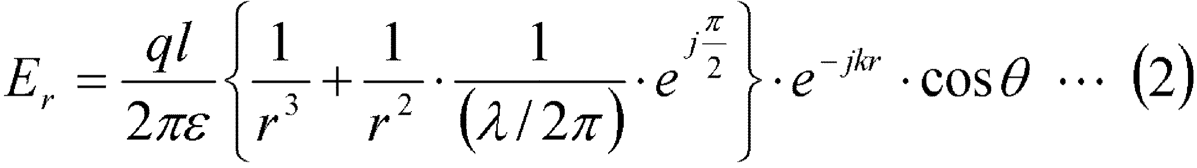
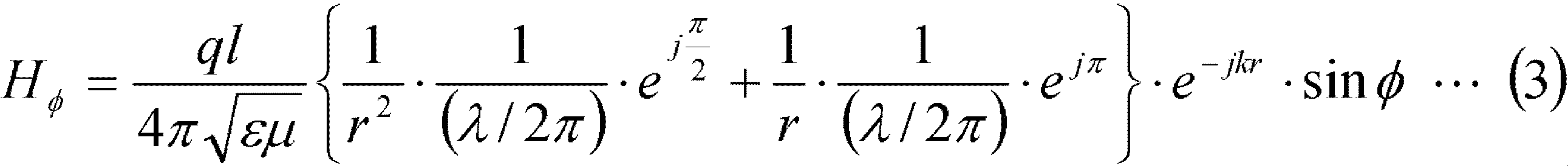

また、さらに、読み取り時間を短縮するため、商品の陳列位置に対応したRFIDタグのみを読み取ってもよい。すなわち、タグ読み取り部15は、商品管理テーブル11c内のタグIDを順次指定して個別リードコマンドをRFIDリーダ7へ送信し、RFIDリーダ7は指定されたRFIDタグ5にタグIDを返すように順次信号を出力してもよい。 First, the
Furthermore, in order to shorten the reading time, only the RFID tag corresponding to the display position of the product may be read. That is, the
以下、図面を参照して実施の形態2について説明する。本実施の形態は、実施の形態1に加えて、金属箔シートを配置した状態で読み取れるRFIDタグのテーブルを作成する例である。 (Embodiment 2)
The second embodiment will be described below with reference to the drawings. This embodiment is an example of creating an RFID tag table that can be read in a state in which a metal foil sheet is arranged in addition to the first embodiment.
また、読み取りタグテーブルにRFIDタグから受信する信号強度を記憶しておき、この信号強度を閾値として商品の有無を判断することで、精度良く商品の有無を判断することができる。 As described above, in the present embodiment, in addition to the first embodiment, a tag reading tag table that can be read in a state where the metal foil sheet is arranged is created, and the presence / absence of a product is determined based on this table. Since the presence / absence of a product is determined based on the reading tag table, the RFID tag corresponding to the opening of the metal foil sheet can be accurately grasped, and the presence / absence of the product can be determined from the reading result of the corresponding RFID tag. As a result, it is only necessary to transmit a signal to only the corresponding RFID tag among all the RFID tags, so that the reading operation can be speeded up.
Further, the signal strength received from the RFID tag is stored in the reading tag table, and the presence / absence of the product can be accurately determined by determining the presence / absence of the product using the signal strength as a threshold value.
以下、図面を参照して実施の形態3について説明する。本実施の形態は、実施の形態1の金属箔シート上に棚割シートを配置する例である。 (Embodiment 3)
The third embodiment will be described below with reference to the drawings. The present embodiment is an example in which a shelf sheet is disposed on the metal foil sheet of the first embodiment.
2 商品
2a 陳列位置
2b 商品陳列可能領域
3 通信ネットワーク
3a 高周波ケーブル
4 リーダ伝送線路
5 RFIDタグ
7 RFIDリーダ
8 商品陳列棚
9 金属箔シート
9a 開口部
10 棚割シート
10a 商品配置マーク
10b 切り取り線
11 商品情報データベース
11a 棚割テーブル
11b タグ位置テーブル
11c 商品管理テーブル
11d 読み取りタグテーブル
12 棚割テーブル作成部
13 タグ位置テーブル作成部
14 商品管理テーブル作成部
15 タグ読み取り部
16 商品有無判断部
17 商品管理部
18 金属箔シート作成部
19 読み取りタグテーブル作成部
20 棚割シート作成部
41 グランドプレーン
42 スペーサ
43 ストリップ導体
44 スペーサ
45 平行二線路
46 分配器
50 タグアンテナユニット
91 カバー層
92 導体層
93 樹脂製シート
94 カバー層
101 リーダ伝送線路
102 RFIDタグ
103 金属シート
103a 開口部
104 タグ読み取り部
105 物品有無判断部
106 物品
107 配置可能領域
108 割当位置
201 RFIDチップ
202 タグアンテナ DESCRIPTION OF
Claims (16)
- 整合終端された伝送線路で構成されたリーダ伝送線路と、
前記リーダ伝送線路上方の物品の配置可能領域に対応して固定され、前記リーダ伝送線路と電磁界結合する複数のRFIDタグと、
前記複数のRFIDタグ上に敷設され、前記複数のRFIDタグのうち、前記配置可能領域に前記物品を配置するために割り当てられた前記物品の割当位置内のRFIDタグに対応する位置に開口部を有する金属シートと、
前記リーダ伝送線路を介して電磁界結合により前記複数のRFIDタグから読み取りを行うタグ読み取り手段と、
前記複数のRFIDタグの読み取り結果に基づいて、前記金属シート上の前記割当位置における前記物品の有無を判断する物品有無判断手段と、
を備える物品管理システム。 A reader transmission line composed of matched-terminated transmission lines;
A plurality of RFID tags that are fixed in correspondence with the dispositionable area of the article above the reader transmission line and are electromagnetically coupled to the reader transmission line;
An opening is laid on the plurality of RFID tags, and an opening is formed at a position corresponding to the RFID tag in the allocation position of the article allocated to arrange the article in the arrangementable area among the plurality of RFID tags. A metal sheet having
Tag reading means for reading from the plurality of RFID tags by electromagnetic field coupling through the reader transmission line;
An article presence / absence judging means for judging the presence / absence of the article at the assigned position on the metal sheet based on the reading results of the plurality of RFID tags;
An article management system comprising: - 前記複数のRFIDタグのサイズは、前記物品が配置されたときに前記配置可能領域と接するサイズよりも小さい、
請求項1に記載の物品管理システム。 The size of the plurality of RFID tags is smaller than the size in contact with the placeable area when the article is placed.
The article management system according to claim 1. - 前記複数のRFIDタグの間隔は、前記物品が配置されたときに前記配置可能領域と接するサイズよりも狭い、
請求項1に記載の物品管理システム。 The interval between the plurality of RFID tags is narrower than the size in contact with the placeable area when the article is placed.
The article management system according to claim 1. - 前記複数のRFIDタグのタグ情報と当該複数のRFIDタグの固定位置とを関連付けたタグ位置テーブルを記憶するタグ位置テーブル記憶手段と、
前記物品の識別情報と、前記配置可能領域に前記物品を配置するために割り当てられた当該物品の割当位置とを関連付けた物品位置テーブルを記憶する物品位置テーブル記憶手段と、
前記タグ位置テーブル及び前記物品位置テーブルに基づき、前記物品の識別情報と前記複数のRFIDタグのタグ情報とを関連付けた物品管理テーブルを記憶する物品管理テーブル記憶手段と、を備え、
前記物品有無判断手段は、前記物品管理テーブルによる前記物品の識別情報と前記複数のRFIDタグのタグ情報との関連付けに基づいて、前記物品の有無を判断する、
請求項1乃至3のいずれか一項に記載の物品管理システム。 Tag position table storage means for storing a tag position table that associates tag information of the plurality of RFID tags and fixed positions of the plurality of RFID tags;
Article position table storage means for storing an article position table in which the identification information of the article is associated with the assigned position of the article assigned to arrange the article in the placeable area;
An article management table storage unit that stores an article management table in which the identification information of the article and tag information of the plurality of RFID tags are associated with each other based on the tag position table and the article position table;
The article presence / absence determining means determines the presence / absence of the article based on an association between identification information of the article and tag information of the plurality of RFID tags by the article management table.
The article management system according to any one of claims 1 to 3. - 前記タグ位置テーブルにおける前記複数のRFIDタグの固定位置と前記物品位置テーブルにおける前記物品の割当位置との関連に応じて、前記物品管理テーブルを作成する物品管理テーブル作成手段を備える、
請求項4に記載の物品管理システム。 Comprising an article management table creating means for creating the article management table according to a relation between a fixed position of the plurality of RFID tags in the tag position table and an assigned position of the article in the article position table;
The article management system according to claim 4. - 前記物品の識別情報と前記複数のRFIDタグのタグ情報とが関連付けて入力され、当該入力された関連付けに応じて前記物品管理テーブルを作成する物品管理テーブル作成手段を備える、
請求項4に記載の物品管理システム。 The article identification information and the tag information of the plurality of RFID tags are inputted in association with each other, and the article management table creating means for creating the article management table according to the inputted association is provided.
The article management system according to claim 4. - 前記物品管理テーブルを参照し、前記物品管理テーブル内のRFIDタグの位置に応じて前記開口部を形成する金属シート作成手段を備える、
請求項4乃至6のいずれか一項に記載の物品管理システム。 A metal sheet creating means for referring to the article management table and forming the opening according to the position of the RFID tag in the article management table;
The article management system according to any one of claims 4 to 6. - 前記金属シート上に敷設され、前記物品の割当位置が表示された物品配置シートを備え、
前記物品有無判断手段は、前記物品配置シート上に配置された前記物品の有無を判断する、
請求項1乃至7のいずれか一項に記載の物品管理システム。 An article placement sheet laid on the metal sheet and displaying the assigned position of the article;
The article presence / absence determining means determines the presence / absence of the article arranged on the article arrangement sheet.
The article management system according to any one of claims 1 to 7. - 前記金属シート上に敷設され、前記物品の割当位置が表示された物品配置シートを備え、
前記物品有無判断手段は、前記物品配置シート上に配置された前記物品の有無を判断し、
前記物品位置テーブルを参照し、前記物品位置テーブル内の物品の割当位置に応じて前記物品配置シートを作成する物品配置シート作成手段を備える、
請求項4乃至7のいずれか一項に記載の物品管理システム。 An article placement sheet laid on the metal sheet and displaying the assigned position of the article;
The article presence / absence judging means judges the presence / absence of the article placed on the article placement sheet,
An article arrangement sheet creating means for referring to the article position table and creating the article arrangement sheet according to the assigned position of the article in the article position table;
The article management system according to any one of claims 4 to 7. - 前記タグ読み取り手段は、前記複数のRFIDタグの全てを一括で読み取り、
前記物品有無判断手段は、前記読み取り結果の全てに基づいて、前記物品の有無を判断する、
請求項1乃至9のいずれか一項に記載の物品管理システム。 The tag reading means reads all of the plurality of RFID tags at a time,
The article presence / absence determining means determines the presence / absence of the article based on all the reading results.
The article management system according to any one of claims 1 to 9. - 前記タグ読み取り手段は、前記複数のRFIDタグの全てを一括で読み取り、
前記物品有無判断手段は、前記読み取り結果のうち前記物品管理テーブル内のRFIDタグの読み取り結果に基づいて、前記物品の有無を判断する、
請求項4乃至7のいずれか一項に記載の物品管理システム。 The tag reading means reads all of the plurality of RFID tags at a time,
The article presence / absence determining means determines the presence / absence of the article based on the reading result of the RFID tag in the article management table among the reading results.
The article management system according to any one of claims 4 to 7. - 前記タグ読み取り手段は、前記複数のRFIDタグのうち前記物品管理テーブル内のRFIDタグを個別に読み取り、
前記物品有無判断手段は、前記読み取り結果の全てに基づいて、前記物品の有無を判断する、
請求項4乃至7のいずれか一項に記載の物品管理システム。 The tag reading means individually reads RFID tags in the article management table among the plurality of RFID tags,
The article presence / absence determining means determines the presence / absence of the article based on all the reading results.
The article management system according to any one of claims 4 to 7. - 前記金属シートを敷設し前記物品を配置する前に、前記複数のRFIDタグから読み取ったタグ情報を記憶する読み取りタグテーブルを作成する読み取りタグテーブル作成手段を備え、
前記物品有無判断手段は、前記読み取りタグテーブルに含まれる前記タグ情報に対応する前記物品の有無を判断する、
請求項1乃至12のいずれか一項に記載の物品管理システム。 Read tag table creating means for creating a read tag table for storing tag information read from the plurality of RFID tags before laying the metal sheet and placing the article,
The article presence / absence determining means determines the presence / absence of the article corresponding to the tag information included in the read tag table.
The article management system according to any one of claims 1 to 12. - 前記読み取りタグテーブルは、前記複数のRFIDタグから読み取ったタグ情報と、前記複数のRFIDタグから受信した信号強度とを関連付け、
前記物品有無判断手段は、前記複数のRFIDタグから受信した信号強度と前記読み取りタグテーブルに含まれる信号強度を比較し、前記物品の有無を判断する、
請求項13に記載の物品管理システム。 The read tag table associates tag information read from the plurality of RFID tags with signal strength received from the plurality of RFID tags,
The article presence / absence determining means compares the signal intensity received from the plurality of RFID tags with the signal intensity included in the reading tag table, and determines the presence / absence of the article.
The article management system according to claim 13. - 整合終端された伝送線路で構成されたリーダ伝送線路上方の物品の配置可能領域に、前記リーダ伝送線路と電磁界結合する複数のRFIDタグを固定し、
前記複数のRFIDタグのうち、前記配置可能領域に前記物品を配置するために割り当てられた前記物品の割当位置内のRFIDタグに対応する位置に開口部を有する金属シートを、前記複数のRFIDタグ上に敷設し、
前記リーダ伝送線路を介して電磁界結合により前記複数のRFIDタグから読み取りを行い、
前記複数のRFIDタグの読み取り結果に基づいて、前記金属シート上の前記割当位置における前記物品の有無を判断する、
物品管理方法。 A plurality of RFID tags that are electromagnetically coupled to the reader transmission line are fixed to a region where the article can be arranged above the reader transmission line, which is configured by a transmission line that is matched and terminated.
Among the plurality of RFID tags, a metal sheet having an opening at a position corresponding to the RFID tag in the allocation position of the article allocated for arranging the article in the arrangementable region, the plurality of RFID tags Laying on top,
Read from the plurality of RFID tags by electromagnetic coupling through the reader transmission line,
Based on the reading results of the plurality of RFID tags, the presence or absence of the article at the assigned position on the metal sheet is determined.
Article management method. - コンピュータに物品管理処理を実行させるための物品管理プログラムであって、
前記物品管理処理は、
整合終端された伝送線路で構成されたリーダ伝送線路上方の物品の配置可能領域に、前記リーダ伝送線路と電磁界結合する複数のRFIDタグを固定し、前記複数のRFIDタグのうち、前記配置可能領域に前記物品を配置するために割り当てられた前記物品の割当位置内のRFIDタグに対応する位置に開口部を有する金属シートを、前記複数のRFIDタグ上に敷設した後に、前記リーダ伝送線路を介して電磁界結合により前記複数のRFIDタグから読み取りを行い、
前記複数のRFIDタグの読み取り結果に基づいて、前記金属シート上の前記割当位置における前記物品の有無を判断する、
物品管理プログラムが格納された非一時的なコンピュータ可読媒体。 An article management program for causing a computer to execute an article management process,
The article management process includes:
A plurality of RFID tags that are electromagnetically coupled to the reader transmission line are fixed to an arrangement area of an article above the reader transmission line that is configured with a transmission line that is matched and terminated. Among the plurality of RFID tags, the arrangement is possible. After laying a metal sheet having an opening at a position corresponding to an RFID tag in an allocation position of the article allocated to arrange the article in a region on the plurality of RFID tags, the reader transmission line is Reading from the plurality of RFID tags by electromagnetic field coupling,
Based on the reading results of the plurality of RFID tags, the presence or absence of the article at the assigned position on the metal sheet is determined.
A non-transitory computer-readable medium storing an article management program.
Priority Applications (3)
| Application Number | Priority Date | Filing Date | Title |
|---|---|---|---|
| JP2015518050A JP6197870B2 (en) | 2013-05-20 | 2014-02-25 | Article management system, article management method, and article management program |
| EP14800808.9A EP3000751A4 (en) | 2013-05-20 | 2014-02-25 | Product management system, product management method, and non-temporary computer-readable medium for storing product-management program |
| US14/892,233 US9652647B2 (en) | 2013-05-20 | 2014-02-25 | Article management system, article management method, and non-transitory computer readable medium storing article management program |
Applications Claiming Priority (2)
| Application Number | Priority Date | Filing Date | Title |
|---|---|---|---|
| JP2013105983 | 2013-05-20 | ||
| JP2013-105983 | 2013-05-20 |
Publications (1)
| Publication Number | Publication Date |
|---|---|
| WO2014188637A1 true WO2014188637A1 (en) | 2014-11-27 |
Family
ID=51933212
Family Applications (1)
| Application Number | Title | Priority Date | Filing Date |
|---|---|---|---|
| PCT/JP2014/000975 WO2014188637A1 (en) | 2013-05-20 | 2014-02-25 | Product management system, product management method, and non-temporary computer-readable medium for storing product-management program |
Country Status (4)
| Country | Link |
|---|---|
| US (1) | US9652647B2 (en) |
| EP (1) | EP3000751A4 (en) |
| JP (1) | JP6197870B2 (en) |
| WO (1) | WO2014188637A1 (en) |
Cited By (1)
| Publication number | Priority date | Publication date | Assignee | Title |
|---|---|---|---|---|
| US10360533B2 (en) | 2016-05-27 | 2019-07-23 | Walmart Apollo, Llc | Product display surface apparatus and method |
Families Citing this family (9)
| Publication number | Priority date | Publication date | Assignee | Title |
|---|---|---|---|---|
| WO2016052717A1 (en) * | 2014-10-02 | 2016-04-07 | シャープ株式会社 | Control device, display device, communication terminal, medium, display control system, method for controlling control device, and control program |
| CN104836619B (en) | 2015-03-30 | 2017-08-29 | 青岛海信宽带多媒体技术有限公司 | A kind of optical device |
| US20180235383A1 (en) * | 2015-08-10 | 2018-08-23 | Ground Star Llc | Modular rfid shelving |
| WO2018116700A1 (en) * | 2016-12-22 | 2018-06-28 | 株式会社村田製作所 | Article management system |
| FR3072492B1 (en) | 2017-10-13 | 2019-11-08 | Ses-Imagotag | METHOD FOR INITIALIZING OR UPDATING A REALOGRAM DATABASE FOR A LINEAR, UTILIZING OPTICAL SIGNALS ISSUED BY GONDOLA ELECTRONIC LABELS |
| CN109953567A (en) * | 2017-12-26 | 2019-07-02 | 南京德美密胺制品有限公司 | A kind of snack bar intelligence pick-up platform |
| DE102018129886A1 (en) * | 2018-11-27 | 2020-05-28 | Chep Technology Pty Ltd. | Goods storage system |
| US20220380120A1 (en) * | 2021-05-26 | 2022-12-01 | Rebound International, LLC | Wall Panel for an Automated Inventory Module |
| CN113538745B (en) * | 2021-07-15 | 2023-03-21 | 山东三维海容科技有限公司 | Transmission box and transmission management method |
Citations (5)
| Publication number | Priority date | Publication date | Assignee | Title |
|---|---|---|---|---|
| US7271724B2 (en) | 2005-03-28 | 2007-09-18 | Accenture Global Services Gmbh | Interfering smart shelf |
| JP2010263336A (en) * | 2009-04-30 | 2010-11-18 | Nitta Ind Corp | Wireless communication improving sheet, ic tag for wireless communication including the same, and cylinder management method |
| JP2012038035A (en) * | 2010-08-05 | 2012-02-23 | Toshiba Tec Corp | Shop guide system, server device, information processing terminal, and control program |
| JP2012055146A (en) * | 2010-09-03 | 2012-03-15 | Hitachi Ltd | Wireless power feeding system, position detection apparatus |
| JP5128898B2 (en) | 2007-10-23 | 2013-01-23 | 株式会社岡村製作所 | Product display device |
Family Cites Families (2)
| Publication number | Priority date | Publication date | Assignee | Title |
|---|---|---|---|---|
| US8120488B2 (en) * | 2009-02-27 | 2012-02-21 | Rf Controls, Llc | Radio frequency environment object monitoring system and methods of use |
| US8695878B2 (en) * | 2011-08-31 | 2014-04-15 | Djb Group Llc | Shelf-monitoring system |
-
2014
- 2014-02-25 WO PCT/JP2014/000975 patent/WO2014188637A1/en active Application Filing
- 2014-02-25 EP EP14800808.9A patent/EP3000751A4/en not_active Withdrawn
- 2014-02-25 US US14/892,233 patent/US9652647B2/en active Active
- 2014-02-25 JP JP2015518050A patent/JP6197870B2/en active Active
Patent Citations (5)
| Publication number | Priority date | Publication date | Assignee | Title |
|---|---|---|---|---|
| US7271724B2 (en) | 2005-03-28 | 2007-09-18 | Accenture Global Services Gmbh | Interfering smart shelf |
| JP5128898B2 (en) | 2007-10-23 | 2013-01-23 | 株式会社岡村製作所 | Product display device |
| JP2010263336A (en) * | 2009-04-30 | 2010-11-18 | Nitta Ind Corp | Wireless communication improving sheet, ic tag for wireless communication including the same, and cylinder management method |
| JP2012038035A (en) * | 2010-08-05 | 2012-02-23 | Toshiba Tec Corp | Shop guide system, server device, information processing terminal, and control program |
| JP2012055146A (en) * | 2010-09-03 | 2012-03-15 | Hitachi Ltd | Wireless power feeding system, position detection apparatus |
Non-Patent Citations (1)
| Title |
|---|
| See also references of EP3000751A4 |
Cited By (1)
| Publication number | Priority date | Publication date | Assignee | Title |
|---|---|---|---|---|
| US10360533B2 (en) | 2016-05-27 | 2019-07-23 | Walmart Apollo, Llc | Product display surface apparatus and method |
Also Published As
| Publication number | Publication date |
|---|---|
| JPWO2014188637A1 (en) | 2017-02-23 |
| EP3000751A1 (en) | 2016-03-30 |
| JP6197870B2 (en) | 2017-09-20 |
| EP3000751A4 (en) | 2017-06-28 |
| US9652647B2 (en) | 2017-05-16 |
| US20160086005A1 (en) | 2016-03-24 |
Similar Documents
| Publication | Publication Date | Title |
|---|---|---|
| JP6256465B2 (en) | Article management system, article management method, and article management program | |
| JP6197870B2 (en) | Article management system, article management method, and article management program | |
| JP5904287B2 (en) | Product management system | |
| US7310070B1 (en) | Radio frequency identification shelf antenna with a distributed pattern for localized tag detection | |
| JP6070798B2 (en) | RFID system, article management system, and human body detection system | |
| WO2015133051A1 (en) | Article management system | |
| JP5761477B1 (en) | Article management system and article management method | |
| JP2011060230A (en) | Article management system | |
| JP6406243B2 (en) | Article management system, article management method, and article management program | |
| JP6319091B2 (en) | Marketing data collection system | |
| US9947195B2 (en) | Article management system | |
| JP2011154655A (en) | Article information reading system and article information reading method | |
| JP2011087288A (en) | Antenna unit for shelf | |
| JP6201659B2 (en) | Article management system and sensor sheet thereof | |
| JP2015129848A (en) | Product promotion system and product promotion program | |
| JP2015121863A (en) | Article management system, reader antenna and sensor sheet |
Legal Events
| Date | Code | Title | Description |
|---|---|---|---|
| 121 | Ep: the epo has been informed by wipo that ep was designated in this application |
Ref document number: 14800808 Country of ref document: EP Kind code of ref document: A1 |
|
| ENP | Entry into the national phase |
Ref document number: 2015518050 Country of ref document: JP Kind code of ref document: A |
|
| WWE | Wipo information: entry into national phase |
Ref document number: 14892233 Country of ref document: US |
|
| NENP | Non-entry into the national phase |
Ref country code: DE |
|
| REEP | Request for entry into the european phase |
Ref document number: 2014800808 Country of ref document: EP |
|
| WWE | Wipo information: entry into national phase |
Ref document number: 2014800808 Country of ref document: EP |