WO2014174992A1 - スピーカアレイシステム - Google Patents
スピーカアレイシステム Download PDFInfo
- Publication number
- WO2014174992A1 WO2014174992A1 PCT/JP2014/059248 JP2014059248W WO2014174992A1 WO 2014174992 A1 WO2014174992 A1 WO 2014174992A1 JP 2014059248 W JP2014059248 W JP 2014059248W WO 2014174992 A1 WO2014174992 A1 WO 2014174992A1
- Authority
- WO
- WIPO (PCT)
- Prior art keywords
- unit
- speaker
- casing
- housing
- array system
- Prior art date
- Legal status (The legal status is an assumption and is not a legal conclusion. Google has not performed a legal analysis and makes no representation as to the accuracy of the status listed.)
- Ceased
Links
Images










Classifications
-
- H—ELECTRICITY
- H04—ELECTRIC COMMUNICATION TECHNIQUE
- H04R—LOUDSPEAKERS, MICROPHONES, GRAMOPHONE PICK-UPS OR LIKE ACOUSTIC ELECTROMECHANICAL TRANSDUCERS; ELECTRIC HEARING AIDS; PUBLIC ADDRESS SYSTEMS
- H04R1/00—Details of transducers, loudspeakers or microphones
- H04R1/20—Arrangements for obtaining desired frequency or directional characteristics
- H04R1/32—Arrangements for obtaining desired frequency or directional characteristics for obtaining desired directional characteristic only
- H04R1/40—Arrangements for obtaining desired frequency or directional characteristics for obtaining desired directional characteristic only by combining a number of identical transducers
- H04R1/403—Arrangements for obtaining desired frequency or directional characteristics for obtaining desired directional characteristic only by combining a number of identical transducers loud-speakers
-
- H—ELECTRICITY
- H04—ELECTRIC COMMUNICATION TECHNIQUE
- H04R—LOUDSPEAKERS, MICROPHONES, GRAMOPHONE PICK-UPS OR LIKE ACOUSTIC ELECTROMECHANICAL TRANSDUCERS; ELECTRIC HEARING AIDS; PUBLIC ADDRESS SYSTEMS
- H04R1/00—Details of transducers, loudspeakers or microphones
- H04R1/02—Casings; Cabinets ; Supports therefor; Mountings therein
- H04R1/025—Arrangements for fixing loudspeaker transducers, e.g. in a box, furniture
Definitions
- the present invention relates to a speaker array system in which a plurality of speaker bodies are arranged.
- a stereo system is known as the simplest system for reproducing this acoustic space.
- the sound space is reproduced by making a difference (panning) in the sound pressure and time of the sound output from the speakers installed on the left and right of the viewer.
- a substantially accurate acoustic space is reproduced only on the center line that intersects the midpoint of the left and right speakers that are installed.
- the sound arrival time difference and the sound pressure difference change, and the sound space as intended by the sound content creator is not reproduced.
- Other multi-channel playback methods such as 5.1ch, 7.1ch, 9.1ch, and 22.2ch have also been proposed.
- the sound image and sound quality are improved. to degrade.
- Non-Patent Document 1 proposes a Wave Field Synthesis (WFS) technique using a wavefront synthesis reproduction method.
- WFS Wave Field Synthesis
- an array speaker also referred to as a speaker array
- a plurality of speakers are arranged in an array (linear or curved) is used to virtually set the sound from each speaker.
- the wavefront generated from the virtual sound image position is reproduced, and the sound image position is perceived by the virtual sound image position.
- each virtual sound source includes the sound of each instrument and the position information where the instrument is arranged.
- the sound signal of each virtual sound source does not necessarily need to be for each musical instrument, but the direction and magnitude of each sound intended by the content creator need to be expressed using the concept of a virtual sound source.
- This wavefront synthesis reproduction method reproduces a wavefront that is substantially the same as the wavefront generated in real space. Therefore, unlike the stereo system, it is possible to view the sound in the intended acoustic space other than a predetermined position. In other words, the sweet spot in the wavefront synthesis reproduction method is a wide area.
- Patent Document 1 discloses a housing for such an array speaker.
- the housing described in Patent Document 1 is a substantially rectangular parallelepiped speaker housing for mounting an array speaker, and has partition plates that partition the opening and the internal space of the speaker housing at both ends. Since this casing has openings at both ends, the length of the resonance tube formed in accordance with the position of the partition plate changes, so that the sound pressure level at a predetermined resonance frequency can be emphasized. Yes.
- the casing described in Patent Document 2 includes a speaker attachment for attaching a speaker and a casing main body for arranging and attaching a predetermined number of speaker attachments.
- the speaker fixtures are arranged in a state of being engaged with each other by protrusions and grooves, and are screwed to the casing main body with screws for attaching the speakers and the speaker fixture.
- a speaker array system capable of reproducing sound content by the wavefront synthesis reproduction method can be provided by attaching a number of speaker bodies suitable for the case to the array speaker enclosure described in Patent Document 1.
- the width and length required for the array speaker housing in other words, the number of speaker bodies required is not necessarily constant.
- the width of the display surface is about 88.6 cm.
- the horizontal width of the display surface is about 115.1 cm.
- Such a problem can be solved by preparing multiple types of speaker array systems so as to have a width according to the equipment to be installed, but the number of lineups increases, and the mold for generating the array speaker enclosure The number will increase, leading to a significant increase in cost.
- the speaker array system described in Patent Document 1 cannot easily change the width and length of the array speaker.
- the openings and partition plates described in Patent Document 1 are not essential.
- the speaker mounting tool described in Patent Document 2 is attached to the housing body side by screws for attaching the speaker body, and the number of speaker bodies can be arbitrarily changed by changing the design of the housing body on the equipment side to be attached. Can be changed.
- the speaker fixture described in Patent Document 2 the array speaker cannot be attached to the casing body on the device side after a plurality of speaker fixtures are connected to form the array speaker. It is necessary to attach the fixture, which takes time and labor, and the structure of the speaker fixture is complicated.
- the present invention has been made in view of the above-described actual situation, and the object thereof is to simply and use a small number of parts when arranging a plurality of speaker bodies, and to easily change the number of speaker bodies arranged. It is an object of the present invention to provide a speaker array system that can do this.
- a first technical means of the present invention is a speaker array system including a plurality of unit housings each having a speaker body for outputting an acoustic signal fixed by a fixture.
- the unit housings are connected to each other by the fixture.
- a speaker array system including a plurality of unit housings in which a speaker body for outputting an acoustic signal is fixed by a fixture, and when connecting the plurality of unit housings. And an adjustment unit housing for adjusting a distance between the unit housings, and the unit housings and / or the unit housing and the adjustment unit housing are connected to each other by the fixing tool. It is characterized by that.
- the adjustment unit housing has a partition plate for partitioning a space in the adjustment unit housing.
- a gasket for improving airtightness is provided at a connection portion between the unit casings. It is.
- a gasket for enhancing airtightness is provided at a connection portion between the unit housing and the adjustment unit housing. It is what.
- the speaker array system of the present invention when arranging a plurality of speaker bodies, a simple and small number of components are required, and the number of speaker bodies arranged can be easily changed.
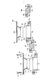
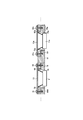
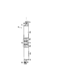
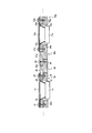
- FIG. 1 shows the example of 1 structure of the speaker array system which concerns on the 2nd Embodiment of this invention, and is sectional drawing which shows the state after assembling from the state of FIG. It is sectional drawing which shows the other structural example of the speaker array system which concerns on the 2nd Embodiment of this invention. It is sectional drawing which shows one structural example of the speaker array system which concerns on the 3rd Embodiment of this invention. It is sectional drawing which shows the other structural example of the speaker array system which concerns on the 3rd Embodiment of this invention. It is a front view which shows one structural example of the unit which consists of a housing
- FIG. 13B is a top view of the unit of FIG. 13A. It is a left view of the unit of FIG. 13A.
- FIG. 13B is a right side view of the unit of FIG. 13A.
- FIG. 14B is a top view of the unit housing for adjustment in FIG. 14A.
- FIG. 14B is a left side view of the adjustment unit housing of FIG. 14A.
- FIG. 15B is a top view of the unit housing for adjustment in FIG. 15A.
- FIG. 15B is a left side view of the adjustment unit housing of FIG. 15A.
- FIG. 15B is a right side view of the adjustment unit housing of FIG. 15A. It is a front view which shows the other structural example of the speaker array system which concerns on the 4th Embodiment of this invention.
- the speaker array system includes a speaker main body for outputting an acoustic signal and a plurality of unit housings for fixing one or a plurality of the speaker main bodies.
- Each speaker body is connected to an audio signal reproduction device by wiring, and the reproduced audio signal can be output as a sound from each speaker body.
- Such an audio signal reproduction device and a speaker array system can be mounted on various AV devices such as a television device.
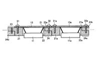
- FIG. 1 and 2 are diagrams showing a configuration example of a speaker array system according to the present embodiment.
- FIG. 1 is a cross-sectional view showing a state before assembly (state of a speaker body mounting surface)
- FIG. 2 is a diagram of FIG. It is sectional drawing which shows the state after assembling from a state.
- the speaker array system includes, for example, as shown in FIG. 1, a speaker body 10, a unit housing 20, and fixtures 31 and 32 such as screws.
- the speaker body 10 is a cone-type speaker, and is mainly composed of a cone-type diaphragm 12 and a magnet 11 serving as a driving mechanism for the cone-type diaphragm 12 and a wiring (not shown).
- the speaker body basically refers to a portion of the speaker device excluding the housing, or a portion that emits sound (mainly a diaphragm and its driving mechanism), and can also be called a speaker unit.
- the flat part 13 of the cone-shaped diaphragm 12 is provided with holes 14 and 15 for inserting the fixtures 31 and 32.
- the holes illustrated by the holes 14 and 15 are provided at four locations (four corners) of the flat portion 13 of the diaphragm 12, and the number of fixtures 31 and 32 is four per one speaker main body 10.
- holes 14 and 15 holes for fixing with the fixtures 31, 32, etc. have shapes suitable for the fixtures.
- the fixture 31 is a screw
- the hole 14 or the like is also formed in a shape that matches the screw, or has a hardness that allows the screw to be screwed in.
- a normal cone type speaker is described as the speaker body 10, the present invention is not limited to this.
- it may be a speaker using a double cone type diaphragm with a small diameter cone type diaphragm attached to the center of the cone type diaphragm, a horn type speaker, a dome type speaker, and the diaphragm is a ribbon type.
- the speaker may be such that a frame provided around it is screwed.
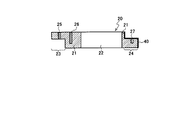
- the unit housing 20 is a housing for fixing the speaker main body 10, and a hole 22 for accommodating a portion of the diaphragm 12 of the speaker main body 10 is provided in a central portion of the main body 21.
- This unit case 20 can be called a unit case for a speaker unit.
- the unit housings (for example, the unit housing 20 and the unit housing 20a) are fixed to each other by a fixing device (for example, the fixing device 32) for fixing the speaker body to the unit housing.
- a fixing device for example, the fixing device 32
- the speaker array system of the present embodiment includes a plurality of unit housings in which speaker bodies for outputting acoustic signals are fixed by fixtures, and these unit housings are connected to each other by the fixtures. Yes.
- the upper part protrudes so as to be connected to an adjacent unit casing (in this example, the unit casing 20 a).
- an adjacent unit casing in this example, the unit casing 20 a.
- the unit housing 20 is provided with a unit fixing hole 26 for fixing the speaker body 10 and unit housing fixing holes at the male end 23 and the female end 24 for fixing the adjacent unit housing 20a. 25 and 27 are provided.
- the unit fixing hole 26 is called with such a name because the speaker body 10 can be called a speaker unit.
- the speaker main body 10a has the same configuration as the speaker main body 10, and includes a magnet 11a, a cone-shaped diaphragm 12a having a flat portion 13a in which holes 14a and 15a are bored, wiring not shown, and the like.
- the unit casing 20a has the same configuration as the unit casing 20, and has a male end 23a having a hole 22a in the central portion of the main body 21a and a unit casing fixing hole 25a at both ends, and a unit casing.
- a female end 24a having a fixing hole 27a is provided, and a unit fixing hole 26a is provided between the hole 22a of the main body 21a and the unit housing fixing hole 25a.
- the unit casing 20b has the same configuration, and here, the end of the reference numeral in each configuration of the unit casing 20a is represented by a symbol changed from “a” to “b”.
- the female end 24 of the unit housing 20 and the male end 23a of the unit housing 20a are overlapped as shown in FIG. It fixes with the fixing tool 32 with the speaker main body 10 from the top.
- the fixture 32 is fixed to the unit casing fixing hole 27 of the unit casing 20 through the hole 15 of the speaker body 10 and the unit casing fixing hole 25a of the unit casing 20a.
- the fixing tool 31 is fixed to the unit fixing hole 26 of the unit housing 20 through the hole 14 of the speaker body 10.
- the adjacent unit casings 20 and 20a can be fixed to each other with fixing tools 31 and 32 for fixing the speaker main body 10 to the unit casing 20, as shown in FIG. Then, a necessary number of such sets can be connected to form an arbitrary number of speaker array housings, and an arbitrary width (and length) speaker array system can be configured.
- the holes 14 and 15 are not limited to four locations per diaphragm 12, but may be two locations. It shall be fixed with the fixing tools 31 and 32 for the speaker main bodies 10. FIG.
- the shape of the unit casings 20, 20a, and 20b to which the speaker body 10 is attached is expressed as a planar baffle.
- a sealed type a bass reflex type, a back load horn, etc. Any shape such as a mold may be used, and the shape is not limited to a flat surface. Of these, the sealed type will be described later in the fourth embodiment.
- FIG. 3 is a cross-sectional view showing another configuration example of the speaker array system according to the present embodiment.
- a gasket 40 may be separately attached to a connection portion (joint portion) between unit housings. Thereby, the airtightness as the whole array speaker housing (speaker array system) can be enhanced.
- Such a gasket 40 can be applied to other configuration examples described later. Moreover, as the gasket 40, the assembly process may be reduced by applying a material usable as a gasket to one or both of the male end 23 and the female end 24.
- FIGS. 4 and 5 are diagrams showing another configuration example of the speaker array system according to the present embodiment.
- FIG. 4 is a cross-sectional view showing a state before assembly
- FIG. 5 is a diagram after assembly from the state of FIG. It is sectional drawing which shows this state.
- a lid unit housing 60a and a lid unit housing 60z having the same configuration may be configured to close both ends.
- the lid unit housing 60a is provided with a stepped portion 63a at the upper end 62a of the main body 61a so as to match the shapes of the main body 21a and the male end 23a of the unit housing 20a, and the stepped portion 63a has a unit housing.
- a unit housing fixing hole 64a for fixing the body 20a by the fixing tool 33a is provided.
- a penetrating unit fixing hole 56a is provided in the main body 21a.
- the fixture 33a and the fixtures 34a, 33z, and 34z have the same configuration as the fixtures 31 and 32, and the fixtures 33a and 34z are formed longer.
- the unit housing fixing hole 64a may be provided so as to penetrate the lid unit housing 60a.
- the lid unit casing 60z has the same configuration as the lid unit casing 60a.
- the end of the reference numeral in each configuration of the lid unit casing 60a is “a”.
- the symbol is changed from “z” to “z”.
- the speaker main body 10z has the same configuration as the speaker main body 10a, and here, the end of the reference numeral in each configuration of the speaker main body 10a is represented by a symbol changed from “a” to “z”.
- the unit casing 20z has the same configuration as that of the unit casing 20a.
- the end of the reference numeral in each configuration of the unit casing 20a is represented by a symbol that is changed from “a” to “z”.
- the male end 23a of the unit casing 20a and the lid unit casing 60a are connected.
- the upper end portion 62a is overlapped, the main body 21a and the stepped portion 63a are overlapped, and the speaker main body 10a and the fixture 33a are fixed from above.
- the fixing tool 33a is fixed to the unit housing fixing hole 64a of the lid unit housing 60a through the hole 14a of the speaker body 10a and the unit fixing hole 56a of the unit housing 20a.
- the other end side of the speaker main body 10a is provided with a fixture 34a through the hole 15a of the speaker main body 10a and the unit case fixing hole of the adjacent unit case. It fixes to the unit housing
- the stepped portion 63z of the female end 24z of the unit casing 20z and the lid unit casing 60z. are fixed together with the speaker main body 10z by the fixing tool 34z.
- the fixture 34z is fixed to the unit casing fixing hole 64z of the lid unit casing 60z through the hole 15z of the speaker body 10z and the unit casing fixing hole 57z of the unit casing 20z.
- a gap is generated between the flat portion 13z and the female end 24z at a portion other than the fixture 34z.
- the lid unit housing 60z may be configured to fill the gap.
- the unit housings 20 a,..., 20 z are fixed adjacent to each other with fixing tools 33 a, 34 a for fixing the speaker body 10 to the unit housing 20.
- both ends can be fixed by the lid unit casings 60a and 60z.
- FIGS. 6 and 7 are diagrams showing another configuration example of the speaker array system according to the present embodiment.
- FIG. 6 is a cross-sectional view showing a state before assembly
- FIG. 7 is after assembly from the state of FIG. It is sectional drawing which shows this state.
- the unit case 20 of the configuration example illustrated in FIG. 6 is provided with two unit case fixing holes 25 and 26 instead of the unit case fixing hole 25 and the unit fixing hole 26 of FIG.
- the unit housing fixing hole 26 in FIG. 6 is a through hole.
- the unit casing 20 of FIG. 6 is provided with another unit casing fixing hole 28 in addition to the unit casing fixing hole 27 of FIG.
- the female end 24 of the unit casing 20 and the male end 23a of the unit casing 20a are overlapped, It fixes with the fixing tools 32 and 31a from the upper side with the right end side of the speaker main body 10 and the left end side of the speaker main body 10a.
- the fixture 32 is fixed to the unit casing fixing hole 27 via the hole 15 and the unit casing fixing hole 25a
- the fixing tool 31a is fixed to the unit casing via the hole 14a and the unit casing fixing hole 26a.
- the fixing tool 31 is fixed to the unit fixing hole 26 through the hole 14.
- the adjacent unit casings 20 and 20a can be fixed with fixing tools 32 and 31a for fixing the speaker main bodies 10 and 10a to the unit housings 20 and 20a.
- reference numeral 23c denotes a male end of the left end unit casing
- 31c denotes a fixing tool for fixing the left end speaker body
- 24d denotes a female end of the right end unit casing.
- the joint (female end, male end) of the unit housing is a seat type, but other shapes such as irregularities, joints, joints, etc. are adopted.
- the present invention is not limited to a simple seat type. However, it is preferable that there is basically no gap when both shapes are matched and combined.
- the housing to which the speaker main body is attached is made into a unit housing (the fixed housing for the speaker main body is unitized) so that an arbitrary number can be joined and the unit housings can be joined together. Is unified with the fixture of the speaker body, so that the width (or length) of the speaker array when it is arrayed can be arbitrarily and easily changed. Moreover, by efficiently joining, the number of parts can be reduced, and the configuration of any part does not have to be complicated. Furthermore, since the speaker array system is constructed by connecting the unit housings to which the speaker main body is fixed, the system can be mounted on the AV equipment, so that the work efficiency is improved.
- FIG. 8 and 9 are diagrams showing a configuration example of the speaker array system according to the present embodiment.
- FIG. 8 is a cross-sectional view showing a state of the speaker body mounting surface before assembly
- FIG. 9 is an assembly from the state of FIG. It is sectional drawing which shows the state after performing.
- the distance between the speaker bodies is constant.
- the distance between the speaker bodies can be changed (in other words, the width of the speaker array can be changed with the same number of speaker bodies).
- the main feature of the present embodiment is that the unit casings (for example, the unit casing 70 and the unit casing 70a) and / or the unit casings 70 and 70a and the adjustment unit casing 80 are connected to the unit casing.
- the speaker main bodies 10 and 10a are connected by a fixing tool (for example, a fixing tool 32) for fixing the speaker main bodies 10 and 10a.
- the speaker array system of the present embodiment includes a plurality of unit housings in which the speaker main body 10 for outputting an acoustic signal is fixed by the fixtures 31 and 32, and one or more unit housings for adjustment.
- the unit casings and / or the unit casing and the adjustment unit casing are connected to each other by the fixing tool.
- an adjustment unit casing 80 is provided between the unit casing 70 and the unit casing 70a.
- the adjustment unit housing 80 is a housing for adjusting the distance between the unit housings when connecting a plurality of unit housings, and is also referred to as a margin unit housing.
- the unit casings 70 and 70a have the same configuration as the unit casings 20 and 20a in FIG. 1.
- the adjustment unit casing 80 can fix the unit casing 70 and the adjustment unit casing 80 by the fixture 32 for the speaker body 10. Therefore, the adjustment unit housing 80 is provided with a male end 83 and a female end 84 having the same configuration as the male end 73 and the female end 84 in the main body 81, respectively. 85, and a female housing 84 is provided with a unit housing fixing hole 87 which is a non-through hole or a through hole. 8 and 9, the adjustment unit casing 80a has the same configuration as that of the adjustment unit casing 80.
- “a” is added to the end of the reference numeral in each configuration of the adjustment unit casing 80. This is indicated by the attached symbols.
- the female end 74 of the unit casing 70 and the adjustment unit are connected.
- the male end 83 of the housing 80 is overlapped, and the fixture 80 is fixed together with the right end side of the speaker body 10 from above.
- the fixture 32 is fixed to the unit casing fixing hole 77 through the hole 15 and the unit casing fixing hole 85.
- the fixing tool 31 is fixed to the unit fixing hole 75 through the hole 14.
- the female end 84 of the adjustment unit casing 80 fixes the fixture 31a to the unit casing fixing hole 87 via the hole 14a and the unit fixing hole 75a.
- reference numeral 83c denotes a male end of the adjustment unit casing on the left end side
- reference numeral 84d denotes a female end of the adjustment unit casing on the right end side.
- the location which connects the unit housings 20 and 20a directly may exist, and the connection method is as having demonstrated in 1st Embodiment.
- the distance between the speaker bodies can be arbitrarily changed. Basically, it is often preferable that the distance between the speaker bodies be equal in terms of controlling the audio signal, but the distance may be changed, and this embodiment is particularly useful in such a case. Further, although not shown, it is preferable to provide a gasket 40 as illustrated in FIG. 3 at a connection portion between the unit housing and the adjustment unit housing.
- FIG. 10 is a cross-sectional view showing another configuration example of the speaker array system according to the present embodiment.
- the adjustment unit casing 80a (and the adjustment unit casing 80z having the same configuration) can be used as the lid unit casing in the first embodiment.
- the adjustment unit casings 80a and 80z are provided at the ends, it is assumed that the adjustment unit casings 80a and 80z have structures corresponding thereto.
- a casing having a partition is used.
- 84y indicates the female end of the adjustment unit housing.
- the adjustment unit casing 80z has the same configuration as that of the adjustment unit casing 80a.
- the end of the reference numeral in each configuration of the adjustment unit casing 80a is represented by a symbol that is changed from “a” to “z”.
- the unit casing 70y has the same configuration as the unit casing 70a, and here, the end of the reference numeral in each configuration of the unit casing 70a is represented by a symbol changed from “a” to “y”.
- the speaker main body 10y has the same configuration as the speaker main body 10a, and here, the end of the reference numeral in each configuration of the speaker main body 10a is represented by a code changed from “a” to “y”.
- Reference numerals 31y and 32y denote fixing tools.
- the unit casing 70a, the speaker body 10a, and the adjustment unit casing (lid unit casing) 80a When connecting the unit casing 70a, the speaker body 10a, and the adjustment unit casing (lid unit casing) 80a having such a configuration, the unit casing 70y, the speaker body 10y, and the adjustment unit casing (lid) (Unit housing for use) 80z may be connected in the same manner as the connection with the unit housings for lids 60a and 60z with reference to FIG.
- FIGS. 11 and 12 are cross-sectional views showing a configuration example of the speaker array system according to this embodiment.
- the unit housing 11 differs from the unit housing 20 of FIG. 1 in that it includes another hole 92b in addition to the hole 92a corresponding to the hole 22, and the number of speakers that can be installed is two. I am trying.
- the unit housing can be configured so that two or more speaker bodies can be mounted.
- the adjustment unit casing 80 and the adjustment unit casing 80a are connected by the fixture 33 and provided between the unit casing 70 and the unit casing 70a.
- a plurality of unit housings for adjustment may be provided between the unit housings.
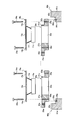
- FIG. 13A is a front view illustrating a configuration example of a unit including a housing and a speaker in the speaker array system according to the present embodiment.
- 13B is a top view of the unit of FIG. 13A
- FIG. 13C is a left side view of the unit of FIG. 13A
- FIG. 13D is a right side view of the unit of FIG. 13A.
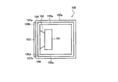
- the unit case 100 of the configuration example shown in FIGS. 13A to 13D is obtained by forming the unit case 20 of FIG. 1 into a sealed casing, and has an opening for connection to another unit case 100 in a cube. It has a shape with a part.
- the main body 100a, the diaphragm 102, the magnet 101, the flat surface portion 103, the female end 104 and the male end 105 of the unit casing are holes 106a and 106c, and the holes 106b and 106d are the main body in FIG. 21, the diaphragm 12, the flat portion 13, the female end 24, the male end 23, the hole 14, and the hole 15.
- the female end 104 and the male end 105 are provided in the opening for the connection, and the female end 104 and the male end 105 of the adjacent unit casings 100 are engaged by fitting or the like. Have a shape to do. Here, it is preferable that there is basically no gap when the shapes match each other.
- the female end 104 is provided with two unit casing fixing holes 109 corresponding to the unit casing fixing holes 27, and the male end 105 is provided with two unit casing fixing holes 25 corresponding to the unit casing fixing holes 25.
- Body fixing holes 107 a and 107 b and two unit housing fixing holes 108 corresponding to the unit fixing holes 26 are provided.
- FIGS. 14A to 14D An adjustment unit case applicable to such a sealed unit case 100 will be described with reference to FIGS. 14A to 14D and FIGS. 15A to 15D.
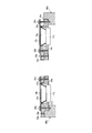
- 14A is a front view showing an example of the configuration of the unit housing for adjustment in the speaker array system according to the present embodiment
- FIG. 14B is a top view of the unit housing for adjustment in FIG. 14A
- FIG. 14C is for adjustment in FIG. 14A.
- FIG. 14D is a right side view of the unit housing for adjustment in FIG. 14A.
- 15A is a front view showing another configuration example of the unit housing for adjustment in the speaker array system according to the present embodiment
- FIG. 15B is a top view of the unit housing for adjustment in FIG. 15A
- FIG. 15C is FIG.
- FIG. 15D is a right side view of the adjustment unit casing of FIG. 15A.
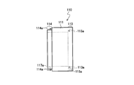
- 14A to 14D is an adjustment unit case 110 in which the adjustment unit case 80 shown in FIGS. 8 and 9 is formed into a hermetically sealed casing. It has a shape provided with an opening for connection with the unit housing 110 for adjustment. Further, as shown in the figure, the adjustment unit housing 110 has two openings, which are in communication with each other, so that the inside is hollow.
- the main body 111, the male end 113, and the female end 114 of the unit housing for adjustment correspond to the main body 81, the male end 83, and the female end 84 in FIG. 8, respectively.
- the male end 113 and the female end 114 are provided in the opening for the connection, and the male end 105 and the female end 104 (or other end of the unit casing 100 to be connected).
- the adjustment unit housing 110 has a male end 113 and a female end 114) which are engaged by fitting or the like.
- the tip of the male end 113 abuts on the stepped portion 114a of the female end 114, and the rear end of the female end 114 abuts on the stepped portion 113a of the male end 113.
- covers by comprising so that one opening part of the unit housing
- the female end 114 is provided with two unit casing fixing holes 117a and 117b corresponding to the unit casing fixing hole 87, and the male end 113 has two unit casing fixing holes 85 corresponding to the unit casing fixing hole 85.
- Unit housing fixing holes 115a and 115b are provided.
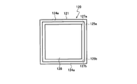
- 15A to 15D is an adjustment unit case 120 in which the adjustment unit case 80 shown in FIGS. 8 and 9 is formed into a hermetically sealed casing. It has a shape with an opening for connection with the adjustment unit housing 120. Further, as shown in the figure, the adjustment unit housing 120 has two openings, which are not in communication with each other, and a partition plate 128 is provided.
- the partition plate 128 is a partition that partitions the space in the adjustment unit casing.
- the main body 121, the male end 123, and the female end 124 of the unit housing for adjustment correspond to the main body 81, the male end 83, and the female end 84 in FIG. 8, respectively.
- the male end 123 and the female end 124 are provided in the opening for the connection, and the male end 105 and the female end 104 (or other end of the unit housing 100 to be connected).
- the adjustment unit housing 120 has a male end 123 and a female end 124) that are engaged by fitting or the like.
- the female end 124 is provided with two unit casing fixing holes 127a and 127b corresponding to the unit casing fixing hole 87, and the male end 123 has two unit casing fixing holes 85 corresponding to the unit casing fixing hole 85.
- Unit housing fixing holes 125a and 125b are provided.
- the internal space of the unit casings 100 connected to both sides can be partitioned by the partition plate 128. That is, with such a configuration, a space can be divided for each speaker body as a housing of the speaker array system. For example, it is possible to configure a resonance tube by providing a separate opening in each space.
- the adjustment unit housing 120 can be used as it is as a lid unit housing due to the presence of the partition plate 128, but it is changed to a shape in which one opening portion is covered to make a unit housing dedicated to the lid. You can also.
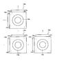
- FIG. 16 is a front view showing another configuration example of the speaker array system according to the present embodiment.
- the unit case 130a of the configuration example shown in FIG. 16 connects other unit cases, adjustment unit cases, and lid unit cases not only in the left-right direction but also in the vertical direction in the unit case 100 of FIG. 13A. It is possible. More specifically, in addition to attaching the female end 136a and the male end 137a of the unit housing 130a in the left-right direction on the paper surface, the unit casing 130a is expanded in the vertical direction by attaching the female end 134a and the male end 135a also in the vertical direction. Is.
- reference numeral 132a denotes a diaphragm.
- the unit casings 130b and 130c have the same configuration as the unit casing 130a.
- the reference numerals in the respective configurations of the unit casing 130a are changed from “a” to “b” or “c”. It is represented by Further, in FIG. 16, each hole for inserting the fixture is omitted, but it exists at least at the male end and the female end as in FIG. 13A and the like.
- the lower male end 135a of the unit housing 130a is inserted between the upper female end 134b of the unit housing 130b and the flat portion of the diaphragm 132b, and the right of the unit housing 130b is inserted.
- the male end 137b in the direction is inserted between the female end 136c in the left direction of the unit housing 130c and the flat portion of the diaphragm 132c.
- the unit cases 130a, 130b, and 130c can be connected.
- speaker array housings with various arrangements can be constructed, and thus speaker array systems with various arrangements can be constructed.
- the adjustment unit housings 110 and 120 can be appropriately sandwiched between the unit housings 130a and the like.
- the speaker array system is a speaker array system including a plurality of unit housings in which a speaker body for outputting an acoustic signal is fixed by a fixture, and the unit housings are connected to each other. They are connected to each other by the fixture.
- the speaker array system is a speaker array system including a plurality of unit housings each having a speaker main body for outputting an acoustic signal fixed by a fixture, and connecting the plurality of unit housings. And an adjustment unit housing for adjusting a distance between the unit housings, and the unit housings and / or the unit housing and the adjustment unit housing are connected to each other by the fixing tool. You may make it. Thereby, the distance between the speaker bodies can be arbitrarily changed.
- the adjustment unit housing may have a partition plate for partitioning the space in the adjustment unit housing. Thereby, space can be divided for every speaker main body as a housing
- a gasket for improving airtightness may be provided at a connection portion between the unit housings, or in order to improve airtightness at a connection portion between the unit housing and the adjustment unit housing.
- a gasket may be provided.
- Unit housing fixing hole 26... Unit fixing hole (unit housing fixing hole), 31, 31a, 32 33, 33a, 33z, 34a, 34z ... fixture, 40 ... gasket, 56a, 75, 75a ... unit fixing hole, 60a, 60z ... unit housing for lid, 61a ... main body of unit housing for lid, 64a, 64z ... Unit housing fixing holes of the unit housing for lid, 80, 80a, 80z, 110, 120 ... Unit housing for adjustment, 81, 111, 121 ... Main body of the unit housing for adjustment, 83, 113, 123 ... Adjustment Male end of unit housing 84, 114, 124 Female end of adjustment unit housing 85, 87 Unit housing fixing hole of adjustment unit housing 128 Partition plate
Landscapes
- Health & Medical Sciences (AREA)
- Otolaryngology (AREA)
- Physics & Mathematics (AREA)
- Engineering & Computer Science (AREA)
- Acoustics & Sound (AREA)
- Signal Processing (AREA)
- Details Of Audible-Bandwidth Transducers (AREA)
Abstract
複数のスピーカ本体を配列する際に簡易で少ない点数の部品で済み、且つスピーカ本体の配列個数を容易に変更することが可能なスピーカアレイシステムを提供する。本発明のスピーカアレイシステムは、音響信号を出力するためのスピーカ本体(10,10a,・・・)を備えると共に、それらを固定具(31,32)によって固定した複数の単位筐体(20,20a,・・・)を備え、上記単位筐体同士が、上記固定具によって互いに接続されている。
Description
本発明は、スピーカ本体を複数配列したスピーカアレイシステムに関する。
人間は、2つの耳に入る音の強度、時間などの違いによって、音が成す空間を知覚することができる。この音響空間を再現するもっとも単純なシステムとして、ステレオシステムが知られている。
ステレオシステムにおいては、視聴者の左右に設置したスピーカから出力する音の音圧や時間に差をつける(パニングする)ことで、音響空間を再現している。しかしながら、このステレオシステムにおいては、設置した左右のスピーカの中点と交わる中央線上においてのみ、略正確な音響空間が再現されるが、その位置(スイートスポットという)からずれた場合に、左右スピーカからの音の到達時間差や音圧差が変化してしまい、音響コンテンツ制作者の意図通りの音響空間が再現されないこととなる。また、5.1ch、7.1ch、9.1ch、22.2chなどの他のマルチチャネル再生方式も提案されているが、いずれもスイートスポット以外の位置で聴くと、一般的に音像・音質が劣化する。
このような課題を解決する手段として、例えば非特許文献1には、波面合成再生方式を用いたWave Field Synthesis(WFS)技術が提案されている。波面合成再生方式では、複数のスピーカをアレイ状(直線状あるいは曲線状)に並べたアレイスピーカ(スピーカアレイともいう)を用いて、夫々のスピーカからの音を重ね合わせることによって、仮想的に設定した仮想音像の位置から生じる波面を再現し、仮想音像位置に音像位置を知覚させる。
音楽コンテンツを例にとると、各仮想音源は、それぞれの楽器の音と楽器が配置されている位置情報とを含む。仮想音源それぞれの音声信号は必ずしも楽器毎である必要はないが、コンテンツ製作者が意図するそれぞれの音の到来方向と大きさが、仮想音源という概念を用いて表現されている必要がある。
この波面合成再生方式では、実空間で発生する波面と略同様の波面を再現するため、ステレオシステムとは異なり、所定の位置以外においても、意図した音響空間の音を視聴することができる。換言すれば、波面合成再生方式でのスイートスポットは広い領域となっている。
ところで、上述のような波面合成再生方式を利用するためには、アレイ状に複数のスピーカを配置しておく必要があり、そのための筺体が必要となる。
特許文献1には、このようなアレイスピーカ用の筺体が開示されている。特許文献1に記載の筐体は、アレイスピーカを取り付けるための略直方体のスピーカ筺体であって、両端に開口部とスピーカ筺体の内部空間を仕切る仕切り板を有している。この筐体は、両端に開口部を有することから仕切り板の位置に応じて形成された共鳴管の長さが変化するため、所定の共振周波数の音圧レベルを強調することが可能になっている。
特許文献1には、このようなアレイスピーカ用の筺体が開示されている。特許文献1に記載の筐体は、アレイスピーカを取り付けるための略直方体のスピーカ筺体であって、両端に開口部とスピーカ筺体の内部空間を仕切る仕切り板を有している。この筐体は、両端に開口部を有することから仕切り板の位置に応じて形成された共鳴管の長さが変化するため、所定の共振周波数の音圧レベルを強調することが可能になっている。
また、特許文献2に記載の筐体は、スピーカを取り付けるスピーカ取付具と、所定数のスピーカ取付具を配列して取り付けるための筐体本体とを備えている。この筐体を備えたスピーカアレイシステムでは、スピーカ取付具同士を突起と溝とで係合させた状態で配列し、スピーカとスピーカ取付具とを取り付けるネジで筐体本体にネジ止めされている。
A. J. Berkhout, D. de Vries, and P. Vogel, "Acoustic control by wave field synthesis", J. Acoust. Soc. Am. Volume 93(5), アメリカ合衆国, Acoustical Society of America, May 1993, pp. 2764-2778
特許文献1に記載のアレイスピーカ用筐体にその筐体に合った個数のスピーカ本体を取り付けることによって、波面合成再生方式で音響コンテンツの再生が可能なスピーカアレイシステムを提供できる。
しかしながら、アレイスピーカ用筺体に求められる幅や長さ、換言すれば必要とされるスピーカ本体の個数は必ずしも一定ではない。例えば、テレビ装置にこのようなスピーカアレイシステムを搭載することを考える。40インチのテレビ装置(アスペクト比は16:9とする)においては、ディスプレイ面の横幅は約88.6cmである。一方、52インチのテレビ装置においては、ディスプレイ面の横幅は約115.1cmである。ここで、40インチのテレビ装置にマッチしたスピーカアレイシステムを52インチのテレビ装置に搭載した場合、再現される音響空間が狭く感じられてしまう。テレビ装置のサイズが小さくなる場合も同様に再現される音響空間が合わず、受聴者に違和感を与えてしまう。
このような問題は、設置する機器に応じた幅の持つようにスピーカアレイシステムを複数種類用意すれば解決しうるが、ラインナップの数が多くなり、アレイスピーカ用筺体を生成するための金型の数が増えてしまうなど、大きなコストアップにつながってしまう。
このように、特許文献1に記載のスピーカアレイシステムは、アレイスピーカの幅や長さを容易に変更することができない。
なお、複数のスピーカ本体をアレイ状(もしくはマトリクス状)に配置するためには、特許文献1に記載のような開口部および仕切り板は必須とは言えない。
なお、複数のスピーカ本体をアレイ状(もしくはマトリクス状)に配置するためには、特許文献1に記載のような開口部および仕切り板は必須とは言えない。
一方で、特許文献2に記載のスピーカ取付具は、スピーカ本体を取り付けるネジによって筐体本体側に取り付けられる上に、取り付ける機器側の筐体本体の設計を変更することで任意にスピーカ本体の個数を変更することができる。
しかしながら、特許文献2に記載のスピーカ取付具では、スピーカ取付具を複数繋げてアレイスピーカを構成してから機器側の筐体本体にそのアレイスピーカを取り付けることができず、機器側に個々にスピーカ取付具を取り付けていく必要があり、作業に手間がかかる上に、スピーカ取付具の構造が複雑なものとなっている。
しかしながら、特許文献2に記載のスピーカ取付具では、スピーカ取付具を複数繋げてアレイスピーカを構成してから機器側の筐体本体にそのアレイスピーカを取り付けることができず、機器側に個々にスピーカ取付具を取り付けていく必要があり、作業に手間がかかる上に、スピーカ取付具の構造が複雑なものとなっている。
本発明は、上述のような実状に鑑みてなされたものであり、その目的は、複数のスピーカ本体を配列する際に簡易で少ない点数の部品で済み、且つスピーカ本体の配列個数を容易に変更することが可能なスピーカアレイシステムを提供することにある。
上記の課題を解決するために、本発明の第1の技術手段は、音響信号を出力するためのスピーカ本体を固定具によって固定した単位筐体を、複数備えたスピーカアレイシステムであって、前記単位筐体同士が、前記固定具によって互いに接続されていることを特徴としたものである。
本発明の第2の技術手段は、音響信号を出力するためのスピーカ本体を固定具によって固定した単位筐体を、複数備えたスピーカアレイシステムであって、複数の前記単位筺体を接続する際に、前記単位筺体間の距離を調整するための調整用単位筺体をさらに備え、前記単位筐体同士、および/または、前記単位筺体と前記調整用単位筺体が、前記固定具によって互いに接続されていることを特徴としたものである。
本発明の第3の技術手段は、第2の技術手段において、前記調整用単位筺体は、前記調整用単位筺体内の空間を仕切るための仕切り板を有することを特徴としたものである。
本発明の第4の技術手段は、第1~第3のいずれか1の技術手段において、前記単位筐体同士の接続部分に、気密性を高めるためのガスケットを設けたことを特徴としたものである。
本発明の第5の技術手段は、第2または第3の技術手段において、前記単位筐体と前記調整用単位筐体との接続部分に、気密性を高めるためのガスケットを設けたことを特徴としたものである。
本発明のスピーカアレイシステムによれば、複数のスピーカ本体を配列する際に簡易で少ない点数の部品で済み、且つスピーカ本体の配列個数を容易に変更することが可能になる。
本発明に係るスピーカアレイシステムは、音響信号を出力するためのスピーカ本体を備えると共に、そのスピーカ本体を1または複数固定するための単位筐体を複数備えたシステムである。各スピーカ本体は配線により、音声信号再生装置に接続され、そこで再生された音声信号を各スピーカ本体から音として出力することができる。また、このような音声信号再生装置およびスピーカアレイシステムは、テレビ装置などの様々なAV機器に搭載可能である。
以下、本発明に係る実施形態を、図面を参照して説明する。なお、音声信号再生装置やAV機器等については、本発明の主たる特徴と基本的に関係ないため、以下では特に説明しない。
(第1の実施形態)
図1および図2は、本実施形態に係るスピーカアレイシステムの一構成例を示す図で、図1は組み立て前の状態(スピーカ本体取付面の状態)を示す断面図、図2は図1の状態から組み立てを行った後の状態を示す断面図である。
本実施形態において、スピーカアレイシステムは、例えば図1に示すように、スピーカ本体10、単位筐体20、およびネジ等の固定具31,32を備える。
図1および図2は、本実施形態に係るスピーカアレイシステムの一構成例を示す図で、図1は組み立て前の状態(スピーカ本体取付面の状態)を示す断面図、図2は図1の状態から組み立てを行った後の状態を示す断面図である。
本実施形態において、スピーカアレイシステムは、例えば図1に示すように、スピーカ本体10、単位筐体20、およびネジ等の固定具31,32を備える。
スピーカ本体10は、コーン型のスピーカであり、主にコーン型振動板12およびその駆動機構をなす磁石11と、図示しない配線等で構成される。なお、スピーカ本体とは、基本的にスピーカ装置において筐体を除いた部分、もしくはそのうち音を発する部分(主に振動板とその駆動機構)を指し、スピーカユニットとも呼べる。
コーン型振動板12の平面部13には固定具31,32を挿入するための孔14,15が設けられている。孔14,15で図示した孔は、振動板12の平面部13の4箇所(四隅)に設けられており、固定具31,32も1つのスピーカ本体10につき合計4つとなる。また、孔14,15をはじめ、以下に説明する孔のうち、固定具31,32等で固定するための孔は、その固定具に合った形状をもち、例えば固定具31がネジであれば孔14等もネジに合った形状に穿たれているか、ネジをねじ込むことが可能な固さを持つ。
また、スピーカ本体10として通常のコーン型のスピーカを挙げて説明しているが、これに限ったものではない。例えば、コーン型振動板の中央に小口径のコーン型振動板を取り付けたダブルコーン型振動板を用いたスピーカ、ホーン型スピーカ、ドーム型スピーカなどであってもよく、さらには振動板がリボン型で且つその周囲に設けた枠をネジ止めするようなスピーカであってもよい。
単位筺体20は、スピーカ本体10を固定するための筐体であり、本体21の中央部分にスピーカ本体10の振動板12の部分を収容するための孔22が設けられている。この単位筐体20は、スピーカユニット用単位筐体と呼べる。
そして、本実施形態の主たる特徴として、単位筐体同士(例えば単位筐体20と単位筐体20a)を、単位筐体に対してスピーカ本体を固定するための固定具(例えば固定具32)によって接続している。つまり、本実施形態のスピーカアレイシステムは、音響信号を出力するためのスピーカ本体を固定具によって固定した単位筐体を複数備えており、これら単位筐体同士が、上記固定具によって互いに接続されている。
より具体的に説明すると、単位筐体20の本体21の両端には、隣りに配する単位筐体(この例では単位筐体20a)と接続できるように、上部(平面部13側)が突出した部位である雄端23と下部が突出した部位である雌端24とが設けられている。また、単位筐体20には、スピーカ本体10を固定するためのユニット固定孔26が設けられると共に、隣り合わせる単位筐体20aを固定するために雄端23、雌端24にそれぞれ単位筺体固定孔25,27が設けられている。なお、ユニット固定孔26は、スピーカ本体10がスピーカユニットと呼べるため、このような名称で呼んでいる。
なお、スピーカ本体10aは、スピーカ本体10と同じ構成であり、磁石11aと、孔14a,15aが穿たれた平面部13aを持つコーン型振動板12aと、図示しない配線等で構成される。また、単位筐体20aは、単位筐体20と同じ構成であり、本体21aの中央部分に孔22aが設けられ、両端には単位筐体固定孔25aが穿たれた雄端23aおよび単位筐体固定孔27aが穿たれた雌端24aが設けられ、本体21aの孔22aと単位筐体固定孔25aとの間にはユニット固定孔26aが設けられている。単位筐体20bも同様の構成であり、ここでは、単位筐体20aの各構成における符号の末尾を「a」から「b」に変えた符号で表している。
このような構成の単位筐体20とスピーカ本体10とを複数セット繋げる際には、図1で示すように単位筐体20の雌端24と単位筐体20aの雄端23aとを重ね、その上からスピーカ本体10と共に固定具32で固定する。具体的には固定具32を、スピーカ本体10の孔15および単位筐体20aの単位筐体固定孔25aを介して、単位筐体20の単位筐体固定孔27に固定する。スピーカ本体10の他端側は、固定具31を、スピーカ本体10の孔14を介して単位筐体20のユニット固定孔26に固定する。
このような固定作業により、図2に示すように隣り合う単位筺体20,20a同士を、スピーカ本体10を単位筐体20に固定するための固定具31,32で固定することができる。そして、このようなセットを必要な数だけ繋ぎ合わせ、任意の数のスピーカアレイ用筺体を構成することができ、任意の幅(および長さ)のスピーカアレイシステムを構成することができる。
なお、本構成例および後述する他の構成例では、孔14,15は1つの振動板12につき4箇所に限らず、2箇所などであってもよいが、上述のように単位筐体同士をスピーカ本体10用の固定具31,32によって固定するものとする。
また、本構成例および後述する他の構成例では、スピーカ本体10を取り付ける単位筺体20,20a,20bの形状を平面バッフル状に表現しているが、例えば、密閉型、バスレフ型、バックロードホーン型など、いずれの形状であってもよく、平面であることに限定はしない。なお、このうち密閉型については第4の実施形態で後述する。
次に、図3を参照しながら他の構成例について説明する。図3は、本実施形態に係るスピーカアレイシステムの他の構成例を示す断面図である。
図3に示すように、単位筐体同士の接続部分(接合部分)にガスケット40を別途取り付けてもよい。これにより、アレイスピーカ用筐体全体(スピーカアレイシステム)としての気密性を高めることができる。
図3に示すように、単位筐体同士の接続部分(接合部分)にガスケット40を別途取り付けてもよい。これにより、アレイスピーカ用筐体全体(スピーカアレイシステム)としての気密性を高めることができる。
このようなガスケット40は、後述する他の構成例においても適用できる。また、ガスケット40としては、雄端23、雌端24のいずれか一方または双方にガスケットとして利用可能な材料を塗布しておくことで組み立て工程を削減するようにしてもよい。
図4,図5を参照しながら他の構成例について説明する。図4および図5は、本実施形態に係るスピーカアレイシステムの他の構成例を示す図で、図4は組み立て前の状態を示す断面図、図5は図4の状態から組み立てを行った後の状態を示す断面図である。
図1,図2で説明した単位筐体20を単に繋げていくだけでは、両端部分が解放され、筺体が密閉されない。そこで、図4,図5に示すように蓋用単位筺体60aおよびそれと同様の構成(但し左右は逆)の蓋用単位筐体60zを用いて、両端部分を閉じるように構成することもできる。
蓋用単位筐体60aは、単位筐体20aの本体21aと雄端23aの形状に合うように、本体61aの上端部62aに段差部63aが設けられており、その段差部63aには単位筐体20aを固定具33aにより固定するための単位筐体固定孔64aが設けられている。また、図1のユニット固定孔26の代わりに、貫通するユニット固定孔56aが本体21aに設けられている。固定具33a、および固定具34a,33z,34zは、固定具31,32と同様の構成であり、固定具33a,34zは長めに形成されている。なお、単位筐体固定孔64aは蓋用単位筺体60aを貫通するように設けてもよい。
なお、図4,図5において、蓋用単位筐体60zは、蓋用単位筐体60aと同様の構成であり、ここでは、蓋用単位筐体60aの各構成における符号の末尾を「a」から「z」に変えた符号で表している。スピーカ本体10zは、スピーカ本体10aと同じ構成であり、ここでは、スピーカ本体10aの各構成における符号の末尾を「a」から「z」に変えた符号で表している。単位筐体20zは、単位筐体20aと同じ構成であり、ここでは、単位筐体20aの各構成における符号の末尾を「a」から「z」に変えた符号で表している。
このような構成の単位筐体20aとスピーカ本体10aと蓋用単位筐体60aとを接続する際には、図4で示すように単位筐体20aの雄端23aと蓋用単位筐体60aの上端部62aとを重ねると共に、本体21aと段差部63aとを重ね、その上からスピーカ本体10aと共に固定具33aで固定する。具体的には固定具33aを、スピーカ本体10aの孔14aおよび単位筐体20aのユニット固定孔56aを介して、蓋用単位筐体60aの単位筐体固定孔64aに固定する。スピーカ本体10aの他端側は、図1,図2で説明したように、固定具34aを、スピーカ本体10aの孔15aおよび隣りの単位筐体の単位筐体固定孔を介して、単位筐体20aの単位筐体固定孔57aに固定する。
また、単位筐体20zとスピーカ本体10zと蓋用単位筐体60zとを接続する際には、図4で示すように単位筐体20zの雌端24zと蓋用単位筐体60zの段差部63zとを重ね、その上からスピーカ本体10zと共に固定具34zで固定する。具体的には固定具34zを、スピーカ本体10zの孔15zおよび単位筐体20zの単位筐体固定孔57zを介して、蓋用単位筐体60zの単位筐体固定孔64zに固定する。このとき、平面部13zと雌端24zとの間には固定具34z以外の部分で空隙が生じる。但し、この空隙を埋めるように蓋用単位筐体60zを構成してもよい。
このような固定作業により、図5に示すように、スピーカ本体10を単位筐体20に固定するための固定具33a,34a等で、単位筺体20a,・・・,20zを隣り合う同士で固定すると共に、両端を蓋用単位筐体60a,60zで固定することができる。
図6,図7を参照しながら他の構成例について説明する。図6および図7は、本実施形態に係るスピーカアレイシステムの他の構成例を示す図で、図6は組み立て前の状態を示す断面図、図7は図6の状態から組み立てを行った後の状態を示す断面図である。
図6で例示する構成例の単位筐体20は、雄端23において、図1の単位筐体固定孔25、ユニット固定孔26の代わりに2つの単位筐体固定孔25,26が設けられており、図6における単位筐体固定孔26は貫通孔となっている。また、図6の単位筐体20は、雌端24においても、図1の単位筐体固定孔27の他にもう1つの単位筐体固定孔28が設けられている。
このような構成の単位筐体20とスピーカ本体10とを複数セット繋げる際には、図6で示すように単位筐体20の雌端24と単位筐体20aの雄端23aとを重ね、その上からスピーカ本体10の右端側およびスピーカ本体10aの左端側と共に固定具32,31aで固定する。具体的には固定具32を、孔15および単位筐体固定孔25aを介して単位筐体固定孔27に固定し、固定具31aを、孔14aおよび単位筐体固定孔26aを介して単位筐体固定孔28に固定する。スピーカ本体10の他端側は、固定具31を、孔14を介してユニット固定孔26に固定する。
このような固定作業により、図7に示すように隣り合う単位筺体20,20a同士を、スピーカ本体10,10aを単位筐体20,20aに固定するための固定具32,31aで固定することができる。なお、図7において、23cは左端側の単位筐体における雄端を示し、31cは左端側のスピーカ本体を固定するための固定具を示し、24dは右端側の単位筐体における雌端を示している。
なお、以上の構成例および後述の構成例においては、単位筺体の接合部(雌端、雄端)は腰掛型にしてあるが、例えば凹凸、継木、仕口のように他の形状を採用してもよく、単純な腰掛型に限定されるものではない。但し、両者の形状が合い、合わさった際に基本的に隙間が生じないことが好ましい。
以上のように、本実施形態によれば、スピーカ本体を取り付ける筺体を単位筺体にし(スピーカ本体用の固定筐体を単位化し)、任意の個数接合できるようにすると共に、単位筐体同士の接合をスピーカ本体の固定具と統一化することで、アレイ化した際のスピーカアレイの幅(や長さ)を任意に且つ容易に変更することができるようになる。また、効率的に接合することによって、部品点数を削減することができ、いずれの部品の構成も複雑なものにしなくて済む。さらに、スピーカ本体を固定した単位筐体を接続することでスピーカアレイシステムを構築してから、AV機器にそのシステムを搭載することができるため、作業効率が良くなる。
(第2の実施形態)
図8および図9は、本実施形態に係るスピーカアレイシステムの一構成例を示す図で、図8は組み立て前のスピーカ本体取付面の状態を示す断面図、図9は図8の状態から組み立てを行った後の状態を示す断面図である。
図8および図9は、本実施形態に係るスピーカアレイシステムの一構成例を示す図で、図8は組み立て前のスピーカ本体取付面の状態を示す断面図、図9は図8の状態から組み立てを行った後の状態を示す断面図である。
第1の実施形態のスピーカアレイシステムは、スピーカ本体間の距離が一定となってしまうという。これに対し、本実施形態では、スピーカ本体間の距離を変える(換言すればスピーカ本体の個数を同じにしてスピーカアレイの幅を変える)ことが可能な構成例を説明する。
本実施形態の主たる特徴として、単位筐体同士(例えば単位筐体70と単位筐体70a)を、および/または単位筐体70,70aと調整用単位筐体80を、単位筐体に対してスピーカ本体10,10aを固定するための固定具(例えば固定具32)によって接続している。つまり、本実施形態のスピーカアレイシステムは、音響信号を出力するためのスピーカ本体10を固定具31,32によって固定した単位筐体を複数備え、且つ調整用単位筺体を1または複数備えており、これら単位筐体同士が、および/または、単位筺体と調整用単位筺体が、上記固定具によって互いに接続されている。
より具体的に説明すると、スピーカ本体10,10a間の距離を変えるために、図8で示すように、単位筐体70と単位筐体70aとの間に調整用単位筐体80を設けている。調整用単位筺体80は、複数の単位筐体を接続する際に単位筐体間の距離を調整するための筐体であり、マージン用単位筐体ともいう。なお、単位筐体70,70aは、図1における単位筐体20,20aと同じ構成であり、ここでは図1における20番台の符号を70番台で表している。
調整用単位筐体80は、単位筐体70と調整用単位筺体80とを、スピーカ本体10用の固定具32によって固定することが可能になっている。そのため、調整用単位筐体80は、本体81に雄端73、雌端84とそれぞれ同じ構成の雄端83、雌端84が設けられ、雄端83には貫通孔である単位筐体固定孔85が設けられ、雌端84には非貫通孔または貫通孔である単位筐体固定孔87が設けられている。なお、図8,図9において、調整用単位筐体80aは、調整用単位筐体80と同じ構成であり、ここでは、調整用単位筐体80の各構成における符号の末尾に「a」を付した符号で表している。
このような構成の単位筐体70とスピーカ本体10と調整用単位筐体80と単位筐体70aとを繋げる際には、図8で示すように単位筐体70の雌端74と調整用単位筐体80の雄端83とを重ね、その上からスピーカ本体10の右端側と共に固定具32で固定する。具体的には固定具32を、孔15および単位筐体固定孔85を介して単位筐体固定孔77に固定する。スピーカ本体10の他端側は、固定具31を、孔14を介してユニット固定孔75に固定する。調整用単位筐体80の雌端84は、同様に、固定具31aを、孔14aおよびユニット固定孔75aを介して単位筐体固定孔87に固定する。
このような固定作業により、図9に示すように単位筺体20,20a同士を、調整用単位筐体80を介し、スピーカ本体10,10aを単位筐体20,20aに固定するための固定具32,31aで固定することができる。なお、図9において、83cは左端側の調整用単位筐体における雄端を示し、84dは右端側の調整用単位筐体における雌端を示している。また、単位筺体20,20a同士を直接接続する箇所が存在してもよく、その接続方法については第1の実施形態で説明した通りである。
以上、本実施形態によれば、第1の実施形態と同様の効果に加え、スピーカ本体間の距離を任意に変えることが可能になる。基本的にスピーカ本体間の距離は等距離であることが音声信号の制御上好ましいことが多いが、距離を変える場合もあり、本実施形態はそのような場合に特に有益となる。また、図示しないが、単位筐体と調整用単位筐体との接続部分にも、図3で例示したようなガスケット40を設けておくことが好ましい。
図10を参照しながら、本実施形態の他の構成例について説明する。図10は、本実施形態に係るスピーカアレイシステムの他の構成例を示す断面図である。
図10に示すように、調整用単位筐体80a(およびそれと同様の構成の調整用単位筐体80z)を第1の実施形態における蓋用単位筐体として利用することもできる。但し、調整用単位筐体80a,80zは、端部に設けられるため、それに見合った構造を持つものとする。例えば、後述する密閉型においては仕切りを有する筐体とする。
図10に示すように、調整用単位筐体80a(およびそれと同様の構成の調整用単位筐体80z)を第1の実施形態における蓋用単位筐体として利用することもできる。但し、調整用単位筐体80a,80zは、端部に設けられるため、それに見合った構造を持つものとする。例えば、後述する密閉型においては仕切りを有する筐体とする。
なお、図10において、84yは調整用単位筐体の雌端を示している。調整用単位筐体80zは、調整用単位筐体80aと同じ構成であり、ここでは、調整用単位筐体80aの各構成における符号の末尾を「a」から「z」に変えた符号で表している。単位筐体70yは、単位筐体70aと同じ構成であり、ここでは、単位筐体70aの各構成における符号の末尾を「a」から「y」に変えた符号で表している。スピーカ本体10yは、スピーカ本体10aと同じ構成であり、ここでは、スピーカ本体10aの各構成における符号の末尾を「a」から「y」に変えた符号で表している。また、符号31y、32yは固定具を示している。
このような構成の単位筐体70aとスピーカ本体10aと調整用単位筐体(蓋用単位筐体)80aとを接続する際、並びに単位筐体70yとスピーカ本体10yと調整用単位筐体(蓋用単位筐体)80zとを接続する際には、図5を参照した蓋用単位筐体60a,60zとの接続と同様に行えばよい。
(第3の実施形態)
本実施形態として、単位筐体の他の構成例、並びに調整用単位筐体の他の使用方法について、それぞれ図11、図12を参照しながら説明する。図11、図12は、それぞれ本実施形態に係るスピーカアレイシステムの一構成例を示す断面図である。
本実施形態として、単位筐体の他の構成例、並びに調整用単位筐体の他の使用方法について、それぞれ図11、図12を参照しながら説明する。図11、図12は、それぞれ本実施形態に係るスピーカアレイシステムの一構成例を示す断面図である。
図11に示す構成例の単位筐体90は、図1の単位筐体20と異なり、孔22に対応する孔92aの他にもう1つの孔92bを備え、設置可能なスピーカ本体の個数を2つとしている。このように、単位筐体は2つ以上のスピーカ本体が搭載可能なように構成することもできる。
図12に示す構成例のスピーカアレイシステムでは、調整用単位筐体80と調整用単位筐体80aを固定具33により連結させ、単位筐体70と単位筐体70aの間に設けている。このように、単位筐体間には調整用単位筐体を複数連結させたものを設けてもよい。
(第4の実施形態)
本実施形態として、密閉型の筐体について説明する。なお、本実施形態においても基本的に第1の実施形態と同様の効果を奏する。
本実施形態として、密閉型の筐体について説明する。なお、本実施形態においても基本的に第1の実施形態と同様の効果を奏する。
まず、密閉型の単位筐体について、図13A~図13Dを参照しながら説明する。図13Aは、本実施形態に係るスピーカアレイシステムにおける筐体およびスピーカでなるユニットの一構成例を示す正面図である。また、図13Bは図13Aのユニットの上面図、図13Cは図13Aのユニットの左面図、図13Dは図13Aのユニットの右面図である。
図13A~図13Dに示す構成例の単位筐体100は、図1の単位筐体20を、密閉型の筺体にしたものであり、立方体において他の単位筐体100との接続のための開口部を備える形状を持つ。
図13A~図13Dにおいて、単位筐体の本体100a、振動板102、磁石101、平面部103、雌端104、雄端105は、孔106a,106c、孔106b,106dは、それぞれ図1における本体21、振動板12、平面部13、雌端24、雄端23、孔14、孔15に相当する。
単位筐体100において雌端104、雄端105は、上記接続のための開口部に設けられており、隣接する単位筐体100同士の雌端104と雄端105とは嵌合等により係合する形状を持つ。ここで、互いの形状が合い、合わさった際に基本的に隙間が生じないことが好ましい。また、雌端104には、単位筐体固定孔27に相当する2つの単位筐体固定孔109が設けられており、雄端105には、単位筐体固定孔25に相当する2つの単位筐体固定孔107a,107bと、ユニット固定孔26に相当する2つのユニット筐体固定孔108とが設けられている。
このような密閉型の単位筐体100に適用できる調整用単位筐体について、図14A~図14D、図15A~図15Dを参照しながら説明する。図14Aは本実施形態に係るスピーカアレイシステムにおける調整用単位筐体の一構成例を示す正面図で、図14Bは図14Aの調整用単位筐体の上面図、図14Cは図14Aの調整用単位筐体の左面図、図14Dは図14Aの調整用単位筐体の右面図である。また、図15Aは本実施形態に係るスピーカアレイシステムにおける調整用単位筐体の他の構成例を示す正面図で、図15Bは図15Aの調整用単位筐体の上面図、図15Cは図15Aの調整用単位筐体の左面図、図15Dは図15Aの調整用単位筐体の右面図である。
図14A~図14Dに示す構成例の調整用単位筐体110は、図8,図9の調整用単位筐体80を、密閉型の筺体にしたものであり、立方体において単位筐体100または他の調整用単位筐体110との接続のための開口部を備える形状を持つ。さらに調整用単位筐体110は、図示するように、この開口部が2つ存在し、それらが連通しており、それにより内部が空洞になっている。
図14A~図14Dにおいて、調整用単位筐体の本体111、雄端113、雌端114は、それぞれ図8における本体81、雄端83、雌端84に相当する。調整用単位筐体110において雄端113、雌端114は、上記接続のための開口部に設けられており、それぞれ接続対象となる単位筐体100の雄端105、雌端104(あるいは他の調整用単位筐体110の雄端113、雌端114)とは嵌合等により係合する形状を持つ。
調整用単位筐体110同士を接続する場合には、雌端114の段差部114aに雄端113の先端が当接し、雄端113の段差部113aに雌端114の後端が当接することになる。また、調整用単位筐体110の1つの開口部を閉じるように構成することで、蓋用単位筐体として利用することができる。また、雌端114には、単位筐体固定孔87に相当する2つの単位筐体固定孔117a,117bが設けられており、雄端113には、単位筐体固定孔85に相当する2つの単位筐体固定孔115a,115bが設けられている。
図15A~図15Dに示す構成例の調整用単位筐体120は、図8,図9の調整用単位筐体80を、密閉型の筺体にしたものであり、立方体において単位筐体100または他の調整用単位筐体120との接続のための開口部を備える形状を持つ。さらに調整用単位筐体120は、図示するように、この開口部が2つ存在し、それらが連通しておらず、仕切り板128が設けられている。仕切り板128は、調整用単位筺体内の空間を仕切る間仕切りである。
図15A~図15Dにおいて、調整用単位筐体の本体121、雄端123、雌端124は、それぞれ図8における本体81、雄端83、雌端84に相当する。調整用単位筐体120において雄端123、雌端124は、上記接続のための開口部に設けられており、それぞれ接続対象となる単位筐体100の雄端105、雌端104(あるいは他の調整用単位筐体120の雄端123、雌端124)とは嵌合等により係合する形状を持つ。
調整用単位筐体120同士を接続する場合には、雌端124の段差部124aに雄端123の先端が当接し、雄端123の段差部123aに雌端124の後端が当接することになる。また、雌端124には、単位筐体固定孔87に相当する2つの単位筐体固定孔127a,127bが設けられており、雄端123には、単位筐体固定孔85に相当する2つの単位筐体固定孔125a,125bが設けられている。
仕切り板128により、両側に接続される単位筐体100同士の内部空間を仕切ることができる。つまり、このような構成により、スピーカアレイシステムの筐体として、スピーカ本体毎に空間を分けることができる。例えば、各空間に別途開口部を設けることで共鳴管を構成することもできる。また、調整用単位筐体120は仕切り板128の存在によりそのまま蓋用単位筐体として利用することができるが、1つの開口部に蓋をした形状に変更し蓋専用の単位筐体とすることもできる。
次に、図16を参照しながらさらに他の構成例について説明する。図16は、本実施形態に係るスピーカアレイシステムの他の構成例を示す正面図である。
図16に示す構成例の単位筐体130aは、図13Aの単位筐体100において、左右方向だけでなく上下方向にも他の単位筐体や調整用単位筐体や蓋用単位筐体を接続可能なようにしている。より具体的には、単位筐体130aの雌端136a、雄端137aを紙面の左右方向に付けるだけでなく、雌端134a、雄端135aを上下方向にも付けることによって上下方向にも拡張したものである。
図16に示す構成例の単位筐体130aは、図13Aの単位筐体100において、左右方向だけでなく上下方向にも他の単位筐体や調整用単位筐体や蓋用単位筐体を接続可能なようにしている。より具体的には、単位筐体130aの雌端136a、雄端137aを紙面の左右方向に付けるだけでなく、雌端134a、雄端135aを上下方向にも付けることによって上下方向にも拡張したものである。
なお、図16において、132aは振動板を示している。また、単位筐体130b,130cは、単位筐体130aと同じ構成であり、ここでは、単位筐体130aの各構成における符号の末尾を「a」から「b」や「c」に変えた符号で表している。また、図16において、固定具を挿入する各孔については省略しているが、図13A等と同様に少なくとも雄端と雌端において存在する。
図16の構成例では、単位筐体130aの下方向の雄端135aを単位筐体130bの上方向の雌端134bと振動板132bの平面部との間に挿入し、単位筐体130bの右方向の雄端137bを単位筐体130cの左方向の雌端136cと振動板132cの平面部との間に挿入する。これにより、単位筐体130a,130b,130cを接続することができる。このようにして、様々な配列(幅や長さ)のスピーカアレイ筐体を構築でき、もって様々な配列のスピーカアレイシステムを構築することができる。例えば、適宜、調整用単位筐体110,120を単位筐体130a等の間に挟むこともできる。
以上のように、本発明に係るスピーカアレイシステムは、音響信号を出力するためのスピーカ本体を固定具によって固定した単位筐体を、複数備えたスピーカアレイシステムであって、前記単位筐体同士が、前記固定具によって互いに接続されていることを特徴としたものである。これにより、複数のスピーカ本体を配列する際に簡易で少ない点数の部品で済み、且つスピーカ本体の配列個数を容易に変更することが可能になる。
また、本発明に係るスピーカアレイシステムは、音響信号を出力するためのスピーカ本体を固定具によって固定した単位筐体を、複数備えたスピーカアレイシステムであって、複数の前記単位筺体を接続する際に、前記単位筺体間の距離を調整するための調整用単位筺体をさらに備え、前記単位筐体同士、および/または、前記単位筺体と前記調整用単位筺体が、前記固定具によって互いに接続されているようにしてもよい。これにより、スピーカ本体間の距離を任意に変えることが可能になる。
また、前記調整用単位筺体は、前記調整用単位筺体内の空間を仕切るための仕切り板を有するようにしてもよい。これにより、スピーカアレイシステムの筐体として、スピーカ本体毎に空間を分けることができる。
また、前記単位筐体同士の接続部分に、気密性を高めるためのガスケットを設けるようにしてもよいし、前記単位筐体と前記調整用単位筐体との接続部分に、気密性を高めるためのガスケットを設けるようにしてもよい。これにより、スピーカアレイシステムの筐体としての気密性を高めることができる。
上述した様々な実施形態において、添付図面に図示されている構成等については、あくまで一例であり、これらに限定されるものではなく、本発明の効果を発揮する範囲内で適宜変更することが可能である。その他、本発明の目的の範囲を逸脱しない限りにおいて適宜変更して実施することが可能である。
10,10a,10y,10z…スピーカ本体、11,101…磁石、12,102…振動板、13,13a,13z,103…平面部、14,15,14a,15a…孔、20,20a,20b,70,70a,70y,90,100,130a,130b,130c…単位筺体(スピーカユニット用単位筐体)、21,21a,100a…単位筐体の本体、22,22a,92a,92b…スピーカ本体収容のための孔、23,23a,73,105,135a,137a,137b…雄端、24,24a,24z,74,104,134a,134b,136a,136c…雌端、25,25a,26a,27,27a,28,57a,57z,77…単位筺体固定孔、26…ユニット固定孔(単位筐体固定孔)、31,31a,32,33,33a,33z,34a,34z…固定具、40…ガスケット、56a,75,75a…ユニット固定孔、60a,60z…蓋用単位筐体、61a…蓋用単位筐体の本体、64a,64z…蓋用単位筐体の単位筐体固定孔、80,80a,80z,110,120…調整用単位筐体、81,111,121…調整用単位筐体の本体、83,113,123…調整用単位筐体の雄端、84,114,124…調整用単位筐体の雌端、85,87…調整用単位筐体の単位筐体固定孔、128…仕切り板。
Claims (5)
- 音響信号を出力するためのスピーカ本体を固定具によって固定した単位筐体を、複数備えたスピーカアレイシステムであって、
前記単位筐体同士が、前記固定具によって互いに接続されていることを特徴とするスピーカアレイシステム。 - 音響信号を出力するためのスピーカ本体を固定具によって固定した単位筐体を、複数備えたスピーカアレイシステムであって、
複数の前記単位筺体を接続する際に、前記単位筺体間の距離を調整するための調整用単位筺体をさらに備え、
前記単位筐体同士、および/または、前記単位筺体と前記調整用単位筺体が、前記固定具によって互いに接続されていることを特徴とするスピーカアレイシステム。 - 前記調整用単位筺体は、前記調整用単位筺体内の空間を仕切るための仕切り板を有することを特徴とする請求項2に記載のスピーカアレイシステム。
- 前記単位筐体同士の接続部分に、気密性を高めるためのガスケットを設けたことを特徴とする請求項1~3のいずれか1項に記載のスピーカアレイシステム。
- 前記単位筐体と前記調整用単位筐体との接続部分に、気密性を高めるためのガスケットを設けたことを特徴とする請求項2または3に記載のスピーカアレイシステム。
Applications Claiming Priority (2)
| Application Number | Priority Date | Filing Date | Title |
|---|---|---|---|
| JP2013091255 | 2013-04-24 | ||
| JP2013-091255 | 2013-04-24 |
Publications (1)
| Publication Number | Publication Date |
|---|---|
| WO2014174992A1 true WO2014174992A1 (ja) | 2014-10-30 |
Family
ID=51791574
Family Applications (1)
| Application Number | Title | Priority Date | Filing Date |
|---|---|---|---|
| PCT/JP2014/059248 Ceased WO2014174992A1 (ja) | 2013-04-24 | 2014-03-28 | スピーカアレイシステム |
Country Status (1)
| Country | Link |
|---|---|
| WO (1) | WO2014174992A1 (ja) |
Citations (4)
| Publication number | Priority date | Publication date | Assignee | Title |
|---|---|---|---|---|
| JPS63133792U (ja) * | 1987-02-20 | 1988-09-01 | ||
| JPH02130186U (ja) * | 1989-03-31 | 1990-10-26 | ||
| JP2006237771A (ja) * | 2005-02-23 | 2006-09-07 | Pioneer Electronic Corp | スピーカユニット、スピーカ装置及びスピーカシステム |
| JP2007336390A (ja) * | 2006-06-16 | 2007-12-27 | Onkyo Corp | スピーカーシステムおよびスピーカーシステムの取付方法 |
-
2014
- 2014-03-28 WO PCT/JP2014/059248 patent/WO2014174992A1/ja not_active Ceased
Patent Citations (4)
| Publication number | Priority date | Publication date | Assignee | Title |
|---|---|---|---|---|
| JPS63133792U (ja) * | 1987-02-20 | 1988-09-01 | ||
| JPH02130186U (ja) * | 1989-03-31 | 1990-10-26 | ||
| JP2006237771A (ja) * | 2005-02-23 | 2006-09-07 | Pioneer Electronic Corp | スピーカユニット、スピーカ装置及びスピーカシステム |
| JP2007336390A (ja) * | 2006-06-16 | 2007-12-27 | Onkyo Corp | スピーカーシステムおよびスピーカーシステムの取付方法 |
Similar Documents
| Publication | Publication Date | Title |
|---|---|---|
| US5109416A (en) | Dipole speaker for producing ambience sound | |
| US5553147A (en) | Stereophonic reproduction method and apparatus | |
| CN105379309B (zh) | 用于再现声学场景的音频数据的安排和方法 | |
| JP3514857B2 (ja) | テレビジョンセットのスピーカシステム | |
| JP2529933B2 (ja) | 臨場感および音像を有する音響の再生方法 | |
| US20140193005A1 (en) | Audio Speaker System with Semi-Shared Passive Radiators | |
| US4347405A (en) | Sound reproducing systems utilizing acoustic processing unit | |
| KR101116981B1 (ko) | 동축용 음발생부 카트리지 및 이를 갖는 투웨이 이어폰 | |
| KR20050084875A (ko) | 투영스크린에 설치되는 어레이 스피커 장치 | |
| CA2345336A1 (en) | Method and device for developing a virtual speaker distant from the sound source | |
| JP2003501918A (ja) | バーチャル・マルチチャネル・スピーカ・システム | |
| KR101682323B1 (ko) | 음향 신호 기술 방법, 음향 신호 생성 장치 및 음향 신호 재생 장치 | |
| JP2009159104A (ja) | 表示装置設置用パネル | |
| JP2005051660A (ja) | 映像信号および音声信号の再生システム | |
| EP4266696A1 (en) | Display apparatus | |
| US4837825A (en) | Passive ambience recovery system for the reproduction of sound | |
| CN100446554C (zh) | 数字扬声器 | |
| US20100061575A1 (en) | Apparatus for reproduction of stereo sound | |
| JP2007267302A (ja) | ディスプレイ用スピーカの構造およびそのスピーカを用いた音源画像一致型ディスプレイ | |
| US8767984B2 (en) | Apparatus and method for reproduction of stereo sound | |
| KR101793691B1 (ko) | 음향 출력 장치 | |
| JPH03169200A (ja) | テレビ受信機 | |
| CN107333206B (zh) | 整体式音箱及其控制方法 | |
| WO2014174992A1 (ja) | スピーカアレイシステム | |
| US20210136313A1 (en) | Display Device and Speaker Assembly |
Legal Events
| Date | Code | Title | Description |
|---|---|---|---|
| 121 | Ep: the epo has been informed by wipo that ep was designated in this application |
Ref document number: 14788310 Country of ref document: EP Kind code of ref document: A1 |
|
| NENP | Non-entry into the national phase |
Ref country code: DE |
|
| 122 | Ep: pct application non-entry in european phase |
Ref document number: 14788310 Country of ref document: EP Kind code of ref document: A1 |
|
| NENP | Non-entry into the national phase |
Ref country code: JP |