WO2014162582A1 - ホログラム記録再生装置、角度多重記録再生方式 - Google Patents
ホログラム記録再生装置、角度多重記録再生方式 Download PDFInfo
- Publication number
- WO2014162582A1 WO2014162582A1 PCT/JP2013/060424 JP2013060424W WO2014162582A1 WO 2014162582 A1 WO2014162582 A1 WO 2014162582A1 JP 2013060424 W JP2013060424 W JP 2013060424W WO 2014162582 A1 WO2014162582 A1 WO 2014162582A1
- Authority
- WO
- WIPO (PCT)
- Prior art keywords
- angle
- light
- error signal
- signal
- recording medium
- Prior art date
- Legal status (The legal status is an assumption and is not a legal conclusion. Google has not performed a legal analysis and makes no representation as to the accuracy of the status listed.)
- Ceased
Links
Images





Classifications
-
- G—PHYSICS
- G11—INFORMATION STORAGE
- G11B—INFORMATION STORAGE BASED ON RELATIVE MOVEMENT BETWEEN RECORD CARRIER AND TRANSDUCER
- G11B7/00—Recording or reproducing by optical means, e.g. recording using a thermal beam of optical radiation by modifying optical properties or the physical structure, reproducing using an optical beam at lower power by sensing optical properties; Record carriers therefor
- G11B7/004—Recording, reproducing or erasing methods; Read, write or erase circuits therefor
- G11B7/0065—Recording, reproducing or erasing by using optical interference patterns, e.g. holograms
-
- G—PHYSICS
- G03—PHOTOGRAPHY; CINEMATOGRAPHY; ANALOGOUS TECHNIQUES USING WAVES OTHER THAN OPTICAL WAVES; ELECTROGRAPHY; HOLOGRAPHY
- G03H—HOLOGRAPHIC PROCESSES OR APPARATUS
- G03H1/00—Holographic processes or apparatus using light, infrared or ultraviolet waves for obtaining holograms or for obtaining an image from them; Details peculiar thereto
- G03H1/26—Processes or apparatus specially adapted to produce multiple sub- holograms or to obtain images from them, e.g. multicolour technique
- G03H1/2645—Multiplexing processes, e.g. aperture, shift, or wavefront multiplexing
- G03H1/265—Angle multiplexing; Multichannel holograms
-
- G—PHYSICS
- G11—INFORMATION STORAGE
- G11B—INFORMATION STORAGE BASED ON RELATIVE MOVEMENT BETWEEN RECORD CARRIER AND TRANSDUCER
- G11B20/00—Signal processing not specific to the method of recording or reproducing; Circuits therefor
- G11B20/10—Digital recording or reproducing
- G11B20/18—Error detection or correction; Testing, e.g. of drop-outs
-
- G—PHYSICS
- G11—INFORMATION STORAGE
- G11B—INFORMATION STORAGE BASED ON RELATIVE MOVEMENT BETWEEN RECORD CARRIER AND TRANSDUCER
- G11B7/00—Recording or reproducing by optical means, e.g. recording using a thermal beam of optical radiation by modifying optical properties or the physical structure, reproducing using an optical beam at lower power by sensing optical properties; Record carriers therefor
- G11B7/08—Disposition or mounting of heads or light sources relatively to record carriers
- G11B7/085—Disposition or mounting of heads or light sources relatively to record carriers with provision for moving the light beam into, or out of, its operative position or across tracks, otherwise than during the transducing operation, e.g. for adjustment or preliminary positioning or track change or selection
- G11B7/08547—Arrangements for positioning the light beam only without moving the head, e.g. using static electro-optical elements
- G11B7/08564—Arrangements for positioning the light beam only without moving the head, e.g. using static electro-optical elements using galvanomirrors
-
- G—PHYSICS
- G11—INFORMATION STORAGE
- G11B—INFORMATION STORAGE BASED ON RELATIVE MOVEMENT BETWEEN RECORD CARRIER AND TRANSDUCER
- G11B7/00—Recording or reproducing by optical means, e.g. recording using a thermal beam of optical radiation by modifying optical properties or the physical structure, reproducing using an optical beam at lower power by sensing optical properties; Record carriers therefor
- G11B7/08—Disposition or mounting of heads or light sources relatively to record carriers
- G11B7/09—Disposition or mounting of heads or light sources relatively to record carriers with provision for moving the light beam or focus plane for the purpose of maintaining alignment of the light beam relative to the record carrier during transducing operation, e.g. to compensate for surface irregularities of the latter or for track following
- G11B7/094—Methods and circuits for servo offset compensation
-
- G—PHYSICS
- G11—INFORMATION STORAGE
- G11B—INFORMATION STORAGE BASED ON RELATIVE MOVEMENT BETWEEN RECORD CARRIER AND TRANSDUCER
- G11B7/00—Recording or reproducing by optical means, e.g. recording using a thermal beam of optical radiation by modifying optical properties or the physical structure, reproducing using an optical beam at lower power by sensing optical properties; Record carriers therefor
- G11B7/12—Heads, e.g. forming of the optical beam spot or modulation of the optical beam
- G11B7/135—Means for guiding the beam from the source to the record carrier or from the record carrier to the detector
- G11B7/1353—Diffractive elements, e.g. holograms or gratings
-
- G—PHYSICS
- G11—INFORMATION STORAGE
- G11B—INFORMATION STORAGE BASED ON RELATIVE MOVEMENT BETWEEN RECORD CARRIER AND TRANSDUCER
- G11B7/00—Recording or reproducing by optical means, e.g. recording using a thermal beam of optical radiation by modifying optical properties or the physical structure, reproducing using an optical beam at lower power by sensing optical properties; Record carriers therefor
- G11B7/12—Heads, e.g. forming of the optical beam spot or modulation of the optical beam
- G11B7/135—Means for guiding the beam from the source to the record carrier or from the record carrier to the detector
- G11B7/1356—Double or multiple prisms, i.e. having two or more prisms in cooperation
-
- G—PHYSICS
- G03—PHOTOGRAPHY; CINEMATOGRAPHY; ANALOGOUS TECHNIQUES USING WAVES OTHER THAN OPTICAL WAVES; ELECTROGRAPHY; HOLOGRAPHY
- G03H—HOLOGRAPHIC PROCESSES OR APPARATUS
- G03H1/00—Holographic processes or apparatus using light, infrared or ultraviolet waves for obtaining holograms or for obtaining an image from them; Details peculiar thereto
- G03H1/04—Processes or apparatus for producing holograms
- G03H1/0486—Improving or monitoring the quality of the record, e.g. by compensating distortions, aberrations
- G03H2001/0491—Improving or monitoring the quality of the record, e.g. by compensating distortions, aberrations by monitoring the hologram formation, e.g. via a feed-back loop
-
- G—PHYSICS
- G03—PHOTOGRAPHY; CINEMATOGRAPHY; ANALOGOUS TECHNIQUES USING WAVES OTHER THAN OPTICAL WAVES; ELECTROGRAPHY; HOLOGRAPHY
- G03H—HOLOGRAPHIC PROCESSES OR APPARATUS
- G03H1/00—Holographic processes or apparatus using light, infrared or ultraviolet waves for obtaining holograms or for obtaining an image from them; Details peculiar thereto
- G03H1/22—Processes or apparatus for obtaining an optical image from holograms
- G03H1/2202—Reconstruction geometries or arrangements
- G03H2001/2244—Means for detecting or recording the holobject
-
- G—PHYSICS
- G11—INFORMATION STORAGE
- G11B—INFORMATION STORAGE BASED ON RELATIVE MOVEMENT BETWEEN RECORD CARRIER AND TRANSDUCER
- G11B7/00—Recording or reproducing by optical means, e.g. recording using a thermal beam of optical radiation by modifying optical properties or the physical structure, reproducing using an optical beam at lower power by sensing optical properties; Record carriers therefor
- G11B7/002—Recording, reproducing or erasing systems characterised by the shape or form of the carrier
- G11B7/0037—Recording, reproducing or erasing systems characterised by the shape or form of the carrier with discs
Definitions
- the present invention relates to a hologram recording / reproducing apparatus and an angle multiplex recording / reproducing system.
- Patent Document 1 signal light is detected by an image sensor in order to search for a relative angle between the signal light and the reference light, and an SNR that is a reproduction performance is calculated for each recording angle.
- the relative angle of the reference light with respect to the signal light is controlled by predicting the relative angle.
- Patent Document 1 can search for the relative angle between signal light and reference light, but has three major problems. The first is high-speed playback, the second is playback performance, and the third is high-precision recording / disturbance resistance.
- Patent Document 1 is characterized in that in order to generate a signal for controlling the angle of the reference light, the reproduction signal is controlled to an angle shifted by a minute amount from the relative angle at which the reproduction signal is best. For this reason, it is self-evident that the best reproduction signal cannot be obtained. Furthermore, in the case of Patent Document 1, since the control method shifts the angle of the reference beam by a predetermined angle, disturbances during recording, etc. As a result, there is a problem that the control accuracy is lowered due to the influence of the above and the reproduction performance is deteriorated.
- an object of the present invention is to provide a hologram recording / reproducing apparatus and angle multiplex recording / reproducing system capable of detecting an angular error signal capable of realizing high-speed reproduction and obtaining a better reproduction signal in the two-beam angle multiplexing method.
- the object is, for example, a hologram recording / reproducing apparatus of an angle multiplex recording / reproducing system using signal light and reference light, an angle variable element for changing the incident angle of the reference light incident on the optical information recording medium, and an angle
- the above object can be achieved by providing a detection system for detecting at least two first and second angle error signals for controlling the variable element.
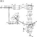
- FIG. 2 is a diagram illustrating an optical system in Embodiment 1.
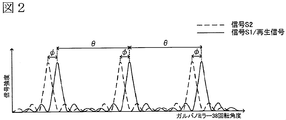
- FIG. It is a figure which shows the light quantity of the diffracted light with respect to the rotation angle of the galvanometer mirror 38 in Example 1.
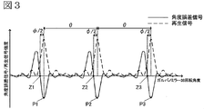
- FIG. It is a figure which shows the angle error signal 1 in Example 1.
- FIG. It is a figure which shows the flowchart regarding the angle control of the galvanometer mirror in Example 1.
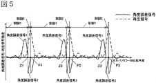
- FIG. It is a figure which shows the angle error signal in Example 1.
- FIG. 6 is a diagram illustrating another optical system in Embodiment 1.
- FIG. 6 is a diagram illustrating another optical system in Embodiment 1.
- FIG. FIG. 6 is a diagram illustrating an optical system in Example 2. It is a figure which shows the flowchart regarding the angle control of the galvanometer mirror in Example 2.
- FIG. FIG. FIG.
- FIG. 6 is a diagram illustrating an optical system in Example 3. It is a figure explaining the effect in Example 3.
- FIG. 6 is a diagram illustrating another optical system in Example 3.
- FIG. 6 is a diagram illustrating another optical system in Example 3.
- FIG. 10 is a diagram illustrating an optical system in Example 4.
- 1 is a diagram showing a hologram recording / reproducing apparatus in Example 1.
- FIG. 15 shows the overall configuration of the hologram recording / reproducing apparatus according to the first embodiment of the present invention.
- the hologram recording / reproducing apparatus includes, for example, an optical pickup device 60 configured as shown in FIG. 1, a phase conjugate optical system 512, an optical information recording medium Cure optical system 513, an optical information recording medium position detection optical system 514, and an optical information recording medium drive.
- the optical information recording medium 300 is provided with an element 70 so that the recording position relative to the optical pickup device can be changed.
- the optical pickup device 60 plays a role of emitting reference light and signal light to the optical information recording medium 300 and recording digital information using a hologram.
- the information signal to be recorded is sent by the controller 89 to the spatial light modulator in the optical pickup device 60 via the signal generation circuit 86, and the signal light is modulated by the spatial light modulator.
- the phase conjugate light of the reference light emitted from the optical pickup device 60 is generated by the phase conjugate optical system 512.
- the phase conjugate optical system 512 indicates, for example, the galvanometer mirror 50 in the case of FIG.
- the phase conjugate light is a light wave that travels in the opposite direction while maintaining the same wavefront as the input light.
- the reproduction light reproduced by the phase conjugate light is detected by the image pickup device in the optical pickup device 60, and the signal is reproduced by the signal processing circuit 85.
- the irradiation time of the reference light and the signal light applied to the optical information recording medium 300 can be adjusted by controlling a shutter opening / closing time described later in the optical pickup device 60 through the shutter control circuit 87 by the controller 89.
- the optical information recording medium Cure optical system 513 plays a role of generating a light beam used for pre-cure and post-cure of the optical information recording medium 300.
- the pre-cure is a pre-process in which, when information is recorded at a desired position in the optical information recording medium 300, a predetermined light beam is irradiated in advance before the reference light and signal light are irradiated to the desired position.
- Post-cure is a post-process for irradiating a predetermined light beam after recording information at a desired position in the optical information recording medium 300 so that additional recording cannot be performed at the desired position.
- the optical information recording medium position detection optical system 514 is used to detect the position of the optical information recording medium 300.
- a signal corresponding to the position is detected by the optical information recording medium position detection optical system 514, and the controller 89 uses the detected signal to pass the position control circuit 88.
- the position of the optical information recording medium 300 can be controlled.
- a predetermined light source driving current is supplied from the light source driving circuit 82 to the light sources in the optical pickup device 60, the optical information recording medium Cure optical system 513, and the optical information recording medium position detecting optical system 514. Can emit a light beam. Since the recording technique using holography is a technique capable of recording ultra-high-density information, for example, an allowable error with respect to the tilt of the optical information recording medium 300 tends to be extremely small. Therefore, a signal for detecting the angle error signal is output in the optical pickup device 60 of the present embodiment.
- the servo signal generation circuit 83 uses this signal to generate an angle error signal 1 and an angle error signal 2 for servo control, and controls an angle variable element such as a galvanometer mirror via the servo control circuit 84.
- the servo control circuit has a function of switching the angle error signal 1 and the angle error signal 2 and changing the control of an angle variable element such as a galvanometer mirror.
- optical pickup device 60 the phase conjugate optical system 512, the optical information recording medium Cure optical system 513, and the optical information recording medium position detection optical system 514 are combined with several optical system configurations or all optical system configurations. It may be simplified.
- FIG. 1 shows an optical system of an optical pickup device in a hologram recording / reproducing apparatus of a two-beam angle multiplexing system according to this embodiment.
- the reproduction method of this embodiment will be described with reference to FIG.
- the light beam emitted from the light source 11 passes through the collimator lens 12 and is converted into a desired beam diameter, and then enters the polarization variable element 14 through the shutter 13.
- the light beam is converted into S-polarized light by the polarization variable element 14.
- the polarization variable element 14 is an optical element that converts the light into predetermined polarized light according to recording or reproduction.
- the light beam that has passed through the polarization variable element 14 reflects the PBS prism 15.
- the light beam reflected from the PBS prism 15 is referred to as reference light.
- the reference light reflected by the PBS prism 15 is reflected by the mirror 36 and enters the wave plate 99.
- the wave plate 99 is an element that converts incident S-polarized light into a polarization component composed of P-polarized light and S-polarized light. Then, the reference light transmitted through the wave plate 99 enters the Wollaston prism 100.
- the Wollaston prism 100 is an optical element that branches into two beams whose propagation directions differ by an angle ⁇ according to the polarization of the incident light beam. For this reason, the light beam transmitted through the Wollaston prism 100 is a light beam in two propagation directions having different polarizations.
- the S-polarized light beam is referred to as reference light
- the P-polarized light beam is referred to as a control light beam.
- the two light beams that have passed through the Wollaston prism 100 are reflected by the mirror 37 and enter the angle correction element 101.
- the angle correction element 101 has a mechanism that allows the wedge prism to rotate, and is an element for correcting a substantially perpendicular angle with respect to the direction of angle multiplexing recording on the optical information recording medium 300.
- the light beam emitted from the angle correction element 101 is incident on the galvano mirror 38 (first angle variable element).
- the galvanometer mirror 38 is an optical element that can control the angle of the mirror. For this reason, by using the galvanometer mirror, the incident angle of the reference light to the optical information recording medium 300 can be changed, and angle multiplexing recording / reproduction can be realized. Further, the galvanometer mirror 38 is equipped with an optical system 538 for measuring a change in the angle of the mirror.
- the reference light reflected from the galvanometer mirror 38 enters the optical information recording medium 300 through the scanner lens 39.
- two diffracted lights corresponding to the incident angle are generated in the direction of the lens 701. These diffracted lights pass through the lens 701 and enter the PBS prism 702.
- the diffracted light generated in the optical information recording medium 300 is the same polarization as the incident polarized light
- the diffracted light generated from the reference light reflects the PBS prism 702
- the diffracted light generated from the control light beam is PBS.
- the light passes through the prism 702.
- each diffracted light is incident on the light receiving portion of the photodetector 704 and the photodetector 706 through the detection lens 703 and the detection lens 705.
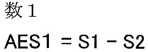
- the angle error signal 1 (AES1) can be expressed as follows.
- Signals S1 and S2 are sum signals obtained by detecting the total amount of each diffracted light.
- the reference light and the control light beam transmitted through the optical information recording medium 300 are transmitted through the quarter-wave plate 450 and are incident on the galvano mirror 50 (second angle variable element).
- the galvanometer mirror 50 is controlled based on angle information converted from the voltage value / current value input to the galvanometer mirror 38 so that the incident reference light is substantially perpendicular to the galvanometer mirror 50.
- the two light beams reflected from the galvanometer mirror 38 are transmitted through the quarter wavelength plate 450 again.
- the 1 ⁇ 4 wave plate 405 was transmitted before and after the reflection of the galvanometer mirror 38, the polarized light was converted, the reference light was P-polarized light, and the control light beam was S-polarized light.
- the two light beams transmitted through the quarter wavelength plate 450 are incident on the optical information recording medium 300. Then, the reference light and the control light beam generate reproduction light (diffracted light of the reference light) having predetermined information from the recording area and diffracted light of the control light beam in the direction of the objective lens 32.
- the PBS prism 28 transmits the reproduction light that is P-polarized light and reflects the diffracted light of the control light beam that is S-polarized light.
- the image sensor 51 detects the reproduction light transmitted through the PBS prism 28. Based on the reproduction light incident on the image sensor 51, reproduction image data is generated.
- the galvanometer mirror 38 is rotationally controlled using the angle error signal 1 and the angle error signal 2 obtained from the optical system 538, and the incident angle of the reference light to the optical information recording medium 300 is changed. Thereby, angle-multiplexed reproduction image data in the optical information recording medium 300 is generated.
- This embodiment is characterized in that the angle error signal 1 and the angle error signal 2 are switched, and the galvano mirror 38 is controlled by each signal.
- a method of detecting the angle error signal will be described.
- FIG. 2 shows the signal S1 obtained by the photodetector 704, the signal S2 obtained by the photodetector 706, and the signal strength of the reproduction signal when the galvanometer mirror 38 is rotated. Each signal intensity is normalized with the maximum value.
- the signal S1 and the signal S2 are shifted by an angle ⁇ with respect to the rotation angle of the galvanometer mirror 38. This is because the Wollaston prism 100 generates two light beams having different angles and detects them separately.
- FIG. 3 shows the angular differential signal 1 of the present invention calculated from the signals S1 and S2 of FIG. 3 that the angle Z1 (Z2, Z3) at which the angle error signal crosses zero is shifted from the angle P1 (P2, P3) at which the reproduction signal is maximum.
- the angle shift amount between P1 and Z1 (P2 and Z2, P3 and Z3) is approximately ⁇ / 2 because the angle difference between the signal S1 and the signal S2 shown in FIG. 2 is ⁇ .
- the angle error signal 2 is generated by the optical system 538 of FIG.
- the light beam emitted from the light source 138 is reflected by the prism 238, transmitted through the collimator lens 338, and converted into substantially parallel light.
- the substantially parallel light beam reflects from the mirror 38, passes through the collimating lens 338 and the prism 238, and forms a spot on the light receiving portion of the photodetector 438.
- the light receiving portion of the photodetector 438 is composed of a plurality of pixels and has a function of detecting the position of the incident spot.
- the angle error signal is generated so as to correct the amount of angle shift between P1 and Z1 (P2 and Z2, P3 and Z3) when controlled by the angle error signal 1.
- the angle error signal 2 (AES2) can be expressed as follows.
- X0 is the spot position on the photodetector 438 when the angle error signal 1 becomes Z1 (Z2, Z3), and Xi is on the photodetector 438 when the angle is shifted from X0 by about ⁇ / 2. It is the result (target position) which calculated the spot position.
- FIG. 4 shows a flowchart relating to the angle control of the galvanometer mirror 38 and the galvanometer mirror 50 when the same area on the optical information recording medium 300 is reproduced. Hereinafter, it demonstrates in order of a step.
- the galvanometer mirror 50 is driven by the angle information of the galvanometer mirror 38.
- the galvanometer mirror 50 is driven by the angle information of the galvanometer mirror 38.
- the galvanometer mirror 50 is driven by the angle method of the galvanometer mirror 38.
- FIG. 5 shows the signal intensity of the angle error signal and the reproduction signal with respect to the rotation angle when the galvano mirror 38 is driven in the flow of FIG.
- stable reproduction can be performed by controlling with the angle error signal 1 and switching to the angle error signal 2 at an angle at which the rotation angle is Z1.
- a photodetector that outputs only the light amount and the spot position can be driven at a high frequency, so that a signal can be detected at high speed. It becomes possible.
- the rotation angle of the galvanometer mirror can be controlled to the maximum amount of reproduction light, the best reproduction signal can be obtained.
- this method detects diffracted light, it is a method that resists disturbance during recording.
- the hologram recording / reproducing apparatus of the present embodiment selectively switches between the angle error signal using diffracted light and the two angle error signals of the angle variable element represented by the galvanometer mirror, and uses these signals. It is characterized by controlling an angle variable element represented by a galvanometer mirror. Further, the optical axis branching element typified by a Wollaston prism is characterized in that an angle error signal is generated by separating and detecting the reference light into two light beams having different propagation directions and polarizations.
- the galvanometer mirror 50 is controlled based on the angle information converted from the voltage value / current value input to the galvanometer mirror 38, but is not limited to this.
- a light beam reflected by the galvanometer mirror 50 and transmitted through the optical information recording medium 300 may be detected by the lens 102 and the photodetector 103 to generate an angle error signal for the galvanometer mirror 50.
- the angle error signal of the galvano mirror 50 can be generated by detecting the spot position.
- the galvanometer mirror 50 was the same control by the control 1 and the control 2, it is not limited to this.
- the galvanometer mirror 50 is controlled based on the angle information converted from the voltage value / current value input to the galvanometer mirror 38 and the angle information obtained from the optical system 538 in the control 1, and in the control 2,
- the final control angle (Z1) of control 1 may be fixed. By doing so, one element (galvano mirror 38) is driven for a certain period of time, so that there is an advantage that the speed can be further increased.
- the galvano mirror 50 is controlled so that the directions of the incident light beam and the reflected light beam are reversed, for example, as shown in FIG. 7, a configuration using a lens 52 fixed mirror 150 may be used. With such a configuration, the number of drive components (galvano mirror 50) can be reduced, and there is an advantage that the speed can be further increased.
- the amount of angular deviation between P1 and Z1 has been described as approximately ⁇ / 2, but may vary depending on the light amount and the signal amplification factor.
- the angle error signal 2 may be used for driving based on learning by the hologram apparatus or a pre-calculated result.
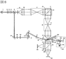
- FIG. 8 shows an optical system of an optical pickup device in a hologram recording / reproducing apparatus of a two-beam angle multiplexing system according to the second embodiment of the present invention.
- the difference from the first embodiment is that an optical system 538 for generating the angle error signal 2 is mounted on the galvanometer mirror 50.
- the second embodiment is the same as the first embodiment, and in this embodiment, a method for controlling the angles of the galvanometer mirror 38 and the galvanometer mirror 50 different from the first embodiment will be described.
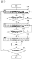
- FIG. 9 shows a flowchart relating to the angle control of the galvanometer mirror 38 and the galvanometer mirror 50 when reproducing the same area on the optical information recording medium 300.
- S1A The galvanometer mirror 38 is driven using the angle error signal 1.
- the galvanometer mirror 50 is driven based on the angle information of the galvanometer mirror 38.
- S2A It is confirmed that the angle error signal 1 is zero-crossed.
- S3A The galvanometer mirror 38 is controlled so that the angle error signal 1 zero-crosses.
- the galvanometer mirror 50 is driven using the angle error signal 2.
- S4A It is confirmed that the angle error signal 2 crosses zero.
- S5A The galvanometer mirror 38 is controlled so that the angle error signal 1 zero-crosses.
- the galvanometer mirror 50 is controlled so that the angle error signal 2 crosses zero.
- S6A An image is detected and reproduced.
- S7A Confirmation of next image Stable reproduction can be performed even when the angle error signal for controlling the galvano mirror 50 is switched as described above in the first embodiment.
- the hologram recording / reproducing apparatus of the present embodiment selectively switches between the angle error signal using diffracted light and the two angle error signals of the angle variable element represented by the galvanometer mirror, and uses these signals. It is characterized by controlling an angle variable element represented by a galvanometer mirror. Further, the optical axis branching element typified by a Wollaston prism is characterized in that an angle error signal is generated by separating and detecting the reference light into two light beams having different propagation directions and polarizations.
- the galvanometer mirror 38 is controlled at the time of the control 2, but it may be fixed. By doing so, one element (galvanometer mirror 50) is driven for a certain period of time, so that there is an advantage that the speed can be further increased.
- FIG. 10 shows an optical system of an optical pickup device in a hologram recording / reproducing apparatus of a two-beam angle multiplexing system according to the third embodiment of the present invention.
- the angle error signal is detected by detecting the light beam incident on the optical information recording medium 300 after being reflected by the galvanometer mirror 38.
- the present embodiment is characterized in that the angle error signal is detected by detecting the light beam reflected on the galvano mirror 50 and incident on the optical information recording medium 300.
- the reference light reflected from the galvanometer mirror 38 enters the galvanometer mirror 50 (second angle variable element) through the scanner lens 39, the optical information recording medium 300, and the quarter wavelength plate 450.
- the galvanometer mirror 50 is based on angle information converted from the voltage value / current value input to the galvanometer mirror 38 and angle information obtained from the optical system 538 so that the incident reference light is substantially perpendicular to the galvanometer mirror 50. Is controlled. Then, the two incident light beams are transmitted through the quarter-wave plate 450 again.
- the 1 ⁇ 4 wave plate 405 was transmitted before and after the reflection of the galvanometer mirror 38, the polarized light was converted, the reference light was P-polarized light, and the control light beam was S-polarized light.
- the two light beams transmitted through the quarter wavelength plate 450 are incident on the optical information recording medium 300. Then, the reference light and the control light beam generate reproduction light (diffracted light of the reference light) having predetermined information from the recording area and diffracted light of the control light beam in the direction of the objective lens 32.
- the prism 401 has polarization characteristics.
- the P-polarized light has a transmittance of 90% and a reflectance of 10%
- the S-polarized light has a transmittance of 0% and a reflectance of 100%.
- the diffracted light generated in the optical information recording medium 300 is the same polarization as the incident polarized light
- the reproduction light generated from the reference light is transmitted through the prism 401 by 90% and reflected by 10%.
- the diffracted light generated from the control light beam reflects 100% of the prism 401.
- the two light beams reflected by the prism 401 enter the PBS prism 402.
- the reproduction light is transmitted through the PBS prism, and the diffracted light generated from the control light beam is reflected from the PBS prism.
- Each diffracted light is incident on the light receiving portions of the light detector 404 and the light detector 406 through the detection lens 403 and the detection lens 405.
- the angle error signal 1 (AES1) can be expressed as follows.
- Signals S1 and S2 are sum signals obtained by detecting the total amount of each diffracted light.
- the reproduction light transmitted through the PBS prism 401 enters the image sensor 51 through the relay lens 30, the spatial filter 31, and the PBS prism 28. Based on the reproduction light incident on the image sensor 51, reproduction image data is generated.
- the galvanometer mirror 38 is rotationally controlled using the angle error signal 1 and the angle error signal 2 obtained from the optical system 538, and the incident angle of the reference light to the optical information recording medium 300 is changed. Thereby, angle-multiplexed reproduction image data in the optical information recording medium 300 is generated.
- the difference between the present embodiment and the first embodiment is the difference in the arrangement of the optical system for detecting the angle error signal 1, and the detection method of the angle error signal is the same. Therefore, the detection is performed for the same reason as in the first embodiment. Is possible.
- the flowchart regarding the angle control of the galvanometer mirror 38 and the galvanometer mirror 50 is the same as that of the first embodiment.
- This embodiment has an advantage that high resistance to disturbance can be obtained by arranging it in the same direction as the reproduction light. The reason will be described below.
- the angle correction element 101 is arranged in the first embodiment and the present embodiment.
- the angle correction element 101 has an advantage that it can be controlled at a high speed and with a higher accuracy than the attitude of the optical information recording medium.
- the problem is that the signal performance deteriorates when the correction amount of the angle correction element 101 increases.
- FIG. 11 shows a vertical view of FIG. 1 (or FIG. 8).
- the light beam 55 and the light beam 60 indicate the propagation direction of the light beam
- the diffracted light 55D and the diffracted light 60D schematically show the diffracted light when the light beam 55 and the light beam 60 are incident.
- Yes. (A) shows the case where the optical information recording medium 300 is not tilted
- (b) and (c) show the case where the optical information recording medium 300 is tilted in the vertical direction with respect to the direction in which the recording is multiplexed. Show. Note that (b) and (c) differ in the inclination of the light beam with respect to the optical information recording medium 300 before and after the incidence of the galvanometer mirror 50.
- the angle error signal 1 of the first embodiment can obtain a certain level of performance by being electrically amplified. However, when the angle error signal 1 is detected in the same direction as the reproduction light as in this embodiment, a more stable angle error signal is obtained. There is an advantage that can be obtained.
- the tilt of the optical information recording medium 300 may be changed, but it is advantageous to drive the angle correction element from the viewpoint of speed.
- Non-Patent Document 1 As shown in Non-Patent Document 1 (INTERNATIONAL, SYMPOSIUM, OPTICAL, MEMORY2012, Mo-C-01) is used, the wavefront with respect to the optical information recording medium 300 before and after the incidence of the galvanometer mirror 50 is used. Therefore, the configuration of the present embodiment is more advantageous than the first embodiment.
- the hologram recording / reproducing apparatus of the present embodiment selectively switches between the angle error signal using diffracted light and the two angle error signals of the angle variable element represented by the galvanometer mirror, and uses these signals. It is characterized by controlling an angle variable element represented by a galvanometer mirror. Further, the optical axis branching element typified by a Wollaston prism is characterized in that an angle error signal is generated by separating and detecting the reference light into two light beams having different propagation directions and polarizations. Further, the present embodiment is characterized in that the angle error signal 1 is generated using the diffracted light generated in the same direction as the reproduction light, so that more stable control can be performed.
- the galvanometer mirror 50 is controlled based on the angle information converted from the voltage value / current value input to the galvanometer mirror 38, but is not limited to this.
- an angle error signal for the galvano mirror 50 may be generated by detecting the light beam reflected by the galvano mirror 50 and transmitted through the optical information recording medium 300 with the lens 102 and the photodetector 103 as shown in FIG. . Since the angular deviation of the light beam becomes a spot deviation on the photodetector 103, an angular error signal can be generated by detecting the position.
- the galvanometer mirror 50 was the same control by the control 1 and the control 2, it is not limited to this.
- the galvanometer mirror 50 is controlled based on angle information converted from the voltage value / current value input to the galvanometer mirror 38 at the time of control 1, and the final control angle (Z1) of control 1 at the time of control 2. It may be fixed with. By doing so, one drive element (galvano mirror 38) is provided for a certain period of time, and thus there is an advantage that the speed can be further increased.
- the galvanometer mirror 50 of this embodiment is controlled so that the directions of the incident light beam and the reflected light beam are reversed. For example, as shown in FIG. May be. With such a configuration, the number of drive components (galvano mirror 50) can be reduced, and there is an advantage that the speed can be further increased.
- FIG. 14 shows an optical system of an optical pickup device in a hologram recording / reproducing apparatus of a two-beam angle multiplexing system according to the fourth embodiment of the present invention.
- the difference from the third embodiment is that an optical system 538 for generating the angle error signal 2 is mounted on the galvanometer mirror 50. Since the rest is the same as in the first embodiment, in this embodiment, a method for controlling the angles of the galvanometer mirror 38 and the galvanometer mirror 50 different from the third embodiment will be described.
- FIG. 9 shows a flowchart relating to the angle control of the galvanometer mirror 38 and the galvanometer mirror 50 when reproducing the same area on the optical information recording medium 300.
- S1A The galvanometer mirror 38 is driven using the angle error signal 1.
- the galvanometer mirror 50 is driven by the angle method of the galvanometer mirror 38.
- S2A It is confirmed that the angle error signal 1 is zero-crossed.
- S3A The galvanometer mirror 38 is controlled so that the angle error signal 1 zero-crosses.
- the galvanometer mirror 50 is driven using the angle error signal 2.
- S4A It is confirmed that the angle error signal 2 crosses zero.
- S5A The galvanometer mirror 38 is controlled so that the angle error signal 1 zero-crosses.
- the galvanometer mirror 50 is controlled so that the angle error signal 2 crosses zero.
- S6A An image is detected and reproduced.
- S7A Confirmation of next image Stable reproduction can be performed even when the angle error signal for controlling the galvano mirror 50 is switched as described above in the first embodiment.
- the hologram recording / reproducing apparatus of the present embodiment selectively switches between the angle error signal using diffracted light and the two angle error signals of the angle variable element represented by the galvanometer mirror, and uses these signals. It is characterized by controlling an angle variable element represented by a galvanometer mirror. Further, the optical axis branching element typified by a Wollaston prism is characterized in that an angle error signal is generated by separating and detecting the reference light into two light beams having different propagation directions and polarizations. Further, the present embodiment is characterized in that the angle error signal 1 is generated using the diffracted light generated in the same direction as the reproduction light, so that more stable control can be performed.
- the galvanometer mirror 38 is controlled at the time of the control 2, but it may be fixed. By doing so, one element (galvanometer mirror 50) is driven for a certain period of time, so that there is an advantage that the speed can be further increased.
- the optical system 538 for measuring the change in the angle of the mirror of the galvanometer mirror is arranged.
- this embodiment is characterized in that the two angular error signals are switched and controlled.
- the method for detecting the angle of the mirror is not limited.
- the angle error signal 2 may be output from a rotary encoder inside the galvanometer mirror as described in Patent Document 2 (WO 99/54688).
- the control of the galvanometer mirror 38 and the galvanometer mirror 50 has been described.
- the present invention is not limited to this, and the angle error signal of at least one of the plurality of angle variable elements is switched. It may be configured to be controlled.
- the propagation direction of the light beam is changed using a galvanometer mirror.
- an angle variable element such as an acousto-optic element may be used.
- the wedge prism is used to correct the angle substantially perpendicular to the direction of angle-multiplexed recording on the optical information recording medium 300.
- an angle correction element such as a galvanometer mirror is used. It may be.
- the switching between the control 1 and the control 2 is performed at an angle at which the angle error signal 1 is zero-crossed.
- the angle error signal 2 may be used for driving according to the above learning or a pre-calculated result.
- the angle-multiplexed hologram has been described. However, the same effect can be obtained from another system in terms of switching control signals.
- this invention is not limited to the above-mentioned Example, Various modifications are included.
- the above-described embodiments have been described in detail for easy understanding of the present invention, and are not necessarily limited to those having all the configurations described.
- a part of the configuration of one embodiment can be replaced with the configuration of another embodiment, and the configuration of another embodiment can be added to the configuration of one embodiment.
Landscapes
- Physics & Mathematics (AREA)
- Optics & Photonics (AREA)
- General Physics & Mathematics (AREA)
- Engineering & Computer Science (AREA)
- Signal Processing (AREA)
- Optical Head (AREA)
- Optical Recording Or Reproduction (AREA)
- Holo Graphy (AREA)
Abstract
Description
さらに、特許文献1の場合には、予め決められた角度分だけ参照光の角度をずらす制御方法であるため、記録時の外乱等の影響により制御精度が低下し、再生性能が劣化してしまう課題がある。
そこで、本発明では、2光束角度多重方式において高速再生を実現可能でかつ、より良い再生信号を得られる角度誤差信号を検出可能なホログラム記録再生装置、角度多重記録再生方式を提供することを目的とする。
ホログラフィを利用した記録技術は、超高密度な情報を記録可能な技術であるがゆえに、例えば光情報記録媒体300の傾きに対する許容誤差が極めて小さくなる傾向がある。それゆえ本実施例の光ピックアップ装置60内には角度誤差信号を検出するための信号が出力される。この信号を用いて、サーボ信号生成回路83にてサーボ制御用の角度誤差信号1および角度誤差信号2を生成し、サーボ制御回路84を介してガルバノミラー等の角度可変素子を制御する。また、サーボ制御回路は、角度誤差信号1と角度誤差信号2を切替え、ガルバノミラー等の角度可変素子の制御を変える機能を有している。


(S1A)角度誤差信号1を用いてガルバノミラー38を駆動する。
(S2A)角度誤差信号1がゼロクロスすることを確認する。
(S3A)角度誤差信号1がゼロクロスするようガルバノミラー38を制御する。
(S4A)角度誤差信号2がゼロクロスすることを確認する。
(S5A)角度誤差信号1がゼロクロスするようガルバノミラー38を制御する。
(S6A)画像を検出し、再生する。
(S7A)次の画像があるか確認
実施例1に対し、上記のようにガルバノミラー50を制御する角度誤差信号を切替えても安定した再生を行うことが可能となる。
(S1A)角度誤差信号1を用いてガルバノミラー38を駆動する。
(S2A)角度誤差信号1がゼロクロスすることを確認する。
(S3A)角度誤差信号1がゼロクロスするようガルバノミラー38を制御する。
(S4A)角度誤差信号2がゼロクロスすることを確認する。
(S5A)角度誤差信号1がゼロクロスするようガルバノミラー38を制御する。
(S6A)画像を検出し、再生する。
(S7A)次の画像があるか確認
実施例1に対し、上記のようにガルバノミラー50を制御する角度誤差信号を切替えても安定した再生を行うことが可能となる。
Claims (10)
- 光情報記録媒体に信号光と参照光を照射してホログラムを形成することで情報信号を記録し、光情報記録媒体内のホログラムに参照光を照射することで情報信号を再生するホログラム記録再生装置であって、
光ビームを出射する光源と、
光源から出射した光ビームを信号光と参照光に分岐する分岐部と、
光情報記録媒体に入射する参照光の入射角度を変えるための角度調整部と、
信号光に情報を付加するための空間光変調部と、
光情報記録媒体に信号光を照射するための対物レンズと、
前記参照光を光情報記録媒体に照射したときに光情報記録媒体内のホログラムから発生する回折光を検出するための撮像部と、
角度可変部を制御するための第一、第二の少なくとも2つの角度誤差信号を検出するための検出部と、
を備え、
前記第一、第二の角度誤差信号を切替えて、前記角度調整部を制御することを特徴とするホログラム記録再生装置。 - 請求項1記載のホログラム記録再生装置であって、
撮像部とは異なる回折光を検出するための光検出部と、
前記角度調整部の角度を測定するための角度検出部と、
を備え、
前記光検出部で検出した回折光から前記角度調整部の第一の角度誤差信号を生成し、
前記角度検出部の信号から第二の角度誤差信号を生成し、
前記第一、第二の角度誤差信号を切替えて、前記角度調整部を制御することを特徴とするホログラム記録再生装置。 - 請求項2記載のホログラム記録再生装置であって、
前記参照光を分岐する光軸分岐部と、
を備え、
前記光軸分岐部を透過した参照光は伝搬方向の異なる第一、第二の少なくとも2つの光ビームに分岐され、
光情報記録媒体に前記第一、第二の光ビームが入射したときに光情報記録媒体内の記録領域から発生する第一、第二の回折光を前記光検出部で検出して第一の角度誤差信号を生成し、
前記角度調整部の角度を前記角度検出部で検出して第二の角度誤差信号を生成し、
前記第一、第二の角度誤差信号を切替えて、前記角度調整部を制御することを特徴とするホログラム記憶再生装置。 - 請求項3記載のホログラム記録再生装置において、
前記第一、第二の光ビームは、偏光が直交していることを特徴とするホログラム記録再生装置。 - 請求項4記載のホログラム記録再生装置において、
前記第一、第二の光ビームの伝播方向が角度φだけ異なるとき、
第一の角度誤差信号と第二の角度誤差信号のゼロクロス角度の違いは略φ/2であることを特徴とするホログラム記録再生装置。 - 請求項5記載のホログラム記録再生装置において、
第一の角度誤差信号が所定の値になった時点で第一の角度誤差信号から第二の角度誤差信号に切替えることを特徴とするホログラム記憶再生装置。 - 請求項5記載のホログラム記録再生装置において、
前記第一、第二の角度誤差信号の切替えは
第一の角度誤差信号が0になった時点で第一の角度誤差信号から第二の角度誤差信号に切替えることを特徴とするホログラム記憶再生装置。 - 請求項7記載のホログラム記録再生装置において、
前記第一、第二の角度誤差信号の切替えは
第二の角度誤差信号が所定の値になった時点で第二の角度誤差信号から第一の角度誤差信号に切替えることを特徴とするホログラム記憶再生装置。 - 請求項8記載のホログラム記録再生装置において、
前記第一、第二の角度誤差信号の切替えは
所定参照光角度で再生が終了した時点で第二の角度誤差信号から第一の角度誤差信号に切替えることを特徴とするホログラム記憶再生装置。 - 信号光と参照光を用いた角度多重記録再生方式において、
第一、 第二の角度誤差を計測するステップと、
測定された第一、第二の角度誤差を切り替えて、光情報記録媒体への参照光入射角度を制御するステップと、
を有し、
前記第一の角度誤差は、光情報記録媒体に第一の方向から参照光を入射したときに発生する第一の回折光と、第一の方向とは異なる方向から参照光を入射したときに発生する第二の回折光から計測され、
前記第二の角度誤差は、参照光角度の変化量から計測され、
ることを特徴とする角度多重記録再生方式。
Priority Applications (4)
| Application Number | Priority Date | Filing Date | Title |
|---|---|---|---|
| PCT/JP2013/060424 WO2014162582A1 (ja) | 2013-04-05 | 2013-04-05 | ホログラム記録再生装置、角度多重記録再生方式 |
| JP2015509830A JP6158311B2 (ja) | 2013-04-05 | 2013-04-05 | ホログラム記録再生装置、角度多重記録再生方式 |
| US14/781,595 US9508377B2 (en) | 2013-04-05 | 2013-04-05 | Hologram recording and reproducing device, and angular multiplexing recording and reproducing method |
| CN201380075330.0A CN105074583B (zh) | 2013-04-05 | 2013-04-05 | 全息记录再现装置和角度复用记录再现方式 |
Applications Claiming Priority (1)
| Application Number | Priority Date | Filing Date | Title |
|---|---|---|---|
| PCT/JP2013/060424 WO2014162582A1 (ja) | 2013-04-05 | 2013-04-05 | ホログラム記録再生装置、角度多重記録再生方式 |
Publications (1)
| Publication Number | Publication Date |
|---|---|
| WO2014162582A1 true WO2014162582A1 (ja) | 2014-10-09 |
Family
ID=51657910
Family Applications (1)
| Application Number | Title | Priority Date | Filing Date |
|---|---|---|---|
| PCT/JP2013/060424 Ceased WO2014162582A1 (ja) | 2013-04-05 | 2013-04-05 | ホログラム記録再生装置、角度多重記録再生方式 |
Country Status (4)
| Country | Link |
|---|---|
| US (1) | US9508377B2 (ja) |
| JP (1) | JP6158311B2 (ja) |
| CN (1) | CN105074583B (ja) |
| WO (1) | WO2014162582A1 (ja) |
Families Citing this family (2)
| Publication number | Priority date | Publication date | Assignee | Title |
|---|---|---|---|---|
| US11243450B2 (en) * | 2017-01-30 | 2022-02-08 | The Charles Stark Draper Laboratory, Inc. | Saw modulator having optical power component for extended angular redirection of light |
| US10935868B2 (en) * | 2017-09-28 | 2021-03-02 | The Charles Stark Draper Laboratory, Inc. | System and method for diffractive steering of electromagnetic radiation |
Citations (2)
| Publication number | Priority date | Publication date | Assignee | Title |
|---|---|---|---|---|
| JP2008287077A (ja) * | 2007-05-18 | 2008-11-27 | Canon Inc | 光情報記録再生装置 |
| JP2012154979A (ja) * | 2011-01-24 | 2012-08-16 | Hitachi Consumer Electronics Co Ltd | 光情報再生方法および光情報再生装置 |
Family Cites Families (6)
| Publication number | Priority date | Publication date | Assignee | Title |
|---|---|---|---|---|
| JP2009087448A (ja) * | 2007-09-28 | 2009-04-23 | Hitachi Ltd | ホログラム記録再生装置及びホログラム記録再生方法 |
| US8446808B2 (en) * | 2008-02-14 | 2013-05-21 | Akonia Holographics, Llc | Use of feedback error and/or feed-forward signals to adjust control axes to optimal recovery position of hologram in holographic data storage system or device |
| JP5178411B2 (ja) * | 2008-09-04 | 2013-04-10 | 株式会社東芝 | 光情報記録再生装置 |
| JP5274959B2 (ja) * | 2008-09-25 | 2013-08-28 | 株式会社東芝 | 光情報記録装置および方法 |
| JP2011187101A (ja) * | 2010-03-05 | 2011-09-22 | Hitachi Consumer Electronics Co Ltd | 光情報記録再生装置、及び光情報再生方法 |
| JP5726816B2 (ja) * | 2012-06-19 | 2015-06-03 | 日立コンシューマエレクトロニクス株式会社 | ホログラム用光ピックアップ装置、光情報記録再生装置、光情報記録再生方法、及び光情報装置 |
-
2013
- 2013-04-05 WO PCT/JP2013/060424 patent/WO2014162582A1/ja not_active Ceased
- 2013-04-05 JP JP2015509830A patent/JP6158311B2/ja not_active Expired - Fee Related
- 2013-04-05 CN CN201380075330.0A patent/CN105074583B/zh not_active Expired - Fee Related
- 2013-04-05 US US14/781,595 patent/US9508377B2/en not_active Expired - Fee Related
Patent Citations (2)
| Publication number | Priority date | Publication date | Assignee | Title |
|---|---|---|---|---|
| JP2008287077A (ja) * | 2007-05-18 | 2008-11-27 | Canon Inc | 光情報記録再生装置 |
| JP2012154979A (ja) * | 2011-01-24 | 2012-08-16 | Hitachi Consumer Electronics Co Ltd | 光情報再生方法および光情報再生装置 |
Also Published As
| Publication number | Publication date |
|---|---|
| US20160055875A1 (en) | 2016-02-25 |
| JP6158311B2 (ja) | 2017-07-05 |
| JPWO2014162582A1 (ja) | 2017-02-16 |
| CN105074583B (zh) | 2018-02-16 |
| CN105074583A (zh) | 2015-11-18 |
| US9508377B2 (en) | 2016-11-29 |
Similar Documents
| Publication | Publication Date | Title |
|---|---|---|
| US10037775B2 (en) | Optical information device and optical information processing method | |
| US20120188618A1 (en) | Optical information reproducing method and optical information reproducing apparatus | |
| CN103514908B (zh) | 光信息记录再现装置和光信息记录再现方法 | |
| JP5753768B2 (ja) | 光情報記録装置、光情報再生装置、光情報記録再生装置、光情報記録方法、光情報再生方法および光情報記録再生方法 | |
| US7990830B2 (en) | Optical pickup, optical information recording apparatus and optical information recording and reproducing apparatus using the optical pickup | |
| JP2014026706A (ja) | ホログラフィックメモリ装置および参照光入射角度調整方法 | |
| JP6158311B2 (ja) | ホログラム記録再生装置、角度多重記録再生方式 | |
| US8830809B2 (en) | Optical information recording device | |
| US9081364B2 (en) | Optical information recording/reproducing apparatus, optical information recording/reproducing method, and optical information recording medium | |
| JP2007141426A (ja) | ホログラフィックメモリ装置 | |
| CN105359212A (zh) | 光信息记录再现装置和调节方法 | |
| JP5816132B2 (ja) | ホログラム用光ピックアップ装置及び光情報記録再生装置 | |
| US9443548B2 (en) | Hologram reproducing device and hologram reproducing method | |
| JP6077110B2 (ja) | 光情報再生装置および調整方法 | |
| US20100195179A1 (en) | Hologram reproducing device and hologram reproducing method | |
| US9087522B2 (en) | Optical information reproducing device and reference beam adjusting method | |
| US9601147B2 (en) | Optical information recording and reproducing apparatus and optical information recording and reproducing method | |
| WO2011108105A1 (ja) | ホログラム再生方法 | |
| US20170236543A1 (en) | Optical information recording/reproducing device and holographic recording/reproducing method | |
| US9190097B2 (en) | Optical information recording/reproducing device and optical information recording/reproducing method | |
| JP2017126390A (ja) | 光情報記録装置、及び光情報記録方法 | |
| WO2014073041A1 (ja) | ホログラム光ピックアップ装置、ホログラム装置、高速撮像装置 | |
| WO2016163312A1 (ja) | 光情報再生装置及び光情報再生方法 | |
| WO2015083245A1 (ja) | 記録再生装置、及び記録再生方法 |
Legal Events
| Date | Code | Title | Description |
|---|---|---|---|
| WWE | Wipo information: entry into national phase |
Ref document number: 201380075330.0 Country of ref document: CN |
|
| 121 | Ep: the epo has been informed by wipo that ep was designated in this application |
Ref document number: 13881004 Country of ref document: EP Kind code of ref document: A1 |
|
| WWE | Wipo information: entry into national phase |
Ref document number: 14781595 Country of ref document: US |
|
| ENP | Entry into the national phase |
Ref document number: 2015509830 Country of ref document: JP Kind code of ref document: A |
|
| NENP | Non-entry into the national phase |
Ref country code: DE |
|
| 122 | Ep: pct application non-entry in european phase |
Ref document number: 13881004 Country of ref document: EP Kind code of ref document: A1 |