WO2014155945A1 - Engine and portable working machine - Google Patents
Engine and portable working machine Download PDFInfo
- Publication number
- WO2014155945A1 WO2014155945A1 PCT/JP2014/000835 JP2014000835W WO2014155945A1 WO 2014155945 A1 WO2014155945 A1 WO 2014155945A1 JP 2014000835 W JP2014000835 W JP 2014000835W WO 2014155945 A1 WO2014155945 A1 WO 2014155945A1
- Authority
- WO
- WIPO (PCT)
- Prior art keywords
- exhaust
- engine
- passage
- opening
- cylinder
- Prior art date
- Legal status (The legal status is an assumption and is not a legal conclusion. Google has not performed a legal analysis and makes no representation as to the accuracy of the status listed.)
- Ceased
Links
Images







Classifications
-
- F—MECHANICAL ENGINEERING; LIGHTING; HEATING; WEAPONS; BLASTING
- F01—MACHINES OR ENGINES IN GENERAL; ENGINE PLANTS IN GENERAL; STEAM ENGINES
- F01N—GAS-FLOW SILENCERS OR EXHAUST APPARATUS FOR MACHINES OR ENGINES IN GENERAL; GAS-FLOW SILENCERS OR EXHAUST APPARATUS FOR INTERNAL-COMBUSTION ENGINES
- F01N13/00—Exhaust or silencing apparatus characterised by constructional features
- F01N13/002—Apparatus adapted for particular uses, e.g. for portable devices driven by machines or engines
-
- F—MECHANICAL ENGINEERING; LIGHTING; HEATING; WEAPONS; BLASTING
- F02—COMBUSTION ENGINES; HOT-GAS OR COMBUSTION-PRODUCT ENGINE PLANTS
- F02B—INTERNAL-COMBUSTION PISTON ENGINES; COMBUSTION ENGINES IN GENERAL
- F02B63/00—Adaptations of engines for driving pumps, hand-held tools or electric generators; Portable combinations of engines with engine-driven devices
- F02B63/02—Adaptations of engines for driving pumps, hand-held tools or electric generators; Portable combinations of engines with engine-driven devices for hand-held tools
-
- F—MECHANICAL ENGINEERING; LIGHTING; HEATING; WEAPONS; BLASTING
- F01—MACHINES OR ENGINES IN GENERAL; ENGINE PLANTS IN GENERAL; STEAM ENGINES
- F01N—GAS-FLOW SILENCERS OR EXHAUST APPARATUS FOR MACHINES OR ENGINES IN GENERAL; GAS-FLOW SILENCERS OR EXHAUST APPARATUS FOR INTERNAL-COMBUSTION ENGINES
- F01N2340/00—Dimensional characteristics of the exhaust system, e.g. length, diameter or volume of the exhaust apparatus; Spatial arrangements of exhaust apparatuses
-
- F—MECHANICAL ENGINEERING; LIGHTING; HEATING; WEAPONS; BLASTING
- F01—MACHINES OR ENGINES IN GENERAL; ENGINE PLANTS IN GENERAL; STEAM ENGINES
- F01N—GAS-FLOW SILENCERS OR EXHAUST APPARATUS FOR MACHINES OR ENGINES IN GENERAL; GAS-FLOW SILENCERS OR EXHAUST APPARATUS FOR INTERNAL-COMBUSTION ENGINES
- F01N2470/00—Structure or shape of exhaust gas passages, pipes or tubes
- F01N2470/30—Tubes with restrictions, i.e. venturi or the like, e.g. for sucking air or measuring mass flow
-
- F—MECHANICAL ENGINEERING; LIGHTING; HEATING; WEAPONS; BLASTING
- F01—MACHINES OR ENGINES IN GENERAL; ENGINE PLANTS IN GENERAL; STEAM ENGINES
- F01N—GAS-FLOW SILENCERS OR EXHAUST APPARATUS FOR MACHINES OR ENGINES IN GENERAL; GAS-FLOW SILENCERS OR EXHAUST APPARATUS FOR INTERNAL-COMBUSTION ENGINES
- F01N2590/00—Exhaust or silencing apparatus adapted to particular use, e.g. for military applications, airplanes, submarines
- F01N2590/06—Exhaust or silencing apparatus adapted to particular use, e.g. for military applications, airplanes, submarines for hand-held tools or portables devices
-
- F—MECHANICAL ENGINEERING; LIGHTING; HEATING; WEAPONS; BLASTING
- F02—COMBUSTION ENGINES; HOT-GAS OR COMBUSTION-PRODUCT ENGINE PLANTS
- F02B—INTERNAL-COMBUSTION PISTON ENGINES; COMBUSTION ENGINES IN GENERAL
- F02B25/00—Engines characterised by using fresh charge for scavenging cylinders
Definitions
- the present invention relates to an engine used as a power source in a portable working machine such as a chainsaw and a cutter, and to a portable working machine equipped with the engine.
- an engine serving as a power source is required to have high power, to be downsized, and to be light, and therefore, usage of a two-stroke one-cycle engine as the power source is mainstream.
- the two-stroke one-cycle engine unburned gas is discharged from an exhaust port of a combustion chamber during the exhaust and scavenging processes in the engine, and the exhaust gas property is deteriorated. Accordingly, in order to suppress the deterioration of the exhaust gas property in the two-stroke one-cycle engine, a catalytic method, an air-lead scavenging method, an exhaust-pulse method, etc., are adopted.
- a catalyst is arranged in a discharge passage of the exhaust gas for purifying the exhaust gas.
- the air-lead scavenging method is a method of leading air in a scavenging passage to the combustion chamber during the exhaust and scavenging processes of the engine before the unburned gas is discharged from the combustion chamber.
- the exhaust-pulse scavenging method is a method of causing the unburned gas to remain in the combustion chamber by propagating a pressure wave of a combustion gas, that is discharged from the exhaust port, to the exhaust port at a later stage of the exhaust process of the engine.
- the patent literature 1 describes an example of an engine having a structure which suppresses the deterioration of the exhaust gas property by the exhaust-pulse scavenging method of the above-described methods and an example of a portable working machine equipped with the engine.
- This engine described in the patent literature 1 has an exhaust pipe provided on downstream of the exhaust port and a branch pipe branched from the exhaust pipe. A downstream end of the exhaust pipe is connected to outside of a muffler via an expansion chamber.
- the exhaust gas is discharged from the combustion chamber to the exhaust pipe, pressure inside the expansion chamber is propagated through the exhaust pipe to the vicinity of the exhaust port right before the end of the exhaust process, and the pressure reflected inside the branch pipe is propagated through the exhaust pipe to the vicinity of the exhaust port.
- the pressure in the vicinity of the exhaust port right before the end of the exhaust process is lifted up, and the unburned gas remains inside the combustion chamber, so that the deterioration of the exhaust gas property can be suppressed, and the engine power can be improved.
- a preferred aim of the present invention is to provide an engine that further improves a function of causing the unburned gas to remain in the combustion chamber and provide a portable working machine equipped with the engine.
- An engine is an engine having a combustion chamber provided inside a cylinder, in which an exhaust port connected to the combustion chamber is opened and closed by a piston reciprocating inside the cylinder.
- the engine includes: a first exhaust passage provided in the cylinder and connected to the exhaust port; an opening formed on a downstream end of the first exhaust passage in a direction of discharge of the combustion gas discharged from the exhaust port; and a second exhaust passage connected to the opening via a connection passage, and center of the connection passage in a cylinder axial direction and center of the opening in the cylinder axial direction are arranged at different positions from each other in the cylinder axial direction.
- a portable working machine is a portable working machine including: an engine in which a combustion chamber is provided inside a cylinder and an exhaust port connected to the combustion chamber is opened and closed by a piston reciprocating inside the cylinder, and an operating member that is operated by power transmitted from the engine to the operating member.
- the engine includes: a first exhaust passage provided in the cylinder and connected to the exhaust port; an opening formed on a downstream end of the first exhaust passage in a direction of discharge of the combustion gas discharged from the exhaust port; and a second exhaust passage connected to the opening via a connection passage, and a center of the connection passage in a cylinder axial direction and a center of the opening in the cylinder axial direction are arranged at different positions from each other in the cylinder axial direction.
- pressure wave to be propagated from the second exhaust passage through the connection passage to the exhaust port is easily propagated to the exhaust port, so that decrease in the function of causing the unburned gas to remain in the combustion chamber can be suppressed.
- FIG. 1 is a front cross-sectional view illustrating a portable working machine having an engine of the present invention
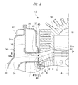
- FIG. 2 is an enlarged cross-sectional view illustrating a structural example of the engine of the present invention
- FIG. 3 is an outline view of the engine illustrated in FIG. 1
- FIG. 4 is an exploded view partially illustrating a cylinder and a muffler of the engine illustrate in FIG. 1
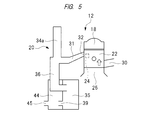
- FIG. 5 is a schematic view illustrating an operation of the engine of the present invention
- FIG. 6 is a schematic view illustrating the operation of the engine of the present invention
- FIG. 7 is a schematic view illustrating the operation of the engine of the present invention
- FIG. 8 is a schematic view illustrating the operation of the engine of the present invention
- FIG. 1 is a front cross-sectional view illustrating a portable working machine having an engine of the present invention
- FIG. 2 is an enlarged cross-sectional view illustrating a structural example of the engine of the present invention
- FIG. 3 is an outline view of the engine illustrated
- FIG. 9 is a schematic view illustrating the operation of the engine of the present invention.
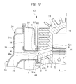
- FIG. 10 is an enlarged cross-sectional view illustrating another structural example of the engine of the present invention.
- FIG. 11 is an enlarged cross-sectional view illustrating another structural example of the engine of the present invention.
- FIG. 12 is an enlarged cross-sectional view illustrating another structural example of the engine of the present invention.
- FIG. 13 is an enlarged cross-sectional view illustrating another structural example of the engine of the present invention.
- FIG. 1 illustrates a cutter 10 working as the portable working machine, and the cutter 10 includes a body case 11; an engine 12 provided inside the body case 11; and a cutter blade 13 provided outside the body case 11.
- the cutter blade 13 corresponds to an operating member of the present invention.
- the cutter blade 13 is supported so as to be able to rotate, and is provided with a cover 14 for covering the cutter blade 13.
- a front handle 15 and a rear handle 16 are attached to outside of the body case 11, so that a worker can lift the cutter 10 with holding these front handle 15 and rear handle 16.
- the rear handle 16 is provided with a throttle lever 17.
- the throttle lever 17 is provided for adjusting the number of revolutions of the engine 12 by the worker.
- the engine 12 is an internal-combustion engine that burns a fuel-air mixture obtained by mixing a fuel and air in a combustion chamber 18 to generate power.
- the engine 12 has a cylinder 19, a muffler 20, and a fuel supply system 21. Inside the cylinder 19, a piston 22 is provided so as to be able to reciprocate in a direction along a center line A, The direction along the center line A is the cylinder axial direction in the present invention.
- the combustion chamber 18 is formed above the piston 22 inside the cylinder 19.
- the cylinder 19 is provided with a spark plug 23 exposed to the combustion chamber 18.
- a scavenging port 24 is formed on an inner surface of the cylinder 19, and the scavenging port 24 is connected to a crank chamber 25 via a scavenging passage.
- crankcase 26 is provided below the cylinder 19, and the crank chamber 25 is formed inside the crankcase 26.
- a crank shaft 27 is provided to the crank chamber 25 so as to be able to rotate, and a conrod (connecting rod) 28 is provided from the inside of the cylinder 19 to the crank chamber 25.
- the conrod 28 has one end connected to the crank shaft 27 and the other end connected to the piston 22.
- An air inlet pipe 29 is attached to the cylinder 19, an air intake passage 30 provided inside the air inlet pipe 29 is connected to the crack chamber 25.
- the fuel supply system 21 is provided on the upstream side upper than the air intake passage 30 in a direction of flow of air supplied to the air intake passage 30, and the fuel-air mixture consisting of the fuel and the air is supplied to the crank chamber 25 through the air intake passage 30.
- a first exhaust passage 31 is provided so as to penetrate through the cylinder 19 from its inner surface to its outer surface, and an exhaust port 32 is provided so as to connect the first exhaust passage 31 to inside of the cylinder 19.
- the exhaust port 32 is opened and closed by the movement of the piston 22.
- the exhaust port 32 is closed by the piston 22.
- the piston 22 moves in a first moving direction along the center line A in FIG. 1, that is, when the piston 22 moves up inside the cylinder 19, the exhaust port 32 is closed by the piston 22.
- the piston 22 moves in a second moving direction along the center line A in FIG. 1, that is, when the piston 22 moves down inside the cylinder 19, the exhaust port 32 is opened by the piston 22.
- the muffler 20 has an exhaust pipe 33, a branch pipe 34, a first expansion chamber 35, and a second expansion chamber 44.
- a second exhaust passage 36 is formed inside the exhaust pipe 33.
- the second exhaust passage 36 is connected to a downstream end of the first exhaust passage 31 in a direction of flow of an exhaust gas discharged from the exhaust port 32 to the first exhaust passage 31.
- a cross-sectional area of the first exhaust passage 31 is wider as the first exhaust passage 31 is closer to the second exhaust passage 36 in the direction of flow of the exhaust gas.
- the opening shape of the first exhaust passage 31 is approximately rectangular.
- a center line B of the first exhaust passage 31 in a top-and-bottom direction of the first exhaust passage 31 is extended so as to cross the center line A at a non-right angle.
- the center line B is tilted in a direction in which the center line B is farther away from a horizontal line as the center line B is closer to the second exhaust passage 36 in the direction of flow of the exhaust gas inside the first exhaust passage 31. More specifically, in state in which the center line A of the piston 22 extends along a vertical line, a center C of the downstream end of the first exhaust passage 31 is at a position lower than a center D of the exhaust port 32.
- the second exhaust passage 36 is extended substantially horizontally from the most upstream end toward the downstream side in the direction of flow of the exhaust gas, and then, is further extended downward through a curved part.
- the most downstream end of the second exhaust passage 36 is connected to the first expansion chamber 35.
- a cross-sectional area of the second exhaust passage 36 is wider as the second exhaust passage 36 is closer to the first expansion chamber 35 in the direction of flow of the exhaust gas.
- the first expansion chamber 35 is a space surrounded by a wall member 37 and a partition wall 38.
- the partition wall 38 is provided with a third exhaust passage 39.
- the third exhaust passage 39 connects the first expansion chamber 35 to the second expansion chamber 44, and the second expansion chamber 44 communicates with the outside of the muffler 20 via a fourth exhaust passage 45.
- the engine 12 of the present invention has a feature of a structure of a connecting part between the cylinder 19 and the muffler 20.
- the structure of the featured part of the engine 12 will be sequentially described below. (First Embodiment)
- an opening 31a is formed on the downstream end of the first exhaust passage 31.
- a gasket 40 is interposed between the wall member 37 and the cylinder 19.
- An opening 41 penetrating through the wall member 37 in a thickness direction is provided, and an opening 42 penetrating through the gasket 40 in a thickness direction is provided.
- the opening 41 corresponds to a connection passage of the present invention, and the first exhaust passage 31 is connected to the second exhaust passage 36 via the two openings 41 and 42.
- An opening 36a is formed on the upstream end of the second exhaust passage 36.
- a cross-sectional area of the opening 41 is larger than the largest value of a cross-sectional area of a branch passage 34a.
- a part of the exhaust pipe 33 is arranged in the first expansion chamber 35, and a flange 43 is provided to an end of an outer peripheral surface of the exhaust pipe 33 on the first exhaust passage 31 side.
- the flange 43 is an annular body protruding outward from the outer peripheral surface of the exhaust pipe 33, and the gasket 40 and the wall member 37 are interposed between the flange 43 and the cylinder 19.
- a screw member is inserted into a hole formed in the flange 43, and is tightened, so that the exhaust pipe 33, the wall member 37, and the gasket 40 are to fixed.
- Each of a shape of the opening 31a of the first exhaust passage 31, a shape of the opening 42 of the gasket 40, and a shape of the opening 36a of the second exhaust passage 36 is substantially rectangular, and four corners of each opening is curved. And, the openings 31a, 36a, and 42 are the same as each other in an opening width.
- the opening width is a width in the cylinder axial direction, that is, a width in the direction along the center line A. Also, in the direction along the center line A, upper and lower edges of the openings 31a, 36a, and 42 are at the same position as each other.
- the opening width of the opening 41 provided in the wall member 37 is narrower than the opening width of each of the openings 31a, 36a, and 42.
- the upper edge of the opening 41 is at the same position as a position of the upper edge at which each of the openings 31a, 36a, and 42 is formed.
- the lower edge 41b at which the opening 41 is formed is at a different position from a position of the lower edge at which each of the openings 31a, 36a, and 42 is formed.
- the lower edge 41b of the opening 41 is protruded upward by a predetermined degree from the lower edge 31c of the opening 31a and the lower edge of the second exhaust passage 36.
- a center E of the opening 41and the center C of the opening 31a are arranged at different positions from each other.
- a length from the center E to the upper edge 32a of the exhaust port 32 in the direction along the center line A is shorter than a length from the center C to the upper edge 32a.
- the upper edge 32a of the exhaust port 32 is an upper end of a part from which the exhaust port 32 is opened when the piston 22 moves toward a top dead center. In this manner, in the direction along the center line A, the center E is arranged upper than the center C.
- the branch passage 34a is provided inside the branch pipe 34.
- the second exhaust passage 36 is substantially horizontally arranged in an area from the opening 36a of the second exhaust passage 36 to a part where the second exhaust passage 36 is connected to the branch passage 34a, and a center line F of the second exhaust passage 36 in this area is at the same level as that of the center C of the opening 31a of the first exhaust passage 31.
- the center line B and the center line F intersect at the center C.
- the center line F is at a position lower than the center E of the opening 41.
- the branch passage 34a is branched from the second exhaust passage 36, and is extended upward from the branching point. Then, the branch passage 34a is substantially horizontally extended, and then, is extended downward, and an end thereof opposite to the second exhaust passage 36 is closed. A cross-sectional area of the branch passage 34a is constant from the second exhaust passage 36 to the closed end in the direction of flow of the exhaust gas. Note that the end of the branch passage 34a opposite to the second exhaust passage 36 may be closed or may be connected to the first expansion chamber 35 via a hole with a small diameter. In other words, the branch passage 34a may have only a structure that the pressure wave of the exhaust gas propagated from the second exhaust passage 36 can be reflected to the second exhaust passage 36.
- the piston 22 moves up toward the top dead center, and closes both of the scavenging port 24 and the exhaust port 32, so that a pressure inside the combustion chamber 18 increases, and ignition control is performed to the spark plug 23 at predetermined timing, which results in burning the air-fuel mixture in the combustion chamber 18, that is, causing the air-fuel mixture to explode.
- the positive pressure wave propagated from the second exhaust passage 36 to the first expansion chamber 35 reaches the most downstream end of the second exhaust passage 36, the positive pressure wave reverses as a negative pressure wave, and propagates in a reverse direction, that is, in a direction indicated with an arrow H as flowing back inside the second exhaust passage 36.
- the positive pressure wave propagated into the branch passage 34a reaches the downstream end of the branch passage 34a and is reflected thereon, and the reflected positive pressure wave propagates in a direction indicated with an arrow J as returning through the branch passage 34a toward the second exhaust passage 36.
- the scavenging port 24 is closed by the piston 22.
- the positive pressure wave propagated to the branch passage 34a is reflected on the downstream end of the branch passage 34a, and is returned to the second exhaust passage 36. And, from a period that the scavenging port 24 is closed by the moving up of the piston 22 to a period that the exhaust port 32 is closed, a part of the positive pressure wave reflected inside the branch passage 34a is propagated to the first exhaust passage 31 as indicated with an arrow L in FIG. 9. Therefore, the first exhaust passage 31 and the exhaust port 32 are maintained in a highly pressurized state.
- the engine 12 is the so-called two-stroke one-cycle engine in which one cycle of the air intake process, the scavenging process, the compressing process, the explosion process, and the exhaust process is performed in the course of the two strokes of the piston 22. And, the torque of the crank shaft 27 is transmitted to the cutter blade 13 via a power transmission mechanism so as to rotate the cutter blade 13.
- both of the positive pressure wave propagated from the first expansion chamber 35 to the second exhaust passage 36 and the positive pressure wave reflected inside the branch passage 34a and propagated to the second exhaust passage 36 are propagated to the first exhaust passage 31 and the exhaust port 32, so that the pressure in the exhaust port 32 can be maintained to be high.
- a fresh gas i.e., unburned gas to be flown from the combustion chamber 18 though the exhaust port 32 to the first exhaust passage 31 can be pushed back into the combustion chamber 18.
- the blowing of the unburned gas through it is suppressed by utilizing the pressure pulsation of the exhaust gas inside the muffler 20. Therefore, the deterioration of the exhaust gas property in the engine 12 can be suppressed, and the power of the engine can be improved.
- the opening 41 is provided between the first exhaust passage 31 and the second exhaust passage 36, and the center E of the opening 41 is at such a position as being closer to the upper edge 32a of the exhaust port 32 than the center C of the opening 31a in the direction along the center line A. That is, when the piston 22 moves toward the top dead center, the distance between the part where the exhaust port 32 is opened and the center E of the opening 41 can be shortened as short as possible.
- a direction of the pressure wave to be propagated from the second exhaust passage 36 to the first exhaust passage 31 is easy to be polarized or oriented toward the part of the exhaust port 32 where it is opened.
- the lower edge 41b of the opening 41 works as a weir for easily concentrating the pressure wave on the exhaust port 32.
- the cross-sectional area of the opening 41 provided in the wall member 37 can be set within a range from 0.7 to 1.3 times the maximum value of the cross-sectional area of the exhaust port 32.
- the maximum value of the cross-sectional area of the exhaust port 32 means the maximum value of the cross-sectional area obtained from the period that the scavenging port 24 is closed in the course of the moving up of the piston 22 to the period that the exhaust port 32 is closed. And, in the exhaust process of the engine 12, that is, when the exhaust port 32 is opened by the moving down of the piston 22, the cross-sectional area of the exhaust port 32 is wider as the piston 22 moves down lower.
- the cross-sectional area of the opening 41 is set to be equal to or less than 1.0 time the maximum value of the cross-sectional area of the exhaust port 32, the increase in the distribution resistance applied when the combustion gas passes through the opening 41 can be suppressed.
- the distance from the exhaust port 32 to the lower edge 41b can be set between 20 mm and 50 mm. This is because the pressure wave propagated from the second exhaust passage 36 to the first exhaust passage 31 is concentrated to flow toward the exhaust port 32 in a concentrated manner.
- the wall member 37 which is a single component makes up the first expansion chamber 35 and the opening 41.
- the branch passage 34a is connected to the middle of the second exhaust passage 36 in its length direction, and therefore, the muffler 20 can be downsized. That is, in order to downsize the engine 12 according to the present invention or reduce a weight of the engine, even if the lengths of the exhaust pipe 33 and the branch pipe 34 are shortened, even if the cross-sectional area and the volume of the second exhaust passage 36 are reduced, or even if the cross-sectional area and the volume of the branch passage 34a are reduced, the unburned gas can be caused to remain inside the combustion chamber 18. In other words, both of the effect of preventing the deterioration of the exhaust gas property of the engine 12 and the effect of downsizing or reducing the weight of the engine 12 can be simultaneously achieved.
- an effective length of the second exhaust passage 36 and an effective length of the branch passage 34a can be set when the engine speed is the normal number of revolutions, so that the pressure accumulated in the first expansion chamber 35 is propagated through the first exhaust passage 31 to the exhaust port 32 right before the exhaust port 32 is closed by the moving up of the piston 22.
- the cross-sectional area of the opening 41 be larger than the cross-sectional area of the most upstream end of the branch passage 34a.
- Such a configuration can suppress a pressure loss caused by the distribution resistance when the pressure wave reflected on the branch passage 34a and returned is propagated through the opening 41 to reach the exhaust port 32.
- the performance of causing the unburned gas to remain inside the combustion chamber 18 can be further improved.
- the opening 42 corresponds to the connection passage of the present invention, and the opening 31a of the first exhaust passage 31 is connected to the opening 36a of the second exhaust passage 36 via the openings 42 and 41.
- the center M of the opening 42 of the gasket 40 is arranged at a position different from the center C of the opening 31a in the direction along the center line A. More specifically, in the direction along the center line A, a length from the center M of the opening 42 of the gasket 40 to the upper edge 32a of the exhaust port 32 is shorter than a length from the center C of the opening 31a to the upper edge 32a of the exhaust port 32.
- a length from the center M to an opened part of the exhaust port 32 is shorter than a length from the center C to the opened part of the exhaust port 32.
- the center M is arranged upper than the center C.
- the center of the opening 41 and the center C of the opening 31a are at the same position as each other in the direction along the center line A.
- Other structures of the engine 12 of FIG. 10 are the same as those of the engine 12 of FIGs. 1 to 3.
- the operation of the engine 12 of FIG. 10 is the same as the operation of the engine 12 described with FIGs. 5 to 9. Also, in the engine 12 of FIG. 10, in the direction along the center line A, a length from the center M of the opening 42 to the upper edge 32a of the exhaust port 32 is shorter than a length from the center C to the upper edge 32a of the exhaust port 32.
- the pressure wave propagated through the second exhaust passage 36 to the exhaust port 32 can be concentrated to the opened part of the exhaust port 32, and therefore, the same effect as the effect of the first embodiment of the engine 12 can be obtained.
- the deterioration of the exhaust gas property can be prevented by designing an opening width of the opening 42 provided in the gasket 40 and a position of the same in a height direction. Therefore, the increase in the number of components can be prevented without providing a dedicated component.
- FIG. 11 In the engine 12 illustrated in FIG. 11, in the direction of the center line A, the lower edges of the openings 31a, 41, and 42 are at the same position as each other, and the lower edge of the flange 43 protrudes upward from the lower edges of the openings 31a, 41, and 42. Also, an end of the exhaust pipe 33 on the first exhaust passage 31 side is bent so as to ride over the lower edge of the flange 43. That is, the cross-sectional area of the opening 36a formed on the upstream end of the second exhaust passage 36 is smaller than the cross-sectional area of each of the openings 31a, 41, and 42. This opening 36a corresponds to the connection passage of the present invention.
- the center N of the opening 36a is arranged at a position different from the center C of the opening 31a. More specifically, in the direction along the center line A, a length from the center N of the opening 36a to the upper edge 32a of the exhaust port 32 is shorter than a length from the center C of the opening 31a to the upper edge 32a of the exhaust port 32. In this manner, in the direction along the center line A, the center N is arranged upper than the center C.
- Other structures of the engine 12 of FIG. 11 are the same as those of the engine 12 of FIGs. 1 to 3.
- the operation of the engine 12 of FIG. 11 is the same as the operation of the engine 12 described with FIGs. 5 to 9. Also, in the engine 12 of FIG. 11, in the direction along the center line A, the length from the center N of the opening 36a to the upper edge 32a of the exhaust port 32 is shorter than the length from the center C of the opening 31a to the upper edge 32a of the exhaust port 32. In other words, in the direction along the center line A, the distance between the opened part of the exhaust port 32 and the center N is set to be small as short as possible.
- the pressure wave propagated through the opening 36a of the second exhaust passage 36 to the exhaust port 32 can be concentrated on the vicinity of the exhaust port 32, so that the same effect as the effect of the first embodiment of the engine 12 can be obtained.
- the deterioration of the exhaust gas property can be prevented by designing the opening width of the opening 36a and the position thereof in height direction. Therefore, the increase in the number of components can be prevented without providing a dedicated component.
- other structures than the structures of the position and the opening width of the opening 36a can be designed to be the same as those of the engine 12 of FIG. 2, and the same effect as the engine 12 of FIG. 2 can be obtained.
- FIG. 12 In the engine 12 illustrated in FIG. 12, in the direction of the center line A, the lower edges of the openings 31a, 41, and 42 are at the same position as each other, and the lower edge of the flange 43 protrudes upward from the lower edges of the openings 31a, 41, and 42. Also, an end of the exhaust pipe 33 on the first exhaust passage 31 side rides over the lower edge of the flange 43. In the engine 12 of FIG. 12, this opening 36a corresponds to the connection passage of the present invention. And, in the direction along the center line A, the center N of the opening 36a is arranged at a position different from the center C of the opening 31a. More specifically, in the direction along the center line A, a length from the opening 36a to the upper edge 32a of the exhaust port 32 is shorter than a length from the center N of the opening 31a to the upper edge 32a of the exhaust port 32.
- an upper wall 36b is substantially horizontally extended, and a lower wall 36c is extended so as to tile.
- the lower wall 36c is tilted in a direction in which a gap between the lower wall 36c and the upper wall 36b is smaller as the lower wall 36c comes closer to the opening 36a. More specifically, an inner surface of the lower wall 36c is in parallel with the center line B.
- Other structures of the engine 12 of FIG. 12 are the same as those of the engine 12 of FIGs. 1 to 3.
- the operation of the engine 12 of FIG. 12 is the same as the operation of the engine 12 described with FIGs. 5 to 9. Also, in the engine 12 of FIG. 12, in the direction along the center line A, the center N of the opening 36a is at a position different from the opening 31a. In other words, in the direction along the center line A, the distance between an opened part of the exhaust port 32 and the center N is set to be smaller as short as possible. In this manner, in the direction along the center line A, the center N is arranged upper than the center C.
- the pressure wave propagated through the opening 36a of the second exhaust passage 36 to the exhaust port 32 can be concentrated on the vicinity of the exhaust port 32, so that the same effect as the effect of the first embodiment of the engine 12 can be obtained.
- an inner surface of the upper wall 36b is horizontal while the lower wall 36c is tilted in the direction in which the gap between the lower wall 36c and the upper wall 36b becomes smaller as the lower wall 36c comes closer to the opening 36a.
- the pressure wave propagated through the opening 36a of the second exhaust passage 36 to the exhaust port 32 can be further concentrated on the vicinity of the exhaust port 32.
- the deterioration of the exhaust gas property can be prevented by designing the shape of the flange 43 and the structure of the exhaust pipe 33 so as to adjust the opening width of the opening 36a and the position thereof in the height direction. Therefore, the increase in the number of components can be prevented without providing a dedicated component.
- other structures than the structures of the position and the opening width of the opening 36a can be designed to be the same as those of the engine 12 of FIG. 2, so that the same effect as that of the engine 12 of FIG. 2 can be obtained.
- FIG. 13 In the engine 12 illustrated in FIG. 13, in the direction along the center line A, the lower edges of the openings 31a, 36a, and 42 are at the same position as each other, a part of the wall member 37 is protruded to reach a position closer to the center line F than the lower edges of the openings 31a, 36a, and 42, and a protruding portion 37b extending from the position through a cured portion 37a toward the first exhaust passage 31 is provided.
- the protruding portion 37b is arranged over the openings 31a and 42, and the opening 41 is formed above the protruding portion 37b.
- the cured portion 37a has a curved surface 37c continuously formed from an inner surface of the opening 41.
- the protruding portion 37b is positioned so as to be lower than the center C of the opening 31a, and the center P of the opening 41 is at a position higher than the center C.
- the opening 41 corresponds to the connection passage of the present invention.
- Other structures of the engine 12 of FIG. 13 are the same as those of the engine 12 of FIGs. 1 to 3.
- the center P of the opening 41 is at a position different from the center C of the opening 31a. That is, at a stage before the exhaust port 32 is closed by the moving of the piston 22, a length from the center P to an opened part of the exhaust port 32 in the direction along the center line A is shorter than a length from the center C to the opened part of the exhaust port 32. In this manner, in the direction along the center line A, the center P is arranged upper than the center C.
- the pressure wave propagated through the opening 36a of the second exhaust passage 36 to the exhaust port 32 can be concentrated on the vicinity of the exhaust port 32, so that the same effect as the effect of the first embodiment of the engine 12 can be obtained.
- the wall member 37 is provided with the curved portion 37a, and the pressure wave is propagated along a surface of the curved portion 37a so as to trace in a curved or arced shape. This can suppress a pressure loss caused when the pressure wave is propagated through the opening 36a of the second exhaust passage 36 to the exhaust port 32.
- the deterioration of the exhaust gas property can be prevented by designing the shape of the wall member 37 so as to adjust the opening width of the opening 41 and the position of the center P of the opening 41 in the direction along the center line A. Therefore, the increase in the number of components can be prevented without providing a dedicated component.
- the engine 12 of FIG. 13 note that other structures than the structure of the shape of the wall member 37 can be designed to be the same as those of the engine 12 of FIG. 2, and the same effect as the engine 12 of FIG. 2 can be obtained.
- the engine and the portable working machine of the present invention are not limited to the above-described embodiments, and various modifications and alterations can be made within the scope of the present invention.
- the engine of the present invention includes not only an engine with such a structure that the center line A is arranged along the vertical line but also an engine with such a structure that the center line A is tilted from the vertical line.
- the engine of the present invention includes not only an engine with such a structure that the center line A and the center line B cross each other at a non-right angle but also an engine with such a structure that the center line A and the center line B cross each other at a substantially right angle.
- the cross-sectional shapes of the openings and the cross-sectional shapes of the connection passages in the present invention include an elliptical shape and a circular shape.
- the portable working machine of the present invention is an engine-operated tool that transmits power of an engine serving as a power source to an operating member
- the portable working machine includes not only the above-described cutter but also a blower, a hedge trimmer, a drill, a cultivator, a chainsaw, a grass cutter, etc.
- the operating member of the grass cutter is a mowing blade.
- the operating member of the chainsaw is a chain-form blade.
- the operating member of the blower is an impeller.
- the operating member of the cultivator is a soil-digging blade.
- the operating member of the hedge trimmer is a blade.
- the operating member of the drill is a boring blade.
- the operating members of the present invention include an operating member that rotates, an operating member that reciprocates, and an operating member that circulates along a circular track.
- the present invention can be utilized for an engine used as a power source in a portable working machine such as a chainsaw and a cutter.
Landscapes
- Engineering & Computer Science (AREA)
- Chemical & Material Sciences (AREA)
- Combustion & Propulsion (AREA)
- Mechanical Engineering (AREA)
- General Engineering & Computer Science (AREA)
- Exhaust Silencers (AREA)
- Cylinder Crankcases Of Internal Combustion Engines (AREA)
Abstract
An engine that can suppress decrease in a function of causing an unburned gas to remain in a combustion chamber is provided. An engine 12 has a combustion chamber 18 provided inside a cylinder 19, in which an exhaust port 32 connected to the combustion chamber 18 is opened and closed by a piston 22 reciprocating inside the cylinder 19. The engine 12 includes: a first exhaust passage 31 provided in the cylinder 19 and connected to the exhaust port 32; an opening 31a formed on the downstream end of the first exhaust passage 31 in a direction of discharge of a combustion gas discharged from the exhaust port 32; and a second exhaust passage 36 connected to the opening 31a via a connection passage 41. The center E of the connection passage 41 in a cylinder axial direction and the center C of the opening 31a in the cylinder axial direction are arranged at different positions from each other in the cylinder axial direction.
Description
The present invention relates to an engine used as a power source in a portable working machine such as a chainsaw and a cutter, and to a portable working machine equipped with the engine.
For most of portable working machines such as chainsaws and cutters, an engine serving as a power source is required to have high power, to be downsized, and to be light, and therefore, usage of a two-stroke one-cycle engine as the power source is mainstream. In the two-stroke one-cycle engine, unburned gas is discharged from an exhaust port of a combustion chamber during the exhaust and scavenging processes in the engine, and the exhaust gas property is deteriorated. Accordingly, in order to suppress the deterioration of the exhaust gas property in the two-stroke one-cycle engine, a catalytic method, an air-lead scavenging method, an exhaust-pulse method, etc., are adopted.
In the catalytic method, a catalyst is arranged in a discharge passage of the exhaust gas for purifying the exhaust gas. The air-lead scavenging method is a method of leading air in a scavenging passage to the combustion chamber during the exhaust and scavenging processes of the engine before the unburned gas is discharged from the combustion chamber. Also, the exhaust-pulse scavenging method is a method of causing the unburned gas to remain in the combustion chamber by propagating a pressure wave of a combustion gas, that is discharged from the exhaust port, to the exhaust port at a later stage of the exhaust process of the engine. The patent literature 1 describes an example of an engine having a structure which suppresses the deterioration of the exhaust gas property by the exhaust-pulse scavenging method of the above-described methods and an example of a portable working machine equipped with the engine.
This engine described in the patent literature 1 has an exhaust pipe provided on downstream of the exhaust port and a branch pipe branched from the exhaust pipe. A downstream end of the exhaust pipe is connected to outside of a muffler via an expansion chamber. In the engine described in the patent literature 1, the exhaust gas is discharged from the combustion chamber to the exhaust pipe, pressure inside the expansion chamber is propagated through the exhaust pipe to the vicinity of the exhaust port right before the end of the exhaust process, and the pressure reflected inside the branch pipe is propagated through the exhaust pipe to the vicinity of the exhaust port. Thus, the pressure in the vicinity of the exhaust port right before the end of the exhaust process is lifted up, and the unburned gas remains inside the combustion chamber, so that the deterioration of the exhaust gas property can be suppressed, and the engine power can be improved.
However, in order to suppress the outflow of the exhaust gas, it is required to further enhance the effect of the propagation of the pressure wave.
A preferred aim of the present invention is to provide an engine that further improves a function of causing the unburned gas to remain in the combustion chamber and provide a portable working machine equipped with the engine.
An engine according to an embodiment is an engine having a combustion chamber provided inside a cylinder, in which an exhaust port connected to the combustion chamber is opened and closed by a piston reciprocating inside the cylinder. The engine includes: a first exhaust passage provided in the cylinder and connected to the exhaust port; an opening formed on a downstream end of the first exhaust passage in a direction of discharge of the combustion gas discharged from the exhaust port; and a second exhaust passage connected to the opening via a connection passage, and center of the connection passage in a cylinder axial direction and center of the opening in the cylinder axial direction are arranged at different positions from each other in the cylinder axial direction.
A portable working machine according to another embodiment is a portable working machine including: an engine in which a combustion chamber is provided inside a cylinder and an exhaust port connected to the combustion chamber is opened and closed by a piston reciprocating inside the cylinder, and an operating member that is operated by power transmitted from the engine to the operating member. In the portable working machine, the engine includes: a first exhaust passage provided in the cylinder and connected to the exhaust port; an opening formed on a downstream end of the first exhaust passage in a direction of discharge of the combustion gas discharged from the exhaust port; and a second exhaust passage connected to the opening via a connection passage, and a center of the connection passage in a cylinder axial direction and a center of the opening in the cylinder axial direction are arranged at different positions from each other in the cylinder axial direction.
According to an engine of the present invention, pressure wave to be propagated from the second exhaust passage through the connection passage to the exhaust port is easily propagated to the exhaust port, so that decrease in the function of causing the unburned gas to remain in the combustion chamber can be suppressed.
Embodiments of an engine of the present invention and embodiments of a portable working machine equipped with the engine will be described in detail with reference to FIGs. 1 to 4. FIG. 1 illustrates a cutter 10 working as the portable working machine, and the cutter 10 includes a body case 11; an engine 12 provided inside the body case 11; and a cutter blade 13 provided outside the body case 11. The cutter blade 13 corresponds to an operating member of the present invention. The cutter blade 13 is supported so as to be able to rotate, and is provided with a cover 14 for covering the cutter blade 13. A front handle 15 and a rear handle 16 are attached to outside of the body case 11, so that a worker can lift the cutter 10 with holding these front handle 15 and rear handle 16. Note that the rear handle 16 is provided with a throttle lever 17. The throttle lever 17 is provided for adjusting the number of revolutions of the engine 12 by the worker.
The engine 12 is an internal-combustion engine that burns a fuel-air mixture obtained by mixing a fuel and air in a combustion chamber 18 to generate power. The engine 12 has a cylinder 19, a muffler 20, and a fuel supply system 21. Inside the cylinder 19, a piston 22 is provided so as to be able to reciprocate in a direction along a center line A, The direction along the center line A is the cylinder axial direction in the present invention. In FIGs. 1 and 2, the combustion chamber 18 is formed above the piston 22 inside the cylinder 19. Also, the cylinder 19 is provided with a spark plug 23 exposed to the combustion chamber 18. Further, a scavenging port 24 is formed on an inner surface of the cylinder 19, and the scavenging port 24 is connected to a crank chamber 25 via a scavenging passage.
Meanwhile, a crankcase 26 is provided below the cylinder 19, and the crank chamber 25 is formed inside the crankcase 26. A crank shaft 27 is provided to the crank chamber 25 so as to be able to rotate, and a conrod (connecting rod) 28 is provided from the inside of the cylinder 19 to the crank chamber 25. The conrod 28 has one end connected to the crank shaft 27 and the other end connected to the piston 22.
An air inlet pipe 29 is attached to the cylinder 19, an air intake passage 30 provided inside the air inlet pipe 29 is connected to the crack chamber 25. The fuel supply system 21 is provided on the upstream side upper than the air intake passage 30 in a direction of flow of air supplied to the air intake passage 30, and the fuel-air mixture consisting of the fuel and the air is supplied to the crank chamber 25 through the air intake passage 30. A first exhaust passage 31 is provided so as to penetrate through the cylinder 19 from its inner surface to its outer surface, and an exhaust port 32 is provided so as to connect the first exhaust passage 31 to inside of the cylinder 19.
The exhaust port 32 is opened and closed by the movement of the piston 22. When the piston 22 moves in a first moving direction along the center line A in FIG. 1, that is, when the piston 22 moves up inside the cylinder 19, the exhaust port 32 is closed by the piston 22. On the other hand, when the piston 22 moves in a second moving direction along the center line A in FIG. 1, that is, when the piston 22 moves down inside the cylinder 19, the exhaust port 32 is opened by the piston 22.
The muffler 20 has an exhaust pipe 33, a branch pipe 34, a first expansion chamber 35, and a second expansion chamber 44. A second exhaust passage 36 is formed inside the exhaust pipe 33. The second exhaust passage 36 is connected to a downstream end of the first exhaust passage 31 in a direction of flow of an exhaust gas discharged from the exhaust port 32 to the first exhaust passage 31. A cross-sectional area of the first exhaust passage 31 is wider as the first exhaust passage 31 is closer to the second exhaust passage 36 in the direction of flow of the exhaust gas. As illustrated in FIG. 4, in a side view of the first exhaust passage 31, the opening shape of the first exhaust passage 31 is approximately rectangular.
Also, a center line B of the first exhaust passage 31 in a top-and-bottom direction of the first exhaust passage 31 is extended so as to cross the center line A at a non-right angle. The center line B is tilted in a direction in which the center line B is farther away from a horizontal line as the center line B is closer to the second exhaust passage 36 in the direction of flow of the exhaust gas inside the first exhaust passage 31. More specifically, in state in which the center line A of the piston 22 extends along a vertical line, a center C of the downstream end of the first exhaust passage 31 is at a position lower than a center D of the exhaust port 32.
Meanwhile the second exhaust passage 36 is extended substantially horizontally from the most upstream end toward the downstream side in the direction of flow of the exhaust gas, and then, is further extended downward through a curved part. The most downstream end of the second exhaust passage 36 is connected to the first expansion chamber 35. A cross-sectional area of the second exhaust passage 36 is wider as the second exhaust passage 36 is closer to the first expansion chamber 35 in the direction of flow of the exhaust gas. Further, the first expansion chamber 35 is a space surrounded by a wall member 37 and a partition wall 38. The partition wall 38 is provided with a third exhaust passage 39. The third exhaust passage 39 connects the first expansion chamber 35 to the second expansion chamber 44, and the second expansion chamber 44 communicates with the outside of the muffler 20 via a fourth exhaust passage 45.
The engine 12 of the present invention has a feature of a structure of a connecting part between the cylinder 19 and the muffler 20. The structure of the featured part of the engine 12 will be sequentially described below.
(First Embodiment)
(First Embodiment)
A first embodiment of the engine 12 will be described with reference to FIG. 2. First, an opening 31a is formed on the downstream end of the first exhaust passage 31. Also, a gasket 40 is interposed between the wall member 37 and the cylinder 19. An opening 41 penetrating through the wall member 37 in a thickness direction is provided, and an opening 42 penetrating through the gasket 40 in a thickness direction is provided. The opening 41 corresponds to a connection passage of the present invention, and the first exhaust passage 31 is connected to the second exhaust passage 36 via the two openings 41 and 42. An opening 36a is formed on the upstream end of the second exhaust passage 36. A cross-sectional area of the opening 41 is larger than the largest value of a cross-sectional area of a branch passage 34a. In this specification, note that the "upstream" and the "downstream" means the "upstream" and the "downstream" in the direction of discharge of the combustion gas discharged from the exhaust port 32.
Further, a part of the exhaust pipe 33 is arranged in the first expansion chamber 35, and a flange 43 is provided to an end of an outer peripheral surface of the exhaust pipe 33 on the first exhaust passage 31 side. The flange 43 is an annular body protruding outward from the outer peripheral surface of the exhaust pipe 33, and the gasket 40 and the wall member 37 are interposed between the flange 43 and the cylinder 19. And, a screw member is inserted into a hole formed in the flange 43, and is tightened, so that the exhaust pipe 33, the wall member 37, and the gasket 40 are to fixed.
Each of a shape of the opening 31a of the first exhaust passage 31, a shape of the opening 42 of the gasket 40, and a shape of the opening 36a of the second exhaust passage 36 is substantially rectangular, and four corners of each opening is curved. And, the openings 31a, 36a, and 42 are the same as each other in an opening width. Here, the opening width is a width in the cylinder axial direction, that is, a width in the direction along the center line A. Also, in the direction along the center line A, upper and lower edges of the openings 31a, 36a, and 42 are at the same position as each other. On the other hand, the opening width of the opening 41 provided in the wall member 37 is narrower than the opening width of each of the openings 31a, 36a, and 42.
Also, in the direction along the center line A, the upper edge of the opening 41 is at the same position as a position of the upper edge at which each of the openings 31a, 36a, and 42 is formed. Further, in the direction along the center line A, the lower edge 41b at which the opening 41 is formed is at a different position from a position of the lower edge at which each of the openings 31a, 36a, and 42 is formed.
That is, the lower edge 41b of the opening 41 is protruded upward by a predetermined degree from the lower edge 31c of the opening 31a and the lower edge of the second exhaust passage 36. And, in the direction along the center line A, a center E of the opening 41and the center C of the opening 31a are arranged at different positions from each other. In more specific explanation, a length from the center E to the upper edge 32a of the exhaust port 32 in the direction along the center line A is shorter than a length from the center C to the upper edge 32a. The upper edge 32a of the exhaust port 32 is an upper end of a part from which the exhaust port 32 is opened when the piston 22 moves toward a top dead center. In this manner, in the direction along the center line A, the center E is arranged upper than the center C.
Further, the branch passage 34a is provided inside the branch pipe 34. In the direction of flow of the exhaust gas, the second exhaust passage 36 is substantially horizontally arranged in an area from the opening 36a of the second exhaust passage 36 to a part where the second exhaust passage 36 is connected to the branch passage 34a, and a center line F of the second exhaust passage 36 in this area is at the same level as that of the center C of the opening 31a of the first exhaust passage 31. In other words, the center line B and the center line F intersect at the center C. Also, the center line F is at a position lower than the center E of the opening 41.
The branch passage 34a is branched from the second exhaust passage 36, and is extended upward from the branching point. Then, the branch passage 34a is substantially horizontally extended, and then, is extended downward, and an end thereof opposite to the second exhaust passage 36 is closed. A cross-sectional area of the branch passage 34a is constant from the second exhaust passage 36 to the closed end in the direction of flow of the exhaust gas. Note that the end of the branch passage 34a opposite to the second exhaust passage 36 may be closed or may be connected to the first expansion chamber 35 via a hole with a small diameter. In other words, the branch passage 34a may have only a structure that the pressure wave of the exhaust gas propagated from the second exhaust passage 36 can be reflected to the second exhaust passage 36.
In a case that the engine 12 structured as described above is rotated at the normal number of revolutions such as 9,000 rpm, the flow of the exhaust gas inside the engine 12 and inside the muffler 20 and a propagation state of the pressure wave of the exhaust gas will be described with reference to FIGs. 1, 2, and 5 to 9. As illustrated in FIG. 5, the piston 22 moves up toward the top dead center, and closes both of the scavenging port 24 and the exhaust port 32, so that a pressure inside the combustion chamber 18 increases, and ignition control is performed to the spark plug 23 at predetermined timing, which results in burning the air-fuel mixture in the combustion chamber 18, that is, causing the air-fuel mixture to explode.
By the above-described explosion process, a temperature and a pressure inside the combustion chamber 18 become high, and besides, the piston 22 is moved down. When the exhaust port 32 is opened as illustrated in FIG. 6 by the moving down of the piston 22, the combustion gas in the combustion chamber 18 is discharged through the exhaust port 32 and the first exhaust passage 31 to the second exhaust passage 36. In this exhaust process, a positive pressure wave propagates to the second exhaust passage 36 and the branch passage 34a as indicated with an arrow G. When the positive pressure wave propagated from the second exhaust passage 36 to the first expansion chamber 35 reaches the most downstream end of the second exhaust passage 36, the positive pressure wave reverses as a negative pressure wave, and propagates in a reverse direction, that is, in a direction indicated with an arrow H as flowing back inside the second exhaust passage 36.
Meanwhile, the positive pressure wave propagated into the branch passage 34a reaches the downstream end of the branch passage 34a and is reflected thereon, and the reflected positive pressure wave propagates in a direction indicated with an arrow J as returning through the branch passage 34a toward the second exhaust passage 36. During the above-described operation, the scavenging port 24 is closed by the piston 22.
When the scavenging port 24 is opened by further moving down of the piston 22 as illustrated in FIG. 7, the fuel-air mixture inside the crank chamber 25 is sucked into the combustion chamber 18 via the scavenging port 24, and besides, the combustion gas inside the combustion chamber 18 is discharged to the first exhaust passage 31. That is, an air intake process and a scavenging process are simultaneously performed. At an initial stage at which the scavenging port 24 is opened, such a negative pressure wave in the direction indicated with the arrow H as returning and propagating inside the second exhaust passage 36 and such a positive pressure wave in the direction indicated with the arrow J as being reflected and propagating inside the branch passage 34a are synthesized with each other. As a result, back pressures of the exhaust port 32 and the first exhaust passage 31 are decreased.
From a period that the opening of the exhaust port 32 to a period that the piston 22 reaches a bottom dead center, the combustion gas inside the combustion chamber 18 is discharged through the exhaust port 32, the first exhaust passage 31, and the second exhaust passage 36 to the first expansion chamber 35, and besides, the combustion gas is discharged from first expansion chamber 35 through the second expansion chamber 44 to the outside of the muffler 20.
On the other hand, when the piston 22 reaches the bottom dead center and the movement direction thereof is reversed, which results in moving up of the piston 22 to close the scavenging port 24, the positive pressure wave of the combustion gas remaining inside the first expansion chamber 35 is propagated to the second exhaust passage 36 as indicated with an arrow K in FIG. 8. And, a part of the positive pressure wave propagated to the second exhaust passage 36 after passing through the branching point between the second exhaust passage 36 and the branch passage 34a is propagated into the branch passage 34a, and the rest is propagated toward the first exhaust passage 31. As a result, pressures in the first exhaust passage 31 and the exhaust port 32 are increased.
The positive pressure wave propagated to the branch passage 34a is reflected on the downstream end of the branch passage 34a, and is returned to the second exhaust passage 36. And, from a period that the scavenging port 24 is closed by the moving up of the piston 22 to a period that the exhaust port 32 is closed, a part of the positive pressure wave reflected inside the branch passage 34a is propagated to the first exhaust passage 31 as indicated with an arrow L in FIG. 9. Therefore, the first exhaust passage 31 and the exhaust port 32 are maintained in a highly pressurized state.
When the exhaust port 32 is closed by further moving up of the piston 22, the procedure proceeds to a compressing process for compressing the fuel-air mixture inside the combustion chamber 18, and then, returns to the above explosion process. Hereinafter, the explosion process, the exhaust process, the scavenging process, and the air intake process are repeated so as to convert the reciprocating power of the piston 22 into the torque of the crank shaft 27. The engine 12 according to this embodiment is the so-called two-stroke one-cycle engine in which one cycle of the air intake process, the scavenging process, the compressing process, the explosion process, and the exhaust process is performed in the course of the two strokes of the piston 22. And, the torque of the crank shaft 27 is transmitted to the cutter blade 13 via a power transmission mechanism so as to rotate the cutter blade 13.
As described above, according to the engine 12 of this embodiment, from the period that the exhaust port 24 is closed by the moving up of the piston 22 to the period that the exhaust port 32 is closed, both of the positive pressure wave propagated from the first expansion chamber 35 to the second exhaust passage 36 and the positive pressure wave reflected inside the branch passage 34a and propagated to the second exhaust passage 36 are propagated to the first exhaust passage 31 and the exhaust port 32, so that the pressure in the exhaust port 32 can be maintained to be high.
Therefore, a fresh gas, i.e., unburned gas to be flown from the combustion chamber 18 though the exhaust port 32 to the first exhaust passage 31 can be pushed back into the combustion chamber 18. In other words, the blowing of the unburned gas through it is suppressed by utilizing the pressure pulsation of the exhaust gas inside the muffler 20. Therefore, the deterioration of the exhaust gas property in the engine 12 can be suppressed, and the power of the engine can be improved.
More particularly, in the engine 12 of this embodiment, the opening 41 is provided between the first exhaust passage 31 and the second exhaust passage 36, and the center E of the opening 41 is at such a position as being closer to the upper edge 32a of the exhaust port 32 than the center C of the opening 31a in the direction along the center line A. That is, when the piston 22 moves toward the top dead center, the distance between the part where the exhaust port 32 is opened and the center E of the opening 41 can be shortened as short as possible.
Therefore, a direction of the pressure wave to be propagated from the second exhaust passage 36 to the first exhaust passage 31 is easy to be polarized or oriented toward the part of the exhaust port 32 where it is opened. In other words, the lower edge 41b of the opening 41 works as a weir for easily concentrating the pressure wave on the exhaust port 32. Hence, in the engine 12, the performance of causing the unburned gas to remain inside the combustion chamber 18 is further improved.
Also, the cross-sectional area of the opening 41 provided in the wall member 37 can be set within a range from 0.7 to 1.3 times the maximum value of the cross-sectional area of the exhaust port 32. The maximum value of the cross-sectional area of the exhaust port 32 means the maximum value of the cross-sectional area obtained from the period that the scavenging port 24 is closed in the course of the moving up of the piston 22 to the period that the exhaust port 32 is closed. And, in the exhaust process of the engine 12, that is, when the exhaust port 32 is opened by the moving down of the piston 22, the cross-sectional area of the exhaust port 32 is wider as the piston 22 moves down lower. For this reason, even if the cross-sectional area of the opening 41 is set to be equal to or less than 1.0 time the maximum value of the cross-sectional area of the exhaust port 32, the increase in the distribution resistance applied when the combustion gas passes through the opening 41 can be suppressed.
Also, in the direction along the center line B of the first exhaust passage 31 and the center line F of the second exhaust passage 36, the distance from the exhaust port 32 to the lower edge 41b can be set between 20 mm and 50 mm. This is because the pressure wave propagated from the second exhaust passage 36 to the first exhaust passage 31 is concentrated to flow toward the exhaust port 32 in a concentrated manner.
Also, the wall member 37 which is a single component makes up the first expansion chamber 35 and the opening 41. As a result, the increase in the number of components of the engine 12 can be suppressed, and the increase in the manufacturing cost of the engine 12 can be suppressed, so that the inexpensive engine 12 can be provided.
Further, in the direction of flow of the exhaust gas, the branch passage 34a is connected to the middle of the second exhaust passage 36 in its length direction, and therefore, the muffler 20 can be downsized. That is, in order to downsize the engine 12 according to the present invention or reduce a weight of the engine, even if the lengths of the exhaust pipe 33 and the branch pipe 34 are shortened, even if the cross-sectional area and the volume of the second exhaust passage 36 are reduced, or even if the cross-sectional area and the volume of the branch passage 34a are reduced, the unburned gas can be caused to remain inside the combustion chamber 18. In other words, both of the effect of preventing the deterioration of the exhaust gas property of the engine 12 and the effect of downsizing or reducing the weight of the engine 12 can be simultaneously achieved.
Also, an effective length of the second exhaust passage 36 and an effective length of the branch passage 34a can be set when the engine speed is the normal number of revolutions, so that the pressure accumulated in the first expansion chamber 35 is propagated through the first exhaust passage 31 to the exhaust port 32 right before the exhaust port 32 is closed by the moving up of the piston 22.
Further, it is preferred that the cross-sectional area of the opening 41 be larger than the cross-sectional area of the most upstream end of the branch passage 34a. Such a configuration can suppress a pressure loss caused by the distribution resistance when the pressure wave reflected on the branch passage 34a and returned is propagated through the opening 41 to reach the exhaust port 32. Hence, in the engine 12, the performance of causing the unburned gas to remain inside the combustion chamber 18 can be further improved.
(Second Embodiment)
(Second Embodiment)
Next, a second embodiment of the engine 12 will be described with reference to FIG. 10. In the engine 12 of FIG. 10, the opening 42 corresponds to the connection passage of the present invention, and the opening 31a of the first exhaust passage 31 is connected to the opening 36a of the second exhaust passage 36 via the openings 42 and 41. In the engine 12 illustrated in FIG. 10, the center M of the opening 42 of the gasket 40 is arranged at a position different from the center C of the opening 31a in the direction along the center line A. More specifically, in the direction along the center line A, a length from the center M of the opening 42 of the gasket 40 to the upper edge 32a of the exhaust port 32 is shorter than a length from the center C of the opening 31a to the upper edge 32a of the exhaust port 32.
In other words, in the direction along the center line A, a length from the center M to an opened part of the exhaust port 32 is shorter than a length from the center C to the opened part of the exhaust port 32. In this manner, in the direction along the center line A, the center M is arranged upper than the center C. Also, in the engine 12 of FIG. 10, the center of the opening 41 and the center C of the opening 31a are at the same position as each other in the direction along the center line A. Other structures of the engine 12 of FIG. 10 are the same as those of the engine 12 of FIGs. 1 to 3.
The operation of the engine 12 of FIG. 10 is the same as the operation of the engine 12 described with FIGs. 5 to 9. Also, in the engine 12 of FIG. 10, in the direction along the center line A, a length from the center M of the opening 42 to the upper edge 32a of the exhaust port 32 is shorter than a length from the center C to the upper edge 32a of the exhaust port 32.
As a result, from the period that the scavenging port 24 is closed by the moving up of the piston 22 to the period that the exhaust port 32 is closed, the pressure wave propagated through the second exhaust passage 36 to the exhaust port 32 can be concentrated to the opened part of the exhaust port 32, and therefore, the same effect as the effect of the first embodiment of the engine 12 can be obtained. Also, in the engine 12 of FIG. 10, the deterioration of the exhaust gas property can be prevented by designing an opening width of the opening 42 provided in the gasket 40 and a position of the same in a height direction. Therefore, the increase in the number of components can be prevented without providing a dedicated component. In the engine 12 of FIG. 10, note that other structures than the structures of the position and the opening width of the opening 42 of the gasket 40 can be designed to be the same as those of the engine 12 of FIG. 2, and the same effect as the engine 12 of FIG. 2 can be obtained.
(Third Embodiment)
(Third Embodiment)
Next, a third embodiment of the engine 12 will be described with reference to FIG. 11. In the engine 12 illustrated in FIG. 11, in the direction of the center line A, the lower edges of the openings 31a, 41, and 42 are at the same position as each other, and the lower edge of the flange 43 protrudes upward from the lower edges of the openings 31a, 41, and 42. Also, an end of the exhaust pipe 33 on the first exhaust passage 31 side is bent so as to ride over the lower edge of the flange 43. That is, the cross-sectional area of the opening 36a formed on the upstream end of the second exhaust passage 36 is smaller than the cross-sectional area of each of the openings 31a, 41, and 42. This opening 36a corresponds to the connection passage of the present invention.
And, in the direction along the center line A, the center N of the opening 36a is arranged at a position different from the center C of the opening 31a. More specifically, in the direction along the center line A, a length from the center N of the opening 36a to the upper edge 32a of the exhaust port 32 is shorter than a length from the center C of the opening 31a to the upper edge 32a of the exhaust port 32. In this manner, in the direction along the center line A, the center N is arranged upper than the center C. Other structures of the engine 12 of FIG. 11 are the same as those of the engine 12 of FIGs. 1 to 3.
The operation of the engine 12 of FIG. 11 is the same as the operation of the engine 12 described with FIGs. 5 to 9. Also, in the engine 12 of FIG. 11, in the direction along the center line A, the length from the center N of the opening 36a to the upper edge 32a of the exhaust port 32 is shorter than the length from the center C of the opening 31a to the upper edge 32a of the exhaust port 32. In other words, in the direction along the center line A, the distance between the opened part of the exhaust port 32 and the center N is set to be small as short as possible.
As a result, from the period that the scavenging port 24 is closed by the moving up of the piston 22 to the period that the exhaust port 32 is closed, the pressure wave propagated through the opening 36a of the second exhaust passage 36 to the exhaust port 32 can be concentrated on the vicinity of the exhaust port 32, so that the same effect as the effect of the first embodiment of the engine 12 can be obtained. Also, in the engine 12 of FIG. 11, the deterioration of the exhaust gas property can be prevented by designing the opening width of the opening 36a and the position thereof in height direction. Therefore, the increase in the number of components can be prevented without providing a dedicated component. In the engine 12 of FIG. 11, other structures than the structures of the position and the opening width of the opening 36a can be designed to be the same as those of the engine 12 of FIG. 2, and the same effect as the engine 12 of FIG. 2 can be obtained.
(Fourth Embodiment)
(Fourth Embodiment)
Next, a fourth embodiment of the engine 12 will be described with reference to FIG. 12. In the engine 12 illustrated in FIG. 12, in the direction of the center line A, the lower edges of the openings 31a, 41, and 42 are at the same position as each other, and the lower edge of the flange 43 protrudes upward from the lower edges of the openings 31a, 41, and 42. Also, an end of the exhaust pipe 33 on the first exhaust passage 31 side rides over the lower edge of the flange 43. In the engine 12 of FIG. 12, this opening 36a corresponds to the connection passage of the present invention. And, in the direction along the center line A, the center N of the opening 36a is arranged at a position different from the center C of the opening 31a. More specifically, in the direction along the center line A, a length from the opening 36a to the upper edge 32a of the exhaust port 32 is shorter than a length from the center N of the opening 31a to the upper edge 32a of the exhaust port 32.
Further, in a part of the exhaust pipe 33 on the downstream side from the part thereof with the flange 43 attached thereto, an upper wall 36b is substantially horizontally extended, and a lower wall 36c is extended so as to tile. The lower wall 36c is tilted in a direction in which a gap between the lower wall 36c and the upper wall 36b is smaller as the lower wall 36c comes closer to the opening 36a. More specifically, an inner surface of the lower wall 36c is in parallel with the center line B. Other structures of the engine 12 of FIG. 12 are the same as those of the engine 12 of FIGs. 1 to 3.
The operation of the engine 12 of FIG. 12 is the same as the operation of the engine 12 described with FIGs. 5 to 9. Also, in the engine 12 of FIG. 12, in the direction along the center line A, the center N of the opening 36a is at a position different from the opening 31a. In other words, in the direction along the center line A, the distance between an opened part of the exhaust port 32 and the center N is set to be smaller as short as possible. In this manner, in the direction along the center line A, the center N is arranged upper than the center C. As a result, from the period that the scavenging port 24 is closed by the moving up of the piston 22 to the period that the exhaust port 32 is closed, the pressure wave propagated through the opening 36a of the second exhaust passage 36 to the exhaust port 32 can be concentrated on the vicinity of the exhaust port 32, so that the same effect as the effect of the first embodiment of the engine 12 can be obtained.
Further, in the engine 12 of FIG. 12, an inner surface of the upper wall 36b is horizontal while the lower wall 36c is tilted in the direction in which the gap between the lower wall 36c and the upper wall 36b becomes smaller as the lower wall 36c comes closer to the opening 36a. As a result, the pressure wave propagated through the opening 36a of the second exhaust passage 36 to the exhaust port 32 can be further concentrated on the vicinity of the exhaust port 32.
Also, in the engine 12 of FIG. 12, the deterioration of the exhaust gas property can be prevented by designing the shape of the flange 43 and the structure of the exhaust pipe 33 so as to adjust the opening width of the opening 36a and the position thereof in the height direction. Therefore, the increase in the number of components can be prevented without providing a dedicated component. In the engine 12 of FIG. 12, note that other structures than the structures of the position and the opening width of the opening 36a can be designed to be the same as those of the engine 12 of FIG. 2, so that the same effect as that of the engine 12 of FIG. 2 can be obtained.
(Fifth Embodiment)
(Fifth Embodiment)
Next, a fifth embodiment of the engine 12 will be described with reference to FIG. 13. In the engine 12 illustrated in FIG. 13, in the direction along the center line A, the lower edges of the openings 31a, 36a, and 42 are at the same position as each other, a part of the wall member 37 is protruded to reach a position closer to the center line F than the lower edges of the openings 31a, 36a, and 42, and a protruding portion 37b extending from the position through a cured portion 37a toward the first exhaust passage 31 is provided.
The protruding portion 37b is arranged over the openings 31a and 42, and the opening 41 is formed above the protruding portion 37b. The cured portion 37a has a curved surface 37c continuously formed from an inner surface of the opening 41. The protruding portion 37b is positioned so as to be lower than the center C of the opening 31a, and the center P of the opening 41 is at a position higher than the center C. In the engine 12 of FIG. 13, the opening 41 corresponds to the connection passage of the present invention. Other structures of the engine 12 of FIG. 13 are the same as those of the engine 12 of FIGs. 1 to 3.
The operation of the engine 12 of FIG. 13 is the same as the operation of the engine 12 described with FIGs. 5 to 9. Also, in the engine 12 of FIG. 13, in the direction along the center line A, the center P of the opening 41 is at a position different from the center C of the opening 31a. That is, at a stage before the exhaust port 32 is closed by the moving of the piston 22, a length from the center P to an opened part of the exhaust port 32 in the direction along the center line A is shorter than a length from the center C to the opened part of the exhaust port 32. In this manner, in the direction along the center line A, the center P is arranged upper than the center C. As a result, from the period that the scavenging port 24 is closed by the moving up of the piston 22 to the period that the exhaust port 32 is closed, the pressure wave propagated through the opening 36a of the second exhaust passage 36 to the exhaust port 32 can be concentrated on the vicinity of the exhaust port 32, so that the same effect as the effect of the first embodiment of the engine 12 can be obtained.
Further, in the engine 12 of FIG. 13, the wall member 37 is provided with the curved portion 37a, and the pressure wave is propagated along a surface of the curved portion 37a so as to trace in a curved or arced shape. This can suppress a pressure loss caused when the pressure wave is propagated through the opening 36a of the second exhaust passage 36 to the exhaust port 32.
Also, in the engine 12 of FIG. 13, the deterioration of the exhaust gas property can be prevented by designing the shape of the wall member 37 so as to adjust the opening width of the opening 41 and the position of the center P of the opening 41 in the direction along the center line A. Therefore, the increase in the number of components can be prevented without providing a dedicated component. In the engine 12 of FIG. 13, note that other structures than the structure of the shape of the wall member 37 can be designed to be the same as those of the engine 12 of FIG. 2, and the same effect as the engine 12 of FIG. 2 can be obtained.
The engine and the portable working machine of the present invention are not limited to the above-described embodiments, and various modifications and alterations can be made within the scope of the present invention. For example, the engine of the present invention includes not only an engine with such a structure that the center line A is arranged along the vertical line but also an engine with such a structure that the center line A is tilted from the vertical line. Also, the engine of the present invention includes not only an engine with such a structure that the center line A and the center line B cross each other at a non-right angle but also an engine with such a structure that the center line A and the center line B cross each other at a substantially right angle. The cross-sectional shapes of the openings and the cross-sectional shapes of the connection passages in the present invention include an elliptical shape and a circular shape.
The portable working machine of the present invention is an engine-operated tool that transmits power of an engine serving as a power source to an operating member, and the portable working machine includes not only the above-described cutter but also a blower, a hedge trimmer, a drill, a cultivator, a chainsaw, a grass cutter, etc. The operating member of the grass cutter is a mowing blade. The operating member of the chainsaw is a chain-form blade. The operating member of the blower is an impeller. The operating member of the cultivator is a soil-digging blade. The operating member of the hedge trimmer is a blade. The operating member of the drill is a boring blade. The operating members of the present invention include an operating member that rotates, an operating member that reciprocates, and an operating member that circulates along a circular track.
The present invention can be utilized for an engine used as a power source in a portable working machine such as a chainsaw and a cutter.
Claims (11)
- An engine having a combustion chamber provided inside a cylinder, in which an exhaust port connected to the combustion chamber is opened and closed by a piston reciprocating inside the cylinder, the engine characterized by:
a first exhaust passage provided to the cylinder and connected to the exhaust port;
an opening formed on a downstream end of the first exhaust passage in a direction of discharge of a combustion gas discharged from the exhaust port; and
a second exhaust passage connected to the opening via a connection passage,
wherein center of the connection passage in a cylinder axial direction and center of the opening in the cylinder axial direction are arranged at different positions from each other in the cylinder axial direction. - The engine according to claim 1,
wherein the center of the connection passage is arranged upper in the cylinder axial direction than the center of the opening. - The engine according to claim 1,
wherein the engine is provided with a branch passage branched from the second exhaust passage. - The engine according to claim 3,
wherein a cross-sectional area of the connection passage is larger than a cross-sectional area of the branch passage. - The engine according to claim 1, comprising:
an exhaust pipe having the second exhaust passage;
an expansion chamber into which a combustion gas is discharged from the second exhaust passage; and
a wall member forming the expansion chamber,
wherein the connection passage is arranged in a part of the wall member between the cylinder and an end of the exhaust pipe. - The engine according to claim 5,
wherein the wall member has a curved surface that is continuously formed from an inner surface of the connection passage. - The engine according to claim 1, comprising:
an exhaust pipe having the second exhaust passage; and
a gasket interposed between an end of the exhaust pipe and the cylinder,
wherein the connection passage is provided to the gasket. - The engine according to claim 1, comprising:
an exhaust pipe having the second exhaust passage; and
a flange formed on the exhaust pipe and fixed to the cylinder,
wherein a part of the flange is extended in the cylinder axial direction so as to form the connection passage. - The engine according to claim 1,
wherein a cross-sectional area of the connection passage is within a range from 0.7 to 1.3 times the maximum value of a cross-sectional area of the exhaust port. - The engine according to claim 1,
wherein the connection passage is provided at a position separated from the exhaust port by 20 mm to 60 mm in a direction of a length of the first exhaust passage. - A portable working machine characterized by:
an engine having a combustion chamber provided inside a cylinder, in which an exhaust port connected to the combustion chamber is opened and closed by a piston reciprocating inside cylinder; and
an operating member that is operated by power transmitted from the engine to the operating member,
wherein the engine includes:
a first exhaust passage provided in the cylinder and connected to the exhaust port;
an opening formed on a downstream end of the first exhaust passage in a direction of discharge of a combustion gas discharged from the exhaust port; and
a second exhaust passage connected to the opening via a connection passage,
wherein center of the connection passage in a cylinder axial direction and center of the opening in the cylinder axial direction are arranged at different positions from each other in the cylinder axial direction.
Priority Applications (1)
| Application Number | Priority Date | Filing Date | Title |
|---|---|---|---|
| DE112014001666.7T DE112014001666T5 (en) | 2013-03-28 | 2014-02-19 | Engine and portable work machine |
Applications Claiming Priority (2)
| Application Number | Priority Date | Filing Date | Title |
|---|---|---|---|
| JP2013-070192 | 2013-03-28 | ||
| JP2013070192A JP6098292B2 (en) | 2013-03-28 | 2013-03-28 | Engine and portable work machine |
Publications (1)
| Publication Number | Publication Date |
|---|---|
| WO2014155945A1 true WO2014155945A1 (en) | 2014-10-02 |
Family
ID=50238438
Family Applications (1)
| Application Number | Title | Priority Date | Filing Date |
|---|---|---|---|
| PCT/JP2014/000835 Ceased WO2014155945A1 (en) | 2013-03-28 | 2014-02-19 | Engine and portable working machine |
Country Status (3)
| Country | Link |
|---|---|
| JP (1) | JP6098292B2 (en) |
| DE (1) | DE112014001666T5 (en) |
| WO (1) | WO2014155945A1 (en) |
Cited By (2)
| Publication number | Priority date | Publication date | Assignee | Title |
|---|---|---|---|---|
| US20140000574A1 (en) * | 2011-03-25 | 2014-01-02 | Toshinori YASUTOMI | Muffler and engine-driven work machine |
| WO2017048574A1 (en) * | 2015-09-15 | 2017-03-23 | Peter Blundell | Portable trenching device |
Citations (6)
| Publication number | Priority date | Publication date | Assignee | Title |
|---|---|---|---|---|
| DE19715947A1 (en) * | 1996-04-16 | 1997-11-06 | Kioritz Corp | Two-stroke petrol motor for hand held machine e.g. chain saw |
| US20020020370A1 (en) * | 2000-08-14 | 2002-02-21 | Kioritz Corporation | Two-stroke internal combustion engine |
| US20020040578A1 (en) * | 2000-10-11 | 2002-04-11 | Heiko Rosskamp | Internal combustion engine as a drive engine in a portable handheld work apparatus |
| DE202005005328U1 (en) * | 2005-04-04 | 2006-08-10 | Dolmar Gmbh | Two-stroke engine |
| JP2012067668A (en) | 2010-09-22 | 2012-04-05 | Hitachi Koki Co Ltd | Two-cycle engine for portable working machine and portable working machine equipped therewith |
| WO2012120118A1 (en) * | 2011-03-09 | 2012-09-13 | Makita Corporation | Muffler for an engine-driven device |
Family Cites Families (3)
| Publication number | Priority date | Publication date | Assignee | Title |
|---|---|---|---|---|
| JPH0234424Y2 (en) * | 1987-08-11 | 1990-09-17 | ||
| ITRN20050003A1 (en) * | 2005-01-27 | 2006-07-28 | Ct Ricerche Tecnologiche Srl | FLUID GAS BARRIER FOR TWO-STROKE ENGINES |
| JP4527804B1 (en) * | 2009-12-01 | 2010-08-18 | 金幸 植木 | How to modify a two-cycle engine |
-
2013
- 2013-03-28 JP JP2013070192A patent/JP6098292B2/en not_active Expired - Fee Related
-
2014
- 2014-02-19 DE DE112014001666.7T patent/DE112014001666T5/en not_active Withdrawn
- 2014-02-19 WO PCT/JP2014/000835 patent/WO2014155945A1/en not_active Ceased
Patent Citations (6)
| Publication number | Priority date | Publication date | Assignee | Title |
|---|---|---|---|---|
| DE19715947A1 (en) * | 1996-04-16 | 1997-11-06 | Kioritz Corp | Two-stroke petrol motor for hand held machine e.g. chain saw |
| US20020020370A1 (en) * | 2000-08-14 | 2002-02-21 | Kioritz Corporation | Two-stroke internal combustion engine |
| US20020040578A1 (en) * | 2000-10-11 | 2002-04-11 | Heiko Rosskamp | Internal combustion engine as a drive engine in a portable handheld work apparatus |
| DE202005005328U1 (en) * | 2005-04-04 | 2006-08-10 | Dolmar Gmbh | Two-stroke engine |
| JP2012067668A (en) | 2010-09-22 | 2012-04-05 | Hitachi Koki Co Ltd | Two-cycle engine for portable working machine and portable working machine equipped therewith |
| WO2012120118A1 (en) * | 2011-03-09 | 2012-09-13 | Makita Corporation | Muffler for an engine-driven device |
Cited By (3)
| Publication number | Priority date | Publication date | Assignee | Title |
|---|---|---|---|---|
| US20140000574A1 (en) * | 2011-03-25 | 2014-01-02 | Toshinori YASUTOMI | Muffler and engine-driven work machine |
| US9200558B2 (en) * | 2011-03-25 | 2015-12-01 | Hitachi Koki Co., Ltd. | Muffler and engine-driven work machine |
| WO2017048574A1 (en) * | 2015-09-15 | 2017-03-23 | Peter Blundell | Portable trenching device |
Also Published As
| Publication number | Publication date |
|---|---|
| JP6098292B2 (en) | 2017-03-22 |
| DE112014001666T5 (en) | 2015-12-24 |
| JP2014194164A (en) | 2014-10-09 |
Similar Documents
| Publication | Publication Date | Title |
|---|---|---|
| EP2749749B1 (en) | Stratified scavenging two-stroke engine | |
| US9359937B2 (en) | Two-cycle engine and engine tool comprising the same | |
| US7090204B2 (en) | Carburetor arrangement | |
| US6640755B2 (en) | Two-cycle internal combustion engine | |
| US6941906B2 (en) | Crankcase scavenged internal combustion engine | |
| US9121330B2 (en) | Porting system for a turbo-charged loop scavenged two-stroked engine | |
| EP4116552B1 (en) | Two-cycle internal combustion engine and engine work machine | |
| WO2014155945A1 (en) | Engine and portable working machine | |
| JP4585920B2 (en) | 2-cycle internal combustion engine | |
| EP2557293A3 (en) | Two-stroke internal combustion engine | |
| US11946408B2 (en) | Two-stroke internal combustion engine and engine working machine | |
| WO2011027416A1 (en) | Two-cycle engine | |
| WO2012023163A1 (en) | Air supply apparatus for two-stroke combustion engine | |
| US9719416B2 (en) | Stratified scavenging two-stroke engine | |
| JP7493539B2 (en) | Two-stroke engines and hand-held power tools | |
| US9726070B2 (en) | Stratified scavenging two-stroke engine | |
| JP2010065663A (en) | Two-stroke engine | |
| RU1772373C (en) | Two-stroke internal combustion engine | |
| CN103415682B (en) | Two-stroke engines including mufflers | |
| JP5594026B2 (en) | Two-cycle engine and engine working machine equipped with the same | |
| EP1555402A3 (en) | Two-stroke internal combustion engine, in particular for portable tools such as power saws, bush cutters, etc... | |
| JP2014114697A (en) | Two-stroke engine | |
| US20160290192A1 (en) | Two-stroke compression ignition engine | |
| WO2012132658A1 (en) | Two-stroke engine | |
| KR20130002332U (en) | 2 2cycle Engine |
Legal Events
| Date | Code | Title | Description |
|---|---|---|---|
| 121 | Ep: the epo has been informed by wipo that ep was designated in this application |
Ref document number: 14708701 Country of ref document: EP Kind code of ref document: A1 |
|
| WWE | Wipo information: entry into national phase |
Ref document number: 1120140016667 Country of ref document: DE Ref document number: 112014001666 Country of ref document: DE |
|
| 122 | Ep: pct application non-entry in european phase |
Ref document number: 14708701 Country of ref document: EP Kind code of ref document: A1 |