WO2014146373A1 - 液晶显示器响应时间的测量方法及系统 - Google Patents
液晶显示器响应时间的测量方法及系统 Download PDFInfo
- Publication number
- WO2014146373A1 WO2014146373A1 PCT/CN2013/078232 CN2013078232W WO2014146373A1 WO 2014146373 A1 WO2014146373 A1 WO 2014146373A1 CN 2013078232 W CN2013078232 W CN 2013078232W WO 2014146373 A1 WO2014146373 A1 WO 2014146373A1
- Authority
- WO
- WIPO (PCT)
- Prior art keywords
- liquid crystal
- crystal display
- brightness value
- measured
- brightness
- Prior art date
- Legal status (The legal status is an assumption and is not a legal conclusion. Google has not performed a legal analysis and makes no representation as to the accuracy of the status listed.)
- Ceased
Links
Images


Classifications
-
- G—PHYSICS
- G02—OPTICS
- G02F—OPTICAL DEVICES OR ARRANGEMENTS FOR THE CONTROL OF LIGHT BY MODIFICATION OF THE OPTICAL PROPERTIES OF THE MEDIA OF THE ELEMENTS INVOLVED THEREIN; NON-LINEAR OPTICS; FREQUENCY-CHANGING OF LIGHT; OPTICAL LOGIC ELEMENTS; OPTICAL ANALOGUE/DIGITAL CONVERTERS
- G02F1/00—Devices or arrangements for the control of the intensity, colour, phase, polarisation or direction of light arriving from an independent light source, e.g. switching, gating or modulating; Non-linear optics
- G02F1/01—Devices or arrangements for the control of the intensity, colour, phase, polarisation or direction of light arriving from an independent light source, e.g. switching, gating or modulating; Non-linear optics for the control of the intensity, phase, polarisation or colour
- G02F1/13—Devices or arrangements for the control of the intensity, colour, phase, polarisation or direction of light arriving from an independent light source, e.g. switching, gating or modulating; Non-linear optics for the control of the intensity, phase, polarisation or colour based on liquid crystals, e.g. single liquid crystal display cells
- G02F1/1306—Details
- G02F1/1309—Repairing; Testing
-
- G—PHYSICS
- G09—EDUCATION; CRYPTOGRAPHY; DISPLAY; ADVERTISING; SEALS
- G09G—ARRANGEMENTS OR CIRCUITS FOR CONTROL OF INDICATING DEVICES USING STATIC MEANS TO PRESENT VARIABLE INFORMATION
- G09G3/00—Control arrangements or circuits, of interest only in connection with visual indicators other than cathode-ray tubes
- G09G3/006—Electronic inspection or testing of displays and display drivers, e.g. of LED or LCD displays
Definitions
- the present invention relates to the field of liquid crystal display characteristic measurement, and in particular, to a method and system for measuring response time of a liquid crystal display.
- the response time of the liquid crystal display refers to the speed at which the pixels of the liquid crystal display react to the input signal, that is, the time required for the pixel to turn from dark to bright or from bright to dark. It is an important parameter to measure the performance of the liquid crystal display, which directly affects the liquid crystal display. The quality of the displayed image, especially the dynamic image. Therefore, measuring the response time is a necessary item for the performance check of the liquid crystal display.
- the response time specified by the 305-1 standard managed by the Video Electronics Standards Association (VESA) is measured, specifically by first presetting two different gray levels. (hereinafter referred to as gray level A and gray level B), the change in the gray level corresponds to the change in the brightness of the liquid crystal display.
- the response time is defined as the arrival time of 90% of the difference between the initial brightness and the target brightness. Then, the rise time Tr used when the brightness of the image displayed by the liquid crystal display changes from the gray level A to the gray level B from 10% to 90% is measured, and the image displayed by the liquid crystal display changes from the gray level B to the gray level. The decay time Tf used when the luminance changes from 90% to 10% at A, and the sum of the rise time Tr and the fall time Tf is recorded as the response time of the liquid crystal display.
- the commonly used method for measuring response time in the industry generally collects dynamic optical signals on a liquid crystal display through an actual brightness measuring device (ie, an optical sensor), and draws a 'luminance-time' curve, that is, a response time curve.
- a 'luminance-time' curve that is, a response time curve.
- the time of the rising edge (10%-90%) and the time of the falling edge (90%-10%) are found from the curve as the rise time and fall time of the response time.
- the two curves are the 192-255 gray-scale response time waveform (after normalization) measured by the two types of photodiodes of OPT101 and S9219, that is, the curve of brightness with time. Due to the small difference between the two curves at the circle mark, the measured response time values differ by 8ms, which is already a large error in actual use.
- the main object of the present invention is to provide a practical brightness measurement for different types of defects in the prior art due to the difference in response time measured by the response time measuring system due to the use of different types of actual brightness measuring devices.
- the measurement data of the device is corrected and the method and system for measuring the response time of the liquid crystal display of the response time measurement system due to measurement errors caused by using different kinds of actual brightness measurement devices are reduced or eliminated.
- the invention provides a method and a system for measuring response time of a liquid crystal display, wherein the method comprises the following steps:
- A controlling the display of the preset image on the liquid crystal display
- the step B includes:
- the step C includes:
- the liquid crystal display brightness value-time curve is a corrected second measured brightness value-time curve.
- the step C1 includes the following sub-steps:
- step C2 is specifically:
- a liquid crystal display response time measuring system includes a server and a standard brightness measuring device electrically connected to the server, an actual brightness measuring device, and the server includes control for controlling display of a preset image on the liquid crystal display a processing module for acquiring a brightness of the liquid crystal display that displays the preset image, and outputting a brightness-time curve of the brightness as a function of time; for correcting the brightness-time curve to obtain a correction a brightness-time curve, and a correction module for calculating a response time of the liquid crystal display according to the corrected brightness-time curve.
- the processing module further includes:
- a first processing module for acquiring a first measured brightness value of the liquid crystal display detected by a standard brightness meter
- a second processing module for acquiring a second measured brightness value of the liquid crystal display detected by the actual brightness measuring device, and outputting a second measured brightness value-time curve according to the change of the second measured brightness value with time.
- the correction module further includes:
- Data operation module for Obtaining a liquid crystal display brightness value according to the first measured brightness value as a dependent variable and the second measured brightness value as an independent variable, and the liquid crystal display brightness value is a corrected second measured brightness value;
- a data processing module configured to correct the second measured brightness value-time curve by using the corrected liquid crystal display brightness value to obtain a liquid crystal display brightness value-time curve, and calculate according to the liquid crystal display brightness value-time curve
- the response time of the liquid crystal display, the brightness value-time curve of the liquid crystal display is a corrected second measured brightness value-time curve .
- the data operation module is configured to perform a matching function according to the first measured brightness value dependent variable and the second measured brightness value as an independent variable to obtain a liquid crystal display brightness value.
- the data processing module is configured to perform the second measured brightness value-time curve by using the corrected liquid crystal display brightness value to obtain a liquid crystal display brightness value-time curve And, when calculating the response time of the liquid crystal display according to the brightness value-time curve of the liquid crystal display, perform the following operations:
- the invention has the beneficial effects that the method and the system of the invention reduce the detection data of different kinds of actual brightness measuring devices by correcting the measurement data of the actual brightness measuring device, thereby reducing or eliminating the response time measuring system due to different use.
- the actual brightness measuring device causes measurement errors, which in turn reduces the manufacturing cost of the response time measuring system.
- FIG. 1 is a structural block diagram of a preferred embodiment of a liquid crystal display response time measuring system according to the present invention
- FIG. 2 is a flowchart of a preferred embodiment of a method for measuring response time of a liquid crystal display according to the present invention
- FIG. 3 is a detailed working flow chart of Figure 2;
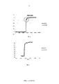
- Figure 4 is a response time curve of an uncorrected liquid crystal display obtained by using S9219 and OPT101 type photodiodes;
- Figure 5 is a graph showing the response time of a corrected liquid crystal display obtained by using S9219 and OPT101 type photodiodes.
- the invention provides a measuring system and a measuring method for measuring the response time of a liquid crystal display.
- the error of the measurement system caused by the use of different actual brightness devices (optical sensors) can be reduced or eliminated.
- FIG. 1 a schematic diagram of a preferred embodiment of a measurement system for response time of a liquid crystal display provided by the present invention is provided.
- the system includes server 1 , standard brightness measuring instrument 3, actual brightness measuring device 4 .
- the standard brightness measuring device 3 and the actual brightness measuring device 4 are electrically connected to the server 1.
- the server 1 is electrically connected to the liquid crystal display.
- the standard brightness measuring instrument 3 is for detecting the brightness of the liquid crystal display to generate a first measured brightness value and reporting it to the server 1.
- the standard brightness measuring instrument 3 can detect the brightness value sensed by the human eye, so the brightness detected by the device in the liquid crystal display industry is the standard brightness value.
- the standard brightness measuring instrument 3 is preferably a CS2000 type brightness analyzer, a CA310 type color degree analyzer, etc., generally obtains a brightness value by measuring a gamma curve, that is, a brightness-gray scale curve, and obtains a standard brightness value thereof.
- the first measured brightness value is converted from the optical signal to a voltage signal and reported to the server 1.
- the standard luminance measuring instrument 3 can only detect changes in luminance with gray scale, and cannot detect changes in luminance with time.
- the actual brightness measuring device 4 For detecting the brightness of the liquid crystal display 2 to generate a second measured brightness value and reporting it to the server 1.
- the actual brightness measuring device 4 is an optical sensor generally used in the liquid crystal display industry, which is a photodiode, which can be reduced. The cost of making a response time measurement system. Of course, it can be other such as CCD (Charge-Coupled Device), PMT (Photo-multiplier Tube) and other types of optical sensors. Different types and different types of optical sensors have inconsistent brightness sensing, and judging whether the sensing of brightness is consistent is to determine whether the brightness values of different types and different types of optical sensors are close to each other by using the brightness value sensed by the human eye as a reference. The brightness value sensed by the human eye.
- the actual brightness measuring device 4 also obtains the second measured brightness value by measuring the gamma curve and converts the second measured brightness value from the optical signal to the voltage signal and reports it to the server 1.
- the actual brightness measuring device 4 is also capable of detecting a change in the second measured brightness value over time and reporting it to the server.
- the server 1 specifically includes a control module 11 that controls display of a preset image on the liquid crystal display.
- the control module 11 preferably provides a specific set of image signals as lighting signals, so that the specific image is displayed on the interface of the liquid crystal display as a measurement object.
- the processing module 12 is configured to acquire the brightness of the liquid crystal display that displays the preset image, and output a brightness-time curve of the brightness that changes with time, specifically including the first processing module 121 and the second processing module 122.
- the first processing module 121 controls the standard brightness meter 3 to detect the brightness of the liquid crystal display, and obtains the first measured brightness value that is detected and reported; the second processing module 122 controls the actual measured brightness value to detect the brightness of the liquid crystal display, and Obtaining the second measured brightness value that is detected and reported, and outputting the second measured brightness value-time curve according to the change of the second measured brightness value detected and reported by the time.
- the correction module 13 is configured to correct the brightness-time curve to obtain a corrected brightness-time curve, and calculate a response time of the liquid crystal display according to the corrected brightness-time curve.
- the data operation module 131 and the data processing module 132 are configured to obtain a matching function by using the first measured brightness value as a dependent variable and the second measured brightness value as an independent variable to obtain a liquid crystal display brightness value, that is, corrected.
- the data processing module 132 is configured to correct the second measured brightness value-time curve by using the corrected liquid crystal display brightness value to obtain a liquid crystal display brightness value-time curve, that is, a corrected second measured brightness value-time curve. And calculating the response time according to the brightness value-time curve of the liquid crystal display.
- the data processing module 14 specifically performs the following operations: acquiring the second measured luminance value-time curve; substituting the liquid crystal display luminance value into the second measured luminance value-time curve to obtain the liquid crystal display luminance value-time a curve; calculating a response time of the liquid crystal display according to the brightness value-time curve of the liquid crystal display.
- FIG. 2 a flow chart of a method for measuring response time of a liquid crystal display provided by the present invention is provided.
- the brightness of the liquid crystal display displaying the preset image is detected by using a standard brightness measuring instrument 3; the brightness of the liquid crystal display displaying the preset image and the brightness are detected by the actual brightness measuring device 4 The change.
- the server 1 acquires the first measured brightness value of the liquid crystal display detected by the standard brightness measuring instrument 3; The second brightness measurement value of the liquid crystal display detected by the actual brightness measuring device 4 and the second measured brightness value-time curve is plotted.
- the display preset image of the liquid crystal display is controlled.
- the preset image is provided by the server 1.
- server 1 The control module 11 provides a specific image for display on the liquid crystal display as a measurement object, providing a brightness signal.
- the brightness value of the liquid crystal display is detected by a standard brightness measuring instrument 3 specified by an industry standard, and the brightness value on the liquid crystal display, that is, the first measured brightness value is obtained by the measured gamma curve, that is, the brightness-gray scale curve, and is reported to server Processing module 12 of 1; using actual brightness measuring device 4 Detecting the brightness value of the liquid crystal display, obtaining the brightness value on the liquid crystal display, that is, the second measured brightness value by the measured gamma curve, that is, the brightness-gray scale curve, and reporting it to the processing 12 of the server 1; using the actual brightness measuring device 4 Detecting the change of the second measured luminance value over time and reporting it to the processing module 12 of the server 1, and the processing module 12 outputs a second measured luminance value-time curve according to the change of the second measured luminance value with time. Since the reported first measured brightness value and the second measured brightness value are both voltage signals, the processing module 12 needs to convert the voltage signals into data signals and send them to the correction module 13.
- the data calculation module 13 in the correction module 13 establishes a second measured brightness value and a first measured brightness value by using the first measured brightness value as a dependent variable y and the second measured brightness value being x.
- the function form can be selected from commonly used mathematical function forms.
- the value of the D constant coefficient to determine the matching function According to the determined matching function, all the second measured brightness values x detected by the actual brightness measuring device 4 can be converted into a first measured brightness value y corresponding thereto, and a corresponding first measured brightness value is established.
- the set is the liquid crystal display brightness value, that is, the corrected second measured brightness value, and the liquid crystal display brightness value is sent to the data processing module 13.
- the data processing module 132 in the correction module replaces the second measured luminance value in the second measured luminance value-time curve with the liquid crystal display luminance value and outputs a new liquid crystal display luminance value-time curve.
- the second measured brightness value corresponding to each x is replaced with the corrected liquid crystal display brightness value by the time value as the x value.
- the time taken to calculate the brightness from 10% to 90% according to the new LCD brightness value-time curve and the time it takes for the brightness to decrease from 90% to 10% is the corrected response time (the method of calculating the response time is the industry).
- the calculation methods specified by the standards are well known to those skilled in the art and will not be described herein.
- the measurement method is further illustrated by way of example.
- the photodiode of the S9219 and OPT101 models is used as the actual brightness measuring device 4 to obtain the gamma curve of the liquid crystal display, and the brightness value is extracted as the second measured brightness value and reported to the server 1.
- the gamma curve of the liquid crystal display is obtained by the standard brightness measuring instrument 3 of the CA310 type, and the brightness value is extracted as the first measured brightness value and reported to the server 1.
- the measured brightness value reported by the S9219 type photodiode is taken as the value of x, and the set of the first measured brightness value y corresponding to one-to-one is calculated according to formula (1) to be the brightness value of the corrected liquid crystal display; the OPT101 type photodiode is reported
- the measured brightness value is taken as the value of x, and a set of the first measured brightness value y corresponding to one-to-one is calculated according to formula (2) as the corrected liquid crystal display brightness value.
- the photodiode and the OPT101 photodiode respectively report the detected measured brightness value to the server 1 with time, and the server 1 replaces the brightness values of the two measured brightness values with the time change curve with the corresponding corrected liquid crystal display respectively.
- the brightness value is plotted as a new liquid crystal display brightness value-time curve as shown in FIG. 5, and the response time detected by the two types of actual brightness measuring devices 4 is substantially the same.
- the uncorrected response time curve is shown in Figure 4, two models The response time detected by the actual brightness measuring device 5 differs by 8 ms.
Landscapes
- Physics & Mathematics (AREA)
- Nonlinear Science (AREA)
- General Physics & Mathematics (AREA)
- Engineering & Computer Science (AREA)
- Chemical & Material Sciences (AREA)
- Crystallography & Structural Chemistry (AREA)
- Optics & Photonics (AREA)
- Computer Hardware Design (AREA)
- Theoretical Computer Science (AREA)
- Control Of Indicators Other Than Cathode Ray Tubes (AREA)
- Testing Of Optical Devices Or Fibers (AREA)
- Testing, Inspecting, Measuring Of Stereoscopic Televisions And Televisions (AREA)
Abstract
一种液晶显示器响应时间的测量方法及系统,该方法包括以下步骤:A、在所述液晶显示器上显示预置图像;B、获取显示所述预置图像的所述液晶显示器的亮度,输出所述亮度随时间变化的亮度-时间曲线;C、对所述亮度-时间曲线进行矫正以获取矫正后的亮度-时间曲线,并根据所述矫正后的亮度-时间曲线计算出所述液晶显示器的响应时间。所述方法有利于减少或消除响应时间测量系统因使用不同的实际亮度测量装置造成测量的响应时间的误差。
Description
本发明涉及液晶显示器特性测量领域,尤其涉及一种液晶显示器响应时间的测量方法及系统。
液晶显示器响应时间指的是液晶显示器各像素点对输入信号反应的速度,即像素由暗转亮或由亮转暗所需要的时间,它是衡量液晶显示器性能的重要参数,直接影响到液晶显示器所显示的图像、特别是动态图像的质量。因此,测量响应时间是液晶显示器性能检测的必需项目。通常来说,对大多数液晶显示器进行响应时间测量时,测量的是由视频电子标准协会(VESA)所管理的305-1标准规定的响应时间,具体为首先预设两个不同的灰度级别(以下称为灰度级别A和灰度级别B),灰度级别的变化对应了液晶显示器亮度的变化。将响应时间定义为初始亮度与目标亮度差的90%的到达时间。然后,测量当液晶显示器显示的图像从灰度级别A变化到灰度级别B时亮度从10%达到90%所用的上升时间Tr,以及液晶显示器显示的图像从灰度级别B变化到灰度级别A时亮度从90%变化到10%所用的下降时间Tf,并将上升时间Tr和下降时间Tf之和记录为液晶显示器的响应时间。
目前,行业中常用的测量响应时间的方法一般是通过实际亮度测量装置(即光学传感器)采集液晶显示器上的动态光学信号,并绘制'亮度-时间'曲线即响应时间曲线。从曲线上找到上升沿(10%-90%)的时间和下降沿(90%-10%)的时间作为响应时间的上升时间和下降时间。
尽管行业内对响应时间有如上明确的定义,但是
液晶显示器行业内相关人员在测量响应时间时所用的实际亮度测量装置是不尽相同的。CCD(Charge-Coupled Device)、Photo
Diode、PMT(Photo-multiplier
Tube)等不同类型、不同型号的实际亮度测量装置都有可能使用在响应时间测量系统中。由于各种实际亮度测量装置存在亮度感应线性度的差异,导致使用不同实际亮度测量装置的响应时间测量系统所的响应时间会不同,进而造成测量的误差。如图4所示,两条曲线分别为OPT101和S9219两种类型的光电二极管测得的192-255灰阶响应时间波形(归一化之后)即亮度随时间变化曲线。由于两条曲线在圆圈标示处的微小差异,导致测量的响应时间数值相差8ms,这在实际使用中已经属于较大的误差了。
本发明的主要目的在于,针对现有技术中存在的因使用不同种类的实际亮度测量装置导致响应时间测量系统测得的响应时间产生差异的缺陷,提出了一种可以对不同种类的实际亮度测量装置的测量数据进行矫正并减小或消除响应时间测量系统因使用不同种类的实际亮度测量装置而导致的测量的误差的液晶显示器响应时间的测量方法及系统。
本发明提供的液晶显示器响应时间的测量方法及系统,其中,该方法包括以下步骤:
A 、控制所述液晶显示器上显示预置的图像;
B 、获取显示所述预置图像的所述液晶显示器的亮度,输出所述亮度随时间变化的亮度-时间曲线;
C
、对所述亮度-时间曲线进行矫正以获取矫正后的亮度-时间曲线,并根据所述矫正后的亮度-时间曲线计算出所述液晶显示器的响应时间。
上述的液晶显示器响应时间的测量方法中,所述步骤B包括:
获取由标准亮度测量仪检测的所述液晶显示器的第一测量亮度值;
获取由实际亮度测量装置检测的所述液晶显示器的第二测量亮度值,根据所述第二测量亮度值随时间的变化输出第二测量亮度值-时间曲线。
上述的液晶显示器响应时间的测量方法中,所述步骤C包括:
C1
、利用所述第一测量亮度值为因变量、所述第二测量亮度值为自变量建立匹配函数,利用所述匹配函数获取液晶显示器亮度值,所述液晶显示器亮度值为矫正后的第二测量亮度值;
C2
、利用所述液晶显示器亮度值矫正所述第二测量亮度值-时间曲线以获取液晶显示器亮度值-时间曲线,并根据所述液晶显示器亮度值-时间曲线计算出所述液晶显示器的响应时间,所述液晶显示器亮度值-时间曲线为矫正后的第二测量亮度值-时间曲线。
上述的液晶显示器响应时间的测量方法中,所述步骤C1包括以下子步骤:
以所述第一测量亮度值为因变量y、所述第二测量亮度值为自变量x,建立所述匹配函数形式y=f(x)=A+Bx+Cx2+Dx3,其中A、B、C、D为常数系数;
利用曲线拟合方式计算所述A、B、C、D常数系数值确定所述匹配函数;
利用所述匹配函数计算得到与所述第二测量亮度值一一对应的第一测量亮度值集合为所述液晶显示器亮度值。
上述的液晶显示器响应时间的测量方法中,所述步骤C2具体为:
获取所述第二测量亮度值-时间曲线;
将所述矫正后的液晶显示器亮度值代入所述第二测量亮度值-时间曲线以获得所述液晶显示器亮度值-时间曲线;
根据所述液晶显示器亮度值-时间曲线计算出所述液晶显示器的响应时间。
一种液晶显示器响应时间的测量系统,包括服务器以及与所述服务器电性连接的标准亮度测量仪、实际亮度测量装置,所述服务器包括用于控制在所述液晶显示器上显示预置图像的控制模块;用于获取显示所述预置图像的所述液晶显示器的亮度,输出所述亮度随时间变化的亮度-时间曲线的处理模块;用于对所述亮度-时间曲线进行矫正以获取矫正后的亮度-时间曲线,并根据所述矫正后的亮度-时间曲线计算出所述液晶显示器的响应时间的矫正模块。
上述的液晶显示器响应时间的测量系统中,所述处理模块还包括:
用于获取由标准亮度测量仪检测的所述液晶显示器的第一测量亮度值的第一处理模块;
用于获取由实际亮度测量装置检测的所述液晶显示器的第二测量亮度值,根据所述第二测量亮度值随时间的变化输出第二测量亮度值-时间曲线的第二处理模块。
上述的液晶显示器响应时间的测量系统中,所述矫正模块还包括:
数据运算模块,用于
根据所述第一测量亮度值为因变量与所述第二测量亮度值为自变量建立匹配函数获取液晶显示器亮度值,所述液晶显示器亮度值为矫正后的第二测量亮度值;
数据处理模块,用于利用所述矫正后的液晶显示器亮度值矫正所述第二测量亮度值-时间曲线以获取液晶显示器亮度值-时间曲线,并根据所述液晶显示器亮度值-时间曲线计算出所述液晶显示器的响应时间,所述液晶显示器亮度值-时间曲线为矫正后的第二测量亮度值-时间曲线
。
上述的液晶显示器响应时间的测量系统中,所述数据运算模块在用于执行根据所述第一测量亮度值为因变量与所述第二测量亮度值为自变量建立匹配函数获取液晶显示器亮度值的操作时,执行以下操作:
以所述第一测量亮度值为因变量y、所述第二测量亮度值为自变量x,建立所述匹配函数形式
y=f(x)=A+Bx+Cx2+Dx3 ,其中A、B、C、D为常数系数;
利用曲线拟合方式计算所述A、B、C、D常数系数值确定所述匹配函数;
利用所述匹配函数计算得到与所述第二测量亮度值一一对应的第一测量亮度值集合为所述液晶显示器亮度值。
上述的液晶显示器响应时间的测量系统中,所述数据处理模块在用于执行利用所述矫正后的液晶显示器亮度值矫正所述第二测量亮度值-时间曲线以获取液晶显示器亮度值-时间曲线,并根据所述液晶显示器亮度值-时间曲线计算出所述液晶显示器的响应时间的操作时,执行以下操作:
获取所述第二测量亮度值-时间曲线;
将所述液晶显示器亮度值代入所述第二测量亮度值-时间曲线以获得所述液晶显示器亮度值-时间曲线;
根据所述液晶显示器亮度值-时间曲线计算出所述液晶显示器的响应时间。
实施本发明的有益效果在于:本发明的方法及系统通过将实际亮度测量装置的测量数据进行矫正,统一使用不同种类实际亮度测量装置的检测数据,从而减小或消除响应时间测量系统因使用不同的实际亮度测量装置造成测量的误差,进而使响应时间测量系统的制作成本降低。
下面将结合附图及实施例对本发明一种液晶显示器响应时间的测量方法及系统作进一步说明,附图中:
图1为本发明提供的一种 液晶显示器响应时间测量系统 的较佳实施例结构框图;
图2为本发明提供的一种液晶显示器响应时间的测量方法的较佳实施例的工作流程图;
图3为图2的详细工作流程图;
图4为利用S9219和OPT101型号光电二极管获取的未经矫正的液晶显示器响应时间曲线;
图5为利用S9219和OPT101型号光电二极管获取的矫正后的液晶显示器响应时间曲线。
本发明提供的一种测量系统和测量方法用于对液晶显示器响应时间进行测量。采用本发明提供的测量系统和测量方法可以减小或消除测量系统因使用不同的实际亮度装置(光学传感器)而导致的测量系统的误差。
参考图1中本发明提供的一种液晶显示器响应时间的测量系统较佳实施例示意图。该系统包括 服务器 1
、标准亮度测量仪3、 实际亮度测量装置 4 。标准亮度测量仪3、实际亮度测量装置4与服务器1电性连接。标准亮度测量仪3、 实际亮度测量装置 4
、服务器1均与液晶显示器电性连接。
标准亮度测量仪3用于检测液晶显示器的亮度以生成第一测量亮度值并将其上报至所述服务器1。标准亮度测量仪3可以检测出人眼感应的亮度值,故在液晶显示器行业中以该设备检测出的亮度为标准亮度值。标准亮度测量仪3较佳为CS2000型的辉度分析仪、CA310型的色彩度分析仪等,一般通过测得伽马曲线即亮度-灰阶曲线来获取亮度值,以其获得的标准亮度值为第一测量亮度值并将该第一测量亮度值从光信号转变成电压信号上报至服务器1。然而标准亮度测量仪3仅能检测到亮度随灰阶的变化,无法检测亮度随时间的变化。
实际亮度测量装置 4
用于检测所述液晶显示器2的亮度以生成第二测量亮度值并将其上报至所述服务器1,实际亮度测量装置4为液晶显示器行业中一般采用的光学传感器,为光电二极管,这可以降低制作响应时间测量系统的成本。当然也可以是其他的如CCD(Charge-Coupled
Device)、PMT(Photo-multiplier
Tube)等不同类型、不同型号的光学传感器。不同类型、不同型号的光学传感器对亮度的感应不一致,而判断其对亮度的感应是否一致就是通过以人眼感应的亮度值为基准,判断不同类型、不同型号的光学传感器感应的亮度值是否接近人眼感应的亮度值。实际亮度测量装置4也通过测定伽马曲线来获得第二测量亮度值并将该第二测量亮度值从光信号转变成电压信号上报至该服务器1。实际亮度测量装置4还能检测第二测量亮度值随时间的变化并将其上报至所述服务器。
服务器1具体包括:控制模块11,控制在所述液晶显示器上显示预置的图像。控制模块11较佳提供一组特定的图像信号作为点亮信号,使液晶显示器的界面上显示该特定的图像作为测量对象。处理模块12用于获取显示所述预置图像的所述液晶显示器的亮度,输出所述亮度随时间变化的亮度-时间曲线,具体包括第一处理模块121和第二处理模块122。第一处理模块121控制标准亮度仪3对液晶显示器的亮度进行检测,并获取其检测并上报的第一测量亮度值;第二处理模块122控制实际测量亮度值对液晶显示器的亮度进行检测,并获取其检测并上报的第二测量亮度值,还根据其检测并上报的第二测量亮度值随时间的变化,输出第二测量亮度值-时间曲线。矫正模块13用于对所述亮度-时间曲线进行矫正以获取矫正后的亮度-时间曲线,并根据所述矫正后的亮度-时间曲线计算出所述液晶显示器的响应时间。具体包括数据运算模块131和数据处理模块132,数据运算模块131以所述第一测量亮度值为因变量、所述第二测量亮度值为自变量建立匹配函数获取液晶显示器亮度值即矫正后的第二测量亮度值。该数据运算模块13具体进行以下操作:以所述第一测量亮度值为因变量y,以所述第二测量亮度值为x,建立所述匹配函数形式y=f(x)=A+Bx+Cx2+Dx3,其中A、B、C、D为常数系数;利用曲线拟合计算所述A、B、C、D常数系数值确定所述匹配函数;利用所述匹配函数得到与所述第二测量亮度值一一对应的第一测量亮度值集合为所述液晶显示器亮度值。数据处理模块132,用于利用所述矫正后的液晶显示器亮度值矫正所述第二测量亮度值-时间曲线以获取液晶显示器亮度值-时间曲线即矫正后的第二测量亮度值-时间曲线,并根据所述液晶显示器亮度值-时间曲线计算出响应时间。该数据处理模块14具体进行以下操作:获取所述第二测量亮度值-时间曲线;将所述液晶显示器亮度值代入所述第二测量亮度值-时间曲线以获得所述液晶显示器亮度值-时间曲线;根据所述液晶显示器亮度值-时间曲线计算出液晶显示器的响应时间。
参考图2中本发明提供的一种液晶显示器响应时间的测量方法的流程图。
A 、控制在所述液晶显示器上显示预置的图像;
B
、获取显示所述预置图像的所述液晶显示器的亮度值,输出所述亮度随时间变化的亮度-时间曲线。具体为:采用标准亮度测量仪3检测显示所述预置图像的所述液晶显示器的亮度;采用实际亮度测量装置4检测显示所述预置图像的所述液晶显示器的亮度以及所述亮度随时间的变化。服务器1获取标准亮度测量仪3检测的所述液晶显示器的第一测量亮度值;获取
实际亮度测量装置 4 检测的所述液晶显示器的第二测量亮度值并绘制所述第二测量亮度值-时间曲线。
C
、对所述亮度-时间曲线进行矫正以获取矫正后的亮度-时间曲线,并根据所述矫正后的亮度-时间曲线计算出液晶显示器的响应时间。
参考图3,进一步详细的说明 本发明提供的一种液晶显示器响应时间的测量方法。
S10
、测量液晶显示器的响应时间时,控制液晶显示器的显示预置的图像。预置的图像由服务器1提供。为取得好的测量效果, 服务器 1
的控制模块11提供特定的图像使其显示在液晶显示器作为测量对象,提供亮度信号。
S20
、采用行业标准规定的标准亮度测量仪3检测上述液晶显示器的亮度值,通过测得的伽马曲线即亮度-灰阶曲线获取液晶显示器上的亮度值即第一测量亮度值并将其上报至 服务器
1 的处理模块12;采用 实际亮度测量装置 4
检测上述液晶显示器的亮度值,通过测得的伽马曲线即亮度-灰阶曲线获取液晶显示器上的亮度值即第二测量亮度值并将其上报至服务器1的处理12;采用实际亮度测量装置4检测第二测量亮度值随时间的变化并将其上报至服务器1的处理模块12,由处理模块12根据第二测量亮度值随时间的变化输出第二测量亮度值-时间曲线。由于上报的第一测量亮度值和第二测量亮度值均为电压信号,处理模块12需将这些电压信号变换为数据信号发送至矫正模块13。
S30 、矫正模块13中的数据计算模块13
以所述第一测量亮度值为因变量y,以所述第二测量亮度值为x,建立了一个表示第二测量亮度值与第一测量亮度值之间关系的匹配函数,所述匹配函数形式选定y=f(x)=A+Bx+Cx2+Dx3,其中A、B、C、D为常数系数;当然匹配函数形式也可以选取y=f(x)=A+Bx+Cx2+Dx3+Ex4等幂次函数或
y=y0+Ae-x/t
等指数函数形式,这里的函数形式可以选取常用的数学函数形式,由于函数形式y=f(x)=A+Bx+Cx2+Dx3已能满足计算要求,则不需要增加更复杂的函数,增加计算难度。所述匹配函数y=f(x)=A+Bx+Cx2+Dx3通过Matlab或Origin等数学分析软件的曲线拟合功能采用常用的最小二乘法拟合曲线计算出了A、B、C、D常数系数的值,从而确定该匹配函数。根据该确定的匹配函数,可以将实际亮度测量装置4检测到的所有第二测量亮度值x对应的换算成与其一一对应的第一测量亮度值y,建立一个对应的第一测量亮度值的集合即液晶显示器亮度值即矫正后的第二测量亮度值,并将液晶显示器亮度值发送至数据处理模块13。
S40
、矫正模块中的数据处理模块132将第二测量亮度值-时间曲线中的第二测量亮度值替换成液晶显示器亮度值并输出新的液晶显示器亮度值-时间曲线。此曲线中,以时间值为x值,将每个x对应的第二测量亮度值替换为矫正后的液晶显示器亮度值。根据新的液晶显示器亮度值-时间曲线计算亮度从10%上升至90%所用的时间以及亮度从90%下降到10%所用的时间即为矫正后的响应时间(该计算响应时间的方法为行业标准规定的计算方法,为本领域技术人员所熟知,在此不作赘述)。
进一步举例说明该测量方法。如采用S9219和OPT101型号的光电二极管作为实际亮度测量装置4分别获取液晶显示器的伽马曲线并提取亮度值作为第二测量亮度值上报至服务器1。采用CA310型的标准亮度测量仪3获取液晶显示器的伽马曲线并提取亮度值作为第一测量亮度值上报至服务器1。服务器1分别建立这两种型号实际亮度测量装置4测得的第二测量亮度值与第一测量亮度值之间的匹配函数,其函数形式均为y=f(x)=A+Bx+Cx2+Dx3,通过Matlab或Origin等数学分析软件的曲线拟合后计算得到两种型号光电二极管的匹配函数分别对应的系数值如下表所示:
| S9219 | OPT101 |
| A=-2.9845 | A=6.19805 |
| B=227.0205 | B=-43.0716 |
| C=665.2955 | C=100.2694 |
| D=-546.917 | D=-16.4014 |
由此,确定S9219型光电二极管对应的匹配函数为:
y=
f(x)=-2.9845+227.0205x+665.2955x2-546.917x3 (1);
确定OPT101型光电二极管对应的匹配函数为:
y=
f(x)=6.19805-43.0716x+100.2694x2-16.4014x3 (2);
将S9219型光电二极管上报的测量亮度值作为x值,根据公式(1)计算其一一对应的第一测量亮度值y的集合以其为矫正后的液晶显示器亮度值;将OPT101型光电二极管上报的测量亮度值作为x值,根据公式(2)计算其一一对应的第一测量亮度值y的集合以其为矫正后的液晶显示器亮度值。
S9219
型光电二极管和OPT101型光电二极管分别将其检测的测量亮度值随时间变化上报至服务器1,服务器1将两种测量亮度值随时间变化曲线中的亮度值分别替换为相应的矫正后的液晶显示器亮度值,绘制出新的液晶显示器亮度值-时间曲线如图5所示,两种型号实际亮度测量装置4检测到的响应时间基本相同。而未经矫正的响应时间曲线如图4所示,两种型号
实际亮度测量装置 5 检测到的响应时间相差8ms。
应当理解的是,对本领域的技术人员来说,可以根据上述说明加以改进或变换,而所有这些改进和变换都应属于本发明所附权利要求的保护范围之内。
Claims (13)
- 一种液晶显示器响应时间的测量方法,其中,包括以下步骤:A 、控制在所述液晶显示器上显示预置的图像;B 、获取显示所述预置图像的所述液晶显示器的亮度,输出所述亮度随时间变化的亮度-时间曲线;C 、对所述亮度-时间曲线进行矫正以获取矫正后的亮度-时间曲线,并根据所述矫正后的亮度-时间曲线计算出所述液晶显示器的响应时间。
- 根据权利要求1所述的液晶显示器响应时间的测量方法,其中,所述步骤B包括:获取由标准亮度测量仪检测的所述液晶显示器的第一测量亮度值;获取由实际亮度测量装置检测的所述液晶显示器的第二测量亮度值,根据所述第二测量亮度值随时间的变化输出第二测量亮度值-时间曲线。
- 根据权利要求2所述的液晶显示器响应时间的测量方法,其中,所述步骤C包括:C1 、利用所述第一测量亮度值为因变量、所述第二测量亮度值为自变量建立匹配函数,利用所述匹配函数获取液晶显示器亮度值,所述液晶显示器亮度值为矫正后的第二测量亮度值;C2 、利用所述液晶显示器亮度值矫正所述第二测量亮度值-时间曲线以获取液晶显示器亮度值-时间曲线,并根据所述液晶显示器亮度值-时间曲线计算出所述液晶显示器的响应时间,所述液晶显示器亮度值-时间曲线为矫正后的第二测量亮度值-时间曲线。
- 根据权利要求3所述的液晶显示器响应时间的测量方法,其中,所述步骤C1包括以下子步骤:以所述第一测量亮度值为因变量y、所述第二测量亮度值为自变量x,建立所述匹配函数形式y=f(x)=A+Bx+Cx2+Dx3,其中A、B、C、D为常数系数;利用曲线拟合方式计算所述A、B、C、D常数系数值确定所述匹配函数;利用所述匹配函数计算得到与所述第二测量亮度值一一对应的第一测量亮度值集合为所述液晶显示器亮度值。
- 根据权利要求4所述的液晶显示器响应时间的测量方法,其中,所述步骤C2具体为:获取所述第二测量亮度值-时间曲线;将所述液晶显示器亮度值代入所述第二测量亮度值-时间曲线以获得所述液晶显示器亮度值-时间曲线;根据所述液晶显示器亮度值-时间曲线计算出所述液晶显示器的响应时间。
- 一种液晶显示器响应时间的测量方法,其中,包括以下步骤:A 、控制在所述液晶显示器上显示预置的图像;B 、获取显示所述预置图像的所述液晶显示器的亮度,输出所述亮度随时间变化的亮度-时间曲线;C 、利用所述第一测量亮度值为因变量、所述第二测量亮度值为自变量建立匹配函数,利用所述匹配函数获取液晶显示器亮度值,所述液晶显示器亮度值为矫正后的第二测量亮度值;D 、利用所述液晶显示器亮度值矫正所述第二测量亮度值-时间曲线以获取液晶显示器亮度值-时间曲线,并根据所述液晶显示器亮度值-时间曲线计算出所述液晶显示器的响应时间,所述液晶显示器亮度值-时间曲线为矫正后的第二测量亮度值-时间曲线。
- 根据权利要求6所述的测量方法,其中,所述步骤C包括以下子步骤:以所述第一测量亮度值为因变量y、所述第二测量亮度值为自变量x,建立所述匹配函数形式y=f(x)=A+Bx+Cx2+Dx3,其中A、B、C、D为常数系数;利用曲线拟合方式计算所述A、B、C、D常数系数值确定所述匹配函数;利用所述匹配函数计算得到与所述第二测量亮度值一一对应的第一测量亮度值集合为所述液晶显示器亮度值。
- 根据权利要求7所述的液晶显示器响应时间的测量方法,其中,所述步骤D具体为:获取所述第二测量亮度值-时间曲线;将所述液晶显示器亮度值代入所述第二测量亮度值-时间曲线以获得所述液晶显示器亮度值-时间曲线;根据所述液晶显示器亮度值-时间曲线计算出所述液晶显示器的响应时间。
- 一种液晶显示器响应时间的测量系统,其中,包括服务器以及与所述服务器电性连接的标准亮度测量仪、 实际亮度测量装置 ,所述服务器包括用于控制在所述液晶显示器上显示预置的图像的控制模块;用于获取显示所述预置图像的所述液晶显示器的亮度,输出所述亮度随时间变化的亮度-时间曲线的处理模块;用于对所述亮度-时间曲线进行矫正以获取矫正后的亮度-时间曲线,并根据所述矫正后的亮度-时间曲线计算出所述液晶显示器的响应时间的矫正模块。
- 根据权利要求9所述的液晶显示器响应时间的测量系统,其中,所述 处理模块还 包括:用于获取由标准亮度测量仪检测的所述液晶显示器的第一测量亮度值的第一处理模块;用于获取由实际亮度测量装置检测的所述液晶显示器的第二测量亮度值,根据所述第二测量亮度值随时间的变化输出第二测量亮度值-时间曲线的第二处理模块。
- 根据权利要求10所述的液晶显示器响应时间的测量系统,其中,所述 矫正模块还 包括:数据运算模块,用于根据所述第一测量亮度值为因变量与所述第二测量亮度值为自变量建立匹配函数获取液晶显示器亮度值,所述液晶显示器亮度值为矫正后的第二测量亮度值;数据处理模块,用于利用所述矫正后的液晶显示器亮度值矫正所述第二测量亮度值-时间曲线以获取液晶显示器亮度值-时间曲线,并根据所述液晶显示器亮度值-时间曲线计算出所述液晶显示器的响应时间,所述液晶显示器亮度值-时间曲线为矫正后的第二测量亮度值-时间曲线。
- 根据权利要求11所述的液晶显示器响应时间的测量系统,其中,所述数据运算模块在用于执行根据所述第一测量亮度值为因变量与所述第二测量亮度值为自变量建立匹配函数获取液晶显示器亮度值的操作时,执行以下操作:以所述第一测量亮度值为因变量y、所述第二测量亮度值为自变量x,建立所述匹配函数形式y=f(x)=A+Bx+Cx2+Dx3,其中A、B、C、D为常数系数;利用曲线拟合方式计算所述A、B、C、D常数系数值确定所述匹配函数;利用所述匹配函数计算得到与所述第二测量亮度值一一对应的第一测量亮度值集合为所述液晶显示器亮度值。
- 根据权利要求12所述的液晶显示器响应时间的测量系统,其中,所述数据处理模块在用于执行利用所述矫正后的液晶显示器亮度值矫正所述第二测量亮度值-时间曲线以获取液晶显示器亮度值-时间曲线,并根据所述液晶显示器亮度值-时间曲线计算出所述液晶显示器的响应时间的操作时,执行以下操作:获取所述第二测量亮度值-时间曲线;将所述液晶显示器亮度值代入所述第二测量亮度值-时间曲线以获得所述液晶显示器亮度值-时间曲线;根据所述液晶显示器亮度值-时间曲线计算出所述液晶显示器的响应时间。
Priority Applications (1)
| Application Number | Priority Date | Filing Date | Title |
|---|---|---|---|
| US14/007,975 US9269287B2 (en) | 2013-03-22 | 2013-06-27 | Method and system for measuring the response time of a liquid crystal display |
Applications Claiming Priority (2)
| Application Number | Priority Date | Filing Date | Title |
|---|---|---|---|
| CN201310096561.1 | 2013-03-22 | ||
| CN201310096561.1A CN103197444B (zh) | 2013-03-22 | 2013-03-22 | 一种液晶显示器响应时间的测量方法及系统 |
Publications (1)
| Publication Number | Publication Date |
|---|---|
| WO2014146373A1 true WO2014146373A1 (zh) | 2014-09-25 |
Family
ID=48720117
Family Applications (1)
| Application Number | Title | Priority Date | Filing Date |
|---|---|---|---|
| PCT/CN2013/078232 Ceased WO2014146373A1 (zh) | 2013-03-22 | 2013-06-27 | 液晶显示器响应时间的测量方法及系统 |
Country Status (2)
| Country | Link |
|---|---|
| CN (1) | CN103197444B (zh) |
| WO (1) | WO2014146373A1 (zh) |
Cited By (2)
| Publication number | Priority date | Publication date | Assignee | Title |
|---|---|---|---|---|
| CN115866343A (zh) * | 2022-12-08 | 2023-03-28 | 四川长虹电器股份有限公司 | 基于图像页面平均亮度比对来测试焦点移动时间的方法 |
| CN115951511A (zh) * | 2023-03-03 | 2023-04-11 | 徐州荣欣网络科技有限公司 | 一种液晶显示器制造测试分析系统 |
Families Citing this family (6)
| Publication number | Priority date | Publication date | Assignee | Title |
|---|---|---|---|---|
| CN106679933B (zh) * | 2016-11-21 | 2020-03-10 | 福建省华渔教育科技有限公司 | 一种头显设备性能测试方法及系统 |
| CN107423212B (zh) * | 2017-03-17 | 2020-12-01 | 深圳普瑞赛思检测技术有限公司 | 虚拟现实设备屏幕响应延时的测评方法及装置 |
| CN108447456B (zh) * | 2018-02-28 | 2019-11-05 | 北京德为智慧科技有限公司 | 一种影像显示校正方法及装置 |
| CN110596483A (zh) * | 2019-08-02 | 2019-12-20 | 惠州市德赛西威汽车电子股份有限公司 | 一种仪表响应时间的自动化测试系统及方法 |
| CN114114725B (zh) * | 2020-08-28 | 2024-11-15 | 深圳莱宝高科技股份有限公司 | 一种测试lcm响应时间的方法及相关设备 |
| CN116819811B (zh) * | 2023-07-18 | 2024-06-07 | 深圳市晟君安科技有限公司 | 一种液晶显示器响应时间的测量方法和系统 |
Citations (5)
| Publication number | Priority date | Publication date | Assignee | Title |
|---|---|---|---|---|
| CN1673810A (zh) * | 2005-04-19 | 2005-09-28 | 浙江大学 | 液晶显示器响应时间光电自动测量仪 |
| US7164284B2 (en) * | 2003-12-18 | 2007-01-16 | Sharp Laboratories Of America, Inc. | Dynamic gamma for a liquid crystal display |
| CN101211035A (zh) * | 2006-12-29 | 2008-07-02 | 群康科技(深圳)有限公司 | 液晶显示器伽马校正系统与校正方法 |
| CN101806656A (zh) * | 2010-03-08 | 2010-08-18 | 东南大学 | 笔记本电脑液晶显示屏亮度响应特性测量仪 |
| CN102682681A (zh) * | 2011-03-18 | 2012-09-19 | 青岛海信电器股份有限公司 | 液晶屏响应时间测量方法及装置 |
-
2013
- 2013-03-22 CN CN201310096561.1A patent/CN103197444B/zh not_active Expired - Fee Related
- 2013-06-27 WO PCT/CN2013/078232 patent/WO2014146373A1/zh not_active Ceased
Patent Citations (5)
| Publication number | Priority date | Publication date | Assignee | Title |
|---|---|---|---|---|
| US7164284B2 (en) * | 2003-12-18 | 2007-01-16 | Sharp Laboratories Of America, Inc. | Dynamic gamma for a liquid crystal display |
| CN1673810A (zh) * | 2005-04-19 | 2005-09-28 | 浙江大学 | 液晶显示器响应时间光电自动测量仪 |
| CN101211035A (zh) * | 2006-12-29 | 2008-07-02 | 群康科技(深圳)有限公司 | 液晶显示器伽马校正系统与校正方法 |
| CN101806656A (zh) * | 2010-03-08 | 2010-08-18 | 东南大学 | 笔记本电脑液晶显示屏亮度响应特性测量仪 |
| CN102682681A (zh) * | 2011-03-18 | 2012-09-19 | 青岛海信电器股份有限公司 | 液晶屏响应时间测量方法及装置 |
Cited By (4)
| Publication number | Priority date | Publication date | Assignee | Title |
|---|---|---|---|---|
| CN115866343A (zh) * | 2022-12-08 | 2023-03-28 | 四川长虹电器股份有限公司 | 基于图像页面平均亮度比对来测试焦点移动时间的方法 |
| CN115866343B (zh) * | 2022-12-08 | 2024-03-12 | 四川长虹电器股份有限公司 | 基于图像页面平均亮度比对来测试焦点移动时间的方法 |
| CN115951511A (zh) * | 2023-03-03 | 2023-04-11 | 徐州荣欣网络科技有限公司 | 一种液晶显示器制造测试分析系统 |
| CN115951511B (zh) * | 2023-03-03 | 2023-06-20 | 徐州荣欣网络科技有限公司 | 一种液晶显示器制造测试分析系统 |
Also Published As
| Publication number | Publication date |
|---|---|
| CN103197444A (zh) | 2013-07-10 |
| CN103197444B (zh) | 2015-09-30 |
Similar Documents
| Publication | Publication Date | Title |
|---|---|---|
| WO2014146373A1 (zh) | 液晶显示器响应时间的测量方法及系统 | |
| US11527201B2 (en) | Display panel with photosensors for pixel calibration and method of driving display panel therewith | |
| CN107507571B (zh) | 一种对amoled进行外部光学补偿的方法及装置 | |
| CN101806627A (zh) | 一种背景因素对红外测温影响的测量方法 | |
| TW201903750A (zh) | 應用於顯示面板之光學補償裝置及其運作方法 | |
| CN109525840B (zh) | 一种成像芯片上微弱缺陷的检测方法 | |
| WO2013127092A1 (zh) | 一种斜视角图像的模拟方法及装置 | |
| US20180293945A1 (en) | Driving system of display screen and driving method thereof | |
| CN101621699A (zh) | 一种视频显示不均匀校正方法及投影装置 | |
| US10750148B2 (en) | Unevenness correction system, unevenness correction apparatus and panel drive circuit | |
| CN103761945A (zh) | 一种TFT-LCD液晶屏的Gamma曲线调整方法及调整装置 | |
| TW201546781A (zh) | 影像分析和影像顯示的裝置和方法 | |
| WO2013127093A1 (zh) | 一种斜视角图像的模拟方法及装置 | |
| CN110710195B (zh) | 图像显示装置及其控制方法 | |
| CN116819811B (zh) | 一种液晶显示器响应时间的测量方法和系统 | |
| US9269287B2 (en) | Method and system for measuring the response time of a liquid crystal display | |
| CN108206014B (zh) | 液晶显示面板的显示方法及液晶显示装置 | |
| JP2006266750A (ja) | 欠陥検査方法および欠陥検査装置 | |
| CN101435693B (zh) | 影像测量机台光源校正系统及方法 | |
| CN115914592A (zh) | 一种扫描器驱动方法、可读存储介质及装置 | |
| CN115574952B (zh) | 一种液晶显示屏实时温度检测装置及其控制方法 | |
| CN115144010A (zh) | 图像传感器非均匀性与非线性度同步标定与校正方法 | |
| CN208907961U (zh) | 一种摄像装置成像延时时间的测量装置 | |
| JP2008102818A (ja) | 撮像手段の出力値補正方法、シェーディング補正方法、欠陥検出方法、欠陥検出プログラムおよび欠陥検出装置 | |
| EP4379312B1 (en) | System and method for handling a thermal compensation |
Legal Events
| Date | Code | Title | Description |
|---|---|---|---|
| WWE | Wipo information: entry into national phase |
Ref document number: 14007975 Country of ref document: US |
|
| 121 | Ep: the epo has been informed by wipo that ep was designated in this application |
Ref document number: 13878645 Country of ref document: EP Kind code of ref document: A1 |
|
| NENP | Non-entry into the national phase |
Ref country code: DE |
|
| 122 | Ep: pct application non-entry in european phase |
Ref document number: 13878645 Country of ref document: EP Kind code of ref document: A1 |