WO2014142176A1 - 微生物腐食防止方法及びカソード防食方法 - Google Patents
微生物腐食防止方法及びカソード防食方法 Download PDFInfo
- Publication number
- WO2014142176A1 WO2014142176A1 PCT/JP2014/056513 JP2014056513W WO2014142176A1 WO 2014142176 A1 WO2014142176 A1 WO 2014142176A1 JP 2014056513 W JP2014056513 W JP 2014056513W WO 2014142176 A1 WO2014142176 A1 WO 2014142176A1
- Authority
- WO
- WIPO (PCT)
- Prior art keywords
- metal material
- window region
- electrode
- negative voltage
- potential window
- Prior art date
- Legal status (The legal status is an assumption and is not a legal conclusion. Google has not performed a legal analysis and makes no representation as to the accuracy of the status listed.)
- Ceased
Links
Images



Classifications
-
- C—CHEMISTRY; METALLURGY
- C23—COATING METALLIC MATERIAL; COATING MATERIAL WITH METALLIC MATERIAL; CHEMICAL SURFACE TREATMENT; DIFFUSION TREATMENT OF METALLIC MATERIAL; COATING BY VACUUM EVAPORATION, BY SPUTTERING, BY ION IMPLANTATION OR BY CHEMICAL VAPOUR DEPOSITION, IN GENERAL; INHIBITING CORROSION OF METALLIC MATERIAL OR INCRUSTATION IN GENERAL
- C23F—NON-MECHANICAL REMOVAL OF METALLIC MATERIAL FROM SURFACE; INHIBITING CORROSION OF METALLIC MATERIAL OR INCRUSTATION IN GENERAL; MULTI-STEP PROCESSES FOR SURFACE TREATMENT OF METALLIC MATERIAL INVOLVING AT LEAST ONE PROCESS PROVIDED FOR IN CLASS C23 AND AT LEAST ONE PROCESS COVERED BY SUBCLASS C21D OR C22F OR CLASS C25
- C23F13/00—Inhibiting corrosion of metals by anodic or cathodic protection
-
- C—CHEMISTRY; METALLURGY
- C23—COATING METALLIC MATERIAL; COATING MATERIAL WITH METALLIC MATERIAL; CHEMICAL SURFACE TREATMENT; DIFFUSION TREATMENT OF METALLIC MATERIAL; COATING BY VACUUM EVAPORATION, BY SPUTTERING, BY ION IMPLANTATION OR BY CHEMICAL VAPOUR DEPOSITION, IN GENERAL; INHIBITING CORROSION OF METALLIC MATERIAL OR INCRUSTATION IN GENERAL
- C23F—NON-MECHANICAL REMOVAL OF METALLIC MATERIAL FROM SURFACE; INHIBITING CORROSION OF METALLIC MATERIAL OR INCRUSTATION IN GENERAL; MULTI-STEP PROCESSES FOR SURFACE TREATMENT OF METALLIC MATERIAL INVOLVING AT LEAST ONE PROCESS PROVIDED FOR IN CLASS C23 AND AT LEAST ONE PROCESS COVERED BY SUBCLASS C21D OR C22F OR CLASS C25
- C23F2213/00—Aspects of inhibiting corrosion of metals by anodic or cathodic protection
- C23F2213/30—Anodic or cathodic protection specially adapted for a specific object
- C23F2213/31—Immersed structures, e.g. submarine structures
Definitions
- JP2013-052725 application number filed in Japan on March 15, 2013.
- the contents described in JP2013-052725 are incorporated into the present application.
- the present invention relates to a method for preventing microbial corrosion and a method for preventing cathodic corrosion, for example, to a method for preventing microbial corrosion of a metal material arranged in an environment such as water containing microorganisms or soil containing moisture containing microorganisms.
- microbial corrosion is a phenomenon in which the metal surface potential becomes noble and corrodes with the activity of microorganisms attached to the metal surface.
- the most effective method against this microbial corrosion is to kill the microorganisms by some means.
- a sterilizing treatment is performed by injecting a bactericide, or a bacteriostatic agent is injected to suppress the activity of the microorganism.
- a sterilizing treatment is performed by injecting a bactericide, or a bacteriostatic agent is injected to suppress the activity of the microorganism.
- this method is not preferable because the effects of the bactericide and the bacteriostatic agent differ depending on the type of microorganisms, and the prevention of microbial corrosion due to the injection of the chemical causes water pollution.
- cathodic protection is a method in which a negative potential is applied to a metal material to prevent the potential of the metal surface from becoming noble (see, for example, Patent Document 1).
- ISO International Organization for Standardization
- vs SCE Kankan electrode standard
- .10V vs SCE
- the usefulness of the recommended potential in an anaerobic environment is not as clear as in an aerobic environment.
- any negative potential is effective as a countermeasure against carbon dioxide (sweet corrosion) and hydrogen sulfide (sour corrosion) contained in oil and gas fields, it cannot be said to be sufficient for microbial corrosion. It is known that the antimicrobial effect is exhibited for a while after the start of anticorrosion, but the microorganisms proliferate if the anticorrosion is continued for a long time.
- the current on the metal surface is kept flowing to prevent the potential of the metal surface from becoming noble, so that the necessary anticorrosion current gradually increases with the growth of microorganisms. Therefore, if corrosion prevention is continued for a long period of time, the maximum output current value of the constant potential DC power supply device will eventually be exceeded. As a result, it has been found that the anticorrosion current is insufficient, deviates from the potential setting value, the potential shifts noblely, and the anticorrosion control potential cannot be maintained.
- the conventional cathodic protection method described above constantly discharges hydrogen from the surface of the metal material in order to constantly pass an electric current, which may cause an explosion when touched by fire, peeling of the coating of the metal material, or hydrogen embrittlement. There was a problem of fear. Furthermore, since it is necessary to keep a current flowing, there is a problem that electric energy consumed is enormous. In other words, in the conventional anti-corrosion (cathodic protection), since the current for preventing the metal material is kept flowing for a long period of time, the power cost is increased and the energy is continuously consumed. For this reason, a technique for reducing the amount of current required for preventing microbial corrosion over a long period of time is desired.
- an object of the present invention is to overcome the above-mentioned problems and to provide a method for preventing microbial corrosion that can significantly reduce the amount of current required for corrosion prevention.
- the method for preventing microbial corrosion of one embodiment of the present invention includes: A method for preventing microbial corrosion, which prevents microbial corrosion of a metal material disposed in one environment of water containing microorganisms and soil containing water containing microorganisms, Applying a negative voltage in the potential window region where current does not flow substantially depending on the type of metal material, to the metal material placed in one environment of the water containing microorganisms and the soil containing water containing microorganisms It is characterized by.
- the cathodic protection method of one embodiment of the present invention includes: An anode electrode is placed in one environment in the water where microorganisms are present and in the soil containing moisture where microorganisms are present, A metal material disposed in the environment is used as a cathode electrode, and a negative voltage in a potential window region where no current substantially flows between the anode electrode and the cathode electrode is applied to the metal material.
- the amount of current required to prevent microbial corrosion can be significantly reduced.
- FIG. 3 is a flowchart showing main steps of the microbial corrosion prevention method according to Embodiment 1.
- 3 is a graph showing a polarization curve of carbon steel in the first embodiment.
- 1 is a diagram showing a configuration of an experimental apparatus according to Embodiment 1.
- FIG. 3 is a diagram showing the composition of the medium of the first embodiment. 3 is a graph showing a relationship between corrosion current and time obtained as an experimental result in the first embodiment.
- the conventional cathodic protection method continues to supply electrons from the metal surface in order to prevent the potential of the metal surface from becoming noble by constantly passing an electric current.
- Microorganisms involved in corrosion are donated with electrons from metal materials and live and multiply. Therefore, although microorganisms have a temporary effect of preventing microbial corrosion, the microorganisms proliferate over a long period of time. Therefore, in the conventional anticorrosion technique by applying a negative potential, it is known that the antimicrobial effect is exhibited for a while after the anticorrosion is started, but the microorganism grows if the anticorrosion is continued for a long time.
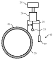
- FIG. 1 is a conceptual diagram showing an example of the device configuration of the anticorrosion system in the first embodiment.
- water in which microorganisms are present is accumulated inside a metal pipe 20 (an example of a cathode and a working electrode). Alternatively, it may flow.
- a metal pipe 20 an example of a cathode and a working electrode.
- it is the underwater environment 40 in which microorganisms exist inside the pipe.
- the environment 40 is not limited to this, and may be, for example, a soil environment including moisture in which microorganisms exist.
- the pipe 20 has the inner surface 34 (inner surface) disposed in one environment 40 in water containing microorganisms and soil containing moisture containing microorganisms.
- the type of microorganism is not particularly limited, but can be applied to any of sulfate-reducing bacteria, methanogenic archaea, iodine-oxidizing bacteria, iron-oxidizing bacteria, iron-reducing bacteria, and the like.
- sulfate-reducing bacteria include Desulfobrio desulfuricans, Desuloviobrio vulgaris, Desuluromonas acetoxidans, Desuluromonas svalbardensis strain 112, Desulfobium strains 112, Desulfobium.
- sulfur-oxidizing bacteria examples include Acidithiobacillus thiooxidans, Sulfurimonas autotrophica, and the like.
- methanogenic archaea examples include Methanobacterium bryantii or Methanobacterium thermoautotrophicum.
- Examples of the iodine-oxidizing bacteria include Rhodothalassium salexigens and Roseovarius tolerans.
- Examples of iron-oxidizing bacteria include Acidithiobacillus ferrooxidans and the like.
- Examples of iron-reducing bacteria include Shewanella oneidensis or Geobacter sulfur reductions.
- Examples of the environment in water in which microorganisms exist and in soil containing moisture in which microorganisms exist include, for example, oil fields, gas fields, soils, seabeds (underwater), and the like. Therefore, as metal materials, pipes, heat exchangers, oil tanks, ship outer walls, harbor facilities, subsurface structures, marine structures, etc. arranged in at least one of oil fields, gas fields, soil and seabed Is suitable as a target.
- a counter electrode 22 (an example of an anode electrode) is disposed in the pipe 20, for example, in an underwater environment where microorganisms exist.
- the reference electrode 24 is further arrange
- the counter electrode 22, the reference electrode 24, and the pipe 20 (working electrode) are connected to the potentiostat 26.
- a potential sweeper 28 is connected to the potentiostat 26.
- the first embodiment includes a three-electrode system circuit including the pipe 20 (working electrode), the counter electrode 22, and the reference electrode 24.
- FIG. 2 is a conceptual diagram showing another example of the device configuration of the anticorrosion system in the first embodiment.
- water containing microorganisms is accumulated outside the metal pipe 20 (an example of a cathode and a working electrode).
- the pipe 20 is arranged in one environment 40 in which the outer surface 35 (outer surface) includes water in which microorganisms exist and soil containing moisture in which microorganisms exist.
- the counter electrode 22 an example of an anode electrode
- the reference electrode 24 is further arrange
- Other configurations are the same as those in FIG.
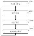
- FIG. 3 is a flowchart showing the main steps of the microbial corrosion prevention method according to the first embodiment.
- the microbial corrosion prevention method (cathode anticorrosion method) in Embodiment 1 includes a potential window measurement step (S102), a voltage application step (S104), a potential holding step (S106), and an electric circuit opening step ( A series of steps of S108) is performed.
- a potential window region of a metal material to be protected against corrosion is measured.
- the potential window region indicates a negative voltage range where substantially no current flows depending on the type of the metal material.
- substantially no current flows means that the current density is 0 to 30 ⁇ Acm ⁇ 2 .
- a range of 0 to 10 ⁇ Acm ⁇ 2 is preferable. More preferably, it is 0 to 1 ⁇ Acm ⁇ 2 .
- FIG. 4 is a graph showing a polarization curve of the carbon steel in the first embodiment.
- the ISO (International Organization for Standardization) standard recommends ⁇ 0.6 to ⁇ 0.9 V (vsSHE: hydrogen electrode reference conversion) as a negative potential for carbon steel in an aerobic environment.
- vsSHE hydrogen electrode reference conversion
- vsSHE conversion is recommended as a negative potential to be applied.
- the usefulness of the recommended potential in an anaerobic environment is not as clear as in an aerobic environment.
- Embodiment 1 when a current density region of 30 ⁇ Acm ⁇ 2 or less is defined as a potential window, the negative voltage range (potential window region) in which carbon steel does not substantially flow current is ⁇ This corresponds to 420 to ⁇ 610 mV (vsSHE: hydrogen electrode standard).
- a case is shown in which simulated seawater having a pH of 7.6 is used as the medium for measuring the potential window. Except for the carbon steel described above, under the same conditions, the potential window region is as follows, for example.
- the potential window measurement step (S102) may be omitted if it is known in advance.
- a negative voltage in the potential window region where no current substantially flows according to the type of the metal material is applied to the pipe 20 (metal material).
- a voltage of ⁇ 420 to ⁇ 610 mV (vs SHE) is applied.
- a voltage of ⁇ 500 to ⁇ 600 mV (vs SHE) is more preferable.
- a voltage of ⁇ 500 to ⁇ 530 mV (vs SHE) is good.
- a voltage of ⁇ 500 mV (vs SHE) is applied.
- the application of the negative voltage in the potential window region to the pipe 20 is held for a predetermined period.
- the potential of the metal pipe 20 is precisely controlled. Therefore, it is preferable that the negative potential in the potential window region is controlled by a three-electrode system circuit including the pipe 20 (working electrode), the reference electrode 24, and the counter electrode 22.
- the potential can be held with higher accuracy than when the potential is controlled by a two-electrode circuit of an anode (anode) and a negative electrode (cathode).
- the case of controlling the potential with a two-electrode system circuit is not excluded.
- the potential of the pipe 20 (working electrode) is controlled by the potentiostat 26 and the potential sweeper 28 so as to keep constant with respect to the reference electrode 24 in an underwater environment where microorganisms survive.
- the pipe 20 (working electrode) since the potential (voltage 30) of the pipe 20 (working electrode) is set with respect to the reference electrode 24, the pipe 20 (working electrode) from, for example, the counter electrode 22 (anode) in an underwater environment where microorganisms survive. : Substantially no current flows to the cathode). What is necessary is just to set suitably about the period to hold
- Embodiment 1 since no current flows through the pipe 20, the supply of electrons to the microorganisms can be substantially eliminated. Therefore, it becomes difficult for microorganisms to survive on the surface of the pipe 20. Therefore, microorganisms can be killed (can be removed) or separated at the interface between the pipe 20 and the underwater environment where microorganisms are present. Furthermore, adhesion of new microorganisms can be prevented. Therefore, microbial corrosion of the pipe 20 can be prevented. Furthermore, in the first embodiment, since current is not substantially passed, generation of hydrogen from the surface of the metal material can be prevented. Therefore, problems such as the possibility of hydrogen exploding upon contact with fire, peeling of the coating of the metal material, and hydrogen embrittlement can be avoided.
- the consumed electric energy can be greatly reduced. Therefore, the power cost can be greatly reduced and the energy consumption can be greatly reduced. For this reason, it is particularly effective when performing corrosion prevention of microbial corrosion over a long period of time.
- the negative voltage application in the potential window region is released.
- Microorganisms adhering to the pipe 20 (metal material) while the negative voltage in the potential window region is not applied can be killed (can be disinfected) or detached by applying the negative voltage in the potential window region again. Thereby, electrode consumption can be further reduced.
- a current of about 200 ⁇ Acm ⁇ 2 to 2 mAcm ⁇ 2 is generated “steadyly”.
- Embodiment 1 a sufficient anticorrosion effect can be obtained by “intermittent” potential application, so that energy reduction and hydrogen generation can be suppressed.
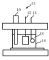
- FIG. 5 is a diagram showing a configuration of the experimental apparatus according to the first embodiment.
- an iron plate electrode is used as the working electrode 12, a silver-silver chloride electrode as the reference electrode 10, and a platinum wire as the counter electrode 14 in the electrochemical cell 11 having a total capacity of 8 mL.
- the three electrodes are immersed in a glass container 16 containing the culture medium 18. Moreover, these three electrodes are connected to an external electrochemical measurement system.
- As a medium 18, 4 mL of Marine Broth (composition will be described later) is added to the electrochemical cell 16 to form a closed system, and an anaerobic state is established by bubbling with nitrogen for 10 minutes or more using an injection needle.
- the iron plate portion of the iron plate electrode is completely immersed in the solution.
- the electrochemical cell 11 is assembled in a clean bench after all UV (ultraviolet) sterilization or alcohol sterilization is performed.
- the system is brought to a low temperature of 25 ° C. by connecting a circulating thermostat to the jacket and flowing warm water.
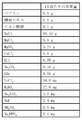
- FIG. 6 is a diagram showing the composition of the medium of the first embodiment.
- Marine Broth serving as the culture medium 18
- peptone 5.0 g
- yeast extract 1.0 g
- iron citrate 0.1 g
- NaCl (19. 45 g)
- MgCl 2 5.9 g
- MgSO 4 3.24 g
- CaCl 2 1.8 g
- KCl 0.55 g
- Na 2 CO 3 (0.16 g
- KBr (0.08 g)
- SrCl 2 (34.0 mg)
- H 3 BO 3 (22.0 mg
- Na 2 SiO 3 4.0 mg
- NaF 2.4 mg
- NH 4 NO 3 1.6 mg
- Na 2 The one containing HPO 4 (8.0 mg) was used.
- the iron plate electrode is made using carbon steel pieces.
- a carbon steel piece (20 ⁇ 10 ⁇ 5 mm, 15 ⁇ 10 ⁇ 0.5 mm, etc.) is polished with a # 1000 or more file and then a titanium wire is connected using a silver paste, and the connecting portion is covered with epoxy. Solidify. After the epoxy is completely hardened, the iron plate surface is polished again using a file of # 1000 or more. To keep the system sterilized, place the iron plate electrode under UV before use and sterilize.
- samples collected from the accumulated water in crude oil storage tanks set in Saudi Arabia are used (samples are stored at 4 ° C under anaerobic conditions, sampled solutions are stored under microaerobic conditions, 4 The one stored at °C and the one planted in Marine Broth anaerobic medium were prepared and used for the experiment).
- samples collected from the accumulated water in crude oil storage tanks set in Saudi Arabia are used (samples are stored at 4 ° C under anaerobic conditions, sampled solutions are stored under microaerobic conditions, 4 The one stored at °C and the one planted in Marine Broth anaerobic medium were prepared and used for the experiment).
- 40 mL of stock water in a stock solution is centrifuged at 13,000 rpm for 10 minutes at 4 ° C., and the supernatant is discarded.
- centrifuge 400 ⁇ L to 4 mL of sample at 13,000 rpm for 10 minutes at 4 ° C. with respect to one electrochemical cell discard the supernatant, and leave Marine here About 4 mL of Broth was added and pipetted, centrifuged again at 13,000 rpm for 10 minutes at 4 ° C., 3.8 mL of the supernatant was discarded, and the remaining 200 ⁇ L was suspended and added to the electrochemical cell.
- pre-culture under potential control was performed for one week.
- Four electrochemical cells were prepared, and the working electrode 12 was held at a constant potential of ⁇ 800 mV (vs SHE), ⁇ 600 mV (vs SHE), ⁇ 500 mV (vs SHE), and ⁇ 400 mV (vs SHE).
- potential control of carbon steel is made possible by connecting to a potentiostat and a potential sweeper.
- the bacterial cell concentrate was added thereto, and precultured for one week.
- a preculture sample without potential control was prepared.
- FIG. 7 is a graph showing the relationship between corrosion current and time obtained as an experimental result in the first embodiment.
- samples of ⁇ 800 mV (vs SHE), ⁇ 600 mV (vs SHE), ⁇ 500 mV (vs SHE), and ⁇ 400 mV (vs SHE) are represented as S ( ⁇ 800), S ( ⁇ 600), S ( ⁇ 500), This is indicated by S (no application).
- S (no application) a sample containing no cells was prepared, and the corrosion rate was estimated by the polarization resistance method. In FIG. 7, this sample is indicated by S (no cells).
- FIG. 7 the time change of the corrosion current in various samples is shown. It can be seen that the corrosion current value increased with time in the sample to which no potential application was performed (S (no application)).
- S (no cells) since no increase in corrosion current was observed in the sample containing no cells (S (no cells)), the increase in current observed in S (no application) was caused by microorganisms.
- the corrosion current was significantly suppressed as compared with S (no application) (about 90%). %) And a corrosion current value similar to that of S (no cells).
- the result coincides with the fact that it is more preferable to apply a voltage of ⁇ 500 to ⁇ 600 mV (vs SHE). More preferably, the result agrees with the fact that it is good to apply a voltage of ⁇ 500 to ⁇ 530 mV (vs. SHE).
- the present invention relates to a method for preventing microbial corrosion and a method for preventing cathodic corrosion.
- it can be used as a method for preventing microbial corrosion of a metal material arranged in an environment such as water containing microorganisms or soil containing water containing microorganisms.
Landscapes
- Chemical & Material Sciences (AREA)
- Engineering & Computer Science (AREA)
- Materials Engineering (AREA)
- Mechanical Engineering (AREA)
- Metallurgy (AREA)
- Organic Chemistry (AREA)
- Prevention Of Electric Corrosion (AREA)
Abstract
本発明の一態様の微生物腐食防止方法は、微生物が存在する水中及び微生物が存在する水分を含む土壌中の一方の環境に配置された金属材料の微生物腐食を防止する微生物腐食防止方法であって、微生物が存在する水中及び微生物が存在する水分を含む土壌中の一方の環境に配置された金属材料に、金属材料の種類に応じた実質的に電流が流れない電位窓領域の負の電圧を印加することを特徴する。
Description
本出願は、2013年3月15に日本国に出願されたJP2013-052725(出願番号)を基礎出願とする優先権を主張する出願である。JP2013-052725に記載された内容は、本出願にインコーポレートされる。
本発明は、微生物腐食防止方法及びカソード防食方法に係り、例えば、微生物が存在する水中或いは微生物が存在する水分を含む土壌中といった環境中に配置された金属材料の微生物腐食を防止する手法に関する。
金属材料の防食技術については、例えば、油田・ガス田での例として、耐食性材質の使用、塗料等の塗布による被覆、腐食抑制剤(インヒビター)の添加、金属材料の電位の貴化を抑制する電気防食などの方法を採用し、腐食の程度を減じる対策が行われている。しかしながら、近年報告されている微生物腐食に対する対策としては充分ではない。
かかる微生物腐食は、金属表面に付着した微生物の活動に伴い、金属表面電位が貴化して腐食する現象であることは広く知られている。この微生物腐食に対して最も有効な方法は、その微生物を何らかの手段で死滅させることであり、従来技術では殺菌剤を注入して殺菌処理したり、静菌剤を注入して微生物の活動を抑制したりして、微生物腐食を防止している。しかしながら、この方法は微生物の種類によって殺菌剤および静菌剤の効果が異なるために充分な効果が得られず、また薬剤注入による微生物腐食防止は、水質汚染をもたらすため好ましくない。
また、総合的な腐食対策として、電気防食(カソード防食)法が採用されることが多い。この電気防食法は、金属材料に負の電位を印加し、金属表面の電位の貴化を防止する方法である(例えば、特許文献1参照)。また、ISO(国際標準化機構)規格では、炭素鋼について、好気環境において、-0.80~-1.10V(vsSCE:かん甘電極基準)が、嫌気環境では、-0.9~-1.10V(vsSCE)が印加する負の電位として推奨されている。但し、かかるISO基準において、嫌気環境での推奨されている電位の有用性は好気環境にようには明らかになっていない。
いずれの負電位についても、油田・ガス田に含まれる二酸化炭素(スイート腐食)・硫化水素(サワー腐食)に対する対策としては有効なものの、微生物腐食に対しては十分とは言えない。これは、防食を開始してしばらくの期間は微生物腐食防止効果が発揮されるものの、長期間電気防食を続けていると微生物が増殖することがわかっている。上述した従来の電気防食法は、常に電流を流し続けることで金属表面の電位の貴化を防止するため、微生物の増殖に伴い、必要となる防食電流が徐々に増加してしまう。そのため、長期にわたり防食を続けていると、最終的に定電位直流電源装置の最大出力電流値を超えてしまう。その結果、防食電流が不足し、電位設定値から外れて、電位が貴に移行して防食管理電位を維持できないことがわかっている。
さらに、上述した従来の電気防食法は、常に電流を流すために、金属材料の表面から常時水素を出し続けることになり、火気に触れて爆発する恐れや金属材料のコーティングのはく離や水素脆化の恐れがあるといった問題があった。さらに、電流を流し続ける必要があるため、消費される電気エネルギーも膨大であるといった問題があった。言い換えれば、従来技術の電気防食(カソード防食)では、長期にわたり金属材料を防食するための電流を流し続けるために、電力コストがかかり、かつエネルギーを消費し続けることになる。このために、長期にわたり、微生物腐食の防食に要する電流量を低減する技術が望まれている。
ここで、例えばパイプラインや下水道管などの嫌気性の特殊な環境では、硫酸還元細菌による微生物腐食の危険性が指摘されており、具体的には英国のパイプライン腐食,米国の下水管腐食では“少なくとも50%”は硫酸還元細菌による微生物腐食によるという報告もあり、従来技術の電気防食(カソード防食)の改善が求められている。
上述の通り、従来、金属材料の微生物腐食を防止するために各種の方法が提案されているが、いずれも微生物腐食を効果的に防止するには十分とは言えない状況にある。
そこで、本発明は、上述した問題点を克服し、防食に要する電流量が著しく低減可能な微生物腐食の防止手法を提供することを目的とする。
本発明の一態様の微生物腐食防止方法は、
微生物が存在する水中及び微生物が存在する水分を含む土壌中の一方の環境に配置された金属材料の微生物腐食を防止する微生物腐食防止方法であって、
微生物が存在する水中及び微生物が存在する水分を含む土壌中の一方の環境に配置された金属材料に、金属材料の種類に応じた実質的に電流が流れない電位窓領域の負の電圧を印加することを特徴する。
微生物が存在する水中及び微生物が存在する水分を含む土壌中の一方の環境に配置された金属材料の微生物腐食を防止する微生物腐食防止方法であって、
微生物が存在する水中及び微生物が存在する水分を含む土壌中の一方の環境に配置された金属材料に、金属材料の種類に応じた実質的に電流が流れない電位窓領域の負の電圧を印加することを特徴する。
本発明の一態様のカソード防食方法は、
微生物が存在する水中及び微生物が存在する水分を含む土壌中の一方の環境にアノード電極を配置し、
環境中に配置された金属材料をカソード電極として、アノード電極とカソード電極間に実質的に電流が流れない電位窓領域の負の電圧を前記金属材料に印加することを特徴する。
微生物が存在する水中及び微生物が存在する水分を含む土壌中の一方の環境にアノード電極を配置し、
環境中に配置された金属材料をカソード電極として、アノード電極とカソード電極間に実質的に電流が流れない電位窓領域の負の電圧を前記金属材料に印加することを特徴する。
本発明の一態様によれば、微生物腐食の防止に要する電流量を著しく低減できる。
上述したように、従来の電気防食法は、常に電流を流し続けることで金属表面の電位の貴化を防止するため、金属表面から電子を供給し続けている。腐食に関与する微生物は、金属材料から電子を供与され生息、増殖していることから、一時的に微生物腐食防止効果が発揮されるものの、長期間になると微生物が増殖する。そのため、従来の負電位印加による防食手法では、防食を開始してしばらくの期間は微生物腐食防止効果が発揮されるものの、長期間電気防食を続けていると微生物が増殖することがわかっている。そこで、実施の形態1では、電子が供与されない条件下、すなわち電流生成が生じない電位窓領域での防食について検討し、その効果を確認した。よって、実施の形態1では、電流生成が生じない電位窓領域での防食手法について説明する。以下、図面を用いて説明する。
図1は、実施の形態1における防食システムの装置構成の一例を示す概念図である。図1において、実施の形態1における防食システムでは、金属製の配管20(カソード、及び作用電極の一例)の内部に微生物が存在する水が溜まっている。或いは、流れていてもよい。ここでは、配管内部に微生物が存在する水中環境40になっている。かかる環境40は、これに限るものではなく、例えば、微生物が存在する水分を含む土壌環境であってもよい。換言すれば、配管20は、内面34(内側表面)が、微生物が存在する水中及び微生物が存在する水分を含む土壌中の一方の環境40に配置される。
ここで、微生物(バクテリア)の種類は特に問わないが、例えば硫酸還元菌、メタン生成古細菌、ヨウ素酸化細菌、鉄酸化細菌、鉄還元細菌等いずれにも適用できる。硫酸還元菌として、例えば、Desulfovibrio desulfuricans、Desulfovibrio vulgalis、Desulfuromonas acetoxidans、Desulfuromonas svalbardensis strain 112、Desulfovibrionaceae bacterium P1、或いは、Desulfotignum toluenicum strain H3等が挙げられる。
硫黄酸化菌として、例えば、Acidithiobacillus thiooxidans、或いは、Sulfurimonas autotrophica等が挙げられる。
メタン生成古細菌として、例えば、Methanobacterium bryantii、或いは、Methanobacterium thermoautotrophicum等が挙げられる。
ヨウ素酸化細菌として、例えば、Rhodothalassium salexigens、Roseovarius tolerans等が挙げられる。
鉄酸化細菌として、例えば、Acidithiobacillus ferrooxidans等が挙げられる。
鉄還元細菌として、例えば、Shewanella oneidensis、或いは、Geobactor sulfurreducens等が挙げられる。
鉄酸化細菌として、例えば、Acidithiobacillus ferrooxidans等が挙げられる。
鉄還元細菌として、例えば、Shewanella oneidensis、或いは、Geobactor sulfurreducens等が挙げられる。
また、ここでは、金属材料の一例となる配管20の材料として、炭素鋼を用いた場合を示している。但し、これに限るものではない。その他、金属材料として、炭素鋼(5Cr)、炭素鋼(9Cr)、SUS410、SUS430、及びSUS316等を用いると好適である。
微生物が存在する水中及び微生物が存在する水分を含む土壌中の環境として、例えば、油田、ガス田、土中、或いは海底(海中)等が挙げられる。よって、金属材料として、油田とガス田と土中と海底との少なくとも1つに配置された配管、熱交換器、石油タンク、船舶外壁、港湾設備、土中構造物、或いは、海洋構造物等が対象として好適である。
図1では、配管20内部の、例えば、微生物が存在する水中環境に、対電極22(アノード電極の一例)を配置する。そして、微生物が存在する水中環境に、さらに、参照電極24を配置する。そして、ポテンショスタット26に、対電極22と、参照電極24と、配管20(作用電極)を接続する。また、ポテンショスタット26には、ポテンシャルスイーパー28が接続されている。このように、実施の形態1では、配管20(作用電極)と、対電極22と、参照電極24と、の3電極系回路によって構成される。
図2は、実施の形態1における防食システムの装置構成の他の一例を示す概念図である。図2において、実施の形態1における防食システムでは、金属製の配管20(カソード、及び作用電極の一例)の外部に微生物が存在する水が溜まっている。或いは、流れていてもよい。換言すれば、配管20は、外面35(外側表面)が、微生物が存在する水中及び微生物が存在する水分を含む土壌中の一方の環境40に配置される。図2では、配管20外部の、例えば、微生物が存在する水中環境に、対電極22(アノード電極の一例)を配置する。そして、微生物が存在する水中環境に、さらに、参照電極24を配置する。その他の構成は図1と同様である。
図3は、実施の形態1における微生物腐食防止方法の要部工程を示すフローチャート図である。図3において、実施の形態1における微生物腐食防止方法(カソード防食方法)は、電位窓測定工程(S102)と、電圧印加工程(S104)と、電位保持工程(S106)と、電気回路開放工程(S108)という一連の工程を実施する。
電位窓測定工程(S102)として、まず、防食対象となる金属材料の電位窓領域を測定する。電位窓領域は、金属材料の種類に応じた実質的に電流が流れない負の電圧の範囲を示す。ここで、実施の形態1において「実質的に電流が流れない」とは、電流密度が、0~30μAcm-2の場合とする。好ましくは0~10μAcm-2が良い。更に好ましくは0~1μAcm-2が良い。
図4は、実施の形態1における炭素鋼の分極曲線を示すグラフである。図4において、ISO(国際標準化機構)規格では、炭素鋼について、好気環境において、-0.6~-0.9V(vsSHE:水素電極基準換算)が負の電位として推奨されている。嫌気環境では、-0.7~-0.9V(vsSHE換算)が印加する負の電位として推奨されている。但し、上述したように、かかるISO基準において、嫌気環境での推奨されている電位の有用性は好気環境にようには明らかになっていない。これに対して、実施の形態1では、30μAcm-2以下の電流密度領域を電位窓と定義した場合、炭素鋼の実質的に電流が流れない負の電圧の範囲(電位窓領域)として、-420~-610mV(vsSHE:水素電極基準)が該当する。
負・正側の限界電位は、それぞれ水素発生ならびに鉄材の自己酸化反応の酸化還元電位で決まる。よって、それらの値は溶液のpHによって(電位の変化=0.059・ΔpH)変わる。ここでは、電位窓の測定用の培地として、pHが7.6の疑似海水を用いた場合を示している。上述した炭素鋼以外においては、同条件において、電位窓領域は、例えば、以下のようになる。
炭素鋼(5Cr): -510~-100mV(vsSHE)
炭素鋼(9Cr): -600~+80mV(vsSHE)
SUS410: -540~+310mV(vsSHE)
SUS430: -620 ~+320mV(vsSHE)
SUS316: -580~+670mV(vsSHE)
炭素鋼(5Cr): -510~-100mV(vsSHE)
炭素鋼(9Cr): -600~+80mV(vsSHE)
SUS410: -540~+310mV(vsSHE)
SUS430: -620 ~+320mV(vsSHE)
SUS316: -580~+670mV(vsSHE)
なお、実施の形態1において、電位窓測定工程(S102)は、予めわかっているのであれば、省略してもよい。
電圧印加工程(S104)として、配管20(金属材料)に、金属材料の種類に応じた実質的に電流が流れない電位窓領域の負の電圧を印加する。ここでは、-420~-610mV(vsSHE)の電圧を印加する。-500~-600mV(vsSHE)の電圧がより好適である。さらに好ましくは、-500~-530mV(vsSHE)の電圧が良い。ここでは、例えば、-500mV(vsSHE)の電圧を印加する。
電位保持工程(S106)として、配管20(金属材料)への電位窓領域の負の電圧の印加を所定の期間保持する。実施の形態1では、金属配管20の電位を精密に制御する。そのために、電位窓領域の負の電位は、配管20(作用電極)と参照電極24と対電極22と、の3電極系回路によって制御されると好適である。陽極(アノード)と負極(カソード)の2電極系回路で電位制御するよりも高精度に電位を保持できる。但し、2電極系回路で電位制御する場合を排除するものではない。かかる3電極系回路を用いて、配管20(作用電極)の電位を微生物が生存する例えば水中環境下の参照電極24に対して一定に保つように、ポテンショスタット26及びポテンシャルスイーパー28によって制御する。ここでは、参照電極24に対して、配管20(作用電極)の電位(電圧30)を設定しているので、微生物が生存する例えば水中環境下の対電極22(アノード)から配管20(作用電極:カソード)へは、実質的に電流は流れない。保持する期間については、適宜設定すればよい。
実施の形態1では、配管20に電流が流れないので微生物への電子の供給を実質的に無くすことができる。よって、配管20表面において微生物が生存することが困難になる。よって、配管20と微生物が存在する水中環境等との界面において、微生物を死滅させる(駆除できる)、或いは剥離できる。さらに、新たな微生物の付着を防止できる。よって、かかる配管20の微生物腐食を防止できる。さらに、実施の形態1では、電流を実質的に流さないために、金属材料の表面からの水素の発生を防止できる。よって、水素が火気に触れて爆発する恐れや金属材料のコーティングのはく離や水素脆化といった問題を回避できる。さらに、電流を流し続ける必要がないため、消費される電気エネルギーを大幅に減らすことができる。よって、電力コストを大幅に低減し、かつエネルギーの消費を大幅に低減できる。このために、長期にわたり、微生物腐食の防食を行う場合に特に有効である。
電気回路開放工程(S108)として、配管20(金属材料)への電位窓領域の負の電圧の印加を所定の期間保持した後、電位窓領域の負の電圧の印加を開放する。
そして、電位窓領域の負の電圧を所定の期間、配管20(金属材料)に印加する工程(S104,S106)と、電位窓領域の負の電圧の印加を開放する工程(S108)と、を繰り返す。電位窓領域の負の電圧が印加されていない間に配管20(金属材料)に付着した微生物は、再度の電位窓領域の負の電圧の印加によって死滅させる(駆除できる)、或いは剥離できる。これにより、さらに、電極消費を低減できる。従来のカソード防食法においては、200μAcm-2から2mAcm-2程度の電流を“定常的”に生成している。これに対し、実施の形態1では“断続的”な電位印加で十分な防食効果が得られるので、エネルギー削減、および水素生成の抑制ができる。
以下、実施の形態1の効果を実証するための実験結果について説明する。実験に用いたサンプルは、サウジアラビアで産出した原油貯蔵タンクのたまり水を用いた。
図5は、実施の形態1の実験装置の構成を示す図である。図5において、全容量8mLの電気化学セル11に、作用極12として鉄板電極、参照電極10として銀塩化銀電極、対電極14として白金線を用いる。培地18を入れたガラス容器16内に、かかる3電極を浸漬する。また、かかる3電極を外部電気化学測定システムに接続する。培地18としてMarine Broth(組成は後述)4mLを電気化学セル16に加え、密閉系とし、注射針を用いて窒素でバブリングを10分以上することで嫌気状態とする。このとき、鉄板電極の鉄板部分が完全に溶液に浸るようにする。系の滅菌を保つため、全てUV(紫外線)滅菌またはアルコール滅菌を行ったうえでクリーンベンチ内において電気化学セル11を組み立てる。循環恒温槽をジャケットに接続し温水を流すことで、系を25℃の低温とする。
図6は、実施の形態1の培地の組成を示す図である。図6において、培地18となるMarine Brothとして、図6に示すように、1Lあたり、ペプトン(5.0g)、酵母エキス(1.0g)、クエン酸鉄(0.1g)、NaCl(19.45g)、MgCl2(5.9g)、MgSO4(3.24g)、CaCl2(1.8g)、KCl(0.55g)、Na2CO3(0.16g)、KBr(0.08g)、SrCl2(34.0mg)、H3BO3(22.0mg)、Na2SiO3(4.0mg)、NaF(2.4mg)、NH4NO3(1.6mg)、及び、Na2HPO4(8.0mg)が、含有されたものを用いた。
鉄板電極は炭素鋼片を用いて作成する。ここでは、炭素鋼片(20×10×5mm、15×10×0.5mmなど)を#1000以上のやすりで研磨した上で銀ペーストを用いてチタン線を接続し、接続部分をエポキシで覆い固める。エポキシが完全に固まった後、再度#1000以上のやすりを用いて鉄板表面を研磨する。系の滅菌状態を保つため、使用前に鉄板電極をUV下に置き滅菌する。
菌体は、サウジアラビアに設定されている原油貯蔵タンクのたまり水から採取したサンプルを用いる(サンプルは採取した原液を嫌気条件・4℃で保管されたもの、採取した原液を微好気条件・4℃で保管されたもの、Marine Broth嫌気培地に植え継いだもの、を用意し実験に用いた)。電気化学セル一個に対して、原液40mLのたまり水を13,000rpm,10分、4℃で遠心分離し、上澄みを捨てる。そして、上澄みを捨てた残りにMarine Brothを4mLほど加えてピペッティングし、再度13,000rpm、10分、4℃で遠心分離をし、上澄みを3.8mL捨てて残り200μLを電気化学セル11に添加した。
Marine Broth嫌気培地に植え継いだサンプルを用いる場合は、電気化学セル1個に対して、400μL~4mLのサンプルを13,000rpm、10分、4℃で遠心分離し、上澄みを捨て、ここにMarine Brothを4mLほど加えてピペッティングし、再度13,000rpm、10分、4℃で遠心分離をし、上澄みを3.8mL捨てて残り200μLを懸濁した上で電気化学セルに添加した。
まず、電位制御下における前培養を一週間行った。4つの電気化学セルを用意し、それぞれ作用極12を-800mV(vsSHE)、-600mV(vsSHE)、-500mV(vsSHE)、及び-400mV(vsSHE)の定電位で保持した。ここでは、ポテンシオスタットとポテンシャルスイーパーに接続することで炭素鋼の電位制御を可能にしている。ここに菌体濃縮液を加え、一週間前培養を行った。コントロールとして、電位制御を行わない前培養サンプルを用意した。(バイアル瓶(全容量34mL)にMarine Broth 4mLを加え、窒素バブリング10分により嫌気にした系に菌体濃縮液を添加し、25℃の恒温槽で一週間前培養を行った。)
一週間後、各電位の電気化学セル及びバイアル瓶の、全溶液及び鉄板表面付着物を回収した。回収した懸濁液を13,000rpm、10分、4℃で遠心分離し、上澄みを捨て、Marine Brothを4mLほど加えて再懸濁し、13,000rpm、10分、4℃で再度遠心分離した。上澄みを捨て、残った沈殿物を少量のMarine Brothで懸濁させ、全量を新しい電気化学セルに添加した。
各電位の4つの電気化学セルとバイアル瓶の1つの電気化学セルに基づく、5つの電気化学セルを電気化学測定システム、循環恒温槽につなぎ、自然電位にセットした。数時間ごとに分極抵抗法によって分極抵抗値を測定し(自然電位±25mVの範囲で分極)腐食電流icorrの時間変化を算出した。
図7は、実施の形態1における実験結果として得られた腐食電流と時間との関係を示すグラフである。図7では、-800mV(vsSHE)、-600mV(vsSHE)、-500mV(vsSHE)、及び-400mV(vsSHE)のサンプルを、S(-800)、S(-600)、S(-500)、S(印加なし)で示している。なお、図7では、コントロール実験として、菌体を含まないサンプルを用意し、分極抵抗法により腐食速度を見積もった。図7では、このサンプルをS(菌体なし)で示している。
図7では、各種サンプルにおける腐食電流の時間変化が示されている。電位印加を行っていないサンプル(S(印加なし))においては、時間経過と共に腐食電流値が増大していることが分かる。ここで、菌体を含まないサンプル(S(菌体なし))においては、腐食電流の増大は観測されなかったことから、S(印加なし)において観測された電流の増大は、微生物によって引き起こされていることが分かる。ここで、-800mV(vsSHE)、-600mV(vsSHE)、及び-500mV(vsSHE)の電圧印加を行ったサンプルについては、S(印加なし)と比較して腐食電流が大幅に抑制され(約90%減)、S(菌体なし)と同程度の腐食電流値であった。つまり、電位印加によって硫酸還元菌を含む微生群集によって引き起こされる炭素鋼腐食がほぼ完全に抑制したことを示している。さらに、-600mV(vsSHE)、及び-500mV(vsSHE)の電圧印加を行ったサンプルにおいては、少なくとも200時間にわたり腐食電流値が抑制されていることから、電位印加の効果は、電気回路開放後も維持されることが分かる。S(-600)とS(-500)において微生物腐食を抑制されている結果は、実質的な電流の生成がない状態においても防食が可能であることを示している。従来のカソード防食法においては、上述したように、200μAcm-2から2mAcm-2程度の電流が定常的に生成している。それに対し、実施の形態1では、実質的に電流が流れない条件で、かつ断続的な電位印加で十分な防食効果が得られることを示しており、エネルギー削減、水素生成の抑制につながる。
なお、電位窓領域から外れている-400mV(vsSHE)の電圧印加を行ったサンプルについては、90時間以降はS(印加なし)のサンプルに比べて腐食電流値が抑制されているものの、防食のための負電位としては十分とは言えない結果となった。また、-800mV(vsSHE)の電圧印加を行ったサンプルについては、防食効果は認められるが、電位窓領域から外れているため、常に電流が流れることになる。よって、電子の放出と共に、水素の発生が生じ、上述したような問題点を残すことになる。
また、図7では、-600mV(vsSHE)の電圧印加を行ったサンプルよりも-500mV(vsSHE)の電圧印加を行ったサンプルの結果の方がより良い結果となった。また、130時間以降の結果では、-800mV(vsSHE)の電圧印加を行ったサンプルよりも-500mV(vsSHE)の電圧印加を行ったサンプルの方がより良い結果となった。これらの結果からも、炭素鋼においては、電位窓領域となる-420~-610mV(vsSHE)の電圧を印加することが有効であることがわった。また、-500~-600mV(vsSHE)の電圧を印加することがより好適であることに一致する結果となった。さらに好ましくは、-500~-530mV(vsSHE)の電圧を印加することが良いことに一致する結果となった。
以上、具体例を参照しつつ実施の形態について説明した。しかし、本発明は、これらの具体例に限定されるものではない。
また、装置構成や制御手法等、本発明の説明に直接必要しない部分等については記載を省略したが、必要とされる装置構成や制御手法を適宜選択して用いることができる。
その他、本発明の要素を具備し、当業者が適宜設計変更しうる全ての微生物腐食防止方法及びカソード防食方法は、本発明の範囲に包含される。
微生物腐食防止方法及びカソード防食方法に係り、例えば、微生物が存在する水中或いは微生物が存在する水分を含む土壌中といった環境中に配置された金属材料の微生物腐食を防止する手法に利用できる。
10 参照電極
11 電気化学セル
12 作用極
14 対電極
16 ガラス容器
18 培地
20 配管
22 対電極
24 参照電極
26 ポテンショスタット
28 ポテンシャルスイーパー
30 電圧
34 内面
35 外面
40 環境
11 電気化学セル
12 作用極
14 対電極
16 ガラス容器
18 培地
20 配管
22 対電極
24 参照電極
26 ポテンショスタット
28 ポテンシャルスイーパー
30 電圧
34 内面
35 外面
40 環境
Claims (10)
- 微生物が存在する水中及び微生物が存在する水分を含む土壌中の一方の環境に配置された金属材料の微生物腐食を防止する微生物腐食防止方法であって、
微生物が存在する水中及び微生物が存在する水分を含む土壌中の一方の環境に配置された金属材料に、前記金属材料の種類に応じた実質的に電流が流れない電位窓領域の負の電圧を印加することを特徴する微生物腐食防止方法。 - 前記金属材料への前記電位窓領域の負の電圧の印加を所定の期間保持した後、前記電位窓領域の負の電圧の印加を開放し、
前記電位窓領域の負の電圧を所定の期間前記金属材料に印加するプロセスと、前記電位窓領域の負の電圧の印加を開放するプロセスと、を繰り返すことを特徴する請求項1記載の微生物腐食防止方法。 - 前記金属材料を作用電極とし、
前記環境中に参照電極と対電極とを配置し、
前記電位窓領域の負の電位は、前記作用電極と前記参照電極と前記対電極と、の3電極系回路によって制御されることを特徴する請求項1記載の微生物腐食防止方法。 - 前記金属材料として、油田とガス田と土中と海底との少なくとも1つに配置された配管と、熱交換器と、石油タンクと、船舶外壁と、港湾設備と、土中構造物と、海洋構造物と、のうち、いずれかが用いられることを特徴する請求項1記載の微生物腐食防止方法。
- 前記金属材料への前記電位窓領域の負の電圧の印加は、断続的な印加であることを特徴する請求項1記載の微生物腐食防止方法。
- 微生物が存在する水中及び微生物が存在する水分を含む土壌中の一方の環境にアノード電極を配置し、
前記環境中に配置された金属材料をカソード電極として、前記アノード電極と前記カソード電極間に実質的に電流が流れない電位窓領域の負の電圧を前記金属材料に印加することを特徴するカソード防食方法。 - 前記金属材料への前記電位窓領域の負の電圧の印加を所定の期間保持した後、前記電位窓領域の負の電圧の印加を開放し、
前記電位窓領域の負の電圧を所定の期間前記金属材料に印加するプロセスと、前記電位窓領域の負の電圧の印加を開放するプロセスと、を繰り返すことを特徴する請求項6記載のカソード防食方法。 - 前記金属材料を作用電極とし、
前記環境中に参照電極と対電極とを配置し、
前記電位窓領域の負の電位は、前記作用電極と前記参照電極と前記対電極と、の3電極系回路によって制御されることを特徴する請求項6記載のカソード防食方法。 - 前記金属材料として、油田とガス田と土中と海底との少なくとも1つに配置された配管と、熱交換器と、石油タンクと、船舶外壁と、港湾設備と、土中構造物と、海洋構造物と、のうち、いずれかが用いられることを特徴する請求項6記載のカソード防食方法。
- 前記金属材料への前記電位窓領域の負の電圧の印加は、断続的な印加であることを特徴する請求項6記載のカソード防食方法。
Applications Claiming Priority (2)
| Application Number | Priority Date | Filing Date | Title |
|---|---|---|---|
| JP2013052725A JP6029142B2 (ja) | 2013-03-15 | 2013-03-15 | 微生物腐食防止方法及びカソード防食方法 |
| JP2013-052725 | 2013-03-15 |
Publications (1)
| Publication Number | Publication Date |
|---|---|
| WO2014142176A1 true WO2014142176A1 (ja) | 2014-09-18 |
Family
ID=51536827
Family Applications (1)
| Application Number | Title | Priority Date | Filing Date |
|---|---|---|---|
| PCT/JP2014/056513 Ceased WO2014142176A1 (ja) | 2013-03-15 | 2014-03-12 | 微生物腐食防止方法及びカソード防食方法 |
Country Status (2)
| Country | Link |
|---|---|
| JP (1) | JP6029142B2 (ja) |
| WO (1) | WO2014142176A1 (ja) |
Citations (5)
| Publication number | Priority date | Publication date | Assignee | Title |
|---|---|---|---|---|
| JPH07241550A (ja) * | 1994-03-03 | 1995-09-19 | Tadashi Matsunaga | 水中構造物の防汚方法 |
| JPH11302882A (ja) * | 1998-04-23 | 1999-11-02 | Nkk Corp | 微生物腐食防止方法 |
| JPH11310890A (ja) * | 1998-04-28 | 1999-11-09 | Nkk Corp | 微生物腐食防止方法 |
| JP2000008186A (ja) * | 1998-04-23 | 2000-01-11 | Nkk Corp | 微生物腐食防止方法 |
| JP2010222606A (ja) * | 2009-03-19 | 2010-10-07 | Nippon Steel Corp | 鉄鋼材料の腐食及び塗膜剥離の防止方法 |
-
2013
- 2013-03-15 JP JP2013052725A patent/JP6029142B2/ja active Active
-
2014
- 2014-03-12 WO PCT/JP2014/056513 patent/WO2014142176A1/ja not_active Ceased
Patent Citations (5)
| Publication number | Priority date | Publication date | Assignee | Title |
|---|---|---|---|---|
| JPH07241550A (ja) * | 1994-03-03 | 1995-09-19 | Tadashi Matsunaga | 水中構造物の防汚方法 |
| JPH11302882A (ja) * | 1998-04-23 | 1999-11-02 | Nkk Corp | 微生物腐食防止方法 |
| JP2000008186A (ja) * | 1998-04-23 | 2000-01-11 | Nkk Corp | 微生物腐食防止方法 |
| JPH11310890A (ja) * | 1998-04-28 | 1999-11-09 | Nkk Corp | 微生物腐食防止方法 |
| JP2010222606A (ja) * | 2009-03-19 | 2010-10-07 | Nippon Steel Corp | 鉄鋼材料の腐食及び塗膜剥離の防止方法 |
Also Published As
| Publication number | Publication date |
|---|---|
| JP2014177676A (ja) | 2014-09-25 |
| JP6029142B2 (ja) | 2016-11-24 |
Similar Documents
| Publication | Publication Date | Title |
|---|---|---|
| Liu et al. | Corrosion inhibition and anti-bacterial efficacy of benzalkonium chloride in artificial CO2-saturated oilfield produced water | |
| Wang et al. | Conductive magnetite nanoparticles considerably accelerated carbon steel corrosion by electroactive Desulfovibrio vulgaris biofilm | |
| Wan et al. | Corrosion effect of Bacillus cereus on X80 pipeline steel in a Beijing soil environment | |
| Jia et al. | Carbon steel biocorrosion at 80 C by a thermophilic sulfate reducing archaeon biofilm provides evidence for its utilization of elemental iron as electron donor through extracellular electron transfer | |
| Enning et al. | Corrosion of iron by sulfate-reducing bacteria: new views of an old problem | |
| Liu et al. | Corrosion behavior of carbon steel in the presence of sulfate reducing bacteria and iron oxidizing bacteria cultured in oilfield produced water | |
| Herrera et al. | Role of iron-reducing bacteria in corrosion and protection of carbon steel | |
| Liu et al. | Microbiologically-enhanced galvanic corrosion of the steel beneath a deposit in simulated oilfield-produced water containing Desulfotomaculum nigrificans | |
| Ueki et al. | Desulfovibrio vulgaris as a model microbe for the study of corrosion under sulfate‐reducing conditions | |
| Cetin et al. | Corrosion behavior of low-alloy steel in the presence of Desulfotomaculum sp. | |
| Halim et al. | Short term corrosion monitoring of carbon steel by bio-competitive exclusion of thermophilic sulphate reducing bacteria and nitrate reducing bacteria | |
| Zhou et al. | Accelerating role of microbial film on soil corrosion of pipeline steel | |
| Sun et al. | Interaction of sulfate-reducing bacteria and carbon steel Q 235 in biofilm | |
| Salgar-Chaparro et al. | Corrosion of carbon steel by Shewanella chilikensis DC57 under thiosulphate and nitrate reducing conditions | |
| Enning et al. | Evaluating the efficacy of weekly THPS and glutaraldehyde batch treatment to control severe microbial corrosion in a simulated seawater injection system | |
| Pamula et al. | Preliminary corrosion prevention of microbiologically induced corrosion in high producer main oil pipelines to hinder reoccurrence leak | |
| Gu et al. | Demystifying MIC mechanisms | |
| Suarez et al. | In situ investigation of under-deposit microbial corrosion and its inhibition using a multi-electrode array system | |
| Nagiub et al. | Evaluation of microbiologically influenced corrosion inhibition using electrochemical noise analysis | |
| Liu et al. | Growth characteristics of thermophile sulfate‐reducing bacteria and its effect on carbon steel | |
| Shiibashi et al. | Mechanism of anaerobic microbial corrosion suppression by mild negative cathodic polarization on carbon steel | |
| Xu et al. | Variations of Microenvironments with and without SRB for Steel Q 235 under a Simulated Disbonded Coating | |
| Lyu et al. | Study on the evolution process of corrosion behavior under the sulfate reducing bacteria biofilm in shale gas gathering pipelines | |
| Chen et al. | Corrosion behavior and mechanism of N80 steel caused by sulfate reducing bacteria in CO2-saturated shale gas field produced water at 60℃ | |
| Sun et al. | Influence of nitrate concentrations on EH40 steel corrosion affected by coexistence of Desulfovibrio desulfuricans and Pseudomonas aeruginosa bacteria |
Legal Events
| Date | Code | Title | Description |
|---|---|---|---|
| 121 | Ep: the epo has been informed by wipo that ep was designated in this application |
Ref document number: 14765157 Country of ref document: EP Kind code of ref document: A1 |
|
| NENP | Non-entry into the national phase |
Ref country code: DE |
|
| 122 | Ep: pct application non-entry in european phase |
Ref document number: 14765157 Country of ref document: EP Kind code of ref document: A1 |