WO2014133045A1 - 強誘電体担体触媒及びその製造方法 - Google Patents
強誘電体担体触媒及びその製造方法 Download PDFInfo
- Publication number
- WO2014133045A1 WO2014133045A1 PCT/JP2014/054771 JP2014054771W WO2014133045A1 WO 2014133045 A1 WO2014133045 A1 WO 2014133045A1 JP 2014054771 W JP2014054771 W JP 2014054771W WO 2014133045 A1 WO2014133045 A1 WO 2014133045A1
- Authority
- WO
- WIPO (PCT)
- Prior art keywords
- ferroelectric
- metal
- catalytic activity
- catalyst
- metal oxide
- Prior art date
- Legal status (The legal status is an assumption and is not a legal conclusion. Google has not performed a legal analysis and makes no representation as to the accuracy of the status listed.)
- Ceased
Links
Images

Classifications
-
- B—PERFORMING OPERATIONS; TRANSPORTING
- B01—PHYSICAL OR CHEMICAL PROCESSES OR APPARATUS IN GENERAL
- B01J—CHEMICAL OR PHYSICAL PROCESSES, e.g. CATALYSIS OR COLLOID CHEMISTRY; THEIR RELEVANT APPARATUS
- B01J23/00—Catalysts comprising metals or metal oxides or hydroxides, not provided for in group B01J21/00
- B01J23/38—Catalysts comprising metals or metal oxides or hydroxides, not provided for in group B01J21/00 of noble metals
- B01J23/54—Catalysts comprising metals or metal oxides or hydroxides, not provided for in group B01J21/00 of noble metals combined with metals, oxides or hydroxides provided for in groups B01J23/02 - B01J23/36
- B01J23/56—Platinum group metals
- B01J23/58—Platinum group metals with alkali- or alkaline earth metals
-
- B—PERFORMING OPERATIONS; TRANSPORTING
- B01—PHYSICAL OR CHEMICAL PROCESSES OR APPARATUS IN GENERAL
- B01J—CHEMICAL OR PHYSICAL PROCESSES, e.g. CATALYSIS OR COLLOID CHEMISTRY; THEIR RELEVANT APPARATUS
- B01J23/00—Catalysts comprising metals or metal oxides or hydroxides, not provided for in group B01J21/00
- B01J23/002—Mixed oxides other than spinels, e.g. perovskite
-
- B—PERFORMING OPERATIONS; TRANSPORTING
- B01—PHYSICAL OR CHEMICAL PROCESSES OR APPARATUS IN GENERAL
- B01J—CHEMICAL OR PHYSICAL PROCESSES, e.g. CATALYSIS OR COLLOID CHEMISTRY; THEIR RELEVANT APPARATUS
- B01J35/00—Catalysts, in general, characterised by their form or physical properties
- B01J35/30—Catalysts, in general, characterised by their form or physical properties characterised by their physical properties
- B01J35/33—Electric or magnetic properties
-
- B—PERFORMING OPERATIONS; TRANSPORTING
- B01—PHYSICAL OR CHEMICAL PROCESSES OR APPARATUS IN GENERAL
- B01J—CHEMICAL OR PHYSICAL PROCESSES, e.g. CATALYSIS OR COLLOID CHEMISTRY; THEIR RELEVANT APPARATUS
- B01J35/00—Catalysts, in general, characterised by their form or physical properties
- B01J35/70—Catalysts, in general, characterised by their form or physical properties characterised by their crystalline properties, e.g. semi-crystalline
- B01J35/77—Compounds characterised by their crystallite size
Definitions
- the present invention relates to a ferroelectric carrier catalyst excellent in low-temperature activity and a method for producing the same.
- the ferroelectric when a ferroelectric is produced by the coprecipitation method, the ferroelectric can be produced only by a combination of metals for which the coprecipitation method can be used, and in addition, the yield of the ferroelectric material is small.
- the yield of the ferroelectric material is small.
- a ferroelectric carrier in which a part of the metal is supported on the surface of the ferroelectric by firing a mixture of the powdered ferroelectric and the powdered metal while stirring.
- a catalyst was invented.
- the metal supported on the ferroelectric is set to a distance of 10 nm or less from the surface of the ferroelectric to the metal surface supported. That is, it has been discovered that the metal supported on the ferroelectric material preferably has a particle size of 10 nm or less (Patent Document 4: Japanese Patent Laid-Open No. 2012-161751).
- ferroelectric carrier catalysts While conducting research on ferroelectric carrier catalysts, the present inventors have made ferroelectric carrier catalysts using various types of ferroelectrics as carriers, and found that ferroelectrics having a low Curie point (Tc). When the body is used as a carrier, a phenomenon has been found in which the catalytic activity is exhibited at a temperature lower than the temperature at which the normal catalytic activity is exhibited.
- Tc Curie point
- An object of the present invention is to provide a catalyst in which a metal or metal oxide is supported on a ferroelectric substance serving as a carrier, and has excellent low-temperature activity.
- the ferroelectric support catalyst of the present invention is a ferroelectric support catalyst in which a metal or metal oxide is supported on the surface of a finely divided ferroelectric substance, and the Curie point (Tc) of the ferroelectric substance is 0 to 200.
- the catalytic activity is expressed at a temperature of 300 ° C or lower, and the catalytic activity decreases at a higher temperature than the temperature range where the catalytic activity is expressed.
- the ferroelectric carrier catalyst of the present invention has a dielectric band gap of 3.2 to 4.0 eV, an average particle diameter of the ferroelectric of 10 to 200 nm, and a metal contained in the metal or metal oxide.
- the work function is 4.5 to 6 eV
- the average particle size of the metal or metal oxide supported on the ferroelectric is 1 to 20 nm
- the metal or metal oxide is added to 100 parts by mass of the ferroelectric. It is also characterized by containing 1 to 30 parts by mass in terms of metal.
- the ferroelectric carrier catalyst of the present invention is a crystal having a perovskite crystal structure in which the ferroelectric is represented by ABO 3 , wherein the element A is Ba or Ca, Sr, Li, K, Na, At least one element selected from Ag, La, and Tm and Ba, and element B is Ti or at least one element selected from Nb, Fe, Mn, Ta, Zr, and La, and Ti.
- the metal contained in the metal oxide is at least one selected from Pd, Rh, Au, Ru, Ni, Pt, Cu, Fe, Ag, Co, In, Mg, Bi, Sn, Mn It is what has.
- a metal or metal oxide is supported on the surface of a fine-grained ferroelectric having a Curie point (Tc) of 0 to 200 ° C.
- Tc Curie point
- Ferroelectrics that exhibit catalytic activity specifically at temperatures lower than 300 ° C by exhibiting catalytic activity below °C and lowering the catalytic activity at higher temperatures than the temperature range where the catalyst activity was developed In the method for producing a supported catalyst, water is added to a ferroelectric material to form a paste, and the paste-like ferroelectric is mixed with an aqueous metal salt solution in an amount equivalent to the above water by dissolving a metal salt.
- the method includes a step of preparing a raw material solution, a step of drying the raw material solution to prepare a raw material powder, and a step of heating the raw material powder.
- a ferroelectric carrier catalyst that is excellent in low-temperature activity and can be used in various catalytic reactions can be provided.
- the ferroelectric carrier catalyst according to the present invention is one in which a fine ferroelectric substance is used as a carrier and a metal or a metal oxide is supported on the surface of the carrier.
- a ferroelectric substance is a substance having a state in which electric dipoles are aligned and spontaneously form electric polarization even when an external electric field is not generally applied.
- An electric dipole is a micro-sized electrical state caused by a non-uniform charge distribution existing in a dielectric object such as a ferroelectric substance.
- the electric dipole has a minute region that can be regarded as being electrically negatively charged due to relatively many electrons, and a minute region that can be regarded as being electrically positively charged due to relatively few electrons. In this state, one pair is formed with the region, and a minute electric field is formed.
- ferroelectrics electric dipoles are generated due to the non-uniformity of the charge distribution due to the crystal structure, and the directions of the electric dipoles are aligned, that is, aligned and polarized. Yes. This state is called a ferroelectric phase in the ferroelectric.
- the Curie point (Tc) is the phase transition temperature between the ferroelectric phase and the paraelectric phase.
- Patent Document 4 Japanese Patent Application Laid-Open No. 2012-161751
- a catalyst is obtained by supporting a metal on the surface of a powdered ferroelectric substance.
- an electron-hole pair is generated by swinging the potential potential of the metal in contact with the ferroelectric due to the polarization fluctuation generated in the ferroelectric, and this generated electron-hole is generated. It was thought that the pair moved to the surface of the metal supported on the ferroelectric material to cause a reaction as a catalyst.
- This “polarization fluctuation” is the spatiotemporal fluctuation of the direction of the electric dipole described above.
- ferroelectrics there is almost no polarization fluctuation in the ferroelectric phase, but it is caused by the paraelectric phase.
- the ferroelectric carrier catalyst of the present invention does not exhibit a remarkable low-temperature catalytic activity.
- the ordered state when the ferroelectric as a support is in the ferroelectric phase at a temperature lower than the Curie point (Tc) is higher than the Curie point (Tc). It is considered that the polarization fluctuation generated in a melted state at temperature contributes to the expression of catalytic activity at low temperature. Therefore, the support for constituting the ferroelectric support catalyst needs to be a ferroelectric having a Curie point (Tc).
- ferroelectric having a Curie point those having a perovskite crystal structure represented by ABO 3 , a crystal having a so-called oxygen octahedral structure are preferable.
- the element A is Ba or at least one element selected from Ca, Sr, Li, K, Na, Ag, La, and Tm and Ba
- the element B is Ti, Nb, Fe
- Ti is at least one element selected from Mn, Ta, Zr and La.
- the ratio of the Ti element is preferably 50% or more.
- a ferroelectric carrier catalyst having a low Curie point (Tc) and excellent low-temperature activity can be obtained.
- the Curie point (Tc) of the ferroelectric is preferably in the range of 0 to 200 ° C, more preferably 20 to 180 ° C.
- a ferroelectric whose Curie point (Tc) exceeds 200 ° C causes polarization fluctuations in the temperature range exceeding 200 ° C, but in the temperature range where the effect of improving the catalytic activity due to polarization fluctuations can be expected. Since the catalytic activity of the metal or metal oxide supported on the body is also expressed, it is very difficult to determine which catalytic activity is mainly effective. In that case, it is difficult to say that the catalytic activity is expressed in a low temperature range.
- the Curie point (Tc) of the ferroelectric is preferably in the range of 0 to 200 ° C., more preferably 20 to 180 ° C.
- Ferroelectric supported catalyst shown here using a barium titanate (BaTiO 3) as the ferroelectric, those that palladium (Pd) supported on barium titanate (BaTiO 3) in a manner to be described later.
- barium titanate (BaTiO 3 ) is a product prepared in bulk by a solid phase reaction method and pulverized to an average particle size of about 50 nm by a bead mill
- palladium (Pd) is titanic acid with a particle size of about 1 to 2 nm. It is highly dispersed and supported on barium (BaTiO 3 ).
- the Curie point (Tc) of barium titanate (BaTiO 3 ) is about 130 ° C.
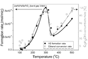
- the temperature dependence of ethanol reforming with this ferroelectric carrier catalyst is shown in the graph of FIG.
- the graph of FIG. 1 shows the amount of hydrogen gas generated when vaporized ethanol is brought into contact with the ferroelectric support catalyst, and the ethanol conversion rate by appropriately adjusting the temperature of the ferroelectric support catalyst. Shows the results.
- the catalytic ability of the ferroelectric-supported catalyst starts to increase around the Curie point (Tc), decreases at a high temperature sufficiently away from the Curie point (Tc), and further increases to a higher temperature. It becomes bigger again by becoming. That is, the catalytic activity is expressed in a low temperature range.
- the catalytic activity is exhibited in the temperature range of 250 to 300 ° C., and the catalytic activity is in the temperature range of 300 to 400 ° C. higher than the temperature range where the catalytic activity is exhibited.
- the catalytic activity is specifically expressed in a temperature range lower than 300 ° C.
- the ferroelectric that is the carrier of the ferroelectric carrier catalyst has a predetermined size below the Curie point (Tc) and disappears above the Curie point (Tc). have.
- This electric polarization represents the magnitude of the internal electric field generated by the electric dipoles aligned in the ferroelectric phase of the ferroelectric.
- the ferroelectric has temperature dependence of the dielectric constant, and the dielectric constant is remarkably increased in the vicinity of the Curie point (Tc). .
- the metal or metal oxide supported on the ferroelectric material which is a carrier in the ferroelectric carrier catalyst generally exhibits catalytic activity at a relatively high temperature.
- the polarization of the ferroelectric material disappears, and it is considered that a large polarization fluctuation is generated. It is considered that electrons in the metal oxide are greatly oscillated.
- the inventors of the present invention call the vibration caused by the polarization fluctuation of electrons in the metal or metal oxide supported on the ferroelectric substance as “charge fluctuation”.
- the charge fluctuation is large in the vicinity of the Curie point (Tc) and is higher than the Curie point (Tc). It gets smaller on the side.
- the Fermi level of the metal or metal oxide supported on the ferroelectric substance fluctuates, and an electron-hole pair is formed on the metal or metal oxide metal surface, This electron-hole pair is considered to be used for the catalytic reaction.
- Tc Curie point
- the ferroelectric carrying the metal or the metal oxide has a relatively low Curie point (Tc), so that the catalytic activity can be expressed at a low temperature. I think I can do it.
- the ferroelectric carrier catalyst of the present invention it is considered that the ferroelectric carrier catalyst is affected by the charge fluctuation, so that the ferroelectric band gap supporting the metal or the metal oxide is supported by the ferroelectric material. It can be seen that the work function of the metal or metal oxide is important. In the ferroelectric carrier catalyst of the present invention, it is considered that an electron-hole pair contributing to the catalytic reaction is formed by changing the Fermi level of the metal supported by the ferroelectric or the metal oxide. Because.
- the band gap of the ferroelectric is preferably in the range of 3.2 to 4.0 eV, more preferably 3.5 to 4.0 eV.
- the band gap of the ferroelectric is within this range, it means that the ferroelectric has no or little oxygen deficiency or impurities, and a highly active catalyst can be obtained at low temperature by polarization fluctuation.
- the band gap is calculated from the absorption edge of the reflection spectrum by measuring the reflection spectrum using a device incorporating an integrating sphere unit (ISN-470) into the Shimadzu spectrophotometer V-550. did.
- ISN-470 an integrating sphere unit
- the reflection spectrum is measured using the powder sample holder PSH-001. It was measured.
- ferroelectrics are spread evenly on a 25 mm aperture cell inside the holder with a thickness of about 1 to 2 mm, fixed by pressing with a quartz glass window, and light is incident from this quartz glass window and reflected by the ferroelectric.
- the spectrum obtained by the spectrophotometer has the reflectance (% R) on the vertical axis and the wavelength (nm) on the horizontal axis.
- the work function of the metal in the metal or metal oxide is preferably in the range of 4.5 to 6. OeV, more preferably 5.0 to 6.0 eV.
- the metal supported by the ferroelectric can be caused to fluctuate in the potential potential of the metal on the same time scale by being oscillated by the polarization fluctuation of the ferroelectric. .
- the fluctuation of the potential potential of the metal causes charge fluctuations in the metal or metal oxide supported on the ferroelectric, facilitating the exchange of electrons with reactants such as hydrocarbon gas diffused from the outside. It is considered that high activity is expressed even at a relatively low temperature.
- the metal supported on the ferroelectric Pd, Rh, Au, Ru, Ni, Pt, Cu, Fe, Ag, Co, In, Mg, Bi, Sn, Mn are preferable, and at least one of these, Alternatively, it may be a plurality of kinds of alloys, or one or more kinds of metal oxides. These metals or metal oxides have a metal work function in the above range, and the potential potential of the metal due to the polarization fluctuation of the ferroelectric is sufficiently oscillated, so that it is considered that high activity is exhibited at a low temperature.
- the metal supported by the ferroelectric or metal oxide metal is in ohmic contact with the ferroelectric near the conduction band of the ferroelectric, and therefore the ferroelectric
- the potential potential of the metal due to the fluctuation of the polarization is not sufficiently fluctuated, so that the activity of the catalyst tends to be insufficient.
- the work function is larger than 6.0 eV
- the metal supported on the ferroelectric or the metal of the metal oxide forms a Schottky junction in the vicinity of the electron band of the ferroelectric. The characteristic appears remarkably, and the activity tends to be insufficient due to the limited fluctuation of the potential potential of the metal.
- the ferroelectric carrier catalyst of the present invention uses a ferroelectric material in the form of fine particles and a metal or metal oxide in the form of fine particles.
- the fine particles of the ferroelectric material have an average particle diameter of 10 to 200 nm, Is preferably in the range of 10 to 100 nm.
- the average particle size of the ferroelectric When the average particle size of the ferroelectric is less than 10 nm, the polarization fluctuation generated in the ferroelectric becomes extremely small, so that there is a high possibility that sufficient activity cannot be obtained when the ferroelectric support catalyst is used. In addition, when the average particle size of the ferroelectric exceeds 200 nm, the average particle size of the supported metal or metal oxide is large, although it depends on the amount of the metal or metal oxide supported on the ferroelectric. Therefore, the activity may be insufficient when a ferroelectric support catalyst is used.
- the average particle diameter of the ferroelectric is measured using a scanning transmission electron microscope (STEM) (Hitachi: model S-5500) or a field emission electron microscope (field emission TEM) (JEOL: JEM-2100F). Then, a fine particle ferroelectric substance was photographed, and the particle diameters of 50 fine particles were measured to obtain an average value.
- STEM scanning transmission electron microscope
- field emission TEM field emission electron microscope
- Ferroelectric materials are usually prepared with a particle size larger than 10 to 200 nm, and the average particle size is adjusted and selected to 10 to 200 nm by pulverization using an appropriate pulverizer such as a bead mill. It is preferable.
- the ferroelectric is generally polycrystalline and has crystallites, but the crystallite diameter of the ferroelectric is preferably in the range of 5 to 100 nm, more preferably 7 to 50 nm.
- the crystallite diameter of the ferroelectric When the crystallite diameter of the ferroelectric is less than 5 nm, it means that the crystallinity of the ferroelectric is low. Therefore, the polarization fluctuation generated in the ferroelectric does not become sufficiently large, so that sufficient activity is achieved. May not be obtained. Further, when the crystallite diameter of the ferroelectric exceeds 100 nm, it is not only difficult to obtain, but there may be a demerit that the average particle diameter of the ferroelectric is increased.
- D K ⁇ / ⁇ cos ⁇
- D Crystallite diameter (angstrom)
- K Scherrer constant
- ⁇ X-ray wavelength (1.7889 Angstrom Cu lamp
- ⁇ Half width (rad)
- ⁇ reflection angle.
- the finely divided metal or metal oxide preferably has an average particle diameter of 1 to 20 nm, more preferably 2 to 15 nm.
- the average particle size of the metal or metal oxide is less than 1 nm, it is difficult to obtain.
- the average particle diameter of the metal or metal oxide exceeds 20 nm, sufficient activity is often not obtained regardless of the type of metal and the supported amount described later. This is thought to be because the electron-hole pairs generated by the polarization fluctuation of the ferroelectric material disappeared by recombination before reaching the surface of the metal or metal oxide, and did not contribute to the catalytic reaction. It is done.
- the measurement method of the average particle diameter of the finely divided metal or metal oxide can be calculated from the CO adsorption amount.
- the amount of CO adsorption was measured using a catalyst analyzer (BEL-CAT, manufactured by Nippon Bell Co., Ltd.).
- the pretreatment for the measurement was based on “Standardization of Measurement Method Using Reference Catalyst” of the Reference Catalyst Committee of the Catalysis Society of Japan.
- the average atomic weight and average atomic radius of the supported metal are calculated from the ratio of the supported metal, and the calculation formula described in the instruction manual of the catalyst analyzer (BEL-CAT) Can be used to calculate.
- the amount of finely divided metal or metal oxide supported by finely divided ferroelectric is 1 to 30 parts by mass in terms of metal or metal oxide in terms of metal with respect to 100 parts by mass of ferroelectric, Is preferably in the range of 1.5 to 20 parts by mass.
- metal or metal oxide is converted to metal and is less than 1 part by mass with respect to 100 parts by mass of the ferroelectric, sufficient activity may not be obtained.
- metal or metal oxide exceeds 30 parts by mass in terms of metal with respect to 100 parts by mass of the ferroelectric, the particle size of the metal or metal oxide supported on the ferroelectric increases. In some cases, sufficient activity may not be obtained.
- the fine particles of the metal or metal oxide supported on the fine particles of the ferroelectric material are prepared by mixing a predetermined amount of the fine particle ferroelectric material and a predetermined amount of the fine particle metal or metal oxide. By putting the container in a predetermined container and heating the container while rotating, the ferroelectric substance and the metal or metal oxide are heated while stirring to support the metal or metal oxide on the surface of the ferroelectric substance. be able to.
- a homogeneous ferroelectric carrier catalyst can be produced by supporting a metal or metal oxide on a ferroelectric material by an impregnation / adsorption process, a drying process, and a heating process as described below.
- ⁇ Impregnation / adsorption process First, water is dropped onto a predetermined amount of fine-particle ferroelectric material to form a paste, and the amount of dropped water, that is, the amount of water absorption is obtained. Next, a metal salt aqueous solution having the same amount as the amount of dropped water is prepared using a metal salt supported on the ferroelectric substance. Here, the amount of the metal contained in the aqueous metal salt solution is 1-30 in terms of metal with respect to 100 parts by mass of the ferroelectric material based on the mass of the paste-like ferroelectric material before dripping water. Mass parts. Next, a paste-form ferroelectric substance is mixed with the metal salt aqueous solution to prepare a raw material liquid.
- ⁇ Drying process> By drying the raw material liquid, water is generally removed from the raw material liquid to obtain a raw material powder. Any drying method may be used as long as moisture can be substantially removed from the raw material liquid.
- the drying temperature is generally 80 to 200 ° C., preferably 100 to 180 ° C.
- the drying time varies depending on the drying temperature, but is generally 1 to 48 hours.
- Heating atmosphere may be an oxidizing atmosphere of air, oxygen and the like, may be an inert gas atmosphere such as N 2, He or Ar, even under a reducing gas atmosphere such as H 2 Also good.
- the metal supported on the ferroelectric by heating in an oxidizing atmosphere may be used as a metal oxide.
- the heating temperature can be appropriately determined according to the metal to be bonded to the ferroelectric, and is generally preferably in the range of 200 to 600 ° C., more preferably 250 to 550 ° C.
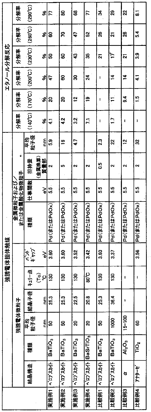
- Ethanol decomposition reaction of the ferroelectric support catalyst (1) The powdered ferroelectric support catalyst (1) is pressed and crushed, and then sized to prepare a granular sample with a particle size of 335 to 710 ⁇ m.
- the reactor was charged with O.05 g and subjected to the reaction.
- the reaction was carried out by introducing ethanol with a pulse size of 1 ⁇ L by the pulse method and changing the reaction temperature to 140, 170, 200, 230, 260 and 290 ° C.
- the product gas was quantified using a gas chromatograph (manufactured by Shimadzu Corporation: GC-8A).
- a thermal conductivity detection (Thermal Conductivity Detector, TCD) was used as a detector, and PEG6000 Shimarite 10% TPA 60-80 mesh was used as a capillary column. Helium was used as the carrier gas and the flow rate was 50 mL / min.
- Example 2 Preparation of ferroelectric support catalyst (2)
- the amount of metal supported and the average particle size were measured. The results are shown in Table 1.
- ethanol decomposition activity was evaluated and the results are shown in Table 1.
- Example 3 Preparation of ferroelectric support catalyst (3)
- a ferroelectric carrier catalyst (3) was prepared in the same manner except that it was used.
- the amount of metal carried and the average particle size were measured. The results are shown in Table 1.
- ethanol decomposition activity was evaluated and the results are shown in Table 1.
- Example 4 Preparation of ferroelectric-supported catalyst (4)
- BaSrTiO 3 was prepared as a ferroelectric by the method described in Patent Documents 1 to 3. The average particle size and particle size of the obtained BaSrTiO 3 were measured, and the results are shown in Table 1.
- a ferroelectric carrier catalyst (4) was prepared in the same manner as in Example 1 except that 100 g of BaSrTiO 3 particles were used as the ferroelectric.
- the amount of metal carried and the average particle diameter were measured. The results are shown in Table 1.
- ethanol decomposition activity was evaluated and the results are shown in Table 1.
- Example 2 Preparation of Ferroelectric Support Catalyst (R2)
- a ferroelectric carrier catalyst (R2) was prepared in the same manner except that 100 g was used. With respect to the obtained ferroelectric carrier catalyst (R2), the amount of metal supported and the average particle diameter were measured, and the results are shown in Table 1. Moreover, ethanol decomposition activity was evaluated and the results are shown in Table 1.
- Example 3 Preparation of non-ferroelectric (paraelectric) supported catalyst (R3)
- fine ⁇ -Al 2 0 3 Nippon Light Metal (Nippon Light Metal)
- a non-ferroelectric (paraelectric) catalyst (R3) was prepared in the same manner except that 100 g of a particle size distribution of 15 to 100 nm was used.
- the amount of metal supported and the average particle diameter were measured, and the results are shown in Table 1.
- ethanol decomposition activity was evaluated and the results are shown in Table 1.
- Example 4 Preparation of non-ferroelectric (paraelectric) support catalyst (R4)
- fine TiO 2 manufactured by JGC Catalysts & Chemicals Co., Ltd.
- the amount of metal supported and the average particle diameter were measured, and the results are shown in Table 1.
- ethanol decomposition activity was evaluated and the results are shown in Table 1.
- the ferroelectric carrier catalyst and the method for producing the same according to the present invention it is possible to provide a novel ferroelectric carrier catalyst excellent in low-temperature activity, so that the choice of catalyst can be increased.
- the target catalyst can be easily obtained by adjusting the Curie point (Tc) of the ferroelectric as required.
Landscapes
- Chemical & Material Sciences (AREA)
- Engineering & Computer Science (AREA)
- Materials Engineering (AREA)
- Organic Chemistry (AREA)
- Chemical Kinetics & Catalysis (AREA)
- Catalysts (AREA)
Abstract
低温活性に優れた新規な強誘電体担体触媒及びその製造方法を提供する。 微粒子状とした強誘電体の表面に金属または金属酸化物を担持させて成る強誘電体担体触媒において、強誘電体のキュリー点(Tc)が0~200℃であって、300℃以下で触媒活性を発現するとともに、触媒活性が発現した温度域よりも高温側で触媒活性が低下することで、300℃よりも低温の温度域で特異的に触媒活性が発現する強誘電体担体触媒とする。この強誘電体担体触媒を、ペースト状とした強誘電体から成る原料液を作成する工程と、この原料液を乾燥させて原料粉末を作成する工程と、この原料粉末を加熱する工程とで製造する。
Description
本発明は、低温活性に優れた強誘電体担体触媒及びその製造方法に関する。
従来、適当な担体に金属を担持させた触媒が酸化還元触媒として用いられている。しかしながら、既存の酸化還元触媒において、強誘電体を担体として用いることは必ずしも広く知られていない。
本発明者の一人は、強誘電体であるチタン酸鉛(PbxSr1-xTi03)の表面に析出した鉛が酸化せず、金属の状態となっていることを発見し、このチタン酸鉛(PbxSr1-xTi03)が新規な触媒として利用できることを提案した。なお、チタン酸鉛(PbxSr1-xTi03)は、共沈法で作成している(特許文献1:特開2009-207977号公報、特許文献2:特開2009-207978号公報、特許文献3:2009-207979号公報)。
しかしながら、共沈法で強誘電体を作製する場合には、共沈法が利用できる金属の組み合わせでしか強誘電体を作製できず、加えて強誘電体の収量がわずかであるために製造効率が低く、経済性の点で問題があった。
そこで、さらに検討した結果、粉末状とした強誘電体と粉末状とした金属との混合物を撹拌しながら焼成することによって、金属の一部を強誘電体の表面に担持させた強誘電体担体触媒を発明した。特に、この強誘電体担体触媒では、強誘電体に担持される金属を、強誘電体の表面から担持された金属表面までの距離を10nm以下とすることが望ましい。すなわち、強誘電体に担持される金属は、粒子径が10nm以下であることが望ましいことを発見した(特許文献4:特開2012-161751号公報)。
本発明者らは、強誘電体担体触媒に関する研究を行う中で、様々な種類の強誘電体を担体として強誘電体担体触媒の作製を行っていたところ、キュリー点(Tc)の低い強誘電体を担体とした場合に、通常の触媒活性が発現する温度よりも低い温度において触媒活性が発現する現象を見出した。
本発明者らは、この現象の理由をより詳細に研究していくことで、本発明を完成するに到った。本発明は、担体である強誘電体に金属または金属酸化物を担持させた触媒であって、低温活性に優れた触媒を提供することを目的としている。
本発明の強誘電体担体触媒は、微粒子状とした強誘電体の表面に金属または金属酸化物を担持させて成る強誘電体担体触媒において、強誘電体のキュリー点(Tc)が0~200℃であって、300℃以下で触媒活性を発現するとともに、触媒活性が発現した温度域よりも高温側で触媒活性が低下することで、300℃よりも低温の温度域で特異的に触媒活性が発現する強誘電体担体触媒である。
さらに、本発明の強誘電体担体触媒は、誘電体のバンドギャップが3.2~4.0eVであって、強誘電体の平均粒子径が10~200nmであるとともに、金属または金属酸化物に含まれる金属の仕事関数が4.5~6eVであって、強誘電体に担持された金属または金属酸化物の平均粒子径が1~20nmであり、強誘電体100質量部に対して、金属または金属酸化物を金属に換算して1~30質量部含有していることにも特徴を有する。
さらには、本発明の強誘電体担体触媒は、強誘電体がABO3で表されるペロブスカイト型結晶構造を有する結晶であって、元素AがBaまたは、Ca、Sr、Li、K、Na、Ag、La、およびTmから選ばれる少なくとも1種の元素とBaであり、元素BがTiまたは、Nb、Fe、Mn、Ta、ZrおよびLaから選ばれる少なくとも1種の元素とTiであり、金属または金属酸化物に含まれる金属がPd、Rh、Au、Ru、Ni、Pt、Cu、Fe、Ag、Co、In、Mg、Bi、Sn、Mnから選ばれる少なくとも1種であることにも特徴を有するものである。
また、本発明の強誘電体担体触媒の製造方法では、キュリー点(Tc)が0~200℃である微粒子状とした強誘電体の表面に、金属または金属酸化物を担持させることで、300℃以下で触媒活性を発現すとともに、触媒活性が発現した温度域よりも高温側で触媒活性が低下することで、300℃よりも低温の温度域で特異的に触媒活性が発現する強誘電体担体触媒の製造方法において、強誘電体に水を加えてペースト状とし、このペースト状の強誘電体に、金属の塩を溶解させて前記の水と等量とした金属塩水溶液を混合して原料液を作成する工程と、この原料液を乾燥させて原料粉末を作成する工程と、この原料粉末を加熱する工程とを有するものである。
本発明では、低温活性に優れており、各種の触媒反応に用いることができる強誘電体担体触媒を提供できる。
以下、本発明に係る強誘電体担体触媒及びその製造方法について説明する。
本発明に係る強誘電体担体触媒は、微粒子状とした強誘電体を担体として、この担体の表面に金属または金属酸化物を担持させているものである。
本発明に係る強誘電体担体触媒は、微粒子状とした強誘電体を担体として、この担体の表面に金属または金属酸化物を担持させているものである。
強誘電体とは、一般的に外部からの電場が印加されていない状態でも、電気双極子が整列し、自発的に電気分極を形成した状態を有する物質である。
電気双極子とは、強誘電体等の誘電体の物体内に存在している電荷分布の不均一によって生じているミクロサイズの電気的な状態である。すなわち、電気双極子は、相対的に電子が多いことで電気的に負に帯電していると見なせる微小領域と、相対的に電子が少ないことで電気的に正に帯電していると見なせる微小領域とで1つの対を形成した状態であって、微小な電場を形成していることとなっている。
特に、強誘電体では、その結晶構造に起因して電荷分布の不均一が生じることで電気双極子が生じるとともに、各電気双極子の向きが揃っている、すなわち整列し分極した状態となっている。この状態を強誘電体における強誘電相と呼んでいる。
しかし、キュリー点(Tc)を超える温度となると、強誘電体では、電子の運動エネルギーが大きくなることにより電荷分布の変動が大きくなって、電気双極子の向きが揃わない状態が生じることとなる。この電気双極子の向きが揃っていないランダムな状態を常誘電相と呼んでいる。すなわち、キュリー点(Tc)とは、強誘電相と常誘電相との相転移温度となっている。
本発明者の一人は、特許文献4:特開2012-161751号公報において、粉末状とした強誘電体の表面に金属を担持させることで触媒となることを報告している。特に、同文献において、強誘電体で生じた分極揺らぎによって強誘電体と界面接触した金属の電位ポテンシャルが揺動されることで電子-正孔対が生成され、この生成された電子-正孔対が強誘電体に担持された金属の表面に移動して、触媒としての反応を生じさせていると考えていた。
この「分極揺らぎ」とは、上述した電気双極子の向きの時空間的な揺らぎである。特に、強誘電体においては、強誘電相では分極揺らぎはほとんど存在し得ないが、常誘電相となることで生じる。
なお、常誘電相での分極揺らぎに起因して触媒活性が発現するのであれば、状態的には同じである常誘電体を担体として金属等を担持させても同様の触媒機能を発現すると考えられる。しかし、常誘電体を担体として用いた場合では、本発明の強誘電体担体触媒で顕著な低温での触媒活性が発現しない。
このことから、本発明の強誘電体担体触媒では、担体としての強誘電体がキュリー点(Tc)より低い温度において強誘電相となっている際の秩序状態が、キュリー点(Tc)より高い温度で融けた状態となって生じた分極揺らぎが低温での触媒活性の発現に寄与していると考えられる。したがって、強誘電体担体触媒を構成するための担体は、キュリー点(Tc)を有する強誘電体である必要がある。
キュリー点(Tc)を有する強誘電体としては、ABO3で表されるペロブスカイト型結晶構造、いわゆる酸素八面体構造を有する結晶であるものが好ましい。
ここで、元素Aは、Baまたは、Ca、Sr、Li、K、Na、Ag、La、およびTmから選ばれる少なくとも1種の元素とBaであり、元素Bは、Tiまたは、Nb、Fe、Mn、Ta、ZrおよびLaから選ばれる少なくとも1種の元素とTiであることが望ましい。これらの元素を配合したペロブスカイト型結晶構造とすることで、結晶性に優れた強誘電体とすることができ、キュリー点(Tc)が低く、低温活性に優れた強誘電体担体触媒を得ることができる。
特に、前記Bが、Tiまたは、Nb、Fe、Mn、Ta、ZrおよびLaから選ばれる少なくとも1種の元素とTiである場合には、Tiの元素の割合が50%以上であることが好ましい。これらの元素からなるペロブスカイト型結晶構造の強誘電体とすることで、キュリー点(Tc)が低く、低温活性に優れた強誘電体担体触媒を得ることができる。
強誘電体のキュリー点(Tc)は、0~200℃、さらには20~180℃の範囲にあることが好ましい。
なお、キュリー点(Tc)が0℃未満となる強誘電体は、その強誘電体を得ること自体が困難である。
一方、キュリー点(Tc)が200℃を超える強誘電体は、200℃を超える温度領域で分極揺らぎが生じることとなるものの、分極揺らぎによる触媒活性の向上効果が期待できる温度領域では、強誘電体に担持させた金属または金属酸化物自体が有している触媒活性も発現するために、どちらの触媒活性の効果が主として効いているかを判別が極めて困難である。また、その場合には、触媒活性が低温の温度領域で発現しているとは言いにくい。
これらのことから、強誘電体のキュリー点(Tc)は、0~200℃、さらには20~180℃の範囲にあることが好ましい。
より具体的な例を示して、本発明の強誘電体担体触媒における低温での触媒活性の発現について説明する。
ここで示す強誘電体担体触媒は、強誘電体としてチタン酸バリウム(BaTiO3)を用い、後述する方法でパラジウム(Pd)をチタン酸バリウム(BaTiO3)に担持させているものである。また、チタン酸バリウム(BaTiO3)は、固相反応法でバルク作成したものをビーズミルで平均粒子径50nm程度に粉砕したものであり、パラジウム(Pd)は1~2nm程度の粒子径としてチタン酸バリウム(BaTiO3)に高分散させて担持させている。チタン酸バリウム(BaTiO3)のキュリー点(Tc)は約130℃である。
この強誘電体担体触媒によるエタノール改質の温度依存性を図1のグラフに示す。すなわち、図1のグラフは、気化させたエタノールを強誘電体担体触媒に接触させた際の水素ガスの発生量、及びエタノールの変換率を、強誘電体担体触媒の温度を適宜調整して計測した結果を示している。
図1のグラフから明らかなように、強誘電体担体触媒の触媒能は、キュリー点(Tc)を超えたあたりから大きくなり始め、キュリー点(Tc)から充分離れた高温で低下し、さらに高温となることで再度大きくなっている。すなわち、触媒活性が低温の温度領域で発現している。
すなわち、本実施例の強誘電体担体触媒では、250~300℃の温度域で触媒活性を発現すとともに、触媒活性が発現した温度域よりも高温側の300~400℃の温度域で触媒活性が低下することで、300℃よりも低温の温度域で特異的に触媒活性が発現している。
このような結果が得られることについて考察した結果、本発明者らは、以下のようなメカニズムが存在していると考えている。
まず、図2(a)に示すように、強誘電体担体触媒の担体である強誘電体は、キュリー点(Tc)未満では所定の大きさで、キュリー点(Tc)以上では消失する電気分極を有している。この電気分極とは、強誘電体の強誘電相で揃っている電気双極子によって生成される内部電場の大きさを表している。
また、強誘電体では、図2(b)に示すように、誘電率の温度依存性があることが知られており、キュリー点(Tc)近傍で誘電率が著しく増大することとなっている。
一方、強誘電体担体触媒において担体である強誘電体に担持される金属または金属酸化物は、図2(c)に示すように、一般的に比較的高温の状態において触媒活性を示すことが知られている。
この金属または金属酸化物が強誘電体に担持されて強誘電体担体触媒となることで、キュリー点(Tc)近傍で増大した誘電率にアシストされて、図2(d)に示すように通常よりも低温側においても触媒活性が一旦向上し、N字型の特性曲線を描くものと考えられる。
ここで、誘電率にアシストされると説明したが、図2(d)に基づく説明としての表現であり、正確には、以下のメカニズムが存在しているものと考えられる。
すなわち、キュリー点(Tc)を超えた温度域では、強誘電体の分極は消失し、大きな分極揺らぎが発生していると考えられ、この分極揺らぎによって、強誘電体に担持された金属中または金属酸化物中の電子は大きく振動されているものと考えられる。
本発明者らは、この強誘電体に担持された金属中または金属酸化物中の電子の分極揺らぎに起因した振動を「電荷ゆらぎ」と呼んでいる。
特に、図2(b)に示すように、キュリー点(Tc)の近傍では誘電率が大きくなっているため、電荷ゆらぎはキュリー点(Tc)の近傍で大きく、キュリー点(Tc)よりも高温側では小さくなる。
この電荷揺らぎによる電荷分布変動によって、強誘電体に担持された金属または金属酸化物の金属のフェルミ準位が変動し、金属または金属酸化物の金属の表面に電子-正孔対が形成され、この電子-正孔対が触媒反応に利用されていると考えられる。一方、キュリー点(Tc)よりも高温側では、電荷揺らぎが小さくなることで十分な電子-正孔対が形成されなくなり、触媒活性が低下するものと考えられる。
このように、本発明の強誘電体担体触媒では、金属または金属酸化物を担持する強誘電体が比較的低温のキュリー点(Tc)を有することで、低温での触媒活性を発現させることができると考えている。
さらには、本発明の強誘電体担体触媒では、電荷揺らぎの影響を受けていると考えられることから、金属または金属酸化物を担持する強誘電体のバンドギャップ、及び強誘電体に担持される金属または金属酸化物の仕事関数が重要であることがわかる。本発明の強誘電体担体触媒では、強誘電体に担持された金属または金属酸化物の金属のフェルミ準位が変動することで触媒反応に寄与する電子-正孔対が形成されると考えられるからである。
この点について検討した結果、強誘電体のバンドギャップは3.2~4.0eV、さらには3.5~4.0eVの範囲にあることが好ましい。強誘電体のバンドギャップはこの範囲である場合には、強誘電体に酸素欠損あるいは不純物が無いか少ないことを意昧しており、分極揺らぎにより低温で活性の高い触媒を得ることができる。
なお、本発明では、バンドギャップは、島津製分光光度計V-550に積分球ユニット(ISN-470)を組み込んだ装置を用いて反射スペクトルを測定することにより、その反射スペクトルの吸収端から算出した。本来ならば、透過スペクトルを測定するのが望ましいが、用いた強誘電体は微粒子粉末体のため検出光を透過させることができないため、粉末試料用ホルダーPSH-001を利用して、反射スペクトルを測定した。特に、強誘電体は、ホルダー内部の25mm口径のセルに厚さ1~2mm程度として均等に敷き詰め、石英ガラス窓で押さえつけて固定し、この石英ガラス窓から光を入射させて強誘電体で反射させ、反射光のスペクトルから反射率を求める形式を採用した。分光光度計により得られるスペクトルは縦軸が反射率(%R)、横軸が波長(nm)となる。高エネルギー側(低波長側)に現れる吸収端、すなわち反射率が0に漸近する波長領域を確認し、1240÷吸収端波長=バンドギャップ(eV)とした。
また、金属または金属酸化物中の金属の仕事関数は、4.5~6.OeV、さらには5.0~6.0eVの範囲が好ましい。
仕事関数が4.5~6.0eVの金属を強誘電体に担持させた場合には、強誘電体とショットキー接合し、生成させたいガスの酸化還元準位と強誘電体の伝導帯もしくは価電子帯の裾を階段状に架橋することできる。
したがって、キュリー点(Tc)近傍において、強誘電体に担持させた金属には、強誘電体の分極揺らぎに揺動されることで同じ時間スケールで金属の電位ポテンシャルの変動を生じさせることができる。
そして、金属の電位ポテンシャルが変動することで、強誘電体に担持された金属または金属酸化物に電荷揺らぎが生じて、外部から拡散してきた炭化水素ガス等の反応物との電子の授受が促進され、比較的低温でも高い活性を発現すると考えられる。
強誘電体に担持される金属としては、Pd、Rh、Au、Ru、Ni、Pt、Cu、Fe、Ag、Co、In、Mg、Bi、Sn、Mnが好適であり、これらの少なくとも一種、または複数種の合金、あるいは一種または複数種からなる金属酸化物であってもよい。これらの金属または金属酸化物は、金属の仕事関数が前記の範囲にあり、強誘電体の分極揺らぎによる金属の電位ポテンシャルが十分に揺動され、低温で高い活性を発現すると考えられる。
なお、仕事関数が4.5eVよりも小さい場合には、強誘電体に担持させた金属または金属酸化物の金属が、強誘電体の伝導帯付近で強誘電体とオーミック接合するため、強誘電体の分極揺らぎによる金属の電位ポテンシャルが十分には揺動されず、そのため触媒の活性が不充分となる傾向にある。また、仕事関数が6.0eVよりも大きい場合には、強誘電体に担持させた金属または金属酸化物の金属が、強誘電体の電子帯付近でショットキー接合するため、強誘電体のp型特性が顕著に現れることとなり、金属の電位ポテンシャルの揺動が限定されることで活性が不充分となる傾向にある。
以下において、本発明の強誘電体担体触媒の製造方法を説明する。
本発明の強誘電体担体触媒は、微粒子状とした強誘電体と、微粒子状とした金属または金属酸化物を用いるが、微粒子状とした強誘電体は、平均粒子径を10~200nm、さらには10~100nmの範囲とすることが好ましい。
強誘電体の平均粒子径が10nm未満の場合は、強誘電体に生じる分極揺らぎが極端に小さくなるために、強誘電体担体触媒とした際に充分な活性が得られない可能性が高い。また、強誘電体の平均粒子径が200nmを超える場合は、強誘電体に担持させた金属または金属酸化物の担持量によっても異なるが、担持させた金属または金属酸化物の平均粒子径が大きくなる傾向にあるために、強誘電体担体触媒とした際に活性が不充分となる可能性がある。
強誘電体の平均粒子径の測定方法は、走査透過型電子顕微鏡(STEM)(日立製作所:機種S-5500)もしくは電解放出形電子顕微鏡(フィールドエミッションTEM)(日本電子:JEM-2100F)を用いて微粒子状の強誘電体を撮影し、50個の微粒子について粒子径を測定し、その平均値とした。
強誘電体は、通常、粒子径が10~200nmよりも大きい状態で作成されており、ビーズミル等の適宜の粉砕機を用いて粉砕することで、平均粒子径を10~200nmに調整・選別することが好ましい。
また、強誘電体は一般的に多結晶体であって、結晶子を有しているが、強誘電体の結晶子径は5~100nm、さらには7~50nmの範囲にあることが好ましい。
強誘電体の結晶子径が5nm未満の場合は、強誘電体の結晶性が低いことを意味しており、このため、強誘電体に生じる分極揺らぎが十分に大きくならないことにより、充分な活性が得られない可能性がある。また、強誘電体の結晶子径が100nmを超える場合は、得ることが困難であるだけでなく、強誘電体の平均粒子径が大きくなることのデメリットが生じる可能性がある。
なお、結晶子径の計測は、X線回折測定装置で、2θ=31.5度付近の(110)面のピークの半価幅を測定し、下記Scherrerの式により計算して求めた。
D=Kλ/βcosθ
D:結晶子径(オングストローム)、
K: Scherrer定数、
λ:X線波長(1.7889オングストロームCuランプ)、
β:半価幅(rad)、
θ:反射角。
D=Kλ/βcosθ
D:結晶子径(オングストローム)、
K: Scherrer定数、
λ:X線波長(1.7889オングストロームCuランプ)、
β:半価幅(rad)、
θ:反射角。
微粒子状とした金属または金属酸化物は、平均粒子径を1~20nm、さらには2~15nmの範囲とすることが好ましい。
金属または金属酸化物の平均粒子径が1nm未満の場合は、得ることが困難である。また、金属または金属酸化物の平均粒子径が20nmを超える場合は、金属の種類によらず、また、後述する担持量によらず、充分な活性が得られないことが多い。これは、強誘電体の分極揺らぎによって生成された電子-正孔対が、金属または金属酸化物の表面に達する前に再結合等により消失して、触媒反応に寄与できていないためだと考えられる。
微粒子状とした金属または金属酸化物の平均粒子径の測定方法は、CO吸着量から算出することができる。CO吸着量は、触媒分析装置(日本ベル株式会社製:BEL-CAT)を用いて測定した。測定のための前処理は、触媒学会参照触媒委員会の「参照触媒を用いた測定法の標準化」を参考にした。なお、CO吸着からの金属の平均粒子は、担持した金属の割合より担持金属の平均原子量および平均原子半径を算出し、触媒分析装置(BEL-CAT)の取扱説明書に記載されている計算式を用いて算出することができる。
微粒子状とした強誘電体による微粒子状とした金属または金属酸化物の担持量は、強誘電体100質量部に対して、金属または金属酸化物は金属に換算して1~30質量部、さらには1.5~20質量部の範囲にあることが好ましい。
強誘電体100質量部に対して、金属または金属酸化物が金属に換算して1質量部満とした場合には、充分な活性が得られない可能性がある。また、強誘電体100質量部に対して、金属または金属酸化物が金属に換算して30質量部を超える場合には、強誘電体に担持された金属または金属酸化物の粒子径が大きくなり過ぎることがあり、充分な活性が得られない可能性がある。
微粒子状とした強誘電体への微粒子状とした金属または金属酸化物の担持は、所定量とした微粒子状の強誘電体と、所定量とした微粒子状の金属または金属酸化物とを混合し、所定の容器に入れて、その容器を回転させながら加熱することで、強誘電体と金属または金属酸化物を撹拌しながら加熱して、強誘電体の表面に金属または金属酸化物を担持させることができる。
なお、このように回転撹拌させながら強誘電体の表面に金属または金属酸化物を担持させた場合では、強誘電体に担持されない金属または金属酸化物が生じることがあり、製造ロットごとのバラツキがおおきくなる傾向がある。
そこで、以下のように含浸・吸着工程、乾燥工程および加熱工程によって金属または金属酸化物を強誘電体に担持させることで、均質な強誘電体担体触媒を製造することができる。
<含浸・吸着工程>
まず、所定量の微粒子状の強誘電体に水を滴下してペースト状とするとともに、滴下した水の量、すなわち吸水量を求める。
ついで、強誘電体に担持させる金属の塩を用いて、滴下した水の量と同量の金属塩水溶液を調製する。ここで、金属塩水溶液に含まれる金属の量は、ペースト状とした強誘電体の水の滴下前の質量を基準として、強誘電体100質量部に対して、金属に換算して1~30質量部としている。
次いで、金属塩水溶液にペースト状とした強誘電体を混合して、原料液を作成する。
まず、所定量の微粒子状の強誘電体に水を滴下してペースト状とするとともに、滴下した水の量、すなわち吸水量を求める。
ついで、強誘電体に担持させる金属の塩を用いて、滴下した水の量と同量の金属塩水溶液を調製する。ここで、金属塩水溶液に含まれる金属の量は、ペースト状とした強誘電体の水の滴下前の質量を基準として、強誘電体100質量部に対して、金属に換算して1~30質量部としている。
次いで、金属塩水溶液にペースト状とした強誘電体を混合して、原料液を作成する。
<乾燥工程>
原料液を乾燥させることで、原料液から水分を概ね除去して原料粉末とする。
原料液から水分を概ね除去することができれば、乾燥方法はどのような方法であってもよい。ちなみに、乾燥温度は、概ね80~200℃、好ましくは100~180℃であり、乾燥時聞は乾燥温度によっても異なるが、概ね1~48時間である。
原料液を乾燥させることで、原料液から水分を概ね除去して原料粉末とする。
原料液から水分を概ね除去することができれば、乾燥方法はどのような方法であってもよい。ちなみに、乾燥温度は、概ね80~200℃、好ましくは100~180℃であり、乾燥時聞は乾燥温度によっても異なるが、概ね1~48時間である。
<加熱工程>
原料粉末を、適宜の雰囲気下で加熱することで、強誘電体に金属を接合させる。加熱雰囲気は、空気や酸素等の酸化雰囲気下であってもよいし、N2やHeあるいはAr等の不活性ガス雰囲気下であってもよいし、H2等の還元ガス雰囲気下であってもよい。特に、酸化雰囲気下で加熱することで、強誘電体に担持させた金属を金属酸化物としてもよい。
加熱温度は、強誘電体に接合させる金属に応じて適宜とすることができ、一般的には、200~600℃、さらには250~550℃の範囲にあることが好ましい。
原料粉末を、適宜の雰囲気下で加熱することで、強誘電体に金属を接合させる。加熱雰囲気は、空気や酸素等の酸化雰囲気下であってもよいし、N2やHeあるいはAr等の不活性ガス雰囲気下であってもよいし、H2等の還元ガス雰囲気下であってもよい。特に、酸化雰囲気下で加熱することで、強誘電体に担持させた金属を金属酸化物としてもよい。
加熱温度は、強誘電体に接合させる金属に応じて適宜とすることができ、一般的には、200~600℃、さらには250~550℃の範囲にあることが好ましい。
以下において、実施例により説明するが、本発明はこれらの実施例により限定されるものではない。
[実施例1]:強誘電体担体触媒(1)の調製
硝酸パラジウム水溶液(硝酸パラジウム濃度=4.347質量%)46gに、微粒子状の強誘電体としてBaTi03(関東電化工業(株)製:平均粒子径=50nm、結晶子径=25.3nm)100gを撹拌しながら添加した後、室温で3時間静置した。
ついで、150℃で24時間乾燥した後、空気雰囲気下で、400℃で3時間加熱処理することで強誘電体担体触媒(1)を調製した。
得られた強誘電体担体触媒(1)について、金属の担持量を原料の使用量からの計算値で示し、また平均粒子径を測定し、結果を表1に示す。
硝酸パラジウム水溶液(硝酸パラジウム濃度=4.347質量%)46gに、微粒子状の強誘電体としてBaTi03(関東電化工業(株)製:平均粒子径=50nm、結晶子径=25.3nm)100gを撹拌しながら添加した後、室温で3時間静置した。
ついで、150℃で24時間乾燥した後、空気雰囲気下で、400℃で3時間加熱処理することで強誘電体担体触媒(1)を調製した。
得られた強誘電体担体触媒(1)について、金属の担持量を原料の使用量からの計算値で示し、また平均粒子径を測定し、結果を表1に示す。
強誘電体担体触媒(1)のエタノール分解反応
粉末状の強誘電体担体触媒(1)をプレスして解砕し、ついで、整粒して粒子径が335~710μmの顆粒状サンプルを調製し、これを反応器にO.05g充填して反応に供した。
反応は、パルス法にてエタノールをパルスサイズ1μL導入し、反応温度を140,170,200,230,260及び290℃と変更して実施した。
生成ガスはガスクロマトグラフ(島津製作所製:GC-8A)を用いて定量した。このとき、検出器は熱伝導検出(Thermal Conductivity Detector,TCD)、キャピラリーカラムにはPEG6000 Shimarite 10% TPA 60~80meshを使用した。キャリアガスにはヘリウムを用い、流量は50mL/minとした。
分解率は、以下の式によって求め、各温度での分解率を表1に示す。
分解率(%)=(導入エタノール量/未反応エタノール量)/導入エタノール量×100
粉末状の強誘電体担体触媒(1)をプレスして解砕し、ついで、整粒して粒子径が335~710μmの顆粒状サンプルを調製し、これを反応器にO.05g充填して反応に供した。
反応は、パルス法にてエタノールをパルスサイズ1μL導入し、反応温度を140,170,200,230,260及び290℃と変更して実施した。
生成ガスはガスクロマトグラフ(島津製作所製:GC-8A)を用いて定量した。このとき、検出器は熱伝導検出(Thermal Conductivity Detector,TCD)、キャピラリーカラムにはPEG6000 Shimarite 10% TPA 60~80meshを使用した。キャリアガスにはヘリウムを用い、流量は50mL/minとした。
分解率は、以下の式によって求め、各温度での分解率を表1に示す。
分解率(%)=(導入エタノール量/未反応エタノール量)/導入エタノール量×100
[実施例2]:強誘電体担体触媒(2)の調製
実施例1において、硝酸パラジウム水溶液(硝酸パラジウム濃度=10.868質量%)46gを用いた以外は同様にして強誘電体担体触媒(2)を調製した。
得られた強誘電体担体触媒(2)について、金属の担持量と、平均粒子径を測定し、結果を表1に示す。また、エタノール分解活性を評価し、結果を表1に示す。
実施例1において、硝酸パラジウム水溶液(硝酸パラジウム濃度=10.868質量%)46gを用いた以外は同様にして強誘電体担体触媒(2)を調製した。
得られた強誘電体担体触媒(2)について、金属の担持量と、平均粒子径を測定し、結果を表1に示す。また、エタノール分解活性を評価し、結果を表1に示す。
[実施例3]:強誘電体担体触媒(3)の調製
実施例1において、強誘電体としてBaTi03(戸田工業(株)製:平均粒子径=20nm、結晶子径=22.5nm)100gを用いた以外は同様にして強誘電体担体触媒(3)を調製した。
得られた強誘電体担体触媒(3)について、金属の担持量と、平均粒子径を測定し、結果を表1に示す。また、エタノール分解活性を評価し、結果を表1に示す。
実施例1において、強誘電体としてBaTi03(戸田工業(株)製:平均粒子径=20nm、結晶子径=22.5nm)100gを用いた以外は同様にして強誘電体担体触媒(3)を調製した。
得られた強誘電体担体触媒(3)について、金属の担持量と、平均粒子径を測定し、結果を表1に示す。また、エタノール分解活性を評価し、結果を表1に示す。
[実施例4]:強誘電体担体触媒(4)の調製
特許文献1~3における手法により、強誘電体としてBaSrTi03を調整した。得られたBaSrTi03の平均粒子径および結品子径を測定し、結果を表1に示す。
ついで、実施例1において、強誘電体としてBaSrTi03粒子100gを用いた以外は同様にして強誘電体担体触媒(4)を調製した。
得られた強誘電体担体触媒(4)について、金属の担持量と、平均粒子径を測定し、結果を表1に示す。また、エタノール分解活性を評価し、結果を表1に示す。
特許文献1~3における手法により、強誘電体としてBaSrTi03を調整した。得られたBaSrTi03の平均粒子径および結品子径を測定し、結果を表1に示す。
ついで、実施例1において、強誘電体としてBaSrTi03粒子100gを用いた以外は同様にして強誘電体担体触媒(4)を調製した。
得られた強誘電体担体触媒(4)について、金属の担持量と、平均粒子径を測定し、結果を表1に示す。また、エタノール分解活性を評価し、結果を表1に示す。
[比較例1]:強誘電体担体触媒(R1)の調製
実施例1において、硝酸パラジウム水溶液(硝酸パラジウム濃度=1.085質量%)46gを用いた以外は同様にして、強誘電体担体触媒(R1)を調製した。
得られた強誘電体担体触媒(R1)について、金属の担持量と、平均粒子径を測定し、結果を表1に示す。また、エタノール分解活性を評価し、結果を表1に示す。
実施例1において、硝酸パラジウム水溶液(硝酸パラジウム濃度=1.085質量%)46gを用いた以外は同様にして、強誘電体担体触媒(R1)を調製した。
得られた強誘電体担体触媒(R1)について、金属の担持量と、平均粒子径を測定し、結果を表1に示す。また、エタノール分解活性を評価し、結果を表1に示す。
[比較例2]:強誘電体担体触媒(R2)の調製
実施例1において、強誘電体としてBaTi03((株)高純度科学研究所製:平均粒子径=1000nm、結晶子径=36.4nm)100gを用いた以外は同様にして強誘電体担体触媒(R2)を調製した。
得られた強誘電体担体触媒(R2)について、金属の担持量と、平均粒子径を測定し、結果を表1に示す。また、エタノール分解活性を評価し、結果を表1に示す。
実施例1において、強誘電体としてBaTi03((株)高純度科学研究所製:平均粒子径=1000nm、結晶子径=36.4nm)100gを用いた以外は同様にして強誘電体担体触媒(R2)を調製した。
得られた強誘電体担体触媒(R2)について、金属の担持量と、平均粒子径を測定し、結果を表1に示す。また、エタノール分解活性を評価し、結果を表1に示す。
[比較例3]:非強誘電体(常誘電体)担体触媒(R3)の調製
実施例1において、非強誘電体、すなわち常誘電体として微粒子状のα-Al203(日本軽金属(株)製:粒子径分布15~100nm)100gを用いた以外は同様にして非強誘電体(常誘電体)触媒(R3)を調製した。
得られた強誘電体担体触媒(R3)について、金属の担持量と、平均粒子径を測定し、結果を表1に示す。また、エタノール分解活性を評価し、結果を表1に示す。
実施例1において、非強誘電体、すなわち常誘電体として微粒子状のα-Al203(日本軽金属(株)製:粒子径分布15~100nm)100gを用いた以外は同様にして非強誘電体(常誘電体)触媒(R3)を調製した。
得られた強誘電体担体触媒(R3)について、金属の担持量と、平均粒子径を測定し、結果を表1に示す。また、エタノール分解活性を評価し、結果を表1に示す。
[比較例4]:非強誘電体(常誘電体)担体触媒(R4)の調製
実施例1において、非強誘電体、すなわち常誘電体として微粒子状のTiO2(日揮触媒化成(株)製:HPW-60R、平均粒子径=60nm、結晶形アナターゼ)100gを用いた以外は同様にして非強誘電体(常誘電体)触媒(R4)を調製した。
得られた強誘電体担体触媒(R4)について、金属の担持量と、平均粒子径を測定し、結果を表1に示す。また、エタノール分解活性を評価し、結果を表1に示す。
実施例1において、非強誘電体、すなわち常誘電体として微粒子状のTiO2(日揮触媒化成(株)製:HPW-60R、平均粒子径=60nm、結晶形アナターゼ)100gを用いた以外は同様にして非強誘電体(常誘電体)触媒(R4)を調製した。
得られた強誘電体担体触媒(R4)について、金属の担持量と、平均粒子径を測定し、結果を表1に示す。また、エタノール分解活性を評価し、結果を表1に示す。
本発明の強誘電体担体触媒及びその製造方法では、低温活性に優れた新規な強誘電体担体触媒が提供可能となるため、触媒の選択肢を増やすことがでる。しかも、必要に応じて強誘電体のキュリー点(Tc)を調整することで目的とする触媒を得られやすくすることができる。
Claims (4)
- 微粒子状とした強誘電体の表面に金属または金属酸化物を担持させて成る強誘電体担体触媒において、
前記強誘電体のキュリー点(Tc)が0~200℃であって、300℃以下で触媒活性を発現すとともに、触媒活性が発現した温度域よりも高温側で触媒活性が低下することで、300℃よりも低温の温度域で特異的に触媒活性が発現する強誘電体担体触媒。 - 前記強誘電体のバンドギャップが3.2~4.0eVであって、前記強誘電体の平均粒子径が10~200nmであるとともに、
前記金属または前記金属酸化物に含まれる金属の仕事関数が4.5~6eVであって、前記強誘電体に担持された前記金属または前記金属酸化物の平均粒子径が1~20nmであり、
前記強誘電体100質量部に対して、前記金属または前記金属酸化物を金属に換算して1~30質量部含有している請求項1に記載の強誘電体担体触媒。 - 前記強誘電体がABO3で表されるペロブスカイト型結晶構造を有する結晶であって、
前記元素AがBaまたは、Ca、Sr、Li、K、Na、Ag、La、およびTmから選ばれる少なくとも1種の元素とBaであり、
前記元素BがTiまたは、Nb、Fe、Mn、Ta、ZrおよびLaから選ばれる少なくとも1種の元素とTiであり、
前記金属または前記金属酸化物に含まれる金属がPd、Rh、Au、Ru、Ni、Pt、Cu、Fe、Ag、Co、In、Mg、Bi、Sn、Mnから選ばれる少なくとも1種である請求項1または請求項2に記載の強誘電体担体触媒。 - キュリー点(Tc)が0~200℃である微粒子状とした強誘電体の表面に、金属または金属酸化物を担持させることで、300℃以下で触媒活性を発現すとともに、触媒活性が発現した温度域よりも高温側で触媒活性が低下することで、300℃よりも低温の温度域で特異的に触媒活性が発現する強誘電体担体触媒の製造方法において、
前記強誘電体に水を加えてペースト状とし、このペースト状の強誘電体に、前記金属の塩を溶解させて前記水と等量とした金属塩水溶液を混合して原料液を作成する工程と、
前記原料液を乾燥させて原料粉末を作成する工程と、
前記原料粉末を加熱する工程と
を有する強誘電体担体触媒の製造方法。
Applications Claiming Priority (2)
| Application Number | Priority Date | Filing Date | Title |
|---|---|---|---|
| JP2013035963A JP6269912B2 (ja) | 2013-02-26 | 2013-02-26 | エタノール分解反応用触媒 |
| JP2013-035963 | 2013-02-26 |
Publications (1)
| Publication Number | Publication Date |
|---|---|
| WO2014133045A1 true WO2014133045A1 (ja) | 2014-09-04 |
Family
ID=51428305
Family Applications (1)
| Application Number | Title | Priority Date | Filing Date |
|---|---|---|---|
| PCT/JP2014/054771 Ceased WO2014133045A1 (ja) | 2013-02-26 | 2014-02-26 | 強誘電体担体触媒及びその製造方法 |
Country Status (2)
| Country | Link |
|---|---|
| JP (1) | JP6269912B2 (ja) |
| WO (1) | WO2014133045A1 (ja) |
Citations (4)
| Publication number | Priority date | Publication date | Assignee | Title |
|---|---|---|---|---|
| JP2011000502A (ja) * | 2009-06-16 | 2011-01-06 | Nippon Steel Materials Co Ltd | 排ガス浄化用触媒及び排ガス浄化触媒ハニカム構造体 |
| JP2011206649A (ja) * | 2010-03-29 | 2011-10-20 | Jx Nippon Oil & Energy Corp | 水素化異性化触媒、その製造方法、炭化水素油の脱蝋方法、炭化水素の製造方法及び潤滑油基油の製造方法 |
| JP2012161751A (ja) * | 2011-02-08 | 2012-08-30 | Okayama Univ | 触媒及びその製造方法 |
| JP2012223769A (ja) * | 2012-08-20 | 2012-11-15 | Nippon Shokubai Co Ltd | アンモニア分解触媒の製造方法 |
Family Cites Families (7)
| Publication number | Priority date | Publication date | Assignee | Title |
|---|---|---|---|---|
| JPS51125685A (en) * | 1974-11-12 | 1976-11-02 | Matsushita Electric Ind Co Ltd | Oxidation catalyst for inflammable gas |
| JPS5155792A (en) * | 1974-11-12 | 1976-05-17 | Matsushita Electric Industrial Co Ltd | Kanenseigasuno nenshoyoshokubai |
| JPS5554035A (en) * | 1978-10-18 | 1980-04-21 | Matsushita Electric Ind Co Ltd | Catalytic body |
| JP5332131B2 (ja) * | 2006-04-28 | 2013-11-06 | 日産自動車株式会社 | 排ガス浄化触媒及びその製造方法 |
| JP5182850B2 (ja) * | 2006-09-22 | 2013-04-17 | 独立行政法人産業技術総合研究所 | ペロブスカイト型複合酸化物 |
| JP5460969B2 (ja) * | 2008-03-03 | 2014-04-02 | 国立大学法人 岡山大学 | 触媒製造方法および触媒 |
| JP2010110671A (ja) * | 2008-11-04 | 2010-05-20 | National Institute Of Advanced Industrial Science & Technology | 改質用ペロブスカイト担持Ni触媒材料及びこれを用いる合成ガス製造方法 |
-
2013
- 2013-02-26 JP JP2013035963A patent/JP6269912B2/ja not_active Expired - Fee Related
-
2014
- 2014-02-26 WO PCT/JP2014/054771 patent/WO2014133045A1/ja not_active Ceased
Patent Citations (4)
| Publication number | Priority date | Publication date | Assignee | Title |
|---|---|---|---|---|
| JP2011000502A (ja) * | 2009-06-16 | 2011-01-06 | Nippon Steel Materials Co Ltd | 排ガス浄化用触媒及び排ガス浄化触媒ハニカム構造体 |
| JP2011206649A (ja) * | 2010-03-29 | 2011-10-20 | Jx Nippon Oil & Energy Corp | 水素化異性化触媒、その製造方法、炭化水素油の脱蝋方法、炭化水素の製造方法及び潤滑油基油の製造方法 |
| JP2012161751A (ja) * | 2011-02-08 | 2012-08-30 | Okayama Univ | 触媒及びその製造方法 |
| JP2012223769A (ja) * | 2012-08-20 | 2012-11-15 | Nippon Shokubai Co Ltd | アンモニア分解触媒の製造方法 |
Non-Patent Citations (1)
| Title |
|---|
| JUN KANO: "A New Scheme to Design a Catalyst Using Ferroelectric Polarization Fluctuation", BULLETIN OF THE CERAMIC SOCIETY OF JAPAN, vol. 48, no. 7, 1 July 2013 (2013-07-01), pages 525 - 531 * |
Also Published As
| Publication number | Publication date |
|---|---|
| JP6269912B2 (ja) | 2018-01-31 |
| JP2014161811A (ja) | 2014-09-08 |
Similar Documents
| Publication | Publication Date | Title |
|---|---|---|
| Edalati et al. | High-entropy oxynitride as a low-bandgap and stable photocatalyst for hydrogen production | |
| Su et al. | Unexpected catalytic performance in silent tantalum oxide through nitridation and defect chemistry | |
| Li et al. | Photocatalysts with internal electric fields | |
| Bellardita et al. | Absolute crystallinity and photocatalytic activity of brookite TiO2 samples | |
| Wang et al. | Niobium doped TiO2 with mesoporosity and its application for lithium insertion | |
| Saito et al. | Lithium niobate nanowires for photocatalytic water splitting | |
| Jiang et al. | Fabrication and efficient photocatalytic degradation of methylene blue over CuO/BiVO4 composite under visible-light irradiation | |
| Rong et al. | Improved photoelectrocatalytic properties of Ti-doped BiFeO3 films for water oxidation | |
| Balaz et al. | Electronic structure of tantalum oxynitride perovskite photocatalysts | |
| Asiaie et al. | Characterization of submicron particles of tetragonal BaTiO3 | |
| Li et al. | Visible light photochemical activity of heterostructured PbTiO 3–TiO 2 core–shell particles | |
| Oliveira et al. | (Ti, Sn) O2 mixed oxides nanoparticles obtained by the sol− gel route | |
| Nguyen-Phan et al. | Visible light-driven H2 production over highly dispersed ruthenia on rutile TiO2 nanorods | |
| Kawashima et al. | Chloride flux growth of La2TiO5 crystals and nontopotactic solid-state transformation to LaTiO2N crystals by nitridation using NH3 | |
| Shi et al. | Facile fabrication of hierarchical BiVO4/TiO2 heterostructures for enhanced photocatalytic activities under visible-light irradiation | |
| Reddy et al. | Facile fabrication of Bi 2 O 3/Bi–NaTaO 3 photocatalysts for hydrogen generation under visible light irradiation | |
| Suetake et al. | Characteristics of titanate nanotube and the states of the confined sodium ions | |
| US11819702B2 (en) | Perovskite materials and methods of making and use thereof | |
| Abdel-Latif et al. | Impact of the annealing temperature on perovskite strontium doped neodymium manganites nanocomposites and their photocatalytic performances | |
| Quan et al. | Preparation of lanthanum-doped TiO2 photocatalysts by coprecipitation | |
| Viruthagiri et al. | Synthesis and characterization of pure and nickel doped SrTiO3 nanoparticles via solid state reaction route | |
| Zhu et al. | Preparation, characterization and photocatalytic properties of La/WO3 composites | |
| Porter et al. | Electronic structure and photocatalytic water oxidation activity of R TiNO2 (R= Ce, Pr, and Nd) perovskite nitride oxides | |
| Bargougui et al. | Controlled synthesis and electrical conduction properties of anatase TiO2 nanoparticles via the polyol method | |
| Talat-Mehrabad et al. | Sol–gel preparation and characterization of Ag and Mg co-doped nano TiO2: efficient photocatalytic degradation of CI Acid Red 27 |
Legal Events
| Date | Code | Title | Description |
|---|---|---|---|
| 121 | Ep: the epo has been informed by wipo that ep was designated in this application |
Ref document number: 14757013 Country of ref document: EP Kind code of ref document: A1 |
|
| NENP | Non-entry into the national phase |
Ref country code: DE |
|
| 122 | Ep: pct application non-entry in european phase |
Ref document number: 14757013 Country of ref document: EP Kind code of ref document: A1 |