WO2014132772A1 - Heat exchanger and method for manufacturing heat exchanger - Google Patents
Heat exchanger and method for manufacturing heat exchanger Download PDFInfo
- Publication number
- WO2014132772A1 WO2014132772A1 PCT/JP2014/052836 JP2014052836W WO2014132772A1 WO 2014132772 A1 WO2014132772 A1 WO 2014132772A1 JP 2014052836 W JP2014052836 W JP 2014052836W WO 2014132772 A1 WO2014132772 A1 WO 2014132772A1
- Authority
- WO
- WIPO (PCT)
- Prior art keywords
- tube
- heat transfer
- heat exchanger
- stub
- transfer tube
- Prior art date
Links
Images


Classifications
-
- F—MECHANICAL ENGINEERING; LIGHTING; HEATING; WEAPONS; BLASTING
- F28—HEAT EXCHANGE IN GENERAL
- F28F—DETAILS OF HEAT-EXCHANGE AND HEAT-TRANSFER APPARATUS, OF GENERAL APPLICATION
- F28F9/00—Casings; Header boxes; Auxiliary supports for elements; Auxiliary members within casings
- F28F9/02—Header boxes; End plates
- F28F9/04—Arrangements for sealing elements into header boxes or end plates
- F28F9/16—Arrangements for sealing elements into header boxes or end plates by permanent joints, e.g. by rolling
- F28F9/18—Arrangements for sealing elements into header boxes or end plates by permanent joints, e.g. by rolling by welding
- F28F9/182—Arrangements for sealing elements into header boxes or end plates by permanent joints, e.g. by rolling by welding the heat-exchange conduits having ends with a particular shape, e.g. deformed; the heat-exchange conduits or end plates having supplementary joining means, e.g. abutments
-
- F—MECHANICAL ENGINEERING; LIGHTING; HEATING; WEAPONS; BLASTING
- F28—HEAT EXCHANGE IN GENERAL
- F28F—DETAILS OF HEAT-EXCHANGE AND HEAT-TRANSFER APPARATUS, OF GENERAL APPLICATION
- F28F1/00—Tubular elements; Assemblies of tubular elements
- F28F1/10—Tubular elements and assemblies thereof with means for increasing heat-transfer area, e.g. with fins, with projections, with recesses
- F28F1/12—Tubular elements and assemblies thereof with means for increasing heat-transfer area, e.g. with fins, with projections, with recesses the means being only outside the tubular element
-
- B—PERFORMING OPERATIONS; TRANSPORTING
- B23—MACHINE TOOLS; METAL-WORKING NOT OTHERWISE PROVIDED FOR
- B23K—SOLDERING OR UNSOLDERING; WELDING; CLADDING OR PLATING BY SOLDERING OR WELDING; CUTTING BY APPLYING HEAT LOCALLY, e.g. FLAME CUTTING; WORKING BY LASER BEAM
- B23K20/00—Non-electric welding by applying impact or other pressure, with or without the application of heat, e.g. cladding or plating
- B23K20/12—Non-electric welding by applying impact or other pressure, with or without the application of heat, e.g. cladding or plating the heat being generated by friction; Friction welding
-
- B—PERFORMING OPERATIONS; TRANSPORTING
- B23—MACHINE TOOLS; METAL-WORKING NOT OTHERWISE PROVIDED FOR
- B23K—SOLDERING OR UNSOLDERING; WELDING; CLADDING OR PLATING BY SOLDERING OR WELDING; CUTTING BY APPLYING HEAT LOCALLY, e.g. FLAME CUTTING; WORKING BY LASER BEAM
- B23K26/00—Working by laser beam, e.g. welding, cutting or boring
- B23K26/20—Bonding
- B23K26/21—Bonding by welding
- B23K26/24—Seam welding
- B23K26/28—Seam welding of curved planar seams
-
- B—PERFORMING OPERATIONS; TRANSPORTING
- B23—MACHINE TOOLS; METAL-WORKING NOT OTHERWISE PROVIDED FOR
- B23K—SOLDERING OR UNSOLDERING; WELDING; CLADDING OR PLATING BY SOLDERING OR WELDING; CUTTING BY APPLYING HEAT LOCALLY, e.g. FLAME CUTTING; WORKING BY LASER BEAM
- B23K26/00—Working by laser beam, e.g. welding, cutting or boring
- B23K26/20—Bonding
- B23K26/32—Bonding taking account of the properties of the material involved
-
- B—PERFORMING OPERATIONS; TRANSPORTING
- B23—MACHINE TOOLS; METAL-WORKING NOT OTHERWISE PROVIDED FOR
- B23K—SOLDERING OR UNSOLDERING; WELDING; CLADDING OR PLATING BY SOLDERING OR WELDING; CUTTING BY APPLYING HEAT LOCALLY, e.g. FLAME CUTTING; WORKING BY LASER BEAM
- B23K31/00—Processes relevant to this subclass, specially adapted for particular articles or purposes, but not covered by only one of the preceding main groups
- B23K31/02—Processes relevant to this subclass, specially adapted for particular articles or purposes, but not covered by only one of the preceding main groups relating to soldering or welding
-
- B—PERFORMING OPERATIONS; TRANSPORTING
- B23—MACHINE TOOLS; METAL-WORKING NOT OTHERWISE PROVIDED FOR
- B23K—SOLDERING OR UNSOLDERING; WELDING; CLADDING OR PLATING BY SOLDERING OR WELDING; CUTTING BY APPLYING HEAT LOCALLY, e.g. FLAME CUTTING; WORKING BY LASER BEAM
- B23K9/00—Arc welding or cutting
- B23K9/02—Seam welding; Backing means; Inserts
- B23K9/028—Seam welding; Backing means; Inserts for curved planar seams
- B23K9/0288—Seam welding; Backing means; Inserts for curved planar seams for welding of tubes to tube plates
-
- B—PERFORMING OPERATIONS; TRANSPORTING
- B23—MACHINE TOOLS; METAL-WORKING NOT OTHERWISE PROVIDED FOR
- B23P—METAL-WORKING NOT OTHERWISE PROVIDED FOR; COMBINED OPERATIONS; UNIVERSAL MACHINE TOOLS
- B23P15/00—Making specific metal objects by operations not covered by a single other subclass or a group in this subclass
- B23P15/26—Making specific metal objects by operations not covered by a single other subclass or a group in this subclass heat exchangers or the like
-
- F—MECHANICAL ENGINEERING; LIGHTING; HEATING; WEAPONS; BLASTING
- F28—HEAT EXCHANGE IN GENERAL
- F28F—DETAILS OF HEAT-EXCHANGE AND HEAT-TRANSFER APPARATUS, OF GENERAL APPLICATION
- F28F9/00—Casings; Header boxes; Auxiliary supports for elements; Auxiliary members within casings
- F28F9/02—Header boxes; End plates
- F28F9/04—Arrangements for sealing elements into header boxes or end plates
- F28F9/16—Arrangements for sealing elements into header boxes or end plates by permanent joints, e.g. by rolling
- F28F9/18—Arrangements for sealing elements into header boxes or end plates by permanent joints, e.g. by rolling by welding
- F28F9/185—Arrangements for sealing elements into header boxes or end plates by permanent joints, e.g. by rolling by welding with additional preformed parts
-
- B—PERFORMING OPERATIONS; TRANSPORTING
- B23—MACHINE TOOLS; METAL-WORKING NOT OTHERWISE PROVIDED FOR
- B23K—SOLDERING OR UNSOLDERING; WELDING; CLADDING OR PLATING BY SOLDERING OR WELDING; CUTTING BY APPLYING HEAT LOCALLY, e.g. FLAME CUTTING; WORKING BY LASER BEAM
- B23K2101/00—Articles made by soldering, welding or cutting
- B23K2101/04—Tubular or hollow articles
- B23K2101/14—Heat exchangers
-
- B—PERFORMING OPERATIONS; TRANSPORTING
- B23—MACHINE TOOLS; METAL-WORKING NOT OTHERWISE PROVIDED FOR
- B23K—SOLDERING OR UNSOLDERING; WELDING; CLADDING OR PLATING BY SOLDERING OR WELDING; CUTTING BY APPLYING HEAT LOCALLY, e.g. FLAME CUTTING; WORKING BY LASER BEAM
- B23K2103/00—Materials to be soldered, welded or cut
- B23K2103/02—Iron or ferrous alloys
- B23K2103/04—Steel or steel alloys
-
- B—PERFORMING OPERATIONS; TRANSPORTING
- B23—MACHINE TOOLS; METAL-WORKING NOT OTHERWISE PROVIDED FOR
- B23K—SOLDERING OR UNSOLDERING; WELDING; CLADDING OR PLATING BY SOLDERING OR WELDING; CUTTING BY APPLYING HEAT LOCALLY, e.g. FLAME CUTTING; WORKING BY LASER BEAM
- B23K2103/00—Materials to be soldered, welded or cut
- B23K2103/50—Inorganic material, e.g. metals, not provided for in B23K2103/02 – B23K2103/26
-
- F—MECHANICAL ENGINEERING; LIGHTING; HEATING; WEAPONS; BLASTING
- F28—HEAT EXCHANGE IN GENERAL
- F28D—HEAT-EXCHANGE APPARATUS, NOT PROVIDED FOR IN ANOTHER SUBCLASS, IN WHICH THE HEAT-EXCHANGE MEDIA DO NOT COME INTO DIRECT CONTACT
- F28D7/00—Heat-exchange apparatus having stationary tubular conduit assemblies for both heat-exchange media, the media being in contact with different sides of a conduit wall
- F28D7/16—Heat-exchange apparatus having stationary tubular conduit assemblies for both heat-exchange media, the media being in contact with different sides of a conduit wall the conduits being arranged in parallel spaced relation
-
- F—MECHANICAL ENGINEERING; LIGHTING; HEATING; WEAPONS; BLASTING
- F28—HEAT EXCHANGE IN GENERAL
- F28F—DETAILS OF HEAT-EXCHANGE AND HEAT-TRANSFER APPARATUS, OF GENERAL APPLICATION
- F28F2275/00—Fastening; Joining
- F28F2275/06—Fastening; Joining by welding
- F28F2275/067—Fastening; Joining by welding by laser welding
-
- Y—GENERAL TAGGING OF NEW TECHNOLOGICAL DEVELOPMENTS; GENERAL TAGGING OF CROSS-SECTIONAL TECHNOLOGIES SPANNING OVER SEVERAL SECTIONS OF THE IPC; TECHNICAL SUBJECTS COVERED BY FORMER USPC CROSS-REFERENCE ART COLLECTIONS [XRACs] AND DIGESTS
- Y10—TECHNICAL SUBJECTS COVERED BY FORMER USPC
- Y10T—TECHNICAL SUBJECTS COVERED BY FORMER US CLASSIFICATION
- Y10T29/00—Metal working
- Y10T29/49—Method of mechanical manufacture
- Y10T29/4935—Heat exchanger or boiler making
- Y10T29/49352—Repairing, converting, servicing or salvaging
Definitions
- the present invention relates to a shell-and-tube heat exchanger that performs heat exchange by indirect contact of fluids having different temperatures, and a method for manufacturing the heat exchanger.
- Patent Document 1 Conventionally, as a shell-and-tube type multi-tube heat exchanger, one having a tube-tube plate joint structure as shown in FIGS. 10 to 12 is disclosed in Patent Document 1.
- the tube plate 10 is welded to the surface of the tube plate 100 (the surface on the water chamber 101 side) a tube base 103 that is short tubular and through which the heat transfer tube 102 can pass, and is attached to the tube plate 103 and the tube plate 100.
- the end of the heat transfer tube 102 is penetrated so as to protrude from the tip of the nozzle pedestal 103 by a required amount, and the outer periphery of the protruding portion of the heat transfer tube 102 from the nozzle pedestal 103 is welded to the tip of the nozzle pedestal 103. Is.
- the entire circumference of the end of the tube pedestal 103 is obtained. Is welded to the outer peripheral surface of the heat transfer tube 102 to form a fillet welded portion 104.
- a stub 105 is integrally formed at the periphery of the hole formed in the tube plate 100 on the water chamber 101 side, and the heat transfer tube 102 is formed in the hole and stub 105 formed in the tube plate 100. Then, the heat transfer tube 102 is closely attached to and fixed to the tube plate 100 (the inner surface of the hole) by the tube expansion process.
- a ring-shaped end piece 106 is attached to and connected to the end surfaces of the stub 105 and the heat transfer tube 102.
- the build-up welded portion 107 is formed by Tig welding or the like around the entire periphery of the groove portion where the end face 106 and the end piece 106 are abutted.
- the heat transfer tube 102 shown in FIG. 11 is replaced with the outer heat transfer tube 102a. 11 and the inner heat transfer tube 102b, and the other configurations are the same as those in FIG. 11, and thus the same members as those in FIG.
- the heat transfer tube 102 is inserted into the hole of the tube plate 100, and the heat transfer tube 102 and the tube plate 100 are welded from the water chamber side to fillet welded portions 104.
- volume inspection such as radiographic inspection (RT inspection) is difficult, and transmission is performed under equipment operation.
- RT inspection radiographic inspection
- the discontinuity of the joint increases the stress concentration on the joint and reduces the reliability. There was a malfunction.
- the heat transfer tube 102 is inserted into the hole of the tube plate 100, and the stub 105, the heat transfer tube 102 (the outer heat transfer tube 102a, the inner side) are inserted from the water chamber side. Since the weld weld 107 is formed in the groove portion where the heat transfer tube 102b) and the end piece 106 are abutted with each other, it is excellent in manufacturability and thick in the vicinity of the weld overlay 107 as shown in FIG. Since there is no change, there is an advantage that volume inspection such as radiographic inspection (RT inspection) is possible.
- RT inspection radiographic inspection
- the heat transfer tube 102 (outer heat transfer tube 102a, inner heat transfer tube 102b), the nozzle 100 and the end piece are operated under the operation of the equipment.
- the stress concentration on the joint portion increases due to the structural discontinuity of the joint portion (the base materials are not integrated with each other), and the same as shown in FIG. , Reliable There is a problem that is under.
- the present invention has been proposed in view of such circumstances, and it is possible to effectively reduce the stress concentration in the welded part under the operation of the equipment while maintaining the ease of manufacture and inspection, and to improve the reliability. It aims at providing the manufacturing method of an exchanger and a heat exchanger.
- the heat exchanger comprises: In a heat exchanger in which a heat transfer tube is provided between tube plates, A clearance is provided between the inner peripheral surface of the cylindrical stub protruding to the water chamber side of the tube sheet and the outer peripheral surface of the end portion of the heat transfer tube inserted into the stub, The inner and outer end faces of the ring-shaped grooved end piece are attached to the end faces of the heat transfer tube and the stub, the outer end face corresponds to the end face of the stub, and the inner end face corresponds to the end face of the heat transfer pipe. It is characterized by.
- the inner and outer end surfaces of the end pieces of the same material are directly joined to the end surfaces of the heat transfer tube and the stub.
- the outer end surface of the end piece made of the same material as the heat transfer tube is joined to the end surface of the stub in which the build-up weld is formed in advance using the same material as the end piece. It is characterized by.
- the welded portion height of the inner end surface and the outer end surface of the end piece is the same.
- the heat transfer tube is a multiple tube.
- a method for manufacturing a heat exchanger according to the present invention for achieving such an object In a method for manufacturing a heat exchanger in which a large number of heat transfer tubes are provided between tube plates, After inserting each heat transfer tube into a cylindrical stub projecting toward the water chamber side of the tube plate and the tube plate with a clearance between the outer peripheral surface of the end portion and the inner peripheral surface of the stub, The end faces of the heat transfer tubes and stubs are butt welded with the inner and outer end faces of the ring-shaped grooved end piece, the outer end faces corresponding to the end faces of the stubs, and the inner end faces corresponding to the end faces of the heat transfer tubes. And
- the inner and outer end surfaces of the end pieces of the same material are directly joined to the end surfaces of the heat transfer tube and the stub.
- the outer end surface of the end piece made of the same material as the heat transfer tube is joined to the end surface of the stub in which the build-up weld is formed in advance by the same material as the end piece.
- the inner and outer end faces of the end piece are joined at the same weld height.
- the inner and outer end faces of the end piece are joined at different weld heights.
- the heat transfer tube is characterized by using a multiple tube.
- a clearance is provided between the inner peripheral surface of the stub of the tube sheet and the outer peripheral surface of the end portion of the heat transfer tube, and ends on the end surfaces of the heat transfer tube and the stub.
- the inner and outer end surfaces of the same material end pieces are directly joined to the end surfaces of the heat transfer tube and the stub, so that the welding operation can be performed quickly.
- the outer end surface of the end piece made of the same material as the heat transfer tube is joined to the end surface of the stub in which the build-up weld is formed in advance with the same material as the end piece.
- the equipment can be made compact by reducing the pipe pitch.
- the welded part heights of the inner and outer end faces of the end piece are different, it is possible to weld individually from the inner surface side and the outer surface side of the end piece, and welding can be performed while maintaining the clearance reliably.
- the heat transfer tube may be a single tube, but by using multiple tubes, the boundary between the heated fluid (medium) and the heated fluid (medium) can be strengthened.
- FIG. 3A is an enlarged detail view of part A in FIG. 1 showing an example of a change in the weld height
- FIG. 3A is a case where the inner end face of the end piece is higher than the outer end face
- FIG. 3B is a case where the inner end face of the end piece is lower than the outer end face Indicates.
- FIG. 5A is an enlarged detail view of a portion A in FIG. 1 showing an example of a change in the weld height.
- FIG. 5A is an enlarged detail view of a portion A in FIG. 1 showing an example of a change in the weld height.
- FIG. 5A shows a case where the inner end face of the end piece is higher than the outer end face
- FIG. 5B shows a case where the inner end face of the end piece is lower than the outer end face
- FIG. 7A is an enlarged detail view of part A in FIG. 1 showing an example of a change in the weld height
- FIG. 7A is a case where the inner end surface of the end piece is higher than the outer end surface
- FIG. 7B is a case where the inner end surface of the end piece is lower than the outer end surface. Indicates.
- FIG. 7A is an enlarged detail drawing of Drawing 1 showing Example 4 of the present invention.
- FIG. 9A is an enlarged detail view of the part A in FIG. 1 showing an example of a change in the weld height.
- FIG. 9A is a case where the inner end surface of the end piece is higher than the outer end surface
- FIG. 9B is a case where the inner end surface of the end piece is lower than the outer end surface Indicates.
- It is principal part sectional drawing of the pipe-tube sheet joint structure of a prior art example. It is principal part sectional drawing of the pipe-tube sheet joint structure of a different conventional example. Furthermore, it is principal part sectional drawing of the pipe-tube sheet joint structure of another conventional example.
- FIG. 1 is a longitudinal sectional view of the overall configuration of a heat exchanger showing Embodiment 1 of the present invention
- FIG. 2 is an enlarged detail view of part A of FIG. 1
- FIG. 3A is an enlarged detail view of FIG. 3A, in which FIG. 3A shows a case where the inner end surface of the end piece is higher than the outer end surface (positioned upward in FIG. 3A), and FIG. 3B shows that the inner end surface of the end piece is lower than the outer end surface. The case is located on the lower side).
- a heat exchanger 10 of this embodiment is a shell-and-tube type multi-tube heat exchanger in which a large number of heat transfer tubes 12 are provided between upper and lower tube plates 11a and 11b. It is.
- the heating fluid medium
- flames in hot water, boilers, etc. high temperature gas, high temperature steam, liquid metal sodium in nuclear power generation facilities, etc. are used, and as the heated fluid (medium), water, steam, reaction
- a heated chemical substance (fluid) or the like is used.
- the heat exchanger 10 includes a central barrel 13, an upper outlet-side tube sheet 11 a attached to the upper end of the barrel 13 in an airtight or liquid-tight manner, and an upper outlet-side water chamber 14 ( Or a partition chamber, a plenum, a header, or a manifold), a lower inlet-side tube plate 11 b and a lower inlet-side water chamber 15 (or a partition chamber, a plenum) attached to the lower end of the body portion 13. , Header, and manifold).
- a heated fluid (medium) introduction pipe 17 for introducing a heated fluid (medium) 16 is connected to the water chamber 15 on the inlet side, and a heated fluid (medium) discharge pipe 18 is connected to the water chamber 14 on the outlet side. Is connected. Further, a heating fluid (medium) introduction pipe 20 for introducing a heating fluid (medium) 19 is connected to one lower end portion of the body portion 13, and a heating fluid (medium) discharge pipe is connected to the other upper end portion of the body portion 13. 21 is connected.
- a large number (two for convenience in the illustrated example) of heat transfer tubes 12 are arranged in the body portion 13, and an upper end of each heat transfer tube 12 is formed with a hole formed in the tube plate 11 a on the outlet side and a later-described tube.
- the stub 22 see FIG. 2
- the lower ends of the heat transfer tubes 12 pass through holes formed in the tube plate 11b on the inlet side and stubs (not shown) and project into the water chamber 15 on the inlet side.
- the end piece 24 (refer FIG. 2) mentioned later is joined to all the both ends of the stub 22 and the heat exchanger tube 12 by welding.
- the heating fluid (medium) 19 is introduced from the heating fluid (medium) introduction pipe 20 into the body portion 13 to heat the heated fluid (medium) 16 in the heat transfer pipe 12.
- the heated fluid (medium) discharge pipe 21 is discharged.
- the heated fluid 16 is introduced from the heated fluid (medium) introduction pipe 17 to the water chamber 15 on the inlet side, heated by the heated fluid (medium) 19 while flowing through the heat transfer pipes 12, and then the outlet side. It passes through the water chamber 14 and is discharged from the heated fluid (medium) discharge pipe 18.
- the heat transfer tube 12 shown in FIG. 1 shows an example of a single tube (single tube) type made of a straight tube, but is not limited to this, and is not limited to this, a U-shaped tube type, a helical coil type, a multiple tube type. It can be of various shapes such as a tube type (one having a double tube or more).
- reference numeral 23 denotes a baffle plate.
- a large number of holes for passing the heat transfer tubes 12 are formed in the tube plate 11a on the outlet side.
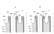
- a stub 22 protruding into the outlet-side water chamber 14 is formed integrally with the outlet-side tube sheet 11a.
- Ends of the heat transfer tubes 12 are inserted into the holes and stubs 22 formed in the tube plate 11a on the outlet side, and the required portions of the heat transfer tubes 12 are expanded by a well-known tube expansion device. It adheres and is fixed to the inner surface of each hole drilled in the plate 11a. In some cases, each heat transfer tube 12 is not expanded.
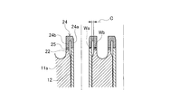
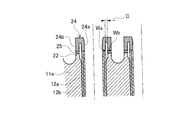
- a ring-shaped end piece 24 is connected to the end surface of each stub 22 and each heat transfer tube 12.
- the inner diameter of the stub 22 is set slightly larger than the outer diameter of the heat transfer tube 12, and a predetermined clearance C is provided between the inner peripheral surface of the stub 22 and the outer peripheral surface of the end portion of the heat transfer tube 12.
- the end piece 24 is formed into a grooved (channel type) having an arc-shaped groove bottom, and the end surface (inner end surface) of the inner cylindrical portion 24a is the end surface of the heat transfer tube 12, and the end surface of the outer cylindrical portion 24b ( The outer end surface) is butt welded to the end surface of the stub 22.
- the ring-shaped end piece 24 is formed with a groove having a bottom having an arcuate vertical cross section and opened on one end surface over the entire circumference, and the inner cylindrical portion positioned on the inner side with the groove as a boundary.
- the end surface (inner end surface) of 24 a is butt welded to the end surface of the heat transfer tube 12, and the end surface (outer end surface) of the outer cylindrical portion 24 b positioned outside the groove is butt welded to the end surface of the stub 22.
- the tube plate 11a on the outlet side, the heat transfer tube 12, and the end piece 24 are made of the same material such as ferritic steel, so that the inner welded portion Wa and the outer welded portion Wb have the same welded portion height.
- Direct butt welding At this time, since the inner welded portion Wa and the outer welded portion Wb have the same welded portion height, one pass from the inner surface side of the inner tube portion 24a of the heat transfer tube 12 and the end piece 24 that easily secures a welding work space.
- the welded portion height of the inner welded portion Wa (the inner end surface of the end piece 24) and the outer welded portion Wb (the outer end surface of the endpiece 24) are made different, The clearance C may be more reliably maintained by welding individually from the outside.
- 3A shows the case where the inner end surface of the end piece 24 is higher than the outer end surface (positioned on the upper side in FIG. 3A)
- FIG. 3B shows the inner end surface of the end piece 24 lower than the outer end surface (the lower side in FIG. 3B). Position).
- the clearance C is appropriately set according to conditions such as that the beads do not adhere to each other in the inner welded portion Wa and the outer welded portion Wb, or the tube pitch setting in the heat transfer tube 12.
- the end piece 24 has an outer diameter that substantially matches the outer diameter of the stub 22, and an inner diameter that substantially matches the inner diameter of the heat transfer tube 12.
- the heat exchanger 10 configured as described above has a cylindrical shape projecting toward the outlet side and inlet side tube plates 11a and 11b and the outlet side and inlet side water chambers 14 and 15 of the tube plates 11a and 11b.
- a clearance C is provided in the stub 22 between the end outer peripheral surface of each heat transfer tube 12 and the inner peripheral surface of the stub 22 by making the inner diameter of the stub 22 slightly larger than the outer diameter of the heat transfer tube 12.
- the end surfaces of the inner cylindrical portion 24a and the outer cylindrical portion 24b of the ring-shaped grooved end piece 24 are arranged on the end surfaces of the heat transfer tube 12 and the stub 22, and the end surfaces of the outer cylindrical portion 24b are arranged on the end surface of the stub 22 and on the inner side.
- the cylindrical portion 24a is manufactured by butt welding each corresponding to the end surface of the heat transfer tube 12.
- the clearance C is provided between the inner peripheral surface of the stub 22 of the tube plates 11a and 11b on the outlet side and the inlet side and the outer peripheral surface of the end portion of the heat transfer tube 12, and the heat transfer tube Since the end surfaces of the inner cylindrical portion 24a and the outer cylindrical portion 24b of the end piece 24 are butt welded to the end surfaces of the stub 22 and the stub 22, the respective joint portions of the heat transfer tube 12 and the stub 22 (the inner welded portion Wa and the outer portion). The structural discontinuity of the welded portion Wb) can be reduced, and the stress concentration in the welded portion under the operation of the equipment can be effectively reduced to increase the reliability.
- the inner welded portion Wa and the outer welded portion Wb are joined with the same welded portion height, it is possible to perform laser welding in one pass from the inner surface side of the heat transfer tube 12 and the number of manufacturing steps is greatly increased.
- the device can be made compact by reducing the pipe pitch.
- FIG. 4 is an enlarged detail view of the portion A of FIG. 1 showing the second embodiment of the present invention
- FIG. 5 is an enlarged detail view of the portion A showing a modified example of the height of the welded portion
- FIG. FIG. 5B shows a case where the inner end surface of the end piece is lower than the outer end surface (located on the lower side in FIG. 5B) when it is higher than the end surface (located on the upper side in FIG. 5A).
- the end piece 24 is made of the same material as the heat transfer tube 12 made of Inconel or the like.
- the end surface of the outer cylindrical portion 24b is butt-welded to the end surface of the stub 22 made of ferritic steel or the like in which the build-up weld portion 25 is previously formed of the same material as the end piece 24. Since the other configuration is the same as that of the first embodiment, the same members and parts as those in FIG.
- the welded portion heights of the inner welded portion Wa (the inner end surface of the end piece 24) and the outer welded portion Wb (the outer end surface of the endpiece 24) are made different.
- the clearance C may be more reliably maintained by welding each part individually from the inside and the outside.
- 5A shows the case where the inner end surface of the end piece 24 is higher than the outer end surface (located on the upper side in FIG. 5A)
- FIG. 5B shows the inner end surface of the end piece 24 lower than the outer end surface (lower in FIG. 5B). Position).
- FIG. 6 is an enlarged detail view of part A of FIG. 1 showing Embodiment 3 of the present invention
- FIG. 7 is an enlarged detail view of part A of FIG. 1 showing an example of a change in the weld height
- FIG. FIG. 7B shows a case where the end face is higher than the outer end face (located on the upper side in FIG. 7A)
- FIG. 7B shows a case where the inner end face of the end piece is lower than the outer end face (located on the lower side in FIG. 7B).
- the heat transfer tube 12 is a double tube (multiple tube) composed of an outer heat transfer tube 12a and an inner heat transfer tube 12b. Since the other configuration is the same as that of the first embodiment, the same members and parts as those in FIG.
- the welded portion heights of the inner welded portion Wa (the inner end surface of the end piece 24) and the outer welded portion Wb (the outer end surface of the endpiece 24) are made different.
- the clearance C may be more reliably maintained by welding each part individually from the inside and the outside.
- 7A shows a case where the inner end surface of the end piece 24 is higher than the outer end surface (positioned upward in FIG. 7A)
- FIG. 7B shows that the inner end surface of the end piece 24 is lower than the outer end surface (lower side in FIG. 7B). Position).
- the boundary between the heated fluid (medium) and the heated fluid (medium) can be strengthened by the double-tube heat transfer tubes 12a and 12b. Is obtained.
- FIG. 8 is an enlarged detail view of part A of FIG. 1 showing Embodiment 4 of the present invention
- FIG. 9 is an enlarged detail view of part A of FIG. 9B shows a case where the end face is higher than the outer end face (located on the upper side in FIG. 9A)
- FIG. 9B shows a case where the inner end face of the end piece is lower than the outer end face (located on the lower side in FIG. 9B).
- the heat transfer tube 12 is a double tube (multiple tube) including an outer heat transfer tube 12a and an inner heat transfer tube 12b. Since other configurations are the same as those in the second embodiment, the same members and portions as those in FIG.
- the welded portion heights of the inner welded portion Wa (the inner end surface of the end piece 24) and the outer welded portion Wb (the outer end surface of the endpiece 24) are made different.
- the clearance C may be more reliably maintained by welding each part individually from the inside and the outside.
- 9A shows the case where the inner end surface of the end piece 24 is higher than the outer end surface (positioned upward in FIG. 9A)
- FIG. 9B shows the inner end surface of the end piece 24 lower than the outer end surface (lower side in FIG. 9B). Position).
- the boundary between the heated fluid (medium) and the heated fluid (medium) can be strengthened by the double-tube heat transfer tubes 12a and 12b. Is obtained.
- the present invention is not limited to the above embodiments, and various modifications can be made without departing from the scope of the present invention.
- the clearance C is provided by expanding the diameter of the stub 22 side, but the diameter of the heat transfer tube 12 is reduced, or both the stub 22 and the heat transfer tube 12 are processed. You may do it.
- the heat exchanger and the heat exchanger manufacturing method according to the present invention are suitable for application to steam generators, heaters, superheaters, water heaters, coolers, condensers, and the like.
Abstract
A clearance (C) is provided between the inner circumferential surface of cylindrical stubs (22) (which protrude toward the outlet-side and inlet-side water chambers (14, 15) of outlet-side and inlet-side tube plates (11a, 11b)) and the outer circumferential surface at the end part of heat transfer tubes (12) inserted into the stubs (22), and the end faces of the inside tube parts (24a) and the outside tube parts (24b) of grooved end pieces (24) are laser-welded to the end faces of the heat transfer tubes (12) and the stubs (22) from the inner-surface side of the heat transfer tube (12), with the weld height of the end faces of the outside tube parts (24b) and the end faces of the stubs (22) and the weld height of the end faces of the inside tube parts (24a) and the end faces of the heat transfer tubes (12) corresponding to each other, thereby enabling butt-welding to be performed in one pass.
Description
本発明は、温度の異なる流体の間接的な接触によって熱交換を行うシェル・アンド・チューブ型の熱交換器及び熱交換器の製造方法に関するものである。
The present invention relates to a shell-and-tube heat exchanger that performs heat exchange by indirect contact of fluids having different temperatures, and a method for manufacturing the heat exchanger.
シェル・アンド・チューブ型の多管式熱交換器として、従来、図10乃至図12に示すような管‐管板継手構造を有したものが特許文献1で開示されている。
Conventionally, as a shell-and-tube type multi-tube heat exchanger, one having a tube-tube plate joint structure as shown in FIGS. 10 to 12 is disclosed in Patent Document 1.
図10に示すものは、管板100の表面(水室101側の面)に、短管状で且つ伝熱管102が貫通可能な管台103を溶接し、該管台103と管板100に対し伝熱管102の端部を貫通させて管台103の先端から所要量だけ突出させるようにし、該伝熱管102の管台103からの突出部外周を管台103の先端に溶接するように構成したものである。具体的には、管板100及び管台103に伝熱管102を通過させ、伝熱管102を拡管処理により管板100(の孔内面)に密着・固定した後、管台103の端部全周を伝熱管102の外周面に溶接し、隅肉溶接部104を形成している。
10 is welded to the surface of the tube plate 100 (the surface on the water chamber 101 side) a tube base 103 that is short tubular and through which the heat transfer tube 102 can pass, and is attached to the tube plate 103 and the tube plate 100. The end of the heat transfer tube 102 is penetrated so as to protrude from the tip of the nozzle pedestal 103 by a required amount, and the outer periphery of the protruding portion of the heat transfer tube 102 from the nozzle pedestal 103 is welded to the tip of the nozzle pedestal 103. Is. Specifically, after the heat transfer tube 102 is passed through the tube plate 100 and the nozzle pedestal 103 and the heat transfer tube 102 is closely attached and fixed to the tube plate 100 (the inner surface of the hole) by the tube expansion process, the entire circumference of the end of the tube pedestal 103 is obtained. Is welded to the outer peripheral surface of the heat transfer tube 102 to form a fillet welded portion 104.
図11に示すものは、管板100に穿設された孔の水室101側に位置した周縁にスタブ105を一体形成し、該管板100に穿設された孔及びスタブ105に伝熱管102の端部をスタブ105と同一高さまで挿入した後、伝熱管102を拡管処理により管板100(の孔内面)に密着・固定する。そして、管板100及びスタブ105と伝熱管102との液密性を高めるために、スタブ105と伝熱管102の端面にはリング状のエンドピース106が付き合わされて連接され、スタブ105、伝熱管102及びエンドピース106の突き合わされた開先部に全周囲に亘ってTig溶接等により肉盛溶接部107を形成するように構成したものである。
In FIG. 11, a stub 105 is integrally formed at the periphery of the hole formed in the tube plate 100 on the water chamber 101 side, and the heat transfer tube 102 is formed in the hole and stub 105 formed in the tube plate 100. Then, the heat transfer tube 102 is closely attached to and fixed to the tube plate 100 (the inner surface of the hole) by the tube expansion process. In order to improve the liquid tightness between the tube plate 100 and the stub 105 and the heat transfer tube 102, a ring-shaped end piece 106 is attached to and connected to the end surfaces of the stub 105 and the heat transfer tube 102. The build-up welded portion 107 is formed by Tig welding or the like around the entire periphery of the groove portion where the end face 106 and the end piece 106 are abutted.
図12に示すものは、図11に示す管‐管板継手構造における加熱流体(媒体)と被加熱流体(媒体)とのバウンダリを強化するために、図11における伝熱管102を外側伝熱管102aと内側伝熱管102bとの二重管に構成したものであり、その他の構成は図11と同様なので図11と同一部材には同一符号を付して重複する説明は省略する。
In order to reinforce the boundary between the heated fluid (medium) and the heated fluid (medium) in the tube-tube plate joint structure shown in FIG. 11, the heat transfer tube 102 shown in FIG. 11 is replaced with the outer heat transfer tube 102a. 11 and the inner heat transfer tube 102b, and the other configurations are the same as those in FIG. 11, and thus the same members as those in FIG.
しかしながら、図10に示す管‐管板継手構造にあっては、管板100の孔に伝熱管102を挿入し、水室側から伝熱管102と管板100を溶接して隅肉溶接部104を形成するので製作性に優れるという利点があるが、隅肉溶接部104周辺で肉厚が変化するため放射線透過検査(RT検査)などの体積検査が困難であると共に、機器の運転下で伝熱管102と管台100の接合部に荷重が負荷された場合には当該接合部の不連続性(母材同士が一体化しない)により継手部への応力集中が高くなって信頼性が低下するという不具合があった。
However, in the tube-tube plate joint structure shown in FIG. 10, the heat transfer tube 102 is inserted into the hole of the tube plate 100, and the heat transfer tube 102 and the tube plate 100 are welded from the water chamber side to fillet welded portions 104. However, since the thickness changes around the fillet weld 104, volume inspection such as radiographic inspection (RT inspection) is difficult, and transmission is performed under equipment operation. When a load is applied to the joint between the heat pipe 102 and the nozzle 100, the discontinuity of the joint (the base materials are not integrated with each other) increases the stress concentration on the joint and reduces the reliability. There was a malfunction.
また、図11及び図12に示す管‐管板継手構造にあっては、管板100の孔に伝熱管102を挿入し、水室側からスタブ105、伝熱管102(外側伝熱管102a,内側伝熱管102b)及びエンドピース106の突き合わされた開先部に肉盛溶接部107を形成するので、図10に示すものと同様に、製作性に優れると共に、肉盛溶接部107周辺で肉厚が変化しないため放射線透過検査(RT検査)などの体積検査が可能となる利点があるが、機器の運転下で伝熱管102(外側伝熱管102a,内側伝熱管102b)及び管台100とエンドピース106の接合部に荷重が負荷された場合には当該接合部の構造不連続性(母材同士が一体化しない)により継手部への応力集中が高くなって、図10に示すものと同様に、信頼性が低下するという不具合があった。
Further, in the tube-tube plate joint structure shown in FIGS. 11 and 12, the heat transfer tube 102 is inserted into the hole of the tube plate 100, and the stub 105, the heat transfer tube 102 (the outer heat transfer tube 102a, the inner side) are inserted from the water chamber side. Since the weld weld 107 is formed in the groove portion where the heat transfer tube 102b) and the end piece 106 are abutted with each other, it is excellent in manufacturability and thick in the vicinity of the weld overlay 107 as shown in FIG. Since there is no change, there is an advantage that volume inspection such as radiographic inspection (RT inspection) is possible. However, the heat transfer tube 102 (outer heat transfer tube 102a, inner heat transfer tube 102b), the nozzle 100 and the end piece are operated under the operation of the equipment. When a load is applied to the joint portion of 106, the stress concentration on the joint portion increases due to the structural discontinuity of the joint portion (the base materials are not integrated with each other), and the same as shown in FIG. , Reliable There is a problem that is under.
本発明は、このような実情を鑑み提案されたもので、製作容易性と検査容易性を維持しつつ機器の運転下における溶接部の応力集中を効果的に低減して信頼性を高められる熱交換器及び熱交換器の製造方法を提供することを目的とする。
The present invention has been proposed in view of such circumstances, and it is possible to effectively reduce the stress concentration in the welded part under the operation of the equipment while maintaining the ease of manufacture and inspection, and to improve the reliability. It aims at providing the manufacturing method of an exchanger and a heat exchanger.
斯かる目的を達成するための本発明に係る熱交換器は、
管板間に伝熱管が設けられた熱交換器において、
前記管板の水室側へ突出した円筒状のスタブの内周面と当該スタブ内に挿入される伝熱管端部の外周面との間にクリアランスを設け、
前記伝熱管及びスタブの端面にリング状の溝付きエンドピースの内側及び外側端面を、当該外側端面をスタブの端面に且つ内側端面を伝熱管の端面にそれぞれ対応させて、突合せ溶接してなることを特徴とする。 In order to achieve such an object, the heat exchanger according to the present invention comprises:
In a heat exchanger in which a heat transfer tube is provided between tube plates,
A clearance is provided between the inner peripheral surface of the cylindrical stub protruding to the water chamber side of the tube sheet and the outer peripheral surface of the end portion of the heat transfer tube inserted into the stub,
The inner and outer end faces of the ring-shaped grooved end piece are attached to the end faces of the heat transfer tube and the stub, the outer end face corresponds to the end face of the stub, and the inner end face corresponds to the end face of the heat transfer pipe. It is characterized by.
前記管板と伝熱管の材質が同じである場合、これらと同じ材質のエンドピースの内側及び外側端面が伝熱管及びスタブの端面に直接接合してなることを特徴とする。
When the tube plate and the heat transfer tube are made of the same material, the inner and outer end surfaces of the end pieces of the same material are directly joined to the end surfaces of the heat transfer tube and the stub.
前記管板と伝熱管の材質が異なる場合、伝熱管と同じ材質のエンドピースの外側端面を、予めエンドピースと同じ材質で肉盛溶接部が形成された前記スタブの端面に接合してなることを特徴とする。
When the tube plate and the heat transfer tube are made of different materials, the outer end surface of the end piece made of the same material as the heat transfer tube is joined to the end surface of the stub in which the build-up weld is formed in advance using the same material as the end piece. It is characterized by.
前記エンドピースの内側及び外側端面の溶接部高さが同じであることを特徴とする。
The welded portion height of the inner end surface and the outer end surface of the end piece is the same.
前記エンドピースの内側及び外側端面の溶接部高さが異なっていることを特徴とする。
溶 接 The height of the welded portion on the inner and outer end faces of the end piece is different.
前記伝熱管は多重管であることを特徴とする。
The heat transfer tube is a multiple tube.
斯かる目的を達成するための本発明に係る熱交換器の製造方法は、
管板間に多数の伝熱管が設けられた熱交換器の製造方法において、
前記管板及び前記管板の水室側へ多数突出した円筒状のスタブ内に各伝熱管をその端部外周面と前記スタブ内周面との間にクリアランスを設けて挿入した後、
前記伝熱管及びスタブの端面にリング状の溝付きエンドピースの内側及び外側端面を、当該外側端面をスタブの端面に且つ内側端面を伝熱管の端面に対応させて、それぞれ突合せ溶接することを特徴とする。 A method for manufacturing a heat exchanger according to the present invention for achieving such an object,
In a method for manufacturing a heat exchanger in which a large number of heat transfer tubes are provided between tube plates,
After inserting each heat transfer tube into a cylindrical stub projecting toward the water chamber side of the tube plate and the tube plate with a clearance between the outer peripheral surface of the end portion and the inner peripheral surface of the stub,
The end faces of the heat transfer tubes and stubs are butt welded with the inner and outer end faces of the ring-shaped grooved end piece, the outer end faces corresponding to the end faces of the stubs, and the inner end faces corresponding to the end faces of the heat transfer tubes. And
前記管板と伝熱管の材質が同じである場合、これらと同じ材質のエンドピースの内側及び外側端面を伝熱管及びスタブの端面に直接接合することを特徴とする。
When the tube plate and the heat transfer tube are made of the same material, the inner and outer end surfaces of the end pieces of the same material are directly joined to the end surfaces of the heat transfer tube and the stub.
前記管板と伝熱管の材質が異なる場合、伝熱管と同じ材質のエンドピースの外側端面を、予めエンドピースと同じ材質で肉盛溶接部が形成された前記スタブの端面に接合することを特徴とする。
When the tube plate and the heat transfer tube are made of different materials, the outer end surface of the end piece made of the same material as the heat transfer tube is joined to the end surface of the stub in which the build-up weld is formed in advance by the same material as the end piece. And
前記エンドピースの内側及び外側端面を同じ溶接部高さで接合することを特徴とする。
The inner and outer end faces of the end piece are joined at the same weld height.
前記エンドピースの内側及び外側端面を異なった溶接部高さで接合することを特徴とする。
The inner and outer end faces of the end piece are joined at different weld heights.
前記伝熱管に多重管を用いることを特徴とする。
The heat transfer tube is characterized by using a multiple tube.
本発明に係る熱交換器及び熱交換器の製造方法によれば、管板のスタブの内周面と伝熱管端部の外周面との間にクリアランスを設け、伝熱管及びスタブの端面にエンドピースの内側及び外側端面を突合せ溶接することで、伝熱管とスタブのそれぞれの接合部の構造不連続を低減でき、機器の運転下における溶接部の応力集中を効果的に低減して信頼性を高められる。加えて、水室側からの溶接により製作性を確保できると共に、溶接部の肉厚変化をなくして放射線透過検査(RT検査)などの体積検査が可能となる。
According to the heat exchanger and the method of manufacturing a heat exchanger according to the present invention, a clearance is provided between the inner peripheral surface of the stub of the tube sheet and the outer peripheral surface of the end portion of the heat transfer tube, and ends on the end surfaces of the heat transfer tube and the stub. By butt welding the inner and outer end faces of the piece, it is possible to reduce structural discontinuities at the joints of the heat transfer tubes and stubs, effectively reducing the stress concentration in the welds during the operation of the equipment and increasing reliability. Enhanced. In addition, manufacturability can be ensured by welding from the water chamber side, and volume inspection such as radiographic inspection (RT inspection) can be performed without changing the thickness of the welded portion.
また、管板と伝熱管の材質が同じである場合、これらと同じ材質のエンドピースの内側及び外側端面が伝熱管及びスタブの端面に直接接合することで、溶接作業を迅速に行える。
Also, when the material of the tube plate and the heat transfer tube are the same, the inner and outer end surfaces of the same material end pieces are directly joined to the end surfaces of the heat transfer tube and the stub, so that the welding operation can be performed quickly.
また、管板と伝熱管の材質が異なる場合、伝熱管と同じ材質のエンドピースの外側端面を、予めエンドピースと同じ材質で肉盛溶接部が形成された前記スタブの端面に接合することで、異材間接合が可能となり、異材溶接部への熱衝撃も低減できる。
Moreover, when the material of the tube plate and the heat transfer tube are different, the outer end surface of the end piece made of the same material as the heat transfer tube is joined to the end surface of the stub in which the build-up weld is formed in advance with the same material as the end piece. This makes it possible to join different materials and to reduce the thermal shock to the welded portion of the different materials.
また、エンドピースの内側及び外側端面の溶接部高さが同じであると、エンドピースの内面側又は外面側から1パスでレーザ溶接することが可能となり、製作工数を大幅に低減できる。また、エンドピースの内面側から溶接することで、管ピッチ縮小により、機器のコンパクト化が可能となる。
Also, if the welded part heights on the inner and outer end surfaces of the end piece are the same, laser welding can be performed in one pass from the inner surface side or outer surface side of the end piece, and the number of manufacturing steps can be greatly reduced. Further, by welding from the inner surface side of the end piece, the equipment can be made compact by reducing the pipe pitch.
また、エンドピースの内側及び外側端面の溶接部高さが異なっていると、エンドピースの内面側及び外面側から個別に溶接することが可能となり、クリアランスを確実に維持したまま溶接することができる。
In addition, if the welded part heights of the inner and outer end faces of the end piece are different, it is possible to weld individually from the inner surface side and the outer surface side of the end piece, and welding can be performed while maintaining the clearance reliably. .
また、伝熱管は単管でも良いが、多重管であることで、加熱流体(媒体)と被加熱流体(媒体)とのバウンダリの強化が図れる。
Also, the heat transfer tube may be a single tube, but by using multiple tubes, the boundary between the heated fluid (medium) and the heated fluid (medium) can be strengthened.
以下、本発明に係る熱交換器及び熱交換器の製造方法を実施例により図面を用いて詳細に説明する。
Hereinafter, the heat exchanger and the method for manufacturing the heat exchanger according to the present invention will be described in detail with reference to the drawings by way of examples.
図1は本発明の実施例1を示す熱交換器の全体構成縦断面図、図2は同じく図1のA部拡大詳細図、図3は同じく溶接部高さの変更例を示す図1のA部拡大詳細図で、図3Aはエンドピースの内側端面が外側端面より高い(図3Aにおいて上方側に位置する)場合で、図3Bはエンドピースの内側端面が外側端面より低い(図3Bにおいて下方側に位置する)場合を示す。
1 is a longitudinal sectional view of the overall configuration of a heat exchanger showing Embodiment 1 of the present invention, FIG. 2 is an enlarged detail view of part A of FIG. 1, and FIG. 3A is an enlarged detail view of FIG. 3A, in which FIG. 3A shows a case where the inner end surface of the end piece is higher than the outer end surface (positioned upward in FIG. 3A), and FIG. 3B shows that the inner end surface of the end piece is lower than the outer end surface. The case is located on the lower side).
図1に示すように、本実施例の熱交換器10は、上,下両管板11a,11b間に多数の伝熱管12が設けられたシェル・アンド・チューブ型の多管式熱交換器である。加熱流体(媒体)としては、熱水、ボイラ等における火炎、高温気体、高温蒸気、原子力発電設備における液体金属ナトリウム、等が用いられ、被加熱流体(媒体)としては、水、蒸気、反応のために加熱する化学物質(流体)等が用いられる。
As shown in FIG. 1, a heat exchanger 10 of this embodiment is a shell-and-tube type multi-tube heat exchanger in which a large number of heat transfer tubes 12 are provided between upper and lower tube plates 11a and 11b. It is. As the heating fluid (medium), flames in hot water, boilers, etc., high temperature gas, high temperature steam, liquid metal sodium in nuclear power generation facilities, etc. are used, and as the heated fluid (medium), water, steam, reaction For this purpose, a heated chemical substance (fluid) or the like is used.
具体的には、熱交換器10は、中央部の胴部13、胴部13の上端に気密或いは液密に取り付けられた上部の出口側の管板11a及び上部の出口側の水室14(又は、仕切り室、プレナム、ヘッダー、マニホールドともいう)、胴部13の下端に液密に取り付けられた下部の入口側の管板11b及び下部の入口側の水室15(又は、仕切り室、プレナム、ヘッダー、マニホールドともいう)により構成されている。
Specifically, the heat exchanger 10 includes a central barrel 13, an upper outlet-side tube sheet 11 a attached to the upper end of the barrel 13 in an airtight or liquid-tight manner, and an upper outlet-side water chamber 14 ( Or a partition chamber, a plenum, a header, or a manifold), a lower inlet-side tube plate 11 b and a lower inlet-side water chamber 15 (or a partition chamber, a plenum) attached to the lower end of the body portion 13. , Header, and manifold).
入口側の水室15には、被加熱流体(媒体)16を導入する被加熱流体(媒体)導入管17が接続され、出口側の水室14には、被加熱流体(媒体)排出管18が接続されている。また、胴部13の一方下端部には、加熱流体(媒体)19を導入する加熱流体(媒体)導入管20が接続され、胴部13の他方上端部には、加熱流体(媒体)排出管21が接続されている。
A heated fluid (medium) introduction pipe 17 for introducing a heated fluid (medium) 16 is connected to the water chamber 15 on the inlet side, and a heated fluid (medium) discharge pipe 18 is connected to the water chamber 14 on the outlet side. Is connected. Further, a heating fluid (medium) introduction pipe 20 for introducing a heating fluid (medium) 19 is connected to one lower end portion of the body portion 13, and a heating fluid (medium) discharge pipe is connected to the other upper end portion of the body portion 13. 21 is connected.
胴部13内には、多数(図示例では便宜上2本)の伝熱管12が配設されており、この各伝熱管12の上端は、出口側の管板11aに穿設された孔及び後述するスタブ22(図2参照)を貫通し出口側の水室14内に突出している。また、各伝熱管12の下端も同様に、入口側の管板11bに穿設された孔及び図示しないスタブを貫通し入口側の水室15内に突出している。そして、スタブ22及び伝熱管12の全ての両端には、後述するエンドピース24(図2参照)が溶接により接合されている。
A large number (two for convenience in the illustrated example) of heat transfer tubes 12 are arranged in the body portion 13, and an upper end of each heat transfer tube 12 is formed with a hole formed in the tube plate 11 a on the outlet side and a later-described tube. Through the stub 22 (see FIG. 2), and protrudes into the water chamber 14 on the outlet side. Similarly, the lower ends of the heat transfer tubes 12 pass through holes formed in the tube plate 11b on the inlet side and stubs (not shown) and project into the water chamber 15 on the inlet side. And the end piece 24 (refer FIG. 2) mentioned later is joined to all the both ends of the stub 22 and the heat exchanger tube 12 by welding.
上述した熱交換器10において、加熱流体(媒体)19は、加熱流体(媒体)導入管20から胴部13内に導入されて、伝熱管12内の被加熱流体(媒体)16を加熱した後、加熱流体(媒体)排出管21から排出される。また、被加熱流体16は、被加熱流体(媒体)導入管17から入口側の水室15に導入され、多数の伝熱管12を流れながら加熱流体(媒体)19により加熱された後、出口側の水室14を通り被加熱流体(媒体)排出管18から排出される。
In the heat exchanger 10 described above, the heating fluid (medium) 19 is introduced from the heating fluid (medium) introduction pipe 20 into the body portion 13 to heat the heated fluid (medium) 16 in the heat transfer pipe 12. The heated fluid (medium) discharge pipe 21 is discharged. The heated fluid 16 is introduced from the heated fluid (medium) introduction pipe 17 to the water chamber 15 on the inlet side, heated by the heated fluid (medium) 19 while flowing through the heat transfer pipes 12, and then the outlet side. It passes through the water chamber 14 and is discharged from the heated fluid (medium) discharge pipe 18.
尚、図1に示す伝熱管12は、直管からなる1重管(単管)型の例を示しているが、これに限定されるものではなく、U字管型、ヘリカルコイル型、多重管型(2重管以上のもの)等、各種の形状のものとすることができる。また、図1中23はバッフルプレートである。
The heat transfer tube 12 shown in FIG. 1 shows an example of a single tube (single tube) type made of a straight tube, but is not limited to this, and is not limited to this, a U-shaped tube type, a helical coil type, a multiple tube type. It can be of various shapes such as a tube type (one having a double tube or more). In FIG. 1, reference numeral 23 denotes a baffle plate.
次に、図2に基づき、図1のA部における管‐管板継手構造を説明する。尚、図1のB部における管‐管板継手構造も同じ構造であるので、ここでは図2を参照して重複する説明は省略する。
Next, the tube-tube sheet joint structure in part A of FIG. 1 will be described based on FIG. Since the tube-tube plate joint structure in part B of FIG. 1 is also the same structure, redundant description is omitted here with reference to FIG.
上述のごとく、出口側の管板11aには、各伝熱管12を通すための多数の孔が穿設される。この各孔の周囲には、出口側の水室14に突出したスタブ22が、出口側の管板11aに一体形成される。
As described above, a large number of holes for passing the heat transfer tubes 12 are formed in the tube plate 11a on the outlet side. Around each hole, a stub 22 protruding into the outlet-side water chamber 14 is formed integrally with the outlet-side tube sheet 11a.
そして、出口側の管板11aに穿設された孔及びスタブ22には各々伝熱管12の端部が挿入され、各伝熱管12は周知の拡管装置により所要部が拡張されて出口側の管板11aに穿設された各孔の内面に密着・固定される。尚、各伝熱管12を拡管しない場合も有る。
Ends of the heat transfer tubes 12 are inserted into the holes and stubs 22 formed in the tube plate 11a on the outlet side, and the required portions of the heat transfer tubes 12 are expanded by a well-known tube expansion device. It adheres and is fixed to the inner surface of each hole drilled in the plate 11a. In some cases, each heat transfer tube 12 is not expanded.
更に、本実施例においては、出口側の管板11a或いはスタブ22と伝熱管12との荷重を受け持つために、各スタブ22及び各伝熱管12の端面にはリング状のエンドピース24が連接される。
Furthermore, in this embodiment, in order to handle the load between the tube sheet 11a or the stub 22 on the outlet side and the heat transfer tube 12, a ring-shaped end piece 24 is connected to the end surface of each stub 22 and each heat transfer tube 12. The
詳細には、先ず、スタブ22の内径が伝熱管12の外径よりやや大きく設定されてスタブ22の内周面と伝熱管12の端部外周面との間に所定のクリアランスCが設けられる。そして、エンドピース24は円弧状の溝底を有する溝付き(チャネル型)に形成されてその内側筒部24aの端面(内側端面)が伝熱管12の端面に、また外側筒部24bの端面(外側端面)がスタブ22の端面に、それぞれ突合せ溶接される。つまり、リング状のエンドピース24には、縦断面が円弧状となる底を有して一端面に開口する溝が全周に亘って形成され、当該溝を境として内側に位置する内側筒部24aの端面(内側端面)が伝熱管12の端面に突合せ溶接されると共に、前記溝を境として外側に位置する外側筒部24bの端面(外側端面)がスタブ22の端面に突合せ溶接される。
Specifically, first, the inner diameter of the stub 22 is set slightly larger than the outer diameter of the heat transfer tube 12, and a predetermined clearance C is provided between the inner peripheral surface of the stub 22 and the outer peripheral surface of the end portion of the heat transfer tube 12. The end piece 24 is formed into a grooved (channel type) having an arc-shaped groove bottom, and the end surface (inner end surface) of the inner cylindrical portion 24a is the end surface of the heat transfer tube 12, and the end surface of the outer cylindrical portion 24b ( The outer end surface) is butt welded to the end surface of the stub 22. That is, the ring-shaped end piece 24 is formed with a groove having a bottom having an arcuate vertical cross section and opened on one end surface over the entire circumference, and the inner cylindrical portion positioned on the inner side with the groove as a boundary. The end surface (inner end surface) of 24 a is butt welded to the end surface of the heat transfer tube 12, and the end surface (outer end surface) of the outer cylindrical portion 24 b positioned outside the groove is butt welded to the end surface of the stub 22.
図示例では、出口側の管板11aと伝熱管12とエンドピース24とがフェライト鋼等の同一の材質であることから、内側の溶接部Waと外側の溶接部Wbが同じ溶接部高さで直接突合せ溶接されている。この際、内側の溶接部Waと外側の溶接部Wbが同じ溶接部高さであることから、溶接作業スペースを確保し易い伝熱管12及びエンドピース24の内側筒部24aの内面側から1パスでレーザ溶接することが可能である。勿論、伝熱管12及びエンドピース24の外側筒部24bの外面側から1パスでレーザ溶接しても良い。
In the illustrated example, the tube plate 11a on the outlet side, the heat transfer tube 12, and the end piece 24 are made of the same material such as ferritic steel, so that the inner welded portion Wa and the outer welded portion Wb have the same welded portion height. Direct butt welding. At this time, since the inner welded portion Wa and the outer welded portion Wb have the same welded portion height, one pass from the inner surface side of the inner tube portion 24a of the heat transfer tube 12 and the end piece 24 that easily secures a welding work space. Can be laser welded. Of course, laser welding may be performed in one pass from the outer surface side of the outer tube portion 24b of the heat transfer tube 12 and the end piece 24.
また、図3に示すように、内側の溶接部Wa(エンドピース24の内側端面)と外側の溶接部Wb(エンドピース24の外側端面)の溶接部高さを異ならせて、各部を内、外から個別に溶接することで、クリアランスCをより確実に維持できるようにしても良い。尚、図3Aはエンドピース24の内側端面が外側端面より高い(図3Aにおいて上方側に位置する)場合で、図3Bはエンドピース24の内側端面が外側端面より低い(図3Bにおいて下方側に位置する)場合を示す。
Further, as shown in FIG. 3, the welded portion height of the inner welded portion Wa (the inner end surface of the end piece 24) and the outer welded portion Wb (the outer end surface of the endpiece 24) are made different, The clearance C may be more reliably maintained by welding individually from the outside. 3A shows the case where the inner end surface of the end piece 24 is higher than the outer end surface (positioned on the upper side in FIG. 3A), and FIG. 3B shows the inner end surface of the end piece 24 lower than the outer end surface (the lower side in FIG. 3B). Position).
前記クリアランスCは、内側の溶接部Waと外側の溶接部Wbにおいてビード同士が接着しないこととか伝熱管12における管ピッチ設定等の条件に応じて適宜設定される。また、エンドピース24は、その外径がスタブ22の外径とほぼ一致し、内径が伝熱管12の内径とほぼ一致するものとなっている。
The clearance C is appropriately set according to conditions such as that the beads do not adhere to each other in the inner welded portion Wa and the outer welded portion Wb, or the tube pitch setting in the heat transfer tube 12. The end piece 24 has an outer diameter that substantially matches the outer diameter of the stub 22, and an inner diameter that substantially matches the inner diameter of the heat transfer tube 12.
このように構成される熱交換器10は、出口側及び入口側の管板11a,11bと当該管板11a,11bの出口側及び入口側の水室14,15側へ多数突出した円筒状のスタブ22内に各伝熱管12をその端部外周面とスタブ22の内周面との間に、スタブ22の内径を伝熱管12の外径よりやや大きくするなどして、クリアランスCを設けて挿入した後、伝熱管12及びスタブ22の端面にリング状の溝付きエンドピース24における内側筒部24a及び外側筒部24bの端面を、当該外側筒部24bの端面をスタブ22の端面に且つ内側筒部24aの端面を伝熱管12の端面に対応させて、それぞれ突合せ溶接することで製造される。
The heat exchanger 10 configured as described above has a cylindrical shape projecting toward the outlet side and inlet side tube plates 11a and 11b and the outlet side and inlet side water chambers 14 and 15 of the tube plates 11a and 11b. A clearance C is provided in the stub 22 between the end outer peripheral surface of each heat transfer tube 12 and the inner peripheral surface of the stub 22 by making the inner diameter of the stub 22 slightly larger than the outer diameter of the heat transfer tube 12. After the insertion, the end surfaces of the inner cylindrical portion 24a and the outer cylindrical portion 24b of the ring-shaped grooved end piece 24 are arranged on the end surfaces of the heat transfer tube 12 and the stub 22, and the end surfaces of the outer cylindrical portion 24b are arranged on the end surface of the stub 22 and on the inner side. The cylindrical portion 24a is manufactured by butt welding each corresponding to the end surface of the heat transfer tube 12.
この際、前記出口側及び入口側の管板11a,11bと各伝熱管12の材質が同じである場合、これらと同じ材質のエンドピース24における内側筒部24a及び外側筒部24bの端面を伝熱管12及びスタブ22の端面に内側の溶接部Waと外側の溶接部Wbの溶接部高さを同じにして直接接合することができる。
At this time, when the tube plates 11a and 11b on the outlet side and the inlet side and the heat transfer tubes 12 are made of the same material, they are transmitted through the end surfaces of the inner cylindrical portion 24a and the outer cylindrical portion 24b in the end piece 24 of the same material. It is possible to directly join the end faces of the heat pipe 12 and the stub 22 with the same welded part height of the inner welded part Wa and the outer welded part Wb.
このようにして、本実施例によれば、出口側及び入口側の管板11a,11bのスタブ22の内周面と伝熱管12の端部外周面との間にクリアランスCを設け、伝熱管12及びスタブ22の端面にエンドピース24における内側筒部24a及び外側筒部24bの端面を突合せ溶接するようにしたので、伝熱管12とスタブ22のそれぞれの接合部(内側の溶接部Waと外側の溶接部Wb参照)の構造不連続を低減でき、機器の運転下における溶接部の応力集中を効果的に低減して信頼性を高められる。加えて、出口側及び入口側の水室14,15側からの溶接により製作性を確保できると共に、接合部(内側の溶接部Waと外側の溶接部Wb参照)の肉厚変化をなくして放射線透過検査(RT検査)などの体積検査が可能となる。
Thus, according to the present embodiment, the clearance C is provided between the inner peripheral surface of the stub 22 of the tube plates 11a and 11b on the outlet side and the inlet side and the outer peripheral surface of the end portion of the heat transfer tube 12, and the heat transfer tube Since the end surfaces of the inner cylindrical portion 24a and the outer cylindrical portion 24b of the end piece 24 are butt welded to the end surfaces of the stub 22 and the stub 22, the respective joint portions of the heat transfer tube 12 and the stub 22 (the inner welded portion Wa and the outer portion). The structural discontinuity of the welded portion Wb) can be reduced, and the stress concentration in the welded portion under the operation of the equipment can be effectively reduced to increase the reliability. In addition, manufacturability can be ensured by welding from the water chambers 14 and 15 on the outlet side and the inlet side, and radiation can be eliminated without changing the wall thickness of the joint (see the inner welded portion Wa and the outer welded portion Wb). Volume inspection such as transmission inspection (RT inspection) becomes possible.
また、内側の溶接部Waと外側の溶接部Wbの溶接部高さを同じにして接合する場合は、伝熱管12の内面側などから1パスでレーザ溶接することが可能となり、製作工数は大幅に低減できると共に、管ピッチ縮小により、機器のコンパクト化が可能となる。
Further, when the inner welded portion Wa and the outer welded portion Wb are joined with the same welded portion height, it is possible to perform laser welding in one pass from the inner surface side of the heat transfer tube 12 and the number of manufacturing steps is greatly increased. The device can be made compact by reducing the pipe pitch.
図4は本発明の実施例2を示す図1のA部拡大詳細図、図5は同じく溶接部高さの変更例を示すA部拡大詳細図で、図5Aはエンドピースの内側端面が外側端面より高い(図5Aにおいて上方側に位置する)場合で、図5Bはエンドピースの内側端面が外側端面より低い(図5Bにおいて下方側に位置する)場合を示す。
4 is an enlarged detail view of the portion A of FIG. 1 showing the second embodiment of the present invention, FIG. 5 is an enlarged detail view of the portion A showing a modified example of the height of the welded portion, and FIG. FIG. 5B shows a case where the inner end surface of the end piece is lower than the outer end surface (located on the lower side in FIG. 5B) when it is higher than the end surface (located on the upper side in FIG. 5A).
これは、実施例1の管‐管板継手構造において、出口側及び入口側の管板11a,11bと伝熱管12の材質が異なる場合、インコネル等からなる伝熱管12と同じ材質のエンドピース24における外側筒部24bの端面を、予めエンドピース24と同じ材質で肉盛溶接部25が形成されたフェライト鋼等からなるスタブ22の端面に突合せ溶接するようにした例である。その他の構成は実施例1と同様なので、図2と同一部材・部位には同一符号を付して重複する説明は省略する。
This is because, in the tube-tube plate joint structure of the first embodiment, when the material of the tube plates 11a, 11b on the outlet side and the inlet side and the heat transfer tube 12 are different, the end piece 24 is made of the same material as the heat transfer tube 12 made of Inconel or the like. This is an example in which the end surface of the outer cylindrical portion 24b is butt-welded to the end surface of the stub 22 made of ferritic steel or the like in which the build-up weld portion 25 is previously formed of the same material as the end piece 24. Since the other configuration is the same as that of the first embodiment, the same members and parts as those in FIG.
また、本実施例においても、図5に示すように、内側の溶接部Wa(エンドピース24の内側端面)と外側の溶接部Wb(エンドピース24の外側端面)の溶接部高さを異ならせて、各部を内、外から個別に溶接することで、クリアランスCをより確実に維持できるようにしても良い。尚、図5Aはエンドピース24の内側端面が外側端面より高い(図5Aにおいて上方側に位置する)場合で、図5Bはエンドピース24の内側端面が外側端面より低い(図5Bにおいて下方側に位置する)場合を示す。
Also in this embodiment, as shown in FIG. 5, the welded portion heights of the inner welded portion Wa (the inner end surface of the end piece 24) and the outer welded portion Wb (the outer end surface of the endpiece 24) are made different. Thus, the clearance C may be more reliably maintained by welding each part individually from the inside and the outside. 5A shows the case where the inner end surface of the end piece 24 is higher than the outer end surface (located on the upper side in FIG. 5A), and FIG. 5B shows the inner end surface of the end piece 24 lower than the outer end surface (lower in FIG. 5B). Position).
これによれば、実施例1と同様の作用・効果に加えて、異材溶接部の接合を可能とし、異材溶接部への熱衝撃も低減できるという利点が得られる。
According to this, in addition to the same operations and effects as in Example 1, it is possible to join the dissimilar material welded portion and to obtain the advantage that the thermal shock to the dissimilar material welded portion can be reduced.
図6は本発明の実施例3を示す図1のA部拡大詳細図、図7は同じく溶接部高さの変更例を示す図1のA部拡大詳細図で、図7Aはエンドピースの内側端面が外側端面より高い(図7Aにおいて上方側に位置する)場合で、図7Bはエンドピースの内側端面が外側端面より低い(図7Bにおいて下方側に位置する)場合を示す。
6 is an enlarged detail view of part A of FIG. 1 showing Embodiment 3 of the present invention, FIG. 7 is an enlarged detail view of part A of FIG. 1 showing an example of a change in the weld height, and FIG. FIG. 7B shows a case where the end face is higher than the outer end face (located on the upper side in FIG. 7A), and FIG. 7B shows a case where the inner end face of the end piece is lower than the outer end face (located on the lower side in FIG. 7B).
これは、実施例1の管‐管板継手構造において、伝熱管12を外側の伝熱管12aと内側の伝熱管12bとからなる二重管(多重管)にした例である。その他の構成は実施例1と同様なので、図2と同一部材・部位には同一符号を付して重複する説明は省略する。
This is an example in which, in the tube-tube plate joint structure of Example 1, the heat transfer tube 12 is a double tube (multiple tube) composed of an outer heat transfer tube 12a and an inner heat transfer tube 12b. Since the other configuration is the same as that of the first embodiment, the same members and parts as those in FIG.
また、本実施例においても、図7に示すように、内側の溶接部Wa(エンドピース24の内側端面)と外側の溶接部Wb(エンドピース24の外側端面)の溶接部高さを異ならせて、各部を内、外から個別に溶接することで、クリアランスCをより確実に維持できるようにしても良い。尚、図7Aはエンドピース24の内側端面が外側端面より高い(図7Aにおいて上方側に位置する)場合で、図7Bはエンドピース24の内側端面が外側端面より低い(図7Bにおいて下方側に位置する)場合を示す。
Also in this embodiment, as shown in FIG. 7, the welded portion heights of the inner welded portion Wa (the inner end surface of the end piece 24) and the outer welded portion Wb (the outer end surface of the endpiece 24) are made different. Thus, the clearance C may be more reliably maintained by welding each part individually from the inside and the outside. 7A shows a case where the inner end surface of the end piece 24 is higher than the outer end surface (positioned upward in FIG. 7A), and FIG. 7B shows that the inner end surface of the end piece 24 is lower than the outer end surface (lower side in FIG. 7B). Position).
これによれば、実施例1と同様の作用・効果に加えて、二重管型の伝熱管12a,12bにより加熱流体(媒体)と被加熱流体(媒体)とのバウンダリの強化が図れるという利点が得られる。
According to this, in addition to the same operation and effect as in the first embodiment, the boundary between the heated fluid (medium) and the heated fluid (medium) can be strengthened by the double-tube heat transfer tubes 12a and 12b. Is obtained.
図8は本発明の実施例4を示す図1のA部拡大詳細図、図9は同じく溶接部高さの変更例を示す図1のA部拡大詳細図で、図9Aはエンドピースの内側端面が外側端面より高い(図9Aにおいて上方側に位置する)場合で、図9Bはエンドピースの内側端面が外側端面より低い(図9Bにおいて下方側に位置する)場合を示す。
FIG. 8 is an enlarged detail view of part A of FIG. 1 showing Embodiment 4 of the present invention, FIG. 9 is an enlarged detail view of part A of FIG. FIG. 9B shows a case where the end face is higher than the outer end face (located on the upper side in FIG. 9A), and FIG. 9B shows a case where the inner end face of the end piece is lower than the outer end face (located on the lower side in FIG. 9B).
これは、実施例2の管‐管板継手構造において、伝熱管12を外側の伝熱管12aと内側の伝熱管12bとからなる二重管(多重管)にした例である。その他の構成は実施例2と同様なので、図4と同一部材・部位には同一符号を付して重複する説明は省略する。
This is an example in which, in the tube-tube plate joint structure of the second embodiment, the heat transfer tube 12 is a double tube (multiple tube) including an outer heat transfer tube 12a and an inner heat transfer tube 12b. Since other configurations are the same as those in the second embodiment, the same members and portions as those in FIG.
また、本実施例においても、図9に示すように、内側の溶接部Wa(エンドピース24の内側端面)と外側の溶接部Wb(エンドピース24の外側端面)の溶接部高さを異ならせて、各部を内、外から個別に溶接することで、クリアランスCをより確実に維持できるようにしても良い。尚、図9Aはエンドピース24の内側端面が外側端面より高い(図9Aにおいて上方側に位置する)場合で、図9Bはエンドピース24の内側端面が外側端面より低い(図9Bにおいて下方側に位置する)場合を示す。
Also in this embodiment, as shown in FIG. 9, the welded portion heights of the inner welded portion Wa (the inner end surface of the end piece 24) and the outer welded portion Wb (the outer end surface of the endpiece 24) are made different. Thus, the clearance C may be more reliably maintained by welding each part individually from the inside and the outside. 9A shows the case where the inner end surface of the end piece 24 is higher than the outer end surface (positioned upward in FIG. 9A), and FIG. 9B shows the inner end surface of the end piece 24 lower than the outer end surface (lower side in FIG. 9B). Position).
これによれば、実施例2と同様の作用・効果に加えて、二重管型の伝熱管12a,12bにより加熱流体(媒体)と被加熱流体(媒体)とのバウンダリの強化が図れるという利点が得られる。
According to this, in addition to the same operation and effect as in the second embodiment, the boundary between the heated fluid (medium) and the heated fluid (medium) can be strengthened by the double-tube heat transfer tubes 12a and 12b. Is obtained.
尚、本発明は上記各実施例に限定されず、本発明の要旨を逸脱しない範囲内で各種変更が可能であることは言うまでもない。例えば、各実施例において、クリアランスCは、スタブ22側を拡径加工して設けるようにしたが、伝熱管12側を縮径加工し、あるいはスタブ22と伝熱管12の両方を加工して設けるようにしても良い。
Needless to say, the present invention is not limited to the above embodiments, and various modifications can be made without departing from the scope of the present invention. For example, in each embodiment, the clearance C is provided by expanding the diameter of the stub 22 side, but the diameter of the heat transfer tube 12 is reduced, or both the stub 22 and the heat transfer tube 12 are processed. You may do it.
本発明に係る熱交換器及び熱交換器の製造方法は、蒸気発生器、加熱器、過熱器、温水器、冷却器、復水器等に適用して好適である。
The heat exchanger and the heat exchanger manufacturing method according to the present invention are suitable for application to steam generators, heaters, superheaters, water heaters, coolers, condensers, and the like.
10 熱交換器
11a 出口側の管板
11b 入口側の管板
12 伝熱管
12a 外側の伝熱管
12b 内側の伝熱管
13 胴部
14 出口側の水室
15 入口側の水室
16 被加熱流体(媒体)
17 被加熱流体(媒体)導入管
18 被加熱流体(媒体)排出管
19 加熱流体(媒体)
20 加熱流体(媒体)導入管
21 加熱流体(媒体)排出管
22 スタブ
23 バッフルプレート
24 エンドピース
24a 内側筒部
24b 外側筒部
C クリアランス
Wa 内側の溶接部
Wb 外側の溶接部 DESCRIPTION OFSYMBOLS 10 Heat exchanger 11a Outlet side tube plate 11b Inlet side tube plate 12 Heat transfer tube 12a Outer heat transfer tube 12b Inner heat transfer tube 13 Body 14 Outlet side water chamber 15 Inlet side water chamber 16 Heated fluid (medium )
17 Heated fluid (medium)introduction pipe 18 Heated fluid (medium) discharge pipe 19 Heated fluid (medium)
DESCRIPTION OFSYMBOLS 20 Heating fluid (medium) introduction pipe 21 Heating fluid (medium) discharge pipe 22 Stub 23 Baffle plate 24 End piece 24a Inner cylinder part 24b Outer cylinder part C Clearance Wa Inner weld part Wb Outer weld part
11a 出口側の管板
11b 入口側の管板
12 伝熱管
12a 外側の伝熱管
12b 内側の伝熱管
13 胴部
14 出口側の水室
15 入口側の水室
16 被加熱流体(媒体)
17 被加熱流体(媒体)導入管
18 被加熱流体(媒体)排出管
19 加熱流体(媒体)
20 加熱流体(媒体)導入管
21 加熱流体(媒体)排出管
22 スタブ
23 バッフルプレート
24 エンドピース
24a 内側筒部
24b 外側筒部
C クリアランス
Wa 内側の溶接部
Wb 外側の溶接部 DESCRIPTION OF
17 Heated fluid (medium)
DESCRIPTION OF
Claims (12)
- 管板間に伝熱管が設けられた熱交換器において、
前記管板の水室側へ突出した円筒状のスタブの内周面と当該スタブ内に挿入される伝熱管端部の外周面との間にクリアランスを設け、
前記伝熱管及びスタブの端面にリング状の溝付きエンドピースの内側及び外側端面を、当該外側端面をスタブの端面に且つ内側端面を伝熱管の端面にそれぞれ対応させて、突合せ溶接してなることを特徴とする熱交換器。 In a heat exchanger in which a heat transfer tube is provided between tube plates,
A clearance is provided between the inner peripheral surface of the cylindrical stub protruding to the water chamber side of the tube sheet and the outer peripheral surface of the end portion of the heat transfer tube inserted into the stub,
The inner and outer end faces of the ring-shaped grooved end piece are attached to the end faces of the heat transfer tube and the stub, the outer end face corresponds to the end face of the stub, and the inner end face corresponds to the end face of the heat transfer pipe. A heat exchanger characterized by - 前記管板と伝熱管の材質が同じである場合、これらと同じ材質のエンドピースの内側及び外側端面が伝熱管及びスタブの端面に直接接合してなることを特徴とする請求項1に記載の熱交換器。 When the material of the said tube sheet and a heat exchanger tube is the same, the inner side and the outer side end surface of the end piece of these same materials are directly joined to the end surface of a heat exchanger tube and a stub, It is characterized by the above-mentioned. Heat exchanger.
- 前記管板と伝熱管の材質が異なる場合、伝熱管と同じ材質のエンドピースの外側端面を、予めエンドピースと同じ材質で肉盛溶接部が形成された前記スタブの端面に接合してなることを特徴とする請求項1に記載の熱交換器。 When the tube plate and the heat transfer tube are made of different materials, the outer end surface of the end piece made of the same material as the heat transfer tube is joined to the end surface of the stub in which the build-up weld is formed in advance using the same material as the end piece. The heat exchanger according to claim 1.
- 前記エンドピースの内側及び外側端面の溶接部高さが同じであることを特徴とする請求項1,2又は3に記載の熱交換器。 The heat exchanger according to claim 1, 2, or 3, wherein the welded part heights of the inner and outer end faces of the end piece are the same.
- 前記エンドピースの内側及び外側端面の溶接部高さが異なっていることを特徴とする請求項1,2又は3に記載の熱交換器。 The heat exchanger according to claim 1, 2 or 3, wherein the welded part heights of the inner and outer end faces of the end piece are different.
- 前記伝熱管は多重管であることを特徴とする請求項1,2,3,4又は5に記載の熱交換器。 The heat exchanger according to claim 1, 2, 3, 4 or 5, wherein the heat transfer tube is a multiple tube.
- 管板間に多数の伝熱管が設けられた熱交換器の製造方法において、
前記管板及び前記管板の水室側へ多数突出した円筒状のスタブ内に各伝熱管をその端部外周面と前記スタブ内周面との間にクリアランスを設けて挿入した後、
前記伝熱管及びスタブの端面にリング状の溝付きエンドピースの内側及び外側端面を、当該外側端面をスタブの端面に且つ内側端面を伝熱管の端面に対応させて、それぞれ突合せ溶接することを特徴とする熱交換器の製造方法。 In a method for manufacturing a heat exchanger in which a large number of heat transfer tubes are provided between tube plates,
After inserting each heat transfer tube into a cylindrical stub projecting toward the water chamber side of the tube plate and the tube plate with a clearance between the outer peripheral surface of the end portion and the inner peripheral surface of the stub,
The end faces of the heat transfer tubes and stubs are butt welded with the inner and outer end faces of the ring-shaped grooved end piece, the outer end faces corresponding to the end faces of the stubs, and the inner end faces corresponding to the end faces of the heat transfer tubes. A method for manufacturing a heat exchanger. - 前記管板と伝熱管の材質が同じである場合、これらと同じ材質のエンドピースの内側及び外側端面を伝熱管及びスタブの端面に直接接合することを特徴とする請求項7に記載の熱交換器の製造方法。 The heat exchange according to claim 7, wherein when the tube plate and the heat transfer tube are made of the same material, the inner and outer end faces of the end pieces made of the same material are directly joined to the end faces of the heat transfer pipe and the stub. Manufacturing method.
- 前記管板と伝熱管の材質が異なる場合、伝熱管と同じ材質のエンドピースの外側端面を、予めエンドピースと同じ材質で肉盛溶接部が形成された前記スタブの端面に接合することを特徴とする請求項7に記載の熱交換器の製造方法。 When the tube plate and the heat transfer tube are made of different materials, the outer end surface of the end piece made of the same material as the heat transfer tube is joined to the end surface of the stub in which the build-up weld is formed in advance by the same material as the end piece. The manufacturing method of the heat exchanger of Claim 7.
- 前記エンドピースの内側及び外側端面を同じ溶接部高さで接合することを特徴とする請求項7,8又は9に記載の熱交換器の製造方法。 The method for manufacturing a heat exchanger according to claim 7, 8 or 9, wherein the inner and outer end faces of the end piece are joined at the same weld height.
- 前記エンドピースの内側及び外側端面を異なった溶接部高さで接合することを特徴とする請求項7,8又は9に記載の熱交換器の製造方法。 The method for manufacturing a heat exchanger according to claim 7, 8 or 9, wherein the inner and outer end faces of the end piece are joined at different weld heights.
- 前記伝熱管に多重管を用いることを特徴とする請求項7,8,9,10又は11に記載の熱交換器の製造方法。 The method for manufacturing a heat exchanger according to claim 7, 8, 9, 10 or 11, wherein a multiple tube is used as the heat transfer tube.
Priority Applications (2)
| Application Number | Priority Date | Filing Date | Title |
|---|---|---|---|
| EP14757430.5A EP2963376A4 (en) | 2013-02-28 | 2014-02-07 | Heat exchanger and method for manufacturing heat exchanger |
| US14/762,912 US20150354904A1 (en) | 2013-02-28 | 2014-02-07 | Heat exchanger and method for manufacturing heat exchanger |
Applications Claiming Priority (2)
| Application Number | Priority Date | Filing Date | Title |
|---|---|---|---|
| JP2013038189A JP6150380B2 (en) | 2013-02-28 | 2013-02-28 | HEAT EXCHANGER AND HEAT EXCHANGER MANUFACTURING METHOD |
| JP2013-038189 | 2013-02-28 |
Publications (1)
| Publication Number | Publication Date |
|---|---|
| WO2014132772A1 true WO2014132772A1 (en) | 2014-09-04 |
Family
ID=51428046
Family Applications (1)
| Application Number | Title | Priority Date | Filing Date |
|---|---|---|---|
| PCT/JP2014/052836 WO2014132772A1 (en) | 2013-02-28 | 2014-02-07 | Heat exchanger and method for manufacturing heat exchanger |
Country Status (4)
| Country | Link |
|---|---|
| US (1) | US20150354904A1 (en) |
| EP (1) | EP2963376A4 (en) |
| JP (1) | JP6150380B2 (en) |
| WO (1) | WO2014132772A1 (en) |
Families Citing this family (3)
| Publication number | Priority date | Publication date | Assignee | Title |
|---|---|---|---|---|
| KR101550175B1 (en) * | 2015-04-03 | 2015-09-03 | 세원셀론텍(주) | Welding method for shell and tube |
| JP7051448B2 (en) * | 2018-01-10 | 2022-04-11 | 三菱重工業株式会社 | Heat exchanger and heat exchanger leak location isolation method |
| EP3964322B1 (en) * | 2020-09-04 | 2023-01-18 | ALFA LAVAL OLMI S.p.A. | Device and method for restoring the tube-to-tube sheet weld joints in a shell-and-tube heat exchanger |
Citations (3)
| Publication number | Priority date | Publication date | Assignee | Title |
|---|---|---|---|---|
| JPS337440B1 (en) * | 1957-08-03 | 1958-08-27 | ||
| JPH07325186A (en) * | 1994-05-31 | 1995-12-12 | Toshiba Corp | Mounting structure of reactor penetration housing |
| JP4865256B2 (en) | 2005-06-06 | 2012-02-01 | 三菱重工業株式会社 | HEAT EXCHANGER AND HEAT EXCHANGER MANUFACTURING METHOD |
Family Cites Families (3)
| Publication number | Priority date | Publication date | Assignee | Title |
|---|---|---|---|---|
| US2914346A (en) * | 1954-05-21 | 1959-11-24 | Griscom Russell Co | Method of welding stainless steel and welded joints |
| KR101386920B1 (en) * | 2010-01-20 | 2014-04-21 | 가부시끼가이샤 도시바 | Double―walled pipe, method for manufacturing double―walled pipe, and vapor generator |
| JP2012187623A (en) * | 2011-03-14 | 2012-10-04 | Mitsubishi Heavy Ind Ltd | Method for welding tube |
-
2013
- 2013-02-28 JP JP2013038189A patent/JP6150380B2/en active Active
-
2014
- 2014-02-07 EP EP14757430.5A patent/EP2963376A4/en not_active Withdrawn
- 2014-02-07 WO PCT/JP2014/052836 patent/WO2014132772A1/en active Application Filing
- 2014-02-07 US US14/762,912 patent/US20150354904A1/en not_active Abandoned
Patent Citations (3)
| Publication number | Priority date | Publication date | Assignee | Title |
|---|---|---|---|---|
| JPS337440B1 (en) * | 1957-08-03 | 1958-08-27 | ||
| JPH07325186A (en) * | 1994-05-31 | 1995-12-12 | Toshiba Corp | Mounting structure of reactor penetration housing |
| JP4865256B2 (en) | 2005-06-06 | 2012-02-01 | 三菱重工業株式会社 | HEAT EXCHANGER AND HEAT EXCHANGER MANUFACTURING METHOD |
Non-Patent Citations (1)
| Title |
|---|
| See also references of EP2963376A4 |
Also Published As
| Publication number | Publication date |
|---|---|
| EP2963376A4 (en) | 2016-10-12 |
| EP2963376A1 (en) | 2016-01-06 |
| US20150354904A1 (en) | 2015-12-10 |
| JP6150380B2 (en) | 2017-06-21 |
| JP2014163655A (en) | 2014-09-08 |
Similar Documents
| Publication | Publication Date | Title |
|---|---|---|
| JP4865256B2 (en) | HEAT EXCHANGER AND HEAT EXCHANGER MANUFACTURING METHOD | |
| JP6558570B2 (en) | Heat exchanger | |
| JP6202391B2 (en) | Heat exchanger and manufacturing method thereof | |
| US20240102740A1 (en) | Ribbed tubeless heat exchanger for fluid heating systems including a rib component and methods of manufacture thereof | |
| KR101298703B1 (en) | Method for joining the tube and the tube sheet in shell | |
| CN103557514B (en) | Box type high-voltage heater | |
| JP6086197B2 (en) | Heat exchanger and manufacturing method thereof | |
| JP2009524004A (en) | Multi-tube heat exchanger | |
| WO2014132772A1 (en) | Heat exchanger and method for manufacturing heat exchanger | |
| KR20130081440A (en) | Method for joining the tube and the tube sheet in shell and tube exchanger | |
| JP5741931B2 (en) | Heat exchanger | |
| KR101727276B1 (en) | Method for manufacturing tube sheet of tube type heat exchanger | |
| US10898976B2 (en) | Method of manufacturing a box header for heat exchanger | |
| JP7004208B2 (en) | How to make a heat exchanger | |
| JP6132130B2 (en) | Manufacturing method of heat exchanger | |
| JP2011133141A (en) | Heating pipe and cooking machine | |
| CN207610596U (en) | A kind of attachment device of vertical heat exchanger upper perforated plate and heat exchanger tube | |
| JP2005024109A (en) | Heat exchanger | |
| JPH0353794Y2 (en) | ||
| JP2746970B2 (en) | Double wall heat transfer tube welding method and heat exchanger | |
| JPH09133491A (en) | Manufacture of heat exchanger | |
| JP2004069255A (en) | Multipipe heat exchanger | |
| KR200475744Y1 (en) | Joint structure of the tube and the tube sheet in shell and tube exchanger | |
| JP2010127610A (en) | Heat exchanger | |
| JP2023075838A (en) | Heat exchanger |
Legal Events
| Date | Code | Title | Description |
|---|---|---|---|
| 121 | Ep: the epo has been informed by wipo that ep was designated in this application |
Ref document number: 14757430 Country of ref document: EP Kind code of ref document: A1 |
|
| WWE | Wipo information: entry into national phase |
Ref document number: 14762912 Country of ref document: US |
|
| WWE | Wipo information: entry into national phase |
Ref document number: 2014757430 Country of ref document: EP |
|
| NENP | Non-entry into the national phase |
Ref country code: DE |