WO2014132533A1 - 音声入力装置およびその音声入力装置を備えた画像表示装置 - Google Patents
音声入力装置およびその音声入力装置を備えた画像表示装置 Download PDFInfo
- Publication number
- WO2014132533A1 WO2014132533A1 PCT/JP2013/084034 JP2013084034W WO2014132533A1 WO 2014132533 A1 WO2014132533 A1 WO 2014132533A1 JP 2013084034 W JP2013084034 W JP 2013084034W WO 2014132533 A1 WO2014132533 A1 WO 2014132533A1
- Authority
- WO
- WIPO (PCT)
- Prior art keywords
- user
- angle
- camera
- microphone array
- distance
- Prior art date
- Legal status (The legal status is an assumption and is not a legal conclusion. Google has not performed a legal analysis and makes no representation as to the accuracy of the status listed.)
- Ceased
Links
Images





Classifications
-
- H—ELECTRICITY
- H04—ELECTRIC COMMUNICATION TECHNIQUE
- H04R—LOUDSPEAKERS, MICROPHONES, GRAMOPHONE PICK-UPS OR LIKE ACOUSTIC ELECTROMECHANICAL TRANSDUCERS; ELECTRIC HEARING AIDS; PUBLIC ADDRESS SYSTEMS
- H04R3/00—Circuits for transducers
- H04R3/005—Circuits for transducers for combining the signals of two or more microphones
-
- G—PHYSICS
- G10—MUSICAL INSTRUMENTS; ACOUSTICS
- G10L—SPEECH ANALYSIS TECHNIQUES OR SPEECH SYNTHESIS; SPEECH RECOGNITION; SPEECH OR VOICE PROCESSING TECHNIQUES; SPEECH OR AUDIO CODING OR DECODING
- G10L21/00—Speech or voice signal processing techniques to produce another audible or non-audible signal, e.g. visual or tactile, in order to modify its quality or its intelligibility
- G10L21/02—Speech enhancement, e.g. noise reduction or echo cancellation
- G10L21/0208—Noise filtering
- G10L21/0216—Noise filtering characterised by the method used for estimating noise
- G10L2021/02161—Number of inputs available containing the signal or the noise to be suppressed
- G10L2021/02166—Microphone arrays; Beamforming
-
- H—ELECTRICITY
- H04—ELECTRIC COMMUNICATION TECHNIQUE
- H04R—LOUDSPEAKERS, MICROPHONES, GRAMOPHONE PICK-UPS OR LIKE ACOUSTIC ELECTROMECHANICAL TRANSDUCERS; ELECTRIC HEARING AIDS; PUBLIC ADDRESS SYSTEMS
- H04R2499/00—Aspects covered by H04R or H04S not otherwise provided for in their subgroups
- H04R2499/10—General applications
- H04R2499/11—Transducers incorporated or for use in hand-held devices, e.g. mobile phones, PDA's, camera's
Definitions
- the present invention relates to a voice input device including a microphone array having a plurality of microphones and capable of inputting voice from a specific direction, and an image display device including the voice input device.
- a method is known in which a microphone array having a plurality of microphones is used to change the directivity angle of voice input, emphasize voice information from a specific direction, and suppress voice information from other directions.
- a voice input device By mounting this in a voice input device and directing the directivity angle of the microphone array in the direction in which voice is generated, the recognition accuracy of voice recognition can be improved.
- the direction of the voice uttered by the user is specified, and the directivity angle of the microphone array is directed to the direction of the spoken voice.
- the directivity angle is also directed to the generation direction of the voice information not intended by the user, such as voice information of a person other than the user, and the voice information not intended by the user May be entered and recognized.
- Patent Literature 1 a technique for reducing unintended voice input by detecting a user's direction from image information captured by a camera and directing the direction angle of voice input only in that direction (patent) Reference 1).
- a speaker direction that dynamically changes is specified using a captured image captured by a camera, and the microphone directivity direction is controlled to be the speaker direction, thereby realizing speech recognition. Improves accuracy.
- Patent Document 1 has the following problems. If there is a sound source not intended by the recording person in the same direction as the user detected by the camera, such as when another speaker is behind the user whose sound is to be acquired with respect to the camera, the directivity angle of the microphone array Even when facing the user's direction, voice unintended by the user may be input, and erroneous recognition may occur in the voice recognition processing. In other words, this technology picks up and recognizes sounds that are not the user's voice from the same direction as the user, such as the voice of a person who is at a different distance from the target user, causing erroneous recognition of the user's voice.
- the present invention has been made in view of the above situation, and its purpose is when there is a sound source that is not intended by the recording person, such as a person who is speaking at a different distance in the same direction as the user who is a voice acquisition target.
- Another object of the present invention is to provide a voice input device capable of reducing erroneous recognition of a user voice and an image display device including the voice input device.
- a first technical means of the present invention includes a microphone array having a plurality of microphones for acquiring sound, a camera having an image sensor and inputting an image by photographing, and being input by the camera. And a directivity angle control unit that controls a directivity angle of the microphone array based on the image, wherein the camera and the microphone array are arranged apart from each other by a predetermined distance,
- An apparatus includes: a camera reference user angle calculation unit that calculates a camera reference user angle that is an angle of a user position of a voice acquisition target user based on the camera based on the image; and the camera based on the image
- a camera reference user distance calculating unit that calculates a camera reference user distance that is a distance to the user position as a reference; the predetermined distance; and the camera reference user
- a microphone array reference user angle calculation unit that calculates a microphone array reference user angle that is an angle of a user position with respect to the microphone array based on the angle and the camera reference user distance; and the direct
- the microphone array reference user angle calculation unit includes the predetermined distance, the camera reference user distance, the camera reference user angle, and the camera reference user.
- the microphone array reference user angle range is calculated based on an angle calculation error range corresponding to the angle, and the directivity angle control unit controls the directivity angle of the microphone array so as to be within the microphone array reference user angle range. It is characterized by that.
- the microphone array reference user angle calculation unit includes the predetermined distance, the camera reference user angle, the camera reference user distance, and the camera reference user.
- the microphone array reference user angle range is calculated based on an angle and / or a distance calculation error range corresponding to the camera reference user distance, and the directivity angle control unit is configured to be in the microphone array reference user angle range.
- the directional angle of the microphone array is controlled.
- a face area of a subject in the image is detected, and the position of the face area is set as the user position, so that the camera reference user The angle and / or the camera reference user distance is calculated.
- the image display apparatus includes the voice input device according to any one of the first to fourth technical means.
- the voice input device capable of controlling the directivity angle
- the distance is determined. Then, by inputting only the voice of the user at the target distance, the misrecognition of the user voice can be reduced, and the user voice can be acquired with low noise.
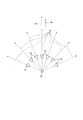
- FIG. 2 is an overhead view showing a configuration example of a microphone array in the voice input device of FIG. 1. It is an overhead view which shows the other structural example of the microphone array in the audio
- FIG. 2 is an overhead view showing an example of a positional relationship between a camera and a microphone array in the voice input device of FIG. 1. It is a figure of the perspective projection camera model for demonstrating an example of the camera reference
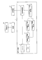
- FIGS. 1 is a block diagram showing a configuration example of a voice input device according to the present embodiment
- FIG. 2 is an overhead view showing a configuration example of a microphone array in the voice input device of FIG. 1, and FIG. It is an overhead view which shows the other structural example of the microphone array in 1 audio
- the audio input device 1 includes a microphone array 11, a camera 12, an in-image user coordinate detection unit 13, a camera reference user angle calculation unit 14, a camera reference user distance calculation unit 15, and a microphone array.
- a reference user angle calculation unit 16 and a directivity angle control unit 17 are provided.
- the microphone array 11 has a plurality of microphones that acquire sound.
- Each microphone may be an audio input element, but FIG. 2 shows an example in which the microphone array 11 is configured by arranging a plurality of super-directional microphones 21.
- Each super-directional microphone 21 is a microphone having a sharp directivity, such as a gun microphone, and is arranged so that the sound collection direction 23 of each super-directional microphone 21 is substantially radial around an arbitrary point in space.
- the In the present embodiment, the center point of the sound collection direction 23 is referred to as a microphone array reference point 22.
- the microphone array reference point 22 does not need to be exactly one point, and the sound collection directions may intersect with each other in substantially the same region.
- the reference direction of the directivity angle of the microphone array 11 is determined as a central direction in which the microphone array 11 is arranged (a direction connecting the array center and the microphone array reference point 22). Is called the microphone array front direction 24.
- a virtual straight line passing through the microphone array reference point 22 and extending in the microphone array front direction 24 is referred to as a microphone array axis 25. That is, the straight line connecting the center of the array and the microphone array reference point is the microphone array axis 25.
- the directivity angle is controlled by the configuration shown in FIG. 2, but the method of controlling the directivity angle is not limited to this.
- a plurality of microphones having low directivity may be used as the microphone array 11, and a microphone array that controls the directivity angle by calculating a difference in time and volume of sound reaching each microphone may be used.
- the arrangement of the microphones illustrated in FIG. 3 is an arrangement example in which the microphone array 11 is realized by controlling the directivity angle by calculating the time difference between the voices reaching each microphone 31 (difference in the voice arrival time). .
- the microphone 31 is a microphone having weak directivity or a microphone having no directivity. When the directivity direction 32 (directivity angle) is determined, there is a difference in the arrival time of sound to each microphone 31.
- a microphone array reference point 22 is defined as a reference point for determining the directivity direction 32, and the microphone array front direction 24 and the microphone array axis 25 are defined in the same manner as in the configuration of FIG. With the microphone array 11 having such a configuration, the directivity angle of the input audio information can be controlled by the directivity angle control unit 17.
- the camera 12 has an image sensor and is an image input unit that inputs an image or an image and shooting information about the image (for example, including a focal length in the image) by shooting.
- the imaging device include solid-state imaging devices such as a CCD (Charge-Coupled Device) sensor and a CMOS (Complementary Metal-Oxide Semiconductor) sensor.
- the camera 12 includes an optical component such as a lens in addition to the image sensor, and can be mounted on the voice input device 1 as a camera module.
- a camera with a wide shooting angle of view such as a camera equipped with a super-wide-angle lens or a fisheye lens, because a voice acquisition target user (hereinafter simply referred to as “user”) can be photographed over a wide range. .
- the camera 12 in this embodiment transmits the captured image (and shooting information) to the in-image user coordinate detection unit 13.
- the camera 12 does not have to be dedicated to still image shooting, and may be dedicated to moving image shooting or may be used for both moving image and still image.
- the image used by the in-image user coordinate detection unit 13 is basically a still image, and when a moving image is used, a frame immediately before the sound acquisition may be used.
- FIG. 4 is an overhead view showing an example of an arrangement relationship between the camera 12 and the microphone array 11 in the present embodiment.
- the camera 12 and the microphone array 11 are arranged such that their reference points 41 and 22 are separated by a predetermined distance L. Since the change in the user position is greater in the horizontal direction, which is the left-right direction, than in the vertical direction, which is the vertical direction, the camera 12 and the microphone array 11 are moved in the horizontal direction so that the predetermined distance L is in the horizontal direction. It is good to arrange them apart. This is because the desired sound with reduced noise can be output as the input sound by controlling the directivity direction as described later with respect to the separated direction.
- the camera reference point 41 is a point used as a reference when calculating an angle (direction) where the user exists with respect to the camera 12 within the shooting range 40 of the camera 12.
- an example in which the camera focus is the camera reference point 41 is given, but the present invention is not limited to this.
- the camera 12 and the microphone array 11 can be arranged apart from each other in the direction other than the horizontal direction, and the directivity direction can be controlled accordingly.
- the camera 12 and the microphone array 11 are arranged so that the camera reference point 41 and the microphone array reference point 22 are not at the same position in the horizontal direction. This is because the change in the user position is larger in the horizontal direction than in the vertical direction as described above.
- the positional relationship between the camera 12 and the microphone array 11 is built in the voice input device 1, the positional relationship is known at the design and manufacturing stage.
- the positional relationship between the camera 12 and the microphone array 11 can be changed independently, the positional relationship between the camera 12 and the microphone array 11 is measured in advance. Fix it so that it will not change later.
- the camera optical axis 42 and the microphone array axis 25 are substantially parallel, the camera shooting direction 43 and the microphone array front direction 24 are the same direction, and pass through the camera reference point 41 with respect to the camera optical axis 42.
- the microphone array 11 and the camera 12 are installed in such a positional relationship that the microphone array reference point 22 exists on a substantially vertical straight line 44. Further, the microphone array 11 is installed so that the straight line 44 exists on the same plane in which the sound collection direction 23 (FIG. 2) extends radially.
- the in-image user coordinate detection unit 13 detects user position information from an image (input image) taken by the camera 12.
- the user position can be detected by detecting a face area from the image information, for example.
- the two-dimensional coordinates of the user's face in the image and the size of the user's face in the image are calculated.
- a technique for detecting a face a generally used method can be used. For example, there is a method in which an image obtained by photographing a standard human face is stored in advance as reference data, and the face is detected from a correlation value with the reference data.
- human face images standard male and female facial images may be stored as reference data, and generational standard male and female facial images. May be held as reference data.
- a specific user's face can be held, such an example will be described later as a third embodiment.
- the in-image user coordinate detection unit 13 transmits the two-dimensional coordinates where the user's face in the image exists to the camera reference user angle calculation unit 14, and the size of the user's face in the image as the camera reference user distance calculation unit 15. To communicate.
- the detection of the face area is preferable as a process for detecting the user position because there is a mouth that speaks. Of course, the mouth area in the face may be detected instead.
- the in-image user coordinate detection unit 13 transmits the two-dimensional coordinates where the faces of the respective users in the image exist to the camera reference user angle calculation unit 14, and each in the image The size of the user's face is transmitted to the camera reference user distance calculation unit 15. At this time, since a large amount of data is detected when a large number of users are detected, a specific number of detection results may be transmitted according to the two-dimensional coordinate position of the detected face and the size of the detected face. Good.
- the camera reference user angle calculation unit 14 calculates a camera reference user angle based on the input image.
- the camera reference user angle is an angle of the user position of the voice acquisition target user with reference to the camera 12.
- the camera reference user angle calculation unit 14 in the present embodiment includes a user who uses the camera reference point 41 as a reference from the in-image user face coordinates that are two-dimensional coordinates in the image transmitted from the in-image user coordinate detection unit 13.
- the camera reference user angle which is an angle indicating the direction to perform, is calculated.
- the camera reference user angle is calculated by using a perspective projection camera model.
- FIG. 5 is a diagram of a perspective projection camera model for explaining an example of a camera reference user angle calculation method in the voice input device 1.
- This perspective projection camera model is a model of the camera 12 viewed from a direction perpendicular to the camera optical axis 42 and the straight line 44. If the focal length of the camera 12, the pixel pitch of the sensor (imaging device), and the coordinates of the intersection of the sensor pixel and the optical axis 42 are known, the position of the projection plane 51 can be calculated. The angle indicated by the direction 53 of the user face coordinates 52 in the image on the projection plane 51 from the camera reference point 41 is the camera reference user angle ⁇ . In this way, the camera reference user angle ⁇ can be calculated.
- the camera reference user angle calculation unit 14 transmits the calculated camera reference user angle ⁇ to the microphone array reference user angle calculation unit 16.
- the projection plane 51 becomes a projection camera model that is a sphere centered on the camera reference point 41, and the angle of view and image circle radius of the fish-eye camera, sensor If the coordinates of the intersection of the pixel and the optical axis 42 are known, the position of the projection plane 51 can be calculated, so that the camera reference user angle ⁇ can be calculated by the same method.
- the camera reference user distance calculation unit 15 calculates a camera reference user distance based on the input image.
- the camera reference user distance is a distance to the user position based on the camera 12.
- the camera reference user distance calculation unit 15 in this embodiment calculates the camera reference user distance from the camera reference point to the user from the size of the user's face in the image transmitted from the in-image user coordinate detection unit 13. .
- Each variable of Expression (1) is a camera standard user distance calculated by D
- d is a camera standard user distance at the time of capturing reference data
- t is the number of vertical pixels of the reference data
- t ′ is a user coordinate detection unit 13 in the image. This is the number of vertical pixels in the extraction range sent from.
- the user coordinate detection unit 13 in the image does not hold the reference data for each gender or generation (reference data with different face sizes). It is preferable to estimate the age and sex from the face to be detected and calculate the camera reference user distance D because the error in distance calculation can be reduced.
- This can be realized by setting the relationship between the face size and distance of the reference age and increasing or decreasing the distance according to the estimated age. It can also be realized by setting the relationship between the face size and distance for each age. For example, when faces of the same size are detected, the distance between the child and the adult is different, and the child is present closer than the adult. Therefore, for example, when the detected face is a child, the calculated distance may be increased by a predetermined ratio.
- the camera reference user distance calculation unit 15 transmits the calculated camera reference user distance D to the microphone array reference user angle calculation unit 16.
- the distance D from the camera reference point 41 to the user is calculated from the size of the user face in the image, but this method is used as the method for calculating the distance from the camera reference point 41 to the user.
- various types of shooting information acquired when the image is acquired by the camera 12 can also be used. For example, if the camera 12 has an autofocus function, the distance of the user position is calculated by using the focus distance when the face area is detected and the detected face area is focused as the user position distance. can do.
- parallax information of the user face area is obtained as shooting information, and the distance from the camera reference point 41 to the user from the parallax information May be calculated. Further, the various distance calculation methods described above can be applied in combination.
- the in-image user coordinate detection unit 13 in the present embodiment detects a face area of a subject (mainly a person but may be an animal) in the input image, and the camera reference user angle calculation unit 14 and the camera reference user distance.
- the calculation unit 15 calculates the camera reference user angle ⁇ and the camera reference user distance D using the position of the face area as the user position. However, only one of the camera reference user angle ⁇ and the camera reference user distance D may be calculated based on the detection of the face area. Alternatively, either the camera reference user angle ⁇ or the camera reference user distance D can be calculated by detecting the user position without using the face area detection. This point is the same in other embodiments.
- this configuration example is the same as the in-image user coordinate detection unit 13. This is synonymous with providing both the camera reference user angle calculation unit 14 and the camera reference user distance calculation unit 15 with a function for specifying the user position.
- the microphone array reference user angle calculation unit 16 is based on the predetermined distance L, the camera reference user angle ⁇ transmitted from the camera reference user angle calculation unit 14, and the camera reference user distance D transmitted from the camera reference user distance calculation unit 15. Then, the microphone array reference user angle is calculated.
- the microphone array reference user angle is an angle of the user position with respect to the microphone array 11, and in this example, a user angle with respect to the microphone array reference point 22.
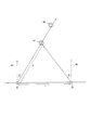
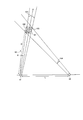
- FIG. 6 is a view for explaining the method of calculating the microphone array reference user angle, and is an overhead view showing an example in the case where the user is positioned between the camera 12 and the microphone array 11.
- the position of the user 61 relative to the microphone array reference point 22 can be calculated by geometric calculation. Specifically, since the positional relationship between the camera reference point 41 and the microphone array reference point 22 is set in advance including the predetermined distance L when designing the audio input device 1, the microphone array reference point 22 is used as a reference. The user's microphone array reference user angle ⁇ can be calculated.
- the directivity angle of the microphone array 11 is directed only to the user 61.
- the microphone array reference user angle ⁇ calculated by the microphone array reference user angle calculation unit 16 is transmitted to the directivity angle control unit 17.
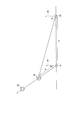
- FIG. 7 is an overhead view showing an example of the case where the user is located in the same direction as viewed from the camera 12 and the microphone array 11 and close to the microphone array 11.
- FIG. 8 is the same as viewed from the camera 12 and the microphone array 11. It is a bird's-eye view which shows an example in case a user is located in the direction and the place near the camera 12.
- the position of the user 61 relative to the microphone array reference point 22 can be calculated from the camera reference user angle ⁇ and the camera reference user distance D by geometric calculation.
- the microphone array reference user angle ⁇ of the user 61 with respect to the microphone array reference point 22 can be calculated using the positional relationship between the camera reference point 41 and the microphone array reference point 22.
- the camera 12 and the microphone array 11 are arranged so that the camera reference point 41 and the microphone array reference point 22 are at the same position, when the other speaker 62 is behind the user 61, the same as viewed from the camera.
- the user can not detect overlapping images taken by the camera 12. Therefore, the camera 12 and the microphone array 11 are arranged in a state in which the angle calculated by the camera reference user angle calculation unit 14 is changed by a predetermined distance L.
- the predetermined distance L may be any value.
- the directivity angle control unit 17 controls the directivity angle of the microphone array 11 based on the image input by the camera 12.
- the directivity angle control unit 17 controls the microphone array 11 to have the microphone array reference user angle ⁇ described above. Control the pointing angle. That is, the directivity angle control unit 17 controls the directivity angle of the microphone array 11 toward the microphone array reference user angle ⁇ transmitted from the microphone array reference user angle calculation unit 16 and outputs the sound transmitted from the microphone array 11.
- the angles ⁇ and ⁇ are expressed as angles formed by the axes 42 and 25 regardless of whether they are positive or negative. The direction may be determined arbitrarily.
- Control by selecting the sound corresponding to the microphone array reference user angle ⁇ from the sound information of the superdirectional microphone 21 (or the microphone 31 in FIG. 3) sent from the microphone array 11, Control can be realized.
- the microphone array 11 uses a microphone with low directivity, it is possible to acquire sound from a specific angle as sound information by taking into account the difference in sound arrival time.
- the angle ⁇ and the angle ⁇ are each described as one value.
- a predetermined allowable range can be set for each angle.
- the allowable range of the calculated angle can be set in advance as a certain range such as ⁇ 5 °. Note that the allowable range does not need to be set as an angle in advance or does not need to be a certain range, and such an example will be described later as a second embodiment.
- the camera 12 and the microphone array 11 are disposed in a state where the camera reference user angle ⁇ is changed and is separated by a predetermined distance L, and is separated from the camera 12 by a target distance (the above distance D).
- the directivity angle of the microphone array 11 By directing the directivity angle of the microphone array 11 to the selected position, when another user (another speaker) 62 is at substantially the same angle as the user 61 when viewed from the camera 12, the voice of each user is independently input. It is possible to reduce misrecognition of the user voice by inputting only the voice of the user who is the target of voice acquisition separately from the voice of another user. Note that by applying a moving image as an input image, the directivity angle is sequentially switched in a direction that matches the position of the user, so that it is possible to reduce erroneous recognition even if the user moves.
- a recording person such as a person who is speaking at a different distance in the same direction as the speaker (user) as a voice acquisition target.
- speech input device such as a person who is speaking at a different distance in the same direction as the speaker (user)
- the user's voice is determined by determining the distance and inputting only the voice of the user at the target distance. Misrecognition can be reduced, and user voice can be acquired with low noise.
- FIG. 9 is a diagram illustrating a configuration example of a microphone array in the voice input device according to the present embodiment.
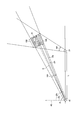
- 10 and 11 are diagrams for explaining an example of a method of calculating the microphone array reference user angle range in the voice input device according to the present embodiment.
- FIG. 10 shows an example when the calculation error range is large
- FIG. 11 shows an example when the calculation error range is small.
- the block diagram showing the configuration example of the voice input device in the present embodiment is the same as FIG. 1 shown in the first embodiment, and detailed description of each part is omitted.
- the operations of the microphone array 11 and the camera 12 are the same as those shown in the first embodiment.
- the directivity angle control unit 17 in the present embodiment is configured to be able to control the directivity range (the range indicated by the directivity angle) of the microphone array 11 of FIG. 1, and the microphone array 11 can also perform such control. It consists of multiple microphones. In the present embodiment, as illustrated in FIG. 9, it is desirable to use a plurality of microphones 31 having low or no directivity as the microphone array 11, and such an example is given. However, even a plurality of microphones having strong directivity can be used.
- the directivity angle control unit 17 emphasizes the sound in each directivity direction (directivity angle) within the directivity range (directivity area) 91 in which the sound is to be acquired by the same method as in the first embodiment, and the sound at other angles. Suppress.
- the directivity range is controlled by using the difference in the voice arrival times to the plurality of microphones 31.
- the directivity angle control unit 17 can control the directivity range of the microphone array 11.
- this control will be specifically described. Note that even a plurality of microphones having high directivity can be controlled by driving one or a plurality of microphones that are directed to the directivity range indicated by the directivity angle.
- the camera 12 transmits the captured image (and the captured information) to the in-image user coordinate detection unit 13 as in the first embodiment.
- the camera 12 transmits the captured image (and the captured information) to the in-image user coordinate detection unit 13 as in the first embodiment.
- the camera reference user angle calculation unit 14 operates in consideration of the angle calculation error range so that a desired effect can be appropriately obtained even if the angle calculation accuracy is different.
- the camera reference user angle calculation unit 14 can reduce malfunction due to an angle calculation error by setting an allowable range when calculating the camera reference user angle ⁇ from the user face coordinates in the image. Therefore, the camera reference user angle calculation unit 14 also calculates an angle calculation error range at the calculated angle ⁇ when calculating the camera reference user angle ⁇ from the user face coordinates in the image.
- the angle calculation error range is calculated, for example, by calculating camera reference user angles ⁇ a and ⁇ b (see FIG. 10) when the user face coordinates in the image are shifted by one pixel left and right in the camera 12, and the camera reference user angles ⁇ a, A range with ⁇ b as a boundary is an angle calculation error range 101.
- the angle calculation error range varies depending on the calculated camera reference user angle ⁇ .
- an error tolerance range is set as the error range is constant regardless of the calculated camera reference user angle ⁇ as described in the first embodiment.
- the angle calculation error range of the area where the resolution at the center of the input image is high is set as a reference, the resolution is low in the peripheral area (edge side) of the input image. There is a possibility of being excluded.
- the angle calculation error range of the low resolution area located around the input image is set as a reference, an excessive tolerance range is provided in the center area of the image, although the resolution is high and the angle calculation error is small. There is a possibility that noise is included in the desired voice.
- the angle calculation error range is different depending on the calculated camera reference user angle ⁇ , and an allowable range of error is set depending on the angle ⁇ , and the input image
- the angle calculation error range is reduced at the center of the input image, and the angle calculation error range is increased in the peripheral region of the input image.
- the angle calculation error range has been described as a range in which one pixel is shifted to the left and right, but the angle calculation error range can be set as appropriate depending on shooting conditions such as camera resolution.
- the angle calculation error range can be calculated from the calculated angle ⁇ every time, but an LUT (Look Up Table) that defines the angle calculation error range for each calculated angle ⁇ may be held.
- the camera reference user angle calculation unit 14 transmits the calculated camera reference user angle ⁇ and the angle calculation error range 101 to the microphone array reference user angle calculation unit 16.
- the camera reference user distance calculation unit 15 sets an allowable range when calculating the camera reference user distance D from the size of the face of the user in the image transmitted from the user coordinate detection unit 13 in the image, It is possible to reduce malfunctions due to distance calculation errors. Therefore, the camera reference user distance calculation unit 15 also calculates a distance calculation error range when calculating the camera reference user distance D from the in-image user face coordinates.
- the distance calculation error range includes distances Da and Db when the size of the user's face in the image is increased by one pixel on the left and right and by one pixel on the left and right (see FIG. 10). And a range with the calculated distances Da and Db as a boundary is set as a distance calculation error range 102.
- the distance calculation error varies depending on the calculated camera reference user distance D.
- an allowable range of error is set assuming that the distance calculation error range is constant regardless of the calculated camera reference user distance D.
- the distance calculation error range when the distance D is short is set as a reference, the distance calculation error increases when the distance D is long, and a desired user voice may be excluded.
- the distance calculation error range when the distance D is long is set as a reference, an excessive allowable range is provided even though the distance calculation error is small when the distance D is short. There is a possibility of becoming.
- the distance calculation error range 102 also changes depending on the camera reference user angle ⁇ at the time of calculation. For example, when a camera equipped with a fisheye lens is used as the camera 12, the resolution of the face area decreases as the camera reference user angle ⁇ increases. When the resolution of the captured image is high and the distance calculation error is small, the change in the user distance when the size of the user face in the image is shifted by one pixel is small. On the other hand, when the resolution of the captured image is low and the distance calculation error is large, the change in the user distance is large when the size of the user face in the image is shifted by one pixel. That is, the distance calculation error varies depending on the calculated camera reference user angle ⁇ .
- an allowable error range is set assuming that the distance calculation error range is constant regardless of the calculated camera reference user angle ⁇ .
- the distance calculation error range of the area where the resolution at the center of the input image is high (corresponding to the area where the angle ⁇ is small) is set as a reference
- the distance calculation error is small because the resolution is low in the peripheral area of the input image
- the distance calculation error range of the low resolution area (corresponding to the area where the angle ⁇ is large) located around the input image is set as a reference
- the area at the center of the image has high resolution and small distance calculation error. Since an excessive allowable range is provided, there is a possibility that noise is included in a desired user voice.
- the distance calculation error range is different depending on the camera reference user distance D and the camera reference user angle ⁇ , and the allowable range of error depends on the distance D and the angle ⁇ .
- the distances Da and Db are calculated when the size of the user's face in the image is increased by one pixel on the left and right and by one pixel on the left and right, and the distance between the calculated distances Da and Db is calculated as the boundary.
- the distance calculation error range 102 is small at the center of the input image (corresponding to a region where the angle ⁇ is small), and at the peripheral region of the input image (corresponding to a region on the edge side where the angle ⁇ is large).
- the distance calculation error range 102 When the distance calculation error range 102 is large and the distance D is short, the distance calculation error range 102 is small, and when the distance D is long, the distance calculation error range 102 is large. As a result, noise reduction and desired voice acquisition can be appropriately performed as a result, which is preferable.
- the distance calculation error range has been described as a range in which the size of the user's face in the image is shifted by one pixel to the left and right, but can be set as appropriate depending on shooting conditions such as camera resolution.
- the distance calculation error range can be calculated every time from the calculated angle ⁇ and the calculated distance D, but an LUT that defines the distance calculation error range for each calculated angle ⁇ and the calculated distance D is held. May be.
- the distance calculation error range is different depending on the distance D and the angle ⁇ , and an example in which the allowable range of the error is set depending on the distance D and the angle ⁇ is given.
- the distance calculation error range may be different depending on only one of the distance D and the angle ⁇ , and the allowable range of error may be set depending on the distance D or the angle ⁇ .
- a LUT that defines a distance calculation error range for each calculated distance D or a LUT that defines a distance calculation error range for each angle ⁇ at the time of calculation is held, and a distance calculation error is referred to by referring to the LUT. You may ask for.
- the camera reference user distance calculation unit 15 of the present embodiment transmits the camera reference user distance D, which is the calculated distance from the camera reference point 41 to the user, and the distance calculation error range 102 to the microphone array reference user angle calculation unit 16. .
- the microphone array reference user angle calculation unit 16 uses the microphone array reference point 22 as a reference based on the predetermined distance L, the camera reference user angle ⁇ , the angle calculation error range 101, the camera reference user distance D, and the distance calculation error range 102.
- the microphone array reference user angle range that is the range of the user angle is calculated.
- the microphone array reference user angle calculation unit 16 receives the predetermined distance L, the camera reference user angle ⁇ and the angle calculation error range 101 transmitted from the camera reference user angle calculation unit 14, and the camera reference user distance calculation unit 15. From the camera reference user distance D and the distance calculation error range 102, a range 103 that can be estimated that the user 61 exists is calculated by geometric calculation.
- the range 103 is a common range that is a common part between the angle calculation error range 101 and the distance calculation error range 102.
- a microphone array reference user angle range 104 with reference to the microphone array reference point 22, which includes 103, can be calculated. At this time, a large range 103 is detected with respect to the size of the face of the user 61 as shown in FIG. 10, or a small range 103 is detected with respect to the size of the face of the user 61 as shown in FIG. Sometimes.
- the range 103 is calculated in consideration of an appropriate error based on the distance D and the angle ⁇ , the range 103 can be said to be an appropriate range in consideration of the error, and the microphone array reference user angle range obtained from the range 103 104 is also an appropriate range.
- the microphone array reference user angle range 104 calculated by the microphone array reference user angle calculation unit 16 is transmitted to the directivity angle control unit 17. At this time, the microphone array reference user angle (the median angle of the range 104) may be transmitted at the same time.
- the directivity angle control unit 17 in this embodiment controls the directivity range 91 of the microphone array 11 so that the sound of the microphone array reference user angle range 104 transmitted from the microphone array reference user angle calculation unit 16 can be acquired. That is, the directivity angle control unit 17 in the present embodiment controls the directivity range 91 that is the directivity angle of the microphone array 11 to be the microphone array reference user angle range 104. Thereby, the directivity range of the microphone array 11 can be appropriately controlled according to the microphone array reference user angle range 104.
- an appropriate microphone array reference user angle range 104 can be calculated according to the resolution for each camera reference user angle ⁇ of the camera 12 and the resolution for each camera reference user distance D.
- the directivity range of the microphone array can be set appropriately. Further, the microphone array reference user angle (the angle of the median value in the range 104) is also transmitted, or the microphone array reference user angle (the angle ⁇ described above) is obtained from the microphone array reference user angle range 104 as the angle of the median value. It is also possible to perform control such as increasing the voice input level in the directivity direction indicated by and lowering the voice input level as it approaches the end of the range 104.
- the microphone array reference user angle range 104 is set with respect to the result of calculating the angle calculation error range 101 and the distance calculation error range 102. However, only the angle calculation error range 101 or the distance calculation error range 102 is given. It is possible to perform such setting only by using only, and in any case, an effect of realizing noise reduction and desired voice acquisition can be obtained.
- a setting is performed only in the angle calculation error range 101
- such a setting is performed only in the distance calculation error range 102 so as to sandwich the arc that is the distance D and the angle calculation error range 101.
- the microphone array reference user angle range 104 is set so as to sandwich the line segment that is the angle ⁇ and the distance calculation error range 102.
- the microphone array reference user angle calculation unit 16 may calculate the microphone array reference user angle range based on the predetermined distance, the camera reference user distance, the camera reference user angle, and the angle calculation error range. Alternatively, the microphone array reference user angle calculation unit 16 may calculate the microphone array reference user angle range based on a predetermined distance, a camera reference user angle, a camera reference user distance, and a distance calculation error range.
- examples of calculating the angle calculation error range and the distance calculation error range are such that the edge side of the input image is often out of focus compared to the center part, and therefore the camera reference user angle and camera reference user Since it can be said that the distance calculation error often increases, it is useful even when the user position is detected by a method other than the detection of the face area.
- the microphone array reference user angle range is set according to the camera reference user angle and / or the camera reference user distance, more specifically, the resolution and / or the camera reference user angle. Calculation is performed according to the resolution for each camera reference user distance, and thus the directivity range of the microphone array can be appropriately controlled.
- Embodiment 3 of the present invention will be specifically described.
- a block diagram illustrating a configuration example of the voice input device according to the present embodiment is the same as that illustrated in FIG. 1 according to the first embodiment, and a detailed description of each unit is omitted.
- the operations of the microphone array 11 and the camera 12 are the same as those shown in the first embodiment.
- the features of the present embodiment can also be applied to the second embodiment.
- the in-image user coordinate detection unit 13 identifies an individual user from the image captured by the camera 12 and detects the position information of the user.
- the user can be specified by performing template matching on an image obtained by photographing a user's face (hereinafter referred to as a user's face) stored in advance, using an image whose magnification is changed in several stages as a template image.
- the range of the same number of pixels as the template image is extracted as a window image from the image for detecting the user face, and the sum of the pixel value differences from the corresponding template image pixels for all the pixels in the window image Calculate the value. Differences are calculated for all window images that can be extracted from the user face detection image, and a range in which a window image with the smallest difference is extracted is searched.
- the two-dimensional coordinates for the image that detects the user face in the extraction range in which the difference is the smallest and the difference is less than or equal to the threshold value are set as the two-dimensional coordinates of the user's face. For example, the number of vertical pixels is set as the size of the user face.
- the in-image user coordinate detecting unit 13 transmits the in-image user face coordinates and the user specifying information in the image to the camera reference user angle calculating unit 14, and the size and user specifying information for each user face in the image. (ID indicating the user or name) is transmitted to the camera reference user distance calculation unit 15.
- the camera reference user angle calculation unit 14 calculates a camera reference user angle from the user face coordinates in the image of the specified user, and associates the camera reference user angle with the user specifying information as to which user the camera reference user angle belongs to.
- the calculation of the camera reference user angle can be realized by the same method as in the first embodiment.
- the camera reference user angle calculation unit 14 transmits the camera reference user angle to which the user specifying information is given to the microphone array reference user angle calculation unit 16.
- the camera reference user distance calculation unit 15 calculates the camera reference user distance from the camera reference point to each user from the size of the user's face in the image transmitted from the in-image user coordinate detection unit 13, Which user the camera reference user distance belongs to is associated with user identification information.
- the camera reference user distance is implemented by photographing an image of a user face used as a template image by the in-image user coordinate detection unit 13 using the camera 12 and measuring the distance at the time of photographing. It can be calculated by the calculation of equation (1) as in the first mode.
- each variable of the expression (1) is a camera reference user distance calculated by D
- d is a camera reference user distance at the time of photographing a template image
- t is the number of vertical pixels of the template image
- t ′ is an in-image user.
- the size of the user's face specified by the in-image user coordinate detection unit 13 is calculated by calculating the camera reference user distance using the distance at the time of shooting the template image of the user.
- the camera reference user distance reflecting the distance is calculated, and an error in distance calculation can be reduced.
- the camera reference user distance calculation unit 15 transmits the camera reference user distance given the user identification information to the microphone array reference user angle calculation unit 16.
- the microphone array reference user angle calculation unit 16 is based on the predetermined distance L, the camera reference user angle ⁇ transmitted from the camera reference user angle calculation unit 14, and the camera reference user distance D transmitted from the camera reference user distance calculation unit 15. Thus, the microphone array reference user angle that is the user angle with respect to the microphone array reference point 22 is calculated.
- the microphone array reference user angle can be calculated from the camera reference user angle ⁇ and the camera reference user distance D to which the same user identification information is given in addition to the predetermined distance L by the same method as in the first embodiment.
- the microphone array reference user angle calculation unit 16 uses the user identification information transmitted from the camera reference user angle calculation unit 14 and the user identification information transmitted from the camera reference user distance calculation unit 15 as the microphone array reference user angle ⁇ . Give. The microphone array reference user angle calculation unit 16 transmits the microphone array reference user angle ⁇ to which the user specifying information and the user specifying information are given to the directivity angle control unit 17.
- the directivity angle control unit 17 controls the directivity angle of the microphone array 11 toward the microphone array reference user angle ⁇ transmitted from the microphone array reference user angle calculation unit 16, and outputs the sound transmitted from the microphone array 11. Thereby, the distance calculation in consideration of the actual face size of the user can be performed, and the directivity angle control in the directivity angle control unit 17 can be performed with high accuracy.
- the face photographing data and the distance are associated with each other as reference data.
- the face attribute detected by the in-image user coordinate detection unit 13 is used as user identification information.
- the camera reference user distance may be corrected.
- the face attribute can be set by sex, age, etc., such that males are larger than females and adults are larger than children.
- a conventional method can be used to determine each attribute, and it can be estimated from the similarity of reference data.
- the directivity angle control in the directivity angle control unit 17 can be accurately performed by calculating the user distance in consideration of the face attribute.
- FIG. 12 is a block diagram illustrating a configuration example of a speech recognition apparatus according to Embodiment 4 of the present invention.
- the speech recognition apparatus according to the present embodiment is a speech recognition apparatus including the speech input device 1 and the speech recognition unit 121 described in Embodiment 3.
- this embodiment can be applied to both the first and second embodiments.
- the voice recognition unit 121 analyzes the voice input result transmitted from the voice input device 1 and outputs the analysis result.
- the analysis method a conventional method can be used.
- the speech is analyzed and recognized by comparing with reference data.
- the output result is converted into text data or used for controlling ON / OFF of the electric device. Since the speech recognition apparatus according to the present embodiment includes the speech input device 1 that can appropriately acquire desired speech with low noise, it is possible to recognize speech with high accuracy.
- the directivity angle control unit 17 can add the user identification information given to the microphone array reference user angle ⁇ used for directivity angle control to the voice transmitted from the microphone array 11 and output the voice. it can.
- speech recognition it is possible to use a speech recognition method with high speech recognition accuracy in accordance with the user, which is preferable because erroneous recognition of speech recognition can be reduced.
- the voice recognition reference data is updated from the user identification information and the voice input result, and voice recognition is performed using the reference data for each user.
- the feature amount a general speech parameter can be targeted, and there are intonation, frequency, and the like. Therefore, by providing the user identification information to the voice input, the reference data for voice recognition can be changed according to the user, and erroneous recognition can be reduced.
- FIG. 13 is a block diagram illustrating a configuration example of an image display apparatus according to the fifth embodiment of the present invention.
- the image display device according to the present embodiment is an image display device including the voice recognition device, the control unit 131, and the image display unit 132 described in the fourth embodiment.
- the voice recognition unit 121 may be configured as a separate device, and the image display device according to the present embodiment is implemented.
- the voice input device 1 as described in the first to third embodiments may be provided.
- the control unit 131 controls display contents of the image display unit 132, power ON / OFF, volume, and the like based on the voice recognition result for each user transmitted from the voice recognition unit 121.
- the image display apparatus according to the present embodiment can be operated by voice.
- the voice input device 1 is preferably mounted on a remote controller of the image display device.
- Examples of operation content include changing the TV broadcast channel, calling up the program guide, and specifying the program.
- the image display apparatus includes the voice input device 1 that can appropriately obtain desired voice with low noise, and can recognize voice with high accuracy. Therefore, more accurate operation using voice can be performed. It can be carried out.
- the timing of shooting by the camera 12 may be performed when such an operation is performed.
- the timing of shooting by the camera 12 in the voice input device 1 may be during voice input or immediately before or after voice input, and a predetermined operation (for example, It may be when the voice input button is pressed or a shutter button different from the voice input operation is pressed.
- the voice input device 1 includes an image display unit
- the user specifies the user position by touching the user's face while the captured image is displayed by the camera 12.
- the camera reference user angle and the camera reference user distance can also be calculated based on the designated position.
- an image display device including a voice input device that can appropriately control the directivity range of the microphone array 11 can be provided. Furthermore, since the image display apparatus according to the present embodiment has user position detection functions such as the camera 12 and the in-image user coordinate detection unit 13, it is possible to detect in-image user coordinates of a plurality of users. In addition, the image of the camera 12 can be displayed on the image display unit 132. In addition, in this embodiment, the voice input device 1 can separately input a plurality of user voices with low noise. Therefore, if the image display apparatus according to the present embodiment is used, for example, a video conference system that can cut out and display images of a plurality of users, and distribute the images and sounds of each user separately for each user. Can be built. In addition, examples of the image display device in the present embodiment include a mobile phone (including a so-called smartphone) and a tablet.
- each component of the apparatus according to the present invention is, for example, a microprocessor (or DSP: Digital Signal Processor). It can be realized by hardware such as peripheral devices such as a memory, a bus, an interface, and a remote controller, and software executable on these hardware. A part of the hardware can be mounted as an integrated circuit / IC (Integrated Circuit) chip set. In this case, the software may be stored in the memory. In addition, all the components of the present invention may be configured by hardware, and in that case, a part of the hardware can also be mounted as an integrated circuit / IC chip set.
- a microprocessor or DSP: Digital Signal Processor
- a recording medium on which a program code of software for realizing the functions in the various configuration examples described above is recorded is a voice input device or a device (may be a general-purpose computer) including the same, and a microphone array 11 and the camera 12 are supplied to a built-in or connected device, and the program code is executed by a microprocessor or a DSP in the device, and the object of the present invention is achieved.
- the software program code itself realizes the functions of the above-described various configuration examples. Even if the program code itself or a recording medium (external recording medium or internal storage device) on which the program code is recorded is used.
- the present invention can be configured by the control side reading and executing the code.
- Examples of the external recording medium include various media such as an optical disk such as a CD-ROM or a DVD-ROM and a nonvolatile semiconductor memory such as a memory card.
- Examples of the internal storage device include various devices such as a hard disk and a semiconductor memory.
- the program code can be downloaded from the Internet and executed, or received from a broadcast wave and executed.
- the voice input device As described above, the voice input device according to the present invention and the voice recognition device and the image display device including the voice input device have been described. As described above, the present invention has the arrangement as described above. A voice input direction changing method in a voice input device including a microphone array and a camera can also be adopted.
- a camera reference user angle calculation unit calculates a camera reference user angle that is an angle of a user position of an audio acquisition target user with reference to the camera, based on an image input by the camera;
- a camera reference user distance calculating unit calculating a camera reference user distance, which is a distance to the user position based on the camera, based on the image;
- a microphone array reference user angle calculating unit Calculating a microphone array reference user angle, which is an angle of a user position with respect to the microphone array, based on the camera reference user angle and the camera reference user distance; And controlling the directivity angle of the microphone array so as to be at an angle.
- Other application examples are the same as those described for the voice input device, and a description thereof will be omitted.
- the program code itself is a program for causing a computer to execute the voice input direction changing method. That is, the program calculates a camera reference user angle, which is an angle of a user position of a voice acquisition target user based on the camera, based on an image input to the computer by the camera, and based on the image, Calculating a camera reference user distance, which is a distance from the camera to the user position, and a user based on the microphone array based on the predetermined distance, the camera reference user angle, and the camera reference user distance
- a step of calculating a microphone array reference user angle, which is a position angle, and a step of controlling the directivity angle of the microphone array so as to be the microphone array reference user angle are executed.
- Other application examples are the same as those described for the voice input device, and a description thereof will be omitted.
- the audio input device is based on a microphone array having a plurality of microphones for acquiring audio, a camera having an image sensor and inputting an image by photographing, and the image input by the camera.
- a directivity angle control unit that controls the directivity angle of the microphone array, wherein the camera and the microphone array are spaced apart from each other by a predetermined distance, and the speech input device
- a camera reference user angle calculation unit that calculates a camera reference user angle that is an angle of a user position of a voice acquisition target user based on the camera, and the user based on the camera based on the image
- a camera reference user distance calculation unit that calculates a camera reference user distance that is a distance to the position; the predetermined distance; the camera reference user angle;
- a microphone array reference user angle calculation unit that calculates a microphone array reference user angle that is an angle of a user position with respect to the microphone array based on the camera reference user distance
- the directivity angle control unit includes: The directivity angle of the microphone array is controlled so
- a recording person a user who uses the voice input device, such as a person who is speaking at a different distance in the same direction as the speaker (user) to be voice acquisition target, Basically, when there is an unintended sound source of a person who is different from the above-mentioned speaker), it is possible to reduce the misrecognition of the user voice by determining the distance and inputting only the voice of the user at the target distance, User voice can be acquired with low noise.
- the microphone array reference user angle calculation unit is configured to generate the microphone based on the predetermined distance, the camera reference user distance, the camera reference user angle, and an angle calculation error range corresponding to the camera reference user angle.
- An array reference user angle range may be calculated, and the directivity angle control unit may control the directivity angle of the microphone array so as to be within the microphone array reference user angle range. Since the microphone array reference user angle range is calculated according to the camera reference user angle, the directivity range of the microphone array can be appropriately controlled.
- the microphone array reference user angle calculation unit may calculate a distance calculation error according to the predetermined distance, the camera reference user angle, the camera reference user distance, the camera reference user angle, and / or the camera reference user distance.
- the microphone array reference user angle range may be calculated based on the range, and the directivity angle control unit may control the directivity angle of the microphone array so as to be within the microphone array reference user angle range. Since the microphone array reference user angle range is calculated according to the camera reference user distance, the directivity range of the microphone array can be appropriately controlled.
- the face area of the subject in the image may be detected, and the camera reference user angle and / or the camera reference user distance may be calculated using the position of the face area as the user position.
- the detection of the face area is preferable as a process for detecting the user position because there is a mouth that speaks.
- the image display device is characterized by including the above-described voice input device.
- voice input apparatus which can control the directivity range of a microphone array appropriately can be provided.
- D Camera reference user distance
- L Distance between camera and microphone array (predetermined distance)
- ⁇ Camera reference user angle
- ⁇ Direction direction
- 1 ... Audio input device, 11 ... Microphone array, 12 ... Camera, 13 ... In-image user coordinate detection unit, 14 ... camera reference user angle calculation unit, 15 ... camera reference user distance calculation unit, 16 ... microphone array reference user angle calculation unit, 17 ... directivity angle control unit, 21 ... superdirective microphone, 22
- Reference numeral 23 Microphone array reference point, 23: Sound collection direction
- 24 Microphone array front direction, 25 ... Microphone array axis, 31 ... Microphone, 32 ... Camera reference point, 40 ... Shooting range, 41 ... Camera reference point, 42 ... Camera light Axis, 43 ...
Landscapes
- Health & Medical Sciences (AREA)
- General Health & Medical Sciences (AREA)
- Otolaryngology (AREA)
- Physics & Mathematics (AREA)
- Engineering & Computer Science (AREA)
- Acoustics & Sound (AREA)
- Signal Processing (AREA)
- Studio Devices (AREA)
- Obtaining Desirable Characteristics In Audible-Bandwidth Transducers (AREA)
- Circuit For Audible Band Transducer (AREA)
Abstract
音声取得対象となるユーザと同じ方向で違う距離に発話中の人物など、録音者の意図しない音源がある場合に、ユーザ音声の誤認識を低減することが可能な音声入力装置を提供する。音声入力装置は、カメラの基準点(41)とマイクアレイの基準点(22)が所定距離Lだけ離間するようにカメラとマイクアレイを配置し、カメラで入力した画像に基づいてカメラを基準としたカメラ基準ユーザ角度θおよびカメラ基準ユーザ距離Dを算出する。そして、音声入力装置は、カメラ基準ユーザ角度θおよびカメラ基準ユーザ距離Dに基づいて、マイクアレイを基準としたマイクアレイ基準ユーザ角度αを算出し、マイクアレイ基準ユーザ角度αになるようマイクアレイの指向角度を制御する。
Description
本発明は、複数のマイクロフォンを有するマイクアレイを備え、特定の方向からの音声を入力することが可能な音声入力装置、およびその音声入力装置を備えた画像表示装置に関する。
複数のマイクロフォンを有するマイクアレイを利用して音声入力の指向角度を変化させ、特定の方向からの音声情報を強調して、それ以外の方向からの音声情報を抑制する方法が知られている。これを音声入力装置に搭載し、マイクアレイの指向角度を音声が発生している方向へ向けることで、音声認識の認識精度を向上することができる。このような方法により音声入力を行うときは、ユーザによって発話された音声の方向を特定して、発話された音声の方向へマイクアレイの指向角度を向ける。
しかし、音声情報のみから方向を特定するため、ユーザ以外の人物の音声情報など、ユーザが意図していない音声情報の発生方向に対しても指向角度が向けられてしまい、ユーザが意図しない音声情報が入力され認識されてしまうことがある。
そこで、カメラで撮影した画像情報からユーザの方向を検出して、その方向にのみ音声入力の指向角度を向けることで、意図しない音声が入力されることを低減する技術が提案されている(特許文献1を参照)。特許文献1に記載の技術では、カメラにより撮影された撮像画像を用いて動的に変化する話者方向を特定し、マイクロフォンの指向性方向を話者方向になるよう制御することで、音声認識の精度を向上させている。
しかしながら、特許文献1に記載の技術では次のような課題を有する。
カメラに対して音声取得対象のユーザの後ろに別の発話者が存在するときなど、カメラで検出したユーザの方向と同じ方向に録音者の意図しない音源が存在する場合、マイクアレイの指向角度をユーザの方向に向けてもユーザの意図しない音声が入力されてしまい、音声認識処理において誤認識が発生してしまうことがある。つまり、この技術では、例えば対象となるユーザと違う距離にいる人物の音声など、ユーザと同じ方向からのユーザの音声でない音も拾って認識してしまい、ユーザ音声の誤認識を起こしてしまう。
カメラに対して音声取得対象のユーザの後ろに別の発話者が存在するときなど、カメラで検出したユーザの方向と同じ方向に録音者の意図しない音源が存在する場合、マイクアレイの指向角度をユーザの方向に向けてもユーザの意図しない音声が入力されてしまい、音声認識処理において誤認識が発生してしまうことがある。つまり、この技術では、例えば対象となるユーザと違う距離にいる人物の音声など、ユーザと同じ方向からのユーザの音声でない音も拾って認識してしまい、ユーザ音声の誤認識を起こしてしまう。
本発明は、上述のような実状に鑑みてなされたものであり、その目的は、音声取得対象となるユーザと同じ方向で違う距離に発話中の人物など、録音者の意図しない音源がある場合に、ユーザ音声の誤認識を低減することが可能な音声入力装置、およびその音声入力装置を備えた画像表示装置を提供することにある。
上記の課題を解決するために、本発明の第1の技術手段は、音声を取得するマイクロフォンを複数有するマイクアレイと、撮像素子を有し撮影により画像を入力するカメラと、該カメラで入力された該画像に基づいて前記マイクアレイの指向角度を制御する指向角度制御部と、を備えた音声入力装置であって、前記カメラと前記マイクアレイが所定距離だけ離間して配置され、前記音声入力装置は、前記画像に基づいて、前記カメラを基準とした音声取得対象ユーザのユーザ位置の角度であるカメラ基準ユーザ角度を算出するカメラ基準ユーザ角度算出部と、前記画像に基づいて、前記カメラを基準とした前記ユーザ位置までの距離であるカメラ基準ユーザ距離を算出するカメラ基準ユーザ距離算出部と、前記所定距離、前記カメラ基準ユーザ角度、および前記カメラ基準ユーザ距離に基づいて、前記マイクアレイを基準としたユーザ位置の角度であるマイクアレイ基準ユーザ角度を算出するマイクアレイ基準ユーザ角度算出部と、をさらに備え、前記指向角度制御部は、前記マイクアレイ基準ユーザ角度になるよう前記マイクアレイの指向角度を制御することを特徴としたものである。
本発明の第2の技術手段は、第1の技術手段において、前記マイクアレイ基準ユーザ角度算出部は、前記所定距離と、前記カメラ基準ユーザ距離と、前記カメラ基準ユーザ角度と、前記カメラ基準ユーザ角度に応じた角度算出誤差範囲とに基づいて、前記マイクアレイ基準ユーザ角度範囲を算出し、前記指向角度制御部は、前記マイクアレイ基準ユーザ角度範囲になるよう前記マイクアレイの指向角度を制御することを特徴としたものである。
本発明の第3の技術手段は、第1の技術手段において、前記マイクアレイ基準ユーザ角度算出部は、前記所定距離と、前記カメラ基準ユーザ角度と、前記カメラ基準ユーザ距離と、前記カメラ基準ユーザ角度および/または前記カメラ基準ユーザ距離に応じた距離算出誤差範囲とに基づいて、前記マイクアレイ基準ユーザ角度範囲を算出し、前記指向角度制御部は、前記マイクアレイ基準ユーザ角度範囲になるよう前記マイクアレイの指向角度を制御することを特徴としたものである。
本発明の第4の技術手段は、第1~第3のいずれか1の技術手段において、前記画像における被写体の顔領域を検出し、該顔領域の位置を前記ユーザ位置として、前記カメラ基準ユーザ角度および/または前記カメラ基準ユーザ距離を算出することを特徴としたものである。
本発明の第5の技術手段は、画像表示装置において、第1~第4のいずれか1の技術手段における音声入力装置を備えたことを特徴としたものである。
本発明によれば、指向角度を制御できる音声入力装置において、音声取得対象となるユーザと同じ方向で違う距離に発話中の人物など、録音者の意図しない音源がある場合に、その距離を判定して目的の距離にいるユーザの音声のみを入力することでユーザ音声の誤認識を低減し、低ノイズでユーザ音声を取得することができる。
(実施形態1)
以下、図1~図8を参照し、本発明の実施形態1について具体的に説明する。
図1は、本実施形態に係る音声入力装置の一構成例を示すブロック図で、図2は、図1の音声入力装置におけるマイクアレイの一構成例を示す俯瞰図で、図3は、図1の音声入力装置におけるマイクアレイの他の構成例を示す俯瞰図である。
以下、図1~図8を参照し、本発明の実施形態1について具体的に説明する。
図1は、本実施形態に係る音声入力装置の一構成例を示すブロック図で、図2は、図1の音声入力装置におけるマイクアレイの一構成例を示す俯瞰図で、図3は、図1の音声入力装置におけるマイクアレイの他の構成例を示す俯瞰図である。
図1に示すように、本実施形態における音声入力装置1は、マイクアレイ11、カメラ12、画像内ユーザ座標検出部13、カメラ基準ユーザ角度算出部14、カメラ基準ユーザ距離算出部15、マイクアレイ基準ユーザ角度算出部16、および指向角度制御部17を備える。
マイクアレイ11は、音声を取得するマイクロフォンを複数有する。各マイクロフォンは音声入力素子であればよいが、図2では、マイクアレイ11は複数の超指向性マイクロフォン21を配置して構成した例を挙げている。各超指向性マイクロフォン21は、ガンマイクなどの鋭い指向性をもつマイクロフォンであり、空間上の任意の点を中心に、各超指向性マイクロフォン21の集音方向23が略放射状になるように配置される。本実施形態では、集音方向23の中心となる点をマイクアレイ基準点22と呼ぶ。ただし、マイクアレイ基準点22は正確に1点である必要はなく、各集音方向が略同一領域で交差するようにすればよい。
また、本実施形態では、マイクアレイ11の指向角度の基準とする方向をマイクアレイ11が配列する中央の方向(配列の中心とマイクアレイ基準点22とを結ぶ方向)に決め、以下、その方向をマイクアレイ正面方向24と呼ぶ。また、マイクアレイ基準点22を通りマイクアレイ正面方向24に伸びる仮想的な直線をマイクアレイ軸25と呼ぶ。つまり、配列の中心とマイクアレイ基準点とを結ぶ直線がマイクアレイ軸25となる。マイクアレイ11をこのように構成にしておくことで、入力される音声情報の指向角度を指向角度制御部17により制御することができる。
なお、本実施形態では図2に示す構成により指向角度の制御を実現しているが、指向角度を制御する方法はこれに限定されない。例えば、マイクアレイ11として指向性の弱いマイクロフォンを複数利用し、各マイクロフォンに到達する音声の時間や音量の差を計算することで指向角度の制御を行うマイクアレイを利用してもよい。図3で例示するマイクロフォンの配置は、各マイクロフォン31に到達する音声の時間差(音声到達時間の差)を計算することで指向角度の制御を行い、マイクアレイ11を実現する場合の配置例である。マイクロフォン31は、指向性が弱いマイクロフォンか、指向性が無いマイクロフォンである。指向方向32(指向角度)を決定すると、各マイクロフォン31への音声の到達時間に差ができる。各マイクロフォン31の音声をこの到達時間の差だけずらして重ね合わせることで、指向方向32からの音声成分のみを強調することができる。指向方向32を決定する際の基準とする点をマイクアレイ基準点22とし、図2の構成と同様にマイクアレイ正面方向24とマイクアレイ軸25を定義する。マイクアレイ11をこのような構成にしておくことで、入力される音声情報の指向角度を指向角度制御部17により制御することができる。
カメラ12は、撮像素子を有し、撮影により画像、または画像およびその画像についての撮影情報(例えばその画像における焦点距離などを含む)を入力する画像入力部である。上記の撮像素子の例としては、CCD(Charge Coupled Device)センサやCMOS(Complementary Metal Oxide Semiconductor)センサなどの固体撮像素子が挙げられる。カメラ12は、撮像素子のほかに、レンズなどの光学部品などを備え、カメラモジュールとして音声入力装置1に搭載することができる。カメラ12としては、超広角レンズや魚眼レンズを装着したカメラなど、撮影画角が広いカメラを利用すると、広い範囲で音声取得対象ユーザ(以下、単に「ユーザ」と呼ぶ)を撮影できるため好適である。
そして、本実施形態におけるカメラ12は、撮影した画像(および撮影情報)を画像内ユーザ座標検出部13に伝達する。なお、カメラ12は、静止画撮影専用である必要はなく、動画撮影専用であっても、動画・静止画兼用であってもよい。また、画像内ユーザ座標検出部13で使用する画像は、基本的に静止画であり、動画像を利用する場合には音声取得時直前のフレームを利用するなどすればよい。
図4は、本実施形態におけるカメラ12とマイクアレイ11の配置関係の一例を示す俯瞰図である。図4に示すように、カメラ12とマイクアレイ11はそれらの基準点41,22間が所定距離Lだけ離間して配置されている。ユーザ位置の変化は上下方向である鉛直方向への変化よりも左右方向である水平方向への変化が大きいため、所定距離Lが水平方向に向くようにカメラ12とマイクアレイ11とを水平方向に離間させて配置させるとよい。これは、離間した方向に対して、後述するように指向方向を制御することにより、ノイズを低減した所望の音声を入力音声として出力することが可能となるためである。カメラ基準点41は、カメラ12の撮影範囲40内においてカメラ12に対してユーザが存在する角度(方向)を算出する際に基準とする点である。本実施形態ではカメラ焦点をカメラ基準点41とした例を挙げるが、これに限ったものではない。無論、カメラ12とマイクアレイ11とは水平方向以外の方向に離間させて配置させ、それに応じて指向方向の制御を行うこともできる。
カメラ12とマイクアレイ11は、カメラ基準点41とマイクアレイ基準点22が水平方向に同一位置にならないように配置する。これは、上述したようにユーザ位置の変化が鉛直方向より水平方向への方が大きいためである。
また、カメラ12とマイクアレイ11との位置関係は、両者が音声入力装置1に内蔵されている場合、その位置関係は設計や製造の段階で既知である。一方、カメラ12とマイクアレイ11とが独立して可動できるような構造の場合、それらの位置関係が変化してしまうため、カメラ12とマイクアレイ11との位置関係をあらかじめ計測しておき、計測後に変化しないように固定する。本実施形態では、カメラ光軸42とマイクアレイ軸25が略平行になり、カメラ撮影方向43とマイクアレイ正面方向24が同じ方向になり、かつ、カメラ基準点41を通りカメラ光軸42に対して略垂直な直線44上にマイクアレイ基準点22が存在するような位置関係でマイクアレイ11とカメラ12を設置する。また、マイクアレイ11の向きは集音方向23(図2)が放射状に広がっている同一平面上に直線44が存在するように設置する。
画像内ユーザ座標検出部13は、カメラ12で撮影された画像(入力画像)内から、ユーザの位置情報の検出を行う。ユーザ位置は、例えば、画像情報から顔領域を検出することで検出することが可能である。画像内のユーザの顔の二次元座標、および、画像内のユーザの顔の大きさを算出する。顔を検出する技術は一般に利用されている方法を使用することができる。例えば、標準的な人物の顔が撮影された画像を、参照データとしてあらかじめ保有しておき、その参照データとの相関値から顔を検出する方法がある。ここで、人物の顔の画像としては、標準的な男性、女性の双方の顔の画像を参照データとして保有しておいてもよいし、さらに世代別の標準的な男性、女性の顔の画像を参照データとして保有しておいてもよい。なお、特定のユーザの顔を保有しておくこともできるが、そのような例については実施形態3として後述する。
画像内ユーザ座標検出部13は、画像内のユーザの顔が存在する二次元座標をカメラ基準ユーザ角度算出部14に伝達し、画像内のユーザの顔の大きさをカメラ基準ユーザ距離算出部15へ伝達する。顔領域の検出は、声を発している口が存在するため、ユーザ位置を検出するための処理として好ましい。無論、顔中の口の領域を代わりに検出してもよい。
画像内に複数のユーザが存在する場合、画像内ユーザ座標検出部13は、画像内のそれぞれのユーザの顔が存在する二次元座標をカメラ基準ユーザ角度算出部14に伝達し、画像内のそれぞれのユーザの顔の大きさをカメラ基準ユーザ距離算出部15へ伝達する。このとき、多数のユーザが検出されるとデータ量が多くなるので、検出された顔の二次元座標位置や検出された顔の大きさによって、特定の数の検出結果を伝達するようにしてもよい。
カメラ基準ユーザ角度算出部14は、入力画像に基づいてカメラ基準ユーザ角度を算出する。ここで、カメラ基準ユーザ角度とは、カメラ12を基準とした音声取得対象ユーザのユーザ位置の角度である。
本実施形態におけるカメラ基準ユーザ角度算出部14は、画像内ユーザ座標検出部13から伝達された画像内の二次元座標である画像内ユーザ顔座標から、カメラ基準点41を基準とするユーザが存在する方向を示す角度であるカメラ基準ユーザ角度の算出を行う。カメラ基準ユーザ角度は、透視投影カメラモデルを利用することで算出される。
図5を参照してこの算出方法について説明する。図5は、音声入力装置1におけるカメラ基準ユーザ角度算出方法の一例を説明するための透視投影カメラモデルの図である。この透視投影カメラモデルは、カメラ光軸42と直線44に垂直な方向から見たカメラ12のモデルである。カメラ12の焦点距離、センサ(撮像素子)の画素ピッチ、センサ画素と光軸42の交差点座標が既知ならば、投影面51の位置を算出することができる。カメラ基準点41から投影面51上の画像内ユーザ顔座標52の方向53が示す角度が、カメラ基準ユーザ角度θとなる。このようにして、カメラ基準ユーザ角度θが算出できる。カメラ基準ユーザ角度算出部14は、算出したカメラ基準ユーザ角度θをマイクアレイ基準ユーザ角度算出部16へ伝達する。
なお、カメラ12が魚眼カメラであった場合には、投影面51がカメラ基準点41を中心とした球である投影カメラモデルとなり、魚眼カメラの画角およびイメージサークル半径の画素数、センサ画素と光軸42の交差点座標が既知ならば、投影面51の位置を算出することができるため、同じ方法でカメラ基準ユーザ角度θを算出することができる。
カメラ基準ユーザ距離算出部15は、入力画像に基づいて、カメラ基準ユーザ距離を算出する。ここで、カメラ基準ユーザ距離とは、カメラ12を基準としたユーザ位置までの距離である。
本実施形態におけるカメラ基準ユーザ距離算出部15は、画像内ユーザ座標検出部13から伝達された、画像内のユーザの顔の大きさから、カメラ基準点からユーザまでのカメラ基準ユーザ距離を算出する。カメラ基準ユーザ距離は、画像内ユーザ座標検出部13で参照データとして利用する人物の顔が撮影された画像を、カメラ12を利用して撮影し、撮影時の距離を計測しておくことで、次の式(1)の計算により算出することができる。
D=d・(t/t′) ・・・(1)
D=d・(t/t′) ・・・(1)
式(1)の各変数は、Dが算出するカメラ基準ユーザ距離、dが参照データ撮影時のカメラ基準ユーザ距離、tが参照データの縦の画素数、t′が画像内ユーザ座標検出部13から送られた抜き出し範囲の縦の画素数である。
ここで、顔の大きさは年齢や性別により異なるため、性別や世代別の参照データ(顔の大きさが異なった参照データ)を保持していない場合には、画像内ユーザ座標検出部13で検出する顔から年齢や性別を推定して、カメラ基準ユーザ距離Dを算出すると、距離算出の誤差を低減できるため好適である。これは、基準の年齢の顔の大きさと距離の関係を設定しておき、推定される年齢によって距離を増減させることにより実現することがきる。また、年齢ごとに顔の大きさと距離の関係を設定することでも実現することができる。例えば、同じ大きさの顔が検出された場合、子供と大人では距離が異なり、子供の方が大人よりも近くに存在していることになる。そこで、例えば検出された顔が子供であるときは、算出された距離をあらかじめ定められた割合で大きくすればよい。カメラ基準ユーザ距離算出部15は、算出したカメラ基準ユーザ距離Dをマイクアレイ基準ユーザ角度算出部16へ伝達する。
また、本実施形態では、画像中のユーザ顔の大きさからカメラ基準点41からユーザまでの距離Dを算出しているが、カメラ基準点41からユーザまでの距離を算出する方法はこの方法に限定されず、カメラ12でその画像の取得時に取得した各種の撮影情報を利用することもできる。例えば、カメラ12がオートフォーカス機能を搭載していれば、顔領域を検出し検出された顔領域にフォーカスを合わせたときのフォーカス距離をユーザ位置の距離とすることで、ユーザ位置の距離を算出することができる。また、赤外線を利用したTOF(Time Of Flight)や、カメラ12として多視点カメラを利用し、ユーザ顔領域の視差情報を撮影情報として得て、その視差情報からカメラ基準点41からユーザまでの距離を算出してもよい。さらに、上述した様々な距離算出方法を組み合わせて適用することもできる。
本実施形態における画像内ユーザ座標検出部13では、入力画像における被写体(主に人物であるが動物であってもよい)の顔領域を検出し、カメラ基準ユーザ角度算出部14やカメラ基準ユーザ距離算出部15において、その顔領域の位置を上記ユーザ位置として、カメラ基準ユーザ角度θやカメラ基準ユーザ距離Dを算出している。ただし、カメラ基準ユーザ角度θまたはカメラ基準ユーザ距離Dの一方だけを顔領域の検出に基づいて算出するようにしてもよい。もしくは、カメラ基準ユーザ角度θまたはカメラ基準ユーザ距離Dのいずれも、顔領域検出を利用せずにユーザ位置を検出することで算出することもできる。なお、この点については、他の実施形態でも同様である。
なお、カメラ基準ユーザ角度算出部14およびカメラ基準ユーザ距離算出部15とは別に画像内ユーザ座標検出部13を設けた構成例を挙げたが、この構成例は、画像内ユーザ座標検出部13のようなユーザ位置を特定する機能をカメラ基準ユーザ角度算出部14およびカメラ基準ユーザ距離算出部15の双方にもたせることと同義である。
マイクアレイ基準ユーザ角度算出部16は、所定距離L、カメラ基準ユーザ角度算出部14から伝達されたカメラ基準ユーザ角度θ、およびカメラ基準ユーザ距離算出部15から伝達されたカメラ基準ユーザ距離Dに基づいて、マイクアレイ基準ユーザ角度の算出を行う。ここで、マイクアレイ基準ユーザ角度とは、マイクアレイ11を基準とした上記ユーザ位置の角度であり、この例ではマイクアレイ基準点22を基準としたユーザ角度である。
図6は、このマイクアレイ基準ユーザ角度の算出方法を説明するための図で、カメラ12とマイクアレイ11の中間にユーザが位置する場合の一例を示す俯瞰図である。カメラ基準ユーザ角度θとカメラ基準ユーザ距離Dが算出されれば、マイクアレイ基準点22に対するユーザ61の位置を幾何学的な計算により算出することができる。具体的には、カメラ基準点41とマイクアレイ基準点22の位置関係は、音声入力装置1を設計するときに上記所定距離Lを含めてあらかじめ設定されるため、マイクアレイ基準点22を基準としたユーザのマイクアレイ基準ユーザ角度αを算出することができる。例えば、カメラ基準点41から見てユーザの後ろに別の発話者62が発話しており、カメラで別の発話者62を検出できない場合にも、ユーザ61のみにマイクアレイ11の指向角度を向けて適切にユーザ61の音声を入力することができる。マイクアレイ基準ユーザ角度算出部16で算出したマイクアレイ基準ユーザ角度αは、指向角度制御部17へ伝達される。
また、図6ではユーザ61がカメラ12とマイクアレイ11の間に位置する場合で説明したが、各基準点から同じ方向にユーザがいる場合でも同様に適用することができる。図7および図8を参照してこの点について説明する。図7は、カメラ12とマイクアレイ11から見て同じ方向かつマイクアレイ11に近い場所にユーザが位置する場合の一例を示す俯瞰図で、図8は、カメラ12とマイクアレイ11から見て同じ方向かつカメラ12に近い場所にユーザが位置する場合の一例を示す俯瞰図である。
図7で例示するように各基準点22,41から見て右側にユーザ61が位置する場合でも、図8で例示するように各基準点22,41から見て左側にユーザ61が位置する場合でも、図6の場合と同様に、カメラ基準ユーザ角度θとカメラ基準ユーザ距離Dから、マイクアレイ基準点22に対するユーザ61の位置を幾何学的な計算により算出することができる。
このように、カメラ基準点41とマイクアレイ基準点22の位置関係を利用して、マイクアレイ基準点22を基準としたユーザ61のマイクアレイ基準ユーザ角度αを算出することができる。ただし、カメラ基準点41とマイクアレイ基準点22が同じ位置になるようにカメラ12とマイクアレイ11を配置すると、別の発話者62がユーザ61の後方にいる場合など、カメラから見てほぼ同じ角度にいる場合、指向角度制御によりユーザの音声を分離し独立に音声入力することができない。また、カメラ12の撮影画像もユーザが重なり検出することができない。したがって、カメラ基準ユーザ角度算出部14の算出した角度が変化する方向に、所定距離Lだけ離れた状態でカメラ12とマイクアレイ11を配置する。これにより、別の発話者62がカメラ12から見てユーザ61とほぼ同じ角度にいる場合に、各発話者の音声を独立に音声入力することが可能となる。なお、所定距離Lはどのような値でもよい。
指向角度制御部17は、カメラ12で入力された画像に基づいてマイクアレイ11の指向角度を制御するが、本発明の主たる特徴として、上記のマイクアレイ基準ユーザ角度αになるようマイクアレイ11の指向角度を制御する。つまり、指向角度制御部17は、マイクアレイ基準ユーザ角度算出部16から伝達されたマイクアレイ基準ユーザ角度αに向けてマイクアレイ11の指向角度制御を行い、マイクアレイ11から伝達された音声を出力する。なお、図6~図8においては便宜上、正負を問わず、角度θ,αがそれぞれ軸42,25とのなす角度であるものとして表現しているが、角度が0度の位置やいずれが正方向であるかは任意に決めておけばよい。
本実施形態においては、マイクアレイ11から送られた超指向性マイクロフォン21(または図3のマイクロフォン31)の音声情報から、マイクアレイ基準ユーザ角度αに該当する音声を選択することで、このような制御が実現できる。ここで、マイクアレイ11が指向性の弱いマイクロフォンを利用している場合には、音声の到達時間の差を考慮することで、特定角度からの音声を音声情報として取得することができる。
また、本実施形態では、角度θや角度αをそれぞれ一つの値として説明したが、算出される値には誤差や幅が存在するので、各角度には所定の許容範囲を設定することができる。例えば、算出される角度の許容範囲を例えば±5°などの一定範囲としてあらかじめ設定しておくことができる。なお、この許容範囲についてはあらかじめ角度として定める必要や一定範囲とする必要はなく、そのような例については実施形態2として後述する。
以上で説明したように、カメラ基準ユーザ角度θが変化する面において、所定距離Lだけ離れた状態でカメラ12とマイクアレイ11を配置し、カメラ12から目的の距離(上記の距離D)だけ離れた位置にマイクアレイ11の指向角度を向けることで、別のユーザ(別の発話者)62がカメラ12から見てユーザ61とほぼ同じ角度にいる場合に、各ユーザの音声を独立に音声入力することが可能となり、音声取得対象となるユーザの音声のみを別のユーザの音声と分けて入力することでユーザ音声の誤認識を低減することができ、好適である。なお、入力画像として動画像を適用することで、逐次、そのユーザの位置に合った方向に指向角度が切り替わるため、ユーザが移動したとしても誤認識を低減できるといった効果を奏する。
このように、本発明によれば、指向角度を制御できる音声入力装置において、音声取得対象となる発話者(ユーザ)と同じ方向で違う距離に発話中の人物など、録音者(音声入力装置を使用するユーザであって、基本的には上記発話者とは異なる者)の意図しない音源がある場合に、その距離を判定して目的の距離にいるユーザの音声のみを入力することでユーザ音声の誤認識を低減し、低ノイズでユーザ音声を取得することができる。
(実施形態2)
以下、図9~図11を併せて参照し、本発明の実施形態2について具体的に説明する。
図9は、本実施形態に係る音声入力装置におけるマイクアレイの一構成例を示す図である。図10および図11は、本実施形態に係る音声入力装置におけるマイクアレイ基準ユーザ角度範囲の算出方法の一例を説明するための図である。図10には算出誤差範囲が大きい場合の一例を示し、図11には算出誤差範囲が小さい場合の一例を示している。
以下、図9~図11を併せて参照し、本発明の実施形態2について具体的に説明する。
図9は、本実施形態に係る音声入力装置におけるマイクアレイの一構成例を示す図である。図10および図11は、本実施形態に係る音声入力装置におけるマイクアレイ基準ユーザ角度範囲の算出方法の一例を説明するための図である。図10には算出誤差範囲が大きい場合の一例を示し、図11には算出誤差範囲が小さい場合の一例を示している。
本実施形態における音声入力装置の構成例を示すブロック図は、実施形態1で示した図1と同様であり、各部の詳細な説明は省略する。また、マイクアレイ11やカメラ12の動作も実施形態1で示したものと同様である。
本実施形態における指向角度制御部17は、図1のマイクアレイ11の指向範囲(指向角度が示す範囲)を制御することが可能に構成されており、マイクアレイ11もそのような制御が可能な複数のマイクロフォンで構成されている。本実施形態では、マイクアレイ11として、図9で例示するように、指向性が弱いまたはない複数のマイクロフォン31を利用することが望ましく、そのような例を挙げる。ただし、指向性が強い複数のマイクロフォンであっても利用できる。
指向角度制御部17では、音声を取得したい指向範囲(指向領域)91に入っている各指向方向(指向角度)の音声を、実施形態1と同様の方法で強調し、その他の角度の音声を抑制する。ここでは、図3の例と同様に複数のマイクロフォン31への音声到達時間の差を利用することで指向範囲の制御を行っている。これにより、指向角度制御部17は、マイクアレイ11の指向範囲を制御することができる。以下、具体的にこの制御に関して説明する。なお、指向性が強い複数のマイクロフォンであっても、指向角度が示す指向範囲に向いているような1または複数のマイクロフォンを駆動させるなどして、このような制御は可能である。
カメラ12は、実施形態1と同様に撮影した画像(および撮影情報)を画像内ユーザ座標検出部13に伝達する。ここで、例えば、カメラ12として魚眼カメラを利用する場合、撮影画角が広いため広範囲でユーザの顔を検出することができるが、画像が円形になるため画像中心と画像周辺とで解像度が異なる。そのため、カメラ光軸を基準としたカメラ基準ユーザ角度(図6の角度θ)の角度値が小さいときと大きいときとでは、カメラ12の撮影画像の解像度が異なるため角度算出精度が異なる。そこで、本実施形態では、角度の算出精度が異なっても所望の効果が適切に得られるように、カメラ基準ユーザ角度算出部14が角度算出誤差範囲を考慮した動作をする。
カメラ基準ユーザ角度算出部14は、画像内ユーザ顔座標からカメラ基準ユーザ角度θを算出するときに許容範囲を設定しておくことで、角度算出誤差による動作不良を低減することができる。そこで、カメラ基準ユーザ角度算出部14は、画像内ユーザ顔座標からカメラ基準ユーザ角度θを算出するときに、算出された角度θにおける角度算出誤差範囲の算出も行う。
角度算出誤差範囲は、例えば、カメラ12において、画像内ユーザ顔座標が左右に1画素ずれたときのカメラ基準ユーザ角度θa,θb(図10を参照)を算出し、そのカメラ基準ユーザ角度θa,θbを境界とした範囲を角度算出誤差範囲101とする。このとき、あるカメラ基準ユーザ角度において、撮影画像の解像度が高く角度算出誤差が小さい場合は、画像内ユーザ顔座標が1画素ずれたときの角度変化が小さい。一方、撮影画像の解像度が低く角度算出誤差が大きい場合は、画像内ユーザ顔座標が1画素ずれたときの角度変化が大きくなる。つまり、算出されるカメラ基準ユーザ角度θにより角度算出誤差範囲が異なってくる。
比較のために、実施形態1で説明したように、算出されるカメラ基準ユーザ角度θに依らずに誤差範囲が一定であるとして誤差の許容範囲を設定した場合について説明する。このような設定の場合、入力画像中心の解像度が高い領域の角度算出誤差範囲を基準に設定すると、入力画像の周辺領域(縁側)では解像度が低いため、角度算出誤差が大きくなり所望の音声が除外されてしまう可能性がある。一方、入力画像の周辺に位置する解像度が低い領域の角度算出誤差範囲を基準に設定すると、画像中心の領域では解像度が高く角度算出誤差が小さいにも拘わらず過度の許容範囲を設けたために、所望の音声にノイズが含まれてしまう可能性がある。
このような事態を防ぐために、本実施形態では、算出されるカメラ基準ユーザ角度θに依って角度算出誤差範囲が異なるものとし、誤差の許容範囲をその角度θに依存して設定し、入力画像の中心では角度算出誤差範囲を小さく、入力画像の周辺領域では角度算出誤差範囲を大きくする。これにより、結果的にノイズ低減と所望音声取得を適切に行うことが可能となる。
ここで、角度算出誤差範囲を左右に1画素ずれた場合の範囲として説明したが、カメラの解像度など撮影する条件により角度算出誤差範囲を適宜設定することができる。また、算出された角度θから角度算出誤差範囲を毎回算出することもできるが、算出された角度θごとに角度算出誤差範囲を定めたLUT(Look Up Table)を保持してもよい。
本実施形態におけるカメラ基準ユーザ角度算出部14は、算出したカメラ基準ユーザ角度θおよび角度算出誤差範囲101を、マイクアレイ基準ユーザ角度算出部16へ伝達する。
カメラ基準ユーザ距離算出部15は、画像内ユーザ座標検出部13から伝達された画像内ユーザの顔の大きさからカメラ基準ユーザ距離Dを算出するときに、許容範囲を設定しておくことで、距離算出誤差による動作不良を低減することができる。そこで、カメラ基準ユーザ距離算出部15は、画像内ユーザ顔座標からカメラ基準ユーザ距離Dを算出するときに、距離算出誤差範囲の算出も行う。
本実施形態では、距離算出誤差範囲を例えば、画像内のユーザの顔の大きさが左右1画素ずつ大きくなった場合と左右1画素ずつ小さくなった場合の距離Da,Db(図10を参照)を算出し、算出した距離Da,Dbを境界とした範囲を距離算出誤差範囲102とする。このとき、カメラ基準ユーザ距離Dが短い場合、画像内ユーザ顔の大きさが1画素ずれたときのユーザ距離変化が小さい。一方、距離Dが長い場合は、画像内ユーザ顔の大きさが1画素ずれたときのユーザ距離変化が大きくなる。つまり、算出されるカメラ基準ユーザ距離Dにより距離算出誤差が異なってくる。
比較のために、算出されるカメラ基準ユーザ距離Dに依らずに距離算出誤差範囲が一定であるとして誤差の許容範囲を設定した場合について説明する。このような設定の場合、距離Dが短い場合の距離算出誤差範囲を基準に設定すると、距離Dが長い場合に距離算出誤差が大きくなり所望のユーザ音声が除外されてしまう可能性がある。一方、距離Dが長い場合の距離算出誤差範囲を基準に設定すると、距離Dが短い場合に距離算出誤差が小さいにも拘わらず過度の許容範囲を設けたために、所望のユーザ音声にノイズが含まれてしまう可能性がある。
また、距離算出誤差範囲102は、算出時のカメラ基準ユーザ角度θによっても変化する。例えば、カメラ12として魚眼レンズを搭載したカメラを用いる場合、カメラ基準ユーザ角度θが大きくなると、顔領域の解像度が低くなる。撮影画像の解像度が高く距離算出誤差が小さい場合は、画像内ユーザ顔の大きさが1画素ずれたときのユーザ距離変化が小さい。一方、撮影画像の解像度が低く距離算出誤差が大きい場合は、画像内ユーザ顔の大きさが1画素ずれたときのユーザ距離変化が大きくなる。つまり、算出されるカメラ基準ユーザ角度θにより距離算出誤差が異なってくる。
比較のために、算出されるカメラ基準ユーザ角度θに依らずに距離算出誤差範囲が一定であるとして誤差の許容範囲を設定した場合について説明する。このような設定の場合、入力画像中心の解像度が高い領域(角度θが小さい領域に相当)の距離算出誤差範囲を基準に設定すると、入力画像の周辺領域では解像度が低いため、距離算出誤差が大きくなり所望のユーザ音声が除外されてしまう可能性がある。一方、入力画像の周辺に位置する解像度が低い領域(角度θが大きい領域に相当)の距離算出誤差範囲を基準に設定すると、画像中心の領域では解像度が高く距離算出誤差が小さいにも拘わらず過度の許容範囲を設けたために、所望のユーザ音声にノイズが含まれてしまう可能性がある。
このような事態を防ぐために、本実施形態では、カメラ基準ユーザ距離Dおよびカメラ基準ユーザ角度θに依って距離算出誤差範囲が異なるものとし、誤差の許容範囲を距離Dおよび角度θに依存して設定する。画像内のユーザの顔の大きさが左右1画素ずつ大きくなった場合と左右1画素ずつ小さくなった場合の距離Da,Dbを算出し、算出した距離Da,Dbを境界とした範囲を距離算出誤差範囲102とすることで、入力画像の中心(角度θが小さい領域に相当)では距離算出誤差範囲102が小さく、入力画像の周辺領域(縁側であって、角度θが大きい領域に相当)では距離算出誤差範囲102が大きく、また、距離Dが短い場合には距離算出誤差範囲102が小さく、距離Dが長い場合には距離算出誤差範囲102が大きくなる。これにより、結果的にノイズ低減と所望音声取得を適切に行うことが可能となり好適である。
ここで、距離算出誤差範囲を画像内のユーザの顔の大きさが左右に1画素ずれた場合の範囲として説明したが、カメラの解像度など撮影する条件により適宜設定することができる。また、算出時の角度θおよび算出された距離Dから距離算出誤差範囲を毎回算出することもできるが、算出時の角度θおよび算出された距離Dごとに距離算出誤差範囲を定めたLUTを保持してもよい。
また、本実施形態では、距離Dおよび角度θに依って距離算出誤差範囲が異なるものとし、誤差の許容範囲を距離Dおよび角度θに依存して設定した例を挙げた。しかし、距離算出誤差範囲を距離Dまたは角度θのいずれか一方のみに依って異なるものとし、誤差の許容範囲を距離Dまたは角度θに依存して設定するようにしてもよい。この場合にも、算出された距離Dごとに距離算出誤差範囲を定めたLUT、または算出時の角度θごとに距離算出誤差範囲を定めたLUTを保持して、LUTを参照して距離算出誤差を求めてもよい。
本実施形態のカメラ基準ユーザ距離算出部15は、算出したカメラ基準点41からユーザまでの距離であるカメラ基準ユーザ距離Dおよび距離算出誤差範囲102を、マイクアレイ基準ユーザ角度算出部16へ伝達する。
マイクアレイ基準ユーザ角度算出部16は、所定距離L、カメラ基準ユーザ角度θ、角度算出誤差範囲101、カメラ基準ユーザ距離D、および距離算出誤差範囲102に基づいて、マイクアレイ基準点22を基準としたユーザ角度の範囲であるマイクアレイ基準ユーザ角度範囲の算出を行う。
マイクアレイ基準ユーザ角度範囲の算出方法について、図10および図11を参照しながら説明する。マイクアレイ基準ユーザ角度算出部16は、所定距離Lと、カメラ基準ユーザ角度算出部14から伝達されたカメラ基準ユーザ角度θおよび角度算出誤差範囲101と、カメラ基準ユーザ距離算出部15から伝達されたカメラ基準ユーザ距離Dおよび距離算出誤差範囲102とから、ユーザ61が存在すると推定できる範囲103を幾何学的な計算により算出する。ここで、範囲103は、角度算出誤差範囲101と距離算出誤差範囲102との共通部分となる共通範囲である。
具体的には、カメラ基準点41とマイクアレイ基準点22の位置関係は、音声入力装置1を設計するときに上記所定距離Lを含めてあらかじめ設定されるため、ユーザ61が存在すると推定できる範囲103を含むような、マイクアレイ基準点22を基準としたマイクアレイ基準ユーザ角度範囲104を算出することができる。このとき、図10のようにユーザ61の顔の大きさに対して大きい範囲103が検出されることも、図11のようにユーザ61の顔の大きさに対して小さい範囲103が検出されることもある。しかし、距離Dや角度θに基づく適切な誤差を鑑みて範囲103が算出されているため、この範囲103は誤差も鑑みた適切な範囲と言え、この範囲103から得られるマイクアレイ基準ユーザ角度範囲104も適切な範囲と言える。
マイクアレイ基準ユーザ角度算出部16で算出したマイクアレイ基準ユーザ角度範囲104は、指向角度制御部17へ伝達される。なお、このとき、同時にマイクアレイ基準ユーザ角度(範囲104の中央値の角度)も伝達されるようにしてもよい。
本実施形態における指向角度制御部17は、マイクアレイ基準ユーザ角度算出部16から伝達されたマイクアレイ基準ユーザ角度範囲104の音声が取得できるようマイクアレイ11の指向範囲91を制御する。つまり、本実施形態における指向角度制御部17は、マイクアレイ11の指向角度である指向範囲91が、マイクアレイ基準ユーザ角度範囲104になるように制御する。これにより、マイクアレイ基準ユーザ角度範囲104に応じて適切にマイクアレイ11の指向範囲を制御することができる。
本実施形態の音声入力装置1によれば、カメラ12のカメラ基準ユーザ角度θごとの解像度やカメラ基準ユーザ距離Dごとの解像度に応じて、適切なマイクアレイ基準ユーザ角度範囲104を算出できるため、マイクアレイの指向範囲を適切に設定することができる。また、マイクアレイ基準ユーザ角度(範囲104の中央値の角度)も伝達するか、マイクアレイ基準ユーザ角度範囲104からその中央値の角度として求めることで、マイクアレイ基準ユーザ角度(上記の角度α)が示す指向方向の音声入力レベルを上げて、範囲104の端に近づくほど音声入力レベルを下げるなどの制御を行うこともできる。
以上、角度算出誤差範囲101および距離算出誤差範囲102が算出された結果に対してマイクアレイ基準ユーザ角度範囲104を設定したが例を挙げたが、角度算出誤差範囲101のみまたは距離算出誤差範囲102のみでこのような設定を実施することもでき、いずれの場合にもノイズ低減と所望音声取得を実現する効果が得られる。角度算出誤差範囲101のみでこのような設定を実施した場合には、距離Dでかつ角度算出誤差範囲101となる円弧を挟むように、距離算出誤差範囲102のみでこのような設定を実施した場合には、角度θでかつ距離算出誤差範囲102となる線分を挟むように、それぞれマイクアレイ基準ユーザ角度範囲104が設定されることになる。
つまり、マイクアレイ基準ユーザ角度算出部16は、所定距離、カメラ基準ユーザ距離、カメラ基準ユーザ角度、および角度算出誤差範囲に基づいて、マイクアレイ基準ユーザ角度範囲を算出するようにしてもよい。もしくは、マイクアレイ基準ユーザ角度算出部16は、所定距離、カメラ基準ユーザ角度、カメラ基準ユーザ距離、および距離算出誤差範囲に基づいて、マイクアレイ基準ユーザ角度範囲を算出するようにしてもよい。
また、角度算出誤差範囲や距離算出誤差範囲を算出する例は、入力画像の縁側の方が中央部分に比べてフォーカスが合っていない場合が多いなどの理由から、カメラ基準ユーザ角度やカメラ基準ユーザ距離の算出誤差が大きくなることが多いと言えるため、顔領域の検出以外の方法でユーザ位置を検出した場合でも有益である。
以上で説明したように、本実施形態では、マイクアレイ基準ユーザ角度範囲を、カメラ基準ユーザ角度および/またはカメラ基準ユーザ距離に応じて、より具体的にはカメラ基準ユーザ角度ごとの解像度および/またはカメラ基準ユーザ距離ごとの解像度に応じて算出しており、これにより、マイクアレイの指向範囲を適切に制御することができる。
(実施形態3)
以下、本発明の実施形態3を具体的に説明する。
本実施形態における音声入力装置の構成例を示すブロック図は、実施形態1で示した図1と同様であり、各部の詳細な説明は省略する。また、マイクアレイ11やカメラ12の動作も実施形態1で示したものと同様である。ただし、本実施形態の特徴は実施形態2に適用することもできる。
以下、本発明の実施形態3を具体的に説明する。
本実施形態における音声入力装置の構成例を示すブロック図は、実施形態1で示した図1と同様であり、各部の詳細な説明は省略する。また、マイクアレイ11やカメラ12の動作も実施形態1で示したものと同様である。ただし、本実施形態の特徴は実施形態2に適用することもできる。
本実施形態における画像内ユーザ座標検出部13は、カメラ12で撮影された画像内から、ユーザ個人を特定し、そのユーザの位置情報の検出を行う。ユーザの特定は、例えば、あらかじめ保存したユーザの顔(以下、ユーザ顔)が撮影された画像について、数段階に拡大率を変えた画像をテンプレート画像としてテンプレートマッチングを行うことで実現できる。
より具体的に説明すると、ユーザ顔を検出する画像からテンプレート画像と同じ縦横の画素数の範囲をウインドウ画像として抜き出して、ウインドウ画像全画素について対応するテンプレート画像の画素との画素値の差分の合計値を計算する。ユーザ顔を検出する画像から抜き出せるすべてのウインドウ画像について差分を計算し、差分が最も小さくなるウインドウ画像が抜き出される範囲を探す。差分が最も小さくなりかつ差分が閾値以下となる抜き出し範囲のユーザ顔を検出する画像に対する二次元座標をユーザの顔の二次元座標とし、差分が最も小さくなりかつ差分が閾値以下となる抜き出し範囲の例えば縦の画素数をユーザ顔の大きさとする。差分が最も小さくなりかつ差分が閾値以下となる抜き出し範囲が存在しないときは画像内にユーザ顔が存在しないと判定する。
画像内ユーザ座標検出部13は、画像内のそれぞれの画像内ユーザ顔座標およびユーザ特定情報をカメラ基準ユーザ角度算出部14に伝達し、画像内のそれぞれのユーザ顔について、大きさおよびユーザ特定情報(どのユーザであるかを示すIDまたは氏名など)をカメラ基準ユーザ距離算出部15へ伝達する。
カメラ基準ユーザ角度算出部14は、特定されたユーザの画像内ユーザ顔座標から、カメラ基準ユーザ角度の算出を行い、カメラ基準ユーザ角度がどのユーザのものかユーザ特定情報と関連付ける。カメラ基準ユーザ角度の算出は実施形態1と同様の方法で実現できる。カメラ基準ユーザ角度算出部14は、ユーザ特定情報が付与されたカメラ基準ユーザ角度を、マイクアレイ基準ユーザ角度算出部16へ伝達する。
カメラ基準ユーザ距離算出部15は、画像内ユーザ座標検出部13から伝達された、画像内のユーザの顔の大きさから、カメラ基準点からそれぞれのユーザまでのカメラ基準ユーザ距離の算出を行い、カメラ基準ユーザ距離がどのユーザのものかユーザ特定情報と関連付ける。カメラ基準ユーザ距離は、画像内ユーザ座標検出部13でテンプレート画像として利用するユーザ顔が撮影された画像を、カメラ12を利用して撮影し、撮影時の距離を計測しておくことで、実施形態1と同様に式(1)の計算により算出することができる。
本実施形態における式(1)の各変数は、Dが算出するカメラ基準ユーザ距離、dがテンプレート画像撮影時のカメラ基準ユーザ距離、tがテンプレート画像の縦の画素数、t′が画像内ユーザ座標検出部13から送られた抜き出し範囲の縦の画素数である。ここで、顔の大きさはユーザにより異なるため、ユーザのテンプレート画像撮影時の距離を利用してカメラ基準ユーザ距離を算出することで、画像内ユーザ座標検出部13で特定したユーザの顔の大きさを反映したカメラ基準ユーザ距離が算出され、距離算出の誤差を低減できる。カメラ基準ユーザ距離算出部15は、ユーザ特定情報が付与されたカメラ基準ユーザ距離を、マイクアレイ基準ユーザ角度算出部16へ伝達する。
マイクアレイ基準ユーザ角度算出部16は、所定距離L、カメラ基準ユーザ角度算出部14から伝達されたカメラ基準ユーザ角度θ、およびカメラ基準ユーザ距離算出部15から伝達されたカメラ基準ユーザ距離Dに基づいて、マイクアレイ基準点22を基準としたユーザ角度であるマイクアレイ基準ユーザ角度の算出を行う。マイクアレイ基準ユーザ角度の算出は、所定距離Lに加え、同じユーザ特定情報が付与されたカメラ基準ユーザ角度θおよびカメラ基準ユーザ距離Dから、実施形態1と同様の方法で算出することができる。
マイクアレイ基準ユーザ角度算出部16は、カメラ基準ユーザ角度算出部14から伝達されたユーザ特定情報、および、カメラ基準ユーザ距離算出部15から伝達されたユーザ特定情報を、マイクアレイ基準ユーザ角度αに付与する。マイクアレイ基準ユーザ角度算出部16は、ユーザ特定情報とユーザ特定情報とが付与されたマイクアレイ基準ユーザ角度αを、指向角度制御部17へ伝達する。
指向角度制御部17は、マイクアレイ基準ユーザ角度算出部16から伝達されたマイクアレイ基準ユーザ角度αに向けてマイクアレイ11の指向角度制御を行い、マイクアレイ11から伝達された音声を出力する。これにより、ユーザの実際の顔の大きさを考慮した距離算出ができ、指向角度制御部17での指向角制御が精度良く行えるようになる。
ここで、本実施形態では、ユーザ顔をあらかじめ撮影するときに、顔撮影データと距離とを関連付けて参照データとしたが、画像内ユーザ座標検出部13において検出された顔属性をユーザ特定情報とし、カメラ基準ユーザ距離を補正するようにしてもよい。顔属性とは、性別、年齢などで、女性より男性、子供より大人の方が大きい、などで設定することができる。各属性の判定には従来の方法を使用することができ、参照データの類似度などから推定することが可能である。このように、顔属性を考慮したユーザ距離算出により、指向角度制御部17での指向角制御が精度良く行えるようになる。
(実施形態4)
以下、図12を併せて参照し、本発明の実施形態4について具体的に説明する。
図12は、本発明の実施形態4に係る音声認識装置の一構成例を示すブロック図である。図12に示すように、本実施形態における音声認識装置は、実施形態3で説明した音声入力装置1と音声認識部121とを備えた音声認識装置である。ただし、本実施形態は、実施形態1,2のいずれにも適用できる。
以下、図12を併せて参照し、本発明の実施形態4について具体的に説明する。
図12は、本発明の実施形態4に係る音声認識装置の一構成例を示すブロック図である。図12に示すように、本実施形態における音声認識装置は、実施形態3で説明した音声入力装置1と音声認識部121とを備えた音声認識装置である。ただし、本実施形態は、実施形態1,2のいずれにも適用できる。
音声認識部121は、音声入力装置1から伝達される音声入力結果を解析し、解析結果を出力する。解析方法は従来の方法を使用することができ、例えば、参照データと比較することにより音声を解析して認識する。出力された結果は、テキストデータに変換したり、電気機器のON、OFFなどの制御に使用したりする。本実施形態の音声認識装置は、適切に所望の音声が低ノイズで取得できる音声入力装置1を備えるため、高精度で音声を認識することが可能である。
さらに、本実施形態における指向角度制御部17は、指向角度制御に利用したマイクアレイ基準ユーザ角度αに付与されたユーザ特定情報を、マイクアレイ11から伝達された音声に付与して出力することができる。これにより、音声認識において、ユーザに合わせて音声認識精度の高い音声認識方法を利用することが可能になり、音声認識の誤認識を低減することができるため好適である。例えば、ユーザ特定情報と音声入力結果から音声認識の参照データを更新していき、ユーザごとの参照データにより音声認識を行う。これによりユーザ固有の音声の特徴を考慮した音声認識を実現することができる。特徴量としては、音声のパラメータとして一般的なものを対象とすることができ、イントネーション、周波数、などがある。したがって、ユーザ特定情報を音声入力に付与することで、音声認識の参照データをユーザに合わせて変更することができ、誤認識を低減することができる。
(実施形態5)
以下、図13を併せて参照し、本発明の実施形態5について具体的に説明する。
図13は、本発明の実施形態5に係る画像表示装置の一構成例を示すブロック図である。図13に示すように、本実施形態における画像表示装置は、実施形態4で説明した音声認識装置、制御部131、および画像表示部132を備えた画像表示装置である。本実施形態に係る画像表示装置が音声認識部121を備えることを前提に説明するが、音声認識部121を別装置で構成することも可能であり、本実施形態に係る画像表示装置は、実施形態1~3で説明したような音声入力装置1を備えていればよい。
以下、図13を併せて参照し、本発明の実施形態5について具体的に説明する。
図13は、本発明の実施形態5に係る画像表示装置の一構成例を示すブロック図である。図13に示すように、本実施形態における画像表示装置は、実施形態4で説明した音声認識装置、制御部131、および画像表示部132を備えた画像表示装置である。本実施形態に係る画像表示装置が音声認識部121を備えることを前提に説明するが、音声認識部121を別装置で構成することも可能であり、本実施形態に係る画像表示装置は、実施形態1~3で説明したような音声入力装置1を備えていればよい。
制御部131は、音声認識部121から伝達されるユーザごとの音声認識結果に基づき、画像表示部132の表示内容や、電源のON/OFFや、音量などの制御を行う。これにより、本実施形態の画像表示装置は、音声による操作を行うことが可能となる。音声入力装置1は、画像表示装置のリモートコントローラに搭載しておくことが好ましい。
操作の内容の例としては、テレビ放送のチャンネル変更や、番組表の呼び出し、番組の指定などが挙げられる。本実施形態の画像表示装置は、適切に所望の音声が低ノイズで取得できる音声入力装置1を備え、高精度で音声を認識することが可能であるため、音声を利用したより正確な操作を行うことができる。
カメラ12による撮影のタイミングについては、このような操作がなされた時に行えばよい。また、実施形態1~5のいずれにおいても、音声入力装置1でのカメラ12による撮影のタイミングは、音声入力を行っている最中か音声入力直前または直後であればよく、所定の操作(例えば音声入力ボタンの押下、もしくは音声入力操作とは別のシャッターボタンの押下)がなされたときとすればよい。
また、本実施形態に限らず、音声入力装置1に画像表示部を備えていれば、カメラ12による撮影画像表示中にそのユーザの顔をタッチするなどして、ユーザ位置を録音者が指定し、その指定された位置に基づきカメラ基準ユーザ角度やカメラ基準ユーザ距離を算出することもできる。
このように、本実施形態によれば、マイクアレイ11の指向範囲を適切に制御できる音声入力装置を備えた画像表示装置が提供できる。さらに、本実施形態に係る画像表示装置は、カメラ12や画像内ユーザ座標検出部13等のユーザ位置検出機能を備えているため、複数のユーザの画像内ユーザ座標を検出することが可能であるうえに、カメラ12の画像を画像表示部132に表示させることもできる。加えて、本実施形態では、音声入力装置1により、複数のユーザの音声を別々に低ノイズで入力することができる。そのため、本実施形態に係る画像表示装置を用いれば、例えば、複数のユーザの画像をそれぞれ切り出して表示し、各ユーザの画像および音声をユーザごとに別々に配信することが可能なテレビ会議システムなどを構築することができる。また、本実施形態における画像表示装置としては、携帯電話機(スマートフォンと呼ばれるものも含む)、タブレットなども挙げられる。
(他の実施形態)
例えば図1、図12、図13で例示したマイクアレイ11、カメラ12、画像表示部132を除く部位など、本発明に係る装置の各構成要素は、例えばマイクロプロセッサ(またはDSP:Digital Signal Processor)、メモリ、バス、インターフェイス、リモコン等の周辺装置などのハードウェアと、これらのハードウェア上にて実行可能なソフトウェアとにより実現できる。上記ハードウェアの一部は集積回路/IC(Integrated Circuit)チップセットとして搭載することができ、その場合、上記ソフトウェアは上記メモリに記憶しておければよい。また、本発明の各構成要素の全てをハードウェアで構成してもよく、その場合についても同様に、そのハードウェアの一部を集積回路/ICチップセットとして搭載することも可能である。
例えば図1、図12、図13で例示したマイクアレイ11、カメラ12、画像表示部132を除く部位など、本発明に係る装置の各構成要素は、例えばマイクロプロセッサ(またはDSP:Digital Signal Processor)、メモリ、バス、インターフェイス、リモコン等の周辺装置などのハードウェアと、これらのハードウェア上にて実行可能なソフトウェアとにより実現できる。上記ハードウェアの一部は集積回路/IC(Integrated Circuit)チップセットとして搭載することができ、その場合、上記ソフトウェアは上記メモリに記憶しておければよい。また、本発明の各構成要素の全てをハードウェアで構成してもよく、その場合についても同様に、そのハードウェアの一部を集積回路/ICチップセットとして搭載することも可能である。
また、上述した様々な構成例における機能を実現するためのソフトウェアのプログラムコードを記録した記録媒体を、音声入力装置またはそれを備えた装置(汎用コンピュータであってもよい)であって、マイクアレイ11およびカメラ12が内蔵または接続された装置に供給し、その装置内のマイクロプロセッサまたはDSPによりプログラムコードが実行されることによっても、本発明の目的が達成される。この場合、ソフトウェアのプログラムコード自体が上述した様々な構成例の機能を実現することになり、このプログラムコード自体や、プログラムコードを記録した記録媒体(外部記録媒体や内部記憶装置)であっても、そのコードを制御側が読み出して実行することで、本発明を構成することができる。外部記録媒体としては、例えばCD-ROMまたはDVD-ROMなどの光ディスクやメモリカード等の不揮発性の半導体メモリなど、様々なものが挙げられる。内部記憶装置としては、ハードディスクや半導体メモリなど様々なものが挙げられる。また、プログラムコードはインターネットからダウンロードして実行することや、放送波から受信して実行することもできる。
以上、本発明に係る音声入力装置、およびその音声入力装置を備えた音声認識装置や画像表示装置について説明したが、その処理の手順を説明したように、本発明は、上述したような配置のマイクアレイとカメラを備えた音声入力装置における音声入力方向変更方法としての形態も採り得る。この音声入力方向変更方法は、カメラ基準ユーザ角度算出部が、カメラで入力した画像に基づいて、カメラを基準とした音声取得対象ユーザのユーザ位置の角度であるカメラ基準ユーザ角度を算出するステップと、カメラ基準ユーザ距離算出部が、上記画像に基づいて、カメラを基準とした上記ユーザ位置までの距離であるカメラ基準ユーザ距離を算出するステップと、マイクアレイ基準ユーザ角度算出部が、上記所定距離、上記カメラ基準ユーザ角度、および上記カメラ基準ユーザ距離に基づいて、マイクアレイを基準としたユーザ位置の角度であるマイクアレイ基準ユーザ角度を算出するステップと、指向角度制御部が、マイクアレイ基準ユーザ角度になるようマイクアレイの指向角度を制御するステップと、を有する。その他の応用例については、音声入力装置について説明した通りであり、その説明を省略する。
なお、上記プログラムコード自体は、換言すると、この音声入力方向変更方法を、コンピュータに実行させるためのプログラムである。すなわち、このプログラムは、コンピュータに、カメラで入力した画像に基づいて、カメラを基準とした音声取得対象ユーザのユーザ位置の角度であるカメラ基準ユーザ角度を算出するステップと、上記画像に基づいて、カメラを基準とした上記ユーザ位置までの距離であるカメラ基準ユーザ距離を算出するステップと、上記所定距離、上記カメラ基準ユーザ角度、および上記カメラ基準ユーザ距離に基づいて、マイクアレイを基準としたユーザ位置の角度であるマイクアレイ基準ユーザ角度を算出するステップと、マイクアレイ基準ユーザ角度になるようマイクアレイの指向角度を制御するステップと、を実行させるためのものである。その他の応用例については、音声入力装置について説明した通りであり、その説明を省略する。
以上のように、本発明に係る音声入力装置は、音声を取得するマイクロフォンを複数有するマイクアレイと、撮像素子を有し撮影により画像を入力するカメラと、該カメラで入力された該画像に基づいて前記マイクアレイの指向角度を制御する指向角度制御部と、を備えた音声入力装置であって、前記カメラと前記マイクアレイが所定距離だけ離間して配置され、前記音声入力装置は、前記画像に基づいて、前記カメラを基準とした音声取得対象ユーザのユーザ位置の角度であるカメラ基準ユーザ角度を算出するカメラ基準ユーザ角度算出部と、前記画像に基づいて、前記カメラを基準とした前記ユーザ位置までの距離であるカメラ基準ユーザ距離を算出するカメラ基準ユーザ距離算出部と、前記所定距離、前記カメラ基準ユーザ角度、および前記カメラ基準ユーザ距離に基づいて、前記マイクアレイを基準としたユーザ位置の角度であるマイクアレイ基準ユーザ角度を算出するマイクアレイ基準ユーザ角度算出部と、をさらに備え、前記指向角度制御部は、前記マイクアレイ基準ユーザ角度になるよう前記マイクアレイの指向角度を制御することを特徴とする。
これにより、指向角度を制御できる音声入力装置において、音声取得対象となる発話者(ユーザ)と同じ方向で違う距離に発話中の人物など、録音者(音声入力装置を使用するユーザであって、基本的には上記発話者とは異なる者)の意図しない音源がある場合に、その距離を判定して目的の距離にいるユーザの音声のみを入力することでユーザ音声の誤認識を低減し、低ノイズでユーザ音声を取得することができる。
また、前記マイクアレイ基準ユーザ角度算出部は、前記所定距離と、前記カメラ基準ユーザ距離と、前記カメラ基準ユーザ角度と、前記カメラ基準ユーザ角度に応じた角度算出誤差範囲とに基づいて、前記マイクアレイ基準ユーザ角度範囲を算出し、前記指向角度制御部は、前記マイクアレイ基準ユーザ角度範囲になるよう前記マイクアレイの指向角度を制御するようにしてもよい。カメラ基準ユーザ角度に応じてマイクアレイ基準ユーザ角度範囲を算出しているため、マイクアレイの指向範囲を適切に制御することができる。
もしくは、前記マイクアレイ基準ユーザ角度算出部は、前記所定距離と、前記カメラ基準ユーザ角度と、前記カメラ基準ユーザ距離と、前記カメラ基準ユーザ角度および/または前記カメラ基準ユーザ距離に応じた距離算出誤差範囲とに基づいて、前記マイクアレイ基準ユーザ角度範囲を算出し、前記指向角度制御部は、前記マイクアレイ基準ユーザ角度範囲になるよう前記マイクアレイの指向角度を制御するようにしてもよい。カメラ基準ユーザ距離に応じてマイクアレイ基準ユーザ角度範囲を算出しているため、マイクアレイの指向範囲を適切に制御することができる。
また、前記画像における被写体の顔領域を検出し、該顔領域の位置を前記ユーザ位置として、前記カメラ基準ユーザ角度および/または前記カメラ基準ユーザ距離を算出するようにしてもよい。顔領域の検出は、声を発している口が存在するため、ユーザ位置を検出するための処理として好ましい。
また、本発明に係る画像表示装置は、上述のような音声入力装置を備えたことを特徴とする。これにより、マイクアレイの指向範囲を適切に制御できる音声入力装置を備えた画像表示装置が提供できる。
D…カメラ基準ユーザ距離、L…カメラとマイクアレイ間の距離(所定距離)、θ…カメラ基準ユーザ角度、α…指向方向、1…音声入力装置、11…マイクアレイ、12…カメラ、13…画像内ユーザ座標検出部、14…カメラ基準ユーザ角度算出部、15…カメラ基準ユーザ距離算出部、16…マイクアレイ基準ユーザ角度算出部、17…指向角度制御部、21…超指向性マイクロフォン、22…マイクアレイ基準点、23…集音方向、24…マイクアレイ正面方向、25…マイクアレイ軸、31…マイクロフォン、32…カメラ基準点、40…撮影範囲、41…カメラ基準点、42…カメラ光軸、43…カメラ撮影方向、44…直線、51…カメラの投影面、52…画像内ユーザ顔座標、61…ユーザ、62…別の発話者、91…指向範囲(指向領域)、101…角度算出誤差範囲、102…距離算出誤差範囲、103…共通範囲、104…マイクアレイ基準ユーザ角度範囲、121…音声認識部、131…制御部、132…画像表示部。
Claims (5)
- 音声を取得するマイクロフォンを複数有するマイクアレイと、
撮像素子を有し撮影により画像を入力するカメラと、
該カメラで入力された該画像に基づいて前記マイクアレイの指向角度を制御する指向角度制御部と、を備えた音声入力装置であって、
前記カメラと前記マイクアレイが所定距離だけ離間して配置され、
前記音声入力装置は、
前記画像に基づいて、前記カメラを基準とした音声取得対象ユーザのユーザ位置の角度であるカメラ基準ユーザ角度を算出するカメラ基準ユーザ角度算出部と、
前記画像に基づいて、前記カメラを基準とした前記ユーザ位置までの距離であるカメラ基準ユーザ距離を算出するカメラ基準ユーザ距離算出部と、
前記所定距離、前記カメラ基準ユーザ角度、および前記カメラ基準ユーザ距離に基づいて、前記マイクアレイを基準としたユーザ位置の角度であるマイクアレイ基準ユーザ角度を算出するマイクアレイ基準ユーザ角度算出部と、をさらに備え、
前記指向角度制御部は、前記マイクアレイ基準ユーザ角度になるよう前記マイクアレイの指向角度を制御することを特徴とする音声入力装置。 - 前記マイクアレイ基準ユーザ角度算出部は、前記所定距離と、前記カメラ基準ユーザ距離と、前記カメラ基準ユーザ角度と、前記カメラ基準ユーザ角度に応じた角度算出誤差範囲とに基づいて、前記マイクアレイ基準ユーザ角度範囲を算出し、
前記指向角度制御部は、前記マイクアレイ基準ユーザ角度範囲になるよう前記マイクアレイの指向角度を制御することを特徴とする請求項1に記載の音声入力装置。 - 前記マイクアレイ基準ユーザ角度算出部は、前記所定距離と、前記カメラ基準ユーザ角度と、前記カメラ基準ユーザ距離と、前記カメラ基準ユーザ角度および/または前記カメラ基準ユーザ距離に応じた距離算出誤差範囲とに基づいて、前記マイクアレイ基準ユーザ角度範囲を算出し、
前記指向角度制御部は、前記マイクアレイ基準ユーザ角度範囲になるよう前記マイクアレイの指向角度を制御することを特徴とする請求項1に記載の音声入力装置。 - 前記画像における被写体の顔領域を検出し、該顔領域の位置を前記ユーザ位置として、前記カメラ基準ユーザ角度および/または前記カメラ基準ユーザ距離を算出することを特徴とする請求項1~3のいずれか1項に記載の音声入力装置。
- 請求項1~4のいずれか1項に記載の音声入力装置を備えた画像表示装置。
Priority Applications (1)
| Application Number | Priority Date | Filing Date | Title |
|---|---|---|---|
| JP2015502727A JP6174114B2 (ja) | 2013-03-01 | 2013-12-19 | 音声入力装置およびその音声入力装置を備えた画像表示装置 |
Applications Claiming Priority (2)
| Application Number | Priority Date | Filing Date | Title |
|---|---|---|---|
| JP2013-040307 | 2013-03-01 | ||
| JP2013040307 | 2013-03-01 |
Publications (1)
| Publication Number | Publication Date |
|---|---|
| WO2014132533A1 true WO2014132533A1 (ja) | 2014-09-04 |
Family
ID=51427819
Family Applications (1)
| Application Number | Title | Priority Date | Filing Date |
|---|---|---|---|
| PCT/JP2013/084034 Ceased WO2014132533A1 (ja) | 2013-03-01 | 2013-12-19 | 音声入力装置およびその音声入力装置を備えた画像表示装置 |
Country Status (2)
| Country | Link |
|---|---|
| JP (1) | JP6174114B2 (ja) |
| WO (1) | WO2014132533A1 (ja) |
Cited By (2)
| Publication number | Priority date | Publication date | Assignee | Title |
|---|---|---|---|---|
| CN115457065A (zh) * | 2022-09-22 | 2022-12-09 | 思必驰科技股份有限公司 | 设备标定方法、声源跟踪方法、设备及存储介质 |
| EP4213496A4 (en) * | 2020-10-16 | 2024-03-27 | Huawei Technologies Co., Ltd. | SOUND CAPTURING METHOD AND SOUND CAPTURING APPARATUS |
Families Citing this family (1)
| Publication number | Priority date | Publication date | Assignee | Title |
|---|---|---|---|---|
| JP7133789B2 (ja) * | 2017-09-08 | 2022-09-09 | パナソニックIpマネジメント株式会社 | 収音装置、収音システム、収音方法、プログラム、及びキャリブレーション方法 |
Citations (5)
| Publication number | Priority date | Publication date | Assignee | Title |
|---|---|---|---|---|
| JP2008193196A (ja) * | 2007-02-01 | 2008-08-21 | Casio Comput Co Ltd | 撮像装置および指定音声出力方法 |
| JP2009225379A (ja) * | 2008-03-18 | 2009-10-01 | Fujitsu Ltd | 音声処理装置、音声処理方法、音声処理プログラム |
| JP2010154259A (ja) * | 2008-12-25 | 2010-07-08 | Victor Co Of Japan Ltd | 画像音声処理装置 |
| JP2011071702A (ja) * | 2009-09-25 | 2011-04-07 | Fujitsu Ltd | 収音処理装置、収音処理方法、及びプログラム |
| JP2012186551A (ja) * | 2011-03-03 | 2012-09-27 | Hitachi Ltd | 制御装置、制御システムと制御方法 |
-
2013
- 2013-12-19 JP JP2015502727A patent/JP6174114B2/ja not_active Expired - Fee Related
- 2013-12-19 WO PCT/JP2013/084034 patent/WO2014132533A1/ja not_active Ceased
Patent Citations (5)
| Publication number | Priority date | Publication date | Assignee | Title |
|---|---|---|---|---|
| JP2008193196A (ja) * | 2007-02-01 | 2008-08-21 | Casio Comput Co Ltd | 撮像装置および指定音声出力方法 |
| JP2009225379A (ja) * | 2008-03-18 | 2009-10-01 | Fujitsu Ltd | 音声処理装置、音声処理方法、音声処理プログラム |
| JP2010154259A (ja) * | 2008-12-25 | 2010-07-08 | Victor Co Of Japan Ltd | 画像音声処理装置 |
| JP2011071702A (ja) * | 2009-09-25 | 2011-04-07 | Fujitsu Ltd | 収音処理装置、収音処理方法、及びプログラム |
| JP2012186551A (ja) * | 2011-03-03 | 2012-09-27 | Hitachi Ltd | 制御装置、制御システムと制御方法 |
Cited By (3)
| Publication number | Priority date | Publication date | Assignee | Title |
|---|---|---|---|---|
| EP4213496A4 (en) * | 2020-10-16 | 2024-03-27 | Huawei Technologies Co., Ltd. | SOUND CAPTURING METHOD AND SOUND CAPTURING APPARATUS |
| US12574473B2 (en) | 2020-10-16 | 2026-03-10 | Huawei Technologies Co., Ltd. | Camera-targeted sound pickup |
| CN115457065A (zh) * | 2022-09-22 | 2022-12-09 | 思必驰科技股份有限公司 | 设备标定方法、声源跟踪方法、设备及存储介质 |
Also Published As
| Publication number | Publication date |
|---|---|
| JP6174114B2 (ja) | 2017-08-02 |
| JPWO2014132533A1 (ja) | 2017-02-02 |
Similar Documents
| Publication | Publication Date | Title |
|---|---|---|
| JP5456832B2 (ja) | 入力された発話の関連性を判定するための装置および方法 | |
| US11562471B2 (en) | Arrangement for generating head related transfer function filters | |
| US9516241B2 (en) | Beamforming method and apparatus for sound signal | |
| JP6504808B2 (ja) | 撮像装置、音声コマンド機能の設定方法、コンピュータプログラム、及び記憶媒体 | |
| US20150022636A1 (en) | Method and system for voice capture using face detection in noisy environments | |
| US20160320847A1 (en) | Gesture interactive wearable spatial audio system | |
| CN106131413B (zh) | 一种拍摄设备的控制方法及拍摄设备 | |
| CN107439002B (zh) | 深度成像 | |
| CN105245811B (zh) | 一种录像方法及装置 | |
| KR20200101230A (ko) | 구도를 추천하기 위한 전자 장치 및 그의 동작 방법 | |
| CN114422743B (zh) | 视频流显示方法、装置、计算机设备和存储介质 | |
| CN111901524A (zh) | 对焦方法、装置和电子设备 | |
| CN113707165B (zh) | 音频处理方法、装置及电子设备和存储介质 | |
| CN105306819B (zh) | 一种基于手势控制拍照的方法及装置 | |
| US12250456B2 (en) | Video processing method and electronic device | |
| CN105323480A (zh) | 一种基于超声波的拍照方法及装置 | |
| JP6174114B2 (ja) | 音声入力装置およびその音声入力装置を備えた画像表示装置 | |
| JP2010154260A (ja) | 音声識別装置 | |
| CN105338241A (zh) | 一种拍摄方法和装置 | |
| CN113727013B (zh) | 提供图像拍摄指南的方法或者装置 | |
| US11445106B2 (en) | Imaging apparatus | |
| CN108668061A (zh) | 智能照相机 | |
| US20200007979A1 (en) | Sound collection apparatus, method of controlling sound collection apparatus, and non-transitory computer-readable storage medium | |
| CN105208283A (zh) | 一种声控拍照的方法及装置 | |
| US12347153B2 (en) | Video content providing method and video content providing device |
Legal Events
| Date | Code | Title | Description |
|---|---|---|---|
| 121 | Ep: the epo has been informed by wipo that ep was designated in this application |
Ref document number: 13876406 Country of ref document: EP Kind code of ref document: A1 |
|
| ENP | Entry into the national phase |
Ref document number: 2015502727 Country of ref document: JP Kind code of ref document: A |
|
| NENP | Non-entry into the national phase |
Ref country code: DE |
|
| 122 | Ep: pct application non-entry in european phase |
Ref document number: 13876406 Country of ref document: EP Kind code of ref document: A1 |