WO2014124574A1 - 基于卷帘曝光成像的星敏感器的姿态确定方法 - Google Patents
基于卷帘曝光成像的星敏感器的姿态确定方法 Download PDFInfo
- Publication number
- WO2014124574A1 WO2014124574A1 PCT/CN2013/074743 CN2013074743W WO2014124574A1 WO 2014124574 A1 WO2014124574 A1 WO 2014124574A1 CN 2013074743 W CN2013074743 W CN 2013074743W WO 2014124574 A1 WO2014124574 A1 WO 2014124574A1
- Authority
- WO
- WIPO (PCT)
- Prior art keywords
- star
- sensor
- image
- navigation
- attitude
- Prior art date
- Legal status (The legal status is an assumption and is not a legal conclusion. Google has not performed a legal analysis and makes no representation as to the accuracy of the status listed.)
- Ceased
Links
Classifications
-
- G—PHYSICS
- G01—MEASURING; TESTING
- G01C—MEASURING DISTANCES, LEVELS OR BEARINGS; SURVEYING; NAVIGATION; GYROSCOPIC INSTRUMENTS; PHOTOGRAMMETRY OR VIDEOGRAMMETRY
- G01C21/00—Navigation; Navigational instruments not provided for in groups G01C1/00 - G01C19/00
- G01C21/02—Navigation; Navigational instruments not provided for in groups G01C1/00 - G01C19/00 by astronomical means
- G01C21/025—Navigation; Navigational instruments not provided for in groups G01C1/00 - G01C19/00 by astronomical means with the use of startrackers
Definitions
- the invention belongs to the technical field of attitude sensors, and in particular relates to a method for determining a posture of a star sensor based on rolling exposure imaging. Background technique
- the star sensor is an absolute attitude measurement system with celestial orientation as reference. It has high measurement accuracy, no drift and long working life. At the same time, star sensors are also the basic and critical components for the survival and performance improvement of spacecraft, and are an important part of the development of space technology. In aerospace applications such as remote sensing, deep space exploration, space attack and defense, star sensors play an irreplaceable role, which has enormous economic and social benefits and is of high strategic significance. At present, it is generally believed that the star sensor is the sensor with the highest attitude measurement accuracy on the satellite, and its pointing axis accuracy is up to 10 ,, and the update rate is 5 Hz wide. However, the processing mode of large area array detectors and frame images used by traditional star sensors results in low update rate and poor dynamic performance.
- the present invention aims to solve at least one of the technical problems existing in the prior art.
- the present invention is required to provide a posture determining method of a star sensor based on rolling exposure imaging.
- the method may include the following steps: S1: an exposure time i to , an image read time of an image for rolling exposure imaging using a line-based rolling exposure imaging mode of an image sensor in the star sensor Optimizing the relationship between the inter-row integration interval time and the frame processing time; S2: based on the optimized exposure time i te , the line read time ⁇ , the inter-line integration interval time ⁇ and the frame Processing the relationship between time ⁇ , predicting and extracting the position of the star points of the M navigation star points contained in the star map in the star sensor, wherein the star point position of each of the navigation star points can be used to determine the navigation The line number of the star point on the star sensor; S3: based on the star point position of the navigation star point and based on the single star recursive attitude estimation of the roller blind exposure, each time a navigation star image point is extracted, the update is performed.
- a method for determining a posture of a star sensor based on a roller blind exposure imaging achieves accurate separation of exposure times of different star points by precise control of imaging timing between different lines in the star map, The star exposure time of all star points in the star map is the same, resulting in the lack of dynamic information, and the read and exposure flow mode is used to eliminate the traditional star sensor readout time. Based on this, a continuous high dynamic star point prediction algorithm is proposed.
- the image sensor is an APS image sensor.
- the total number of sensor rows of the image sensor is n
- the row readout time ⁇ of each row of the image is the same as the inter-row integration interval i ri , and
- the exposure time of the image ⁇ satisfies the following formula: t !nt ⁇ (n - l d .
- the image sensor sequentially performs cyclic exposure based on a row, and sequentially reads the image obtained by exposure in the row readout time. And performing reading of the image obtained by exposure in synchronization with exposure of the image, wherein a first reading time of the image obtained by exposure and the image performed by the image sensor The exposure time of the exposure of the nth line is the same.
- the step S2 further includes:
- AR k ⁇ [A k t k ] [A k m k t ri ] ⁇
- A represents the attitude matrix of the star sensor calculated after extracting the first navigation star point
- ⁇ represents the exposure time corresponding to the extracted first navigation star point, indicating that the first navigation star point is in the image The corresponding line number on the sensor
- S22 predicting a star point position of all the M navigation star points in a field of view of the star sensor; and S23: setting a ROI window based on the predicted positions of the M navigation star points, to The image is extracted.
- the step S22 further includes:
- S221 Set the Mth star in the image of the previous frame to be at the mth. Row, the attitude matrix of the star sensor obtained after extracting the navigation star point is A, and the angular velocity of the star sensor is estimated to be; S222: the first star of the current frame image is located in the image Line, the star obtained after extracting the first star The attitude matrix of the sensor is A, and the angular velocity of the star sensor is estimated to be:
- step S3 includes:
- step S32 Returning to step S32 according to the calculation of the optimal posture quaternion ⁇ and , to perform the next recursive and attitude matrix estimation of the star sensor.
- the difference between the quaternion difference equation and the angular velocity satisfies the following
- the estimated quaternion eigenal number when extracting the first star is 3 ⁇ 4
- the angular velocity is
- step (36) obtaining the +1 navigation by the calculated feature value and the feature vector
- the optimal attitude of the star point participating in the calculation is quadruple + i / i, which satisfies:
- the invention breaks through the limitation of long exposure and readout time, poor dynamic performance, insufficient instantaneous field of view precision and low system update rate in the working process of the traditional star sensor, and significantly improves the performance of the star sensor.
- FIG. 1 is a schematic diagram of imaging of a star sensor according to an embodiment of the present invention.
- Figure 2 is a schematic view for explaining the principle of the exposure of the roller blind, showing a schematic view of the moving object and the imaging timing in the roller blind exposure mode;
- Figure 3 is a schematic diagram of the ERS of the APS detector and an exposure readout mode
- FIG. 4 is a schematic diagram showing the working principle of a star sensor based on a roller blind exposure mode
- Figure 5 is a schematic diagram of the real star map of the APS star sensor and the water flow imaging of the roller blind;
- Figure 6 is a schematic diagram of a star point prediction extraction window (R0I) based on multiple single-star pose estimation
- FIG. 7 shows a flow chart of a method of determining a pose of a star sensor based on roller blind exposure imaging, in accordance with one embodiment of the present invention.
- connection should be understood broadly, and may be either fixed or detachable, unless explicitly stated or defined otherwise.
- Connected, or connected integrally can be mechanical or electrical; can be directly connected, or indirectly connected through an intermediate medium, can be the internal communication of the two components.
- the specific meaning of the above terms in the present invention can be understood in the specific case for those skilled in the art.
- the star sensor is a sensor for spacecraft attitude measurement using a star as a reference.
- the working principle of the star sensor is shown in Figure 1.
- the celestial star is imaged on the photodetector via the optical system of the star sensor.
- the astronomical observations, each star has its own relatively fixed position in the celestial sphere, generally expressed in the right ascension and the declination of the spherical coordinates of the celestial sphere, recorded as ( ⁇ ).
- the direction vector of each star in the Cartesian coordinate system can be obtained as:
- Sin ⁇ Selects a star that satisfies the imaging condition of the star sensor from the star library to form a navigation star, which constitutes a navigation star table.
- the navigation star table is solidified in the memory of the star sensor at one time on the ground.
- the attitude matrix is A.
- the navigation star can be measured (the direction vector corresponding to the celestial coordinate system is V, ).
- the direction vector in the sensor coordinate system is W,.
- w i ⁇ ⁇ Equation 3 where: ⁇ is the star sensor pose matrix.
- the attitude matrix A of the star sensor can be directly solved by the QUEST method, that is, the optimal pose matrix ⁇ is obtained, so that the following objective function / ( ⁇ ) reaches the minimum:
- the attitude update rate of the star sensor in the tracking state is generally 4 ⁇ 10 ⁇ , which is mainly determined by the sensitivity of the photodetector (CCD or APS CMOS) and the lens aperture.
- CCD photodetector
- the detector based on the APS process is subjected to the fill factor.
- the influence is low, the exposure time required to detect the specified star is generally about 100 ⁇ 200ms; while the sensitivity of the CCD is improved compared with the APS process, the exposure time is slightly decreased, but the large area array CCD has a long readout time. , and the exposure cannot be performed during data reading, which becomes a major obstacle affecting the attitude update rate.
- the APS sensitivity is gradually close to the CCD. APS's advantages in anti-irradiation, readout flexibility, and low power consumption will make it an important part.
- the invention provides a method for realizing a significant improvement of the star sensor update rate, dynamics and precision without increasing the quality, power consumption and volume of the star sensor.
- the invention can improve the attitude update rate of the star sensor by one Magnitude, and achieve high-precision and high-dynamic attitude output, completely get rid of the star sensor's low attitude update rate and poor dynamic performance.
- the invention can be extended to a plurality of application systems such as a high-performance star camera composed of a large area array or a multi-face array, and a plurality of star sensor information fusion, etc., and is provided for a star sensor for realizing high precision, high dynamics, and high attitude update rate.
- a new solution that lays the foundation for high-resolution imaging and fast-sounding applications for satellites.
- Rolling shutter exposure is a unique feature of APS photodetectors.
- the phenomenon of image distortion occurs in the rolling exposure mode.
- the basic principle will be explained below through simple examples. As shown in Figure 2, a high speed running bus car is imaged using the roller blind exposure mode.
- the exposure time from top to bottom is different, and the time difference between the exposure start time of each line and the exposure end time of the previous line is ⁇ , for a high-speed bus,
- the start time of the exposure to the uppermost portion is ⁇
- the exposure start time of the second line is 3 ⁇ 4 + t ri . Since the car moves forward during this time, it moves on the image plane of the camera, causing the car to move from above.
- the effect of tilting downwards and backwards is the basic principle that the rolling exposure mode causes distortion of moving objects. This distortion phenomenon just reflects the motion information of the object during the exposure time.
- the imaging mode based on the Rolling Exposure (ERS) is shown in Figure 3.
- the image sensor in the star sensor performs the rolling exposure imaging based on the line, that is, the image is performed in units of rows. Processing, star map recognition and attitude calculation methods, instead of the traditional frame image processing mode of the same shot (snap shot or global shutter), to achieve precise control of the exposure time of each line in one frame of image, different navigation stars The exposure time is sequentially distributed.
- each star represents the attitude of the star sensor at different times within 100ms.
- the attitude change of the star sensor at different times within 100ms can be obtained.
- the line exposure time is the same as the total readout time, and the exposure and readout are synchronized, and the photo and sequence are compared with the same time of the traditional full frame image.
- this method will implement the star
- the update rate of the sensor is increased by 10 times, from the traditional ⁇ to 4 (Tl00Hz level, so the dynamic performance of the system will be significantly improved.
- the basic principle of the star point prediction method is to perform differential recursion according to the attitude determined by two consecutive star maps, estimate the star sensor posture at the next moment, and determine the star point according to the estimated posture.
- the specific method is as follows:
- a p ⁇ t + ⁇ ) [ ⁇ - ⁇ St]A(t) Equation 5
- the angular velocity of the star sensor is “normally low, and the low-orbit satellite is about 0.06° / s.
- St time is also 0. ls ⁇ 0.2s or so, II ⁇ ⁇ Ik 10- 3 rad, the prediction accuracy of the centroid is also basically in the order of micro-radians.
- the attitude determination based on the star exposure sensor such as the snap shot is a pose estimation of multiple vectors measured at the same time. It belongs to the category of deterministic algorithms, and it is the basis of various pose fusion methods. Existing methods mainly Including TRIAD method, QUEST method, FOAM method, ESOQ method and other extended algorithms, the accuracy is basically the same, and the calculation efficiency is the first to push ES0Q-II. In order to better understand the attitude determining method for obtaining a star sensor of the present invention, a frame mode based attitude estimation needs to be briefly introduced.
- attitude estimation of a star sensor the attitude is generally expressed by a quaternion g, and the relationship between the attitude matrix A and g is as follows
- Equation 4 can be expressed as follows:
- the 4X4 symmetric matrix is defined as follows:
- Inductive 1 ( ⁇ Equation 14 can be derived to solve the optimal pose ⁇ from the minimum wahba function J(A) to the maximum value of the solution.
- Kq* Aq* Equation 15
- attitude determining method of a star sensor based on shutter exposure imaging will be described below with reference to FIG.
- the posture update of n times is completed in extracting a star image of one frame image containing ⁇ star points.
- the attitude determining method of the star sensor based on the roller blind exposure imaging may include the following steps:
- the relationship between frame processing times (step S l ). Predicting and extracting the star sensor star based on the relationship between the optimized exposure time i to , the line readout time i rf , the inter-row integration interval time t ri , and the frame processing time t Fp
- the position of the star point of the M navigation star points contained in the figure, wherein the star point position of each of the navigation star points is the line number of the navigation star point on the image sensor (step S2).
- step S 1 of the present invention will be described in detail below.
- the APS image sensor in the star sensor is M rows, and the row read time of each row is , and the integration interval between rows is f .
- f _ ⁇ is set, and the image integration (exposure) time f ⁇ (n _ is set.
- the integration time is set, - (n _ ⁇ t at this time, the image sensor is being performed
- the image of the completed image integration (exposure) of the first line is read; the first line is read and the line is directly performed.
- One exposure starts, and the second line is read out, which ensures that the exposure time of each line is the same, and the difference f at the start time continuously realizes the continuous pipeline operation of the image, so that the star sensitivity can be continuously obtained during the image integration time.
- Dynamic motion information of the device, and the time between adjacent frame intervals is:
- the star sensor can be considered that the frame processing time of the star sensor is approximately equal to the integration time of the APS image sensor.
- the solid square indicates the start of exposure
- the solid circle indicates the start data. read out.
- the update rate of the attitude matrix can be increased by an order of magnitude.
- Step S2 in the above method of the present invention will be described in detail below.
- the step S2 may further include:
- A represents the attitude matrix of the star sensor calculated after extracting the first navigation star point
- ⁇ represents the time corresponding to the extracted first navigation star point, indicating that the first navigation star point corresponds to the image sensor Line number.
- the R0I window is set to achieve high signal-to-noise ratio signal extraction.
- Equation 18 The first star of the current frame image is located in the 3 ⁇ 4 line of the image.
- the extracted attitude matrix is A, and the estimated angular velocity is .
- the predicted position corresponding to the 2-10th navigation star point of the 11th star is (— u , 5L 2 — u ) ⁇ u, respectively. — n).
- a positional prediction value of a total of 11 stars can be obtained.
- the process of predicting the kth frame image (the last one star point of FrameJ from the last 1 star point of the k_l frame image (Frames)), where t Int represents the integration time of the navigation star point.
- Step S3 of the present invention will be described in detail below.
- the step S3 may further include:
- the navigation star point ⁇ +1 can be obtained by: ⁇ , ⁇ 20
- Star sensor 3 ⁇ 4 get the k+1th navigation star + (the direction vector corresponding to the celestial coordinate system is
- step (32) according to the relationship between the quaternion difference equation and the angular rate, the following can be obtained:
- the triaxial angular rate for the star sensor is the triaxial angular rate for the star sensor.
- the estimated quaternion of the first star is extracted, and the angular rate is ⁇ , , ⁇ , and the navigation star is located in the m 3 ⁇ 4 row of the image, between the adjacent two rows.
- the time interval is ⁇ chorus, assuming that the +1 star is extracted, which is located in the image " ⁇ +1 line, the time interval from the first star to the first star is
- the calculated feature value and the feature vector are used to obtain the optimal posture four elements 3 ⁇ 4+ ⁇ /*+ ⁇ of the +1 star participating in the calculation, which satisfies:
- ⁇ -k+l/k+l ⁇ k+l/k+l ⁇ k+l/k+l ⁇ k+l/k+l
- the method for optimizing the imaging parameters of the star sensor based on the roller blind exposure according to the invention realizes the accurate separation of the exposure moments of different navigation stars by precise control of the imaging time between different lines in the star map, and compensates for the single frame star map.
- the same exposure time of all navigation stars causes the lack of dynamic information, and uses the read and exposure flow mode to save the transmission.
- the star sensor reads the time.
- a continuous high dynamic navigation star point prediction extraction algorithm is proposed, and a single star recursive attitude estimation method in the rolling exposure mode is proposed, which achieves the attitude of each time a star is extracted, and the attitude of the star sensor is determined.
- the frame image multi-vector-based algorithm constrains the update rate by an order of magnitude relative to the traditional algorithm, and at the same time enables the estimation of the pose when there is only one star or even no star in the field of view in a short time.
- the invention breaks through the limitation of long exposure and readout time, poor dynamic performance, insufficient instantaneous field of view precision and low system update rate in the working process of the traditional star sensor, and significantly improves the performance of the star sensor.
Landscapes
- Physics & Mathematics (AREA)
- Engineering & Computer Science (AREA)
- Radar, Positioning & Navigation (AREA)
- Remote Sensing (AREA)
- Astronomy & Astrophysics (AREA)
- Automation & Control Theory (AREA)
- General Physics & Mathematics (AREA)
- Navigation (AREA)
- Studio Devices (AREA)
Abstract
一种基于卷帘曝光成像的星敏感器的姿态确定方法,包括如下步骤:优化用于卷帘曝光成像的图像的曝光时间tInt、行读出时间trd、行间积分间隔时间tri和帧处理时间tFp之间的关系(S1);基于APS卷帘程序,预测和提取所述星敏感器的星点位置(S2);以及基于卷帘曝光的单星递推姿态估计,将下一颗导航星点的提取信息与递推获得的所述姿态进行融合,形成更新的所述星敏感器的所述姿态和所述角速率,并依次向下传递所述姿态和所述角速率,直至获得所述星敏感器的最终姿态矩阵和最终角速率。所述姿态确定方法突破了传统星敏感器工作过程中受到曝光与读出时间长、动态性能差、瞬时视场精度不足、系统更新率低等缺点,显著提高了星敏感器的性能。
Description
基于卷帘曝光成像的星敏感器的姿态确定方法 技术领域
本发明属于姿态传感器技术领域, 尤其涉及一种基于卷帘曝光成像的星敏感器的姿态 确定方法。 背景技术
星敏感器是一种以天体方位作为参考的绝对姿态测量系统, 具有测量精度高、 无漂移、 工作寿命长等特点。 同时, 星敏感器也是航天器赖以生存和性能提升的基础性、 关键性器 件, 是航天技术发展的重要组成部分。 在对地遥感、 深空探测、 空间攻防等航天应用中, 星敏感器发挥着不可替代的重要作用, 蕴藏着巨大的经济与社会效益, 且具有极高的战略 意义。 目前, 普遍认为星敏感器是卫星上姿态测量精度最高的传感器, 其指向轴精度可达 10〃 以内, 更新率 广 5Hz。 但传统星敏感器采用的大面阵探测器及帧图像的处理模式导致 更新率低、 动态性能差。 这已经成为星敏感器的发展过程中的主要技术壁垒, 无法满足日 益增长的高分辨率对地成像、 高精度测绘等空间任务快速发展的需求, 并已经成为制约航 天领域、 尤其是空间遥感技术进步的重要瓶颈。 发明内容
本发明旨在至少解决现有技术中存在的技术问题之一。
为此, 本发明需要提供一种基于卷帘曝光成像的星敏感器的姿态确定方法。该方法可 以包括如下步骤: S1 : 利用所述星敏感器内的图像传感器的、 基于行的卷帘曝光成像模式, 对用于卷帘曝光成像的图像的曝光时间 ito、行读出时间 ^、行间积分间隔时间 ^.和帧处理 时间 之间的关系进行优化; S2: 基于优化后的所述曝光时间 ite、所述行读出时间 ^、所 述行间积分间隔时间^和帧处理时间 ^之间的关系, 预测和提取所述星敏感器内的星图中 所含有的 M个导航星点的星点位置, 其中每个所述导航星点的星点位置可用于确定导航星 点在所述星敏感器上的行号; S3: 根据所述导航星点的星点位置并基于卷帘曝光的单星递 推姿态估计, 每当提取一颗导航星像点, 则更新一次所述星敏感器的姿态矩阵和角速度, 并将所述星敏感器的姿态矩阵递推到下一颗导航星点的姿态矩阵计算中, 将下一颗导航星 点的提取信息与递推获得的所述姿态矩阵进行融合, 形成更新的所述星敏感器的所述姿态 矩阵和所述角速度, 并依次向下传递所述姿态矩阵和所述角速度, 直至获得所述星敏感器 的最终姿态矩阵和最终角速度。
根据本发明的一个实施例的、 基于卷帘曝光成像的星敏感器的姿态确定方法, 通过对 星图中不同行之间成像时刻的精密控制, 实现不同星点曝光时刻的精确分离, 弥补单帧星 图中所有星点曝光时刻相同导致动态信息缺失的不足, 并采用读出与曝光流水工作模式, 省去传统的星敏感器读出时间; 基于此提出连续高动态的星点预测提取算法; 并提出卷帘 曝光模式下的单星递推姿态估计方法, 达到每提取一颗星完成一次当前时刻的姿态, 突破 星敏感器姿态确定以帧图像多矢量为基础的算法约束, 使更新率相对于传统算法提高一个 量级, 同时可以实现短时间内视场内只有 1颗星甚至无星时的姿态估计。
根据本发明的一个实施例, 在所述步骤 S 1中, 所述图像传感器为 APS图像传感器。 根据本发明的一个实施例, 所述图像传感器的总传感器行数目为 n, 且所述图像的 每行的所述行读出时间 ^和所述行间积分间隔时间 iri相同, 且所述图像的所述曝光时间 ^满足下述公式: t!nt≤(n - l d。
根据本发明的一个实施例, 在所述步骤 S 1中, 所述图像传感器基于行依次进行循 环曝光, 且将经过曝光所获得的所述图像以所述行读出时间 ^进行依次循环读取, 并 且对经过曝光所获得的所述图像的读取与对所述图像的曝光同步进行, 其中经过曝光 所获得的所述图像的第一次读取时刻与所述图像传感器进行的所述图像的第 n行的曝 光的曝光时刻相同。
根据本发明的一个实施例, 所述步骤 S2进一步包括:
S21 : 将所述星敏感器的姿态矩阵与提取第 k个导航星点的时间 tk组合, 以构成组合变 量 AR:
ARk≡[Ak tk ] = [Ak mktri] ^
其中, A表示提取第 个导航星点后计算得到的所述星敏感器的所述姿态矩阵, ^表 示被提取的第 个导航星点对应的曝光时刻, 表示第 个导航星点在所述图像传感器上 对应的行号;
S22 : 预测所述星敏感器的视场中的全部的所述 M个导航星点的星点位置; 以及 S23 : 基于所述 M个导航星点的预测位置, 设定 R0I窗口, 以对所述图像进行信号 提取。
根据本发明的一个实施例, 所述步骤 S22进一步包括:
S221 : 设定上一帧图像中第 M颗星位于第 m。行, 提取导航星点后获得的所述星敏感器 的所述姿态矩阵为 A, 估计得到所述星敏感器的所述角速度为 ; S222: 当前帧图像的第 1颗星位于所述图像的 行, 提取该第 1颗星后获得的所述星
敏感器的所述姿态矩阵为 A, 估计得到所述星敏感器的所述角速度 为:
ώ1 / ],[( _ 0

通过对当前图像中第 Μ颗星在所述图像传感器上的星点位置进行估计, 获得与所述第 Μ颗星相对应的预测位置 ( M, yml_M );
S223: 依次获得所述第 M个导航星点的、 与所述第 (M-1)导航星点相对应的预测位 直 ^ml , 9ηι2 〜 , 9 ,
S224: 基于所述 。和所述预测位置, 对当前帧图像中的第 Μ颗星的位置进行估计; S225: 根据与步骤 S221-S224相似的步骤, 依次获得其余的导航星点的预测位置。 根据本发明的一个实施例, 所述步骤 S3包括:
(S31) 根据初始捕获算法获取所述图像的初始帧的姿态矩阵 ^、 特征矩阵 及姿态 角速度 ^, 记录所述导航星点的行号"
(532) 提取第 + 1个导航星点, 所述导航星点所在的行号为 "¾+1, 根据 及当前帧 导航星点行号" ¾、 当前帧导航星点与上一次姿态矩阵估计所用导航星点的曝光时间差, 计 算转移矩阵 Φ k /k,
(533) 估计当前导航星点对应时刻的姿态四元数对应的特征矩阵 +ω:
(534) 根据当前提取的导航星点矢量观测值及矢量参考值, 将提取出的第 + 1颗星 的测量矢量和参考矢量作为参数加入到所述星敏感器的所述姿态矩阵的估计, 并计算出第 + 1个导航星点^^ +1;
(535) 融合步骤 S33、 S34中的数据, 以计算包含当前导航星点的四元数对应的特征 矩阵 其中, 0〈 〈1, 且表示当前导航星点矢量的权重系数;
(536) 根据 计算最优的姿态四元数 ^及 , 返回执行步骤 S32, 以进行 所述星敏感器的下一次的递推及姿态矩阵估计。
根据本发明的一个实施例, 所述步骤 S32中, 根据四元数差分方程与角速度满足下述
-[ί ω
1 Ω:
-ωτ 0
根据本发明的一个实施例, 设置提取出第 颗星时估计的姿态四元数为 ¾, 角速度为
^ =[ωι,ω2,ω3] 所述导航星点位于图像中第" \行, 设置提取了第 + 1颗星, 其位于图像 中" ¾+1行, 则从第 颗星到第 +1颗星的时间间隔为

ί ι
Φ k+l/k :exP| 2Ω^(^ -m. 根据本发明的一个实施例, 在所述步骤 (36) 中: 通过计算 的特征值和特征向量, 得到第 + 1颗导航星点参与计算的最优姿态四 兀素 +i/ i, 满足:

+ 1颗星参与姿态矩 的角速度为:


通过获得 +1/ +1和%+1 以进行下一次的预测递推。
本发明突破了传统星敏感器工作过程中受到曝光与读出时间长、 动态性能差、 瞬时视 场精度不足、 系统更新率低的局限, 显著地提高星敏感器的性能。
本发明的附加方面和优点将在下面的描述中部分给出,部分将从下面的描述中变得 明显, 或通过本发明的实践了解到。 附图说明
本发明的上述和 /或附加的方面和优点从结合下面附图对实施例的描述中将变得明 显和容易理解, 其中:
图 1是根据本发明的一个实施例的星敏感器成像原理图;
图 2是用来说明卷帘曝光原理的示意图, 其中显示了在卷帘曝光模式下的运动物体及 成像时序的示意图;
图 3是 APS探测器的 ERS示意以及曝光读出方式示意图;
图 4是基于卷帘曝光模式的星敏感器的工作原理示意图;
图 5是 APS星敏感器真实星图及卷帘流水成像示意图;
图 6是基于多次单星姿态估计的星点预测提取窗口 (R0I) 示意图; 以及
图 7显示了根据本发明的一个实施例的、 基于卷帘曝光成像的星敏感器的姿态确定方 法的流程图。 具体实施方式
下面详细描述本发明的实施例, 所述实施例的示例在附图中示出, 其中自始至终相 同或类似的标号表示相同或类似的元件或具有相同或类似功能的元件。 下面通过参考 附图描述的实施例是示例性的, 仅用于解释本发明, 而不能理解为对本发明的限制。
在本发明的描述中, 需要理解的是, 术语 "中心"、 "纵向"、 "横向"、 "上" 、
"下" 、 "前" 、 "后" 、 "左" 、 "右" 、 "竖直" 、 "水平" 、 "顶" 、 "底" 、 "内" 、 "外" 等指示的方位或位置关系为基于附图所示的方位或位置关系, 仅是为 了便于描述本发明和简化描述, 而不是指示或暗示所指的装置或元件必须具有特定的 方位、 以特定的方位构造和操作, 因此不能理解为对本发明的限制。 此外, 术语 "第 一" 、 "第二 "仅用于描述目的, 而不能理解为指示或暗示相对重要性。 此外, 在本发 明的描述中, 除非另有说明, "多个" 的含义是两个或两个以上。
在本发明的描述中, 需要说明的是, 除非另有明确的规定和限定, 术语 "安装" 、 "相连" 、 "连接" 应做广义理解, 例如, 可以是固定连接, 也可以是可拆卸连接, 或一体地连接; 可以是机械连接, 也可以是电连接; 可以是直接相连, 也可以通过中 间媒介间接相连, 可以是两个元件内部的连通。 对于本领域的普通技术人员而言, 可 以具体情况理解上述术语在本发明中的具体含义。
为了详细地阐述本发明的基于卷帘曝光成像模式的星敏感器高动态高更新率姿态 确定方法, 下面将首先介绍根据本发明的一个实施例的工作原理。 星敏感器原理
星敏感器是以恒星作为参考基准进行航天器姿态测量的敏感器,星敏感器的工作原 理如图 1 所示, 天球的恒星经星敏感器的光学系统在感光探测器上成像, 经过多年大 量的天文观测, 每颗恒星都在天球中具有各自相对固定的位置, 一般以天球球面坐标 的赤经和赤纬来表示, 记作(α )。 根据直角坐标与球面坐标的关系, 可以得到每颗恒 星在天球直角坐标系下的方向矢量为:
cos a cos ^
sin a cos δ 式 1
sin ^ 从星库中选出满足星敏感器成像条件的恒星组成导航星, 构成导航星表, 导航星 表在地面上一次性地固化在星敏感器的存储器中。
当星敏感器处于天球坐标系中的某一姿态矩阵为 A时,利用星敏感器的小孔成像 原理, 可以测量得到导航星 (其对应天球坐标系下的方向矢量为 V, ) , 在星敏感 器坐标系内的方向矢量为 W,。
其中, 星敏感器主轴中心在探测器上的位置(x。, y。), 导航星 在探测器上的位置 坐标为(χ 3 , 星敏感器的焦距为 /, 则可以得到 矢量的表达式如下: 式 2

在理想情况下具有如下关系:
wi = Ανί 式 3 其中: Α为星敏感器姿态矩阵。
当观测量多于两颗星时, 根据本发明的一个实施例, 可以直接通过 QUEST方法进 行星敏感器的姿态矩阵 A求解, 即求出最优姿态矩阵 ^, 使得下面的目标函数 /(^) 达到最小值:
J (A, ) = ^ a w^ ~A 式 4 其中, 《,表示加权系数, 满足 Ζ =ι。 这样, 可以得到星敏感器在惯性空间中姿态矩阵的最优姿态矩阵 。 卷帘曝光模式基本原理与效应
目前, 星敏感器在跟踪状态下的姿态更新率一般为 4〜10Ηζ, 这主要是由感光探测器 ( CCD或 APS CMOS ) 的灵敏度及镜头口径决定的, 现在基于 APS工艺的探测器受到填充因 子等影响, 灵敏度较低, 探测到指定星等所需要的曝光时间一般在 100〜200ms 左右; 而 CCD虽然灵敏度较 APS工艺有所提高, 曝光时间略有下降, 但是大面阵 CCD读出时间长, 且在数据读出期间无法进行曝光, 成为影响姿态更新率的一个主要障碍, 随着 APS工艺的 不断改进, 尤其是背照式工艺和立体集成工艺的出现, APS灵敏度与 CCD逐步接近, 而 APS 在抗辐照、 读出灵活、 低功耗等方面的优势将使其发挥重要作用。
本发明提出一种在不增加星敏感器质量、 功耗、 体积的前提下实现星敏感器更新率、 动态性和精度显著提升的方法。 对星敏感器进行合理的曝光与读出时间参数优化, 星像点 的预测与提取方法改进及姿态确定方法创新。 本发明可将星敏感器的姿态更新率提高一个
量级, 并实现高精度和高动态的姿态输出, 彻底摆脱星敏感器姿态更新率低、 动态性能差 的现状。 同时, 本发明可以扩展到大面阵或多面阵拼接构成的高性能星相机、 多个星敏感 器信息融合等多种应用系统, 为实现高精度、 高动态、 高姿态更新率的星敏感器提供一种 全新的解决方式, 为卫星的高分辨率成像、 快响等应用奠定基础。
下面将对卷帘曝光进行简单说明。 卷帘曝光是 APS感光探测器的独有特点, 对于高速 运动的物体, 采用卷帘曝光模式会出现图像变形的现象, 以下将通过简单的例子来阐述其 基本原理。 如图 2所示, 为一高速运行的巴士汽车在使用卷帘曝光模式下的成像。
从图 2中可以看出, 采用基于行的卷帘曝光模式, 从上至下的曝光时刻不同, 每一行 的曝光开始时刻与上一行的曝光结束时刻的时间差为^, 对于高速运动的巴士, 对其最上 部进行曝光的开始时刻为^,第二行的曝光开始时刻为 ¾ + tri,由于在此期间汽车向前运动, 其在相机的像平面上产生了移动, 造成了汽车从上至下向后倾斜的效应, 此即为卷帘曝光 模式导致运动物体失真的基本原理, 此失真现象恰好反映了曝光时间内的物体运动信息。
这一效应为星敏感器高更新率姿态确定提供了前提。 同样以图 2的汽车运动为例进行 简要说明,假定需要通过图像来计算出汽车的位置,传统采用全局曝光(global shutter or snap short ) 的图像获取方式, 当且仅当整幅图像曝光结束, 并获取图像结果后, 才能计 算出汽车的位置, 由于巴士汽车整个图像是在同一时刻曝光的, 汽车图像是非倾斜的, 无 法获得其动态信息, 只能获得曝光时刻 ί。时的汽车位置 x。。 而如采用卷帘曝光 (rol l ing shutter) 模式, 虽然不能获得 ί。时刻的汽车位置, 但可以几乎连续的获得^ ~ im期间的汽 车位置 ~ xm (如图 2所示)。采用卷帘曝光模式, 在进行优化设计后, 可实现曝光与读出 同时进行, 在一次完整的图像获取后实现了 m-k+1次不同时刻的汽车位置获取, 其更新率 相对于传统的全局曝光模式, 提高了 m-k+1倍。
与此现象原理类似, 基于卷帘曝光 (Electric Rol l ing Shutter; ERS ) 的成像模式如 图 3所示, 星敏感器内的图像传感器的基于行进行卷帘曝光成像, 即以行为单位进行图像 处理、星图识别和姿态运算方法, 从而代替传统的整幅图像同时曝光(snap shot or global shutter) 的帧图像处理模式, 实现对一帧图像中每行的曝光时刻精确控制, 不同导航星点 的曝光时刻依次分布, 以星敏感器视场内探测器的列方向上均匀分布的 10颗导航星点、单 帧曝光时间为 100ms为例, 则探测器(或者图像传感器)上此 10颗星的曝光时刻依次相差 10ms , 每颗星代表星敏感器在 100ms 内不同时刻的姿态, 以每颗星作为姿态的运算单元, 可以得出星敏感器在 100ms内不同时刻姿态变化。 结合 APS (Active Pixel Sensor) 感光 探测器曝光与读出流水的处理方式, 设置行曝光时间与总读出时间相同, 实现曝光与读出 同步进行, 相对于传统整帧图像的同一时刻拍照及次序读出的处理模式, 此方法将实现星
敏感器的更新率提高 10倍, 从传统的 ΓΐΟΗζ提高到 4(Tl00Hz的水平, 从而系统的动态性 能将显著提高。 星敏感器姿态跟踪模式下星点预测基本原理
在星敏感器姿态跟踪模式下, 星点预测方法的基本原理是根据连续两帧星图确定的姿 态进行差分递推, 预估下一时刻的星敏感器姿态, 根据预估姿态再确定星点位置, 具体方 法如下:
1) 根据初始捕获等方法获得星敏感器的初始姿态 A( ;
2) 根据估计角速度及当前星敏感器的姿态矩阵 A(O预测下一时刻星敏感器的姿态
Ap(t + St), 采用线性估计方法如下:
Ap {t + δΐ)=[Ι-ω St]A(t) 式 5 在稳定运行情况下,星敏感器的运动角速度《—般比较低,低轨卫星大概在 0.06° /s, 根据现有的星敏感器的设计思路, St的时间也在 0. ls~0.2s左右, II ωδί Ik 10-3 rad, 对质 心的预测精度也基本上在微弧度的量级。
3) 令 (ί + )≡[Α Λ A3f和星表中导航星矢量 Vi, /为星敏感器的焦距, 依据式 2和式 3可以计算每个星点的中心坐标估计值:
/ r^, yi = y0-f^L 式 6
Λ[ Α
4) 以(χΛ,,) 为中心, 在 ROI窗口内进行星点提取, 进而获得 + 时刻的图像星点质 心 (χ,., ), 并依据更新的星像点质心进一步计算星敏感器的姿态 +
5) 根据 Α(ί + St)及 A(0采用差分方法直接更新估计的角速度 ω: ω = [Ι-Α(ί + δί)Ατ(ί)]/(δί) 式 7
6) 循环到步骤 2) 进行下一次的预测与更新。 基于帧图像模式的姿态估计方法原理
基于 snap shot等全局曝光模式的星敏感器进行姿态确定是对同一时刻测得的多个矢 量进行姿态估计, 属于确定性算法的范畴, 它是各种姿态融合方法的基础。 现有方法主要
包括 TRIAD法, QUEST法, FOAM法, ESOQ法等门类及其扩展算法, 其精度基本相当, 从计 算效率上则首推 ES0Q-II。 为了更好地理解本发明的获得星敏感器的姿态确定方法, 需要 对基于帧模式的姿态估计进行简要介绍。
通常, 在星敏感器的姿态估计时, 一般以四元数 g来表示姿态, 姿态矩阵 A与 g的关系 如下
A(q) = (q4 2-eTe)I3 +2eeT -2q4[ex] 式 8
其中, 和 分别表示四元数 g的矢量部分和比例部分; /3是3 3的单位矩阵, [ex]表 示交叉乘积矩阵, 定义如下:
0 _e3
[ex]= 0 式 9
~e2 0 在现有技术中, 公式 4可以表示如下:
1
J(A)=-^ai \\wl-Avl \\ 式 10 其中, 矩阵通过星图中多个相互对应 vv Vi矢量来确定, = 1,2,...,《
∑«,=! 式 11
ί=1
定义 3X3矩阵 和5, 及 3X1的列向量 ζ和比例系数 σ, 如下 i=l
a=tr(B)
式 12 i=l
S=B + BT
4X4的对称矩阵 定义如下:
S-aL z
K 式 13
ζ σ
定义 如下: g(q) = q Kq 式 14
归纳式 1(Γ式 14可以得出,求解最优姿态 Α从最小化 wahba函数 J(A)转变成求解 的最大值问题。 使得最优 满足:
Kq* = Aq* 式 15
因此, 将问题转变为求矩阵 的最大特征值 /1 和对应的特征向量 的问题。 此 算法的前提条件是所有的星像点的测量矢量都是同一时刻的。 需要说明的是, 在现 有的卷帘模式成像过程中, 这一条件无法满足, 即使采用此方法进行姿态估计, 其 精度本身也是受限的。 下面将参照图 4来说明根据本发明的一个实施例的、 基于卷 帘曝光成像的星敏感器的姿态确定方法。 在该基于卷帘曝光成像模式的星敏感器高 动态高更新率姿态确定方法中, 实现了在提取一帧图像含有 η个星点的星图中完成了 η 次的姿态更新。
如图 4和 7中所示,根据本发明的一个实施例的基于卷帘曝光成像的星敏感器的姿 态确定方法可以包括如下的步骤:
利用所述星敏感器内的 APS图像传感器的、 基于行的卷帘曝光成像模式, 优化用于卷 帘曝光成像的图像的曝光时间 ito、行读出时间 ^、行间积分间隔时间 .和帧处理时间 之 间的关系 (步骤 S l )。 基于优化后的所述曝光时间 ito、 所述行读出时间 irf 、 所述行间积分 间隔时间 tri和帧处理时间 tFp之间的关系, 预测和提取所述星敏感器内星图中所含有的 M个 导航星点的星点位置, 其中每个所述导航星点的星点位置为所述导航星点在所述图像敏感 器上的行号 (步骤 S2)。 根据所述导航星点的星点位置并基于所述 APS 图像传感器的卷帘 曝光的单星递推姿态估计, 每当提取一颗导航星像点, 则更新一次所述星敏感器的姿态矩 阵和角速度, 并将所述星敏感器的姿态矩阵递推到下一颗被提取的导航星点的姿态矩阵的 计算中, 将下一颗导航星点的提取信息与递推获得的所述姿态矩阵进行融合 (如图 4中的 迭代部分的星点预测提取和姿态矩阵更新所示),形成更新的所述星敏感器的所述姿态和所 述角速度, 并依次向下传递所述姿态和所述角速度, 直至获得所述星敏感器的最终姿态矩 阵和最终角速度 (步骤 S3)。 下面将对本发明的上述步骤 S 1进行详细说明。 如图 5所示, 设所述星敏感器内的 APS 图像传感器为 M行, 每一行的行读出时间为, , 行之间的积分间隔时间为 f 。 在根据本发 明的一个实施例中, 设置 f _† , 并且设置图像积分(曝光) 时间 f < (n _ 。 通过设置 行曝光时间与总读出时间相同, 实现曝光与读出同步进行, 相对于传统整帧图像的同一时 刻拍照及次序读出的处理模式, 此方法将实现星敏感器的更新率几乎提高一个数量级。 如 果设置积分时间, -(n _^t 此时, 在进行图像传感器的最后一行 (第 M行) 曝光时, 开 始进行第 1行的完成图像积分 (曝光) 的图像的读出; 第 1行读出后直接进行第 1行的下
一次曝光开始, 并开始进行第 2行读出, 保证了每行的曝光时间长度一致, 在起始时间上 相差 f , 不断实现图像的连续流水线作业, 从而可以在图像积分时间内连续获得星敏感器 的动态运动信息, 而相邻帧间隔的时间为:
= J 1 ) J η Λ
、 n-l J ^n-l J 工、 10
由于 w比较大, 星敏感器在流水线处理模式下, 可以认为星敏感器的帧处理时间近似 等于 APS图像传感器的积分时间^„ 在图 5中, 实心方形表示曝光开始, 实心圆形表示开 始数据读出。
如图 5左图所示, 根据本发明的一个实施例, 设星敏感器的星图中存在例如 11个导航 星点, 根据上述的流水线作业的卷帘曝光模式, 每个导航星点的曝光时刻不同, 如果以实 时的每个星像点的测量信息作为一次姿态矩阵更新的参考基础, 姿态矩阵的更新率可以提 高一个量级。
下面将对本发明的上述方法中的步骤 S2进行详细说明。 该步骤 S2可以进一步包括:
(521) 将姿态矩阵与提取第 k个导航星点的时间 tk组合, 以构成组合变量 AR :
ARk≡ [A tk] = [ mktri] 式 17
其中 A表示提取第 个导航星点后计算得到的所述星敏感器的姿态矩阵, ^表示被提 取的第 个导航星点对应的时刻, 表示第 个导航星点在所述图像传感器上对应的行号。
(522) 预测视场中的导航星点的位置 (以图 5中所显示的星表为例, 其中有 11个导 航星点)。
(523) 基于估计出的 11个预测值为参考进行 R0I窗口的设定, 实现高信噪比的信号 提取。
根据本发明的一个实施例, 在上述的步骤 (22) 中:
(5221)假定上一帧图像中第 11颗导航星点位于第 m。行,提取导航星点后获得的该星 敏感器的姿态矩阵为 A), 估计的该星敏感器的角速度为 。;
(5222) 当前帧图像的第 1颗星位于图像的《¾行, 提取后获得的姿态矩阵为 A, 估计 的角速度为 , 其估计方法与式 7类似, 即通过如下公式获得: ω1 =[/-A1^0 7']/[(w-m0 +^)ίπ] 式 18
«表示探测器总共的行数目, 同样采用与前述式 6中相似的方法, 对当前图像中第 11
颗星在探测器上的位置进行估计, 获得 ( ,5^), 为了表示其采用第 1颗星估计的, 将其表 示成为 ("^—11, —ιι)。
(5223) 依次根据第 2-10颗星, 获得第 11颗星的与该第 2-10颗导航星点相对应的预 测位置分别为 ( — u, 5L2— u) ~ u, 。— n)。
(5224) 基于所述预测位置和 。的估计值, 共得到 11个值对当前帧图像的中的第 11 颗星位置进行估计。
(5225)与预测第 11颗星原理相同, 可以得到共 11颗星的位置预测值。 如图 6所示, 表示从第 k_l帧图像 (Frames) 的最后 1星点开始预测第 k帧图像 (FrameJ 的最后 1个 星点的过程, 其中 tInt表示导航星点的积分时间。
下面将对本发明的步骤 S3进行详细说明。 所述步骤 S3可以进一步包括:
(S31) 根据初始捕获算法获取初始帧的姿态矩阵 、 特征矩阵 及姿态角速率 ^, 记录导航星点的行号" ¾;
(S 32) 提取第 + 1个导航星点, 其所在的行为《¾+1, 根据 ^及当前帧导航星点行号 与上一次姿态矩阵估计所用导航星点的时间差, 计算转移矩阵 Φλ+1/λ;
(S 33) 估计当前导航星点对应时刻的姿态四元数对应的特征矩阵 +ω ;
Kk+i,k = k+ Kkik +iik 式 19
(S 34) 根据当前提取的导航星点矢量观测值及矢量参考值, 将提取出的第 + 1颗星 的测量矢量和参考矢量作为参数加入到该星敏感器的所述姿态矩阵的估计, 根据式 12、 式
13计算出第 + 1个导航星点 ^¾¾+1, 根据本发明的一个实施例, 该导航星点^^ +1可以通过 下式获得: δΚ, τ 式 20

星敏感器¾ :得到第 k+1 颗导航星 + (其对应天球坐标系下的方向矢量为
) , 在星敏感器坐标系内的方向矢量为, 其中
:
Β,, + Βί
'·
σ,. ― -HBk+1)
其中, 0< £¾+1 <1, 为第 k+1颗导航星的权重系数;
(S 35) 融合步骤 S33和 S34中所获得的数据, 计算包含当前导航星点的四元数对应 的特征矩阵
Kk+1/k+1=(l-p)Kk+1/k+pSKk+1 式 21 其中, 0〈 〈1, 表示当前导航星点矢量的权重系数;
(S 36) 根据 计算最优的姿态四元数 及 λ+1, 返回步骤 (S32), 进行下 一次的递推及姿态矩阵估计。
根据本发明的一个实施例, 在步骤 (32) 中, 根据四元数差分方程与角速率的关系, 可以获得如下:
0 式 22

其中, [ωχ]定义为:
0 -ω3 ω2
ω3 0
-^2 ω1 0
为星敏感器的三轴角速率。
根据图 5的导航星点图像, 假定提取出第 颗星时估计的姿态四元数为 , 角速率为 ^ , , Γ,导航星点位于图像中第 m¾行, 相邻两行之间的时间间隔为 ί„, 假定提取 了第 + 1颗星, 其位于图像中" \+1行, 则从第 颗星到第 颗星的时间间隔为 得到
Φ k+1/k :exp -m, 式 23
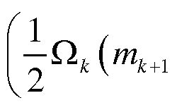
根据本发明的一个实施例, 所述步骤 (36) 中 通过计算 的特征值和特征向量, 得到第 + 1颗星参与计算的最优姿态四元素 ¾+ι/*+ι, 满足:
^-k+l/k+l^k+l/k+l = ^k+l/k+l^k+l/k+l 式
+ 1颗星参与姿态矩阵估计后的角速度如下: 式 25


其中, 表示姿态四元数 的矢量部分, ,^表示、四《元^数3^^ β的标量部分,通过获得 k+1/k+l 和^+1, 以进行下一次的预测递推。 本发明中涉及的基于卷帘曝光的星敏感器成像参数优化方法, 通过对星图中不同行之 间成像时刻的精密控制, 实现不同导航星点曝光时刻的精确分离, 弥补单帧星图中所有导 航星点曝光时刻相同导致动态信息缺失的不足, 并采用读出与曝光流水工作模式, 省去传
统的星敏感器读出时间。 基于此提出连续高动态的导航星点预测提取算法, 并提出卷帘曝 光模式下的单星递推姿态估计方法, 达到每提取一颗星完成一次当前时刻的姿态, 突破星 敏感器姿态确定以帧图像多矢量为基础的算法约束, 使更新率相对于传统算法提高一个量 级, 同时可以实现短时间内视场内只有 1颗星甚至无星时的姿态估计。 本发明突破了传统星敏感器工作过程中受到曝光与读出时间长、 动态性能差、 瞬时视 场精度不足、 系统更新率低的局限, 显著地提高星敏感器的性能。
在本说明书的描述中, 参考术语"一个实施例"、 "一些实施例"、 "示意性实施例"、 "示 例"、 "具体示例"、 或 "一些示例"等的描述意指结合该实施例或示例描述的具体特征、 结 构、 材料或者特点包含于本发明的至少一个实施例或示例中。 在本说明书中, 对上述术语 的示意性表述不一定指的是相同的实施例或示例。 而且, 描述的具体特征、 结构、 材料或 者特点可以在任何的一个或多个实施例或示例中以合适的方式结合。
尽管已经示出和描述了本发明的实施例, 本领域的普通技术人员可以理解: 在不脱 离本发明的原理和宗旨的情况下可以对这些实施例进行多种变化、 修改、 替换和变型, 本发明的范围由权利要求及其等同物限定。
Claims
权利要求书
1、 一种基于卷帘曝光成像的星敏感器的姿态确定方法, 其特征在于, 包括如下步骤: S 1 : 利用所述星敏感器内的图像传感器的、 基于行的卷帘曝光成像模式, 对用于卷帘 曝光成像的图像的曝光时间 ito、行读出时间 ^、行间积分间隔时间^和帧处理时间 之间 的关系进行优化;
S2 : 基于优化后的所述曝光时间 ito、 所述行读出时间 irf 、 所述行间积分间隔时间 ^.和 帧处理时间 之间的关系, 预测和提取所述星敏感器内的星图中所含有的 M个导航星点的 星点位置, 其中每个所述导航星点的星点位置可用于确定导航星点在所述星敏感器上的行 号以及
S3: 根据所述导航星点的星点位置并基于卷帘曝光的单星递推姿态估计, 每当提取一 颗导航星像点, 则更新一次所述星敏感器的姿态矩阵和角速度, 并将所述星敏感器的姿态 矩阵递推到下一颗导航星点的姿态矩阵计算中, 将下一颗导航星点的提取信息与递推获得 的所述姿态矩阵进行融合, 形成更新的所述星敏感器的所述姿态矩阵和所述角速度, 并依 次向下传递所述姿态矩阵和所述角速度, 直至获得所述星敏感器的最终姿态矩阵和最终角 速度。
2、 根据权利要求 1所述的姿态确定方法, 其特征在于, 在所述步骤 S 1中, 所述图 像传感器为设置在所述星敏感器内的具有卷帘曝光模式的 APS图像传感器。
3、 根据权利要求 2所述的姿态确定方法, 其特征在于, 所述图像传感器的总传感 器行数目为 n,且所述图像的每行的所述行读出时间 ^和所述行间积分间隔时间^相同, 且所述图像的所述曝光时间 tlnt满足下述公式:
4、 根据权利要求 3所述的姿态确定方法, 其特征在于, 在所述步骤 S 1中, 所述图 像传感器基于行依次进行循环曝光,且将经过曝光所获得的所述图像以所述行读出时间 ^进行依次循环读取, 并且对经过曝光所获得的所述图像的读取与对所述图像的曝光 同步进行, 其中
经过曝光所获得的所述图像的第一次读取时刻与所述图像传感器进行的所述图像 的第 n行的曝光的曝光时刻相同。
5、 根据权利要求 4所述的姿态确定方法, 其特征在于, 所述步骤 S2进一步包括:
S21 : 将所述星敏感器的姿态矩阵与提取第 k个导航星点的时间 tk组合, 以构成组合变 量
ARk≡ [ tk ] = [Ak mktri ]
其中, 表示提取第 个导航星点后计算得到的所述星敏感器的所述姿态矩阵, ^表 示被提取的第 个导航星点对应的曝光时刻, 表示第 个导航星点在所述图像传感器上 对应的行号;
S22 : 预测所述星敏感器的视场中的全部的所述 M个导航星点的星点位置; 以及 S23 : 基于所述 M个导航星点的预测位置, 设定 R0I窗口, 以对所述图像进行信号 提取。
6、 根据权利要求 5所述的姿态确定方法, 其特征在于, 所述步骤 S22进一步包括: S221 : 设定上一帧图像中第 M颗星位于第 m。行, 提取导航星点后获得的所述星敏感器 的所述姿态矩阵为 A, 估计得到所述星敏感器的所述角速度为 ;
S222: 当前帧图像的第 1颗星位于所述图像的 行, 提取该第 1颗星后获得的所述星 敏感器的所述姿态矩阵为 A, 估计得到所述星敏感器的所述角速度 为:

通过对当前图像中第 M颗星在所述图像传感器上的星点位置进行估计, 获得与所述第
M颗星相对应的预测位置 ( M , );
S223: 依次获得所述第 M个导航星点的、 与所述第 (M-1 )导航星点相对应的预测位 直 , 〜 , ,
S224: 基于所述 。和所述预测位置, 对当前帧图像中的第 Μ颗星的位置进行估计; S225: 根据与步骤 S221-S224相似的步骤, 依次获得其余的导航星点的预测位置。
7、 根据权利要求 1所述的姿态确定方法, 其特征在于, 所述步骤 S3包括:
( 531 ) 根据初始捕获算法获取所述图像的初始帧的姿态矩阵 、 特征矩阵 及姿态 角速度 ^, 记录所述导航星点的行号"
( 532 ) 提取第 + 1个导航星点, 所述导航星点所在的行号为《¾+1, 根据 ^及当前帧 导航星点行号" ¾、 当前帧导航星点与上一次姿态矩阵估计所用导航星点的曝光时间差, 计 算转移矩阵 Φ ,
( 533 ) 估计当前导航星点对应时刻的姿态四元数对应的特征矩阵 +ω:
( 534) 根据当前提取的导航星点矢量观测值及矢量参考值, 将提取出的第 + 1颗星 的测量矢量和参考矢量作为参数加入到所述星敏感器的所述姿态矩阵的估计, 并计算出第 + 1个导航星点^^ +1 ;
(535) 融融合步骤 S33、 S34中的数据, 以计算包含当前导航星点的四元数对应的特征 矩阵 k+1
其中, 0〈 〈1, 且表示当前导航星点矢量的权重系数;
(536) 根据 +1«+1计算最优的姿态四元数 及 λ+1, 返回执行步骤 S32, 以进行 所述星敏感器的下一次的递推及姿态矩阵估计。
8、 根据权利要求 7所述的姿态确定方法, 其特征在于, 所述步骤 S32中, 根据四元数 差分方程与角速度满足下述公式:
-[ΰίχ] ω
Ω =
-ω
4 = 2 q
其中, [ωχ]定义为:

为星敏感器的三轴角速度。
9、 根据权利要求 8所述的姿态确定方法, 其特征在于, 设置提取出第 颗星时估计的 姿态四元数为 , 角速度为 ^ = [^1' '«3 , 所述导航星点位于图像中第 行, 设置提取 了第 + 1颗星, 其位于图像中 行, 则从第 颗星到第 +1 颗星的时间间隔为 {mk+l -mk)tri ^ 得到
ί I \
φ +1 = e I (mk+1 - mk ) tn I
10、 根据权利要求 8所述的姿态确定方法, 其特征在于, 在所述步骤 S36中: 通过计算 的特征值和特征向量, 得到第 + 1颗导航星点参与计算的最优姿态四 兀素 +1/¾:+1, 且满足:

其中第 + 1颗导航星点参与姿态矩阵估计后的角速度为:
, 其中, 4表示姿


态四元数 的矢量部分, < ^表示四元数 的标量部分。
Priority Applications (1)
| Application Number | Priority Date | Filing Date | Title |
|---|---|---|---|
| US13/983,979 US9503653B2 (en) | 2013-02-18 | 2013-04-25 | Method for determining attitude of star sensor based on rolling shutter imaging |
Applications Claiming Priority (2)
| Application Number | Priority Date | Filing Date | Title |
|---|---|---|---|
| CN201310053052.0 | 2013-02-18 | ||
| CN201310053052.0A CN103148851B (zh) | 2013-02-18 | 2013-02-18 | 基于卷帘曝光成像的星敏感器的姿态确定方法 |
Publications (1)
| Publication Number | Publication Date |
|---|---|
| WO2014124574A1 true WO2014124574A1 (zh) | 2014-08-21 |
Family
ID=48547062
Family Applications (1)
| Application Number | Title | Priority Date | Filing Date |
|---|---|---|---|
| PCT/CN2013/074743 Ceased WO2014124574A1 (zh) | 2013-02-18 | 2013-04-25 | 基于卷帘曝光成像的星敏感器的姿态确定方法 |
Country Status (2)
| Country | Link |
|---|---|
| CN (1) | CN103148851B (zh) |
| WO (1) | WO2014124574A1 (zh) |
Cited By (2)
| Publication number | Priority date | Publication date | Assignee | Title |
|---|---|---|---|---|
| CN111412914A (zh) * | 2020-04-21 | 2020-07-14 | 中国科学院光电技术研究所 | 一种基于卷帘曝光帧间关联的星敏感器提高姿态更新率方法 |
| CN117553778A (zh) * | 2023-12-03 | 2024-02-13 | 北京航空航天大学 | 一种编码成像星敏感器、动态测量精度提升方法和系统 |
Families Citing this family (16)
| Publication number | Priority date | Publication date | Assignee | Title |
|---|---|---|---|---|
| CN103487058B (zh) * | 2013-09-06 | 2016-08-17 | 北京控制工程研究所 | 一种提高aps星敏感器动态性能的方法 |
| CN103791902B (zh) * | 2014-01-23 | 2016-08-17 | 中国科学院长春光学精密机械与物理研究所 | 适用于高机动载体的星敏感器自主导航方法 |
| CN106382928B (zh) * | 2016-08-26 | 2019-05-24 | 北京控制工程研究所 | 一种基于卷帘曝光星敏感器的动态补偿方法 |
| CN108040212B (zh) * | 2017-11-29 | 2019-12-31 | 长光卫星技术有限公司 | 基于交错卷帘快门的高精度目标跟踪方法 |
| CN107942090B (zh) * | 2017-12-28 | 2019-10-29 | 北京航空航天大学 | 一种基于模糊星图提取光流信息的航天器角速度估计方法 |
| CN108759818B (zh) * | 2018-04-26 | 2021-10-15 | 上海微小卫星工程中心 | 一种超高精度导星敏感器姿态确定的方法 |
| CN109489656B (zh) * | 2018-09-30 | 2020-10-27 | 南京航空航天大学 | 基于旋量的星敏定姿方法 |
| CN110198415B (zh) * | 2019-05-26 | 2021-08-24 | 初速度(苏州)科技有限公司 | 一种图像时间戳的确定方法和装置 |
| CN111121756B (zh) * | 2019-07-16 | 2021-12-07 | 上海航天控制技术研究所 | 一种高动态星敏感器图像处理控制方法 |
| CN110514187B (zh) * | 2019-08-30 | 2023-01-06 | 北京航空航天大学 | 一种小视场相机天文找北技术方法及装置 |
| CN110677594B (zh) * | 2019-10-11 | 2020-08-25 | 北京富吉瑞光电科技有限公司 | 一种光电周视成像系统的补偿成像方法及装置 |
| CN111412915B (zh) * | 2020-04-21 | 2022-08-26 | 中国科学院光电技术研究所 | 一种基于平均速度的卷帘曝光星敏感器星点位置校正方法 |
| CN114088060B (zh) * | 2020-08-24 | 2024-04-30 | 中国科学院长春光学精密机械与物理研究所 | 一种用于光学遥感卫星指向测量的星地相机成像系统 |
| CN112437206B (zh) * | 2020-11-25 | 2022-07-29 | 杭州海康威视数字技术股份有限公司 | 补光控制方法和摄像机 |
| CN116485705A (zh) * | 2022-12-09 | 2023-07-25 | 华中光电技术研究所(中国船舶集团有限公司第七一七研究所) | 一种核辐射中子损伤星敏感器预处理方法 |
| CN119289970B (zh) * | 2024-10-10 | 2025-04-29 | 哈尔滨工业大学 | 一种采用国产卷帘式曝光探测器的星敏感器时间控制方法 |
Citations (4)
| Publication number | Priority date | Publication date | Assignee | Title |
|---|---|---|---|---|
| JP2006010418A (ja) * | 2004-06-24 | 2006-01-12 | Nec Engineering Ltd | 恒星センサ |
| CN101435704A (zh) * | 2008-12-04 | 2009-05-20 | 哈尔滨工业大学 | 一种星敏感器高动态下的星跟踪方法 |
| CN101907463A (zh) * | 2010-07-05 | 2010-12-08 | 中国人民解放军国防科学技术大学 | 一种星敏感器恒星像点位置提取方法 |
| CN102117199A (zh) * | 2011-01-14 | 2011-07-06 | 哈尔滨工业大学 | 利用并行流水线机制提高星敏感器数据更新率的方法 |
Family Cites Families (1)
| Publication number | Priority date | Publication date | Assignee | Title |
|---|---|---|---|---|
| JP3034807B2 (ja) * | 1996-08-30 | 2000-04-17 | 三菱電機株式会社 | 人工衛星の姿勢決定装置 |
-
2013
- 2013-02-18 CN CN201310053052.0A patent/CN103148851B/zh active Active
- 2013-04-25 WO PCT/CN2013/074743 patent/WO2014124574A1/zh not_active Ceased
Patent Citations (4)
| Publication number | Priority date | Publication date | Assignee | Title |
|---|---|---|---|---|
| JP2006010418A (ja) * | 2004-06-24 | 2006-01-12 | Nec Engineering Ltd | 恒星センサ |
| CN101435704A (zh) * | 2008-12-04 | 2009-05-20 | 哈尔滨工业大学 | 一种星敏感器高动态下的星跟踪方法 |
| CN101907463A (zh) * | 2010-07-05 | 2010-12-08 | 中国人民解放军国防科学技术大学 | 一种星敏感器恒星像点位置提取方法 |
| CN102117199A (zh) * | 2011-01-14 | 2011-07-06 | 哈尔滨工业大学 | 利用并行流水线机制提高星敏感器数据更新率的方法 |
Non-Patent Citations (3)
| Title |
|---|
| LUO, CHANGZHOU ET AL.: "Improving Data Update Speed of Star Sensor", JOURNAL OF APPLIED OPTICS, vol. 34, no. 1, January 2013 (2013-01-01), pages 111 - 116 * |
| MAO, XIAONAN ET AL.: "A Parallel Computing Architecture Based Image Processing Algorithm for Star Sensor", JOURNAL OF ASTRONAUTICS, vol. 32, no. 3, March 2011 (2011-03-01), pages 613 - 619 * |
| WANG, KE ET AL.: "Design and Implementation of Driving Timing for CMOS APS Image Sensor", PROCEEDINGS OF THE FOURTH ACADEMIC ANNUAL COFERENCE OF COMMITTEE OF DEEP SPACE EXPLORATION TECHNOLOGY, CHINESE SOCIETY OF ASTRONAUTICS, vol. 21, June 2007 (2007-06-01), pages 213 - 218 * |
Cited By (3)
| Publication number | Priority date | Publication date | Assignee | Title |
|---|---|---|---|---|
| CN111412914A (zh) * | 2020-04-21 | 2020-07-14 | 中国科学院光电技术研究所 | 一种基于卷帘曝光帧间关联的星敏感器提高姿态更新率方法 |
| CN111412914B (zh) * | 2020-04-21 | 2022-08-23 | 中国科学院光电技术研究所 | 一种基于卷帘曝光帧间关联的星敏感器提高姿态更新率方法 |
| CN117553778A (zh) * | 2023-12-03 | 2024-02-13 | 北京航空航天大学 | 一种编码成像星敏感器、动态测量精度提升方法和系统 |
Also Published As
| Publication number | Publication date |
|---|---|
| CN103148851A (zh) | 2013-06-12 |
| CN103148851B (zh) | 2015-06-24 |
Similar Documents
| Publication | Publication Date | Title |
|---|---|---|
| WO2014124574A1 (zh) | 基于卷帘曝光成像的星敏感器的姿态确定方法 | |
| US9503653B2 (en) | Method for determining attitude of star sensor based on rolling shutter imaging | |
| CN109540126B (zh) | 一种基于光流法的惯性视觉组合导航方法 | |
| CN112461210B (zh) | 一种空地协同建筑测绘机器人系统及其测绘方法 | |
| CN106017463A (zh) | 一种基于定位传感装置的飞行器定位方法 | |
| CN103903263B (zh) | 一种基于Ladybug全景相机图像的360度全方位测距方法 | |
| CN105160703A (zh) | 一种使用时域视觉传感器的光流计算方法 | |
| CN111091088B (zh) | 一种视频卫星信息支援海上目标实时检测定位系统及方法 | |
| CN111504312A (zh) | 一种基于视觉惯性偏振光融合的无人机位姿估计方法 | |
| CN107478220A (zh) | 无人机室内导航方法、装置、无人机及存储介质 | |
| CN106813662A (zh) | 一种基于光流的导航方法 | |
| CN108827341A (zh) | 用于确定图像采集装置的惯性测量单元中的偏差的方法 | |
| Yan et al. | Long-term visual localization with mobile sensors | |
| CN106023192A (zh) | 一种图像采集平台的时间基准实时标定方法及系统 | |
| CN108253962A (zh) | 一种低照度环境下新能源无人驾驶汽车定位方法 | |
| CN108801250B (zh) | 基于水下机器人的实时姿态获取方法及装置 | |
| CN115049795B (zh) | 一种基于影像外方位元素的三维结构重建装置及方法 | |
| CN114993306B (zh) | 一种尺度自恢复的视觉惯性组合导航方法和装置 | |
| CN120403648B (zh) | 一种基于模型误差学习的偏振/惯性/视觉智能导航方法 | |
| CN113902859B (zh) | 一种单目相机成像半稠密建图方法、存储介质及装置 | |
| CN119803463A (zh) | 水下机器人定位方法及系统 | |
| JP4361913B2 (ja) | 動き量計算装置 | |
| CN117519256B (zh) | 一种无人机平台单目轨迹重构方法 | |
| Zhou et al. | Data collection and alignment algorithms for data-driven inertial navigation | |
| CN113628279B (zh) | 一种全景视觉slam建图方法 |
Legal Events
| Date | Code | Title | Description |
|---|---|---|---|
| WWE | Wipo information: entry into national phase |
Ref document number: 13983979 Country of ref document: US |
|
| 121 | Ep: the epo has been informed by wipo that ep was designated in this application |
Ref document number: 13874932 Country of ref document: EP Kind code of ref document: A1 |
|
| NENP | Non-entry into the national phase |
Ref country code: DE |
|
| 122 | Ep: pct application non-entry in european phase |
Ref document number: 13874932 Country of ref document: EP Kind code of ref document: A1 |