WO2014104211A1 - Seat device - Google Patents
Seat device Download PDFInfo
- Publication number
- WO2014104211A1 WO2014104211A1 PCT/JP2013/084939 JP2013084939W WO2014104211A1 WO 2014104211 A1 WO2014104211 A1 WO 2014104211A1 JP 2013084939 W JP2013084939 W JP 2013084939W WO 2014104211 A1 WO2014104211 A1 WO 2014104211A1
- Authority
- WO
- WIPO (PCT)
- Prior art keywords
- support leg
- reinforcing
- wall
- seat device
- extending
- Prior art date
Links
Images


Classifications
-
- B—PERFORMING OPERATIONS; TRANSPORTING
- B60—VEHICLES IN GENERAL
- B60N—SEATS SPECIALLY ADAPTED FOR VEHICLES; VEHICLE PASSENGER ACCOMMODATION NOT OTHERWISE PROVIDED FOR
- B60N2/00—Seats specially adapted for vehicles; Arrangement or mounting of seats in vehicles
- B60N2/02—Seats specially adapted for vehicles; Arrangement or mounting of seats in vehicles the seat or part thereof being movable, e.g. adjustable
- B60N2/04—Seats specially adapted for vehicles; Arrangement or mounting of seats in vehicles the seat or part thereof being movable, e.g. adjustable the whole seat being movable
- B60N2/06—Seats specially adapted for vehicles; Arrangement or mounting of seats in vehicles the seat or part thereof being movable, e.g. adjustable the whole seat being movable slidable
- B60N2/07—Slide construction
- B60N2/0722—Constructive details
- B60N2/073—Reinforcement members preventing slide dislocation
-
- B—PERFORMING OPERATIONS; TRANSPORTING
- B60—VEHICLES IN GENERAL
- B60N—SEATS SPECIALLY ADAPTED FOR VEHICLES; VEHICLE PASSENGER ACCOMMODATION NOT OTHERWISE PROVIDED FOR
- B60N2/00—Seats specially adapted for vehicles; Arrangement or mounting of seats in vehicles
- B60N2/005—Arrangement or mounting of seats in vehicles, e.g. dismountable auxiliary seats
- B60N2/015—Attaching seats directly to vehicle chassis
-
- B—PERFORMING OPERATIONS; TRANSPORTING
- B60—VEHICLES IN GENERAL
- B60N—SEATS SPECIALLY ADAPTED FOR VEHICLES; VEHICLE PASSENGER ACCOMMODATION NOT OTHERWISE PROVIDED FOR
- B60N2/00—Seats specially adapted for vehicles; Arrangement or mounting of seats in vehicles
- B60N2/02—Seats specially adapted for vehicles; Arrangement or mounting of seats in vehicles the seat or part thereof being movable, e.g. adjustable
- B60N2/04—Seats specially adapted for vehicles; Arrangement or mounting of seats in vehicles the seat or part thereof being movable, e.g. adjustable the whole seat being movable
- B60N2/06—Seats specially adapted for vehicles; Arrangement or mounting of seats in vehicles the seat or part thereof being movable, e.g. adjustable the whole seat being movable slidable
- B60N2/067—Seats specially adapted for vehicles; Arrangement or mounting of seats in vehicles the seat or part thereof being movable, e.g. adjustable the whole seat being movable slidable by linear actuators, e.g. linear screw mechanisms
-
- B—PERFORMING OPERATIONS; TRANSPORTING
- B60—VEHICLES IN GENERAL
- B60N—SEATS SPECIALLY ADAPTED FOR VEHICLES; VEHICLE PASSENGER ACCOMMODATION NOT OTHERWISE PROVIDED FOR
- B60N2/00—Seats specially adapted for vehicles; Arrangement or mounting of seats in vehicles
- B60N2/02—Seats specially adapted for vehicles; Arrangement or mounting of seats in vehicles the seat or part thereof being movable, e.g. adjustable
- B60N2/04—Seats specially adapted for vehicles; Arrangement or mounting of seats in vehicles the seat or part thereof being movable, e.g. adjustable the whole seat being movable
- B60N2/06—Seats specially adapted for vehicles; Arrangement or mounting of seats in vehicles the seat or part thereof being movable, e.g. adjustable the whole seat being movable slidable
- B60N2/07—Slide construction
- B60N2/075—Slide construction roller-less
Definitions
- the present invention relates to a seat device, and more particularly to a seat device mounted on a vehicle.
- support legs a front leg portion 71 and a rear leg portion 72
- support legs are provided at respective front and rear ends of a slide rail for sliding a seat body.
- a reinforcing portion (side plates 73 and 74) made of a plate material is provided between the front supporting leg and the rear supporting leg, and the front supporting leg and the rear supporting leg are connected by the reinforcing portion.
- the bead (riser reinforcement part 73a) along the front-back direction is provided in the reinforcement part.
- an object of the present invention is to increase the strength of the support legs by making the connection state between the front support legs and the rear support legs more rigid.
- a seat device for supporting the seat body slidably in the front-rear direction; A front support leg fixed to the front end of the slide part; A rear support leg fixed to the rear end of the slide part; A reinforcing portion spanned between the front support leg and the rear support leg, The reinforcing part is A first wall portion attached to one side of the front support leg and the rear support leg; A second wall part attached to the other side of the front support leg and the rear support leg and facing the first wall part; It has the 1st connection part which connects between the lower part of said 1st wall part and said 2nd wall part, It is characterized by the above-mentioned.
- the invention according to claim 2 is the seat apparatus according to claim 1,
- the reinforcing portion includes a second connecting portion that connects upper portions of the first wall portion and the second wall portion.
- the invention according to claim 3 is the seat apparatus according to claim 2, There are a plurality of the first connecting portions, Said 2nd connection part is arrange
- the front and rear end portions of the reinforcing portion are widened portions that are longer in the vertical direction than the central portion of the reinforcing portion.
- the invention according to claim 5 is the seat device according to claim 4, Said 1st connection part is arrange
- the invention according to claim 6 is the seat device according to any one of claims 1 to 5,
- the upper wall and the lower edge of each of the first wall and the second wall are provided with ribs extending inward.
- the invention according to claim 7 is the seat device according to claim 6,
- the ribs at the lower edge portions of the first wall portion and the second wall portion are continuous with the first connecting portion.
- the invention according to claim 8 is the seat device according to any one of claims 1 to 7,
- the reinforcing part is It is characterized in that the front support leg is disposed at a distance from a fixed part of the front support leg with the slide part and a fixed part of the rear support leg with the slide part.
- the invention according to claim 9 is the seat device according to claim 8, A portion of the reinforcing portion that faces the fixed portion is open.
- the invention according to claim 10 is the seat device according to any one of claims 1 to 9,
- the reinforcing portion is provided with another member attaching portion for attaching another member.
- the invention according to claim 11 is the seat device according to claim 10,
- the other member is a cover member that covers the reinforcing part and the attaching part of the reinforcing part and the support leg.
- the invention according to claim 12 is the seat device according to claim 10 or 11, A plurality of the other member mounting portions are provided with respect to the reinforcing portion, The reinforcing portion is provided with beads extending in the front-rear direction so as to face the plurality of other member mounting portions.
- the invention according to claim 13 is the seat apparatus according to claim 12, Both end portions before and after the reinforcing portion are widened portions having a width in the vertical direction longer than the central portion of the reinforcing portion, The bead extends to the widened portion.
- the invention according to claim 14 is the seat device according to claim 12 or 13, The bead is provided at a position corresponding to the first connecting portion.
- the invention according to claim 15 is the seat apparatus according to any one of claims 1 to 14, A drive device is arranged in a space between the slide part and the reinforcing part.
- the invention according to claim 16 is the seat device according to any one of claims 1 to 15, The first wall portion and the second wall portion have the same shape.
- the invention according to claim 17 is the seat device according to any one of claims 1 to 16, Of the left and right slide parts, the reinforcing part is provided only on the front support leg and the rear support leg of one slide part,
- the rear support leg of the other slide part is A base fixed to overlap the other slide part;
- An extending fixing portion that is suspended from the base so as to face the extending floor surface extending downward from the horizontal plane, and is fixed to the extending floor surface;
- a restricting portion fixed to the slide portion so as to press the front surface portion of the extending fixing portion.
- the invention according to claim 18 is the seat device according to claim 17,
- the regulation part is An upper surface portion overlapping the slide portion;
- the upper surface portion is provided with a recess,
- the concave portion faces the front surface portion of the extending fixing portion,
- the concave portion and the front surface portion are fixed by welding.
- the invention according to claim 19 is the seat device according to claim 18,
- the regulation part is A wall portion depending from the upper surface portion; And an extending portion extending outward from the lower end portion of the wall portion.
- the invention according to claim 20 is the seat device according to claim 19,
- the regulation part is It is characterized by comprising a drooping portion that continuously hangs down from the extending portion and is welded facing the front surface portion of the extending fixing portion.
- the first connection portion is provided.
- the strength of the first wall portion and the second wall portion is increased by the portion.
- the rigidity of the reinforcing portion can be increased by the second connecting portion.
- the front and rear end portions of the reinforcing portion are widened portions having a width in the vertical direction longer than the central portion of the reinforcing portion, the joining to the front support leg and the rear support leg is performed.
- the area can be increased, and the attachment rigidity when attached to the front support leg and the rear support leg can be increased.
- the first connecting portion since the first connecting portion is disposed closer to the center than the widened portion before and after the reinforcing portion, the first connecting portion reinforces the portion having a lower strength than the widened portion. As a result, the strength of the entire reinforcing portion can be increased.
- the ribs extending inward are provided on the upper edge portion and the lower edge portion of each of the first wall portion and the second wall portion, the ribs are reinforced by the ribs. The rigidity of the part is increased.
- the reinforcing portion is disposed with a space between the fixed portion of the front support leg and the slide portion and the fixed portion of the rear support leg and the slide portion,
- Each support leg can be assembled to the slide portion by using. Therefore, it is possible to easily assemble the slide portion and the respective support legs even when there is no interval.
- the tool since the portion of the reinforcing portion that faces the fixed portion is opened, the tool can be easily engaged with the fixed portion through the opening, and the attachment property can be improved.
- the reinforcing portion and the other member mounting portion are integrated to increase the strength of the reinforcing portion.
- the mounting rigidity of the other members can be improved.
- the other member is a cover member that covers the reinforcing portion and the mounting portion of the reinforcing portion and the support leg. Can do well.
- the bead extending in the front-rear direction is provided in the reinforcing portion so as to face the plurality of other member mounting portions, the strength in the vicinity of the other member mounting portion is increased by the beads.
- the stability of the other member mounting portion can be further enhanced.
- the bead is provided at a position corresponding to the first connecting portion, the rigidity of the reinforcing portion can be further increased by the bead.
- the driving device since the driving device is disposed in the space between the slide portion and the reinforcing portion, the driving device can be disposed in the dead space, and an increase in the size of the seat device is suppressed. be able to.
- first wall portion and the second wall portion have the same shape, parts can be shared.
- the rear support leg of the other slide part not provided with the reinforcing part is provided with the restricting part fixed to the slide part so as to press the front part of the extension fixing part. Therefore, the support force of the slide part in the rear support leg can be increased.
- the restricting portion and the extending fixing portion are provided while suppressing an increase in size of the support leg. Can be integrated.
- the restricting portion includes the wall portion depending from the upper surface portion and the extending portion extending outward from the lower end portion of the wall portion. Stiffness can be increased.
- the restricting portion and the extending fixing portion are integrated over a wider range.
- the mounting rigidity can be further increased.
- FIG. 3 is a top view of a part of the left leg portion of FIG. 2 as viewed from above. It is the bottom view which looked at a part of left leg part of Drawing 2 from the bottom. It is a perspective view which shows schematic structure of the cover member which concerns on this embodiment. It is a perspective view which shows the cover member attached to the left leg part concerning this embodiment. It is a side view which shows schematic structure of the right leg part which concerns on this embodiment. It is the perspective view which looked at the back support leg concerning this embodiment from the slanting upper part. It is the perspective view which looked at the back support leg of FIG. 9 from diagonally downward.
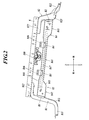
- FIG. 1 is a perspective view showing a main part configuration of a sheet apparatus according to the present embodiment.
- the seat device 1 includes a seat body 90, a pair of left and right slide portions 60 that support the seat body 90 so as to be slidable in the front-rear direction, and a pair of left and right slide portions 60 fixed to the vehicle floor. And a leg portion 7 for carrying out the operation.
- the seat body 90 includes a seat back frame 2, a pair of left and right cushion side frames 3 disposed on the left and right of the lower portion of the seat back frame 2, and a reclining mechanism that tilts the seat back frame 2 with respect to the cushion side frame 3. 4 is provided.
- the slide portion 60 includes an upper rail 5 that supports the left and right cushion side frames 3, and a lower rail 6 that supports the upper rail 5 in a slidable manner and has leg portions 7 attached thereto.
- the leg portion 7 includes a left leg portion 8 that supports the left slide portion 60 and a right leg portion 9 that supports the right slide portion 60.
- a left leg portion 8 that supports the left slide portion 60
- a right leg portion 9 that supports the right slide portion 60.
- the floor surface on which the left leg portion 8 is installed is lower and the floor surface on which the right leg portion 9 is installed is higher will be described as an example.
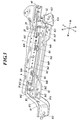
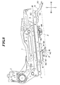
- FIG. 2 is a side view showing a schematic configuration of the left leg 8.
- FIG. 3 is a perspective view showing a schematic configuration of the left leg 8.
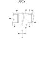
- FIG. 4 is a top view of a part of the left leg 8 as seen from above.
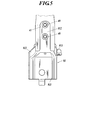
- FIG. 5 is a bottom view of a part of the left leg of FIG. 2 as viewed from below.
- the left leg 8 has a front support leg 81 fixed to the front end of the lower rail 6, a rear support leg 82 fixed to the rear end of the lower rail 6, and a front support.
- a reinforcing portion 83 is provided between the leg 81 and the rear support leg 82.
- a floor fixing portion 811 that extends toward the front and is fixed to the floor surface of the vehicle is provided at the lower end portion of the front support leg 81.
- a rail fixing portion 812 that extends rearward and is fixed to the lower rail 6 is provided at the upper end portion of the front support leg 81 so as to overlap the lower surface of the front end portion of the lower rail 6.
- ribs 813 and 814 are formed on each of the left and right side portions of the front support leg 81 so as to be continuously provided on the floor surface side from the floor fixing portion 811 to the rail fixing portion 812.
- a floor fixing portion 821 that extends rearward and is fixed to the floor surface of the vehicle is provided at the lower end portion of the rear support leg 82.
- a rail fixing portion 822 that extends forward and is fixed to the lower rail 6 is provided at the upper end portion of the rear support leg 82 so as to overlap the lower surface of the rear end portion of the lower rail 6.
- ribs 823 and 824 are formed on each of the left and right side portions of the rear support leg 82 so as to stand on the floor surface continuously from the floor fixing portion 821 to the rail fixing portion 822.
- the rail fixing portion 812 of the front support leg 81 is fixed to the lower rail 6 by a fixing tool 40 such as a screw (see FIG. 5). Although not shown, the same applies to the rail fixing portion 822 of the rear support leg 82.
- the reinforcing portion 83 is arranged at intervals in the vertical direction with respect to the ribs 813, 814, 823, and 824 in the floor fixing portions 811 and 821 of both the front support leg 81 and the rear support leg 82.
- the reinforcing portion 83 is attached to the first wall 84 attached to the left side of the front support leg 81 and the rear support leg 82, and to the right side of the front support leg 81 and the rear support leg 82.
- 84, and a second wall portion 85 that opposes 84 are attached to the first wall 84 attached to the left side of the front support leg 81 and the rear support leg 82, and to the right side of the front support leg 81 and the rear support leg 82.
- the front end portion of the first wall portion 84 is disposed on the inner side (right side) of the left rib 813 of the front support leg 81, and is fixed to the outer surface of the rib 813 by welding.
- the rear end portion of the first wall portion 84 is disposed inside the left rib 823 of the rear support leg 82 and is fixed to the outer surface of the rib 823 by welding.
- the welding locations are indicated by reference numerals B1 and B2 in FIGS.
- the front end portion of the second wall portion 85 is disposed on the inner side (left side) of the right rib 814 of the front support leg 81, and is fixed to the outer surface of the rib 814 by welding.
- the rear end portion of the second wall portion 85 is disposed inside the right rib 824 of the rear support leg 82 and is fixed to the outer surface of the rib 824 by welding.
- the first wall portion 84 and the second wall portion 85 are disposed inside the left and right ribs 813 and 814 of the front support leg 81 and are disposed inside the left and right ribs 823 and 824 of the rear support leg 82. Therefore, the reinforcing portion 83 can be installed in a compact manner.
- the 1st wall part 84 and the 2nd wall part 85 are substantially the same shape, in the following description, the 1st wall part 84 is demonstrated and about the 2nd wall part 85, each part of the 1st wall part 84 Descriptions are omitted by attaching the same reference numerals to the portions corresponding to.
- the first wall portion 84 is continuous with the central portion 841 and the front side of the central portion 841, and is continuous with the front widened portion 842 having a longer vertical width than the central portion 841 and the rear side of the central portion 841.
- a rear widened portion 843 having a width in the vertical direction longer than that of the central portion 841.
- the front widened portion 842 extends to the center portion 841 side from the rail fixing portion 812 of the front support leg 81. Further, the rear widened portion 843 extends to the center portion 841 side from the rail fixing portion 822 of the rear support leg 82.
- a rib 844 extending inward is formed continuously from the front end to the rear end.
- a rib 845 extending inward is continuously formed on the lower edge portion of the first wall portion 84 from the front end portion to the rear end portion. Since the ribs 844 and 845 extending inwardly are also provided on the upper edge and the lower edge of the second wall 85, the ribs 844 and 845 of the first wall 84 and the second wall 85 The ribs 844 and 845 face each other, and the rigidity of the entire reinforcing portion 83 can be increased.
- the upper edge portion of the center portion 841 is provided at a position lower than the upper edge portions of the front widened portion 842 and the rear widened portion 843.
- the lower edge portion of the central portion 841 is provided at a position higher than the lower edge portions of the front widened portion 842 and the rear widened portion 843. These boundaries are tapered.
- Two other member attachment portions 846 for attaching other members are attached to the outer surface of the upper edge portion of the central portion 841 by welding at a predetermined interval in the front-rear direction. The welding location of the other member attaching portion 846 is indicated by reference numerals B3 and B4 in FIGS.
- the other member mounting portion 846 is disposed at a position not facing the rail fixing portion 812 of the front support leg 81 and the rail fixing portion 822 of the rear support leg 82, the front support leg 81, the rear support leg 82, and the other members are arranged. It can suppress that the attachment part 846 and the other member attached to the said other member attachment part 846 interfere.
- examples of the other member include a cover member 45 attached to the left leg 8.
- FIG. 6 is a perspective view showing a schematic configuration of the cover member 45
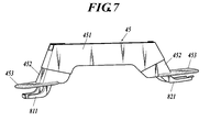
- FIG. 7 is a perspective view showing the cover member 45 attached to the left leg portion 8.
- the cover member 45 includes a first cover portion 451 that extends in the front-rear direction and covers the upper portions of the front support legs 81 and the rear support legs 82 and the reinforcing portions 83, and a first cover portion 451.
- a pair of front and rear second cover portions 452 extending downward from the front end portion and rear end portion of the front cover to cover the lower portions of the front support legs 81 and the rear support legs 82, and forward from the lower ends of the pair of front and rear second cover portions 452
- a pair of front and rear third cover portions 453 that extend rearward and cover the floor fixing portions 811 and 821 are provided.
- the first cover part 451, the second cover part 452, and the third cover part 453 are separate bodies, and the cover member 45 is formed by assembling them together.
- claw portions 46 that are respectively engaged with the two other member attachment portions 846 are provided.
- the cover member 45 By engaging the claw portion 46 with the other member attaching portion 846, the cover member 45 is made to have the reinforcing portion 83, the attaching portion of the reinforcing portion 83 and the supporting legs 81 and 82, and the lower rail as shown in FIG. 6 will be covered.
- the cover member 45 shown in FIGS. 6 and 7 the case where the third cover part 453 covers only the upper part of the floor fixing parts 811 and 821 is illustrated, but the third cover part 453 is the floor fixing part 811. , 821 may be covered. As a result, the entire front support leg 81 and the rear support leg 82 are covered with the cover member 45.
- the lower rail 6 is fixed to the lower end surface.
- a driving device 100 such as a motor is disposed.
- a bead 847 extending in the front-rear direction is formed on the first wall portion 84 so as to face the plurality of other member mounting portions 846.
- the bead 847 extends in the front-rear direction more than between the plurality of other member mounting portions 846, and both end portions thereof enter the front widened portion 842 and the rear widened portion 843. Accordingly, the front end portion of the bead 847 is disposed at a position facing the rail fixing portion 812 of the front support leg 81, and the rear end portion of the bead 847 is disposed at a position facing the rail fixing portion 822 of the rear support leg 82. Is done.
- the first wall portion 84 and the second wall portion 85 are provided with a pair of first connection portions 848 that connect the lower end portions and a second connection portion 849 that connects the upper end portions. Yes.
- the pair of first connecting portions 848 is provided so as to be bridged in the left-right direction between the lower ends of the central portions 841 and 841 of the first wall portion 84 and the second wall portion 85.
- the pair of first connecting portions 848 is disposed in the vicinity of the outside of the plurality of other member attaching portions 846. Thereby, the force applied to each other member attachment portion 846 can be dispersed also to the pair of first connection portions 848, and the strength of the other member attachment portion 846 can be increased.
- the second connecting portion 849 is provided so as to be bridged in the left-right direction between the upper ends of the central portions 841 and 841 of the first wall portion 84 and the second wall portion 85.
- the second connection portion 849 is disposed between the pair of first connection portions 848.
- an opening 41 is provided so as to expose the fixture 40 of the rail fixing portion 812 from the lower surface (see FIG. 5). That is, the portion of the reinforcing portion 83 that faces the fixed portion is open.
- FIG. 8 is a side view showing a schematic configuration of the right leg portion 9.
- the right leg portion 9 includes a front support leg 91 fixed to the front end portion of the lower rail 6 and a rear support leg 92 fixed to the rear end portion of the lower rail 6.
- the driving device 100 is disposed between the front support legs 91 and the rear support legs 92 and in a space formed by the floor surface F and the lower rail 6.
- a floor fixing portion 911 that extends forward and is fixed to the floor surface F of the vehicle is provided.
- a rail fixing portion 912 that extends rearward and is fixed to the lower rail 6 is provided at the upper end portion of the front support leg 91 so as to overlap the lower surface of the front end portion of the lower rail 6.
- ribs 913 are formed so as to stand on the floor surface side continuously from the floor fixing portion 911 to the rail fixing portion 912.
- FIG. 9 is a perspective view of the rear support leg 92 seen from obliquely above
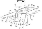
- FIG. 10 is a perspective view of the rear support leg 92 seen obliquely from below.
- the rear support leg 92 is suspended from the base so as to face the base 93 fixed to overlap the lower rail 6 on the right side and the extended floor surface f ⁇ b> 1 substantially orthogonal to the horizontal plane.
- an extension fixing portion 94 fixed to the extension floor surface f1 and a restriction portion 95 fixed to the lower rail 6 so as to press the front surface portion 941 of the extension fixing portion 94 are provided.
- the extended floor surface f1 may extend downward from the horizontal plane at an angle other than substantially orthogonal to the horizontal plane. In this case, it is preferable that the extending fixing portion 94 is extended so as to correspond to the inclination of the extended floor surface f1.
- the base portion 93 has an upper surface portion 931 that overlaps the lower surface of the lower rail 6, a pair of wall portions 932 that hang down from the left and right of the upper surface portion 931, and extends outward from the lower end portion of the wall portion 932, And an extending portion 933 that overlaps.
- Two through holes 934 are formed in the upper surface portion 931 at a predetermined interval in the front-rear direction, and a fixing tool such as a screw is inserted into the through hole 934 and locked to the lower rail 6, thereby 93 can be fixed to the lower rail 6.
- the extending fixing portion 94 extends rearward from the front surface portion 941 so as to continuously extend from the upper surface portion 931 and to the front surface portion 941 facing the extended floor surface f1 and the wall portion 932 of the base portion 93. And a wall portion 942 extending from the rear end portion to the outside so as to be continuous with the extending portion 933 of the base portion 93, and an extending portion 943 overlapping the extended floor surface f1. .
- a through hole 944 is formed in the front surface portion 941, and a fixing tool such as a screw is inserted into the through hole 944 and locked to the extended floor surface f1, whereby the base portion 93 and the extension fixing portion 94 are provided. Can be fixed to the floor F.
- the restricting portion 95 extends outward from the lower end portion of the wall portion 952 and the upper surface portion 951 that overlaps the lower surface of the lower rail 6, the pair of wall portions 952 that hang from the left and right of the upper surface portion 951, and on the floor surface F.
- the extending part 953 which overlaps, and the hanging part 954 continuously hung from the rear-end part of the extending part 953, and was welded facing the extending part 943 of the fixing part 94 for extension are provided.
- the welding location between the drooping portion 954 and the extending portion 943 is indicated by the symbol B5 in FIGS.
- a through hole 955 is formed in the upper surface portion 951, and a restricting portion 95 can be fixed to the lower rail 6 by inserting a fixing tool such as a screw into the through hole 955 and locking it to the lower rail 6. ing.
- a concave portion 956 is formed at the rear end portion of the upper surface portion 951 so as to gradually lower toward the rear. The rear end portion of the recessed portion 956 faces the front surface portion 941 of the extending fixing portion 94, and the recessed portion 956 and the front surface portion 941 are fixed by welding. This welding location is indicated by the symbol B6 in FIGS.
- the first wall 84 and the second wall 85 facing each other of the reinforcing portion 83 are provided with the first connection portion 848 that connects the lower ends thereof. Therefore, the strength of the first wall portion 84 and the second wall portion 85 is increased by the first connecting portion 848. Thereby, the connection state of the front support leg 81 and the back support leg 82 will also be raised, and the intensity
- the 2nd connection part 849 which connects between the upper part of the 1st wall part 84 and the 2nd wall part 85 is provided, the 1st wall part 84 and the 2nd wall part 85 of this 2nd connection part 849 are provided. The strength can be further increased. Further, since the second connecting portion 849 is disposed between the plurality of first connecting portions 848, the rigidity of the reinforcing portion 83 can be increased by the second connecting portion 849.
- both the front and rear ends of the reinforcing portion 83 are widened portions (front widened portion 842 and rear widened portion 843) that are longer in the vertical direction than the central portion 841, the front support leg 81 and the rear support leg.
- the joining area with respect to 82 can be increased, and the attachment rigidity when attached to the front support leg 81 and the rear support leg 82 can be increased.
- the central portion 841 having a lower strength than the front widened portion 842 and the rear widened portion 843 is the first. It will be reinforced by the connection part 848, and the intensity
- ribs 844 and 845 extending inward are provided at the upper and lower edge portions of the first wall portion 84 and the second wall portion 85, respectively.
- the rigidity of the portion 83 is increased.
- the rib 845 at the lower edge of the first wall portion 84 and the second wall portion 85 is continuous with the first connecting portion 848, the rib 845 and the first connecting portion 848 are integrated, and the reinforcing portion 83.
- the rigidity of can be further increased.
- the reinforcing portion 83 is disposed with a space between the fixing portion (rail fixing portion 812) of the front support leg 81 to the lower rail 6 and the fixing portion (rail fixing portion 822) of the rear support leg 82 to the lower rail 6. Therefore, the support legs 81 and 82 can be assembled to the lower rail 6 using the interval. As shown in FIG. 3, the rail fixing portions 812 and 822 and the lower rail 6 fasten the nut 10 from the lower surface side of the rail fixing portions 812 and 822. Can be easily engaged. Therefore, it is possible to easily assemble the lower rail 6 and the support legs 81 and 82 even when there is no interval. Moreover, since the part which opposes the fixing
- the other member attaching portion 846 is attached to the reinforcing portion 83 by welding, the reinforcing portion 83 and the other member attaching portion 846 are integrated to increase the strength of the reinforcing portion 83, but the attachment rigidity of the other member is increased. Can be improved. And since the other member is the cover member 45 which covers the reinforcement part 83 and the attachment part of the reinforcement part 83 and the said support legs 81 and 82, these will be covered with the cover member 45, and it looks good can do.
- the bead 847 extending in the front-rear direction so as to face the plurality of other member mounting portions 846 is provided in the reinforcing portion 83, the strength in the vicinity of the other member mounting portion 846 can be increased by the beads 847.
- the load concentrates on the other member mounting portion 846 via the other member, but if the strength in the vicinity of the other member mounting portion 846 is increased by the bead 847 as described above, the stability of the other member mounting portion 846 is increased. be able to.
- the beads 847 extend in the front-rear direction rather than between the plurality of other member attachment portions 846, not only the vicinity of the other member attachment portions 846 but also the strength of other regions can be enhanced. Therefore, the stability of the other member mounting portion 846 can be further enhanced.
- the bead 847 is provided at a position corresponding to the first connecting portion 848, the rigidity of the reinforcing portion 83 can be further increased by the bead 847.
- the driving device 100 is disposed in the space between the slide portion 60 and the reinforcing portion 83, the driving device 100 can be disposed in the dead space, and an increase in size of the seat device 1 can be suppressed. .
- the rear support leg 92 of the right lower rail 6 on which the reinforcing portion 83 is not provided is provided with a restricting portion 95 that is fixed to the lower rail 6 so as to press the front surface portion 941 of the extending fixing portion 94.
- the support force of the lower rail 6 in the rear support leg 92 can be increased.
- the restriction portion 95 and the extension fixing portion 04 are integrated with each other while suppressing an increase in the size of the rear support leg 92.
- the restricting portion 95 includes a wall portion 932 hanging from the upper surface portion 931 and an extending portion 933 extending outward from the lower end portion of the wall portion 932, the rigidity of the restricting portion 95 is thereby increased. Can be increased.
- the restricting portion 95 and the extending fixing portion 94 are integrated over a wider range, and these attachments are made.
- the rigidity can be further increased.
- the sheet device 1 including the driving device 100 has been described as an example, but the configuration of the present invention can be applied even to a seat device that does not require the driving device 100. In that case, it is only necessary to attach the leg portion 7 of the present embodiment to the seat device that does not require the driving device 100.
- the 1st wall part 84 and the 2nd wall part 85 are the same shapes. Thereby, components can be shared.
- the seat device according to the present invention may be used for a seat device mounted on a vehicle, for example.
Abstract
Description
そこで、本発明の課題は、前方の支持脚と後方の支持脚との連結状態をより強固なものにすることで、支持脚の強度を高めることである。 Here, improvement of the strength of each part of the sheet apparatus is a constantly demanded problem, and the demand is particularly large for the support legs that support the seat body.
Accordingly, an object of the present invention is to increase the strength of the support legs by making the connection state between the front support legs and the rear support legs more rigid.
シート本体を前後方向にスライド自在に支持する左右のスライド部と、
前記スライド部の前端部に固定された前方支持脚と、
前記スライド部の後端部に固定された後方支持脚と、
前記前方支持脚及び前記後方支持脚に架け渡された補強部とを備え、
前記補強部は、
前記前方支持脚及び前記後方支持脚の一側部に取り付けられた第一壁部と、
前記前方支持脚及び前記後方支持脚の他側部に取り付けられ、前記第一壁部に対向する第二壁部と、
前記第一壁部及び前記第二壁部の下部間を連結する第一連結部とを有することを特徴としている。 In order to solve the above problems, a seat device according to the invention of
Left and right slide parts for supporting the seat body slidably in the front-rear direction;
A front support leg fixed to the front end of the slide part;
A rear support leg fixed to the rear end of the slide part;
A reinforcing portion spanned between the front support leg and the rear support leg,
The reinforcing part is
A first wall portion attached to one side of the front support leg and the rear support leg;
A second wall part attached to the other side of the front support leg and the rear support leg and facing the first wall part;
It has the 1st connection part which connects between the lower part of said 1st wall part and said 2nd wall part, It is characterized by the above-mentioned.
前記補強部は、前記第一壁部及び前記第二壁部の上部間を連結する第二連結部を有することを特徴としている。 The invention according to
The reinforcing portion includes a second connecting portion that connects upper portions of the first wall portion and the second wall portion.
前記第一連結部は複数あり、
前記第二連結部は複数の前記第一連結部の間に配置されていることを特徴としている。 The invention according to
There are a plurality of the first connecting portions,
Said 2nd connection part is arrange | positioned among several said 1st connection parts, It is characterized by the above-mentioned.
前記補強部の前後の両端部は、当該補強部の中央部よりも上下方向の幅が長い拡幅部となっていることを特徴としている。 According to a fourth aspect of the present invention, in the sheet apparatus according to any one of the first to third aspects,
The front and rear end portions of the reinforcing portion are widened portions that are longer in the vertical direction than the central portion of the reinforcing portion.
前記第一連結部は、前記補強部の前後の前記拡幅部よりも中央側に配置されていることを特徴としている。 The invention according to
Said 1st connection part is arrange | positioned in the center side rather than the said wide part before and behind the said reinforcement part, It is characterized by the above-mentioned.
前記第一壁部及び前記第二壁部のそれぞれの上縁部及び下縁部には、内側に向かって延在するリブが設けられていることを特徴としている。 The invention according to
The upper wall and the lower edge of each of the first wall and the second wall are provided with ribs extending inward.
前記第一壁部及び前記第二壁部の下縁部の前記リブは前記第一連結部に連続していることを特徴としている。 The invention according to
The ribs at the lower edge portions of the first wall portion and the second wall portion are continuous with the first connecting portion.
前記補強部は、
前記前方支持脚における前記スライド部との固定部分と、前記後方支持脚における前記スライド部との固定部分とに対して間隔を空けて配置されていることを特徴としている。 The invention according to
The reinforcing part is
It is characterized in that the front support leg is disposed at a distance from a fixed part of the front support leg with the slide part and a fixed part of the rear support leg with the slide part.
前記補強部における前記固定部分に対向する部分は開口していることを特徴としている。 The invention according to
A portion of the reinforcing portion that faces the fixed portion is open.
前記補強部には、他の部材取り付け用の他部材取付部が設けられていることを特徴としている。 The invention according to
The reinforcing portion is provided with another member attaching portion for attaching another member.
前記他の部材は、前記補強部と、前記補強部及び前記支持脚の取付部とを覆うカバー部材であることを特徴としている。 The invention according to claim 11 is the seat device according to
The other member is a cover member that covers the reinforcing part and the attaching part of the reinforcing part and the support leg.
前記他部材取付部は前記補強部に対して複数設けられていて、
前記補強部には、複数の前記他部材取付部に対向するように、前後方向に延在するビードが設けられていることを特徴としている。 The invention according to claim 12 is the seat device according to
A plurality of the other member mounting portions are provided with respect to the reinforcing portion,
The reinforcing portion is provided with beads extending in the front-rear direction so as to face the plurality of other member mounting portions.
前記補強部の前後の両端部は、当該補強部の中央部よりも上下方向の幅が長い拡幅部となっていて、
前記ビードは前記拡幅部まで延在していることを特徴としている。 The invention according to claim 13 is the seat apparatus according to claim 12,
Both end portions before and after the reinforcing portion are widened portions having a width in the vertical direction longer than the central portion of the reinforcing portion,
The bead extends to the widened portion.
前記ビードは、前記第一連結部と対応する位置に設けることを特徴としている。 The invention according to claim 14 is the seat device according to claim 12 or 13,
The bead is provided at a position corresponding to the first connecting portion.
前記スライド部と前記補強部との間の空間には、駆動装置が配置されていることを特徴としている。 The invention according to claim 15 is the seat apparatus according to any one of
A drive device is arranged in a space between the slide part and the reinforcing part.
前記第一壁部と前記第二壁部とが同一形状であることを特徴としている。 The invention according to claim 16 is the seat device according to any one of
The first wall portion and the second wall portion have the same shape.
前記左右のスライド部のうち、一方のスライド部の前記前方支持脚及び前記後方支持脚にのみ前記補強部が設けられ、
他方のスライド部の前記後方支持脚は、
前記他方のスライド部に重なって固定される基部と、
水平面から下方に延出する延出床面に対向するように前記基部から垂下して、当該延出床面に固定される延出用固定部と、
前記延出用固定部の前面部を押さえるように前記スライド部に固定される規制部とを備えることを特徴としている。 The invention according to claim 17 is the seat device according to any one of
Of the left and right slide parts, the reinforcing part is provided only on the front support leg and the rear support leg of one slide part,
The rear support leg of the other slide part is
A base fixed to overlap the other slide part;
An extending fixing portion that is suspended from the base so as to face the extending floor surface extending downward from the horizontal plane, and is fixed to the extending floor surface;
And a restricting portion fixed to the slide portion so as to press the front surface portion of the extending fixing portion.
前記規制部は、
前記スライド部に重なる上面部を備え、
前記上面部には、凹部が設けられており、
前記凹部は、前記延出用固定部の前面部に対向していて、
前記凹部と前記前面部とが溶接によって固定されていることを特徴としている。 The invention according to claim 18 is the seat device according to claim 17,
The regulation part is
An upper surface portion overlapping the slide portion;
The upper surface portion is provided with a recess,
The concave portion faces the front surface portion of the extending fixing portion,
The concave portion and the front surface portion are fixed by welding.
前記規制部は、
前記上面部から垂下する壁部と、
前記壁部の下端部から外側へと延在する延在部とを備えていることを特徴としている。 The invention according to claim 19 is the seat device according to claim 18,
The regulation part is
A wall portion depending from the upper surface portion;
And an extending portion extending outward from the lower end portion of the wall portion.
前記規制部は、
前記延在部から連続して垂下し、前記延出用固定部の前面部に対向して溶接された垂下部を備えていることを特徴としている。 The invention according to claim 20 is the seat device according to claim 19,
The regulation part is
It is characterized by comprising a drooping portion that continuously hangs down from the extending portion and is welded facing the front surface portion of the extending fixing portion.
シート本体90には、シートバックフレーム2と、シートバックフレーム2の下部の左右にそれぞれ配置された左右一対のクッションサイドフレーム3と、クッションサイドフレーム3に対してシートバックフレーム2を傾動させるリクライニング機構4とが備えられている。
スライド部60には、左右のクッションサイドフレーム3をそれぞれ支持するアッパーレール5と、アッパーレール5をスライド自在に支持し、脚部7が取り付けられたロアレール6とが備えられている。 FIG. 1 is a perspective view showing a main part configuration of a sheet apparatus according to the present embodiment. As shown in FIG. 1, the
The
The
図2~図5に示すように、左脚部8には、ロアレール6の前端部に固定された前方支持脚81と、ロアレール6の後端部に固定された後方支持脚82と、前方支持脚81及び後方支持脚82に架け渡された補強部83とが備えられている。 First, the
As shown in FIGS. 2 to 5, the
前方支持脚81のレール固定部812はネジ等の固定具40によってロアレール6に固定されている(図5参照)。なお、図示は省略するが後方支持脚82のレール固定部822においても同様である。 A
The
第二壁部85は、その前端部が前方支持脚81の右側のリブ814の内側(左側)に配置され、当該リブ814の外側面に溶接によって固定されている。他方、第二壁部85の後端部は、後方支持脚82の右側のリブ824の内側に配置され、当該リブ824の外側面に溶接によって固定されている。
このように第一壁部84及び第二壁部85が、前方支持脚81の左右のリブ813,814の内側に配置されるとともに、後方支持脚82の左右のリブ823,824の内側に配置されているので、補強部83をコンパクトに設置することが可能となる。 The front end portion of the
The front end portion of the
In this way, the
第一壁部84の上縁部には、内側に向かって延在するリブ844が前端部から後端部まで連続して形成されている。他方、第一壁部84の下縁部には、内側に向かって延在するリブ845が前端部から後端部まで連続して形成されている。
第二壁部85の上縁部及び下縁部にも内側に向かって延在するリブ844,845が設けられているので、第一壁部84のリブ844,845と第二壁部85のリブ844,845とが向かい合うことになり、補強部83全体の剛性を高めることができる。 The
On the upper edge of the
Since the
そして、中央部841の上縁部の外側面には、他部材取り付け用の他部材取付部846が2つ前後方向に所定の間隔を空けて溶接により取り付けられている。他部材取付部846の溶接箇所は図2,図3においてB3,B4の符号で示している。他部材取付部846は、前方支持脚81のレール固定部812及び後方支持脚82のレール固定部822に対向しない位置に配置されているので、前方支持脚81及び後方支持脚82と、他部材取付部846及び当該他部材取付部846に取り付けられた他部材とが干渉することを抑制することができる。 Further, the upper edge portion of the
Two other
図6はカバー部材45の概略構成を示す斜視図であり、図7は左脚部8に取り付けられたカバー部材45を示す斜視図である。
図6に示すように、カバー部材45には、前後方向に延在して前方支持脚81及び後方支持脚82の上部と補強部83とを覆う第一カバー部451と、第一カバー部451の前端部及び後端部から下方へと延在して前方支持脚81及び後方支持脚82の下部を覆う前後一対の第二カバー部452と、前後一対の第二カバー部452の下端から前方又は後方に延在して床固定部811,821を覆う前後一対の第三カバー部453とが設けられている。第一カバー部451、第二カバー部452及び第三カバー部453はそれぞれ別体であり、これらを一体的に組み立てることによりカバー部材45が形成されている。
第一カバー部451の内側には、前後2つの他部材取付部846にそれぞれ係合する爪部46が設けられている。この爪部46と他部材取付部846とを係合させることによって、図7に示すようにカバー部材45が、補強部83と、当該補強部83及び支持脚81,82の取付部と、ロアレール6とを覆うことになる。
なお、図6及び図7に示すカバー部材45においては、第三カバー部453が床固定部811,821の上方のみを覆う場合を例示しているが、第三カバー部453が床固定部811,821の全周を覆うようにしてもよい。これによって、前方支持脚81及び後方支持脚82の全体がカバー部材45に覆われることになる。 Here, examples of the other member include a
FIG. 6 is a perspective view showing a schematic configuration of the
As shown in FIG. 6, the
On the inner side of the
In the
一対の第一連結部848は、第一壁部84及び第二壁部85の中央部841,841の下端部間に左右方向に架け渡されて設けられている。この一対の第一連結部848は、複数の他部材取付部846の外側近傍に配置されている。これにより、各他部材取付部846にかかる力を一対の第一連結部848にも分散させることができ、他部材取付部846の強度を高めることができる。
第二連結部849は、第一壁部84及び第二壁部85の中央部841,841の上端部間に左右方向に架け渡されて設けられている。この第二連結部849は、一対の第一連結部848の間に配置されている。
そして、また、補強部83においては、レール固定部812の固定具40を下面から露出させるように開口41が設けられている(図5参照)。つまり、補強部83における固定部分に対向する部分は開口している。 The
The pair of first connecting
The second connecting
Further, in the reinforcing
右脚部9には、ロアレール6の前端部に固定された前方支持脚91と、ロアレール6の後端部に固定された後方支持脚92とが備えられている。そして、前方支持脚91、後方支持脚92の間であって、床面Fとロアレール6とがなす空間内に駆動装置100が配置されている。 Next, the
The
図9及び図10に示すように、後方支持脚92には、右側のロアレール6に重なって固定される基部93と、水平面に略直交する延出床面f1に対向するように基部から垂下して、当該延出床面f1に固定される延出用固定部94と、延出用固定部94の前面部941を押さえるようにロアレール6に固定される規制部95とが備えられている。
なお、延出床面f1は水平面に対して略直交する以外の角度で水平面から下方に延出している場合もある。この場合は、延出用固定部94は、延出床面f1の傾斜に対応するように延出させることが好ましい。 FIG. 9 is a perspective view of the
As shown in FIGS. 9 and 10, the
The extended floor surface f1 may extend downward from the horizontal plane at an angle other than substantially orthogonal to the horizontal plane. In this case, it is preferable that the extending fixing
前面部941には、貫通孔944が形成されていて、この貫通孔944にネジ等の固定具を挿入し、延出床面f1に係止させることで、基部93及び延出用固定部94を床面Fに固定できるようになっている。 The extending fixing
A through
上面部951には、貫通孔955が形成されていて、この貫通孔955にネジ等の固定具を挿入し、ロアレール6に係止させることで、規制部95をロアレール6に固定できるようになっている。また、上面部951の後端部には、後方に向かって徐々に下がるような凹部956が形成されている。凹部956の後端部は、延出用固定部94の前面部941に対向しており、この凹部956と前面部941とが溶接によって固定されている。この溶接箇所は図9,図10においてB6の符号で示している。 The restricting
A through
また、複数の第一連結部848の間に第二連結部849が配置されているので、この第二連結部849によって補強部83の剛性を高めることができる。 Moreover, since the
Further, since the second connecting
また、第一壁部84及び第二壁部85の下縁部のリブ845が第一連結部848に連続しているので、リブ845と第一連結部848とが一体化され、補強部83の剛性をより高めることができる。 In addition,
Further, since the
また、補強部83における固定部分に対向する部分が開口しているので、開口41を介することで固定部分に工具を係合しやすくなり、取付性を高めることができる。 Further, the reinforcing
Moreover, since the part which opposes the fixing | fixed part in the
そして、他の部材が、補強部83と、補強部83及び前記支持脚81,82の取付部とを覆うカバー部材45であるので、これらがカバー部材45に覆われることになり、見た目をよくすることができる。 In addition, since the other
And since the other member is the
また、スライド部60と補強部83との間の空間に駆動装置100が配置されているので、デットスペースに駆動装置100を配置することができ、シート装置1の大型化を抑制することができる。 Further, since the
In addition, since the
また、規制部95が、上面部931から垂下する壁部932と、壁部932の下端部から外側へと延在する延在部933とを備えているので、これらによって規制部95の剛性を高めることができる。
また、規制部95の垂下部954と、延出用固定部94の前面部941とが溶接されているので、規制部95と延出用固定部94がより広範囲にわたって一体化され、これらの取付剛性をより高めることができる。 In addition, since at least a part of the welded portion enters the
Further, since the restricting
Further, since the drooping
例えば、上記実施形態では駆動装置100を備えたシート装置1を例示して説明したが、駆動装置100が不要なシート装置であっても本発明の構成を適用することが可能である。その場合は、駆動装置100が不要のシート装置に対して本実施形態の脚部7を取り付けるだけでよい。
また、第一壁部84と第二壁部85とが同一形状であることが好ましい。これにより、部品を共通化することができる。 The embodiments to which the present invention can be applied are not limited to the above-described embodiments, and can be appropriately changed without departing from the spirit of the present invention.
For example, in the above-described embodiment, the
Moreover, it is preferable that the
2 シートバックフレーム
3 クッションサイドフレーム
4 リクライニング機構
5 アッパーレール
6 ロアレール
7 脚部
8 左脚部
9 右脚部
41 開口
60 スライド部
81 前方支持脚
82 後方支持脚
83 補強部
84 第一壁部
85 第二壁部
90 シート本体
91 前方支持脚
92 後方支持脚
93 基部
94 延出用固定部
95 規制部
100 駆動装置
812 レール固定部
822 レール固定部
841 中央部
842 前方拡幅部(拡幅部)
843 後方拡幅部(拡幅部)
846 他部材取付部
847 ビード
848 第一連結部
849 第二連結部
941 前面部
F 床面
f1 延出床面 DESCRIPTION OF
843 Rear widened part (widened part)
846 Other
Claims (20)
- シート本体を前後方向にスライド自在に支持する左右のスライド部と、
前記スライド部の前端部に固定された前方支持脚と、
前記スライド部の後端部に固定された後方支持脚と、
前記前方支持脚及び前記後方支持脚に架け渡された補強部とを備え、
前記補強部は、
前記前方支持脚及び前記後方支持脚の一側部に取り付けられた第一壁部と、
前記前方支持脚及び前記後方支持脚の他側部に取り付けられ、前記第一壁部に対向する第二壁部と、
前記第一壁部及び前記第二壁部の下部間を連結する第一連結部とを有することを特徴とするシート装置。 Left and right slide parts for supporting the seat body slidably in the front-rear direction;
A front support leg fixed to the front end of the slide part;
A rear support leg fixed to the rear end of the slide part;
A reinforcing portion spanned between the front support leg and the rear support leg,
The reinforcing part is
A first wall portion attached to one side of the front support leg and the rear support leg;
A second wall portion attached to the other side portion of the front support leg and the rear support leg and facing the first wall portion;
A seat device comprising: a first connecting portion that connects the first wall portion and a lower portion of the second wall portion. - 請求項1記載のシート装置において、
前記補強部は、前記第一壁部及び前記第二壁部の上部間を連結する第二連結部を有することを特徴とするシート装置。 The seat device according to claim 1,
The said reinforcement part has a 2nd connection part which connects between the upper part of said 1st wall part and said 2nd wall part, The sheet | seat apparatus characterized by the above-mentioned. - 請求項2記載のシート装置において、
前記第一連結部は複数あり、
前記第二連結部は複数の前記第一連結部の間に配置されていることを特徴とするシート装置。 The seat device according to claim 2, wherein
There are a plurality of the first connecting portions,
The sheet device according to claim 1, wherein the second connecting portion is disposed between the plurality of first connecting portions. - 請求項1~3のいずれか一項に記載のシート装置において、
前記補強部の前後の両端部は、当該補強部の中央部よりも上下方向の幅が長い拡幅部となっていることを特徴とするシート装置。 The sheet apparatus according to any one of claims 1 to 3,
The sheet apparatus according to claim 1, wherein both front and rear end portions of the reinforcing portion are widened portions having a width in the vertical direction longer than a central portion of the reinforcing portion. - 請求項4記載のシート装置において、
前記第一連結部は、前記補強部の前後の前記拡幅部よりも中央側に配置されていることを特徴とするシート装置。 The sheet apparatus according to claim 4, wherein
Said 1st connection part is arrange | positioned in the center side rather than the said wide part before and behind the said reinforcement part, The sheet | seat apparatus characterized by the above-mentioned. - 請求項1~5のいずれか一項に記載のシート装置において、
前記第一壁部及び前記第二壁部のそれぞれの上縁部及び下縁部には、内側に向かって延在するリブが設けられていることを特徴とするシート装置。 In the sheet apparatus according to any one of claims 1 to 5,
The sheet device according to claim 1, wherein ribs extending inward are provided on an upper edge portion and a lower edge portion of each of the first wall portion and the second wall portion. - 請求項6記載のシート装置において、
前記第一壁部及び前記第二壁部の下縁部の前記リブは前記第一連結部に連続していることを特徴とするシート装置。 The sheet apparatus according to claim 6, wherein
The sheet device according to claim 1, wherein the ribs on the lower edge of the first wall and the second wall are continuous with the first connecting portion. - 請求項1~7のいずれか一項に記載のシート装置において、
前記補強部は、
前記前方支持脚における前記スライド部との固定部分と、前記後方支持脚における前記スライド部との固定部分とに対して間隔を空けて配置されていることを特徴とするシート装置。 The sheet apparatus according to any one of claims 1 to 7,
The reinforcing part is
The seat device according to claim 1, wherein the seat device is disposed at a distance from a fixed portion of the front support leg with the slide portion and a fixed portion of the rear support leg with the slide portion. - 請求項8記載のシート装置において、
前記補強部における前記固定部分に対向する部分は開口していることを特徴とするシート装置。 The sheet apparatus according to claim 8, wherein
A portion of the reinforcing portion that faces the fixed portion is open. - 請求項1~9のいずれか一項に記載のシート装置において、
前記補強部には、他の部材取り付け用の他部材取付部が設けられていることを特徴とするシート装置。 The sheet apparatus according to any one of claims 1 to 9,
The reinforcing member is provided with another member attaching portion for attaching another member. - 請求項10記載のシート装置において、
前記他の部材は、前記補強部と、前記補強部及び前記支持脚の取付部とを覆うカバー部材であることを特徴とするシート装置。 The sheet apparatus according to claim 10, wherein
The other device is a cover member that covers the reinforcing portion and the mounting portion of the reinforcing portion and the support leg. - 請求項10又は11に記載のシート装置において、
前記他部材取付部は前記補強部に対して複数設けられていて、
前記補強部には、複数の前記他部材取付部に対向するように、前後方向に延在するビードが設けられていることを特徴とするシート装置。 The seat device according to claim 10 or 11,
A plurality of the other member mounting portions are provided with respect to the reinforcing portion,
The reinforcing device is provided with a bead extending in the front-rear direction so as to face the plurality of other member mounting portions. - 請求項12記載のシート装置において、
前記補強部の前後の両端部は、当該補強部の中央部よりも上下方向の幅が長い拡幅部となっていて、
前記ビードは前記拡幅部まで延在していることを特徴とするシート装置。 The seat device according to claim 12, wherein
Both the front and rear end portions of the reinforcing portion are widened portions whose width in the vertical direction is longer than the central portion of the reinforcing portion,
The bead extends to the widened portion. - 請求項12又は13記載のシート装置において、
前記ビードは、前記第一連結部と対応する位置に設けることを特徴とするシート装置。 The seat device according to claim 12 or 13,
The bead is provided at a position corresponding to the first connecting portion. - 請求項1~14のいずれか一項に記載のシート装置において、
前記スライド部と前記補強部との間の空間には、駆動装置が配置されていることを特徴とするシート装置。 The sheet apparatus according to any one of claims 1 to 14,
A seat device in which a drive device is disposed in a space between the slide portion and the reinforcing portion. - 請求項1~15のいずれか一項に記載のシート装置において、
前記第一壁部と前記第二壁部とが同一形状であることを特徴とするシート装置。 The sheet apparatus according to any one of claims 1 to 15,
The first wall portion and the second wall portion have the same shape. - 請求項1~16のいずれか一項に記載のシート装置において、
前記左右のスライド部のうち、一方のスライド部の前記前方支持脚及び前記後方支持脚にのみ前記補強部が設けられ、
他方のスライド部の前記後方支持脚は、
前記他方のスライド部に重なって固定される基部と、
水平面から下方に延出する延出床面に対向するように前記基部から垂下して、当該延出床面に固定される延出用固定部と、
前記延出用固定部の前面部を押さえるように前記スライド部に固定される規制部とを備えることを特徴とするシート装置。 The sheet apparatus according to any one of claims 1 to 16,
Of the left and right slide parts, the reinforcing part is provided only on the front support leg and the rear support leg of one slide part,
The rear support leg of the other slide part is
A base fixed to overlap the other slide part;
An extending fixing portion that is suspended from the base so as to face the extending floor surface extending downward from the horizontal plane, and is fixed to the extending floor surface;
A seat device comprising: a restricting portion fixed to the slide portion so as to press a front surface portion of the extending fixing portion. - 請求項17記載のシート装置において、
前記規制部は、
前記スライド部に重なる上面部を備え、
前記上面部には、凹部が設けられており、
前記凹部は、前記延出用固定部の前面部に対向していて、
前記凹部と前記前面部とが溶接によって固定されていることを特徴とするシート装置。 The seat device according to claim 17, wherein
The regulation part is
An upper surface portion overlapping the slide portion;
The upper surface portion is provided with a recess,
The concave portion faces the front surface portion of the extending fixing portion,
The seat device, wherein the concave portion and the front portion are fixed by welding. - 請求項18記載のシート装置において、
前記規制部は、
前記上面部から垂下する壁部と、
前記壁部の下端部から外側へと延在する延在部とを備えていることを特徴とするシート装置。 The seat device according to claim 18,
The regulation part is
A wall portion depending from the upper surface portion;
A sheet apparatus comprising: an extending portion extending outward from a lower end portion of the wall portion. - 請求項19記載のシート装置において、
前記規制部は、
前記延在部から連続して垂下し、前記延出用固定部の前面部に対向して溶接された垂下部を備えていることを特徴とするシート装置。 The seat device according to claim 19, wherein
The regulation part is
A seat device comprising a hanging portion that continuously hangs down from the extending portion and is welded facing the front surface portion of the extending fixing portion.
Priority Applications (3)
| Application Number | Priority Date | Filing Date | Title |
|---|---|---|---|
| JP2014554555A JP6188244B2 (en) | 2012-12-27 | 2013-12-26 | Sheet device |
| CN201380068318.7A CN104870247B (en) | 2012-12-27 | 2013-12-26 | Seat device |
| US14/758,342 US9579993B2 (en) | 2012-12-27 | 2013-12-26 | Seat device |
Applications Claiming Priority (2)
| Application Number | Priority Date | Filing Date | Title |
|---|---|---|---|
| JP2012-283912 | 2012-12-27 | ||
| JP2012283912 | 2012-12-27 |
Publications (1)
| Publication Number | Publication Date |
|---|---|
| WO2014104211A1 true WO2014104211A1 (en) | 2014-07-03 |
Family
ID=51021285
Family Applications (1)
| Application Number | Title | Priority Date | Filing Date |
|---|---|---|---|
| PCT/JP2013/084939 WO2014104211A1 (en) | 2012-12-27 | 2013-12-26 | Seat device |
Country Status (4)
| Country | Link |
|---|---|
| US (1) | US9579993B2 (en) |
| JP (3) | JP6188244B2 (en) |
| CN (1) | CN104870247B (en) |
| WO (1) | WO2014104211A1 (en) |
Cited By (2)
| Publication number | Priority date | Publication date | Assignee | Title |
|---|---|---|---|---|
| WO2016001591A1 (en) * | 2014-07-04 | 2016-01-07 | Renault S.A.S. | Seat for motor vehicle and mounting method |
| CN110267845A (en) * | 2016-12-08 | 2019-09-20 | 布罗泽汽车部件制造科堡有限公司 | Vehicular seat device with fixed floor rail and the seat rail movable relative to its and the driving device being arranged in floor rail |
Families Citing this family (2)
| Publication number | Priority date | Publication date | Assignee | Title |
|---|---|---|---|---|
| FR3081399B1 (en) * | 2018-05-25 | 2021-01-08 | Faurecia Sieges Dautomobile | MOTOR VEHICLE SEAT |
| US20220233638A1 (en) | 2019-03-28 | 2022-07-28 | Waseda University | Cell competition inhibitor |
Citations (2)
| Publication number | Priority date | Publication date | Assignee | Title |
|---|---|---|---|---|
| JPH07205700A (en) * | 1994-01-24 | 1995-08-08 | Toyota Auto Body Co Ltd | Seat leg cover |
| JP2012076546A (en) * | 2010-09-30 | 2012-04-19 | Ts Tech Co Ltd | Vehicle seat |
Family Cites Families (19)
| Publication number | Priority date | Publication date | Assignee | Title |
|---|---|---|---|---|
| US5125611A (en) * | 1991-02-20 | 1992-06-30 | Atwood Industries, Inc. | Vehicle seat adjuster with crash bars |
| US5242143A (en) * | 1992-03-12 | 1993-09-07 | Tachi-S Co. Ltd. | Cover for slide rail of automotive seat |
| US6105920A (en) * | 1996-06-06 | 2000-08-22 | Lear Corporation | Vehicle power seat adjuster with hidden floor mount |
| FR2784629B1 (en) * | 1998-10-19 | 2001-01-05 | Faure Bertrand Equipements Sa | FIXING DEVICE FOR VEHICLE SEAT, VEHICLE SEAT COMPRISING SUCH A DEVICE, AND SLIDE FOR SUCH A SEAT |
| US6352312B1 (en) * | 2000-03-24 | 2002-03-05 | Excellence Manufacturing, Inc. | Vehicle seat interlock |
| JP2002225595A (en) * | 2001-01-31 | 2002-08-14 | Johnson Controls Automotive Systems Corp | Seat for vehicle |
| EP1501699B1 (en) * | 2002-05-03 | 2006-12-20 | Intier Automotive Inc. | Internal reinforcement bracket for a seat track assembly |
| JP2005125924A (en) * | 2003-10-23 | 2005-05-19 | Fuji Heavy Ind Ltd | Seat device for vehicle |
| JP4679961B2 (en) * | 2005-05-13 | 2011-05-11 | 株式会社デルタツーリング | Sliding device for vehicle seat |
| JP4940654B2 (en) * | 2005-12-22 | 2012-05-30 | アイシン精機株式会社 | Vehicle seat device |
| JP5389375B2 (en) * | 2008-05-09 | 2014-01-15 | 本田技研工業株式会社 | Seat support structure |
| US8245994B2 (en) * | 2009-01-29 | 2012-08-21 | Aisin Seiki Kabushiki Kaisha | Seat apparatus for vehicle |
| JP5497380B2 (en) * | 2009-09-04 | 2014-05-21 | 日本発條株式会社 | Slide structure for vehicle seat |
| JP5632727B2 (en) * | 2010-12-13 | 2014-11-26 | シロキ工業株式会社 | Slide rail device for vehicle |
| JP5691542B2 (en) * | 2011-01-18 | 2015-04-01 | トヨタ紡織株式会社 | Vehicle seat slide device |
| JP5580371B2 (en) * | 2012-08-10 | 2014-08-27 | 本田技研工業株式会社 | Vehicle seat |
| EP2705978B1 (en) * | 2012-09-11 | 2019-11-06 | Volvo Car Corporation | Vehicle seat spacer arrangement |
| JP5613744B2 (en) * | 2012-10-24 | 2014-10-29 | シロキ工業株式会社 | Slide rail device for vehicle |
| JP6225656B2 (en) * | 2013-11-14 | 2017-11-08 | アイシン精機株式会社 | Vehicle seat slide device |
-
2013
- 2013-12-26 CN CN201380068318.7A patent/CN104870247B/en active Active
- 2013-12-26 JP JP2014554555A patent/JP6188244B2/en active Active
- 2013-12-26 WO PCT/JP2013/084939 patent/WO2014104211A1/en active Application Filing
- 2013-12-26 US US14/758,342 patent/US9579993B2/en active Active
-
2017
- 2017-07-31 JP JP2017147659A patent/JP6480523B2/en active Active
-
2019
- 2019-02-07 JP JP2019020234A patent/JP6659987B2/en active Active
Patent Citations (2)
| Publication number | Priority date | Publication date | Assignee | Title |
|---|---|---|---|---|
| JPH07205700A (en) * | 1994-01-24 | 1995-08-08 | Toyota Auto Body Co Ltd | Seat leg cover |
| JP2012076546A (en) * | 2010-09-30 | 2012-04-19 | Ts Tech Co Ltd | Vehicle seat |
Cited By (6)
| Publication number | Priority date | Publication date | Assignee | Title |
|---|---|---|---|---|
| WO2016001591A1 (en) * | 2014-07-04 | 2016-01-07 | Renault S.A.S. | Seat for motor vehicle and mounting method |
| FR3023223A1 (en) * | 2014-07-04 | 2016-01-08 | Renault Sas | BENCH FOR MOTOR VEHICLE AND ASSOCIATED MOUNTING METHOD |
| CN106660466A (en) * | 2014-07-04 | 2017-05-10 | 雷诺股份公司 | Seat for motor vehicle and mounting method |
| CN106660466B (en) * | 2014-07-04 | 2019-05-14 | 雷诺股份公司 | Seat and installation method for motor vehicles |
| CN110267845A (en) * | 2016-12-08 | 2019-09-20 | 布罗泽汽车部件制造科堡有限公司 | Vehicular seat device with fixed floor rail and the seat rail movable relative to its and the driving device being arranged in floor rail |
| CN110267845B (en) * | 2016-12-08 | 2023-02-28 | 布罗泽汽车部件制造科堡有限公司 | Vehicle seat arrangement having a fixed floor rail and a seat rail that can be moved relative thereto, and having a drive arranged on the floor rail |
Also Published As
| Publication number | Publication date |
|---|---|
| CN104870247B (en) | 2017-05-24 |
| JP2017190136A (en) | 2017-10-19 |
| JPWO2014104211A1 (en) | 2017-01-19 |
| US20150367753A1 (en) | 2015-12-24 |
| JP6480523B2 (en) | 2019-03-13 |
| CN104870247A (en) | 2015-08-26 |
| JP6659987B2 (en) | 2020-03-04 |
| JP2019069777A (en) | 2019-05-09 |
| US9579993B2 (en) | 2017-02-28 |
| JP6188244B2 (en) | 2017-08-30 |
Similar Documents
| Publication | Publication Date | Title |
|---|---|---|
| JP6659987B2 (en) | Seat device | |
| JP5748127B2 (en) | Body front structure | |
| JP5930304B2 (en) | Vehicle seat | |
| JP2011178325A (en) | Seat back frame | |
| JP5234120B2 (en) | Vehicle roof structure | |
| JP2014080058A (en) | Vehicle seat | |
| US10625648B2 (en) | Vehicle seat | |
| JP6215975B2 (en) | Battery fixing structure | |
| JP2014129007A (en) | Seat device | |
| KR101543004B1 (en) | Mounting unit for vehicle | |
| JP2015089769A (en) | Outer mirror attachment structure | |
| JP6432733B2 (en) | Rear gate for vehicles | |
| US10752143B2 (en) | Vehicle seat | |
| JP6220776B2 (en) | Seat mounting structure | |
| JP6594770B2 (en) | Vehicle seat frame structure | |
| JP6491246B2 (en) | Seat frame | |
| JP2014129006A (en) | Seat device | |
| WO2015159674A1 (en) | Cushion structure for vehicular hood | |
| US10442331B2 (en) | Vehicle seat | |
| JP5892775B2 (en) | Child seat anchor device | |
| JP2016150658A (en) | Seat frame and vehicle seat | |
| JP6860792B2 (en) | Seat device | |
| JP7011153B2 (en) | Vehicle seat | |
| JP5353550B2 (en) | Backboard mounting structure | |
| JP2006096235A (en) | Lower bodywork of automobile |
Legal Events
| Date | Code | Title | Description |
|---|---|---|---|
| 121 | Ep: the epo has been informed by wipo that ep was designated in this application |
Ref document number: 13867990 Country of ref document: EP Kind code of ref document: A1 |
|
| ENP | Entry into the national phase |
Ref document number: 2014554555 Country of ref document: JP Kind code of ref document: A |
|
| NENP | Non-entry into the national phase |
Ref country code: DE |
|
| WWE | Wipo information: entry into national phase |
Ref document number: 14758342 Country of ref document: US |
|
| 122 | Ep: pct application non-entry in european phase |
Ref document number: 13867990 Country of ref document: EP Kind code of ref document: A1 |